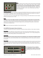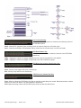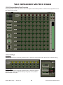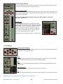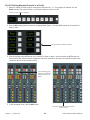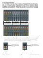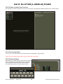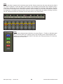
1
MPC4-D’s IKIS™ Automation
Installation Manual Version 1.04
December 06, 2005
2
IKIS User’s Manual Table of Contents
1.0
2.0
3.0
4.0
5.0
6.0
7.0
8.0
9.0
10.0
11.0
12.0
13.0
14.0
15.0
16.0
17.0
18.0
19.0
20.0
21.0
22.0
23.0
24.0
25.0
Getting Started (Starting IKIS)
Quick Reference Guide
Graphical User Interface (GUI) Overview
Project Page
Automation and the MPC4-D
Channel Overview Page
Shared Channel Page
Router Page
PEC/Direct Page
Console Options
Summing Matrix Page
Speaker Matrix Page
Music Monitor Page
Macros Page
Pan Modes Page
Meter Follows Page
Auxiliary Masters Page
Oscillator Page
Panel Processes Page
Profiling
Remote Faders Page
Labels (Slates) Page
Summing Faders Page
DSP Options
System Pages
Harrison by GLW Copyright Information 2004
No part of this publication may be copied, reproduced, transmitted, stored on a retrieval system, or translated into any language,
in any form or by any means without the prior written consent of an authorized officer of GLW Incorporated, 1024 Firestone
Parkway, Nashville, TN 37086.
Disclaimer
GLW Incorporated makes no representations or warranties whatsoever with respect to the content of this document and specifically disclaims any implied warranties of merchantability or fitness for any particular purpose. We reserve the right to make
alterations as technical progress may warrant at the discretion of GLW Incorporated. GLW Incorporated has no obligation to
notify any person or entity of any changes and/or revisions to this publication. We reserve the right to change materials and
specifications without notice.
Proprietary Information
The information contained in this document is the property of GLW Incorporated and is proprietary to and a trade secret of GLW
Incorporated. This document and the information contained herein and derived therefrom are not to be disclosed to any person
without the express written consent of an duly authorized officer of GLW Incorporated.
3
4
1.0 GETTING STARTED
1.0.00 Starting IKIS™
*Note: After starting up the computer, be sure to wait until the operating system is fully booted before
launching IKIS. IKIS is booted when the desktop is completely drawn.
1.0.01 Launching IKIS
Launch IKIS by booting the computer and double clicking on the IKIS console icon (Figure 1). Once the IKIS software has been loaded, the application will open to the page which has been configured as the opening IKIS
page. Clicking on any of the pages listed in the menu will cause that page
to appear on the screen. A single left click hold on any one of the menu
buttons will reveal a drop down menu. All screen navigation throughout the
IKIS console software can be accomplished via a left or right click on the
page menu (Figure 2), and holding and dragging the pointer to choose the
desired page.
Figure 2
Pages in the IKIS software are also mapped to function keys
on the keyboard. The F1 key will open the Filing page, the F2
key will open the Automation Page, etc. Not all pages are
accessible via the function keys so use the pull down menu to
access unmapped pages.
1.0.02 Starting a Multi-Computer IKIS system
1. Boot all machines and wait for them to load the OS.
2. Wait for the Remote Launch application to start on all
slave machines.
3. Start IKIS on the master machine. The master will then
launch IKIS on the slave machines.
Figure 1
*Note: If Remote Launch does not start when the computer boots, start
Remote Launch manually by double-clicking the Icon on the desktop.
The user should not run other programs while IKIS is active on the machine.
1.1.00 Selecting the Console Section
Figure 3
Using this navigation menu, the user can choose the console section
(Figure 3). Not only do the selections correspond to a specific console function
but it also corresponds to a specific data set associated with a console section. On large film consoles, console sections are typically confined to music,
dialog, effects and recordist functions, however other console configurations
are available.
*Note: that section menus are identical among console sections, however, certain functions available to each section may be different depending on how the console has been configured. Available channels, access
and permission is determined directly by the console configuration and
is specified by each customer.
Figure 4
1.2.00 Attention Lock
The icon in the upper left corner is the Attention Lock for IKIS (Figure 4). Selecting
the Attention Lock button will keep the IKIS software page from following actions on
the control surface.
Getting Started -- Section 1.0
5
IKIS Automation Platform Manual
1.3.00 Quitting a Multi-Computer IKIS system
Alt+Q will terminate the IKIS application after a short delay. This is the optimal method for closing the application.
1. Press Alt-Q on the master system while in the IKIS window.
2. Wait for all machines to shutdown.
3. If any of the slave machines do not exit IKIS, quit IKIS locally on that machine.
*Note: Never start a slave machine after the master has been running. The slave
will not work properly and may cause the system to be unstable. To add a slave
machine to the system you must quit IKIS as stated above and the follow the
restart procedure.
1.3.01 After quitting IKIS
At the desktop, click on the menu at the top of the screen. Select the desired action, i.e. Restart, Shutdown, etc. To
close IKIS without exiting the OS, click on the IKIS portion of the menu bar at the top of the screen. Choose Close
All. The computer will prompt you when it is OK to turn Off the machine.
Getting Started -- Section 1.0
6
IKIS Automation Platform Manual
2.0 QUICK REFERENCE GUIDE
The individual tables below provide a quick reference for common processes in the IKIS system. Main processes are
linked to portions of the IKIS where further information is available.
2.0.00 GUI Conventions
Page Menu Left click, select page. Left click hold, pages menu.
Level Controls Left click, coarse adjust. Right click, fine adjust.
Text Boxes Left click, keyboard entry. Right click, preset menu.
Router Source Button Left click, select point. Right click hold, shows list of current destinations and selection to
clear all routes for selected point.
2.0.01 Panel Conventions
Control Mode Selectors
Notch/Search Select
Return Mode
Reset
Clear a Channel’s RF Assigns
Clear a RF from All Channels
(ATTs, EQ, Aux, etc) Short hold toggles control mode for the given control. Long hold
toggles control mode for entire console section.
If notch or search EQ shape is selected, EQ band level control becomes a notch/search
toggle.
Hold solo and press mute button to toggle.
Double click Attention button to reset a given control to its default value. Faders go to
unity when double click reset is used. To reset the entire channel strip, hold the CLR
button located on the strip until the light goes out.
Hold channel attention for selected channel and double press mode button.
Hold channel attention for the desired RF and double press mode button.
2.0.02 Linking
New Link Press link button, press attentions of items to link, press link button to finish.
Add/Remove Link Press link button, press the attention in the link to be edited, press additional attention buttons to add links, press already selected attentions to remove links.
Link Fader vs. Channel Press channel attention to select a fader for linking. Press and hold channel attention to
select the entire channel for linking.
Clear All Links Double press the link button found on the channel strip or on the softkey matrix.
2.0.03 Pec/Direct
Set Selection Press set button, use enable to choose PEC/Direct set to display.
Key Linking Used to link keys within a set only. Press link button, press enable keys to link.
Set Linking Used to link sets together (ie. Key A1 fires key B1). Press set button, press link button, press
enable keys to link.
Unlink Temporarily removes the selected set from the linking system. Press and hold to clear key
links.
Quick Reference Guide -- Section 2.0
7
IKIS Automation Platform Manual
2.0.04 Profiling
Enter/Exit Profile Mode
Profile Keys (Layer Buttons)
Mapping Mode
Mapping Keys (Layer Buttons)
Copy Active to Profile
To enter, choose a profile (1-8) on the softkey matrix. To exit, deselect the active profile
on the softkey matrix.
Layer A - Next Profile
Layer B - Rotate Profile Right
Layer C - Rotate Profile Left
Layer D - Previous Profile
Hold a profile select button until it blinks. Hold the same button again to exit and return
to normal profile mode or press and release the button to exit mapping and profile
modes at the same time.
Layer A - Increment by 8
Layer B - Increment by 1
Layer C - Decrement by 1
Layer D - Decrement by 8
Choose copy active (page 5 on Softkey panel) then select profile.
2.0.05 Copy/Paste
Basic Operation Press copy, press attention(s) of item(s) to copy, press channel attention of target(s), press
paste.
Multiple copy/paste sources can be selected by pressing multiple attention buttons on selectSelecting Sources ed channel. Pressing an attention that has already been set as a copy source will perform a
paste.
Copy Fader vs. Channel Press channel attention to select a fader for copy. Press and hold channel attention to select
the entire channel for copy.
Targets can be selected individually. The entire console section can be selected by double
Target Selection clicking a channel attention. If copy/paste is setup to be global, a double click hold of a channel attention will select the entire console.
2.0.06 Sweet Spot
Basic Operation You must be in Profile Mode to create a Sweet Spot. Each Profile remembers if it has associated Sweet Spots.
A Sweet Spot requires a starting channel fader and ending channel fader. To select the startCreating a Sweet Spot ing point, double click and hold the Big Green ATT button for the desired starting point. While
holding the button marking the starting fader, press one of the remaining blinking Big Green
ATT buttons to select the ending fader. The fader's display's will go blank.
Placing Channels in a Pressing any ATT button will fill a Sweet Spot with those channels. Also mouse clicks on the
Sweet Spot graphic's overview page will place channels in the Sweet Spot.
A long hold on a Big Green ATT button (within a Sweet Spot) will toggle the lock for that Sweet
Locking a Sweet Spot Spot. Locking a Sweet Spot will momentarily display "Locked" in the fader's display. A locked
sweet spot will no longer chase channel ATTs. Unlocking a sweet spot will momentarily display "unlocked" in the fader's display. An unlocked Sweet Spot will again chase channel ATTs.
Scrolling within a Sweet Layer B scrolls down (for the S12) or up (for the MPC).
Spot Layer C scrolls up (for the S12) or down (for the MPC).
Double Click and Hold the Big Green Att button which was marking the starting point of the
Removing a Sweet Spot sweet spot, and the sweet spot will be removed from the profile. The text displays will go
blank indicating the sweet spot has been cleared, and no channels are associated with those
faders.
Quick Reference Guide -- Section 2.0
8
IKIS Automation Platform Manual
3.0 GRAPHICAL USER INTERFACE (GUI)
OVERVIEW
3.0.00 Getting to Know the GUI
Graphical interface with your system is available using a 2-button mouse along keyboard and an LCD interface.
This document assumes that the user familiar basic computer terms able to use device keyboard.
3.0.01 Page Navigation Menu
All screen navigation throughout the IKIS console software can be accomplished via either a left or right click on the
console section menu, and holding and dragging the pointer to the desired screen. Buttons will illuminate as the
pointer passes over them.
3.0.02 Page Selection
Figure 1
The initial four fields below the section select button (in Figure 1, the music
section is active) appear according to configurable default settings. The
menu is designed to display the page last selected from that particular
menu. For example, in the picture, the pointer ends up selecting the Filing
page from the submenu. That button will remain the Filing page access
button until or unless another page is accessed from that particular menu.
Because of this, the user can set up the fields to contain the four most
commonly accessed pages and easily navigate among them without having to re-navigate the drop menu. In Example A, the user has selected the
Filing Page, the Automation Page, the Router Page and the Pec/Direct
Page to occupy the quick select positions on the menu. These will remain until the user makes a different selection.
IKIS will revert to the default settings the next time the program is shut down and started again.
*Note: The majority of controls will have control surface equivalents.
3.1.00 GUI Conventions
The IKIS control environment is similar in nature to other, popular control environments, however an overview of the
conventions employed in the GUI may be useful.
Passing the pointer over the various screen elements will reveal whether an item has a function associated
with it. If the item is "live" a small dot will appear in the pointer and typically the object will highlight in some
way.
3.1.01 Controlling Console Functions
There are essentially three types of controls utilized on the IKIS GUI.
Round, Colored Buttons (Figure 2) - Clicking on these buttons turns a function either on or off. These buttons are
controlled by either a left OR a right click.
Gray, Pill shaped Buttons (Figure 3) - Clicking on one of these buttons typically causes IKIS to activate a function.
Colored Sliders (Figure 4) - These interactive elements function in place of faders and knobs and give a visual representation of an actual level.
Figure 2
Figure 4
Figure 3
GUI Overview -- Section 3.0
9
IKIS Automation Platform Manual
3.2.00 Global Controls - Function Activation (ON)
Some functions must be activated before they will take effect. Click on the small
green button in the upper right corner of the function window to turn On a function.
The On button is saved in libraries as well as part of macros.
3.2.01 Global Controls - Local Write Enable
Local Write Enable buttons are included with every function which can be written to automation. They are the Small
Red button in the upper right hand corner of the function windows. Functions can be enabled individually at the
Shared page. When any individual function is enabled, the Enable button in the Channel Select Panel of the Shared
Page will light up to indicate that a function on that page is enabled. Clicking on the Channel Local Write Enable
button will enable all functions on that channel. Local write enables may be written to macros. See the Automation
Page description (Section 6.0) for information about the master write enable.
3.3.00 The Default Color Scheme
Green bars control level (dB)
Blue bars control a time function
Yellow bars control ratio
To adjust slider controls, click anywhere inside the field and drag the slider up and down. It is not necessary to 'catch'
the leading edge of the slider; clicking anywhere in the field will work.
Coarse Adjust: Left click on the slider
Fine Adjust: Right click on the slider
The mouse wheel (where applicable) is an alternative method of adjusting the slider level. The up and down arrow
keys on the keyboard will also 'nudge' the levels.
There are other instances of alternate mouse techniques or "conventions". For example: the user can
vary the EQ Bandwidth in the Shared Page EQ section
graphics only via a right click and drag of the mouse.
GUI Overview -- Section 3.0
10
IKIS Automation Platform Manual
Value fields under the sliders can be adjusted using a text edit function. Clicking inside the field will reveal a pull
down menu (Figure 5) with default preset values. The user can either choose one of the presets or choose the
"Custom" selection. Choosing the "custom" selection will open a keypad (Figure 6) at which numerical entries may
be made.
Figure 6
Figure 7
Figure 5
Figure 8
An Indicator with a right-pointing arrow calls attention to the presence of a pull down menu (Figure 7).
On some functions such as the EQ, graph points (Figure 8) are deposited in the working field. Clicking on these
points enables the user to drag the points around the field and change settings.
At the Shared Page, the user can choose the channel source by clicking on the left side of the pill-shaped button
(Figure 9). Clicking on the field will display the Router source page and allow the user to choose and attach a
router point to that channel.
The user can click on the scroll bar and drag it up and down within a
field to scroll or use the up and down arrows arrayed at the top and the bottom of the scroll bar. On mouses with a wheel, the wheel moves the scroll
bar up and down in the field.
Figure 9
3.4.00 Global Controls - Libraries
The library facility in IKIS allows the user to set up snapshots or "Libraries" of console settings for instant recall.
A small gray button (labeled "Lib") next to a particular function indicates the availability of a user library.
Global/User Options, Speaker/Summing Matrix, Pan Modes, EQ, Gate and Compression Functions, as well as
entire channel settings can be stored and recalled individually using the libraries facility. A virtually unlimited number
of channels and section presets can be stored and recalled in this manner.
*Note:
Before saving a file to the Libraries facility, please refer to Section 4.0 (Ref. 4.1.10) of
this manual for instruction on setting up a Libraries “master” file for new projects.
GUI Overview -- Section 3.0
11
IKIS Automation Platform Manual
3.4.01 Using the Libraries
To Save a Setup in a Library:
1. Set the controls as desired.
2. Click on the LIB button in the upper right hand corner of the function window. Note that libraries store the set
up only for the function with which it is associated. The library will appear from the right of the screen and darken
the active window in the background.
3. Click in the New Lib Button. A virtual keyboard will pop-up. Use the mouse pointer to name the setup or use
the keyboard that accompanies the computer if available. The field will take up to 14 characters and spaces easily. Remember to click on or hit the Enter key. Clicking outside of the virtual keyboard without entering will cause
it to close without saving the set up name.
4. To delete a setup. Click on the X in the red circle next to the setup. Default setups cannot be deleted by the
user.
5. Click outside of the library to close the window and resume operation. Recalling a Setup Preset console settings can be recalled by clicking on the desired library icon to open the file and then clicking on the desired preset. The stored library setting will take effect immediately. Presets can then be compared against one another
immediately with audible and visual representations. Clicking on the slashed-out circle to the right of the name
will delete the file.
To Recall a Setup:
1. Click on the LIB button in the upper right hand corner of the function window. The library will appear from the
right of the screen and darken the active window in the background.
2. Click on the desired set up in the library. The setup will appear on the controls and be effective immediately.
Click outside of the library to close the window and resume operation.
*Note: You must SAVE the library entry before clicking out of the library window. Otherwise, the data will be
lost.
GUI Overview -- Section 3.0
12
IKIS Automation Platform Manual
4.0 IKIS PROJECT PAGE
4.0.00 Before Starting a Project
The Projects Page is an update to the previous version of IKIS. It was added to provide a simple alternative to the
existing filing structure present in the Filing Page. For those of you who are comfortable with the old filing structure,
take time to familiarize yourself with this addition for future use.
Each mixer has unique preferences and styles of mixing, so the IKIS filing structure was constructed to allow as
much flexibility as possible for the mix team. Because of the flexibility allowed by IKIS, Harrison has implemented a
default filing system that is accessed through the Project Page.
4.0.01 About IKIS Files
IKIS files are partitioned files. Each file is partitioned to accept function data from all users. This means that two
users working in separate console sections can save data to the same file without fear of overwriting each other's
data. This is good if all data is intended to be stored to the same file. Additionally this may be useful for storing all
similar data to one file or all of one user's data to one file. Careful planning will insure that data doesn't get misfiled.
Because it is not yet possible to "look into" a file before saving to it or deleting it, again, it is best if the users or project manager decide on a scheme ahead of time. The following information about the IKIS filing will help the users
decide on the appropriate filing method and instructs them in using the IKIS filing. More information can be found
regarding IKIS files in the Filing section of this manual.
*Note: There are two different types of files that can be stored and accessed in the IKIS Automation System:
Static Files and Dynamic Files. Static files are files that contain user configured "profile" information that
can be applied to different objects. Files stored in the Console, Macro and Library categories are all static
files. Dynamic Files are being constantly rewritten to the hard drive. Automation files are considered
dynamic and use a SMPTE time code reference for real-time automated mixing.
4.0.02 The Project Page is Divided into Five Distinct Sections
The Project Page consist of the following: Project Selector Panel, Console Panel, Automation/Mix Panel, Macro
Panel, and Libraries Panel.
Project Selector - Contains information about the open Project the
user has chosen
Console Panel - Control surface
settings files and Quick Keys. A
Quick Key is another form of control surface save and recall. The
files are created at the control surface as well as the software interface on the IKIS Automation
System.
Automation Panel - Files used to
create a complete mix
Macro Panel - Files that are
applied to a specific point on the
console. *Note: See the
Macro/Pan page for information
about creating and recalling
macros and quick keys.
Libraries Panel - Files that contain information that can be
applied across the entire console.
Project Page -- Section 4.0
13
IKIS Automation Platform Manual
4.1.00 Project Selector Panel
The Project Selector Panel consist of four buttons, one file identity field, two Timecode Fields and an Ignore button
Open/New Button
Clicking on the Open/New button will create a new Project that you name.
Duplicate Button
Clicking on the Duplicate button will perform a “Save As” operation.
File Display Field
Displays the name of the current Project used during the session.
Timecode State
Displays the status of the playback with the following call-outs: Stop, Play, Fast Forward, Fast Rewind, and Rewind
Timecode
Displays the current SMPTE timecode.
Ignore Button
Clicking on the Ignore button cause the timecode to be disregarded by the console.
4.1.01 Creating a New Project
1. In the Project Panel click on the Open/New button. In the sliding window to the right, click on the New Proj...
button
2. The keyboard will pop-up at which time you will enter a name for the new project and click Enter. The newly
created project name appears in the IKIS_Projects tree menu to the right of the screen.
3. After the new project is created, click anywhere on the screen to the left to return to the Project Page. The
name is now displayed in the file field of the Project Panel. *Note: See example above: “IKIS_Projects_Default”
4. There are also two options in the project selector that must be addressed; Synchronize and Recall. Highlight
the Synchronize projects across users button to open the same project for all users. Highlight the Recall the
console when a project is selected button to automatically set the console controls to the correct positions for
project start.
4.1.02 Opening a Project
1. In the Project Panel click on the Open/New button. In the sliding window to the right, click on one of the existing projects in the project menu. The project menu automatically closes and the chosen project is loaded along
with the console, macro, library and automation files that are unique to that project.
2. The projects path and name is displayed in the file field of the Project Panel.
4.1.03 Duplicating a Project
1. In the Project Panel click on the Duplicate button.
2. A window slides in from the right of the screen allowing the user to select the New Proj... button. The keyboard appears, name the Project accordingly and click Enter.
Now that the New Project has been established, the user can create the files for the remaining four panels.
Project Page -- Section 4.0
14
IKIS Automation Platform Manual
4.1.04 Console Panel
The Console Panel consist of the Recall button, Store button, Import button, New... button, and the file field.
Store Button
Clicking on the Store button will save the current console state to
the IKIS console file active on the console. The active file is highlighted by a green box.
Recall Button
Clicking on the Recall button will restore the console to the settings
currently stored in the console file.
Import Button
Clicking on the Import button will load a previous console file into
the file field for selection from the Favorites folder.
New... Button
Clicking on the New... button will create a new console file with the
naming convention of your choice.
4.1.05 Making a Console File
1. Use the controls to adjust the console settings (control surface or IKIS interface) to
a desired starting place.
2. At the IKIS Project Page make sure that the desired console section is active in
IKIS. (Figure 1 shows the “Right” section active in IKIS).
3. Choose New... in the Console Panel of the Project Page. The keyboard appears,
name the console file accordingly and click Enter. Unless the template file is
changed, every time this file is recalled, the saved settings will be recalled to the control surface. To save desired changes to the file while it is recalled to the control surface, click on the Store button.
Figure 1
4.1.06 Macros Panel
The Macros Panel consist of the Import button, New... button, and the file field.
Import Button
Clicking on the Import button will load a previous Macros file into
the file field for selection from the Favorites folder.
New... Button
Clicking on the New... button will create a new Macros file with the
naming convention of your choice.
File Field
Displays the files that are available for use during the session.
Project Page -- Section 4.0
15
IKIS Automation Platform Manual
4.1.07 Making a Macros File
Because the Macros file is constantly updating the information to the hard drive, create the Macros file before writing
any Macros to IKIS.
1. In the Macros Panel click on the New... button.
2. The keyboard will pop-up at which time you will enter a name for the new Macros file and click Enter. The
keyboard disappears and the newly created file is now displayed in the file field of the Macros Panel.
4.1.08 Automation Panel
The Automation Panel consist of the Import button, New... button, and the file field.
Import Button
Clicking on the Import button will load a previous automation file
into the file field for selection from the Favorites folder.
New File Button
Clicking on the New... button will create a new automation file with
the naming convention of your choice.
File Field
Displays the files that are available for use during the session.
4.1.09 Making a Automation File
Because the Automation file is constantly updating the information to the hard drive, create the Automation file before
mixing begins.
1. In the Automation Panel click on the New... button.
2. The keyboard will pop-up at which time you will enter a name for the new mix file and click Enter. The keyboard disappears and the newly created file is now displayed in the file field of the Automation Panel.
4.1.10 Libraries Panel
The Libraries Panel is a new feature to the IKIS Automation Platform. The Libraries Panel consists of the Import
button, New... button, and the file field.
Import Button
Clicking on the Import button will load a previous Libraries file into
the file field for selection from the Favorites folder.
New File Button
Clicking on the New... button will create a new Libraries file with the
naming convention of your choice.
4.1.11 Make a Library File
Because the Libraries file is constantly updating the information to the hard drive, create the Libraries file before writing any library items to IKIS.
1. In the Libraries Panel click on the New... button.
2. The keyboard will pop-up at which time you will enter a name for the new Libraries file and click Enter. The
keyboard disappears and the newly created file is now displayed in the file field of the Libraries Panel.
4.2.00 Automation, Macros, Libraries, and Quick Key Filing Functions
The Automation, Macros/Quick Keys and Libraries files are always writing information to a file, so it is advised to create working files for each of these. Libraries are more easily managed from within IKIS however it is more efficient to
establish a working file ahead of time.
Project Page -- Section 4.0
16
IKIS Automation Platform Manual
4.3.00 “Right Click” File Options
The pointer has several actions associated to the “right click” function. Depending on whether the file is in an active
state or inactive state, one of three actions can be carried out.
Export Button
Clicking on the Export button will send a copy of the selected file to the Favorites folder.
Duplicate (and rename) Button
Clicking on the Duplicate button will bring up the keyboard for renaming. After clicking the Enter button on the keyboard, the duplicate file (with new name) will be save to the same folder the original file resides.
Send to Trash Button
Files that are not active have the option of being sent to the trash. As a safeguard, active/highlighted files cannot be
deleted from the project.
Export Button
Clicking on the Export button will send a copy of the selected file to the Favorites folder.
Duplicate (and rename) Button
Clicking on the Duplicate button will bring up the keyboard for renaming. After clicking the Enter button on the keyboard, the duplicate file (with new name) will be save to the same folder the original file resides.
Project Page -- Section 4.0
17
IKIS Automation Platform Manual
5.0 AUTOMATION AND THE MPC4-D
The IKIS Total Automation can store all parameters and settings of all automatable control panels and make them
available for later recall and use. IKIS allows the user to use both static and dynamic automation to create a complete mix.
5.0.00 Storage and Recall of Automation Files
All automation data is stored on the computer as files. Files can be attributed to a particular function area for ease of
selection when recalling or saving a particular mix or portion of a mix. Additionally, console setups, libraries, macros
and quick keys can be saved in individual files on the main computer or on auxiliary storage medium for later recall
and use. More about these data storage options can be found in the Project Page Section (Section 4.0).
5.1.00 Play Speeds
A discussion of the IKIS automation must be preceded by an explanation of the different play speeds available for
writing to automation. These play speeds define the relationship between the timecode and the writing of the
mix pass. Unlike in the past, just because the timecode has stopped does not mean that changes to a mix pass are
not being logged.
There are three play speeds available in the IKIS automation. These speeds are determined in the Automation portion of the Console Options page. For a more detailed description of the available automation options refer to
Section 10.0 (Console Options Page).
Automation and the MPC4-D -- Section 5.0
19
IKIS Automation Platform Manual
Write at Play Speed
• Conditions: The Write Forward (any speed) option must be selected on the options page. The master write enable
button must be active. The local write enable buttons must be active for those functions on the console the mixer
wishes to record. (See Global Functions 3.2.01, Section 3.0).
• Actions: IKIS will continue writing to a pass while the time code is in any non-reverse mode (play, fast-forward,
stop). The automation will stop recording and then log a pass when the time code is put into any reverse mode
(rewind, fast rewind). In this mode, the mixer can advance to any place in the timecode, stop, make a change,
advance to another place in the time code (manually or using the advance controls on the timecode) stop and make
another change, etc. Changes will be recorded to time code as long as the time code is in any non-reverse mode.
Write Forward (any Speed)
• Conditions: The Write Forward (any speed) option must be selected on the options page. The master write enable
button must be active. The local write enable buttons must be active for those functions on the console the mixer
wishes to record. (See Global Functions 3.2.01, Section 3.0).
• Actions: IKIS will continue writing to a pass while the time code is in any non-reverse mode (play, fast-forward,
stop). The automation will stop recording and then log a pass when the time code is put into any reverse mode
(rewind, fast rewind). In this mode, the mixer can advance to any place in the timecode, stop, make a change,
advance to another place in the time code (manually or using the advance controls on the timecode) stop and make
another change, etc. Changes will be recorded to time code as long as the time code is in any non-reverse mode.
Always Write
• Conditions: The Always Write option must be selected on the options page. The master write enable button must be
active. The local write enable buttons must be active for those functions on the console the mixer wishes to record.
(See Global Functions 3.2.01, Section 3.0).
• Actions: In this mode, IKIS is always writing to a pass, even when the time code direction changes. A direction
change causes IKIS to end writing to the present pass and immediately begin writing to a new pass until the End button is pushed or the write enable is turned off.
5.2.00 Control Surface vs. IKIS Interface Control
Some automation functions are controlled from the Automation page of the IKIS interface, some only from the console, and some from either the Automation page or the console surface. This document discusses the Automation
Controls as controlled by the IKIS computer interface. For purposes of explanation, occasional reference is made to
the control surface, especially where a function is performed or viewed on the control surface. The primary purpose
of this document is to explain the IKIS Graphical User Interface.
5.3.00 MPC4-D Automation Status Description
The MPC4-D has 4 basic status situations with respect to the dynamic automation functions of the console system.
NO AUTOMATION
WRITE
READ
MODIFY
Automation and the MPC4-D -- Section 5.0
20
IKIS Automation Platform Manual
No Automation (Figure 1)
The console system can be used without ever using the dynamic automation functions. This mode of operating can
be useful at the beginning of a project where the console is used more in a “setup” mode getting the console to a
good starting point for a dynamic automation file to be started.
Write (Figure 2)
Every function on a channel strip can be dynamically automated. Red “Write Enable” buttons are provided for the
various sections of each strip Pan, EQ, Dynamics, etc. These Write Enables are used to indicate and activate when
a particular function is or will be writing to the automation.
Read (Figure 3)
After functions have been written to the automation they can then be played back on the console. When a function
has been written and is being played back, a Yellow Read LED (located just next to each Red Write Enable button)
will illuminate for that function indicating that the automation is in Read.
Modify (Figure 4)
The Modify status is the manipulation of the console system allowing previously written automation data to be re-written, updated relatively, added too, deleted from etc. It includes many modes and functions that allow a smooth transition between Writing and Reading automation data.
No Write data to the automation and no Read
data playing back
(Figure 1)
No Write data to the automation and no Read
data playing back
(Figure 2)
Reading back previously written data on a particular function
(Figure 3)
Over-writing to the automation new Write data
(Figure 4)
5.3.01 MPC4-D Automation Data Descriptions
THIS CONCEPT OF HAVING TWO SEPARATE DATA REGISTERS IS WHAT IS UNIQUE WITH RESPECT TO THE
MPC4-D CONSOLE AUTOMATION SYSTEM. These two unique data registers allow the operator to manipulate the
automation information by matching and writing new information along with punching in and preparing completely
new settings on any or all functions wile comparing them to previously written settings.
Automation and the MPC4-D -- Section 5.0
21
IKIS Automation Platform Manual
Panel Data
This is the information (settings) on the console surface that are active either when there is no Read data present, and/or
when a Red Write Enable button is active. Figures 1,2 and 4 above show when “Panel Data” is controlling the audio processing.
Read Data
Read Data is information (settings) that has been previously written to the automation and is being played back. Read
Data is indicated by the Yellow Read LED being ON. Figure 3 above shows the Read Data controlling the audio processing.
*Note: It is important to note that Panel Data and Read Data are two separate sets of Data and while in certain
situations they will be the same, in many other situations they will be different.
5.3.02 MPC4-D Automation Modes
There are many “Modes” that are provided on the MPC4-D system that allow the Modification of automation. The
MPC4-D has a host of automation “Modes” that are used to Write, Read, and Modify automation data.
MASTER WRITE
WRITE ENABLE(S)
READ
ABSOLUTE WRITE
UPDATE WRITE
WACT
ALL WACT
DEMAND
DOUBLE DEMAND
HOLD
INHIBIT
ABORT
MANUAL
DROP
RAMP
10
6
1 Master Write
No automation data will ever be written if MSTR WR button is not ON.
This button is located on the Automation Section of the Multi Matrix
panel in the center section. When this button is ON and only when this
button is ON is it possible to write automation information.
8
Write Enables
These are the local Red buttons on every channel strip for the various
functions. There are separate Red Write Enables for the Fader, Mute,
Panning, EQ, Aux Sends, Dynamics, Routing, Input, Insert Points, and
RF (Remote Fader assignments). These write enables must be ON for
any data to be written to the automation. These can be activated and
deactivated by using the ALL WR button in the center section which
turns on and off all write enables across all strips. There are separate
buttons to activate and deactivate all Faders (FWR button), Mutes
(MWR button) in the Automation Section of the Multi Matrix panel in
the center section. Individual write enables for an entire strip can be
activated and deactivated using the large ALL WR button near each
fader. Individual write enables can be activated and deactivated for
any individual function as well.
1
Automation and the MPC4-D -- Section 5.0
22
10
7
10
1
1
2
3
9
4
5
1
IKIS Automation Platform Manual
Read
Read is not a “mode” (there is not a button to select Read) but it is an automation “status” as described previously in
this chapter. Read data will be present when playing back an automation file where functions were written to the
automation. The Yellow Read LED/s will come on for those things that were written. When Read is present by itself
the function with the Read LED active can not be adjusted or changed without turning on the associated Read Write
Enable button which overrides the Read data with Panel data.
2 Absolute Write
Absolute Write applies to all functions on the console. AB or Absolute Write simply means that any data that is being
written for a particular function is NEW data and is NOT relative too any previously written data. The fader is the only
function on the console system that has the possibility to be in any other state than Absolute Write. If the fader is in
AB mode the AB LED will be ON in the fader area.
3 Update
Update (relative trim) is for faders only, and is the mode in which previously written fader moves can be updated relative to those moves. The Up (update) mode can be selected locally on any fader or globally using the Update button. In either case the mode will be indicated by the fader as the Up LED will turn ON.
4 WACT (Touch Write)
The WACT mode is a Touch Write mode for faders and the All WACT mode is
for faders and all other functions on the fader/strips. All other functions on the
strip (knobs and switches are “change write” functions where the initial change
of a function will drop that function into write.
WACT or “Write Active” when active allows a fader or function to be dropped
into write by touching (faders), or changing (all other functions) any fader or
function. After the fader or function is in write it will remain in write until all of
the WACT release criteria are met which are selectable in the “options page”.
Local WACT buttons are provided for activating WACT on any fader/strip and a global WACT button is provided on
the automation panel. A single press will activate WACT on faders only, and a double click will activate WACT on All
functions.
WACT can be used in conjunction with the AB (absolute) write mode or the Update (relative mode).
5 Demand (Touch Write)
The Demand mode is for faders only and allows the fader to be dropped into write by touching the fader. Upon
release of the fader the Write (panel) Data will drop back to the Read data.
When the fader is released in the Demand mode it will follow the ramp rate selected on the automation page.
Double Demand
A double click on the Demand function will affect the release where by the fader will NOT follow the ramp rate but
will instantly revert back to the Read Data.
Demand and Double Demand can be accessed locally at each fader or globally using the DMND button. A single
press activates Demand (with ramp release), and double click activates Double Demand (with instant revert to read).
6 Inhibit
The Inhibit mode is used to ignore any active Write Enables that are active on the console while playing back the
current Read for those functions.
This allows settings for a particular function or many functions to be prepared with new settings and are to be
punched in to the automation.
While Inhibit is not on, any function can be prepared by turning on the Red Write Enable and making the new settings active. When the Inhibit mode is activated the Red Write Enables will remain ON but the settings below will not
be active.
Automation and the MPC4-D -- Section 5.0
23
IKIS Automation Platform Manual
The current Read Data for the function/s will be active until the Inhibit node is released at which time the function/s
new settings will be punch in.
Inhibit can only be activated globally on the automation panel using the Inhibit button.
INHIBIT ON
Read is active, Write is ignored until INHIBIT is
released
(Figure 1)
INHIBIT OFF
(Figure 2)
7 Hold
The Hold mode allows any and all functions that are in write mode on the
console when timecode stops, to be written out to the end of the automation
mix. This allows the mixer to select Hold at any time before or during a pass
when it is decided that the data of the current functions that are in Write need
to be written out to the end. Hold is selected on the automation panel using
the Hold button.
8 Abort
The Abort function allows the data being written or that has just been written to a pass to be Aborted. Abort can be
selected while TC in rolling or it can be selected when the TC stops. The pass being written or which has just been
written will be deleted and the Read pass will revert to the prior pass.
9 Manual
The Manual mode is used to allow functions to be in Write locally but not actually written to the automation. This is
useful when there are some functions that need to be written during a pass and there are some functions that need
to be prepared but now written during a pass. The Manual button on the Automation panel will activate all Manual on
all channels. Manual can be activated on a channel by channel basis using the local MAN button near the fader.
When Manual is active, new write data can be prepared (Red Write Enables on) on channels with Manual active but
not written to the pass. Channels without Manual active and that have functions in Write will write during the pass.
By toggling Manual on and off, Write data can be punched into a pass.
Drop
Drop mode is used to “match” back to Read from Write. Drop can be used manually on faders be selecting DROP
while touching the fader and then moving the fader back through the previous Read value. When you pass through,
the Write will “drop” out. By pressing DROP without touching the fader the fader will Ramp back to Read if the Ramp
Rate is active, or it will instantly drop to Read if the Ramp Rate is not active. All level controlled functions can be
selected to Drop with the Ramp Rate by using the ALL DROP button on the automation panel.
Automation and the MPC4-D -- Section 5.0
24
IKIS Automation Platform Manual
Ramp
The Ramp mode lets the user define a specific slope between the panel data
and the read pass data. While in Demand mode, when the fader is released,
the fader will revert to the null point (Read data) according to the ramp time
and upon reaching the null point will disable the Fader Write. The Ramp is
determined by entering a time value in the Ramp value field. Clicking on the
field will bring up a keypad. Enter a value in milliseconds and hit Enter to
confirm the ramp time.
Get Read / Clear Read
Get Read is used to allow the Panel Data to be replaced with Read Data. Because these two data sets can be different, sometimes it is desirable to match the Read Data and the Panel Data. Pressing and holding the Get Read button will replace all Panel Data on the console with the Read Data that is present.
Clear Read is used to Clear the Read Data register. Pressing and holding the Clear Read button will clear the Read
registers on all functions on the console.
Merge
The Merge function causes update information recorded during a pass to be combined with the current read pass
information to create a new read pass. Fader moves are fully integrated into the new pass. The merge button will not
stay lit when the function has been activated. Update information is retained as separate data in the pass prior to
activation of the merge function but will expire according to the Auto Save Options if the pass is not made "safe".
(See Absolute and Update below)
End
Ends writing the automation pass regardless of the present write mode.
5.4.00 MPC4-D Automation Pass Architecture
The MPC4-D automation pass structure incorporates a simple Write, Read, and Read + Write method of operation.
Write Passes
Writing a Pass is accomplished by arming functions on the console using their Red Write Enables (any or all write
enables may be armed), activating the Master Write Enable, and rolling timecode. As TC is rolling everything that is
in Red will be writing including switches, knobs and faders functions.
Read Passes
After TC is stopped the previously written functions can be played back on the console. When the Red Write Enables
are turned off and TC is rolling the previously written functions will play back. The Read data is indicated on the console by Yellow LEDs next to each Write Enable. Note: if the Red Write Enables are left on they may be re-written on
the next pass.
Write + Read
After functions have been written, subsequent passes can be created by playing back the previously written functions
and then adding to them with new Write data, replacing them with new Write data, and/or updating them relative to
the Read data (faders only). Subsequent passes are created with Read plus and new Write data to make up the new
pass.
5.4.01 Automation Passes Section
The Automation passes section displays the previous red pass and the read pass. Each can be
managed allowing the user to select the current
pass.
Automation and the MPC4-D -- Section 5.0
25
IKIS Automation Platform Manual
5.4.02 The First Pass
During the First Pass of an Automation mix there are several key points that need to be understood.
1. Only the things that are armed will be writing.
2. Master Write Enable must be on or nothing will write.
3. When TC stops the last static data on the functions that are armed will be written to the end of time.
To Make a First Pass
1. The option “Automatic First
Pass in New Automation
File” must be set.
2. The option “Automatic First
Pass Written Using All
Auto” must also be set.
3. The first time that timecode
is in a play state, and the
Master Write Enable is on,
the console will create a
first pass.
The point at which TC stops is the point where “Virgin Territory”
begins. This means you have not rolled into this area yet. Even
thought you have not rolled into this area data will be written to the
end so that no matter where you roll to there will always be a base
of Read data present for the functions that were in Write Enable
during the pass.
THIS CONCEPT IS PIVOTAL TO UNDERSTANDING HOW SUBSEQUENT PASSES WILL BE HANDLED. SEE THE DIAGRAM
BELOW REPRESENTING THE FIRST PASS BEING WRITTEN
OVER TIME.
5.4.03 Pass Display
Displays the pass which is currently being used as the read pass.
Change the name of the pass to by clicking in the pass field. A virtual keyboard will pop-up. Use the pointer or the
computer keyboard to change the name of the pass. Enter to confirm the new name.
Time Stamp
Indicated the date and time that the pass was completed. This field is not editable. IKIS will use the internal clock
and calendar supplied wit the BeOS System.
Safe Mode
Pressing the Safe button while a pass is present in either the Swap or the read pass field insures that the pass will
not get deleted according to the schedule determined on the Options page. The Safe pass will be indicated in the
pass select window (represented in the example to the right).
5.4.04 Subsequent Passes
Subsequent Passes are created be combining Read data and any new Write data after a First Pass has been written. Virgin Territory may still exist during subsequent passes. The point at which TC stops will determine how the
new Write data will be handled after the stop point. Note in the diagrams below that if the stop point is in Virgin
Territory the functions in Write will write to the end. If the stop point is before Virgin Territory the writing will stop at
that point for those functions that are in Write. As the mixing process progresses eventually Virgin Territory will be
beyond the length of your particular mix and all Writing will stop based on the stop points. (See examples on next
page).
Automation and the MPC4-D -- Section 5.0
26
IKIS Automation Platform Manual
First Pass
Subsequent Pass
Subsequent Pass
5.5.00 Starting A New Automation File
*Note: This short section assumes that you have already read over the Automation Operational sections of
this manual and have a basic understanding of the “Project”, “Automation Pass Architecture”, and
“Automation Modes” sections of this manual.
Automation and the MPC4-D -- Section 5.0
27
IKIS Automation Platform Manual
Step 1 - Setup the console with a good starting point for the new automation file. You can use a Console recall file to
do this if you have one available or you can set the console up manually.
Step 2 - Open a new Automation File on the Project page.
Step 3 - Decide what functions on the console you want to include in the first pass of the automation file. Many
Harrison users select all functions to be included in the first pass. For this approach go to the center section and
select the All Auto switch to turn all red lights on. Or, you can individually arm any combination of red lights on the
console, for example faders only or several channels only.
Step 4 - Make sure the Master Write Enable switch is active in the center section. Remember, nothing will be written to the automation if this switch is not active.
Step 5 - Roll timecode and begin mixing. Everything you do on the functions that are armed will be recorded to the
automation. If functions are not armed you can still control them but they will not be included in the automation file.
You can add them to the automation file at any time on subsequent passes if you wish.
Step 6 - Stop the TC from rolling at any point. When TC is stopped the last settings on the functions that are in red
will write out to the end of time.
Step 7 - Turn off the red lights by pressing the All Auto switch in the center section. This will turn off all red lights.
Step 8 - Roll TC again and watch your mix play back. You can add to or modify any or all of the functions on the
console at any time during subsequent passes.
Step 9 - Use all of the special “Automation Modes” to manipulate the Write and Read data on the console to create
as many subsequent passes as you like in the new mix.
5.6.00 Timecode Controls
Ignore
The Ignore button tells the console to disregard the timecode. Caution: This is a global state.
Timecode State
The timecode state window displays the state of the timecode (i.e. play, stopped, rewind, FF, etc.).
Timecode Window
The timecode window displays the incoming SMPTE timecode in hours, minutes, seconds and frames.
Mix Start Time
The mix Start time allows the user(s) to designate the
start time of a mix pass. This value is changed by
clicking in the mix Start Time window and entering a
new value using the pop-up keyboard. This functions
as a safety feature that prevents the user from writing
anything to the mix until the start time has been
reached.
Automation and the MPC4-D -- Section 5.0
28
IKIS Automation Platform Manual
Mix Offset
The mix Offset inserts or deletes blocks of time from the timecode to alter the start time for the mix. For example, in
the Mix Offset Chart (below) the mix has been set to start at 1:00:00:00. In the chart, three seconds have been
added to the beginning of the mix by offsetting the mix start time. This value can be changed by clicking in the mix
offset window and entering a new value using the keyboard. (See chart on next page)
Display Format
Use the pull down menu to select the appropriate frames per second format. This format may be different from the
input format. This format will be used by the mix start, the mix offset, the edit start and edit length fields.
Input Format
Use the pull down menu to select the appropriate timecode input format. Caution: This setting must match the
actual format of the incoming timecode for the system to work properly.
5.7.00 Mix Editor Controls
IKIS offers a mix editing system that allows the user to delete or insert time from a real-time automated mix at a
specified location. The mix editor will use the data from the read pass and create a new pass with the edit applied.
The mix editor can be controlled only from the IKIS Automation page.
Using the Mix Editor
1. Select the start time of the edit by clicking the Edit Start Window in the mix edit section. A keyboard will pop up
for the user to enter the starting timecode point. Type the timecode value and select the Enter button.
2. Select the duration of the edit by clicking in the edit length window in the mix edit section. A keyboard will pop
up for the user to enter the length of the edit. Type the amount of time to be inserted into or deleted from the mix
and select the enter button.
3. To Delete time from the mix, click on the Del button. If there is less time available than the edit duration, the
timecode will go to zero.
4. To Insert time into the mix, click on the Ins button. The time will be inserted after the Edit Start time.
5. Run timecode to view the changes.
Automation and the MPC4-D -- Section 5.0
29
IKIS Automation Platform Manual
Auto Extend Controls
The Auto Extend function automatically reactivates all functions active in WACT at the last point the timecode was
stopped. For example, with Auto Extend inserted, Local Write Enables active at the end of the Pass-1 (1:07:00) will
automatically re-insert at 1:07:00 during Pass 2.
The yellow button to the upper right of the large
enable button (WRes) is the WACT Restricted button. This button Isolates all Local Write Enables
physically inserted from the Auto Extend function.
Parameters using the wact (Write Active) are the
only functions controlled by the Auto Extend.
Automation and the MPC4-D -- Section 5.0
30
IKIS Automation Platform Manual
6.0 CHANNEL OVERVIEW
The Overview Page is a summary of the Console Input Channels. This screen appears when the user clicks on the
Select Button (Figure 1) on the Channel Select Panel of the Shared Channel Page. It can be used to monitor the
status of all the channels at once as well as quickly access a particular channel. Clicking on a channel square on the
Overview Page will take the user to the Shared Page with the selected channel active.
The Overview Page shows the Channel Number, the Solo and Mute Status, and the Level.
There is also a small input meter included in the box.
Figure 1
Channel Overview Page -- Section 6.0
31
IKIS Automation Platform Manual
32
7.0 SHARED CHANNEL PAGE
7.0.00 Shared Channel Panel Descriptions
The Shared Page in IKIS is similar in function to prior Harrison consoles with several major enhancements. Not only
does the new graphics design of IKIS give a stunning new look to this section, but signal processing control and
access to the console functions has been dramatically improved through the arrangement of this interface.
A variety of functions can be controlled from the Shared Page.
Figure 1
The Channel Select Panel
By clicking the Processing/Assign
button (Figure 1) the user gains
access to alternate Shared Page
functions (Figure 2).
Figure 2
The Bus Assign Functions
Allows the user access to the Mic
Pre Assigns,the Stereo Linking
utility, the Assign Busses, the
Reassign Busses and the Aux
Sends.
The Processing Functions
Gives the user access to the
Adjustable Signal Flow Controls
Panel, the EQ Panel, Gate
Controls Panel, Dynamics
Display Panel and Compressor
Controls Panel.
Various Persistent Functions
Also on the Shared Page are
those persistent functions which
are not affected by pressing the
Processing/Assign button.
Shared Panel Page -- Section 7.0
33
IKIS Automation Platform Manual
7.0.01 Constant Shared Page Functions
Channel Select Panel
Select the Lib (Library) button to access the Channel Library. The default state is everything off
and unassigned. The Unity setting sets the fader at unity with the channel muted.
Use the forward and reverse arrows to move through the channel bank. Active functions are cleared
upon leaving a channel. Use the channel library to save channel settings.
Input Section
Click on the desired input to the channel. The default input is the A input.
The selected input for the channel will save as part of the channel library settings.
A - Selects the "A" input as the channel source.
A+B - Sums the inputs to the channel. The A and the B input share the channel
controls.
B - Selects the B input as the channel source.
Phase Invert Button
Inverts the phase of the channel. If the A+B is selected the Invert command will invert the phase
of the summed signal.
Channel Source
Selects the source for the channel. The selection defaults to the null
point on the router. The screen will jump to the Router Track Select
page. At the Router page, click the desired signal source for the
channel.
Delay and Trim
Use the individual pull down menus to adjust the Delay (samples and
milliseconds) and the Trim.
To change the user name for the input to the channel, use the enter
function on the Slates Page or to change individual click on the black
portion of the Channel Source button. Clicking on it
will open a virtual keyboard. Use the pointer or the
computer keyboard to change the name of the
Source.
Fader
Fader moves can be written to the automation. Click on the red button in the upper right corner of
the box to put the individual fader into write enable mode. The larger green slider represents the
fader with fader levels indicated to the left of the slider. The level is adjusted by clicking and holding
anywhere in the slider field and moving the mouse or trackball. Left click is Coarse adjust; right click
is Fine Adjust. Additionally, you may click in the field below the slider to access a menu of common
presets. Selecting "custom" will cause an electronic keypad to appear. Use the pointer or the computer keyboard to enter the numbers. Confirm the value using the Enter button on either the keypad
or on the keyboard.
Shared Panel Page -- Section 7.0
34
IKIS Automation Platform Manual
• Input Metering
The input meter to the right of the slider measures the channel input level.
• Solo
Click on the Yellow "S" button to solo the channel. The fader will respond depending on the
fader settings as established by the console options.
• Mute
Click on the Red "M" button to mute the channel. The mute will respond depending on the
mute button settings as established by the Console options. The mute may be written to the
automation.
Remote Fader
Click on the RF button to access the Remote Fader Bank. The number and labeling of the Remote Faders in the
bank will depend on the console configuration. The example illustrates a three section console Music, Dialog and
Effects with 32 remote faders per section. Click on the Remote Fader(s) to which the channel is to be assigned.
Each Channel can be assigned to a maximum of four Remote faders.
• Fader Return
The blue "R" Return button isolates the channel by
blocking the selected channel from muting when
the Wet listed (destructive solo) function is selected on another channel.
• Audio Mute
The little red Audio Mute button is a non-automated mute that mutes
all audio on a channel regardless of the state of the automation.
Pan Controls
Adjust the spread, divergence and LFE
(Low Frequency Extension) using the colored sliders. Also, right clicking on the text
fields will activate a menu of common preset values. Clicking on the custom selection in the menu brings up a keypad. Enter the value using the pointer or the keyboard number pad.
Pan the signal by clicking on the square handle in the pan field. The intensity of the
light as it ranges around the field represents the audio signal panning intensity and
direction. The pan directions on the GUI represent a typical 7.1 pan mode (Left, LeftCenter, Center, Right-Center, Right, Left Surround, Right Surround) however custom
pan modes may be established at the Macro/Pan page.
The pan control may be automated; it is the virtual equivalent of the joystick control
developed by Harrison for use in panning audio signal on film consoles. The Pan
control has no library function associated with it.
Shared Panel Page -- Section 7.0
35
IKIS Automation Platform Manual
7.0.02 Assign View Functions
The Assign view is named so because the most prominent component in the window is the Bus Assign Matrix. This
window shows the 96 main busses (96 busses are included in the "Mega Bus" console, 48 main busses in the normal Bus console). Buttons in the Reassign window show the 32 reassign busses (32 Reassign busses are included
in the "Mega Bus" console, 16 in the normal bus console).
Mic Preamplifiers
The Shared page possess an interface to the Mic Preamplifiers. Use
the arrow buttons to reveal pulldown menus to choose the Channel
Source from among the available Mic Pre Sources. The user can
also choose the Mic Pre as the channel source from the Router
Page.
• Mic Input Select
Click on A, B or C to select the input to the Mic Pre. The active
Input will light up.
• Pad
Click on the Pad button to apply the 20 dB pad to the signal.
The button on the IKIS interface will light up when the Pad is
active on the Mic Pre Input.
• 48V (Phantom Power)
Phantom power applies +48 volts DC on the input of the Mic
Pre with reference to the shield. Phantom Power will not work
when the shield is lifted. Click on the 48V button to activate
phantom power on the Mic Pre Amplifier. The button will light
up when the Phantom Power is active on the Mic Pre Input.
• Lift (shield)
The Lift function lifts pin-1 on the XLR connector for the selected microphone Input. This may be useful when
isolating ground loops. Click on the Lift button to lift the ground on the Mic Pre. The Lift button will light up when
the shield is lifted.
• Mic Pre Gain
Use the slider to adjust the Mic Pre Gain. The Gain for the Mic Pre is adjustable from 25.5
dB to 75.0 dB. To
select a preset value, click on the Input level display. A menu of preset values will drop
down. Choose one of the
preset values or choose "custom". Clicking on custom will cause a number keypad to popup. Use the pointer or
the keyboard keypad to type in the value and hit enter to confirm the value.
• Stereo Linking
The stereo linking function allows the user to connect natural pairs (i.e. odd-even) of channels into a stereo pair.
When the channels are linked, the odd channel is the left feed and the even channel is the
right feed. When the channels linked in a stereo configuration are stereo pan mode, the
pan control becomes the balance control.
• Enable
Click on the enable button to activate the function. If the active channel is an odd numbered channel, it will pair
with the next consecutive even channel. The odd channel becomes the left feed and the even channel becomes
the right feed.
• Crossfeed
Click on one of the crossfeed buttons to re-assign the channel inputs.
•L>R
This function causes the input to the left channel of the stereo pair to feed to the right speaker.
Shared Panel Page -- Section 7.0
36
IKIS Automation Platform Manual
•R<L
This function causes the input to the right channel of the stereo pair to feed to the left speaker.
• Width
The width function determines the concentration of the signal being fed to the speaker. Use the Switch button to
toggle between the left and right components of the stereo pair. The width applies to the active input (i.e. Input A,
or B).
Assign Busses
Choose the Pan mode from the pull down menu. More about setting up the Pan modes is discussed in the Pan
Section of this page.
Click on the buttons to assign the selected bus to a pan placement.
Click on a selection to deselect or click on the CLR button to clear the entire matrix.
Reassign Busses
Choose the Pan mode from the pull down menu. More about setting up the Pan modes will be discussed later. The
Assign busses and the Reassign busses may use different Pan modes.
Click on the buttons to assign the selected bus to a pan placement.
Click on a selection to deselect or click on the CLR button to clear the entire matrix.
Aux Sends
Use the Aux Sends overview screen to turn On the Send and adjust the level. Clicking on the text field under the slider will open a drop down menu with some common preset values available. Note that in the bank of Aux Send controls, individual Aux Sends are color coded according to which user they are assigned to. Note that in the section
menu, user selections are different colors (red, green or yellow).
Shared Panel Page -- Section 7.0
37
IKIS Automation Platform Manual
7.0.03 Processing View Functions
Signal Flow
The signal flow section of the shared page is where the user can adjust the signal flow for an individual channel as
desired using the GUI interface to the console. Click on elements and drag to like-shaped locations. The signal flow
is read left to right. Note that the compressor and gate may occupy the same large rectangle if desired. The signal
flow is automatable. The section has a library feature where signal flow setups can be saved and recalled.
There is no direct out indicated on the signal flow, however, this can be easily accomplished using the patch inserts.
For instance, the Pat2 is nominally placed at the end of the signal flow. The Pat2 feed would then be ideal to use as
the Direct out.
Please note the following important facts:
*Pat2 uses the B input for its patch return. You may not have the B input selected and the Pat2 inserted at the same
time.
*The Pat1 and Pat2 feeds are always active regardless of the state of the Patch 'in' switch.
*The last eight channels of every channel card do not have a Pat2 feed. This is reflected on the IKIS screen. For
these channels you may use the Pat1 feed as a direct out.
*The router config is flexible and may have
the Patch names customized to your desires.
The default config may name the Pat2 feed
as 'Direct out'.
Pat1 = Patch 1
Flt = Filter
Cmp = Compressor
Gte = Gate
F = Fader
Pat2 = Patch 2
EQ and Hi-pass /Low-pass Filter Section
Note that this is the first field on the Shared page with three buttons in the upper right corner; the green On button,
the yellow read data button and the red write enable button. Note that the Hi and Low pass filters are also controlled
in the same manner as the EQ however they must be turned on separately from the EQ.
The EQ section and the
filter section both possess libraries. The EQ
library has hard coded
settings to return the EQ
to the flat state for either
mode. Click on the numbered band buttons to
make the control
squares appear in the
field. Click on the
square and drag it
around the field to
adjust the EQ for that
band. The EQ will display a graphical representation of the setting.
Note that the control
parameters appear next
to the square as you are
making adjustments. To control the bandwidth (Q), right click on the mouse or trackball and scroll up and down to
make adjustments to the bandwidth.
Shared Panel Page -- Section 7.0
38
IKIS Automation Platform Manual
The Hi and Low pass filter operate in the same manner however they move only along the horizontal axis.
The EQ section operates in two modes: 4-band parametric EQ or 8-band graphic EQ. Switch between modes using
the mode toggle button in the upper left of the EQ field.
*NOTE: If you switch modes in the EQ section without saving your EQ set up in the EQ library, your EQ settings will
be lost. Filter settings must be saved in a separate library as their settings are not saved with the EQ data. Filter data
remains unaffected when switching between modes as the 8-band EQ does not use the filters.
Each band can be set individually or choose the desired shape or type of EQ using the EQ Shape menu below each
band insert button.
Available Graphic EQ
shapes are:
Bell, graphic bell, notch,
search, Lo shelf, Lo
pass 6 dB, Lo pass 12
dB, Hi shelf, Hi pass 6
dB, Hi pass 12 dB, Pan
Section. The Pan section must be activated
using the green activate
button in the upper right
of the field.
Dynamics
The entire bottom row of controls represent the Dynamics controls. To the left of the dynamics display are the Gate
controls and to the right are the Compressor controls. These functions may be moved around in the signal flow using
the Signal Flow control section at the top right of the Shared page.
Like the EQ and the Pan controls, the Gate and Compressor controls must be turned on to be active in the signal
flow. Use the buttons in the upper right hand corner to put the control into the signal flow.
Faint lines in the field are markers for the values indicated to the left of the slider.
Dynamics controls are graphically represented in the Dynamics Display window. Activating Gate controls affects the
left side of the Dynamics Graphic display. The Compressor controls affect the right side of the Dynamics Graphic display.
Shared Panel Page -- Section 7.0
39
IKIS Automation Platform Manual
Gate controls
Threshold(dB)
Use the slider control to adjust the Threshold. The range is from: -60 to 0 dB.
Clicking on the text field below the slider will pull down a menu with preset value selections. Select the custom selection to display a keypad. Use the pointer to enter a value or the keyboard number keys. Be sure to Enter before clicking outside of the box or the value will not be acknowledged.
Ratio
Use the slide control to adjust the
Ratio. The range is from: 100:1 to
1:1. Clicking on the text field below
the slider will pull down a menu with
preset value selections. Select the
custom selection selection to display
a keypad. Use the pointer to enter a
value or the keyboard number keys.
Be sure to Enter before clicking outside of the box or the value will not
be acknowledged.
Depth (dB)
Use the slide control to adjust the Depth. The range is from: 0 to 117 dB. Anything below 117 dB is recognized as
"off". Clicking on the text field below the slider will pull down a menu with preset selections. Select the custom selection to display an electronic keypad. Use the pointer to enter a value or the keyboard number keys. Be sure to Enter
before clicking outside of the box or the value will not be acknowledged.
Attack (ms)
Use the slide control to adjust the Attack time. The range is from: .5 to 200 ms. Clicking on the text field below the
slider will pull down a menu with preset value selections. Select the custom selection to display an electronic keypad.
Use the pointer to enter a value or the keyboard number keys. Be sure to Enter before clicking outside of the box or
the value will not be acknowledged.
Hold (ms)
Use the slide control to adjust the Hold time. The range is from: 0 to 2000 ms (2 seconds). Clicking on the text field
below the slider will pull down a menu with preset value selections. Select the custom selection to display an electronic keypad. Use the pointer to enter a value or the keyboard number keys. Be sure to Enter before clicking outside
of the box or the value will not be acknowledged.
Release (sec)
Use the slide control to adjust the Release time. The range is from: .003 seconds (3 milliseconds) to 10 seconds.
Clicking on the text field below the slider will pull down a menu with preset value selections. Select the custom selection to display an electronic keypad. Use the pointer to enter a value or the keyboard number keys. Be sure to Enter
before clicking outside of the box or the value will not be acknowledged.
Compressor Controls
Threshold(dB)
Use the slider control to adjust the
Threshold. The range is from: -60 to
0 dB.
Clicking on the text field below the
slider will pull down a menu with preset value selections. Select the custom selection to display a keypad.
Use the pointer to enter a value or
the keyboard number keys. Be sure
to Enter before clicking outside of
the box or the value will not be
acknowledged.
Shared Panel Page -- Section 7.0
40
IKIS Automation Platform Manual
Ratio
Use the slide control to adjust the Ratio. The range is from: 100:1 to 1:1. Clicking on the text field below the slider will
pull down a menu with preset value selections. Select the custom selection selection to display a keypad. Use the
pointer to enter a value or the keyboard number keys. Be sure to Enter before clicking outside of the box or the value
will not be acknowledged.
Gain (dB)
Use the slide control to adjust the Gain. The range is from: off (below 117 dB) to +10 dB. Clicking on the text field
below the slider will pull down a menu with preset value selections. Select the custom selection selection to display a
keypad. Use the pointer to enter a value or the keyboard number keys. Be sure to Enter before clicking outside of the
box or the value will not be acknowledged.
Attack (ms)
Use the slide control to adjust the Attack time. The range is from: .5 to 200 ms. Clicking on the text field below the
slider will pull down a menu with preset value selections. Select the custom selection to display an electronic keypad.
Use the pointer to enter a value or the keyboard number keys. Be sure to Enter before clicking outside of the box or
the value will not be acknowledged.
Sidechain EQ
The side chain EQ possesses its own On button. Click on the green button below the sidechain EQ to insert it into
the signal path. Click on the square to adjust the side chain EQ curve. This control emulates the 8 band graphic EQ
control. Choose the shape of the sidechain EQ using the pull down menu below the window. Click on the square to
adjust the curve. As you are adjusting the curve, values are display next to the control square. Some shapes are
subject to bandwidth control. Right click and use the mouse or trackball to adjust the Q.
Release (sec)
Use the slide control to adjust the Release time. The range is from: .003 seconds (3 milliseconds) to 10 seconds.
Clicking on the text field below the slider will pull down a menu with preset value selections. Select the custom selection to display an electronic keypad. Use the pointer to enter a value or the keyboard number keys. Be sure to Enter
before clicking outside of the box or the value will not be acknowledged.
Shared Panel Page -- Section 7.0
41
IKIS Automation Platform Manual
Router Page -- Section 8.0
42
IKIS Automation Platform Manual
8.0 ROUTER PAGE
8.0.00 Router Page Overview
The IKIS router serves as a recallable patch bay, allowing the user to save all router setups and connections within
the Channel information in the Channel setup library.
The IKIS Router allows the mixer to choose among multiple paths into and out of the console to send the selected
signal or group of signals along the desired path to the final destination. Any source signal may be routed to any destination on the console. The path of the audio signal can intersect the router multiple times. For example, the input to
an audio channel can be selected via the router destination; the assignment from the channel can interface to a
router source; a destination of the router can interface to a tape machine, the output of the tape machine can interface to a source of the router/switcher, the destination of the router can interface to the monitor system. All connections can be saved and recalled. The router is custom configured according to the system so the number of system
inputs and outputs will vary as to the router configuration.
The router is configured according to the size of the console.
Full bus consoles will have:
- 96 "stem" busses, sectional or console wide
- 32 auxiliary sends, sectional or console wide
- 32 mix (reassign) busses
- 16 monitor busses
- 4 "listen" busses
Router Page -- Section 8.0
43
IKIS Automation Platform Manual
Half bus consoles will have:
- 48 "stem" busses, sectional or console wide
- 16 auxiliary sends, sectional or console wide
- 16 mix (reassign) busses
- 16 monitor busses
- 4 "listen" busses
In this discussion, an Input refers to the input to the router and output refers to the output from the router. For example,
the PEC/Direct signals appearing in the source pages represent signals coming out of the console but they can be used
as another input to the router if desired.
With few exceptions, any source can be routed to any destination. Exceptions occur when track assignment is made at
the PEC/Direct page and some destinations are barred from assignment (Figure 1). Any signal appearing on one of the
router source pages can typically be routed to any destination on the router destination page. A single source may be
routed to a single destination (Figure 2, Track 1 is routed to Channel 1) or multiple destinations (Figure 3, Track 1is
routed to Channels 1 through 8). A source range may also be routed to a destination range (Figure 4, Tracks 1 through
8 are routed to Channels 1 through 8 consecutively). By default, all channels are assigned to the null position.
To unassign the input to any destination, route the signal to null. To unassign any source assignment, at the source
page, right click on the source signal. A drop down menu (Figure 5) will appear showing all the destinations to which the
source is assigned. In the example, Track 8 is assigned to both Channel 1B and Channel 9. Clicking on one of the menu
selections will clear the connection. Clicking on the Clear all will unassign that source from all destinations.
Figure 2
Figure 1
Figure 3
Figure 4
Figure 5
Router Page -- Section 8.0
44
IKIS Automation Platform Manual
8.0.01 Source Pages
Source pages represent inputs to the Router.
Each source page displays up to 224 input sources in a grid which may be as large as 14 x 16. Each square represents one input or signal source.
MADI Source
MADI Sources are the MADI signals coming into the router from the I/O Cards. The number of MADI sources
depends on the number of Input sources to the router and the number of MADI Input Cards in the router.
Sends A page
The Sends A source pages are the A Insert Sends.
Sends B page
The Sends B pages are the B Insert Sends.
PEC/Direct Source Page
The output from the PEC/Direct can be sent to any destination.
8.0.02 Destination Pages
Destination pages represent outputs from the Router. Each destination page displays up to 224 router points in a grid
which may be as large as 14 x 16.
MADI Destinations
MADI Destination pages send output directly to the MADI out spigots on the router where signal is routed to the AES
or analog output carrier in the system I/O.
Chan In A
Chan In A destinations represent the A input to the channel.
Returns
Returns on the router are the Insert returns to the console.
Chan In B
Chan In B destinations represent the B input to the channel.
PEC/Direct Destination Page
Routing to the PEC/Direct Input can be done both at the router and at the PEC/Direct Page (Refer to Section 9.0 for
more detailed description of PEC/Direct Page).
Summing Matrix
Connection to the summing matrix can be made at either the summing matrix page (Refer to Section 11.0) or at the
router.
Meter Page
Use this page to assign the router output to a meter. Assignment can also be made at the Meter follows page (Refer
to Section 16.0 for more detailed description of Meter Follows Page).
Router Page -- Section 8.0
45
IKIS Automation Platform Manual
46
9.0 PEC/DIRECT PAGE
9.0.00 PEC/Direct Page Overview
The PEC/Direct Control works in conjunction with the Router to control and monitor external recording machines.
The PEC/Direct page works in conjunction with the PEC/Direct panel on the control surface. Simply put: PEC mode
monitors the output from an external recording machine. Direct is the output from the console bus. The PEC/Direct
page allows the operator to quickly define the tracks which get routed to the summing matrix for pre/post monitoring
and track enabling.
The 56 PEC/Direct busses are arrayed in seven groups of eight busses and assigned designations A-G. These
seven groups are also controllable from the control surface.
Select the Source Signals, Busses and Output< The Track
select buttons define the PEC input to the PEC/Direct switching (Figure 1). The PEC/Direct page defaults to the 96 Main
Busses (96 for Full bus, 48 for half bus consoles). Click on
the Track field to select the Track.
Select an individual track or click on the group button to select
the Group of eight in the row. To Unassign the tracks, click on
the null group at the top of the field.
Figure 1
PEC/Direct Page -- Section 9.0
47
IKIS Automation Platform Manual
9.1.00
Select the Bus (Direct)
This button defines the Direct
input to the PEC/Direct switching. The Bus select defaults to
the main and reassign busses.
Click on a field to select the
bus. Select an individual Bus or
click on the group button to
select the group of busses. To
Unassign the busses, click on
the null group at the top of the
page. (Example to left)
9.2.00 Select the Output
The Output defaults to the
Nx16 summing matrix. This
connects the output of the
PEC/Direct to the input of the
summing matrix. Click on the
Output field to select the individual output or click on the
group to select the group. To
Unassign the output, click on
the null group at the top of the
page. (Example to right)
*Note: Once assignments are made at the PEC/Direct Page, they are disallowed from further assignment.
Other assignments for the PEC/Direct can be made from the Router, i.e. metering the output from the PEC/Direct,
metering the Input to the bus, etc.
*Note: When assignments are made using the PEC/Direct controls, these assignments can be viewed on the Router
Pages. As a security measure, the assigned Tracks, Busses and Outputs are barred from any changes made at the
Router.
PEC/Direct Page -- Section 9.0
48
IKIS Automation Platform Manual
Bias Enable Button
Click on the green "E" key to enable the track to record. The Bias key will light up when the record machine turns on.
Mute Button
Click on the red "M" to mute the bus. This disables the output to the monitor facilities.
Solo Button
Click on the yellow "S" to solo the bus. The Solo function mutes all outputs to the monitor except the soloed track.
Using this function does not affect signals going to and from external recording devices.
Bias Key Button
Click on the Bias button to control the record enables on an external recording device. When the external device is in
record mode, the BIAS button will illuminate. The PEC/Direct track must be enabled before the Bias key will activate
the Recording device.
PEC Button
Use the PEC button to toggle back and forth between PEC and Direct monitor modes.
Bias Triggers
There are seven sets of Bias triggers on the PEC/Direct Page. IKIS allows the
user to choose two automation users (i.e. Music, Dialog Effects) to tie to the
bias status. For example, if PEC/Direct set A is set up to trigger the music
automation panel, when the first bias tally is activated, the master write enable
in the Music Section Automation will activate. When the last Bias tally in set A is
turned off, the master write enable will turn off.
PEC/Direct Page -- Section 9.0
49
IKIS Automation Platform Manual
50
10.0 CONSOLE OPTIONS PAGE
10.0.00 Console Options Page Overview
Console Options allow the user to choose the functionality of the console section or in some cases the entire console. Most options apply to the SeriesTwelve, the ST2, and the MPC however because of hardware differences,
some options are exclusive to a console model.
10.1.00 Global Options
These options affect the functionality of the entire console. Note Any user can change these options; there is no lockout feature.
Panel Awake/ Asleep
This option, useful for screenings or anytime you need the console to
go dark, controls whether the panel is active (awake) or non active
(asleep). When the panel is asleep, it will remain on stand-by as long as the control surface power stays on and the
computer system is active.
Copy & Paste
Allows the operator to determine the action of the console Copy and
Paste facilities.
CPsc Copy/ Paste Sectional - Copies to and pastes from the sectional copy and paste buffer. The number of console sections, and therefore sectional copy and paste buffers, depends upon the console configuration.
CPgl Copy/ Paste Global - Copies and pastes console information to the global copy and paste buffer.
Console Options Page -- Section 10.0
51
IKIS Automation Platform Manual
PFL Alternative Function
Gives the operator the Option of muting the main speakers when a
solo mode is selected.
PFLn Normal Operation - When a channel is Soloed, the solo signal overrides the source for Main or Near field
feeds.
PFLa Alternative Operation - When a channel is Soloed, the Main or Near field speaker feeds mute. For this operation to work correctly, the Solo bus must be fed directly from the Listen Sum feed.
Joystick/Trackball Assign
Determines how the Remote Faders, Joystick and Trackball are
assigned on the console.
GloN - Joystick/Trackball/ Remote Fader assignment is limited to the User's section only.
GloY - The user can assign channels located outside the user section to Joystick/Remote Faders and Trackballs in
the user section.
Solo Affecting PEC/Direct
This option allows the operator to decide the solo mode for the
PEC/Direct panel.
PDmn Solo Normal - The PEC/Direct solo function operates normally.
PDdr Switch to All Direct - If set to PEC mode, PEC/Direct forced to Direct mode on wet solo. No physical change
on the console.
Average Metering Select
Allows the user to choose between PPM and VU meter ballistics
when the meter ballistics are selected to monitor average.
AvgP - Meters exhibit PPM ballistics when average is selected.
AvgV - Meters exhibit VU ballistics when average is selected
Peak Decay Select
This function allows the user to select the rate, in
dB per second, at which the meter "falls back"
from a peak reading. This option is available only
when the "meters monitor peak" option is active.
Listed values indicate actual rates.
10.1.00 Automation Options
Choose Write Speed and Direction
Further discussion of these Options and the controls associated with them is available at the
Automation Page (Section 5.0).
Example A
Write at Play Speed - The console will write a pass until the time code exits the play speed (stop, reverse, fast forward, etc.) This is the default automation write mode for the console.
Write Forward (any Speed) - IKIS will continue writing to a pass while the time code is in any non reverse mode
(play, fast forward, stop). The automation will stop recording and then log a pass when the time code is put into any
reverse mode (rewind, fast rewind). In this mode, the mixer can advance to any place in the time code, stop, make a
Console Options Page -- Section 10.0
52
IKIS Automation Platform Manual
change, advance to another place in the time code (manually or using the advance controls on the time code) stop
and make another change, etc. Changes will be recorded to time code as long as the time code is in any non
reverse mode.
Always Write - In this mode, IKIS is always writing to a pass, even when the time code direction changes. A direction change causes IKIS to end writing to the present pass and immediately begin writing to a new pass until the End
button is pushed or the write enable is turned off.
WACT On/Off when Direction Changes
The user can decide whether the WACT stays on or turns off when
the time code changes directions.
WACT On/Off at Pass Start
The user can decide whether the WACT stays on or turns off at the
start of a pass.
WACT On/Off at Pass End
The user can decide whether the WACT turns off or stays on when
a pass ends.
WACT On/Off when Pass Written
The user can decide whether the WACT turns off or stays on when a
pass is written according to the criteria determined by the play speed.
Master Write Enable Auto Off
The user can decide whether the master write enable turns off at the
end of the pass or whether it stays on at all times.
Auto Save Options
The user can set the criteria for the saving, deleting and archiving of
mix passes over time. Refer to the Auto Save Chart and the Mix
Pass Decision Tree for further explanation of how the Auto Save Option functions (charts on next page).
10.3.00 PEC/Direct Options
PEC/Direct Track Record or Track Enable
This option allows the operator to determine whether the Pec Direct
(Bias/Tape) Record In & Out keys function as record enables.
TKnr - Default, PEC/Direct key LED's function normally
TKen - Allows the operator to use the Monitor Box Logic Outputs as Record Enables. The Record Enables feed a
master Record button which activates the enabled tracks. Red LED's flash to indicate armed tracks. When the record
on logic tally returns, the red LED's illuminate, indicating which tracks are in record mode.
PEC/Direct Solo Options
This option allows the operator to decide the muting action of the
PEC/Direct when a panel is soloed.
PDnr PEC/Direct Solo Mutes Other Panels - PEC/Direct Solo activation mutes other PEC/Direct panels; default
state.
PDon - Does not mute other PEC/Direct panels when a Solo is active on any PEC/Direct panel.
Console Options Page -- Section 10.0
53
IKIS Automation Platform Manual
Pec Direct Switching
This option allows the operator to determine the switching action of
the Pec/Direct panel.
PecN - Manual PEC (playback listen) switching when the machine drops out of Record mode.
PecY - Automatic switching to PEC(playback listen) mode when the console drops out of Record mode.
PEC/Direct Master Key
This option allows the user to select the function of the PEC/Direct
Master key.
PDEy - Toggling the master key toggles enabled keys only. Ignores keys which are not enabled.
PDEn - Toggling the master key toggles all eight keys in the active PEC/Direct group.
PEC/Direct Solo triggers linked keys solos
Snrm - Soloing a key triggers the solos of linked keys.
Sno - Soloing a key does not solo linked keys.
PEC/Direct key follows Bias Key
PLon - Bias key follows the PEC/Direct Key. Bias up and the console drops into record. Bias down and the console
drops out of record into Direct. This action applies to linked keys.
PLof - Manual working of Bias and PEC/Direct Keys. Bias key does not affect Direct.
Console Options Page -- Section 10.0
54
IKIS Automation Platform Manual
10.4.00 Digital Meter Options
Meter Scale Select
1x - Meters function as 40 dB meters.
1.5x - Split scale measures 2 dB per LED below mid scale; 1 dB per LED above mid scale.
2x - Meters function as 80 dB meters.
Meter Ballistics Select
Allows the user to choose the ballistics of the digital meters.
Avg - Meter ballistics is average (VU or PPM) See average meter select in the Global Options Section.
Peak - Meter displays peak level- attack is instantaneous, decay rate is selected by the user.
Bar/Dot Meter Select
The user can determine the form of the meter. Determines whether
the meter LED's function as either a Bar meter (level indicated by a
column of LED's) or a Dot meter (level indicated by single LED ).
Bar - Level indicated by a column of LED's
Dot - Level indicated by a single LED
Clip Hold Function Select
This function determines the persistence of the clip indicator LED on
the digital meter. Typically the indicator turns red when the metered
signal clips and persists only for a brief time after the occurrence. When the hold function is on, if the signal clips, the
indicator LED will stay red until the feature is reset by the user. To reset the function, the feature must be turned off
and turned back on again.
ClHn - Clip hold function not active
ClHy - Clip hold function is active
Danger Marker Set
Turns the Danger marker on and off. If the markers are turned "on"
then the LED at the specified danger level will illuminate dimly.
DgrY - Danger marker function active.
DgrN - Danger marker function not active.
Nominal Marker Set
Turns the Nominal marker on and off. If the markers are turned "on"
then the LED at the specified nominal level will illuminate dimly.
NomY - Nominal marker function active.
NomN - Nominal marker function not active.
Max Hold Controls
This function determines the persistence, in seconds, of the maximum indicator on the digital
meter. The LED indicates the highest level
metered within the time period selected.
HldO - Hold function is off.
HldI - Maximum LED shows highest level recorded since the Infinity mode was selected
Console Options Page -- Section 10.0
55
IKIS Automation Platform Manual
Digital Meter Diagnostics Mode
This function is designed to activate console
wide digital meter testing procedures.
Doff - Meter diagnostics inactive
Dser - Meter diagnostics report serial errors
Dto - Meter diagnostics report time-outs
Dtst - Meter diagnostics test LED's
10.5.00 More Meter Options (Page 9)
Peak/PPM "danger", "caution" and "safe" color
Select the desired color of the "danger", "caution" and "safe" LED's. Levels are factory set and are specified at the
time of console configuration. Unless otherwise specified, the nominal level is -20 dBFS. The "caution" range falls
between the nominal level and the "danger" level. Available colors are red, yellow and green.
Select the Peak meter "danger" color. Default
color is red.
Select the Peak meter "caution" color.
Default color is yellow.
Select the Peak meter "safe" color. Default
color is green.
Use similar menus to select the "danger", "caution" and "safe" colors for the VU meters.
Select the VU meter "danger" color. Default
color is red.
Select the VU meter "caution" color. Default
color is yellow.
Select the VU meter "safe" color. Default
color is green.
Set Peak/PPM and VU Meter Danger Levels
Clicking on either the Peak/PPM or VU Danger
level fields will open an electronic keypad. The
level entered sets the start of the "danger" level
for the meters.
Console Options Page -- Section 10.0
56
IKIS Automation Platform Manual
10.6.00 Miscellaneous Meter Options
Lowest Meter Input
This option applies to consoles with a segment
Meter. The user can choose the level at which
the bottom LED lights. (MPC type consoles only)
Choose Meter Scaling
Preset Meter scaling options.
Scales TBA. (MPC type consoles only)
10.7.00 Page 11
Patch Buttons Change Layers
This option allows the operator change the function of the Patch button on the console. (On consoles without layer buttons)
Pnrm: Normal - Patch buttons behave as normal
Plyr: Layers - Patch buttons change console layers
7 Segment Panel Display Control
(SeriesTwelve and ST2 consoles only)
This option allows the user to control the 7 segment placement displays for every function on
the control surface Input panel.
7Act: Active Only - Displays 7 segment panel displays when the function is active.
7OFF: Never Display - Disables the 7 segment displays.
7_On: Always On - Always displays the 7 segment displays.
Attention is Last
This option allows the user to decide the function of the Attention
buttons on the console.
ATTn: Attention Normal - Attention buttons behave normally.
ATTl: Attention is Last - Attention buttons function as Last buttons. A single press swaps the data in the Last buffer
with the panel data. A long hold will store the panel data in the Last buffer without retrieving the Last data.
Shared Attention Function
This option allows the operator to determine how the Shared panel
responds to control surface actions.
AtDe: Shared Follows Attentions - Pressing an attention button on a channel calls that channel up to the Shared
Panel.
AtFT: Shared follows touches - Touching any fader or touch sensitive knob will get the attention of the Shared
Panel.
Fader Modes
This option allows the operator to select whether individual Input
channels follow the fader mode (WACT, All WACT, Drop, Demand) of
the Remote Fader to which it is attached.
FmNr: Ignore Remote Fader - Channel modes do NOT follow assigned Remote Fader modes
FmRf: Follow Remote Fader - Channel modes follow assigned remote fader values
Console Options Page -- Section 10.0
57
IKIS Automation Platform Manual
Remote Fader Write Control
This option allows the operator to choose which
switch functions as the assign enable button.
RF -: Default - Pressing All WACT functions as RF assign enable.
RF M: Select Mute Write - Mute write button functions as assign enable. Fader write (auto enable) will function as
both fader AND mute write.
RF P: Select Patch Write - Patch write button functions as assign enable.
10.8.00 Page 12 Options
Slate Text Option
The user can determine the source of the
Channel slate text.
Sdst - Slate shows the signal destination (i.e. Ch 1).
Ssrc - Slate shows signal source (i.e. Track Number)
Ssig - Slate shows signal name assigned by the user (i.e. Vox 1).
Mute Automation
On consoles with only one mute button on the fader, the user can
choose whether the action of the mute button is written to automation.
Mnrm - Mute Normal - Main mute button is automated; smaller audio mute button maybe available for muting audio
without affecting automation. See the Fader section on the Shared Page.
Mnot - Mute not Automated - Mute button is not automate; the action of the button is not written to automation.
Wet Solo Functions
This options allows the operator to decide the indication for a wet
solo.
WETn: Normal Operation - WET solos operate normally. Non soloed channels are not indicated.
WETy: Non Soloed Channels Indicated - Activation of a WET or Section solo causes the Mute LED on any channels that are not soloed to blink.
Protection Mode Control
This option allows the user to protect various
controls on the console by making their activation and adjustment a deliberate action.
P ---: - No switch Protection
P-FM: - Function activates only after a long hold
PIFM: - Long hold to enter mode, long hold to insert.
Master Write Enables Blink
This option allows the operator to decide the blinking action of the
master write enable button.
WRbk: Master Write LED Blinks - Master Write LED blinks if Master Write is NOT on and any Auto Enable is active
(master write enable must be active in order to write to automation).
WRnr: Master Write LED Does Not Blink - Default, Master Write enable button illuminates when active, extinguished when not active
Console Options Page -- Section 10.0
58
IKIS Automation Platform Manual
10.11.00 Page 13
Bandwidth Display Control
This option allows the operator to determine whether the LED's display the frequency when the concentric knob is in bandwidth mode.
(MPC type consoles only)
BwNr: No Display - Normal mode - LED's do not show frequency when knob is in Bandwidth select mode
BwFq: Display Frequency - LED's display both bandwidth and frequency when knob is in bandwidth mode
Equalizer Insert
This option allows the operator to select the activation of the equalizer into the signal path.
EqNr: Equalizer In Physical Insert - The eq in must be physically inserted for the equalizer to become active in the
signal path.
EqIn: Automatic EQ Insert - The EQ automatically inserts when any equalizer level of any band is adjusted above
or below 0 dB cut or boost.
Last Assignment Bus with Pan In Button Press
This option allows the operator to change the function of the pan
button.
BUSn: Normal - Normal pan button functioning; when the pan button is not active, the pan sends a mono channel.
BUSl: Last - Pressing the pan in button will Last the bus assignments; toggles between bus assignments with pan in
and out
Joystick Assignment
The user can decide the action of the Joysticks
in his section.
JSno - No Joysticks Attached - In this mode all Js/Tb will be attached to nothing at startup. When they are
detached they will return to an unassigned state.
JS1- One Joystick Attached - The first Js/Tb in a section is shared. The rest are attached individually. The shared
device will work the same as stated in the Shared All mode.
JSal - All Joysticks Attached - All joysticks and trackballs will follow attentions unless they have been attached.
Pressing an attention will attach the first available joystick/trackball to that channel and each additional joystick/trackball will attach in an incrementing fashion. If a Js/Tb is attached and then unattached, it will return to its shared mode
on the channel to which it was last attached.
*Note: The Trackball will work that same except its for the access method for the attach/detach reattach. The access
for the attach/link mode will be a long hold on the ATT.
Console Options Page -- Section 10.0
59
IKIS Automation Platform Manual
60
11.0 SUMMING MATRIX PAGE
11.0.00 Summing Matrix Page Overview
The Nx16 summing matrix is where output from the console can be summed and directed to the 8x8 speaker matrix
or back into the console or to an external device. Connection to the Nx16 summing matrix can be made directly at
the summing matrix page, at the router page or from the PEC/Direct page. Assignments made to the summing matrix
at the PEC/Direct page can be made individually or by group.
If assignment to the Nx16 summing matrix is made at the PEC/Direct page, the PEC/Direct output will show up automatically on the Nx16 page. These assignments can only be undone from the PEC/Direct page. The Nx16 Router
destination page will show that these outputs are barred from any change at the Router page.
11.0.01 Settings
Source Field
Assign outputs directly to the Nx16 summing matrix by clicking on the
source field for the output. Choose the source from an output from
the router (source pages).
Summing Matrix Page -- Section 11.0
61
IKIS Automation Platform Manual
Level Field
Click in the level field. A drop down menu shows a selection of common presets. Choose a preset level or choose
Custom. Choosing Custom causes a keypad to appear.
Enter the desired level using the pointer or the computer
keyboard. Level control can also be made from the summing faders page.
Output
Click on the desired buttons in the columns to send the
output of the summing matrix to one or more of the 16
monitor busses.
Libraries
A library utility is available at the summing matrix page. Output placement and level are retained in the library settings, however, inputs to the Nx16 are not changed by recalling a library setting.
Summing Matrix Page -- Section 11.0
62
IKIS Automation Platform Manual
12.0 SPEAKER MATRIX PAGE
12.0.00 Speaker Matrix Page Overview
Using the speaker matrix, the user can select the output to the monitor speakers. Controls on the page allow for custom control of the monitor.
12.0.01 Settings
Solo Mode
Click on the text field to reveal the pull down menu. Choose the desired solo mode. Wet solo is the default setting.
Speaker Mode
Click on the text field to reveal the pull down menu. Choose the desired
speaker output mode. The default setting is the group of "A" speakers.
(See Example to the right)
Speaker Matrix Page -- Section 12.0
63
IKIS Automation Platform Manual
Level Lock
Click on the text field to lock or unlock the level adjustments. When level lock is
active, no level adjustment is available from this page.
Dim Attenuation
Click on the slider to adjust the dim attenuation(dB). Left click for coarse adjust, right click for
fine adjust. Alternatively, click on the text field to bring up a keypad. Use the pointer or the
computer keyboard to enter the attenuation level. Hit enter to confirm the setting. When the
Master Dim button is clicked, the main output will adjust to the level set by this fader.
PFL Trim
Click on the slider to trim the PFL level. Left click for coarse adjust, right click for fine adjust.
Alternatively, click on the text field to bring up a keypad. Use the pointer or the computer keyboard to enter the trim level. Hit enter to confirm the setting.
Mute Ramp
Click on the slider to adjust the ramp time (seconds). Left click for coarse adjust, right click for
fine adjust. Alternatively, click on the text field to bring up a keypad. Use the pointer or the
computer keyboard to enter the trim level. Hit enter to confirm the setting.
12.0.02 Speaker Matrix
Mutes/Solo Button
Click on the mutes/solo button to toggle
between mute and solo mode. Click on
individual speaker buttons to mute/solo
the speaker. The system will mute speakers with the mute function activated. In
solo mode, IKIS will mute all speakers
which are not soloed.
Speaker Source
Click on the speaker source button to select the input to the speaker matrix. The button will
direct the user to the router page. The user can choose from any signal from the source page
as the input to the speaker matrix. When a selection has been made, clicking on the left portion
of the button will allow the user to change the source selection. Clicking on the right portion of
the button will cause a keyboard to appear. Use the keyboard to change the user-defined label.
When a user label is assigned to a signal, the user label is persistent with in the system and will appear wherever
the routed signal appears. Example: speaker matrix, the summing matrix and the shared page.
Speaker Matrix Page -- Section 12.0
64
IKIS Automation Platform Manual
Crosspoints
Click on a cross point button (Figure 1) to assign the routed input signal to the speaker output. Levels for each input can be adjusted individually by right clicking on the button. A menu
of preset levels will appear. Choose one of the preset levels.
Speaker Output Level
Click on the slider (Figure 2) to adjust the speaker output level (dB). Left click for coarse
adjust, right click for fine adjust. Alternatively, click on the text field to bring up a keypad. Use
the pointer or the computer keyboard to enter the level. Hit enter to confirm the setting.
Figure 1
Figure 3
Figure 2
Library
Use the speaker matrix library (Figure 3) to store and recall speaker matrix configurations. A selection of preset speaker configurations is included in the library for
quick selection. Refer to the instructions for using the IKIS library function for further information.
12.0.03 Master Output Fader
Master Fader
The master fader controls (Figure 4) displays the master output level of the monitor. Click
on the slider to adjust the main output level. Left click for coarse adjust,right click for fine
adjust. Alternatively, click on the text field to bring up a pull down menu. Select one of the
preset levels or click on custom. Clicking on custom will bring up a keypad. Use the pointer
or the computer keyboard to enter the level. Hit enter to confirm the setting.
Clear Solo
When the ClrS button is flashing it means that a solo is active on one of the input channels.
Got to the channel overview page to see which channels are soloed. Click the clrs button to
clear all active solos.
Master Dim
Click on the master dim button to dim the main monitor output to the level set by the dim
attenuation slider.
Master Mute
Click on the master mute button to mute the monitor output.
Figure 4
Speaker Matrix Page -- Section 12.0
65
IKIS Automation Platform Manual
66
13.0 MUSIC MONITOR PAGE
13.0.00 Music Monitor Page Overview
The Music Monitor Page controls the Monitor components of systems outfitted with a music-type monitor. Only those
systems with a music monitor will possess this IKIS GUI page.
13.0.01 Modes
The Mode select section is where the user selects where the oscillator is assigned.
All - Routes the oscillator to all busses.
MT - Routes the oscillator to the Multitrack
busses.
Pgm - Routes the oscillator to the Program and
Group busses.
Speaker Matrix Page -- Section 12.0
67
IKIS Automation Platform Manual
13.0.02 Control Room
The Control Room is the main monitor output section of the page, allows the user to select
functions of the Control Room components (Figure 1).
Monitor Speaker Select
By clicking on the pulldown menu (Figure 2) the user can select the active speakers in the
control room. Both the Monitor Source Select and the Speaker Trim controls are tied to the
selected monitor speakers.
Selections are: Main A (Default Speaker Selection), Main B, Main C, Nearfield 1,
Nearfield 2, Nearfield 3
Figure 2
Speaker Trim
Use the speaker trim (Figure 2) to adjust the output
monitor level for the speaker group selected in the pull
down menu. The trim level set for a speaker group will
persist for that group when another speaker group is
made active on IKIS. Click on the slider to control the
level or click in the editable field to manually enter a
level. The control range is off to +10 dB.
CRM Speaker Level = Monitor Fader + Speaker Trim
Figure 1
13.0.03 Mutes
Individual Speaker Mutes
Each speaker possesses an individual speaker mute. Click on the desired mute button
to mute the corresponding speaker.
Mono
Mutes all speakers except the Left and Right speaker. It then sums the Left and Right
signal and sends this signal to both the Left and Right speaker.
Mute
This control is the master Monitor Mute button. This button mutes all speakers in the
Control Room.
Clrs (Clear Solo)
The Clear solo control clears active solos on the entire console.
Dim
The Dim control attenuates the main monitor level according to the level set by the Dim
Level control (see below).
CRM Speaker Level = Monitor Fader + Speaker Trim + Dim Level
Music Monitor Page -- Section 13.0
68
IKIS Automation Platform Manual
Solo Mode
The Solo Mode pull down menu (See Example on previous page) selects the desired solo mode.
Wet: Destructive solo - console-wide.
Section: Destructive solo - section-wide. The sectional solo will not apply to single user consoles.
PFL: Pre-fader listen.
AFL: After-fader listen.
Figure 1
PFL Trim
The PFL trim sets the prefader solo level (Figure 2).
PFL Level = Monitor Fader + PFL Trim + Speaker Trim
Dim Level
The Dim level control establishes the amount of attenuation of the active speaker
group when the Dim control is selected (Figure 2).
Figure 2
Monitor Main Fader
Click on the slider to control the main Monitor fader level (Figure 1). This fader controls the main
level to control room. Individual speaker group levels are adjusted using the Speaker trim control
above.
Monitor Source Select
Use the pull down menu to select the monitor source. The selected
source for the monitor will remain tied to the selected speakers (Main or
Nearfield) until it is changed by the user. The default source is the program busses. (Figure 3)
Sources include:
Program Busses, Auxiliary 1-8, Auxiliary 9-16, External, Group
Figure 3
Oscillator
Selecting the oscillator button overrides the selected monitor input source and sends the oscillator tone to the active
speakers. (Figure 3)
L & R Buttons
L (Only) - Mutes all speakers except the Left and Right speaker and sends the left speaker source to both the left
and right speaker.
R (Only) - Mutes all speakers except the Left and Right speaker and sends the right speaker source to both the left
and right speaker.
Pressing both L and R buttons will send the left signal to the right speaker, and the right signal to the left speaker.
(Example C)
69
13.0.04 Output Control
Studio and Cue 1-3
The Music Monitor Page provides control for four
separate stereo outputs which are dedicated for
studio monitors or headphone feeds. These are:
Studio, Cue1, Cue2, Cue3
Output Source Select
The pull down menu is used to select the source
for the Monitor Output.
Oscillator
Selecting the oscillator button sends the oscillator
to the corresponding monitor feed. The oscillator
overrides the signal present on the bus.
L & R Buttons
L (Only) - Sends the left source to both the left and right feed.
R (Only) - Sends the right source to both the left and right feed.
Inserting both L and R buttons will send the left signal to the right speaker, and the right signal to the left speaker.
Mute
Mutes the output to the selected stereo output (Studio, Cue 1, Cue 2, Cue 3).
Follow
When the Follow control is selected for the stereo output, the active output selection will be routed to the active control room speakers. The control room speakers will revert to the main selection when the command is canceled.
13.0.05 Machine Feeds
The Music Monitor is equipped with eight external machine feeds. The machine feeds are simply extra stereo outputs
which can be routed to any device - channels, meters, recording device - essentially anything connected to the digital
or analog output connectors which includes the MADI Out connectors or the AES Out or Analog Out I/O carriers.
Slate
Clicking on the slate button will
insert a slate tone into the feed at
the desired point.
Oscillator
Selecting the oscillator button sends the oscillator to the corresponding machine feed. The oscillator overrides the
signal present on the bus.
L & R Buttons
L (Only) - Sends the left source to both the left and right feed.
R (Only) - Sends the right source to both the left and right feed.
Inserting both L and R buttons will send the left signal to the right speaker, and the right
signal to the left speaker.
Machine Feed Source Select
The pull down menu is used to select the source for the corresponding Machine Feed.
(See Example to the right)
Music Monitor Page -- Section 13.0
70
IKIS Automation Platform Manual
14.0 MACROS PAGE
14.0.00 Macros Page Overview
Macros allow the user to record console setting for later recall. Recorded macros are in-place. Unlike the console
libraries, macros are confined to the channel or specific console function on which they were recorded. Macros
record only the changes made to a console.
14.0.01 Recording a Macro
1. Click on the red Record button to begin recording the macro.
2. Make desired adjustments to the console.
3. Click on the red record button again to stop recording.
4. To recall the Macro, click on the green arrow button on the Macro
page. To change the name of the macro, click in the text field. A keyboard will appear. Use either the pointer or the computer keyboard to
change the name. The field will hold four characters.
14.0.02 Clearing a Macro
1. Click on the red Record button to start recording.
2. Click on the red Record button to stop recording. Since no changes were made to the console, no information
was recorded to the Macro.
Macros Page -- Section 14.0
71
IKIS Automation Platform Manual
14.0.03 Global Macros - Using the Record All Users Function
This feature allows a user to record Macro information for all sections of the console. The Macros records changes
made to all console sections but the macro is available only to the user who created it. Local macro functions override Global macro functions.
Example usage: The Recordist can record a global macro which turns on the master write enable for all sections at
once. The recordist can then write another Macro which turns them all off at the same time.
1. Click on the yellow Record All Users button to turn the function on.
2. Choose the button to which the macro is to be recorded. Click on the red Record
Macro button.
3. Make desired adjustments to the console.
4. Click on the red Record button again to stop recording.
5. To recall the Macro, click on the green arrow button on the Macro page
6. To change the name of the macro, click in the text field. A keyboard will appear.
Use either the pointer or the computer keyboard to change the name. The field will
hold four characters.
Macros Page -- Section 14.0
72
IKIS Automation Platform Manual
15.0 PAN MODES PAGE
15.0.00 Panning Overview
Consoles configured with a "Mega Bus" will possess 16-wide panning. Normal bus consoles possess 8-wide panning. In either case, the busses are arrayed in columns and rows. Each row represents a signal source and each column represents a unique speaker feed. Selecting a panning mode places a speaker name above each of the either
8 or 16 columns. Pan mode selection is made at the Shared page. Reassign busses and Main assign busses can be
assigned panning modes independently of one another.
Each user can have up to eight separate panning modes stored in a set up. To set up a pan mode library in IKIS,
select a speaker for each of the available busses. Speaker selection is made via the drop menus. (Figure 1, Figure
2, Figure 3). Many different pan mode configurations are available. For example, a stereo left and right may be
added to a 5.1 pan mode to provide simultaneous 5.1 and stereo mixes.
Figure 2
Figure 1
Pan Modes Page -- Section 15.0
73
IKIS Automation Platform Manual
The default state for the pan modes is Mono. To begin
from the default state, activate the Default pan modes from
the library (Figure 4). The system also possesses a selection of factory pre-set pan modes including common pan
configurations built into the pan mode library. These are
hard coded and cannot be deleted. Changes made to
them, however, can be saved as a separate entry in the
library. The user can also set up custom pan modes by
using the pull down menus to set the signal placement and
then saving the setups in the Pan library. For more information about using the IKIS library function, go to the
Global Functions page.
*Note: The channel library will retain bus assignments but
it does not retain pan modes. Changing a pan mode at the
Macro/Pan page changes pan mode selection at the bus
assignment done at the Shared Page.
Figure 4
Figure 3
15.0.01 Set up Alternate Pan Modes:
1. Click on the Pan mode label field in the far-left column. A virtual keyboard will appear. Use either the pointer or
the computer keyboard to name the new mode. The field will hold up to four characters.
2. Change the speaker designation. Busses are labeled 1-16 left to right. Click in the pan placement field for each
bus. A drill down menu will appear with speaker assignment choices.
3. Choose the speaker placement for the Pan bus. Save the Pan mode in the Pan library.
15.0.02 Recalling Pan Modes
Open the Pan library and click on the desired Pan configuration. The new configuration will be activated immediately.
Pan Modes Page -- Section 15.0
74
IKIS Automation Platform Manual
16.0 METER FOLLOWS PAGE
16.0.00 Meter Follows Overview
The meter follows page is a quick and convenient way to assign output to a meter without having to make individual
assignments at the router.
Manual
When the meter follows page is in manual mode, all
meter assignment is made at the router. Any source
signal can be routed to the meters. Select manual
mode to unassign the meters from the PEC/Direct
when assignment has been made from this page.
Meter Follows Page -- Section 16.0
75
IKIS Automation Platform Manual
Follow Logical
Selecting follow logical attaches
the meters to the selected group of
8 PEC/direct outputs.
The assignment is visible on the
meter page on the router. The
meters will always follow the output from that PEC/Direct set. The
meters are barred from reassign at
the router.
Follow Physical
Choosing follow physical attaches the meter to the selected PEC/Direct panel. If the user changes the active
PEC/Direct set at the panel, the meters will follow.
Meter Follows Page -- Section 16.0
76
IKIS Automation Platform Manual
17.0 AUX MASTER PAGE
17.0.00 Aux Master Page Overview
The Aux Master page is where the master levels for the Auxes are set. The Aux Masters can be recorded to the
automation. Click on the little red write enable button in the upper right corner of the individual aux master. When lit,
the yellow LED right beside it indicated that Read data is present for the fader.
*Note: The color of the frame around each fader designates which section (i.e. music, dialog, effects) the Aux Master
is assigned to; however any user has full access to every Aux Master.
Label
1. To rename the aux master, click in the label field. A keyboard will appear.
2. Use the pointer and virtual keyboard or the computer keyboard to change the label.
3. Hit Enter to confirm the new label. The field will hold four characters.
*Note: These labels show up in the aux sends field on the bussing screen of the Shared page.
Aux Master Page -- Section 17.0
77
IKIS Automation Platform Manual
Link
Clicking on the link button will link an odd numbered aux master with the next consecutive even
channel; clicking the link on an even aux master will link it to the previous odd aux master. All
controls, including automation will be linked. Fader offsets will be retained.
Remote Fader (RF)
Click the RF button to assign the aux
master to a remote fader. The remote
fader assign page will appear. Click on
the desired remote fader number. Click
again to unassign. An aux master can be
assigned to up to four remote faders.
Click anywhere outside of the page to
return to the aux master page.
Mute
Clicking on the red Mute button (M)
mutes all signal on that aux master
channel. If the controls are linked, then
both masters will mute.
Fader Level
Click anywhere in the slider field and drag up and down to adjust the fader level. Use a
left click for coarse adjust; use a right click for fine adjust. Alternately, click in the fader
level field to reveal a drop down menu that contains some common presets. Click on a
preset value or click on "custom". A keypad will appear. Use the pointer or the computer keyboard to enter the desired level. Hit Enter to confirm the value.
Aux Master Page -- Section 17.0
78
IKIS Automation Platform Manual
18.0 OSCILLATOR PAGE
18.0.00 Oscillator Page Overview
The Oscillator page is the control for the system oscillator and pink noise generator.
18.1.00 Turning on the Oscillator
The Oscillator is activated by clicking on the green On button on the Oscillator page.
18.2.00 Assigning the Oscillator
Tone is assigned to individual console summing buses by pressing the button for the respective bus (Assign Busses
or Reassign Busses) from the Oscillator page. The oscillator may be assigned to the busses either before or after
turning on the tone.
Oscillator Page -- Section 18.0
79
IKIS Automation Platform Manual
Level Control
Adjust the level by clicking in the text field. A drop down menu will appear.
Choose the level from the factory presets or choose "custom". Choosing
"Custom" will cause a keypad to appear on the screen. Use the pointer or the
keyboard to enter the level. Hit Enter to confirm the level.
Tone
Select the tone by clicking in the text field. A drop
down menu will appear. Choose the a tone from
the factory presets.
Frequency
Adjust the frequency by clicking in the text field. A drop down menu will appear. Choose the
frequency from the factory presets or choose "custom". Choosing "Custom" will cause a
keypad to appear on the screen. Use the pointer or the keyboard to enter the frequency.
All Assign
Clicking on the All button will assign the Oscillator to all of the busses in that section.
Clear
Clicking the Clear button will clear assignments from all busses in that section.
Oscillator Page -- Section 18.0
80
IKIS Automation Platform Manual
19.0 PANEL PROCESSES
19.0.00 Tips for Stereo Panning
The concept for stereo panning is birthed from just plain, mono panning. The way to think about it is to imagine a
stereo signal being placed or panned in a cinema field just as a mono signal would be.
A few things to note: The divergence control is not useful in stereo panning. Instead the spread control is used to
determine how far the left signal is separated from the right. A 100% spread will put the left signal in the left speaker
and the right signal in the right speaker. A 0% spread will cause the left signal and the right signal to be panned to
the same location.
Imagine a stereo signal being placed in a field as follows.
Field A
Field B
Field C
Field A would indicate a pan setting of:
L/R 7 <F/B 45^
Spread 35%
Field B would indicate a pan setting of:
L/R 0
F/B 12.5^
Spread 80%
Field C would indicate a pan setting of:
L/R 20 ->
F/B 22v
Spread 0%
If there is a stereo speaker (non-cinema) selected it will get the left signal and the right speaker will get the right signal. Spread will have no effect in a stereo sound field. The pan control will act as a balance control for stereo speakers. You can combine stereo speakers with cinema speakers and the pan will do both at the same time.
*Note: The width control will always, regardless of the pan mode, control the blend of right and the left signals.
19.3.00 PEC/Direct Panel Linking
Using the PEC/Direct facilities has been dramatically simplified in the IKIS software. Features and functions have
remained similar to what they were on the prior nuBus platform, however, with several important changes.
The functions outlined below are implemented from the console PEC/Direct panel as described. The alternate methods and functionality employed by IKIS software compensate for the deletions. The new linking modes effectively
replace the key redirection and master/slave functions, and provide an extended and more flexible selection of
options.
*Note: When keys are linked, everything (except the record enable functions) on that strip is linked -- solo, mute and
bias. Links established between panels may be may be temporarily disabled.
Panel Processes -- Section 19.0
81
IKIS Automation Platform Manual
Deletions
The key redirection at the top of each key on the graphic user interface
Track assignment from the panel (Tracks can be assigned from the Graphics page)
Master mode/Slave mode - replaced by key and panel linking functions
Additions
Link individual switches
1. Press the LINK button on the panel; the button will flash.
2. The enable keys become select buttons. Select the buttons in that set to be linked.
3. Press the Link button to complete the function. On the old style panels which which do not have the four button
set on the panel, hold the master PEC/Direct key up to activate the key (and panel) linking mode.
Activate Sets
1. Press the SET key on the panel. The displays above the keys read 'A' through 'G' with each letter corresponding to a set of eight PEC/Direct keys.
2. Use the enable/select button to select the set which is to be active on that panel.
Link panels
1. Press the SET key on the panel. The displays above the keys read 'A' through 'G' with each letter corresponding to a set of eight PEC/Direct keys.
2. Press the link button. While in SET select mode, the displays will again show the lettered sets in the displays.
Choose the sets which are to be linked.
3. Press the Link button to complete the function.
To check or confirm linked sets (or links within sets), enter the mode (either Link or Set Link). Pressing any of the
enable select buttons will reveal the linked sets. Subsequent presses will activate/deactivate links initiated by the link
function.
Note that links are cumulative. Linking keys 1-2, and linking keys 3-4 leaves the user with 2 groups of linked keys.
Linking keys 2-3, however, will result in one large link: 1-2-3-4.
Also, links within sets also apply across sets. For example, with in set A, keys 1, 3, 5 and 7 are linked using a normal
linking function. If Set A is linked to Set B using the Set linking function, then key 1 in set B will activate Keys 1, 3, 5
and 7 in Set A. Key 2 in Set B will activate Key 2 in Set A. (and vice versa) Key 3 in Set B will activate keys 1, 3, 5,
and 7 in Set A and so on.
Temporarily disable key linking function
Pressing the Unlink button will temporarily unlink the active set or individual key from any link it is connected to. The
set and/or the key will function as if it were not linked to anything. To restore the link, press the Unlink key again.
The ATTention button on the panel will get the attention of the IKIS PEC/Direct page unless the ATTENTION LOCK
has been selected.
Panel Processes -- Section 19.0
82
IKIS Automation Platform Manual
20.0 PROFILING
20.0.00 Console Profiling Overview
Profiling is a standard feature on consoles running the IKIS Control Platform. Profiling allows the user to remap any
channel strip in the user’s surface section to control any channel available to that section. Channel strips can also be
mapped to control summing faders, however, these are limited to the summing faders assigned to that section in the
console configuration.
Profiling
Softkeys
Assign Matrix /
Automation
Panel
Profile
Assign Key
Profile
Buttons
1-8
Profiling Softkeys
The Profile feature is accessed by scrolling to Page 5 in the Softkey Panel. Page 5 contains all of the commands
necessary to create and edit Profiles.
Scroll to Page 5
(Profiles) by clicking the button to
the right of the
page number display.
Figure 1
Profiling -- Section 20.0
83
IKIS Automation Platform Manual
Profile Buttons 1 - 8
The Profiles are stored to buttons on the Assign Matrix Panel and can be recalled to the control surface at any time.
This feature is limited to the channel strips - channels may not be recalled to remote faders, program faders, etc.
There are 8 auxiliary Profile Banks available for storing the console Profiles; numbered 1 thru 8. Note: Profiling is a
fixed reference feature. Layering is not available when in profile mode.
20.1.00 Creating a Profile
*Note: This example uses MPC4-D panels. The process for setting up profiles on the SeriesTwelve, ST2, Trion, TVDSL, and Air 24/7 consoles is identical, however the buttons will be different.
1. Use the Page Key to access Page 5 on the Softkey Panel (See Figure 1, page 83).
2. Make sure the "Profile" button above the Profile storage bank is lit. If it is not, the Profiling mapping will not
execute.
The Profile button must be lit in order to begin mapping
3. Click and hold the first button in the Profile Storage Bank (Profile 1). The active button will flash, indicating the
Profile is in Mapping Mode and ready to map channels to the designated Profile Bank 1.
Click and hold, active button will flash
4. The console fader slates will go blank and the Layer buttons on the fader will go out. The TFT display above
the channel strip will display "NO CHANNEL PROFILED" for each channel strip. The Profile is now ready to
accept mapped channels.
5. Use the Layer buttons on the fader to select the channel which will be mapped to that fader in that Profile. A
Smart Fill feature has been programmed into the console profiling so that when a user begins mapping a channel
to the next fader, the software will select the next consecutive channel or summing fader to map to the fader. For
demonstration purposes, map 4 channels to the Profile.
Each click advances one channel up to the next available channel. (Example: If
mapped channel in display window is “45”, clicking once advances to channel 46)
Each click advances 8 channels up to the next available channel. (Example: If
mapped channel in display window is “45”, clicking once advances to channel 53)
Each click advances 8 channels down to the next available channel. (Example: If
mapped channel in display window is “45”, clicking once advances to channel 37)
Each click advances one channel down to the next available channel. (Example:
If mapped channel in display window is “45”, clicking once advances to channel 44)
Profiling -- Section 20.0
84
IKIS Automation Platform Manual
6. When you have finished mapping channels to the new Profile, press the flashing Profile 1 Bank button to end
mapping to the profile. The Profile button will no longer be lit/flashing and the surface will return to it’s original
configuration. Access the new Profile at any time by clicking the Profile 1 Bank button once.
Click flashing button to end mapping procedure.
20.2.00 Editing an Existing Profile
There are 4 ways to edit an existing Profile:
1. Deleting a mapped channel from a Profile
2. Inserting a blank slate to a Profile
3. Shifting mapped channels in a Profile
4. Copying active surface channels to a Profile
Profile editing can be achieved in BOTH Mapping Mode and Profile Mode. Please review the illustrations below for
more information regarding editing procedures available for Mapping and Profile Modes.
Mapping Mode -- The active Profile (any Profile button 1 - 8) flashes to indicate this mode.
This mode allows you to map channels, select channels for remapping, and copy active channels to a Profile.
Each click advances one channel up to the next available channel. (Example: If
mapped channel in display window is “45”, clicking once advances to channel 46)
Each click advances 8 channels up to the next available channel. (Example: If
mapped channel in display window is “45”, clicking once advances to channel 53)
Each click advances 8 channels down to the next available channel. (Example: If
mapped channel in display window is “45”, clicking once advances to channel 37)
Each click advances one channel down to the next available channel. (Example:
If mapped channel in display window is “45”, clicking once advances to channel 44)
Profile Mode -- The active Profile (any Profile button 1 - 8) is steady lit to indicate this mode.
You cannot map channels to a Profile in this mode. This mode allows you to delete channels, insert blank slates, and
shift channels within a Profile.
Each click advances one Profile button up to the next Profile 1 - 8. (Example: If
Profile 1 button is steadily lit, clicking once advances to Profile 2)
Each click shifts channels in the Profile 8 strips to the right. (Example: If you
have mapped 6 channels, starting with the farthest left strip, clicking once advances
the 6 channels 8 strips to the right. More details in “Shifting Channels in a Profile”)
Each click shifts channels in the Profile 8 strips to the left. (Example: If you
have mapped 6 channels, starting with the farthest left strip, clicking once advances
the 6 channels 8 strips to the left. More details in “Shifting Channels in a Profile”)
Each click advances one Profile button down to the next Profile 1 - 8. (Example:
If Profile 2 button is steadily lit, clicking once advances to Profile 1)
Profiling -- Section 20.0
85
IKIS Automation Platform Manual
20.2.01 Deleting Mapped Channels in a Profile
1. Select the Profile you wish to edit by clicking the Profile buttons 1 - 8. For purposes of example, click the
Profile 1 button: We will edit Profile 1; previously created in Section 20.1.00.
Click once, active button be steadily lit.
2. Click the DEL (Delete) button located in the Assign Matrix Panel. The fader ATT buttons on the surface will
begin to flash.
Click to activate the “Delete” procedure.
3. Click the flashing green ATT button of the channel you want to delete. Notice that after the ATT button has
been selected, the deleted channel disappears, and all the channels to the right of the deleted channel move
one strip to the left on the console surface.
Click the flashing green
ATT button to delete the
mapped channel in the
Profile.
4. To exit the delete mode, click the DEL button.
Channel 46 is deleted, Channels 47 & 48
move to the left.
Profiling -- Section 20.0
86
IKIS Automation Platform Manual
20.2.02 Inserting Blank Slates in a Profile
1. Select the Profile you wish to edit by clicking the Profile buttons 1 - 8. For purposes of example, click the
Profile 1 button: We will edit Profile 1; previously edited in Section 20.2.01.
Click once, active button be steadily lit.
2. Click the INS (Insert) button located in the Assign Matrix Panel. The fader ATT buttons on the surface will
begin to flash.
Click to activate the “Insert” procedure.
3. Click the flashing ATT button of the channel strip that you would like to insert a blank slate. A "blank slate"
channel strip containing no information has now been inserted. Continue clicking the ATT button on the channel
strip will insert another blank slate. Each time the ATT button is pressed, a new blank slate channel strip is inserted and the existing mapped channels to the right of the inserted channels are pushed one space to the right.
Click the flashing green
ATT button to insert a
blank slate in the Profile.
A Blank Slate has been
inserted, Channels 47 &
48 move to the right.
4. Click layer buttons 1 thru 4 to map the desired channel to the newly inserted channel.
5. To exit the delete mode, click the DEL button.
Profiling -- Section 20.0
87
IKIS Automation Platform Manual
20.2.03 Shifting Mapped Channels in a Profile
1. Select the Profile you wish to edit by clicking the Profile buttons 1 - 8. For purposes of example, click the
Profile 1 button: We will edit Profile 1 previously edited in Section 20.2.02.
Click once, active button be steadily lit.
2. Click and hold the Layer 2 button for .5 seconds to shift the mapped channels 8 strips positions to the right on
the console’s surface. Click and hold the Layer 3 button for .5 seconds to shift the mapped channels 8 strips
to the left on the console’s surface.
Each click/hold shifts channels in the Profile, 8 strip positions to the right.
(Example: If you have mapped 4 channels, starting with the farthest left strip, clicking once advances the 4 channels 8 strips to the right.)
Each click/hold shifts channels in the Profile, 8 strips positions to the left.
(Example: If you have mapped 6 channels, starting with the farthest left strip, clicking once advances the 4 channels 8 strips to the left.)
position 1
All mapped channels will move 8 positions to the right.
Clicking any of the Layer 2
buttons will shift all mapped
channels to the right, 8
positions.
position 1
Profiling -- Section 20.0
Clicking any of the Layer 3
buttons will shift all mapped
channels to the left, 8 positions.
88
IKIS Automation Platform Manual
20.2.04 Copying the Active Surface to a Profile
By using the CpAc (Copy Active) button, the user can capture channel configurations established on the control surface. Any channel that is active on the console surface config., can be included in this function.
1. Establish the fader configuration on the console surface. Anything that is included in the console configuration
and is accessible from the channel fader can be included.
2. Click the CpAc button. All Profile buttons, 1 thru 8, (located in the Assign Matrix Panel) will flash.
Click to activate the “Copy Active” procedure.
Flash
Flash
Flash
Flash
Flash
Flash
Flash
Flash
3. Press any of the Profile buttons, 1 thru 8, to save the copy the active console surface configuration to the
Profile you have selected.
Click a Profile button to copy the active console config.
3. The surface configuration has been successfully copied to the Profile. Click the Profile button again to activate
Profile mode and view the console surface config. that has been copied to that Profile.
Profiling -- Section 20.0
89
IKIS Automation Platform Manual
20.3.00 Sweet Spots
The IKIS Control Platform also allows the user to create an area (using the channel strips) to designate a Sweet
Spot. A Sweet Spot can be described as a cluster of channel strips that can be used as a portal to ANY channel
available to the console. The Sweet Spot should be positioned in front of the operator and can be a minimum of 2
channels to as many channels available on the surface.
Sweet Spots are beneficial to the operator in several ways: You can make as many Sweet Spots as needed. You
are not limited to 8. Sweet Spots can be added to a Profile to group like channels for editing purposes.
20.3.01 Creating a Sweet Spots
1. Choose a Profile by clicking 1 of the 8 Profile buttons on the Assign Matrix Panel.
Click once, active button be steadily lit and mapped channels will load to fader strips.
2. A Sweet Spot requires a starting channel fader and ending channel fader to designate the width of the Sweet
Spot. To select the starting point, double click and hold the ATT button for the desired starting channel.
Note: If you are unable to achieve the blinking state of the ATT button, you may need to increase the clicking
speed. While holding the ATT in the depressed state, the ATTs will begin to flash, press one of the remaining
blinking ATT buttons (to the right of the starting position) to select the ending fader. The fader's will display a
Blank Slate containing NO channel information.
4 channel-wide Sweet Spot
Double Click & Hold
the ATT to designate
the starting position of
Sweet Spot
Remember: Sweet Spots
must be a minimum of 2
channels wide.
Click a flashing
ATT button to
designate end
of Sweet Spot
Attention: It is not recommended that you create a Sweet Spot over existing channels in a Profile. Once the Sweet
Spot has been created OVER existing channels in a Profile, the existing channels that were mapped to the Profile
will be lost. When adding a Sweet Spot to a Profile, make sure to create the Sweet Spot next to the existing channels that are mapped to the Profile to insure your Profile retains the previously mapped channels.
Profiling -- Section 20.0
90
IKIS Automation Platform Manual
20.3.02 Loading Channels into a Sweet Spot
There are 4 ways to load channels into a Sweet Spot that has been established in a Profile.
1.
2.
3.
4.
Use the Layer 2 and 3 buttons within the Sweet Spot to scroll through the available channels.
Clicking the ATT button of mapped channels within the Profile
Clicking the Remote Fader’s ATT button
Using the mouse to click available channels displayed in the IKIS Overview Page on the TFT displays above the
channel strips.
20.3.03 Loading Channels from the Sweet Spot
1. With your newly created Sweet Spot established in the Profile, click on any of the Layer 2 or 3 buttons withing
the Sweet Spot to load available channels into the Sweet Spot. Each click will adavance the loaded channels
in increments of 8.
Each click scrolls up
through available channels
that can be loaded into the
Sweet Spot. (in increments of
8 channels, ie., if channel in
first position of Sweet Spot is
9, clicking this button once will
display channel 17)
Sweet Spot
Starting position
Each click scrolls up
through available channels
that can be loaded into the
Sweet Spot. (in increments of
8 channels, ie., if channel in
first position of Sweet Spot is
9, clicking this button once
will display channel 1)
Sweet Spot
Ending position
Layer 2 button
Layer 3 button
Clicking the Layer 2 or Layer 3 buttons fill
the Sweet Spot with available channels.
IMPORTANT NOTE: Any time a single input channel
is attentioned to the Sweet Spot (either by an ATT button or a single click on the Overview Page), it gets
loaded with channels using the following rules.
1. If the selected channel is linked (faders) to other
channels. The selected channel PLUS the channels
linked to it will be placed in the available Sweet Spot
locations.
2. If the selected channel is not linked, the selected
channel will be put in the first location with the rest of
the Sweet Spot filled in ascending order.
Profiling -- Section 20.0
91
IKIS Automation Platform Manual
20.3.04 Loading Channels from the Mapped Profile
1. Clicking any of the ATT buttons belonging to the mapped channels in the Profile will load those channels into the
designated Sweet Spot. (Example: Clicking Channel 45’s ATT button will load Channels 45, 46, 47, and 48 to
the 4 channel-wide Sweet Spot, see the example below. Clicking Channel 46’s ATT button will load channels
46, 47, 48, and 49 in the 4 channel-wide Sweet Spot.)
ATT button
for mapped
Channel 45
in Profile.
4 channel-wide Profile
4 channel-wide Sweet Spot 1
Click the first ATT button in the
4 channel-wide Profile to load
channels to Sweet Spots
Channels from Profile loaded to
Sweet Spot 1
ATT button
for mapped
Channel 45
in Profile.
20.3.05 Loading Channels from the Remote Fader
1. Clicking any of the ATT buttons belonging to the Remote Faders, while still in Profile Mode, will load each of the
Remote Fader’s grouped channels in the designated Sweet Spot. (Example: RF1 Remote Fader has 2 channels
linked to it; Channels 6 and 7 (for stereo). RF2 Remote Fader has 6 channels linked to it; Channels 10, 11, 12, 13,
14, and 15 (for 5.1 Surround) .
1. To begin, you must have already established that the Remote Fader has been linked to a group of channels.
2. Click the Profile button, 1 - 8, that has a Sweet Spot established. Or you can create a Sweet Spot as described
in Section 20.3.01 of this manual.
3. Once you have located the Sweet Spot in the Profile, locate the Remote Fader containing the linked channels
and click it’s ATT button to load the content of the Remote Fader into the Sweet Spot. See examples on the
next page.)
Profiling -- Section 20.0
92
IKIS Automation Platform Manual
Clicking RF1’s ATT button will load Channels 6 and 7 to the 4 channel-wide Sweet Spot, see the example below.
Remote Faders
Clicking RF1’s ATT button will load the Remote
Faders linked channels into the Sweet Spot.
4 Channel-Wide Sweet Spot
Channels 6 and 7 (that are linked to RF1 are now
loaded into the 4 channel-wide Sweet Spot.
ATT button
for RF1 with
2 linked
channels.
Clicking Channel RF2’s ATT button will load channels 10, 11, 12, and 13 in the 4 channel-wide Sweet Spot. Channels
14 and 15 are not displayed because the Sweet Spot we created is 4 channels-wide. Note: If you need a wider Sweet
Spot, edit the size by removing the Sweet Spot and creating a new Sweet Spot that contains more channels. For
more information on “Removing a Sweet Spot”, see Section 20.3.08.
Remote Faders
Clicking RF2’s ATT button will load the Remote
Faders linked channels into the Sweet Spot.
4 Channel-Wide Sweet Spot
Channels 10, 11, 12, 13 (that are linked to RF1
are now loaded into the 4 channel-wide Sweet
Spot. Channels 14 and 15 are not displayed.
ATT button
for RF2 with
6 linked
channels.
Profiling -- Section 20.0
93
IKIS Automation Platform Manual
20.3.06 Loading Channels from the IKIS Overview Page
1. Using your trackball, locate the IKIS Channel Overview Page by navigating the menu in the upper left corner of
the IKIS display.
2. Click to highlight the channel designated as the first channel in the newly created Sweet Spot. Channels
located to the right of the highlighted channel will fill the Sweet Spot as well.
IMPORTANT NOTE: To select multiple channels
on the overview page (click and drag to highlight)
IKIS will place the selected/highlighted channels in
the Sweet Spot.
The Example above shows Channel 11 clicked and highlighted on the IKIS Overview Page. Notice the 4 channel-wide
Sweet Spot will display Channel 11 in the starting position as
channels to the right of the highlighted channel fill the
remaining channels in the Sweet Spot.
4 Channel-Wide Sweet Spot
Highlighted Channel 11 is in the starting position
while Channels 12, 13, and 14 fill the rest of the
Sweet Spot.
Profiling -- Section 20.0
94
IKIS Automation Platform Manual
20.3.07 Locking a Sweet Spot
OK, you’ve created a new Sweet Spot. How do you protect it? Lock it! In Profile mode, if you create 2 or more
Sweet Spots, anytime you click a channel’s ATT to load channels to one Sweet Spot, that channel is loaded to ALL
Sweet Spots. For example: A Profile with 4 mapped channels, one Sweet Spot that is 4 channels wide, and a second Sweet Spot that is 4 channels wide is represented below. By clicking the ATT on Channel 45, the 4 mapped
channels in the Profile are loaded to both Sweet Spot 1 and Sweet Spot 2. Upon locking one of the Sweet Spots,
you can prevent channels from loading to the locked Sweet Spot.
4 channel-wide Profile
4 channel-wide Sweet Spot 1
4 channel-wide Sweet Spot 2
Click the first ATT button in the
4 channel-wide Profile to load
channels to Sweet Spots
UNLOCKED
Channels from Profile loaded to
Sweet Spot 1
UNLOCKED
Channels from Profile loaded to
Sweet Spot 2
1. A long hold on a channel's ATT button (within a designated Sweet Spot) will toggle the lock for that Sweet Spot.
Locking a Sweet Spot will momentarily display the word "Lock" in the fader's display on the console surface.
A locked Sweet Spot will no longer chase channel ATTs. Unlocking a Sweet Spot will momentarily display
"UnLk" in the fader's display. An unlocked Sweet Spot will again chase channel ATTs.
This Sweet Spot channel is
locked, it no longer chases
channel ATTs.
This Sweet Spot channel is
unlocked, it can chase channel
ATTs.
Click and Hold AGAIN to Unlock
Click and Hold to Lock
Profiling -- Section 20.0
95
IKIS Automation Platform Manual
4 channel-wide Profile
Click the first ATT button in the 4
channel-wide Profile to load
channels to Sweet Spot 2
LOCKED
4 channel-wide Sweet Spot 1
with no assigned channels.
4 channel-wide Sweet Spot 2
Channels from Profile loaded to
Sweet Spot 2
20.3.08 Removing a Sweet Spot
1. Double Click and Hold the ATT button marking the starting position on the Sweet Spot and the Sweet Spot will
be removed from the Profile. The channels will display a Blank Slate and no channels will be associated to
those faders.
A Click and Hold on the first ATT button in
the designated Sweet Spot will remove the
Sweet Spot from the Profile.
Designated 4 channel-wide Sweet Spot
Profiling -- Section 20.0
96
IKIS Automation Platform Manual
21.0 REMOTE FADERS PAGE
21.0.00 Oscillator Page Overview
An IKIS System will support 96 Remote Faders. Each Console section (except for the recordist on film consoles) will
have an number of Remote faders allocated to it. The number assigned to each section is determined by the configuration, however, because of the flexibility of the IKIS System, resource sharing is available. Activate this feature at
the Console Options Page.
Assignment
Remote Fader assignment is performed at the Shared Page.
Figure 1
Write Enable
Remote Faders are automatable. Click on the red
button in the top right corner to put individual
Remote Faders into write enable mode.
(Figure 1)
Label
The default label in the display is determined by the
console configuration. To change the label, click in
the Remote Fader slate. A keyboard will appear on
the screen. Use the pointer or the computer keyboard to enter the new label. The slate will hold four
characters. (Figure 2)
Remote Faders -- Section 21.0
Figure 2
97
IKIS Automation Platform Manual
Solo
Click on the yellow Solo button to solo the group.
Mute
Click on the red Mute button to mute the group.
Level
The level is adjusted by clicking and holding anywhere in the slider field and moving the
mouse or trackball. Left click is Coarse adjust; right click is Fine Adjust. Additionally, you
may click in the field below the slider to access a menu of common presets. Selecting "custom" will cause an electronic keypad to appear. Use the pointer to click on the buttons on
the screen, or the number keys on the keyboard attached to the IKIS computer. Confirm the
value using the Enter button on either the keypad or on the keyboard.
Remote Faders -- Section 21.0
98
IKIS Automation Platform Manual
22.0 SLATES (LABELS) PAGE
22.0.00 Slates (Labels) Page Overview
Use this page to enter the slate text for all router connections, Aux Masters and Remote Faders from a central location.
22.1.00 Accessing Slates
Click on one of the main folders to access the slates corresponding to those devices.
*Note: The color coding corresponds to colors used on the router page.
22.2.00 Entering Slates
Depending on the User Settings, slates can be entered
either by clicking and typing directly into the text field
or by entering the name using the pop-up keyboard.
Use the Range function to enter a range of slates.
Slates (Labels) Page -- Section 22.0
99
IKIS Automation Platform Manual
100
23.0 SUMMING FADERS PAGE
23.0.00 Summing Faders Page Overview
The number of summing faders available on a console is equal to half the number of channels. The summing faders
available to a user are determined by the console configuration. Only those faders allocated to a section in the console config will show up on the IKIS interface for the console section.
These faders control the input level to the monitor busses.
Labels
Click in the slate field to change the label. A virtual keyboard will appear. Use the pointer or the computer keyboard to
change the label. Hit enter to confirm the change. The field will hold four characters.
Bus Assignment
Monitor bus assignment can
also be made at the summing faders page. Click on
a numbered bus button to
assign the output to a monitor bus.
Summing Faders Page -- Section 23.0
101
IKIS Automation Platform Manual
Remote Fader Assignment
Click on the RF button to bring up the remote fader assignment page. A
summing fader may be assigned to up to four remote faders.
Mute
Click on the red "M" button to mute the fader.
Solo
Click on the yellow "S' button to solo the fader.
Level
Click and hold on the green slider and drag the mouse to adjust the level. Left click for
coarse adjust; right click for fine adjust. Clicking on the level field will reveal a pulldown
menu of preset levels. Choose a preset level or choose "Custom" to bring up a keypad.
Use the pointer or the computer keyboard to enter the exact value.
Summing Faders Page -- Section 23.0
102
IKIS Automation Platform Manual
24.0 DSP OPTIONS PAGE
Base Rate
Click in the text field to reveal a pull down menu of selections. Choose a preset
value or click on Custom to access the keypad. Use the pointer or the computer
keyboard to enter the desired base Sample Rate. Hit Enter to confirm the rate.
Offset
Click in the text field to access a keypad. Type in the percent offset. Enter to confirm the entry.
Rate
The rate field reveals the actual sample rate. This is the base rate
adjusted by the offset value: Base Rate x Offset = Rate
Source
Click on the text field to reveal a drop down menu. Choose the word clock source
from the list.
DSP Options Page -- Section 24.0
103
IKIS Automation Platform Manual
Delay
To enter the delay in samples click in the delay (smp) text field. Choose custom from the menu and enter the delay in
the number of samples. To enter the delay in a time value, click in the delay (ms) field and use the keypad to enter a
time value in milliseconds. The two delay fields are linked to allow the delay to be entered in either format. The delay
is also relative to the sample rate. If the delay is entered in terms of samples, the time value will update according to
the sample rate. If the delay is entered in terms of the time value, the sample delay will update according to the sample rate. Changing the base rate will adjust the time delay relative to the sample delay.
Figure 1
Dither
Signals can be dithered either individually or in groups (Figure 1). To dither an individual signal,
click on the blue dither field. To adjust a group, click and drag over the desired signals. After
making you are done making the selection, the dither menu will pop up (Figure 2). Choose the
desired value from the menu.
Figure 2
DSP Options Page -- Section 24.0
104
IKIS Automation Platform Manual
25.0 SYSTEMS PAGE
25.0.00 System Page Overview
The IKIS System pages give the user information and diagnostic capabilities from
within IKIS. These pages are accessed via a sub-menu from the main page pull
down menu. (See Example to the right)
25.1.00 About Page
The About page allows the user to get immediate information about the IKIS system. This information will be useful when communicating with Harrison engineers or
Product Specialists. (See Example below)
Card Status
The Card status gives the user an overview of the channel card. The light is on if
the card is "OK" i.e. installed and not in a fault state. The temperature field displays
the temperature of the card.
Info
The Info window offers IKIS system information to the user including: software version, customer name, facility, bus configuration, directory and network information,
configuration files and installed IKIS modules.
Status Window
This window provides information about the system serial data. In a normally functioning system, the number of
responses should match the number of Queries sent.
Systems Page -- Section 25.0
105
IKIS Automation Platform Manual
25.2.00 Browser Page
The Browser page provides valuable debug information to the Harrison Engineers and Product Specialists.
The User should be aware that this page is "live"- system settings can be changed using this interface. Doing so
could cause unintended system failure. This page should be accessed only under the guidance of a Harrison
Engineer or Product Specialist.
Systems Page -- Section 25.0
106
IKIS Automation Platform Manual
25.3.00 Log Page
The log page is a passive reporting of functions within the IKIS system. Log files are stored in the IKIS directory as
text files. There are two revolving log files and one startup log file. The revolving log files clear out on each startup;
the startup log is cumulative. In the event of system problems, these files should be saved and compressed into a
manageable size and e-mailed to a Harrison Engineer or Product Specialist to assist in accurate diagnosis of any
problems.
Systems Page -- Section 25.0
107
IKIS Automation Platform Manual
Harrison Audio, LLC.
1024 Firestone Parkway
Nashville, TN 37086
Phone: (615) 641-7200
Fax: (615) 641-7224
www.harrisonconsoles.com
clb 06December2005 MPC4D_IKIS_InstallManual_v104.qxd
108