1
o
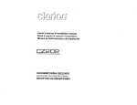
. System 88
Confidence Manual
PolyMorphic
. Systems
460 Ward Crive Santa Barbara Califomia 93111 (8051967-2351
o
This is Version V of the Confidence Manual and is meant to
accompany Version V of the Confidence Package.
See page 3 for
Confidence Package part numbers.
The software described in
this manual was created by L. G. Danczyk, F. E. Weiss and Frank
Anderson. The manual was written by L. G. Danczyk, edited by
Dr. Gerald A. Bradley, and revised by Jennifer Douglas.
This manual
is part number 810167 Copyright 1979, Interactive
Products Corporation. All rights reserved.
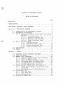
SYSTEM 88 CONFIDENCE MANUAL
Table of Contents
Page
Section-l
INTRODUCTION
•
•
CONFIDENCE PACKAGES (PART NUMBERS)
Section-2
2.1
2.2
2.3
2.4
2.5
Section 3
3.1
3.2
3.3
3.4
4.1
4.2
•
•1
• • •3
CONFIDENCE TESTING • • • . • .
• • • • • • • • 5
INTRODUCTION TO CONFIDENCE TESTING • • . . • • . 5
PREVENTIVE ' MAINTENANCE • • . . • • • • . • • . • 5
2.2.1 Running the Tests: Which Test, How often,
and Why. • • • • • • • • • . •
• 5
2.2.1.1 Confidence Test . . . . • . • . 5
2.2.1.2 Extensive Memory Test . . • . • 6
2.2.1.3 Printer Interface Test.
..7
2.2.1.4 Video Interface Test • . . . . • 7
HOW TO RUN THE TESTS • . ~ • . . . • • • . • . . 7
2.3.1 Confidence Test . • . . • . . . . 7
2.3.2 Extensive Memory Test . . . • • • 10
2.3.3 Printer Interface Test . • • . . 11
2.3.4 Video Interface Test • . • • • . 11
ENVIRONMENT. . . • • • .
. . •
• .12
POWER
•
•
REPAIR .
•
•
•
•
•
•
•
•
•
•
•
•
•
•
•
•
•
•
• 12
• • 13
HARDWARE VERSUS SOFTWARE PROBLEMS.
. • . • 13
CARD ISOLATION • • . . • . • • • • • . . • • . 14
MEMORY CHIP ISOLATION • . • • . • . • . . . . . 24
3.3.1 Common Considerations and Techniques . • 24
3.3.2 CPU Card Memory Chips. • • . . .
. 24
3.3.3 Video Terminal Interface Card . . . . . 24
3.3.4 Isolating Chips on Memory Cards • . . . 24
3.3.5 16K RAM Memory Chip Isolation . . . . . 25
3.3.6 8K RAM Memory Chip Isolation • . . . . . 27
DOUBLE-DENSITY CONTROLLER CHIP ISOLATION • . . 29
3.4.1 88/MS Double-Density Controller Chip
Isolation . . . . . . . • . . • . . . . 29
3.4.2 Double-Density 5" Chip Isolation • . . . 30
CONFIDENCE TEST . • . . . . . • . . . • . . . . 33
4.1.1 CPU Card Test . . . . . . . . . • . . . 35
4.1.2 Disk Read Test • . . . . • . . . . . . • 35
4.1.3 Memory Tests.
. . • . . . • • . . . 35
EXTENSIVE MEMORY TEST • • • ••• • • • • • • • 36
4.3
4.4
PRINTER INTERFACE TEST • • • • •
VTI TEST • • • • • • • • • •
•
• • • 36
• • • 36
Drawing s
Sequence of Test for the Confidence Test • • • • • •
34
Sequence of Test for Video Terminal Interface Test • .
. 37
Assembly-CPU Board •
• 38
•
Assembly-Video Board •
• 39
Assembly-16K RAM • • • •
• 40
8-K RAM •
. • • .
• • •
. • .41
Assembly-Double-Density 5" Disk Controller
• • • 42
Assembly-Double-Density 8" Disk Controller • • • • • • • 43
o
PolyMorphic Systems
o
System 88 Confidence Manual
Page 1
INTRODUCTION
The PolyMorphic Systems User Confidence Package lets you test
your System 88 computer regularly, so that you can be confident
that it is working well. To use it, you insert a disk into
each drive of your System 88, including each drive of your
88/MS if you have one. To run the test program, push the Load
button.
The Confidence Test segment runs, automatically upon
loading of the system. You can cause the other tests to be
executed by typing CTRL S and selecting the appropriate number
from the menu of tests. The results of the tests are displayed
on the screen and are easy to recognize.
You don't need to
know anything about computers or electronics to test your
system.
Computers are extrememly reliable and trouble-free.
There is
little that can break or get out of adjustment. The infrequent
problems that do arise can be identified in their early stages
by confidence testing, and your dealer can make repairs before
the problem has a chance to do any harm.
These confidence tests will tell you if the computer is
starting to misbehave in some way.
Beyond that, they will tell
you in some cases which particular part is about to start
causing problems, but in general they are not intended to
isolate a developing problem to a particular
electronic
component.
Once you know that a problem is developing, your
dealer can perform diagnostic tests that narrow it down to a
particul'ar item inside the system.
In order to service the System 88, most dealers keep on hand
spare parts that are known to be working.
When the dealer's
service personnel have determined which part in your system is
about to start causing problems, they
can
insert
the
appropriate spare into your system and send the defective part
to PolyMorphic Systems. We repair it and return it to the
dealer.
He then removes the spare part and replaces the
repaired part. This reduces to a minimum the time that your
system is not running.
In the case of memory chips, the dealer
can isolate the malfunction to a particular chip and replace
that chip.
In cases where it is possible to isolate a
developing
malfunction to a particular part, users with sufficient ability
can remove that part and bring it to the dealer. Some users
may even want to replace memory chips themselves, and the user
confidence package enables them to do so.
You should now check your confidence package to make sure that
you recieved the right one for your Sytem a8.
The different
confidence packages and their numbers are listed below.
In
addition to noting that your package part number
is correct,
make sure that the Confidence Disks are the right part number.
Note that if you have a System SS with an BS/MS add-on you need
Page 2
. PolyMorphic Systems
System 88 Confidence Manual
two packages, one for your
drives.
8-
drives
and
one
for
your
5-
C)
PolyMorphic Systems
o
System 88 Confidence Manual
Page 3
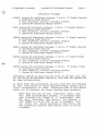
Confidence Packages
000538
(2
(1
(1
System 88 Confidence Package, 2 drive,S" Double Density
Confidence Disks 820163)
Test Connector, Printer Interface 004533)
System 88 Confidence Manual 810167)
00537 System 88 Confidence Package, 3 drive, 5" Double Density
(3 Confidence Disks 820163)
(1 Test Connector, Printer Interface 004533)
(1 System 88 Confidence Manual 810167)
000528 System 88 Confidence Package, 2 drive,S" Single Density
(2 Confidence Disks 820113)
(1 Test Connector, Printer Interface 004533)
(1 System 88 Confidence Manual 810167)
000511 System 88 Confidence Package, 3 drive,S" Single Density
(3 Confidence Disks 820113)
(1 Test Connector, Printer Interface 004533)
(1 System 88 Confidence Manual 810167)
000548 System 88 Confidence Package, 2 drive, 8" Single-Sided
(2 Confidence Disks 820171)
(1 Test Connector, Printer Interface 004533)
(1 System 88 Confidence Manual 810167)
000549 System 88 Confidence Package, 4 drive,
8" Single Sided
,(4 Confidence Disks 820171)
(1 Test Connector, Printer Interface 004533)
(1 System 88 Confidence Manual 810167)
Confidence testing is done with the cover of the main unit left
on, and should be performed regularly, even when the system has
not been malfunctioning.
In using these test procedures, you will find that the displays
on the video screen are quite straightforward, needing only a
little interpretation at times.
Tables provided in this manual
enable you to interpret the screen displays when necessary.
NOTE: Make sure you use only confidence disks
that
were made by PolyMorphic Systems.
A confidence disk
that is actually an "image" of a
factory-made disk
may give
inaccurate
test results.
For instance, a
disk IMAGEd on a drive that is out of alignment will
not
reveal
the
faulty alignment of that drive, and
may incorrectly indicate that another drive is out of
alignment.
Page 4
System 88 Confidence Manual
PolyMorphic Systems
System 88 Confidence Manual
PolyMorphic Systems
page' 5
Section 2
Confidence Testing
This section describes the confidence tests and how you use
them to make sure your system is in good operating condition.
The next section, Repair, offers suggestions on how to use
these tests to isolate a given problem to its source, whether
it be hardware or software. In most cases, users will want to
take their systems to the dealer for further
testing and
repair;
don't attempt repairs yourself unless you're sure you
can do them.
NOTE: Attempted repair of a system component, except
for
replacement of memory chips in sockets, by
unauthorized personnel voids the warranty.
The section called Technical Dis~ussion of the Tests includes a
technical discussion of each test and indicates what problems
each test can find.
Included is a hexadecimal to bit numbers
table that will help you use the condensed information provided
by the Confidence Test to isolate defective memory chips, if
you want to replace them yourself. We use these tables -- as
opposed to having the test tell you directly which memory chip
is bad
because this lets you test memory cards made by
various manufacturers.
2.2 PREVENTIVE MAINTENANCE
Preventive maintenance involves running a series of tests
regularly -- once a week or once a month, depending on the test
-- and examining the resulting screen displays, so that you
always know the current condition of the system.
Included in the descriptions of the tests below, are sample
screen displays and explanations. If the test does not even
get to the point of displaying the expected display, one of the
following three things may be happening:
1. The Confidence Disk itself is bad.
2. The system is malfunctioning
cannot even produce a display.
so
badly
that
it
3. The problem is intermittent, and so is randomly
interfering with the execution of the test.
2.2.1 Running the Tests: Which Test, How Often, and Why.
2.2.1.1 Confidence Test
The Confidence Test provides a quick way to assess the system's
Page 6
System 88 Confidence Manual
polyMorphic Systems
condition. Except for memory errors
(which it totals), the
screen display indicates whether the important component areas
of the system are good or bad.
If a cycle of the test finds a
particular area bad, that discovery is remembered: if another
part of the test or another cycle of the same part of the test
finds the same tested area good afterwards, the bad indication
is retained.
These good/bad determinations are made
by
comparing
various test results to pre-defined levels of
expected minimum performance.
It is good practice to run this test for an hour every week on
a system. If this is done, for instance, the Disk Read part of
the test can keep you informed about any · change in the
condition of the disk drives. This is important in maintaining
a library of readable disks, since a disk drive that is slowly
going out of alignment will often be able to read a disk that
it wrote yesterday, but not a disk it wrote last month.
The test presents memory errors as a number,
rather than
specifying a particular item ~s good or bad. Any number other
than 0000 indicates a problem. This test isolates memory card
problems to a lK memory block (1024 consecutive addresses).
If
a memory error occurs and you want to replace the defective
memory chip yourself, refer to the repair section to isolate
the problem to a particular chip.
Use CTRL/S
(hold down the CTRL key and hit the s key)
display a list of the tests and to make a selection.
to
The System 88 printer driver is used with the tests.
You can
get a printout telling how many errors a test has found so far
or one that provides a brief summary of errors (this may be
selected after the display of the System 88 tests). The
pr inter dr i ver cur rentl y de faul ts to null
(no output)
and
should be changed to default to your printer. Several other
printer devices are prerecorded on the confidence disk for your
use.
If you have some kind of printer not included among those
on the disk, you will have to add a device definition
corresponding to your printer (this may take quite a bit of
trial and error). See the System 88 User's Manual for more
information about the printer driver. The default device and
parameters may be viewed and changed by typing CTRL/Y and then
Printer. Of course, the write-protect tab must be removed from
the disk to edit the printer driver. After doing this, you can
restart the test by typing INITIAL or pressing the Load button.
If you select the error summary printout, you will get a
display summarizing the errors found on every
pass
of
Confidence. The error printout selection prints on the printer
all the error information that is presented on the scrolled
display that occupies the bottom four lines of the screen.
2.2.1.2 Extensive Memory Test
PolyMorphic Systems
o
System 88 Confidence Manual
Page 7
The Extensive Memory Test is a thorough worst-case test for the
memory of the System 88.
Because it is rather long,
the test
may be run once a month.
It takes about 90 minutes to run the
test once for every 16K of memory in the system.
2.2.1.3 Printer Interface Test
This test checks out the Printer Interface Card and the
communications circuitry on the CPU card.
serial
2.2.1.4 Video Interface Test
The Video
Interface Test displays all characters and graphic
symbols of the System 88 character set. Compare this display
to the correct display included in this manual.
2.3 HOW TO RUN THE TESTS
The Confidence Test runs automatically as soon as you insert
the confidence disk into the System Drive and
press the Load
button.
To run the other tests, type CTRL/S and select a test
from the list of tests displayed.
CTRL/S works only when
interrupts are enabled;
some parts of some tests disable the
interrupts so as to run without interruption.
You can return
from any test and select any other test by typing CTRL/S.
Assuming interrupts are enabled, you can also use CTRL/S to
stop any test and select another.
2.3.1 Confidence Test
Simply inserting
the confidence disk in the System Drive and
pressing Load will run the Confidence Test. The test requires
a confidence disk in every disk drive, with the write-protect
tab on each disk, to test every disk drive properly.
If a
drive contains no disk, or if its door is left open, you may
get a spurious error report.
Selecting "error printout" with this test will print the errors
of the Disk Read
test
(and
possible
loading
problems
encountered when reloading the INITIAL file).
Selecting "error
summary printout" with this test will print the summary display
on every pass of the test.
Page 8
System 88 Confidence Manual
PolyMorphic Systems
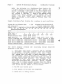
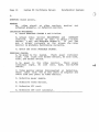
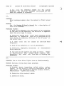
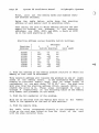
NOTE:
The following is a Confidence Test display for
a 3 drive system in good condition. The spaces for
drives 4 through 7 are blank in the Motor Speed Test
line. This is because there is no Motor Speed Test
for drives 4 through 7.
Even if the system being
tested is a 7 drive system,
these spaces will be
blank.
The word "none" will appear in all other
spaces which fall in the colums of drives that you
don't have.
o
Sample Confidence Test display for a system in good condition:
System 88 Confidence Test
V 5.0
Elapsed Time:00:00:02:43
CPU Test:good
Passes Completed: 0004
Memory Test . - Cumulative Errors:0000 Hex memory address blocks:
CP 20 30 40 50 60 70 80 90 A0 80 C0 D0 E0 F0
********************
H 1 9 h: ••• : ••• : • • • : •••.:. ••• : ••• : ••• : ••• : ••• : ••• : ••• : ••• : ••• : ••• : •
Low
: ••• : ••• : ••• : ••• : ••• : ••• : ••• : ••• : ••• : ••• : ••• : ••• : ••• : ••• :.
Disk Test -1
2
3
4
5
6
7
Motor Test:
good good good bad
bad
bad
bad
Write Protect Test: good good good
Read Results:
good good good none none none none
CTRL/S displays the confidence tests.
CTRL/Y returns to Exec
Disk Drive number 01. Cumulative errors - Soft:0000 Hard:0000
Disk Drive number 02. Cumulative errors - Soft:0000 Hard:0000
Disk Drive number 03. Cumulative errors - Soft:0000 Hard:0000
Unique Address Test.
Pattern Test.
Refresh Test.
The above display reveals
progress of the test:
the
following
things
about the
1.
Zero days, zero hours, 2 minutes, and 43 seconds
in processor
interrupt enabled time have elapsed
since the start of the main loop of the test.
When
the system runs this test, it must sometimes disable
the interrupts. While interrupts are disabled,
the
system cannot access the real-time clock, so time is
not kept during such periods.
The "Elapsed Time"
displayed
is the total
time that the test has run
while the interrupts were enabled.
Actual elapsed
test time is always somewhat greater than the figure
displayed-- how much greater depends on the number of
disk drives and the number of errors found.
2. The CPU card tested good.
3. Four passes of the test has completed.
4. There were no memory errors.
~
PolyMorphic Systems
System 88 Confidence Manual
Page 9
5. One cycle of the Disk Read Test was run on each
drive and tested good on all three drives.
6. The first three lines of the four
lines at the
bottom of the screen indicate the total number of
soft and hard errors for each disk drive the test has
accumulated since its beginning.
7. The
bottom line names the last three tests
performed in a pass of the test. When one of these
three tests is in progress, an arrow (not shown
above) points to the IK block of memory being tested
by that particular test.
8. The amount of memory in the System 88 under test
is graphically represented by the line of stars and
the two lines of colons and dots. The sample display
above indicates that there is 56K of RAM in the
system,
in addition to the 1/2 K of RAM on the CPU
card.
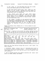
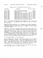
Sample Confidence Test display for a 3 drive system in poor
cO!"l.dition:
System 88 Confidence Test
CPU Test: -- RTC
V
5.0
Elapsed Time:00:00:02:43
Passes Completed: 0004
Memory Test - Cumulative Errors:0017 Hex memory address blocks:
CP ,20 30 40 50 60 70 80 90 AO BO CO 00 EO FO
*********************************************************
H 19 h: .•. : ... : •.. : 7 •• : ••• : ••• : ••• : ••• : ••• : •• 4 ••• : ••• : ••• : ••• : •••
La w : ••• : ••• : ••• : ••• : ••• A ••• : ••• : ••• : ••• : ••• : ••• : ••• : ••• : ••• : •••
7
6
4
5
Disk Test -1
2
3
bad' bad bad
Motor Test:
bad
bad
bad
bad bad
Write Protect Test: bad
bad
Read Results:
bad
bad
bad none none none none
CTRL/S displays the confidence tests.
CTRL/Y returns to Exec
Disk Drive number 01. Cumulative errors - Soft:0390 Hard:OOOl
Disk Drive number 02. Cumulative errors - Soft:OOlE Hard:OOOl
Disk Drive number 03. Cumulative errors - Soft:0192 Hard:OOOO
Unique Address Test.
Pattern Test. Refresh Test.
Below are the less obvious things that can be
above display:
said
about
the
1. Seventeen memory words at up to 17 addresses were found to
be incorrect by the two memory tests.
(Since each location is
tested more than once, more than one error can be reported from
each address.)
2. The lK address blocks that tested incorrect are'
start at 4400H, 6000H, and ACOOH.
those
that
polyMorphic Systems
System 88 Confidence Manual
Page 10
3. The data bits (0 - 7)
address blocks are:
that tested incorrect in the above lK
o
A. Bits 4, 5, and 6 in 4400H to 47FFH.
B. Bits 1 and 3 in 6000H to 63FFH.
C. Bit 6 in ACOOH to AFFFH.
This information is obtained with help from the WMemory Data
Error to Bit Number Table" at the end of the next section.
4. Disk Drive 2 Read Results is displayed bad because one hard
error was read in the first pass of the Confidence Test.
5. Disk Drive 3 Read Results is displayed bad because more than
100 soft errors were read in the first pass of the Confidence
Test. The actual number of errors found is 192H (302 decimal).
6. The RTC (real-time clock) on the CPU Card tested bad.
(This
indication is shown for display purpose only; if the RTC were
bad, the memory tests would not have been completed.)
For more information, see Section 4.
2.3.2 Extensive Memory Test
This test requires the confidence
(usually drive 1).
disk
in
the
System
Drive
Sample Extensive Memory Test Display:
System 88 Extensive Memory Test v4
Galpat Test
Elapsed= OOhOOmOO
. .. .30
. .. .40
.. ...50. ...60. . ..70.. ...80. .. .90. . . .AO.. ...BO
.. ...CO
. ...DO
. .. .EO
. . . .FO
.. ..
20
*************
Rfrsh
Bit 7
Bit 6
Bit 5
Bit 4
Bit 3
Bit 2
Bit 1
Bit 0
**********
· . . . . . . . . . . . . .
·· .. ..... ........ .. .... .. ...... . .. ..... ...... . ...... . ........ ...... .. ........ ...... . ....... .. ..... ....
· . . . . .. . .. . ... ..... ... . . . . . . .... . .. . .. . .. ... . .. ... .... . . .. ..
· . . . .. . . . . ... .. ... . . . . . . . . . ..... . . . . . .. . ... . ... . ... . ... .. ..
·· ..... .. . .. ... .. . .... . .... . .. .. ..... .. . .. .. ... . .... ..... ..... . . . .. . .
·· .• .• .• .·0.· .• .• .. .• .• .• .. .• .• .• .. .• .• .• .. .• .• .• .. .• .• .• .. .• .• .• .. .• .• .• .. .• .• .• ... .• .• .• .. .• .• .• .. .• .• .• .. .• .•
· . . . . . . . . . . . . .
· ........ ...... .. .. .... ... ...... .. ........ ...... .. ....... .... .. . ...... . ......... .... .. . .... .. .. .. ..... ....
Only "error summary printout" will work with this test. When
you choose this test, a summary is printed at the end of every
pass.
\
polyMorphic Systems
o
System 88 Confidence Manual
page 11
2.3.3 Printer Interface Test
Before selecting this test, insert the printer test plug in the
printer output port on the back of the System 88.
If the
system fails this test, see "Printer does not work" in the card
isolation section of this manual.
If the test finds nothing wrong, you will see this display:
System 88 Printer Interface Test
V 3.0
Passes completed: 0119
Total Errors:0000
Error Baud Rate:
If the test finds errors, you will see a display like this:
System 88 Printer Interface Test
V 3.0
Passes completed: 0119
Total Errors:0177
Error Baud Rate:
50
75
110
134.5
150
300
600
900
1200
1800 2400
3600
4800
7200
9600
2.3.4 Video Interfade Test
Verify the correct character set and graphic
visual inspection after selecting this test.
characters
by
If the graphics characters are displaying correctly, the upper
part of the display will look like this (white is lighted):
Page 12
System 88 Confidence Manual
polyMorphic Systems
If the symbol character set is being displayed
lower part of the display will" look like this:
correctly,
i:t8yos~nelK AlJ\)t:01TP(1TU<j> X ljJw~/++t+~"',! "#$%&' (~~+,-./0123456789:
the
;<->?
.@ABCDEFGHIJKLMNOPQRSTUVWXYZ[\] _ abcdefghlJklmnopqrstuvwxyz{ I}Selecting
"Error Printout" with this test will print out the
title of the test and the last 96 characters.
Selecting "Error
Summary Printout" will
print out only the 96 characters.
Typing
any character during this test will cause the test to
repeat.
2.4 Environment
The system should not be subjected to dust, corrosive gases, or
airborne corrosive or conductive particles.
Keep the system
within the following ranges of temperature, etc., at all times:
Operating
Ambient Temperature: I 40
I
Relative Humidity:
Maximum Wet Bulb:
1
1
1
2.5
4
Shipping
Storage
to 115 F 1-40 to 144 F 1-8
to 117 F
to
46 C 1-40 to 62 C 1-22 to 47 F
20 to 80% I
1 to 95%
l I t o 95%
78 F
No
Condensation
1
25 C
1
Power
Power specifications may be obtained from the System 88 User's
Although the system contains an EMI filter (electromagnetic interference filter), excessive line noise could still
cause errors. An isolation transformer may be used at the
power line to correct this problem.
Manu~l.
o
PolyMorphic Systems
System 88 Confidence Manual
Page 13
Section 3
REPAIR
3.1 Hardware versus Software Problems
To begin isolation of a system problem, think of the system as
consisting of four major areas, in anyone of which a problem
might exist: the user, the application or user software if any,
the system operating software, and the hardware.
It may be
clear at the outset in which area the problem lies. Or you may
have to eliminate three of the areas, one by one, on the basis
of sound verification that each of those areas is trouble-free.
Let's consider why each
tracking down a problem:
one
of them might be eliminated in
1. User error: This area cannot be completely eliminated, but
it can be minimized by reviewing what the user did and
consulting the System 88 User's Manual.
2. User software: This area can be eliminated if the program
has worked
in the past with identical System 38 hardware,
operating system software, and user procedures.
3. Operating software: This area can be eliminated if the
program · has worked before with the same operating system
so ftware.
4. Hardware failure: Successfully running the System 88 tests
can provide a hlgh level of assurance that the hardware is
working.
Since it is impossible to test every possible
sequence of system operation, this area cannot be absolutely
eliminated.
Situations in which operator error is most likely include:
Being unfamiliar with the operating system software.
Illogical, not well thought out,
user operations.
and/or
unattentive
Incorrect assumptions.
Situations in which problems with user software are most likely
incl ude:
New or changed software that has never run before.
Situations in which problems with operating software are most
likely include:
Page 14
System 88 Confidence Manual
PolyMorphic Systems
o
A system command, instruction, or proper sequence of
instructions that does not work according to the
user's manual on all System 88s.
If the same problem
occurs on an identically configured System 88, this
area can be highly suspected.
Situations in which problems
incl ude:
with
hardware
are
most
likely
A system command, instruction, or proper sequence of
instructions that does not work according to the
user's manual only on the one suspected System 88.
One aid
in narrowing down a problem is running a suspected
program on another System 88 of the same configuration.
3.2 CARD ISOLATION
The tests provided on the System 38 Confidence Disk were
designed to provide as much card isolation testing as possible
without using test equipment or having the cover off the main
unit with the power on.
This discussion is intended to isolate some of the more obvious
problems found
in the System 88 computer systems.
It is not
possible to document all possible problems, nor is it possible
to
identify ALL of the possible causes for the more common
problems. This guide should prove useful if you remember the
above exceptions and use standard,
logical troubleshooting
procedures.
Most computer problems produce obvious symptoms on the video
screen, so most of this section deals with screen symptoms. We
will list and number the symptoms first, then discuss the
probable causes.
1. Drive 3 turns on momentarily ',.,hen the system is
or the Load button is pressed.
powered
up
2. Screen is blank.
3. Random characters on sc reen.
4. No
al pha-numer ic
characters
characters will appear.
5. No graphic characters
characters will appear.
on
on
screen;
screen;
only
only
graphic
al pha- numer ic
6. Display rolls vertically.
7. Horizontal tearing of video display.
8. Steady
display
with
correct
characters,
but
a
grey,
PolyMorphic Systems
System 88 Confidence Manual
horizontal band moves slowly from bottom to top on
(cycl ic) •
Page 15
the
screen
9. Wrong characters appear at certain screen positions. This
does not include characters that the VTI is not supposed to be
able to produce (see improper dot patterns) •
10. Improper
dot
patterns.
This includes
position that has missing or extra dots.
any
character
11. Incorrect characters appear when the keyboard is used.
12. Multiple characters appear on screen when only one
pressed.
key
is
13. Characters appear on screen when no key is pressed.
14. Greek characters or other unexplainable characters appear
as part of a file name when the directory is listed.
15. The system displays the start-up messages
but does not respond to the keyboard.
and
prompt
($)
16. A program does not execute properly, and typing keys
including CTRL-Y and CTRL-Z, does not change the display.
17. Er ror messag es appear when ·the system is turned on.
18. Two 'or more dr i ve 1 ig hts turn on simul taneousl y.
19. Cassette tapes do not load or dump properly.
20. Printer does not work.
1.
SYMPTOM:
Drive 3 turns on momentarily when the
powered up or the LOAD button is pressed.
system
is
REASON:
This is not a problem; it happens on all 8813 3-drive
sy~tems.
The power-on sequence causes drive 3 to be
selected until the software selects drive 1.
Pag e 16
System 88 Confidence Manual
polyMorphic Systems
o
2.
SYMPTOM: Blank screen.
REASON:
No
video signal at video monitor, monitor
adjusted properly, or defective monitor.
not
ISOLATION PROCEDURE:
A. Check POSSIBLE CAUSES A and B below.
CONTRAST
B. Adjust video monitor BRIGHTNESS and
controls.
You should be able to obtain a bright
If you can
screen. I not, see POSSIBLE CAUSES E.
get a bright rectangle on the screen, the video
monitor is probably functioning correctly.
C. Check the other POSSIBLE CAUSES.
POSSIBLE CAUSES:
A. No power to the system.
Check power indicator
1 ight
(red light over On/O f f swi tch), AC 1 i ne cord,
fuse, and On/Off switch.
B. No power to the
indicator light, AC
switch.
video monitor.
Check power
line cord,
fuse, and On/Off
C. -Video monitor cables disconnected or defective.
Check cable from VTI to rear panel of computer and
cable from rear panel to video monitor.
D. Defective power supply.
E. Defective video monitor.
F. Defective VTI card.
G. Defective CPU card (unlikely).
PolyMorphic Systems
System 88 Confidence Manual
Page 17
3.
SYMPTOM: Random characters on screen.
REASON: Random characters stored in VTI memory.
POSSIBLE CAUSES
A. Improperly addressed VTI card.
B. Defective VTI card.
C. Defective CPU card.
D. Defective backplane.
4.
SYMPTOM:
No alpha-numeric characters on screen;
characters will appear.
only
graphic
REASON: VTI is not switching properly.
PROBABLE CAUSE: Defective VTI card.
5.
SYr..,PTOM:
No . graphic characters on screen; only alpha-numeric
characters will appear.
REASON: VTI is not switching properly
PROBABLE CAUSE: Defective VTI card.
6.
SYMPTOM: Display rolls vertically.
REASON: Loss of or inadequate vertical sync.
POSSIBLE CAUSES:
A. Video monitor not adjusted properly
(vert
B. Defective VTI card.
c.
Defective video monitor.
7.
SYMPTOM: Horizontal tearing of video display.
REASON: Loss of or inadequate horizontal sync.
hold).
Page 18
System 88 Confidence Manual
PolyMorphic Systems
POSSIBLE CAUSES:
A. Video monitor not adjusted properly (horizontal
hold). B. Defective VTI card.
C. On VTI revisions 0.0, 0.1, and 1.2: No phase 2
clOCK from CPU card, which indicates a defective CPU
or backplane.
D. Defective video monitor.
8.
SYMPTOM:
Steady display with correct characters, but a grey or
blacK horizontal band moves slowly from bottom to top
on the screen (cyclic).
REASON: positive 5 volt supply on VTI is not pure DC.
POSSIBLE CAUSES:
A. Defective VTI card.
B. Defective power supply.
9.
SYMPTOM:
Wrong
character(s)
appear
at
certain
screen
position(s) •
This does not include characters that
the VTI is not supposed to be able to produce (see
improper dot patterns) •
REASON: VTI is producing bad character(s).
ISOLATION PROCEDURE:
Use the software front panel mode or a program to
read the bad character byte. If the video memory has
the correct contents, see POSSIBLE CAUSES A&B.
If
not, it could be any of the POSSIBLE CAUSES.
If a
different hex value is displayed for the same memory
location each time you update the front panel display
by typing U, see possible cause F.
POSSIBLE CAUSES:
A. Defective VTI memory.
B. Defective VTI card.
C. Software problem.
D. Defective backplane.
E. Defective CPU card (unlikely).
o
PolyMorphic Systems
System 88 Confidence Manual
Page 19
F. If the System 88 is an upgrade from a POLY 88, it
may have a memory timing problem, which can be
eliminated with the VTI modification called for in
the upgrade manual.
10.
SYMPTOM:
Improper dot patterns.
Includes
any
character
position that has missing or extra dots. Some early
character generator ROMs do not drop the tails of
lower case letters.
RELEVANT DATA:
Each character position is a 10XlS dot matrix.
ASCII
characters are 7X9 imbedded
within
the
laXlS
character position.
Characters with extended tails
are simply imbedded lower in the 10XIS matrix.
PROBABLE CAUSE: Defective VTI card.
11.
~
SYMPTOM: Incorrect characters appear when the keyboard is used.
REASON:
Inoorrect characters reach the final sections of
VTI card.
the
POSSIBLE CAUSES:
A. Defective keyboard (most probable).
B. Defective keyboard cable.
C. See also Wrong character(s)
appear at certain
screen posi tion( s), Mul tiple characters appear on
screen when only one key is pressed, or Improper dot
patterns.
12.
SYMPTOM:
Multiple characters appear on screen
key is pressed.
when
only
one
REASON: VTI sees multiple keyboard strobes.
POSSIBLE CAUSES:
A. Holding
down key too
Systems keyboards except
auto-repeat feature.
long.
All Po 1 yMo r ph i c
Keyboard
I
have
an
Page 20
System 8a Confidence Manual
polyMorphic Systems
o
B. Defective keyboard.
c.
Electrical noise on keyboard cable (the ususal
symptom for this is Characters appear on screen when
no key is pressed) •
13.
SYMPTOM: Characters appear on screen when no key is pressed.
REASON:
VTI card sees a strobe not produced by typing or
generates an invalid interrupt.
ISOLATION PROCEDURE:
This Is almost always caused by electrical noise on
the keyboard strobe line. The keyboard cable acts
like an antenna, and an invalid strobe pulse can be
generated by electrical noise.
If this problem
occurs often enough, you can unplug
the keyboard
cable and ground the keyboard strobe input (pin 9 of
the 25 pin keyboard socket). .If spurious characters
are still generated, the problem is in the computer.
If they are not, the problem is in the keyboard or
cable.
POSSIBLE CAUSES:
A. Electrical noise.
Try inst~lling a commercial
line filter between the wall outlet and the power
cord.
B. Defective keyboard.
C. Defective VTI card.
14.
SYMPTOM:
Greek
character(s)
or
other
unexplainable
character(s) appear as part of a file name when the
directory is listed.
RELEVANT DATA:
Normally, control characters do not print on the
screen when typed from the keyboard. An exception is
when the system is in the text edit mode.
If the
control characters do not perform a control function,
they will be accepted and used but not displayed.
control character appears as a Greek character,
square
root sign, up,
left, and right arrows,
division sign, or approximately equal sign
(wavy
equal sign) when printed on the screen.
REASON:
Control
character(s)
have
been
entered as part of
PolyMorphic Systems
o
System 3S Confidence Manual
Page 21
name.
POSSIBLE CAUSES:
A. You have typed
noticing.
It did
entered.
a control
not print
character
without
on the screen when
B. Electrical noise generated a control character
when the file name was being entered. See Characters
appear on screen when no key is pressed.
15.
SYMPTOM:
The system displays the start-up messages and
($) but does not respond to keyboard.
prompt
REASON:
Keyboard information does not reach CPU card, or Exec
is ignoring the characters sent.
POSSIBLE CAUSES:
A: Keyboard not plugged into computer or plugged into
wrong socket.
B. Keyboard
interface
(sometimes called
card) cable is not plugged into VTI card.
parallel
C. Defective keyboard.
D. Defective VTI card.
E. Defective System Disk.
F. Defective memory card.
G. Defective CPU card or CPU
EPROM) •
memory
(RAM,
ROM,
or
16.
SYMPTOM:
A program does not execute properly, and typing keys,
including CTRL Y and CTRL Z, does not change the
display.
REASON:
Program is probably
interrrupts disabled.
POSSIBLE CAUSES:
A. Software problem.
caught
in
a
loop
with
the
Page 22
PolyMorphic Systems
System 88 Confidence Manual
B. See also the POSSIBLE CAUSES for The system
qisplays the start-up messages and prompt ($) but
does not respond to keyboard.
o
17.
SYMPTOM:
Error messages appear when the system is first turned
on.
REASON:
See the System 88 User's Manual for a description of
each error message.
POSSIBLE CAUSES:
A. Most error messages are the result of an oversight
on the part of the operator; the solution is apparent
when the error type is known.
B. Defective System Disk. Note: disk contents can be
destroyed by magnetism
(such as is generated by AC
line cords} or momentary failures of the AC power at
the wrong time.
c.
A 0302
alignment.
error
can
be
caused
by
bad disk head
D. 'Disk drive defective or out of adjustment.
E. Defective, improperly installed,
drive cable(s) •
or
disconnected
F. Any card in the system can cause an error.
(Order
of significance: FDC,
floppy power supply, CPU,
backplane, any other bus card that is causing bus
problems. )
18.
SYMPTOM: Two or more drive lights turn on simultaneously.
REASON: Multiple drives have been selected.
POSSIBLE CAUSES:
A. Program shunt
(sometimes called drive
select
header)
on the drive PC cards are configured for the
same dr ive. See PolyMorphic Systems drawing tl04417,
MODIFICATION - FLOPPY DISK DRIVE.
B. Defective drive control cable.
C. Defective drive.
~
7""7
PolyMorphic Systems
Page 23
System 88 Confidence Manual
D. Defective FDC card.
19.
SYMPTOM: Cassette tapes do not load or dump properly.
ISOLATION PROCEDURE:
A. Check that the recorder's volume and tone controls
are set to recommended levels.
B. Check to
properly.
see
that
all
cables
C. Run the printer interface test.
fails, see Printer does not work.
are
hooked
up
If the system
D. Check to see that JMP2 on the cassette
connected from center pad to minus.
card
is
E. On upgrades, check to see that the Byte/Poly
switch is set correctly (or correctly eliminated) •
F. Check the adjustment of R26 and R27 (see
card manual) •
cassette
G. Test the CPU USART.
H. Substitute working tape, cables, recorder, and
cassette card into the system one at a time.
POSSIBLE CAUSES:
A. User error.
B. Bad tape or tape recorder.
C. Hardware failure.
20.
SYMPTOM: Printer does not work.
ISOLATION:
A. Check cables,
switches.
printer
header,
and
printer
B. Use a printer routine that is known to be working.
C. Run the printer interface test.
If the system
fails,
the problem is probably on the CPU card or
serial I/O card. On upgrades, make sure that the K
jumper on the CPU card is connected and that the CPU
card has all necessary modifications.
Check the
jumpers on the serial I/O card.
Pag e 24
System 88 Confidence Manual
polyMorphic Systems
3.3 MEMORY CHIP ISOLATION
This section explains how to isolate a problem to a particular
memory chip and make the required repair.
Use this section
when you find memory errors.
3.3.1 Common Considerations and Techniques
To insure that the indicated chip is actually causing the
problem, it is a good practice to swap the chip with another
identical chip, predict the test results by going through the
steps below in reverse sequence, then running the test again
and seeing if in fact the problem swaps to its new location.
If the same results occur as before, chances are the problem is
elsewhere than in the chip you selected.
Since it is easy to put a chip in wrong by rotating it 180
degrees,
it is important to note the pin 1 indication (often a
notch) in one end of the ch i p and make sure it goes in exactl y
as it came out. The correct method to remove a chip by hand is
to pry out one end a little, then the other, repeating
alternately.
An
incorrect method that will almost always
result in bent pins is to try to pull the chip out by holding
it with one finger on each end of the chip.
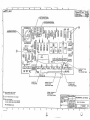
3.3.2 CPU Card Memory Chips
There are four memory chips located on the CPU card, numbered
21
through 24.
Please see the CPU card layout in the package
of drawings appended to this manual to locate these chips.
A
memory error in one of these chips will be designated by data
under one of the four marks under "CP" in the Confidence Test
memory error summary display.
The four marks from left to
right correspond directly to chip numbers 21 through 24.
The
data represented is not as important here, since each memory
chi pis use d for f 0 u r bit s 0 f a wo rd.
It
doe s i n an y cas e
represent what bits were incorrect.
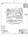
3.3.3 Video Terminal Interface Card
There are eight memory chips located on the VTI card, numbered
21 through 28. See the VTI card layout in the package of
drawings appended to this manual to locate these chips. A
memory error in one of these chips will be displayed directly
on the video screen. The program displays this in four places
on the screen and stops, so you have a good chance of getting
the message.
3.3.4 The Basic Steps for Isolating Chips on Memory Cards
There are essentially four steps to take to find the bad memory
chip after knowing the incorrect data and corresponding address
block:
o
PolyMorphic Systems
System 88 Confidence Manual
Page 25
1. Isolate the memory problem to one memory card.
2. Find the address of the memory problem relative to where all
memory on that card
is addressed.
This will isolate the
problem to a portion of the memory card.
3. Find the bit number(s) of the problem. This may be obtained
directly from the Extensive Memory Test.
Use the
following
table to
fnd the bi t number (s) from the Con f idence Test Da ta.
Memory Data Error to Bit Number Table
Data Error
I
Hex Digit ** I
0
1
2
3
4
5
6
7
8
8
9
A
·B
C
D
E
F
*
**
Low
*
Memory Bit
none
.0
1
0, 1
2
0,
I,
0,
3
0,
1,
0,
2
2
1, 2
3
3
I , 3
2, 3
0, 2, 3
I, 2, 3
0, 1, 2, 3
High
*
none
4
5
4,
6
4,
3,
4,
5
6
4
5, 6
7
4,
5,
4,
6,
7
7
5, 7
7
4, 6, 7
5, 6, 7
4, 5, 6, 7
As displayed in the Confidence Test screen display.
As displayed to the right of "low" or "high" in the
Confidence Test display.
4. Isolate the memory chip.
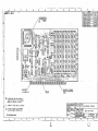
As an aid in locating a particular memory problem on memory
cards, a procedure is provided below for both the 8K RAM and
16K RAM memory cards.
3.3.5 PolyMorphic Systems 16K RAM Memory Chip Isolation.
1. Find the memory card with the memory problem.
If the System 88 contains more than one memory card,
you must
determine which card the problem is in. To do this, you must
know or figure out what part of the whole address spectrum is
made up by a particular memory card.
If the memory error
occurred within that part of the spectrum,
the problem will
usually be
in that card. The portion of the address spectrum
PolyMorphic Systems
System 88 Confidence Manual
Pag e 26
for one 16K card ends at an address 3FFFH greater than its
starting address. The starting address is the beginning of its
part of the spectrum.
o
To isolate a defective memory card:
First, pullout the memory cards and examine their address DIP
switches.
Using the starting address table below, write down the starting
addresses of each memory card in ascending order.
Then select the card in whose address section the bad memory is
located. For instance, if the starting addresses are 2000 and
6000,
a fault at 4COO is in the card with the starting address
2000.
Below is a table you can use in conjunction with the switch
positions of the DIP (dual in-line package) switch located near
the edge connector of the memory card to figure out the
starting address of the memory card.
Starting Address versus Possible Switch Settings
I
Starting I
Address I
OOOOH
1000H
2000H
3000H
4000H
5000
6000H
7000H
8000H
9000H
AOOOH
BOOOH
COOOH
OOOOH
F:OOOH
FOOOH
1
off
on
off
on
off
on
off
on
off
on
off
on
off
on
off
on
Switches
2
3
Switch Posi t ion
off
off
on
on
off
off
on
on
off
off
on
on
off
off
on
on
off
off
off
off
on
on
on
on
off
off
off
off
on
on
on
on
2.
Find the address of the memory
starting address of the card.
4
8
5, 6, 7
not used
off
off
off
off
off
off
off
off
on
on
on
on
on
on
on
on
problem
relative
to
the
This relative address will isolate the problem to one of four
areas on the memory card. From the Confidence Test summary
display of incorrect memory data, each of these areas is
represented by four stars under "20 30 40," etc. You need to
know if the error is in the first, second, third, or fourth
PolyMorphic Systems
Page 27
System 88 Confidence Manual
area from the starting address..
These areas correspond to rows
2, 3, 1, and 4 respectively of the
following
table of the
memory chip number and placement on the board.
3. Find the bit number(s)
of the problem.
This can be obtained from the Memory Data Error to Bit Number
Table in section 3.3.4.
4. Find the memory chip.·
The IC numbers in the table below correspond to
the
typical
placement of the chips on the card when looked at from the
front of the card with the edge connector down.
16K Memory Card IC Number and Placement Table
Memo ry Da ta Bi t
Address I
7
4
3
o
1
-I 5
I 6
Range * I 2
===============================================================
+2000H
I
47
44
45
46
48
49
to 2FFFH I
42
43
+OOOOH
I
. to OFFFH I
34
I
I
35
I
I
36
I
I
37
I
I
I
I
39
I
I
40
I
I
41
. +lDOOH
I
to lFFFH I
26
I
I
27
I
I
28
I
I
29
II
I 30 I
31
I
I
32
I
I
33
+3000H
I
to 3FFFH I
18
21
22
23
38
~--------------------------------------------------------------
19
20
24
* Relative to the starting address of the board-appropriate number to the card's starting address.
25
add
the
3.3.6 polyMorphic Systems 8K RAM Memory Chip Isolation.
If
the System 88 contains more than one memory card, you must
determine which card the problem is in. To do this, you must
know or
figure out what part of the whole address spectrum a
memory card occupies
in the system.
If the memory error
occurred within that part of the memory spectrum, the problem
will usually be in that card. The address region
for an 8K
card ends at an address lFFFH (eight stars) greater than its
starting address. The starting address is the beginning of it
part of the spectrum.
Below is a
table you can use in
conjunction with the switch positions of the DIP
(dual-in
. line-package)
switch located near
the edge connector of the
memory card to figure out the starting address of the memory
card.
To isolate a defective card:
Page 28
PolyMorphic Systems
System 88 Confidence Manual
First, pullout the memory cards and examine their
DIP address switches.
o
Using the table below, write down the starting
address of each memory card in ascending order.
Then select the card in whose address section the bad
memory is located.
For
instance,
if the starting
addresses are 2000, 4000, and 6000, a fault at 4COO
is in the card starting at 4000.
Starting Address versus Possible Switch Settings
Starting
Address
OOOOH
2000H
4000H
6000H
8000H
AOOOH
COOOH
EOOOH
1
Switches
3
Switch Position
on
off
on
off
on
off
on
off
2
on
on
off
off
on
on
off
off
4
[not used]
on
on
on
on
off
off
off
off
8
2. Find the address of the memory problem relative to where all
memory on that card is addressed.
This relative address will isolate the problem to one of eight
areas on the memory board.
In the Confidence Test summary
display of incorrect memory data, each of these areas is
represented by one mark under "20 30 40,· etc. You must know
what area from the starting address (first, second, third, ••• ,
eighth) the error is in. These areas correspond to rows 1
through 8
respectively of the following table of the memory
chip number and placement on the board.
3. Find the bit number(s) of the problem.
This can be obtained from the Memory Data Error to
Table in the Appendix at the end of this section.
Bit
Number
4. Find the memory chip.
The table below corresponds directly to the placement of the
chips on the card when looked at from the front of the card
with the edge connector down.
System 88 Confidence Manual
11yMorphic Systems
Page 29
8K Memory Card IC Number and Placement Table
Address I
Range * I
a
Memory Da ta Bi t
2
I 3
I 4
1
5
7
6
===:===============================~================== =========
+OOOOH
I
to 0 3FFH I
1
2
+0400H
I
to 07FFHI
9
10
+0800H
I
to OBFFH I
17
+OCOOH
I
to OFFFHI
I
I
3
4
5
6
.7
8
11
12
13
14
15
16
18
19
20
21
22
23
24
25
26
27
28
29
30
31
32
+1000H
I
to 13FFH I
33
34
35 . I
36
37
38
39
40
+1400H
I
to 17FFH I
41
42
43
44
45
46
47
48
+1800H
to IBFFH I
49
--------------------------------------------------------------I
I
I
I
50
I
51
I
I
52
I.
I
53
I
54
I
55
I
I
56
,~ ~-------------------------------------------------------------~+lCOOH I
I
I
I
II
t
I
to IFFFHI
57
t
58
t
59
t 60
t
61
I 62 t 63
I 64
------------~--------------------------------------------------
* Relative to the starting address of the card-- add the
appropriate number to the card's starting address.
3.4 DOUBLE DENSITY CONROLLER CHIP ISOLATION
The Double Density Controllers perform self-diagnosis when the
system is booted. As a part of this procedure, error messages
may be sent to the screen during the booting of the system.
These error messages are explained
in the following
two
sections.
3.4.1 88/MS Double Density Controller Chip Isolation
The following table lists the possible 88/MS Double Density
Conro1ler error messages and notes what problem they indicate.
When appropriaie the bad IC and bit numbers are provided.
Page 30
System 88 Confidence Manual
PolyMorphic Systems
0
Memory Error to Integrated Circuit Table
Message
Error
Error
Error
Error
Error
Error
Error
Error
Error
Error
Error
0380
0381
0382
0383
0384
0385
0386
0387
0388
0389
038A
Problem
Bit No. IC No.
Bad Disk Controller ROM
Self Test Failure In SDLC
(Bit 0)
Memory Error
Memory Error MS controller (Bit 1)
Memory Error MS controller (Bit 2)
Memory Error MS controller (Bit 3)
Memory Error MS controller (Bit 4)
Memory Error MS controller (Bit 5)
Memory Error MS controller (Bit 6 )
Memory Error MS controller (Bit 7)
Data Loop Failure on MS Controller
(IC33}
(IC43)
(IC22 )
(IC23)
(IC24)
(IC25)
(I C26)
(IC27 )
(IC28)
(IC29 )
The Bit indicated by a memory error message is the
first bad
bit.
There
is a possibility that other, greater bit numbers
are also bad.
Single Density systems do not generate the above messages.
Therefore there occurance on a Single Density System with an
attached 88/MS definitely indicates a
problem on the 88/MS
controller board.
However, if you have a Double Density 8813 with an 88/MS add-on
then you have two controller boards which perform boot time
self-diagnosis that can result in some of the same error
messages.
This means that you will not know which board has
the problem.
If this occurs, your dealer will be able to
determine which board is responsible for the error message.
If
it
is determined that the
faulty board
is not the 88/MS
controller but the 8813 controller board,
then the
following
section can be consulted for chip isolation instructions.
3.4.2 Double Density 5" Chip Isolation
Error message 0382 indicates a bad memory chip on the 5 u Double
Density Controller board.
When this message occurs, type a
Control Z to see front panel.
Location lC06H contains the bad
byte
(type LIC06
and the right arrow will point at the bad
byte). Use the following table to determine the bit which
corresponds to the characters provided for the bad byte.
For
instance,
if the right arrow points at byte 8A, you would
determine that Bits 1, 3, and 7 are bad.
PolyMorphic Systems
System 88 Confidence Manual
Page 31
Memory Data Error to Bit Number Table
Data Error ,
Hex Digit
, First Character' Last Character
none
none
0
0
1
2
5
1
3
4, 5
0, 1
4
6
2
5
6
7
8
9
4, 6
0,
l,
0,
3,
0,
l,
0,
2,
0,
1,
0,
4
3, 4
4, 5, 6
7
4, 7
5, 7
4, 5,
6, 7
4, 6,
5, 6,
4, 5,
A
B
C
D
E
F
7
7
7
6, 7
2
2
1, 2
3
3
l,
3
2,
2,
l,
3
3
3
2, 3
Once you have determined which bit is bad, you can consult
Bad Bit to Integrated Circuit table below.
the
Bad Bit to Integrated- Circuit
Bit I
o
1
2
3
4
5
6
7
IC
IC22
IC21
IC20
IC19
IC18
IC17
IC16
ICIS
The
following
table shows other error codes which indicate
malfunctions of the Double Density 5" controller.
System 88 Confidence Manual
Page 32
PolyMorphic Systems
Table of Double Density 5" Controller Errors
Message
problem
Error 0380
IC33 is bad
Error 038A
Phase Lock Loop tested bad
Error 030C
Controller Self-check error
Error 0307
Controller does not exist (Controller
circuitry may be malfunctioning so
severly that CPU ROMs can not tell
if it exists.
Error 0308
Checksum error
controller board
Error 030A
Controller Error
Error 030B
Head positioning mechanism on the selected
drive did not get to where it was directed
by the controller (Controller circuitry to
perform this may be at fault.)
Error 0309
Bad track 0 switch on the selected drive
(Circuitry to detect this may be at fault)
memory error on
o
PolyMorphic Systems
System 88 Confidence Manual
Page 33
Section 4
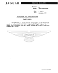
TECHNICAL DISCUSSION OF TESTS
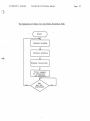
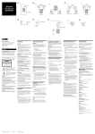
Except where the sequencing of a test is self-evident, the
discussion of each test below is followed by a block diagram
flow chart of the test program.
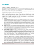
4.1 CONFIDENCE TEST
The Confidence Test is made up of two files on the disk which
depend on each other to complete.
The first file is the
INITIAL file.
It is the supervisor for all tests in addition
to containing most of the three tests below. This structure
enables Confidence to test all of the memory of the system and
also take precautions such as doing a checksum on itself before
running.
Three parts of Confidence are executed on the first pass only.
They are the checksum of the test itself, the Memory Map
routine, and the Video Memory Test. If the checksum of itself
is not correct, it will abort normal sequence and load and
execute the High Memory Test overlay, which tests memory
addressed greater than 3200H.
After these first three tests,
Confidence cycles through three other tests: the CPU card test,
the disk drives test, and the memory test.
The Memory Map routine searches the address spectrum above
IOOOH and reports the amount of memory it sees and what address
this memory starts at. This is displayed in the bottom four
lines of the screen.
A graphic representation of this is
displayed below the address blocks in the summary display.
A
star is displayed for every lK block seen addressed greater
than 2000H.
Necessary for any display is proper
Terminal Interface Card.
addressing
of
the
Video
'.
The Sequence of Tests for the Confidence Test
System Memory
0-
Cold st&rt
'U
01
Ul
Warm
Cl)
W
Test
CPU Card Test
bad
1. Checksum ROMs
~.
-Po
I
DisplOY other
tests
co
Real Time Clock
co
I-'
lSI
3. Single Step
......
I-'
W
......
IJ
Ul
Disk Dr! ves Test
bad
()
o
i.Motor Speed Test
2. Write Protect Test
3. Disk Read Test
:l
HI
.....
Load selected
0.
Cl)
test
:l
o
Cl)
Display
it
I
;3:
High RAM Test
1. Unique Mdress Test
2. Pattern Test
Stop
01
:l
c;
RWl selected
01
I-'
test
3. Refresh Test
'U
o
Memory Map
Routine
no
Increment passescompleted count;
update display
I-'
"<
::s:
o
1'"1
'd
:J'"
.....
o
CPU Card
Ul
Load in
RAM Test
Initial file
"<:
Ul
rt
Cl)
a
Ul
.-,
\J..;;
PolyMorphic Systems
o
System 88 Confidence Manual
Page 35
4.1.1 CPU Card Test
The CPU card must pass four tests before a good indication will
be displayed on the summary display.
The three ROMS are 16-bit
checksummed
individually and identified directly if incorrect.
The four memory chips are tested and identified in the memory
error summary display (see Repair section, CPU Card). The Real
Time Clock is tested
for an accuracy of 18+-3 milliseconds.
This includes allowance for 50 Hertz operation.
The failure
modes of this circuitry merit the above.
Lastly, a single-step
instruction is simulated to test the single step logic.
All of
the above except the real time clock test must work every time
for a good indication of the CPU Card Test to be displayed.
Improper operation of the
real
time clock gets displayed
directly on the summary error screen, since the problem could
be some place other than the CPU card.
If the real time clock
tested incorrect, "bad - RTC" is displayed next to "CPU Test."
4.1.2 Disk Read Test .
The Disk Read Test does three tests every pass of the
Confidence Test on each drive of a System 88.
A motor speed
test
is done and checked for a variance of no more than +-5%.
The status of the write-protect switch is read in and
reported
good
if it
is write protected.
The test then reads the last
100 sectors of each disk of the system and keeps a cumulative
total
(expressed as a hexadecimal number) of the soft and hard
errors for
each drive.
This information is scrolled and
displayed on the bottom four lines of the screen.
A bad indication will be displayed in the Read Results area of
the summary display if 100 total soft errors or one hard error
is read on a disk during a pass of the test.
This
test will try to read a disk three times (three cycles of
the Confidence Test) before giving up due to a "No disk or door
open" error.
4.1.3 Memory Tests
The memory test portion of
three separate tests.
the
Confidence
Test
is
actually
The first, a Unique Address Test, stores the least significant
byte of the address of the location into the location.
It then
checks these locations for the correct contents. The
test
is
then repeated with the most significant byte of the address.
The second
test
is a checkerboard test.
This test writes a
pattern into the odd numbered locations and the complement of
the pattern into
the even numbered locations. This is done
with three different pattern lengths which correspond to what
it takes to accomplish a checkerboard pattern in a memory card
designed with a lK, 4K, or 16K memory chip. This test is done
Page 36
System 88 Confidence Manual
polyMorphic Systems
with the data patterns of 00H, FFH, 55H, and AAH.
Memory data
errors are bit accumulated within a lK block by way of a buffer
wh ich des igna tes a word fo r each block.
Th i s buffe r
is saved
after every pass of Confidence.
The third test is a refresh test. After verifying the storage
of a number of instructions
in a 1K block,
the
test
synchronizes itself with the real-time clock and executes those
instructions.
Proper execution of these known instructions
constitutes an error-free test.
Failure of this test is
indicated by an R ~eing displayed below the corresponding lK
address block.
Because of the way the display is created,
the
R could conceivably be blotted out by a blank in a subsequent
pass of the test, or replaced by a hex digit indicating a data
error.
This test
3400H.
is
run on all memory blocks addressed greater than
Because of the way it executes, in an extreme case this test
could stop executing and cause the system to re-load, in turn
causing the test to start over.
4.2 EXTENSIVE MEMORY TEST
In addition to the three memory tests above, this test performs
a "galloping pattern" test. The galloping pattern test zeros
out a 4K memory block and then stores one different bit in each
memory chip within the memory block.
It then checks every
address of the memory chip to see if there were any changes.
The test then complements the pattern and does it again.
The
test does this to every location of the memory block and to
every memory block (except video card memory) of the system.
4.3 PRINTER INTERFACE TEST
The printer
interface card
order for you to test it.
must be configured for RS-232 in
If the test reveals a problem, and if you have the
technical
ability, make sure that the header on the printer interface
card has these pins connnected to each other: 1 to 15; 2 to 16.
This test sends data through a loop by way of a
test plug
inserted
in the printer port on the back of the System 88.
The test does this in asynchronous mode at baud rates from 50
to 9600 baud.
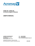
4.4 VTI TEST
This test displays all graphics
ASCII characters on the screen.
characters (twice)
and all
o
PolyMorphic Systems
System 88 Confidence Manual
o
The Sequence of Tests for the Video Interface Test
Start
Display heading
Display graphics
Display characters
Print summary
or characters
if selected
Page 37
---------- - - - - - - - - --------8
IS
7
8
---.-
:3
4
«)10hZ
)
.
~
~
~~
IjJ
~
0
~~
:.~~
@@'@
~®"n
~ ~ ~~., ~ ~ ~.
IT~/31J?~ \3
@ - --
~®
.
..
I
U
I
..
~
C\
.---. ,.
-~~~~...
at
~~
~~
\.1 .
- Q
J~~
-It
'
:!0
~.
~
•
PF
lei.
BOSO
,::1 -;
...
I ~i: 1I. ~~r. l ~~ij~~1
~>z. .!.
~
-mnDH
.
-U!DUiC
~'411
~
I
.
.,
-#DD~
.
a.It.2.~-
""S:
ROOT ROI1I .tlO
~
•
-
ItlS
~
)Q
ICII.
,1.1'.'\
~~IjI []XL! ~I~ ~UMP£R'W'
rn
'W'
FItRSIO£.
.. ~ WIR£.WRIIP
-T.jl,;
WIRE
8
JUflI'ER -,:' m F'
·2.. BUSS WII'I£
WfTH T£FUJN TlIBtIG
MOtIM) JVhlP£R
• •
•
....
A"."'L
O.!lS030
7
,.. , ... Qn,u •• u ... IC.....
S~E'::::'::'=::"
............, -
.us ono.l. lUI 10
8
~~
---~---:------_====__U_-~r-.
•
PIN O.lsazs
PIN
@
~
."~, GIal)Cf !@I.'~~' !~ J",
"6 lllf;SS WIRE.
WfTlI rEFI.PN TVGfNO
"IN O'~020
.ro
\;';')'
JU""'£R 'z.' TO
.2... BVj5 WIRE
WITH TEFLIW TVWAG
TO IS£. III1SrALLEO /lFT£ff
nOIll 5llLCJE.R t)I~r-.t)N.
I\. IC2S- :lOOT I'IGWI
';;" '
'z:
JunPER .t( .
& FM O/S/( srs ToENI'
'fI
Z
-24 avlS WIRE.
I U ' f IIIItlNIrOR RliYI
-
&INfI.a-EO-
l"
..
JIfJ, 107 ) f:!
-Ul ftt-:......
" ,' .
@~
h.UZS7)~ 1740Z51)~ 7'LI:~' ) @~
t9 --_
-ilIlD-&.a"
"'..... -___..
..
- - - - - -.- - - ----,...-------------rJ·N~ ..-~. __,
~..
44 .1
@)4J01¥
-;: fIA
. •. '
littzo
~B ~'
" '
I . .' . { . ~
If
'i'
:
:.~:~~~ ~ if rJ Q' r;) r;J' 0®~'
;
£
~@
_~
.~l~@~~l~
[j.~n~~ @1 ~.. ~. ~3r.
~n
RJ
K
&
-tiM-
.1 <@)
8
..
a
(1~
atU"IEB
POLYMORPHIC .sYSTEMS
r;3
.JlJJ~" It-II-?!.
-. -_'_"_'_~u
~"::..:..::J~~=
.."....
::::=:::.::::..---.
3
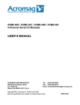
t1SSY- CPU BOARD
., -IJ
D
j'''•.•00101-2..j
-1:
IHQ"UWllllt.
~••
2
o
0. .
,.,
A
- - --
---~--~----------:----- ,-
8
8
1
o
~
15
1
2
3
4
P(JIO r.~
D
If!K
N'I(
Inll . V1f~ ilNH~1
It
~~~n ~~~~~® ~}~~~ '
~a\ ~~ ~l!l~~tY:bif~~~~ ~~
r,U
<[J
@)
~t.r"
,I
~ ,t~
i
Q:
10.
.. •~ ~Q<l
..
•
~~C
':
'
..
~.$r ~~
....
~
..
. •
_
'~'
~~
' - ,I!J,~' .~, 'A "
",' , " : " ', :' .. ' r;;
,~N
~~
~,.
- ' ...
/;\
~
'if
3 , e"
C40 ' !
" .,
D ,
,
~~
~y
!l~ '
,
D
.
Z;\!
,..
~~
. , ~~
~
~ .. IQ
.
@;>ol
~
..~~
..
~
'
i
"I'
G~ ~ t1iJ~ ~~ ~4~' ~~ ~~ ~" ~5 j'~ , ~ . ~ ~~ i- J~ ' ~
.. ; Q
I"
\,
;
"
~
""
"x
,..€i'I~~'lir.l
¥1
"I~
YI
I ,flW
I
,
. '
"
flm:---)®
,
,
;
i
!
o
.!~
~
~~
, , _,
' oJ
~~
,
Q..
\y
.. ) '
~ .,
,
Q
, '., ' d
ClJ
,C'4. " "
CI
~
,.
•
,
~l
..
~~
'4 K!..
t ,
..
'1. '
.
.
-
•
'
l;'t<2:ID<.8"'"
"
'I-
:: '
:::
'01
~;;
.
.1,
.
. t
\Ix
.
'
#
,I
J.
•
"
.
Ci'r
Clio
'iC,(\
. -
t
) CI.
t
,
~
01 ·
'
~-.
~<l
5
''''
' '"
.,J
"
.
~
t :
t
~
~:: ...
.. ~
!!
... :: i
{Il"
l"
I,
~
~.:
~@~ @~l@
,j · Im.i~l~~: :~t>\\~.:;;,~., ~~:~.i;J
\'1J
~J~o. Jl:J , ','. '"
}'. ,." .,' , :'"
'
.
~
~
!J.
I L!!!!!!!....) ~,.
,
®' . ID.~'"
~
'J'
..
..
~ ~ ..
4?f;.... ....
.,
·1IllSI·
II(
,':E,1b "Ol!' _
~
Cf!~ ~-:j
,,
:!
" -:"':J :
', ' - '
':l
a.m
:::.:I)O......-en..1f1z--
c
.
•
'
.,
-
, ~./
-
..
~,
•
-
· Lj~
N
..,
_
.," :
.. • • •
• •-
fO
.. ' .... ~ ..,..." .- '
•
.
•
I
.
' ,:
'
~ '
,
!'I .
I.; ~ •
... ··· <.:~:·;·J::. ! ,;;:·;. ~~I-: .. :·...
··~ :: L .. ··~. ,~.:,.r,ff· ·~I " ' "
•
, .
:
•
" ';'
,
•
7.1 :. , IT{!'o' ~ ,
~
Br'l
to
l.!E! '
Q
t·" , ,
.,,, {J. • :
' ~ " •i ' "
\
. , ,'
:
\
~~
I ' • • 11
lr· · ~----"'--P--' ~"
1,1
,
/
&
Ie 50CJeCT REGO .
!8 ONIIT
RI liND C!J
DISI< ,Sv.s TEM.
l~
lJE. INS,.,' UED AF'TeA? FlOlV
(l,Pt'.'NAr/ON.
12)
:IIlI. ,DEr~
Z. Nl(JO/",( PER DlVb
I~FOR
A
FOR uSE. allnl
/",,1-1(.,.
•• ~rs
.s~
5DIIZ .of£RnTIDN :
... cur
4
c,
...
n~/IC.I:.- FItONl CtiNTER PAD TO
"Z fiT JMP, J J7V1P i'"
.TMP t..
oTlMPEIC FRiWI C.evTER
TD
snH.l. /IT
P.J
PS"
.TM,..
IrcM
Po1
&.3~y.srAL~L
8£
FIN
~L'IMtM!PNIt.
_.,___...
I-
U)
liST dOfOZ,.
,S'/STEMS
"
lJJ'IClS'.!1.
• .......... Q .. u ... , .
IOltS: MIlS elldllll( ftC"11I
OlJIOZb
'_ _ _.L._
_
k
--.~ . ,,;
8
.1
8
~ '
~,
4:
3,
2
r
I
I
'.1
•
..
•
I
-
a
1
~
'!K-~
ID
I
llC
.C
'8
JUMPER II' SIIIJIUAI
US/No 'll'11J III6'IILATED
WIRE
& .,. Po:;,TION
DlP.s~ MAr BE.
jU6!lT. TIJT£b FO~ · ... POl. SIN IT'C~I
MOIINr I tJ IJPI'ER B HOLU
A
2..
In
Nl::IO/FY PER [JW6
=====:::·141 V«h~ I~a"ll
13"~-9L1.
:~~:::-n.M
Tn 8~ IN.5TALL£D .AJ::TER
FLOW 50LOl[R
1Il1O:
OPERATION.
I PI.YMtJRPHt. .n-STbVlS
nSSY-II.,I< RAVl
............... u j
.lsa~I.l'UfKl
___ -~ __ I--. ___ !.____.___ I-_ _ . e
~~~------~----i-
OO!J~OO
...".
II
-- ... - ..'4--.-.- ..--.. -..
~
([.;
1 .
o
.....
F
0'
,.,'. ,
!
·
,
' C'f, ,_,
~
~
/
~
_.
~
i.
--,,':
..
.
\
\
~
~
>:~<
,
~'~;
.....
:.:.-~,
,
......
.-
J;
..,
~
liJ
tl
-I-
)..
-~
I-
G
<:
>~
I()
".
i~
~
,. ~
. ..
!8
~II.! !'IJ
i~
~j oVl
.J
~~ 1.iJ~
.J
Cl
~3
~II\
~
)..
~C
~
~
N
I
.
t
.rt
I
i
"j
J
.()