1
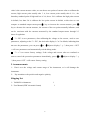
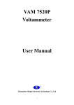
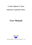
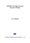
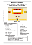
VAM 9020
Voltammeter
User Manual
Zhengzhou Minghe Electronic Technology Co., Ltd
-1-
VAM9020
voltammeter
is
a
new-type
voltammeter
which
can
measure
voltage,current,power,charging capacity and time at the same time.The voltammeter adopts
two upper and lower groups of LED nixie tubes and display measured data. During use, it
can perform flexible switching for displaying different physical quantities. Therefore, the
voltammeter is very suitable for monitoring output voltage and current and also is applicable
to occasions such as battery charge and discharge.
1. Main feature:
1、Dual display for voltage and current, and availability for switching display power, charge
capacity and time.
2 、 Flexible online calibration function, you can calibrate the voltage and current value by
yourself.
3、4-bit LED nixie tube, 3-bit measured values and one-bit unit.
2. Technical indexes
1、Two wire system input voltage range: 10V ~ 90V
Three wire system input voltage range: 0 ~ 90V
2、Output current: 0 ~ 20A
3、Display mode: 4-bit LED nixie tube, 3-bit measured values and one-bit unit
4、Display resolution :0.01V,0.01A,0.01W,0.01AH,0.01H
5、Voltage accuracy:
±1%+2 bytes
6、Current accuracy:
±2%+5 bytes
7、Measuring rate:
5 times/s
8、Size(mm):79*43*25
9、Installing hole (mm):76.5*39.2
3. The instrument structure and connection mode
In front of instrument ,there are three operate keys, two 4-bit LED nixie tubes and
operating tips, it is easy and convenient to use.
On the back of instrument there are four terminals , OUT-、+、Vext、IN-,the+ is
-2-
the public terminal of IN + and OUT + , Vext is the positive pole of an external power supply
when use three-wire system.
We can choose two-wire, three-wire system to use it. Two wire system can connect to the
meter circuit directly , three wire system needs an external power supply for the meter power
supply.
Two wire system connection diagram and the method:
Two wire system wiring diagram
The positive of the power and load connect to + , the negative pole of power connect to
IN - ,the negative pole of load connect to OUT-.
Three wire system connection diagram and the method:
Three wire system wiring diagram
Open the back cover, as shown above, use soldering iron to disconnect the short-circuit
point , external power supply use DC12V ~ 60V , Vext connect the positive pole of the
external power supply, the OUT - connect the negative pole of the external power supply.
-3-
The positive of the power and load connect to + , the negative pole of power connect to IN
- ,the negative pole of load connect to OUT-.
4. Instructions
1、Correctly connect input/output wires.
2、Make sure that the input voltage is within the scope of the instrument, after power on, the
above nixie tube display voltage value in default, the below nixie tube display current in
default.
3、Press the
button to select the above nixie tube display , press the
button to select the
below nixie tube display , it is easily to switch display the voltage (V), current (A), power
(P), capacitance (C),and time (H).
4、You can enter the debug mode in the following conditions:
1
When the measure result has a certain errors, need to be calibrated.
2
When the parameters is confused, need to restore factory settings.
The method of enter the debug mode : In the normal state, long press the < OUT >key,
when the the upper row of digital tube display "0-U ", it means that it has enter the debug
mode, short press < OUT > key again , the upper row of Nixie tubes circularly change
among 0 - U, 1 -C, 2 - ES and 3 - r,indicating that enter the different setting functions.
The method of quit the debug mode: In the debug mode ,long press < OUT > button.
5、The functions of debug mode
1
"0 - U" is calibrate the measure value of voltage, the digital tube display the voltage
value is the current measure value, we can choose two points of voltage to calibrate the
voltage, high voltage point generally take 32V, low voltage point generally take12 V, the
boundary standard point of high and low is 20V, above 20V is calibrate the high point
voltage in default, less than 20V is calibrate the low point voltage in default, at this time we
can compare to standard voltmeter,press
key to increase the voltage measure, press
key to decrease the voltage measure, the voltage of the two points mutually influence, and
can be consistent with the voltages measured by the standard voltmeter through 2-3 times of
regulation.
2
"1 - C" is calibrate the measure value of current , the digital tube display the current
-4-
value is the current measure value, we can choose two points of current value to calibrate the
current, high current point usually take 3 A, low current point usually take 0.1 A , the
boundary standard point of high and low is 2A, above 2A is calibrate the high point current
in default, less than 2A is calibrate the low point current in default, at this time we can
compare to standard ampere-meter,press
key to increase the current measure, press
key to decrease the current measure, the current of the two points mutually influence, and
can be consistent with the currents measured by the standard ampere-meter through 2-3
times of regulation.
3
"2 - ES" is save parameters, after calibrating the voltage or the current , need to save
parameters, adjusting to the "2 - ES", the nixie tube display is "-n-"in default, indicating that
not save the parameters, you can press
or
adjust to display "- y -", then press < OUT
> will save parameters and automatically exit the debug mode.
4
"3 - r" is to restore factory settings, if the voltage and current value are confused or
want to cancel the protection parameters immediately ,press
or
adjust to display "- y
-",then press< OUT > will restore factory setting.
5. Announcements
1 、 Don’t over the voltage and current range of the instrument, or it will damage the
instrument.
2、 Pay attention to the positive and negative polarity
Shipping list:
1、VAM9020 voltammeter
1
2、User Manual (PDF electronic format)
1
-5-