1
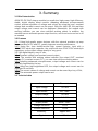
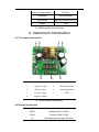
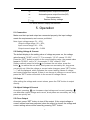
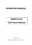
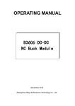
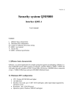
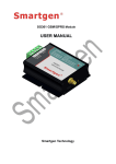
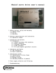
OPERATING MANUAL
400W DC-DC
CNC Boost Module
December 2013
Zhengzhou Ming He Electronic Technology Co., Ltd.
Contents
1.Contact.......................................................................................................................1
2.Inspecting Package Contens................................................................................. 1
3. Summary.................................................................................................................. 2
3.1 Brief Introduction............................................................................................2
3.2 Features.......................................................................................................... 2
3.3 Technical Data................................................................................................2
4. Instrument Introduction.......................................................................................... 3
4.1 The Module Introduction............................................................................... 3
4.3 Display Introduction....................................................................................... 3
5. Operation..................................................................................................................4
5.1 Connection......................................................................................................4
5.2 Setting Voltage & Current............................................................................. 4
5.3 Output.............................................................................................................. 4
5.4 Adjust Voltage & Current.............................................................................. 4
5.5 Close Output...................................................................................................4
5.6 Automatic Power-output Fuction................................................................. 5
6.Caution.......................................................................................................................5
7.Warranty.................................................................................................................... 5
1. Contact
Address: No.96 Rui Da Rd., Zhengzhou, China
Tel: 86-371-86106382
Fax: 86-371-86106382
Zip: 450001
E-mail: [email protected]
Website: www.mhinstek.com
2. Inspecting Package Contents
When you get a new 400W module, please inspect the instrument as follows:
2.1 Check if there is damage due to transportation
If the package is damaged, please retain them until the instrument and
accessories are tested.
2.2 Check package contents
Contents of the case are as bellows, if the content does not match with the
packing list or the instrument is damaged, please contact us.
400W DC-DC CNC boost module
1pc
User manual
1pc
2.3 Check the machine
If the machine was damaged; did not work properly or failed to pass
performance tests, please contact your dealer or our company.
1
3. Summary
3.1 Brief introduction
400W DC-DC CNC step-up module is a small size, high power, high efficiency,
stable, digital display boost module. Adopting advanced microprocessor
control, precise regulation of voltage and current by using the keys, constant
voltage and constant current can be output. With four bits LED, the real-time
output voltage and current can be displayed. Meanwhile, the module with
working indicator, you can view real-time working status. In addition, the
machine has an automatic power output function, and it can be turned on or off
as needed
3.2 Features
3.2.1 Using high-quality power devices, with the external precision op amp
loop consisting of CV and CC, greatly improves module performance;
3.2.2 Using two 1mm double-wound high current inductor, input with a
1000uF/63V electrolytic capacitor, the output with two 470uF/100V electrolytic
capacitors, so the output voltage quality is very good;
3.2.3 All-digital display, easy to use;
3.2.4 Constant voltage and constant current output;
3.2.5, The module with working status indicator (the output OUT, constant
voltage CV, constant current CC ), you can view real-time working status;
3.2.6 Adopting advanced microprocessor, output voltage and current can be
precisely regulated by the key;
3.2.7 Using four high-brightness LED, the output voltage and current can be
displayed in real time;
3.2.8 The current values of voltage and current can be saved by a key of Set;
3.2.9 The automatic power output can be set.
3.3 Technical data
Item
Parameter
Input voltage
6V~40V
Input current
15A(max)
Output voltage
8V~80V
Output current
0~9.99A
Output power
400W(max)
Voltage resolution
0.01V
Current resolution
0.01A
Efficiency
Approx 95%
Ripple
≤50mV
2
Short circuit protection
15A fuse
Connection
8500 terminals
Dimensions
86×75×63(mm)(W*H*D)
Weight
295g
3-1 400W module technical data
4. Instrument Introduction
4.1 The module Introduction
Item
Introduction
Item
Introduction
1
Negative input
5
Working indicator
2
Positive input
6
Operating buttons
3
Positive output
7
LED
4
Negative output
4-1 400W Module Introduction
4.2 Display Introduction
Display Content
Introduction
00.00
Voltage 00.00~36.00V
0.000
Current 0.000~3.00A
--0-
Automatic power output function
3
--y-
Automatic power output function(On)
--n-
Automatic power output function(Off)
----
Save parameters
Restore factory settings
4-2 400W Module Display Introduction
5. Operation
5.1 Connection
Make sure the input and output are connected properly; the input voltage
meets the requirements, and reverse prohibited.
Note: Input voltage range: 6V ~ 40V;
Output voltage range: 8V ~ 80V;
Input current range: 0A ~ 15A;
Output current range: 0A ~ 9.99A
5.2 Setting Voltage & Current
The default display is the setting value of voltage as power on, the voltage
value format is "00.00", unit is "V". For example, “12.34” means “12.34V”.
Press the “SET” button to switch to the current setting value, the current value
format is "00.00A", unit is "A", for example,”1.23A” means”1.23A”.
Setting method: press the button to increase the set value, press the
button
to reduce the set value, short press can accurately set; long press
can quickly set. After the voltage or current value changes, press “SET” button,
"----" will be displayed, which indicates the current setting values of voltage
and current have been saved. If there is no change in voltage or current value,
press the "SET" button will switch to the current or voltage values.
5.3 Output
After setting the voltage and current values, press the "OK" button to output
directly.
5.4 Adjust Voltage & Current
As output, pressing
can increase output voltage and current, pressing
can decrease output voltage and current, short press can accurately set; long
press can quickly set.
5.5 Close Output
As output, press “SET” button to turn off the output. If the output voltage or
current values have been adjusted, when the output is closed, the voltage and
current setting values will be saved by pressing “SET” button.
4
5.6 Automatic Power-output Function
Automatic power-output on/off method: Long press “OK” buttons, power to the
module, as “--0-” is displayed, release the button. If “--y-” is displayed after
releasing the button, that is the automatic power-output function on, otherwise
“--n-” is displayed, that indicates the automatic power-output function off.
6. Cautions
6.1 This module is a boost module, VOUT≥VIN 。 After power to the module, in
the absence of output, there is voltage of the output terminal, the output
terminal voltage is equal to the input voltage; if the output voltage set lower
than the input voltage, the output voltage of the output terminal is equal to the
input voltage, which is a normal phenomenon, when using the module, the
input voltage must be lower than the output voltage or the rated voltage of
electrical equipment.
6.2 When it is used to power to the high-power load, turn off the automatic
output function, connect the input and output, then press the "OK" button to
output, as the voltage rises to the set voltage, and finally turn on the load.
6.3 When it is used to charge the battery, turn off the automatic output function,
set proper charging voltage and current, connect the battery, press ”OK” to
output, and then it can charge the battery.
6.4 Fan is needed as long time high-power working.
6.5 The effective power P = input voltage×10A, the max. power of the module
reaches 400W under specified conditions, the max. output power is affected by
the input voltage and current, for example:
Input voltage is 12V: the max. output power P= 12V×10A=120W
Input voltage is 24V: the max. output power P= 24V×10A=240W
Input voltage is 40V: the max. output power P= 40V×10A=400W
6.6 Conversion efficiency: approx 85% (conversion efficiency affected by input
/ output voltage & current)
7. Warranty and service
Thank you for purchasing our products. To maximize the use of the new
product features, we recommend that you take the following steps:
1 Read safe and efficient use instruction.
2 Read the warranty terms and conditions.
We warrants to the original purchaser that its product and the component parts
thereof will be free from defects in workmanship and materials for a period of
one year from the data of purchase.
We will repair or replace, at its’ option, defective product or component parts.
Returned product must be accompanied by proof of the purchase date.
Exclusions: This warranty does not apply in the event of misuse or abuse of
5
product or as a result of unauthorized alternations or reapers. It is void if the
serial number is alternated, defaced or removed.
6