1
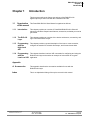
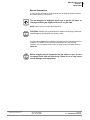
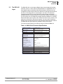
PowerDNA DIO-416
Solenoid Drive Output Layer
User Manual
8-Channel, 500 mA, Solenoid/Inductive Load Drive
Output Layer
Release 1.0
February 2007 Edition
PN Man-DNA-DIO-416-0207
© Copyright 1998-2007 United Electronic Industries, Inc. All rights reserved.
i
No part of this publication may be reproduced, stored in a retrieval system, or transmitted, in any form
by any means, electronic, mechanical, by photocopying, recording, or otherwise without prior written
permission.
Information furnished in this manual is believed to be accurate and reliable. However, no responsibility
is assumed for its use, or for any infringement of patents or other rights of third parties that may result
from its use.
All product names listed are trademarks or trade names of their respective companies.
See the UEI website for complete terms and conditions of sale:
http://www.ueidaq.com/company/terms.aspx
Contacting United Electronic Industries
Mailing Address:
611 Neponset Street
Canton, MA 02021
U.S.A.
For a list of our distributors and partners in the US and around the world, please see
http://www.ueidaq.com/partners/
Support:
Telephone:
Fax:
(781) 821-2890
(781) 821-2891
Also see the FAQs and online “Live Help” feature on our web site.
Internet Support:
Support:
Web-Site:
FTP Site:
[email protected]
www.ueidaq.com
ftp://ftp.ueidaq.com
Product Disclaimer:
WARNING!
DO NOT USE PRODUCTS SOLD BY UNITED ELECTRONIC INDUSTRIES, INC. AS CRITICAL
COMPONENTS IN LIFE SUPPORT DEVICES OR SYSTEMS.
Products sold by United Electronic Industries, Inc. are not authorized for use as critical components in
life support devices or systems. A critical component is any component of a life support device or
system whose failure to perform can be reasonably expected to cause the failure of the life support
device or system, or to affect its safety or effectiveness. Any attempt to purchase any United Electronic
Industries, Inc. product for that purpose is null and void and United Electronic Industries Inc. accepts
no liability whatsoever in contract, tort, or otherwise whether or not resulting from our or our
employees' negligence or failure to detect an improper purchase.
ii
Table of Contents
Chapter 1 — Introduction . . . . . . . . . . . . . . . . . . . . . . . . . . . . . . . . . . . . . . . . . . . . . . . . . . . . 1
1.1
1.1.1
1.1.2
1.1.3
1.1.4
Organization of this manual . . . . . . . . . . . . . . . . . . . . . . . . . . . . . . . . . . . . . . . . . . . . . 1
Introduction . . . . . . . . . . . . . . . . . . . . . . . . . . . . . . . . . . . . . . . . . . . . . . . . . . . 1
The DIO-416 Layer . . . . . . . . . . . . . . . . . . . . . . . . . . . . . . . . . . . . . . . . . . . . . 1
Programming with the High-Level API . . . . . . . . . . . . . . . . . . . . . . . . . . . . . . . 1
Programming with the Low-Level API . . . . . . . . . . . . . . . . . . . . . . . . . . . . . . . 1
1.2
The DIO-416 Layer . . . . . . . . . . . . . . . . . . . . . . . . . . . . . . . . . . . . . . . . . . . . . . . . . . . 3
1.3
Features . . . . . . . . . . . . . . . . . . . . . . . . . . . . . . . . . . . . . . . . . . . . . . . . . . . . . . . . . . . 5
1.4
Device Architecture . . . . . . . . . . . . . . . . . . . . . . . . . . . . . . . . . . . . . . . . . . . . . . . . . . . 6
1.5
Layer Connectors and Wiring . . . . . . . . . . . . . . . . . . . . . . . . . . . . . . . . . . . . . . . . . . . 7
1.6
Output Circuits . . . . . . . . . . . . . . . . . . . . . . . . . . . . . . . . . . . . . . . . . . . . . . . . . . . . . . . 9
1.7
Configuring the Circuit Breaker Function. . . . . . . . . . . . . . . . . . . . . . . . . . . . . . . . . . . 10
1.8
Configuring ADC Conversion Speed . . . . . . . . . . . . . . . . . . . . . . . . . . . . . . . . . . . . . 11
1.9
Redundancy . . . . . . . . . . . . . . . . . . . . . . . . . . . . . . . . . . . . . . . . . . . . . . . . . . . . . . . . 11
Chapter 2 — Programming with the High Level API . . . . . . . . . . . . . . . . . . . . . . . . . . . . . 12
2.1
Creating a Session . . . . . . . . . . . . . . . . . . . . . . . . . . . . . . . . . . . . . . . . . . . . . . . . . . . 12
2.2
Configuring the Resource String . . . . . . . . . . . . . . . . . . . . . . . . . . . . . . . . . . . . . . . . 12
2.3
Configuring the Timing . . . . . . . . . . . . . . . . . . . . . . . . . . . . . . . . . . . . . . . . . . . . . . . 13
2.4
Reading Data . . . . . . . . . . . . . . . . . . . . . . . . . . . . . . . . . . . . . . . . . . . . . . . . . . . . . . . 13
2.5
Cleaning-up the Session . . . . . . . . . . . . . . . . . . . . . . . . . . . . . . . . . . . . . . . . . . . . . . 13
Chapter 3 — Programming with the Low-Level API . . . . . . . . . . . . . . . . . . . . . . . . . . . . . . 14
3.1
Code Example . . . . . . . . . . . . . . . . . . . . . . . . . . . . . . . . . . . . . . . . . . . . . . . . . . . . . . 14
Appendix A — Accessories . . . . . . . . . . . . . . . . . . . . . . . . . . . . . . . . . . . . . . . . . . . . . . . . . . 19
Index
. . . . . . . . . . . . . . . . . . . . . . . . . . . . . . . . . . . . . . . . . . . . . . . . . . . . . . . . . . . . . . . . . . . 20
iii
Table of Figures
Chapter 1 — Introduction . . . . . . . . . . . . . . . . . . . . . . . . . . . . . . . . . . . . . . . . . . . . . . . . . . . 1
1-1
A DNA-DIO-416 Digital I/O Layer ..................................................................................4
1-2
DNA-DIO-416 Device Architecture ................................................................................6
1-3
DB-37 I/O Connector Pinout ..........................................................................................7
1-4
Physical Layout of DNA-DIO-416 Layer Board ..............................................................8
1-5
Diagram of DNA-DIO-416 Layer Position Jumper Settings ...........................................8
1-6
Typical Output Circuit Diagram – High-Low Pair ...........................................................9
1-7
Typical Output Circuit Diagram – High-Side ................................................................10
1-8
Typical Output Circuit Diagram – Low-Side .................................................................10
Chapter 2 — Programming with High Level API . . . . . . . . . . . . . . . . . . . . . . . . . . . . . . . . 12
None
Chapter 3 — Programming with Low Level API . . . . . . . . . . . . . . . . . . . . . . . . . . . . . . . . . 14
None
Appendix A . . . . . . . . . . . . . . . . . . . . . . . . . . . . . . . . . . . . . . . . . . . . . . . . . . . . . . . . . . . . . . . 19
None
iv
DNA-DIO-416 Layer
Chapter 1
Introduction
Chapter 1
Introduction
This document outlines the feature set and use of the DNA-DIO-416
digital output layer when used with the PowerDNA I/O Cube.
1.1
Organization This PowerDNA DIO-416 User Manual is organized as follows:
of this manual
1.1.1
Introduction
This chapter provides an overview of PowerDNA DNA-DIO-416 Solenoid/
Inductive Load Drive Output board features, accessories, and what you need to
get started.
1.1.2
The DIO-416
Layer
This chapter provides an overview of the device architecture, connectivity, and
logic of the DNA-DIO-416 layer.
1.1.3
Programming
with the
High-Level
API
This chapter provides a general description of the how to create a session,
configure the session for solenoid drive/output, and format relevant data.
1.1.4
Programming This chapter describes Low-level API commands for configuring and using the
DNA-DIO-416 layer and contains an example of code written for a typical
with the
Low-Level API application.
Appendix
A. Accessories
This appendix describes the accessories available for use with the
DNA-DIO-416 layer.
Index
This is an alphabetical listing of the topics covered in this manual.
©
Copyright
2006 all rights
reserved
United
Electronic
Industries,
United Electronic Industries, Inc.
Tel: 781-821-2890
Inc.
Tel: 781-821-2890
www.ueidaq.com
Date: 02. 14.Printed
2007 02. 14. 2007
Vers:0.5
1.0
File: DNA-DIO-416
Fax: 781-821-2891
Chap1.fm
1
DNA-DIO-416 Layer
Chapter 1
Introduction
Manual Conventions
To help you get the most out of this manual and our products, please note that
we use the following conventions:
Tips are designed to highlight quick ways to get the job done, or
reveal good ideas you might not discover on your own.
NOTE: Notes alert you to important information.
CAUTION! advises you of precautions to take to avoid injury, data loss,
and damage to your boards or a system crash.
Text formatted in bold typeface generally represents text you should be entered
verbatim. For instance, it can represent a command, as in the following
example: “You can instruct users how to run setup using a command such as
setup.exe.”
Before plugging any I/O connector into the Cube or Layer, be sure
to remove power from all field wiring. Failure to do so may cause
severe damage to the equipment.
©
Copyright
2006 all rights
reserved
United
Electronic
Industries,
United Electronic Industries, Inc.
Tel: 781-821-2890
Inc.
Tel: 781-821-2890
www.ueidaq.com
Date: 02. 14.Printed
2007 02. 14. 2007
Vers:0.5
1.0
File: DNA-DIO-416
Fax: 781-821-2891
Chap1.fm
2
DNA-DIO-416 Layer
Chapter 1
Introduction
1.2
The DIO-416
Layer
The DNA-DIO-416 is an 8-channel Digital Output Layer designed for driving
solenoids, motors, or other inductive loads attached to a PowerDNA Cube. It
has 8 digital outputs controlled by field-effect transistors (FETs) that can be
configured to provide output control for 8 channels on both high and low sides of
the load, or 8 channels each on just the high or low sides. The board has
redundant support FETs on every channel and also provides overvoltage
(kickback) and overcurrent protection on every channel. Output current monitors
(0.5% accuracy) can be configured to trigger automatic shutdown on overload,
detect short/open output circuits, and to confirm the state of every channel. The
maximum current drive is 500 mA per channel. You can set the current and
duration of an overload (as short as 10 mS) required to shut down each channel.
The DNA-DIO-416 layer requires an external 10-55V power source.
The technical specifications for the DIO-416 layer are listed in Table 1-1.
Table 1-1 DNA-DIO-416 Technical Specifications
p
Number of channels
Drive Capacity
Output Rate
Output Protection
Circuit Breaker:
Current limit
Closing time
Current Monitor:
Resolution
ADC Speed
Sense Resitor
Over-current Limit
Under-current Limit
Accuracy
Noise
Interrupts (maskable)
Limit Override
Power Requirements (VCC)
Power Consumption
Isolation
Physical Dimensions
Operating Temp. Range
Operating Humidity
©
Copyright
2006 all rights
reserved
United
Electronic
Industries,
United Electronic Industries, Inc.
Tel: 781-821-2890
Inc.
16 digital outputs
(8 high- and 8 low-side)
500mA per channel continuous max;
1A per channel max peak (1 sec max)
125Hz per channel max
±90V peak; 2kV ESD
50mA - 1A (user-programmable)
200-500ms (autorestart)
24-bit ADC
0.6 to 293 Hz
0.025Ý
0-2A
0-2A
0.5% of full scale
< 1mA
2 per channel (over/under-current)
programmable per channel
10-55V external source
1.5W no load, 3.5W at max load
350Vrms
3.875” x 3.875” (98 x 98 mm)
Tested -40 to 85°C
90%, non-condensing
Tel: 781-821-2890
www.ueidaq.com
Date: 02. 14.Printed
2007 02. 14. 2007
Vers:0.5
1.0
File: DNA-DIO-416
Fax: 781-821-2891
Chap1.fm
3
DNA-DIO-416 Layer
Chapter 1
Introduction
Figure 1-1 is a photo of the DNA-DIO-416 Layer board
IRQ Jumpers (Do not change)
Layer Position Jumpers
(see Figure 1-5)
120-pin DNA
bus connector
Power Connector
DB-37 (female)
37-pin I/O connector
Figure 1-1 A DNA-DIO-416 Digital I/O Layer
©
Copyright
2006 all rights
reserved
United
Electronic
Industries,
United Electronic Industries, Inc.
Tel: 781-821-2890
Inc.
Tel: 781-821-2890
www.ueidaq.com
Date: 02. 14.Printed
2007 02. 14. 2007
Vers:0.5
1.0
File: DNA-DIO-416
Fax: 781-821-2891
Chap1.fm
4
DNA-DIO-416 Layer
Chapter 1
Introduction
1.3
Features
The main features of the PowerDNA DNA-DIO-416 Solenoid Drive Output Layer
are:
•
•
•
•
•
•
•
•
•
•
•
•
•
•
•
•
•
•
•
•
•
©
Copyright
2006 all rights
reserved
United
Electronic
Industries,
United Electronic Industries, Inc.
Tel: 781-821-2890
Inc.
16 digital outputs configured either as 8 high-low pairs or 8 High-side
and 8 Low-Side channels
500 mA per channel maximum current drive
125 Hz per channel maximum output rate
Ideal for driving solenoids, motors, or other inductive loads
FET transistors for high- and low-side outputs
Inductive load kickback protection on every high-low channel pair
Resettable overload circuit breaker function on every channel
Output current monitoring (0.5% accuracy, 24-bit resolution) for short/
open circuit and output state detection
Requires external 10-55Vpower source (1.5W no load, 4.5W max load)
“Power Good” monitor – indicates VCC >= 10V
Programmable enable DC/DC control (emergency shutoff)
Redundancy support diodes on every channel
Over- and under-current monitoring with programmable delay FET
circuit breaking on every channel
Auto-enable option, selectable per channel, attempts to restore disabled
channel
Interrupt on over- and under-current conditions
Current monitoring user-programmable from 50mA - 2A
Default limit is 1000 mA, default disconnect time is 10-15mS
Layer survives output circuit shorts with impedances of 3 ohms or more
SYNC interface support
Clock output/trigger input provided
Guaranteed output OFF state on initial power-up, external power OFF,
internal power OFF, and overload detected
Tel: 781-821-2890
www.ueidaq.com
Date: 02. 14.Printed
2007 02. 14. 2007
Vers:0.5
1.0
File: DNA-DIO-416
Fax: 781-821-2891
Chap1.fm
5
DNA-DIO-416 Layer
Chapter 1
Introduction
The DNA-DIO-416 Layer has 8 digital outputs (8-high/low channels configured
as current sources). There are two sigma-delta ADCs, one for high-side circuits,
and one for low-side circuits, that run independently. A block diagram of the
board is shown in Figure 1-2.
HIGH-SIDE OUTPUTS
DOut (8)
FET
Transistor
DOut (8)
FET
Transistor
Overvoltage Protection
Digital I/O Connector
Power In
DGND
Current
Monitor
Current
Monitor
Sense
Resistor
32-bit 66-MHz bus
DC/DC
Control Logic
Sense
Resistor
VCC
Optical Isolation
Block Diagram:
Optoisolators
Device
Architecture
Optoisolators
1.4
DC/DC
LOW-SIDE OUTPUTS
Optoisolator
Figure 1-2 DNA-DIO-416 Device Architecture
Note that the I/O part of the layer is isolated from the logic interface by isolation
transformers and that overload protection is provided on all inputs and outputs.
©
Copyright
2006 all rights
reserved
United
Electronic
Industries,
United Electronic Industries, Inc.
Tel: 781-821-2890
Inc.
Tel: 781-821-2890
www.ueidaq.com
Date: 02. 14.Printed
2007 02. 14. 2007
Vers:0.5
1.0
File: DNA-DIO-416
Fax: 781-821-2891
Chap1.fm
6
DNA-DIO-416 Layer
Chapter 1
Introduction
1.5
Layer
Connectors
and Wiring
The pinout of the DB-37 37-pin female connector for the DNA-DIO-416 Layer
board is shown in Figure 1-3.
DB-37 (female)
37-pin connector:
VCC
DGND
VCC
VCC
VCC
VCC
RESERVED
DOUT15
DOUT14
DOUT12
DOUT11
DOUT9
DOUT8
DOUT6
DOUT5
DOUT3
DOUT2
DOUT0
37
36
35
34
33
32
31
30
29
28
27
26
25
24
23
22
21
20
19
18
17
16
15
14
13
12
11
10
9
8
7
6
5
4
3
2
1
VCC
VCC
DGND
VCC
DGND
VCC
DGND
RESERVED
DGND
DOUT13
DGND
DOUT10
DGND
DOUT7
DGND
DOUT4
DGND
DOUT1
DGND
High-Side: DOUT0, DOUT2, DOUT4,
DOUT6, DOUT8, DOUT10,
DOUT12, DOUT14
Low-Side: DOUT1, DOUT3, DOUT5,
DOUT7, DOUT9, DOUT11,
DOUT13, DOUT15
Note: Connect external power
source to VCC pins. All VCC and
DGND pins should be used to
supply external power.
Figure 1-3 DB-37 I/O Connector Pinout
Note that the DIO-416 outputs are numbered from DOut0 through DOut15.
Also note the location of the nine VCC pins. Power must be supplied to the layer
by connecting an external 10-55V power source directly to the VCC pins or
indirectly through the VCC pins on a DNA-STP-37 terminal panel connected to
the 37-pin I/O connector on the board.
When power is provided to the layer, the RDY LED on the PowerDNA Cube
turns on. When no power is supplied, the RDY LED is off, and the DNA-DIO-416
layer cannot operate.
The only valid channel pairs are Channels 1and 2, 2 and 3, 4 and 5,
6 and 7, 8 and 9, 10 and 11, 12 and 13, 14 and 15. Use of any other
channel pair connections may cause severe damage to the
equipment because kickback protection diodes will not be present.
Before plugging any I/O connector into the Cube or Layer, be sure
to remove power from all field wiring. Failure to do so may cause
severe damage to the equipment.
The board does not have reverse polarity protection because of
space constraints. To prevent damage, use extreme caution in
connecting power to the layer.
©
Copyright
2006 all rights
reserved
United
Electronic
Industries,
United Electronic Industries, Inc.
Tel: 781-821-2890
Inc.
Tel: 781-821-2890
www.ueidaq.com
Date: 02. 14.Printed
2007 02. 14. 2007
Vers:0.5
1.0
File: DNA-DIO-416
Fax: 781-821-2891
Chap1.fm
7
DNA-DIO-416 Layer
Chapter 1
Introduction
1
2
3
4
5
6
7
8
9
10
11
12
13
14
15
16
DNA 120-pin Bus Connector
J1
Factory Use Only
See Figure 1-5 for
jumper locations for
setting layer position.
Power
Connector
DB-37 I/O Connector
External Circuits
Figure 1-4. Physical Layout of DNA-DIO-416 Layer Board
1.5.0.1
Jumper
Settings
A diagram of the jumper block is shown in Figure 1-5. To set the layer
position jumpers, place jumpers as shown in Figure 1-5.
NOTE: Since all layers are assembled in Cubes before shipment to a customer,
you should never have to change a jumper setting unless you change a
layer from one position to another in the field.
Jx Pins
I/O 1
Layer’s Position as marked on the Faceplate*
I/O 2
I/O 3
I/O 4
I/O 5
I/O 6
9-10
11-12
13-14
15-16
* All I/O Layers are sequentially enumerated from top to the bottom of the Cube
- Open
- Closed
Figure 1-5. Diagram of DNA-DIO-416 Layer Position Jumper
Settings
©
Copyright
2006 all rights
reserved
United
Electronic
Industries,
United Electronic Industries, Inc.
Tel: 781-821-2890
Inc.
Tel: 781-821-2890
www.ueidaq.com
Date: 02. 14.Printed
2007 02. 14. 2007
Vers:0.5
1.0
File: DNA-DIO-416
Fax: 781-821-2891
Chap1.fm
8
DNA-DIO-416 Layer
Chapter 1
Introduction
1.6
Output
Circuits
Each output circuit is built as shown in Figure 1-6.
+50VDC
To ADC
(Current
Monitor)
RH0
HSCH1
HSCH1
240
CA0
0.022uF
CB0
0.022uF
HSCH0
-5VI
HSCH0
RSH0
0.025 Ohm/WSL0805R0250FEA
RA0
240
RC0
D_OUT0
D_OUT0
3
100K
Q0B
4
RI0
RE0
10K FDS4559/NC(Q2)
FET
56K
5
6
DA0
DOUT0
DOUT0
DFLS160 1A/60V
Redundancy
Support
Diodes
User
Load
DB0
DFLS160 1A/60V
DC0
DOUT1
DOUT1
7
8
DFLS160 1A/60V
FET Q0A
FDS4559/PC(Q1)
D_OUT1
D_OUT1
RJ0
RF0
56K
2
10K
1
RD0
100K
LSCH1
To ADC
(Current
Monitor)
LSCH1
RB0
240
CC0
1uF
DGND
LSCH0
CD0
1uF
LSCH0
RSL0
0.025 Ohm/WSL0805R0250FEA
RG0
240
DGND
Figure 1-6 Typical Output Circuit Diagram – High-Low Pair
Because of inherent imbalances in components in the circuit of Figure 1-6, a
small current is always flowing from VCC to ground through the 0.025 ohm
sense resistors. This produces a voltage that is monitored by the two current
sensing ADCs. If the current falls below a programmed minimum, this indicates
a possible fault such as an open circuit. An interrupt is then enabled.
Similarly, an overcurrent in the ON state indicates a short or overload condition,
which generates an interrupt and can cause the circuit to be shut down, if so
configured.
Figure 1-7 shows a typical High-Side output circuit. Its function is similar to that
of Figure 1-6, except that it only uses the high-side FET. Figure 1-7 shows a
typical Low-Side output circuit, using only the low-side FET.
©
Copyright
2006 all rights
reserved
United
Electronic
Industries,
United Electronic Industries, Inc.
Tel: 781-821-2890
Inc.
Tel: 781-821-2890
www.ueidaq.com
Date: 02. 14.Printed
2007 02. 14. 2007
Vers:0.5
1.0
File: DNA-DIO-416
Fax: 781-821-2891
Chap1.fm
9
,(-**#',('&,(*
DNA-DIO-416 Layer
Chapter 1
Introduction
1
* '+&+,(*
-,&$%
-,0
#"-'" '!0&'$
-))(*,&("#+
#.#*+#
-**#',
*(,#!,&('
+#*
( "
-,1
DGND
Figure 1-7. Typical Output Circuit Diagram – High-Side
-,0
10-55V
DC
#"-'" '!0&'$
-))(*,&("#+
#.#*+#
-**#',
*(,#!,&('
+#*
( "
-,1
* '+&+,(*
-,(/
,(-**#',('&,(*
1
Figure 1-8 Typical Output Circuit Diagram – Low-Side
1.7
Configuring
the Circuit
Breaker
Function
©
Copyright
2006 all rights
reserved
United
Electronic
Industries,
United Electronic Industries, Inc.
Tel: 781-821-2890
Inc.
Referring to the circuit of Figure 1-6, the voltages from both high and low side
current sensing resistors are fed to the two ADCs. The ADC outputs are then
processed in the logic to perform a virtual circuit breaker function. The outputs
are first compared to preset limits. If they exceed the limits, the FETs are turned
OFF and the output circuit is shut down. Depending on how the channel is
configured, the shutdown may either be immediate or delayed by a
programmable time or by a cumulative number of detected faults.
Tel: 781-821-2890
www.ueidaq.com
Date: 02. 14.Printed
2007 02. 14. 2007
Vers:0.5
1.0
File: DNA-DIO-416
Fax: 781-821-2891
Chap1.fm
10
DNA-DIO-416 Layer
Chapter 1
Introduction
The circuit breaker function can also be configured for either User Re-enable
(default) or for Auto Re-enable. The user-re-enable mode requires a write
operation to re-enable output on the disabled channel. The auto-re-enable mode
attempts to restore the channel after a 1 second (default) delay. If an overcurrent
is detected on restart, the channel is disabled again and the re-enable attempt
is repeated. The re-enable time interval is user programmable.
1.8
Configuring
ADC
Conversion
Speed
The speed and resolution of the ADC are user-programmable in the range from
0.6 to 293 Hz. Refer to the section marked “optional” in the code example in
Chapter 3, page 17, for more detail on setting ADC speed and resolution.
The default value for the ADC speed is 110 Hz, which corresponds to 13 Hz per
channel because of overhead. Slower speed produces more accurate results
but increases circuit breaker disconnect time, as shown in the table below.
Circuit minimum breaker reaction, ms
Measured
Nominal channel- Actual
aggregate
channel
ADC
speed,Hz delay, uS speed, Hz
3520
1760
880
440
220
110
55
27.5
13.75
6.875
634
912
1470
2600
4860
9400
18300
36600
72000
148000
1577.29
1096.49
680.27
384.62
205.76
106.38
54.64
27.32
13.89
6.76
VIn full scale,mV
LSB, full scale
mV/LSB
uV/LSB
nV/LSB
1.9
Per
channel
rate, Hz
50
8388608
5.96046E-06
0.005960464
5.960464478
Redundancy
197.16
137.06
85.03
48.08
25.72
13.30
6.83
3.42
1.74
0.84
Measured Measured Measured
4
3
2
noise, uV noise, mA
Immediate consecutive consecutive consecutive noise,
Ain
LSB, p-p Vin
samples
samples
samples
decision
5.07
7.30
11.76
20.80
38.88
75.20
146.40
292.80
576.00
1184.00
10.14
14.59
23.52
41.60
77.76
150.40
292.80
585.60
1152.00
2368.00
Shunt resistor, Ohm
Full scale current, uA
uA/LSB
15.22
21.89
35.28
62.40
116.64
225.60
439.20
878.40
1728.00
3552.00
20.29
29.18
47.04
83.20
155.52
300.80
585.60
1171.20
2304.00
4736.00
3857
3584
2560
2048
896
768
592
544
256
200
22.98951
21.3623
15.25879
12.20703
5.340576
4.577637
3.528595
3.242493
1.525879
1.192093
5.481127
5.09317
3.637979
2.910383
1.273293
1.091394
0.841283
0.77307
0.363798
0.284217
0.025
2000000 Note: typical reaction of the circuit breaker is
~ 50% longer then minimal
0.23841858 Maximum reaction time is 2x minimal
Increased system reliability is ensured by using the High-Low Side Pair circuit
for a given channel as illustrated in Figure 1-6. As shown in the figure, a
malfunction in one the FETs or side circuits will not prevent the other FET from
disabling the circuit when needed. The current sensing in the good side still
functions and the circuit breaker function will still operate safely.
Note that this feature is not valid when High-Side only (Figure 1-7) or Low-Side
(Figure 1-8) only circuits are configured.
©
Copyright
2006 all rights
reserved
United
Electronic
Industries,
United Electronic Industries, Inc.
Tel: 781-821-2890
Inc.
Tel: 781-821-2890
www.ueidaq.com
Date: 02. 14.Printed
2007 02. 14. 2007
Vers:0.5
1.0
File: DNA-DIO-416
Fax: 781-821-2891
Chap1.fm
11
DNA-DIO-416 Layer
Chapter 2
Programming with the High Level API
Chapter 2
Programming with the High Level API
This section describes how to control the PowerDNA DIO-416 with UEIDAQ’s
high-level API, called Framework.
Framework is object oriented; its objects can be manipulated in the same manner from a wide range of development environments such as Visual C++, Visual
Basic or LabVIEW.
The following section focuses on the C++ API, but the concept is the same no
matter what programming language you use.
Please refer to the “UeiDaq Framework User Manual” to get more information on
using other programming languages.
2.1
Creating a
Session
The Session object controls all operations on your PowerDNA device. Therefore, the first task is to create a session object:
CUeiSession session;
2.2
Configuring
Framework uses resource strings to select which device, subsystem, and chanthe Resource nels to use within a session. The resource string syntax is similar to a web URL:
String
<device class>://<IP address>/<Device Id>/<Subsystem><Channel list>
For PowerDNA, the device class is pdna.
As an example, the following resource string selects digital output channels
0,1,2,3 on device 1 at IP address 192.168.100.2:
"pdna://192.168.100.2/Dev1/D0:3"
NOTE: In Framework, a digital channel corresponds to a physical port on the
device. Note that you cannot configure a session only to access a
subset of lines within a digital port.
//Configure session to write to port 0 on device 1
do_session.CreateDOChannel("pdna://192.168.100.2/Dev1/Do0");
NOTE: Sessions are unidirectional. If your device has both input and output
ports or has bidirectional ports, you need to configure two sessions: one
for input and one for output.
©
Copyright
2006 all rights
reserved
United
Electronic
Industries,
United Electronic Industries, Inc.
Tel: 781-821-2890
Inc.
Tel: 781-821-2890
www.ueidaq.com
Date: 02. 14.Printed
2007 02. 14. 2007
Vers:0.5
1.0
File: DNA-DIO-416
Fax: 781-821-2891
Chap2.fm
12
DNA-DIO-416 Layer
Chapter 2
Programming with the High Level API
2.3
Configuring
the Timing
You can configure the DIO-416 to run in simple mode (point by point), buffered
mode (ACB mode), or Dmap mode.
In simple mode, the delay between samples is determined by software on the
host computer.
In buffered mode, the delay between samples is determined by the DIO-416 onboard clock.
The following sample shows how to configure the simple mode. Please refer to
the “UeiDaq Framework User’s Manual” to learn how to use the other timing
modes.
di_session.ConfigureTimingForSimpleIO();
2.4
Reading Data Reading data from the DIO-416 is done by using a reader object.
The following sample code shows how to create a scaled reader object and use
it to read samples.
// Create a reader and link it to the session’s
//stream
CUeiDigitalReader reader(di_session.GetDataStream());
// read one scan, the buffer must be big enough to
//contain one value per channel
uInt16 data;
reader.ReadSingleScan(&data);
2.5
Cleaning-up
the Session
The session object cleans itself up when it goes out of scope or when it is
destroyed. However, you can manually clean up the session (to reuse the object
with a different set of channels or parameters) by entering:
do_session.CleanUp();
©
Copyright
2006 all rights
reserved
United
Electronic
Industries,
United Electronic Industries, Inc.
Tel: 781-821-2890
Inc.
Tel: 781-821-2890
www.ueidaq.com
Date: 02. 14.Printed
2007 02. 14. 2007
Vers:0.5
1.0
File: DNA-DIO-416
Fax: 781-821-2891
Chap2.fm
13
DNA-DIO-416 Layer
Chapter 3
Programming with the Low-Level API
Chapter 3
3.1
Programming with the Low-Level API
Code
Example
The following is an example of code used for a DNA-DIO-416 Layer.
//==================================================================================
//
// NAME:
Sample416.c
//
// DESCRIPTION:
//
//
Test DIO-416 specific commands
//
// NOTES:
This example utilizes a single DIO-416 layer.
//
// -------------------------------------------------------------------------------//
//
Copyright (C) 2006 United Electronic Industries, Inc.
//
All rights reserved.
//
United Electronic Industries Confidential Information.
//
//============================================================================
#include <stdio.h>
#include <signal.h>
#ifdef _WIN32
#include <winsock2.h>
#include <conio.h>
#else
#include <netinet/in.h>
#include <unistd.h>
#endif // _WIN32
#include "PDNA.h"
/********************************* IMPORTANT NOTE *************************
Before this example can be tested on your network, you have to set up IP address
of the cube (IOM_IPADDR) and device number (DEVN) of the layer you intend to use.
Make sure that IP address of the cube lies within network mask defined in your
Ethernet interface settings.
**************************************************************************/
/* BEGIN CUSTOM CONFIGURATION */
#define IOM_IPADDR0
#define DEVN
#define TOTALSCANS
"192.168.100.2"
0
0
/* END CUSTOM CONFIGURATION */
#define TIMEOUT_DELAY
#define RETRY_ATTEMPTS
2000
10
// milli seconds
// END Customizing defines
#define EVENT_TIMEOUT
©
Copyright
2006 all rights
reserved
United
Electronic
Industries,
United Electronic Industries, Inc.
Tel: 781-821-2890
Inc.
500
// how long to wait for events to happen
Tel: 781-821-2890
www.ueidaq.com
Date: 02. 14.Printed
2007 02. 14. 2007
Vers:0.5
1.0
File: DNA-DIO-416
Fax: 781-821-2891
Chap3.fm
14
DNA-DIO-416 Layer
Chapter 3
Programming with the Low-Level API
#define UPDATE_PERIOD
50
int stop;
// -// Handler for SIGINT
//
void handler(int sig)
{
stop = 1;
}
//
// ----------------- main routine ----------------------------//
#define OVERCURRENTLIMIT (0.505)
#define UNDERCURRENTLIMIT (-0.01)
int main(int argc, char* argv[]) {
int error_found = 0;
int hd0 = 0;
int i, ret;
pDQE pDqe = NULL;
pDQBCB pBcb = NULL;
uint32 dataout,datain;
DQRDCFG *DQRdCfg = NULL;
int timeout = EVENT_TIMEOUT;
int datarcv = 0;
int packetlost = 0;
int errorsallowed = RETRY_ATTEMPTS; // maximum errors allowed at a time
DQDIO416DATAIN data416;
DQDIO416DATAOUT data416out = {0,0,0,0,0,0,0,0,0,0,0,0,0,0,0,0,0,0};
double float416[DQ_DIO416_CHAN];
#ifndef _WIN32
DqInitDAQLib();
#endif
signal(SIGINT, handler);
// open communication with IOM and receive IOM crucial identification data
if ((ret = DqOpenIOM(IOM_IPADDR0, DQ_UDP_DAQ_PORT, TIMEOUT_DELAY, &hd0,
&DQRdCfg)) < 0) {
printf("\nError In Initializing Communication with IOM");
return -1;
}
if (DQRdCfg == NULL) {
printf("\nError in receiving the response for Echo Command");
error_found = 1;
goto finish_up;
}
printf("ipaddr = %d.%d.%d.%d\n",
(DQRdCfg->ipaddr & 0xff000000)>>24,
(DQRdCfg->ipaddr & 0x00ff0000)>>16,
©
Copyright
2006 all rights
reserved
United
Electronic
Industries,
United Electronic Industries, Inc.
Tel: 781-821-2890
Inc.
Tel: 781-821-2890
www.ueidaq.com
Date: 02. 14.Printed
2007 02. 14. 2007
Vers:0.5
1.0
File: DNA-DIO-416
Fax: 781-821-2891
Chap3.fm
15
DNA-DIO-416 Layer
Chapter 3
Programming with the Low-Level API
(DQRdCfg->ipaddr & 0x0000ff00)>>8,
(DQRdCfg->ipaddr & 0x000000ff));
printf("model
= %04x\n", DQRdCfg->model);
printf("sernum = %07d\n", DQRdCfg->sernum);
printf("mfgdate = %x/%x/%x\n", (DQRdCfg->mfgdate
(DQRdCfg->mfgdate
(DQRdCfg->mfgdate
printf("caldate = %x/%x/%x\n", (DQRdCfg->caldate
(DQRdCfg->caldate
(DQRdCfg->caldate
&
&
&
&
&
&
0xff000000)>>24,
0xff0000)>>16,
0xffff));
0xff000000)>>24,
0xff0000)>>16,
0xffff));
for (i = 0; i < DQ_MAXDEVN; i++) {
if (DQRdCfg->devmod[i]) {
printf("Model: %x Option: %x\n", DQRdCfg->devmod[i], DQRdCfg->option[i]);
} else {
break;
}
}
for (i = 0; i < 16; i++) {
if ((ret = DqAdv416SetLimit(hd0, DEVN, i, OVERCURRENTLIMIT)) < 0) {
printf("\nError in DqAdv416SetLimit()");
error_found = 1;
goto finish_up;
}
}
for (i = 16; i < 32; i++) {
if ((ret = DqAdv416SetLimit(hd0, DEVN, i, UNDERCURRENTLIMIT)) < 0) {
printf("\nError in DqAdv416SetLimit()");
error_found = 1;
goto finish_up;
}
}
// -----------------------------------------------------------------------// OPTIONAL PART - get all possible data from the 416
if ((ret = DqAdv416GetAll(hd0, DEVN, &data416, (double*) float416)) < 0) {
printf("\nError in DqAdv416GetAll()");
error_found = 1;
goto finish_up;
}
printf("cfg=%08x\n", data416.cfg);//disconnection mode configuration
printf("port0out=%08x\n", data416.port0out); //last value written to the output
printf("adcsts=%08x\n", data416.adcsts);
// ADC status and speed selected
printf("port0ocs=%08x\n", data416.port0ocs); // Overcurrent status
printf("port0ucs=%08x\n", data416.port0ucs); // Undercurrent status
printf("rdcnt=%08x\n", data416.rdcnt);//# of successive reads before failure detected
printf("adcdata0=%08x\n", data416.adcdata0); // User-selected ADC conversion result,
// low-side
printf("adcdata1=%08x\n", data416.adcdata1); // User-selected ADC conversion result,
// high-side
printf("disdiv=%08x\n", data416.disdiv);
// Divider for re-enable circuitry
printf("dout=%08x\n", data416.dout);// Actual values on the outputs, low side
//inverted
©
Copyright
2006 all rights
reserved
United
Electronic
Industries,
United Electronic Industries, Inc.
Tel: 781-821-2890
Inc.
Tel: 781-821-2890
www.ueidaq.com
Date: 02. 14.Printed
2007 02. 14. 2007
Vers:0.5
1.0
File: DNA-DIO-416
Fax: 781-821-2891
Chap3.fm
16
DNA-DIO-416 Layer
Chapter 3
Programming with the Low-Level API
for (i=0; i<DQ_DIO416_CHAN; i++) {
printf("ocl[%02d]=%08x ", i, data416.ocl[i]); // Overcurrent limit
printf("ucl[%02d]=%08x ", i, data416.ucl[i]); // Undercurrent limit
printf("adc[%02d]=%08x ", i, data416.adc[i]); // Raw ADC Value
printf("cur[%02d]=%6d uA\n",i, data416.cur[i]);
// uA ADC Value
}
// -----------------------------------------------------------------------// OPTIONAL PART - set additional configuration parameters on 416
// set fastest speed possible keeping current settings on timing
data416out.adcspdset = 1;
data416out.adcspd = data416.adcsts & 0xFFF00000 | DQ_L416_ADCSPD_190;
// change number of "failed" reads prior to break
data416out.rdcntset = 1;
data416out.rdcnt = 2;
if (ret = DqAdv416SetAll(hd0, DEVN, &data416out) < 0) {
printf("\nError in DqAdv416GetAll()");
error_found = 1;
goto finish_up;
}
while (!stop) {
datarcv++;
printf("\nCycle #%d", datarcv);
// Get status of the disabled channels first
// because channels will be re-enabled when updated
if ((ret = DqAdv40xRead(hd0, DEVN, &datain)) < 0) {
printf("\nError in DqAdv40xRead()");
error_found = 1;
goto finish_up;
}
printf(" DOUT status = 0x%08x", datain);
dataout = datarcv % 16 * 0x001111;
printf(" dataout = 0x%04x", dataout);
// Write digital outputs
if ((ret = DqAdv40xWrite(hd0, DEVN, dataout)) < 0) {
printf("\nError in DqAdv40xWrite()");
error_found = 1;
goto finish_up;
}
Sleep(500);
/* limit the number of loops if TOTALSCANS != 0 */
if (TOTALSCANS && (datarcv >= TOTALSCANS)) {
stop = 1;
}
}
printf("\n");
finish_up:
if (hd0) {
DqCloseIOM(hd0);
©
Copyright
2006 all rights
reserved
United
Electronic
Industries,
United Electronic Industries, Inc.
Tel: 781-821-2890
Inc.
Tel: 781-821-2890
www.ueidaq.com
Date: 02. 14.Printed
2007 02. 14. 2007
Vers:0.5
1.0
File: DNA-DIO-416
Fax: 781-821-2891
Chap3.fm
17
DNA-DIO-416 Layer
Chapter 3
Programming with the Low-Level API
}
#ifndef _WIN32
DqCleanUpDAQLib();
#endif
if (error_found) {
return -1;
} else {
return 0;
}
}
©
Copyright
2006 all rights
reserved
United
Electronic
Industries,
United Electronic Industries, Inc.
Tel: 781-821-2890
Inc.
Tel: 781-821-2890
www.ueidaq.com
Date: 02. 14.Printed
2007 02. 14. 2007
Vers:0.5
1.0
File: DNA-DIO-416
Fax: 781-821-2891
Chap3.fm
18
DNA-DIO-416 Layer
Appendix
A. Accessories
The following cables and STP boards are available for the DIO-416 layer.
DNA-CBL-37
A 3ft, 37-way flat ribbon cable that connects the layer to a terminal panel.
DNA-STP-37
37-way screw terminal panel.
© Copyright 2006 all rights reserved
United Electronic Industries, Inc.
Tel: 781-821-2890
Date: 02. 14. 2007
Vers: 1.0
File: DNA-DIO-416 Appx.fm
19
Index
20
Index
A
P
ADC Conversion Speed 11
Architecture 6
Photo of DIO-416 4
Physical Layout 8
Pinout 7
Programmin
Low-Level API 14
Programming
Cleaning-up 13
Configuring resource string 12
Configuring timing 13
Creating a session 12
Reading and Writing Data 13
Programming with high-level API 12
B
Block Diagram 6
C
Cable(s) 19
Caution 7
Configuring the Circuit Breaker 10
Conventions 2
D
Description 3
F
R
Features 5
Redundancy 11
H
S
High Level API 12
J
Jumper Settings 8
L
Layer Position Jumper Settings 8
O
Organization 1
Output Circuit Diagram - High/Low Pair 9
Output Circuit Diagram - Low Side 10
Output Circuit Diagram- High Side 10
© Copyright 2006 all rights reserved
United Electronic Industries, Inc.
Tel: 781-821-2890
Date: 02. 14. 2007
Screw Terminal Panels 19
Specifications 3
Support ii
Support email
[email protected] ii
Support FTP Site
ftp
//ftp.ueidaq.com ii
Support Web Site
www.ueidaq.com ii
Vers: 1.0
File:DNA-DIO-416IX.fm