1
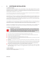
Discontinuous Interference Analyzer DIA 1512 D User Manual Discontinuous Interference Analyzer DIA 1512 D User Manual Contens 1. 1.1. 1.2. 1.3. 1.4. 1.5. 1.6. 1.7. 2. 2.1. 2.2. 2.3. 2.4. 2.5. 2.6. 3. 3.1. 3.2. 3.3. 4. 4.1. 4.2. 4.3. 4.4. 4.5. 4.6. 4.7. 4.8. 4.9. 4.10. 4.10.1. 4.10.2. 5. 5.1. 5.2. 5.3. 5.4. 5.5. 6. 6.1. 6.2. 6.3. 6.4. 6.5. 6.6. 6.7. 6.8. 6.9. 7. 7.1. 8. Safety advice......................................................................................................................... 5 General....................................................................................................................................................... 5 Connection to the mains and PE.............................................................................................................. 5 Risk of electric shock................................................................................................................................. 5 Operating Environment............................................................................................................................. 5 Test execution........................................................................................................................................... 5 Dangers concerning the EUT.................................................................................................................... 6 Applicable safety standards...................................................................................................................... 6 Storage, transport, unpacking and delivery information.................................................... 7 General....................................................................................................................................................... 7 Storage and transport............................................................................................................................... 7 Unpacking.................................................................................................................................................. 7 Model range and options.......................................................................................................................... 7 DIA 1512D scope of delivery..................................................................................................................... 8 DIA 1530A scope of delivery..................................................................................................................... 8 Introduction........................................................................................................................... 9 Operating elements of the front panel .................................................................................................... 9 Operating elements of the back plane................................................................................................... 10 Three-Phase Adapter DIA 1530A............................................................................................................ 11 Hardware Installation.......................................................................................................... 12 Switching on............................................................................................................................................ 14 Connecting the Splitter............................................................................................................................ 14 Switching Operations.............................................................................................................................. 14 Source Connection.................................................................................................................................. 14 Calibration................................................................................................................................................ 14 Calibration Source................................................................................................................................... 14 Using a Spectrum Analyzer as an External Receiver............................................................................. 14 External Test Receiver Example – R&S ESS ........................................................................................... 15 Setup for measurement discontinuous disturbance voltages.............................................................. 16 Three-Phase Adapter DIA 1530A............................................................................................................ 17 Installation................................................................................................................................................ 17 Operation................................................................................................................................................. 17 Software Installation........................................................................................................... 18 Software versions.................................................................................................................................... 18 Getting started with the software........................................................................................................... 18 New command........................................................................................................................................ 18 Open command . .................................................................................................................................... 19 DIA Control Panel.................................................................................................................................... 19 File Menu Commands.......................................................................................................... 20 File Menu................................................................................................................................................. 20 New command........................................................................................................................................ 20 Open command....................................................................................................................................... 20 Close command ..................................................................................................................................... 20 Save command........................................................................................................................................ 20 Save As command................................................................................................................................... 20 Print command........................................................................................................................................ 20 Print Preview command.......................................................................................................................... 21 Exit command . ....................................................................................................................................... 21 Edit Menu Commands......................................................................................................... 21 Edit Menu................................................................................................................................................. 21 View Menu Commands....................................................................................................... 22 347-480 E01 3 4 8.1. 8.2. 8.3. 8.4. 9. 9.1. 9.2. 9.3. 9.3.1. 9.3.2. 9.4. 9.5. 10. 10.1. 10.2. 10.3. 10.4. 10.5. 11. 11.1. 11.2. 11.3. 12. 12.1. 12.2. 13. 13.1. 13.2. 14. View Menu............................................................................................................................................... 22 Toolbar command................................................................................................................................... 22 Status Bar command............................................................................................................................... 22 View Timings command.......................................................................................................................... 23 Test Menu commands......................................................................................................... 25 Test Menu................................................................................................................................................ 25 DIA Control Panel ................................................................................................................................... 25 Run Settings ............................................................................................................................................ 25 RunA Limits dialog................................................................................................................................... 26 Run B Limits dialog.................................................................................................................................. 26 Click Times............................................................................................................................................... 27 Reset ....................................................................................................................................................... 27 Window Menu Commands.................................................................................................. 28 Window Menu.......................................................................................................................................... 28 New command ....................................................................................................................................... 28 Cascade command ................................................................................................................................ 28 Tile command.......................................................................................................................................... 28 1, 2, ... command . .................................................................................................................................. 28 Help Menu............................................................................................................................ 28 Help Menu................................................................................................................................................ 28 Help Topics.............................................................................................................................................. 28 About command...................................................................................................................................... 28 Technical specifications...................................................................................................... 29 DIA 1512D................................................................................................................................................ 29 Three-Phase Adapter DIA 1530A............................................................................................................ 29 Maintenance........................................................................................................................ 30 General..................................................................................................................................................... 30 Cleaning................................................................................................................................................... 30 Disposal................................................................................................................................ 30 DIA 1512D 1. Safety advice The generator and its accessories operate at mains voltage. These operating instructions form an integral part of the equipment and must be available to the operating personnel at all times. All the safety instructions and advice notes are to be observed. Neither Teseq GmbH nor any of its subsidiary sales organizations can accept any responsibility for personal, material or consequential injury, loss or damage that results from improper use of the equipment and accessories. WARNING: Improper or careless handling can be fatal! Use of the DIA 1512D is restricted to authorized and trained specialists 1.1. General Use of the DIA 1512D is restricted to authorized and trained personnel only. The DIA 1512D is to be used only for the purposes indicated by the manufacturer.. 1.2.Connection to the mains and PE The instrument conforms to protection class 1. Operation without a protective earth connection is forbidden! Handle the power cord carefully. Never use the product if the power cable is damaged. 1.3.Risk of electric shock To reduce the risk of electric shock, do not remove parts from the housing. There are no user serviceable parts inside the unit. Certain parts inside the instrument work at mains voltage and are not provided with any protection against being touched. Only approved accessory items, connectors, adapters, etc. are to be used to ensure safe operation. 1.4.Operating Environment Operate the equipment only in dry surroundings. Allow any condensation that occurs to evaporate before putting the instrument into operation. Do not exceed the permissible ambient temperature, humidity or altitude. Do not insert foreign objects in the holes of the unit. Do not place the product on radiators or fan heaters. The ambient temperature must not exceed the maximum specified temperature of this product. 1.5.Test execution The test area must be organized that no unauthorized persons have access during execution of a test. Operating the product requires special training and intense concentration. Make certain that persons who use the products are physically, mentally and emotionally fit enough to operate the products; otherwise injuries or material damage may occur. EUTs together with all accessories and cables are to be regarded as being live during the execution of a test. The safety instructions concerning all the instruments and associated equipment involved in the test setup are to be observed. The configuration of the test setup is to be strictly in compliance with the methods described in the relevant standard to ensure that the test is executed in a compliant manner. 347-480 E01 5 6 1.6.Dangers concerning the EUT EUTs are frequently simply functional samples that have not previously been subjected to any safety tests. Therefore in some cases, the EUT is quickly damaged through internal overloads caused by the control electronics being disrupted. The EUT may even begin to burn. As soon as the EUT shows signs of damage the test should be stopped and the equipment under test should be switched off. Possible erroneous behavior by the EUT for example, a robotic device may misbehave, or a temperature regulator may fail. 1.7. Applicable safety standards Development and manufacture of the instrument complies with ISO 9001. The equipment conforms with the essential requirements of the EMC Directive 2004/108/EC and Low Voltage Directive (LVD) 2006/95/EC. DIA 1512D 2. Storage, transport, unpacking and delivery information 2.1.General Save all packing materials! They will be needed in order to safely package the equipment for calibration service or repair. Packaging materials Carton: Cardboard Padding: CFC-free polystyrene foam Plastic bags: Polyethylene Avoid risk of condensation! If a large temperature differential has occurred, allow time for the temperature to stabilize. This may take several hours. 2.2.Storage and transport Do not stack, either packed or unpacked. Do not stand on end; arrows on the packaging must always point upwards. Protect from dampness, heat, cold and rain Do not throw Do not sit or stand on the instrument and packaging. 2.3.Unpacking Is the packaging damaged? If YES Are all the packages present and correct? If NO Open the packaging, remove the accessories. Grip the instrument at the sides and lift it from the packaging. Are the instrument or accessories damaged? If YES Are the contents of the package complete? If NO Keep the instruction manual with the instrument. Keep the packaging. ☎ ☎ transportation company transportation company ☎ ☎ transportation company Teseq sales office 2.4.Model range and options Part number Description 347-480 347-500 97-347-480 DIA 1512D Discontinuous Interference Analyzer (DIA), included 150 kHz, 500 kHz, 1.4 MHz and 30 MHz receivers DIA 1530A Option for DIA 1512D, 3-phase contractor and current sensor DIA 1512-TC Traceable calibration (ISO17025), order only with DIA 1512D 347-480 E01 7 8 2.5.DIA 1512D scope of delivery DIA 1512D mainframe including splitter, Quasi peak receiver “Plug-In“ modules with fixed frequencies at 150 kHz, 500 kHz, 1.4 MHz and 30 MHz. Operating manual IL 1948 Splitter Lead IL 1949 Splitter Internal Receiver Lead (4x) IL 2178 IF lead 530017 Power Socket 530019 Power Plug 720033 Fuse A1 720034 Fuse 2A (2x) DIS 9966 Click software on CD Power Lead UK 580000 Power Lead USA/Japan 580001 (no PSE mark) Power Lead Europe 580003 If any signs of damage are found, no attempt should be made to install the instrument, which should be returned to Teseq GmbH or the local agent. If the shipping carton has been damaged, retain the shipping carton and packing material for the carrier’s inspection. Check that the equipment is complete as in the packing list above. 2.6.DIA 1530A scope of 3 Phase Adapter DC Lead Assembly Cable Assembly 32A CEE17 Plug 32A CEE17 Socket delivery DIA1530A CHA9549 IL6004 If any signs of damage are found, no attempt should be made to install the instrument, which should be returned to Teseq GmbH or the local agent. If the shipping carton has been damaged, retain the shipping carton and packing material for the carrier’s inspection. Check that the equipment is complete as in the packing list above. DIA 1512D 3. Introduction 9 The DIA 1512D is a multi-channel discontinuous interference analyzer conforming to the requirements of CISPR 16-1-1 and CISPR 14-1. The analyzer can have up to six independent channels for performing interference analysis, (counting clicks), at different frequencies. The standard version includes Quasi peak receiver “Plug-In“ modules with fixed frequencies at 150 kHz, 500 kHz, 1.4 MHz and 30 MHz. Using the DIA 1512D with more than one receiver is similar to the use of a single channel analyzer. Instead of one set of accumulated click totals, there are several. After an appliance has been tested the click totals on each line may be examined independently to see whether the appliance has passed or failed at the corresponding frequency. Some test results are common to all channels, such as observation time and number of switching operations. The operating software DIS 9966 is used to set up and run tests. Analysis of the results is performed and reports can be printed. The DIS 9966 should be installed on a PC with Windows 98 or higher operating system. 3.1. Operating elements of the front panel RF Splitter input, connection to LISN/ AMN Receiver module RF input, connection to RF Splitter outputs Pulse waveform outputs, DC coupled detector output RF Splitter outputs, connection to receiver module RF input or/ and external receiver Figure 1: Front view of DIA 1512D 347-480 E01 Remote interface, RS232, connection to PC Audio outputs, 3.5 mm, connection to headphones LED, Switched to green if operates 10 3.2.Operating elements of the back plane CW 10 MHz and 30 MHz reference output CW Level control and ON/ OFF switch EUT mains supply, connection to the EUT Switch for selecting the current sensor EUT mains supply, input, connection to the mains PE N Figure 2: Back view of DIA 1512D DIA 1512D PE L External current sensor (DIR 1530A) L N Mains switch Fuse Switch for setting the threshold of the internal sensor DIA mains supply Voltage selector 3.3.Three-Phase Adapter DIA 1530A When used with a DIA1512D (or suitably modified DIA1512C) the DIA1530A allows the measurement of discontinuous disturbances of equipment having a three-phase power supply requirement. Equipment having a maximum continuous operating current of 30 A can be tested. The DIA1530A has a selectable current threshold for detecting switching operations of the EUT. Any of the three phases can be selected for the detection of switching operations. EUT mains supply, connection to the mains Voltage selector (Must be set to same as DIA 1512D Contactor control input, connection to DIA 1512D Earth connector Figure 3: Operating elements and connectors of DIA 1530A 347-480 E01 Select phase Current sensor output Switching operations threshold EUT mains supply, connection to the EUT (not shown) 11 12 4. Hardware Installation Caution: The DIA 1512D is supplied set for 230/240V operation. The voltage selector on the rear panel must be changed for 100/110/115 Volt operation. The DIA 1512D must be installed on a level surface and wired to a power outlet with a protective earth pin. The power inlet is a standard IEC three-pin socket. The plug-in modules must be pushed fully into the main frame and the retaining screws tightened to ensure proper earth connection. Refer to the connection diagrams for instructions on wiring the appliance power line through the DIA 1512D. The following tables show the internal receiver settings for DIP switches 1 to 7. Switch 8 is not used. S1-S4 should not be changed; they are read by the software to know the internal receiver frequency. (They do not change the receiver frequency.) Receiver Frequency: S1 S2 S3 S4 150 kHz* 1 0 0 0 160 kHz 0 0 1 1 455 kHz 1 1 1 0 500 kHz* 0 1 0 0 550 kHz 1 0 1 1 1 MHz 0 1 1 1 1.4 MHz* 1 1 0 0 3.5 MHz 1 1 1 1 10 MHz 0 0 0 1 10.7 MHz 0 0 1 0 21.4 MHz 1 0 1 0 30 MHz* 0 1 1 0 *) Part of the regular scope of delivery. Table 1: Internal receiver settings for DIP switches 1 to 4. . DIA 1512D S5-S7 tell the software the position of the receiver in the main unit (1 to 6, left to right). 13 Receiver Position S5 S6 S7 1 (left) 0 0 0 2 0 1 1 3 1 1 0 4 1 0 0 5 0 1 1 6 (right) 1 1 1 Table 2: Position of the receiver in the main unit, general Receivers are supplied set to the following default S5 to S7 position settings. These are not all different, (there are more than 6 frequencies available) so it will be necessary to change the setting on a receiver if you use it at the same time as another receiver with the same settings of S5 to S7. The DIA 1512D will not operate correctly if two receivers are set to the same position code. Receiver Frequency: Default Position S5 S6 S7 150 kHz 1 0 0 0 160 kHz 6 1 0 1 455 kHz 5 0 0 1 500 kHz 2 1 0 0 550 kHz 6 1 0 1 1 MHz 6 1 0 1 1.4 MHz 3 0 1 0 3.5 MHz 6 1 0 1 10 MHz 6 1 0 1 10.7 MHz 5 0 0 1 21.4 MHz 5 0 0 1 30 MHz 4 1 1 0 Table 3: Position of the receiver in the main unit, default position 347-480 E01 14 4.1.Switching on The power switch is located on the rear panel. The DIA 1512D must be on before starting the operating software program. 4.2.Connecting the Splitter When performing a single channel interference measurement the single receiver is connected to an Artificial Mains Network (AMN), also known as a Line Impedance Stabilization Network (LISN) which isolates the appliance under test from the mains supply. In a multiple channel test all of the receivers must be connected to the same mains network. This means that the signal splitter must be used. This is located on the front panel at the extreme left of the unit. The splitter has one input, which should connect to the RF signal from the mains network, and 8 outputs. These connect one to each receiver to be used. Unused outputs may be left unconnected. If the splitter is used its attenuation must be compensated for by reducing the receiver attenuation by 25 dB. 4.3.Switching Operations A switching operation is defined as a change in the EUT supply current above or below the threshold. This can be set to be 10 mA or 200 mA. A switch on the rear of the unit sets the level. The higher current position allows devices to be tested that have high continuous supply currents. 4.4.Source Connection This RF signal from the LISN is connected to the RF input socket on the front of the receiver, using an SMB connector. Alternatively, when several receivers are to be used, the source may be connected to the input of the splitter on the left-hand side of the DIA 1512D, and several short SMB terminated cables used to connect the splitter to each of the internal (or external) receivers. 4.5.Calibration The software can calibrate all the internal receivers fitted to the DIA 1512D simultaneously. The sensitivities of the internal receivers are adjusted, using internal reference calibration sources, such that after calibration the sensitivities are correct to within ±1 dB. 4.6.Calibration Source The 10 MHz calibration source on the back panel of the DIA 1512D should be switched off when it is not being used to set up external receivers. This is to avoid the possibility of interference with either the internal or external receivers. 4.7.Using a Spectrum Analyzer as an External Receiver The optional supplied receiver modules with 455 kHz, 10.7 MHz and 21.4 MHz are designed to interface to the intermediate frequency (IF) output of a spectrum analyzer (or measuring receiver). Each unit contains the 9 kHz bandwidth filter, quasi-peak detector with appropriate time constants and threshold detector. The analyzer can be tuned to any frequency of interest in the range 150 kHz to 30 MHz but must be in zero frequency span mode to make measurements. The following calibration procedure will ensure that the threshold in the receiver modules is set to a known level at the input of the spectrum analyzer. Connect the 10.7 MHz (21.4 MHz) output from the spectrum analyzer to the receiver module input. Connect the 10 MHz output from the rear of the DIA 1512D to the spectrum analyzer RF input, and turn the output on. Set the reference level at about 40 dB above the required test level. (This is to avoid signals 40 dB above DIA 1512D the threshold overloading the analyzer). Typically this will be 0 dBm. Set the analyzer resolution bandwidth to about 10 kHz, select zero span and tune the analyzer to the 10 MHz signal from the DIA 1512D. (The DIA receiver modules have a bandwidth of 9 kHz so it is important to tune the analyzer precisely). Adjust the output from the DIA 1512D to a convenient level on the analyzer e.g. -30 dBm. Select the specific receiver module on the DIA 1512D. Adjust the attenuator on the specific receiver module to get the signal as close as possible to 0 dB on the DIA 1512D display. Press Cal on the DIA 1512D. Adjust the attenuator on the specific receiver module to get the desired threshold level. For example, of the calibration was at -30 dBm and a threshold of -40 dBm is needed, add 10 dB to the attenuator (0 dBm=107 dBμV). Increase the resolution bandwidth of the analyzer to 100 kHz (or the nearest available value on the analyzer), tune it to the required frequency and connect the LISN output to be measured to the RF input. (The bandwidth of the analyzer must be widened to ensure that the 9 kHz filter in the specific receiver module is the narrowest filter in the signal path). When the software program in running, by clicking on the receiver number (1 to 6) in the display, you can enter the real frequency of the external receiver, to appear on the display and in test reports. 4.8.External Test Receiver Example – R&S ESS The following procedure should be followed as closely as possible for other measuring receivers. Connect the 10.7 MHz IF out on the ESS to the 10.7 MHz receiver module in the DIA 1512D. Teseq can supply a suitable cable, part no. IL2178 for this purpose. Setting Up Switch Auto Attenuation OFF on ESS receiver. Select average (AV) detector on ESS. Set ESS attenuator to 80 dB. Inject 10 MHz calibration source from DIA 1512D rear panel to ESS input. Set ESS tuning to fine control and tune the receiver for maximum calibration signal level. Adjust calibration source for a reading of 80 dBµV on ESS. Check again that the tuning is maximized. Adjust DIA 1512D calibration source level for 0dB on ESS meter. Press CAL on the DIA 1512D. Adjust DIA 1512D attenuator to indicate 0dB on DIA 1512D display (typically 35 dB of attenuation is needed), there may be up to ½ dB setting error as the attenuator can is adjusted in 1 dB steps. Setting the Measurement Limit Select the Quasi-Peak (QP) detector on the ESS. It is important to select the QP detector, so that the correct conditions (measurement bandwidth, internal gain/attenuation) of the receiver are set. (This allows correct operation of the ESS, but the QP detector used for click measurements is in the DIA 1512 receiver). Example 1: Limit 60 dBµV: - set-up as above and adjust ESS receiver attenuation to 60 dB. Example 2: Limit 66 dBµV: - set-up as above and adjust ESS receiver attenuation to 60 dB and increase attenuation on DIA 1512D by 6 dB. When the software program in running, by clicking on the receiver number (1 to 6) in the display, you can enter the real frequency of the external receiver, to appear on the display and in test reports. 347-480 E01 15 16 4.9.Setup for measurement discontinuous disturbance voltages Artificial Mains Network Equipment under test Mains Out In Mains port RF Out Click analyzer PC Out RF In In EUT Mains supply Mains RS232 remote Mains Figure 4: Setup for single-phase EUT Artificial Mains Network Equipment under test Mains Out In Mains port, 3 ph. RF Out 3 phase adapter Out In Out Click analyzer Contactor control Current sense In EUT Mains supply, 3 ph. Figure 5: Setup for three-phase EUT DIA 1512D PC Out In RF In In EUT Mains supply Mains RS232 remote Mains 4.10. Three-Phase Adapter DIA 1530A Caution: The DIA 1530A voltage selector must be set to the single-phase voltage supplied to the Contactor In socket on the DIA 1512. The DIA 1530A does not contain fuses, as the unit can be used with many different types of EUT. Ensure that the EUT and/or the power installation provide adequate safety fuses. The maximum allowable continuous current is 30 A and the peak current is 200 A. There are no user serviceable parts in the DIA1530A. Live parts are exposed if the cover is removed. 4.10.1. Installation The DIA 1530A should be installed on a level surface and connected to a three-phase power installation via a suitable Artificial Mains Network (AMN); sometimes called by the more generic name Line Impedance Stabilisation Network (LISN). Refer to the relevant standards for the product being tested for guidance. The unit must be connected to a good ground point. The power inlet is a standard IEC socket. Connect ‘Contactor Control’ socket on DIA 1530A to ‘Contactor Out ‘ on rear of DIA 1512 using cable supplied. Connect ‘Current Sensor Output’ socket on DIA 1530A to ‘External Current Sensor Input’ on rear of DIA 1512 using cable supplied. Connect earth post on DIA 1530A to a good ground. Connect EUT (Equipment Under Test) to the ‘Output’ socket of DIA 1530A – see front of unit for pin connections. Ensure supply is off, and then connect to ‘Input’ socket of DIA 1530A – see front of unit for pin connections. 4.10.2. Operation Set ‘Current Sensor’ switch on rear of DIA 1512 to External. Switch on DIA 1512 and power for EUT. Set the ‘Current Threshold’ control to 0.1 A, 1.0 A or 10 A, as required. Select phase required. Follow normal DIA 1512 procedure. It may be necessary to change the Current Threshold control to detect switching operations, if required. 347-480 E01 17 18 5. Software Installation 5.1. Software versions DIS9966 v2.50 is identical to DIS9966 v1.40 in most respects. The only major change has been to convert the software from the 16 bit version (v1.40) to the 32 bit version (v2.50) so that DIS9966 can run correctly on Windows 98, 2000 and XP platforms. For identification purposes, the icons visible in the top left corner of the DIS9966 window are different for v1.40 and v2.50. If this software is supplied with a new DIA1512 and, therefore, DIS9966 v1.40 (or earlier) was not installed on the PC, the following notes are irrelevant and can be ignored. If this software is installed as an update to an existing installation, whether on the same computer or on a different computer, it is vitally important that the original DIAP1.PAR and DIAP2.FRQ files are copied from the v1.40 installation folder to the v2.50 installation folder. By default, the v1.40 installation DIAP files will be in C:\ DIS9966 and the v2.50 DIAP files are in C:\Program files\DIS9966. Failure to do so may cause erroneous data to be recorded in subsequent tests using v2.50. This installation will not copy existing user data to the new installation folder so you will need to copy all previous data from the v1.40 data location (usually the installation folder, by default C:\DIS9966) to the v2.50 data location (by default C:\Program files\DIS9966) unless you use a separate user data location. DIS9966 v1.40 and DIS9966 v2.50 can co-exist on the same PC in different folders. You may, therefore, wish to retain the v1.40 installation and it’s data until you have installed v2.50 and verified correct operation. 5.2.Getting started with the software IMPORTANT. This section only provides basic information, and is not updated as the software changes. Your main information about the current version of the program is provided in the Help in the DIS 9966 program. This is also context sensitive, so you can press this F1 key at any time for help on the current operation. You must first have a result output document open (see File Menu: New or Open). Then open the Control Panel (see Test Menu: Control Panel) to establish a connection with the DIA. The EUT must be connected to the DIA. The DIA must be switched on and calibrated before it is first used. The first test run (RunA) will be at Continuous Interference thresholds which can be set on the Control Panel, and will establish the Click Rate. To start the run, press Run on the Control Panel to bring up the RunA limits dialog box, and then press Start Run. To start RunB when RunA is complete, press Run on the Control Panel, then RunB on the RunA limits dialog box to bring up the RunB limits dialog. The Click Rate is then used by the program to calculate Discontinuous Interference thresholds for RunB. Check that the settings are correct, and then press Start Run. When RunB is complete results report can be viewed (View Menu: View Report). If detail timings are required, they can be retrieved from the DIA (Test Menu: Click times) and viewed (View Menu: View Timings); the display can be toggled between a graphic display and a listing (View Menu: View Report). 5.3.New command Use this command to create a new test results document. The apparatus details dialog will appear. DIA 1512D 5.4.Open command Use this command to open an existing document in a new window. You can open multiple documents at once. Use the Window menu to switch among the multiple open documents. See Window 1, 2, ... command. 1, 2, ... command (Window menu) A list of currently open document windows is displayed at the bottom of the Window menu. A check mark appears in front of the document name of the active window. Choose a document from this list to make its window active. 5.5.DIA Control Panel The Control Panel allows the DIA settings to be adjusted and displayed, and is used to start or end a test. Its title bar shows the name of the results output document that will record test output. If you wish to change to a different document, you must close the Control Panel, click on an Analyzer Totals window for the desired document, and then re-open the Control Panel. Individual boards each have a Board Control box. Below these is a display showing whether the next run will be <<RunA>>, <<RunB>> or a <<Free Run>>. Pushbuttons: Calibrate: This button must be pushed to make the DIA calibrate itself after it has been powered up; the calibration will be effective until it is powered down. During calibration, the display for each board will indicate that calibration is being carried out, and no action should be taken until this is completed. Run: This button brings up a run settings dialog which may be altered as necessary before commencing a test run. Default sensitivity settings listbox: This has a range of settings for certain types of apparatus under test. Clicking on this will reset the thresholds on all boards. Splitter Checkbox: This must be checked if and only if the splitter is used. An automatic offset to all boards to account for the splitter attenuation is set if this is checked. Board Control Boxes Board Control boxes are displayed in the Control Panel window for every board present. Board Control checkboxes: Active: This must be checked if the board is to be included in a test. Meter: This should be checked for the meter display to show the noise level on this board. Frequency setting: This can be changed either directly in the Edit box, or by using the slider control. Default settings for all boards may be set from the Control Panel Window for various different classes of equipment under test for RunA (i.e. at continuous emission threshold). The program will calculate frequencies for RunB (i.e. at discontinuous threshold); these may be altered in the <<RunB Limits dialog box>>. 347-480 E01 19 20 6. File Menu Commands 6.1. File Menu The File menu offers the following commands: Command Description New Creates a new document. Open Opens an existing document Close Closes an opened document. Save Saves an opened document using the same file name Save AS Saves an opened document to a specified file name. Print Prints a document. Print Preview Displays the document on the screen as it would appear printed. Print Setup Selects a printer and printer connection. Exit Exits this program. 6.2.New command Use this command to create a new test results document. The apparatus details dialog will appear. 6.3.Open command Use this command to open an existing document in a new window. You can open multiple documents at once. Use the Window menu to switch among the multiple open documents. See Window 1, 2, ... command. 6.4.Close command Use this command to close all windows containing the active document. You may want to save changes to your document before you close it. If you close a document without saving, you lose all changes made since the last time you saved it. Before closing a document with new results, the program will prompt you to save the changes. 6.5.Save command Use this command to save the active document to its current name and directory. 6.6.Save As command Use this command to save and name the active document. The program displays the Save As dialog box so you can name your document. To save a document with its existing name and directory, use the Save command. 6.7.Print command Use this command to print a document. DIA 1512D The report printed depends on which window is active (has a blue title bar) when the command is entered. If a Disturbance Timings Window is active, a detail disturbance timings report is produced for the board being shown in the window; otherwise the normal test results report is obtained. This command presents a Print dialog box, where you may specify the range of pages to be printed, the number of copies, the destination printer, and other printer setup options. 6.8.Print Preview command Use this command to display the active document as it would appear when printed. The report printed depends on which window is active (has a blue title bar) when the command is entered. If a Disturbance Timings Window is active, a detail disturbance timings report is produced for the board being shown in the window; otherwise the normal test results report is obtained. When you choose this command, the main window will be replaced with a print preview window in which one or two pages will be displayed in their printed format. The print preview toolbar offers you options to view either one or two pages at a time; move back and forth through the document; zoom in and out of pages; and initiate a print job. 6.9.Exit command Use this command to end your DIA session. 7. Edit Menu Commands 7.1. Edit Menu The edit menu offers the following commands: When a view timings window is active: Command Description Insert allows insertion of a disturbance after the current one Delete deletes the current disturbance Amend allows amendment of current disturbance timings When any other window is active: Command Description Amend allows amendment of apparatus details, etc, in current document via the apparatus details dialog Apparatus details dialog box Specify the details of the apparatus under test: these will appear on the results report This display appears when the file/new menu command is selected, or, for a file already existing, when the edit/amend menu command is selected. Changing the file ID will change the document name (the program will add the standard .drd file extension) 347-480 E01 21 22 8. View Menu Commands 8.1.View Menu The View menu offers the following commands: Command Description Toolbar shows or hides the toolbar. Status Bar shows or hides the status bar View Timings Graphic display of detail timings for selected board. View Report toggles displays to and from report formats. Amend gives results report based on your own format 8.2.Toolbar command Use this command to display and hide the Toolbar, which includes buttons for some of the most common commands in this program, such as File Open. A check mark appears next to the menu item when the Toolbar is displayed. See Toolbar for help on using the toolbar. Toolbar To hide or display the Toolbar, choose Toolbar from the View menu (ALT, V, T). Click To Open a new document. Open an existing document. The program displays the Open dialog box, in which you can locate and open the desired file. Save the active document or template with its current name. If you have not named the document, The program displays the Save As dialog box. Print the active document. Display version number of program. Switches to help cursor. You can then click on an item to get appropriate help. 8.3.Status Bar command Use this command to display and hide the Status Bar, which describes the action to be executed by the selected menu item or depressed toolbar button, and keyboard latch state. A check mark appears next to the menu item when the Status Bar is displayed. See Status Bar for help on using the status bar. Status Bar The status bar is displayed at the bottom of the application window. To display or hide the status bar, use the Status Bar command in the View menu. DIA 1512D The left area of the status bar describes actions of menu items as you use the arrow keys to navigate through menus. This area similarly shows messages that describe the actions of toolbar buttons as you depress them, before releasing them. If after viewing the description of the toolbar button command you wish not to execute the command, then release the mouse button while the pointer is off the toolbar button. The right areas of the status bar indicate which of the following keys are latched down: IndicatorDescription CAP The Caps Lock key is latched down NUM The Num Lock key is latched down SCRL The Scroll Lock key is latched down 8.4.View Timings command Use this command to open a window to display click details graphically. A prompt will first appear to select the board to be displayed. After a run, detail timings must be retrieved from the DIA before they are available for viewing- see Test Menu: Click Times). Once retrieved, detail timings for the latest run will be saved with other data on the results output document. See View Clicks Window for help on using it. Click Times (Test menu) Use this command after a run to retrieve detail click timings from the DIA. A dialog will appear in which you set the board number to be retrieved. After click timing details have been retrieved, they can be examined in a disturbance timings window (see View Menu: View Timings). View Clicks Window This Window allows the detail results from one DIA board to be inspected. A Timings Listing can be printed, and this window’s display can be toggled to show it (View Menu: View Report), but the main display is graphical. Disturbances are shown as equal height block outlines on a horizontal time line, the block width representing duration. Short clicks are in BLACK, long in GREEN, and continuous disturbance is in RED. Where disturbances are close enough for concatenation to apply, this is indicated by a line from the start of the first to the end of the last disturbance which rises higher than the raw disturbance block and is coloured according to the total concatenated time. In the top left corner, there are boxes where you can enter the number of the first displayed disturbance (numbering is chronological), and the scale of the display (in pixels per millisecond). There is a scale to size button which causes the whole run to be shown. Below the time line there is an arrow indicating a ‘current’ disturbance. The duration of the disturbance indicated by this arrow, its number, and the times from the prior and to the next disturbances are shown at the top of the display. Where there are more than 2 disturbances in 2 seconds, a thick pink line is drawn through them indicating a 2-second period (providing the disturbances are all on the display). 347-480 E01 23 24 Controlling the display: The display can be moved by entering a number for the first disturbance; using the scrollbar; using the left or right arrow keys; changing the scale (the time pointed to by the arrow remains unmoved); zooming to a part of the display by clicking the mouse right button on the block display, dragging it sideways to open up a zoombox, and then right-clicking inside that box. Setting the current position: The arrow representing this can be moved by using the left or right arrow keys to move to the beginning of the prior or next disturbance; clicking the mouse below the time line to move to the beginning of a disturbance; clicking the mouse anywhere on a disturbance to move to an intermediate time (the current disturbance is then the latest starting on or before the current time). The scale can be doubled/halved with the UP/DOWN arrow keys or PGUP/PGDOWN. DIA 1512D 9. Test Menu commands 9.1. Test Menu The Test menu offers the following commands: Command Description Control Panel Shows DIA Control Panel. Run Settings Displays Run Limits dialog box, which contains a button to start a test run. Click Times Allows retrieval of detail timings for individual boards from the DIA after a run Reset Resets DIA counts to zero. Other commands... Command Description Parameters Allows inspection of current DIA parameter . (including definitions of clicks). Do not edit these Timings Allows retrieval of amplitude timings (in the same way that Click Times are retrieved). The amplitude signal is used internally by the DIA in determining whether or not disturbance signals exceed the sensitivity set. You will not normally wish to see these. Usertest Allows direct sending of commands to DIA.You will not normally use this 9.2.DIA Control Panel Use this command to open a window to display the DIA Control Panel. The DIA will be attached to the document whose window is active (i.e. has a blue title bar) when this command is made. See Control Panel for help on using the control panel. If you have difficulty establishing communications with the DIA (perhaps by opening the Control Panel before switching the DIA power on), you should exit the program entirely before attempting to re-open the Control Panel- simply closing and re-opening the Control Panel window does NOT re-initialise communications. 9.3.Run Settings Use this command to display a Run Limits Dialog for either RunA or RunB. Each dialog contains a button to access the other. The Run Limits dialogs allow run settings to be adjusted and test runs to be started. They also each contain a toggle that permits a non-test run (freerun), in which thresholds may be altered during the run. See RunA Limits or RunB Limits for help on using Run Limits dialogs. 347-480 E01 25 26 9.3.1. RunA Limits dialog This appears when the start button on the Control Panel is pressed when Run A is shown. Edit boxes: Description Duration: This determines the maximum duration of the run if none of the other limits are reached Max Continuous The maximum permitted total duration of continuous disturbance (i.e. the sum of disturbances that do not qualify as clicks). Max Clicks The maximum permitted total number of disturbances that qualify as clicks Stop After Count “radio buttons”: These determine whether the maximum click test will be applied to all or any board in the test, or to the switching operations count. If the latter is selected, then RunB threshold settings will also be based on the switching operations count. Pushbuttons Description Default Limits: This resets the preceding controls to the usual default settings. Free Run This is a toggle control. A freerun has no limits; this is indicated by shading out the edit boxes. Run Starts a run (either RunA or a freerun) and returns to the Control Panel Cancel Close the dialog without saving the setting RunB Limits: Opens the RunB Limits dialog box. Use this when RunA has been satisfactorily completed See also RunB Limits dialog. 9.3.2. Run B Limits dialog This appears when the start button on the Control Panel is pressed when Run B is shown. Edit boxes (for each board): Click Rate used: This is set to the rate obtained in Run A, either for the board concerned, or (if a different frequency has been set to be used by that board for click rate in the frequency parameter file) for the appropriate base frequency; or, if Run A was limited by a switching operations count, it is set to that count. If you change a click rate, the threshold will be recalculated. Click Threshold: The sensitivity setting for Run B. Click Limit: The maximum permitted total number of disturbances that qualify as clicks. DIA 1512D Click Rate “radio buttons”: These determine whether the threshold calculation uses the actual click rates from Run A, or the Switching Operations count from Run A (multiplied by a factor). In the latter case, you must make sure that the correct factor for the class of apparatus under test is entered here. If you click one of these buttons, the click rates and thresholds will be recalculated, overriding any prior manual alterations. Pushbuttons: Description RunA Limits Opens the RunA Limits dialog box. Use this if you want to start Run A again. Run Starts a run (either RunB or a freerun) and returns to the Control Panel. Cancel Closes the dialog without saving the settings Free Run This is a toggle control. A freerun has no limits; this is indicated by shading out the edit boxes. See also RunA Limits dialog. 9.4.Click Times Use this command after a run to retrieve detail click timings from the DIA. A dialog will appear in which you set the board number to be retrieved. After click timing details have been retrieved, they can be examined in a disturbance timings window (see View Menu: View Timings). 9.5.Reset This command will reset the DIA counts to zero before a freerun. For RunA or RunB (i.e. test runs), the counts are reset automatically. 347-480 E01 27 28 10. Window Menu Commands 10.1. Window Menu The Window menu offers the following commands, which enable you to arrange multiple views of multiple documents in the application window: Command Description New Window Creates a new window that views the same document Cascade Arranges windows in an overlapped fashion. Tilel Arranges windows in non-overlapped tiles Window 1,2 Goes to specified window. 10.2. New command Use this command to open a new results window for the active document. When you open a new window, it becomes the active window and is displayed on top of all other open windows. 10.3. Cascade command Use this command to arrange multiple opened windows in an overlapped fashion. 10.4. Tile command Use this command to arrange multiple opened windows in a non-overlapped fashion. 10.5. 1, 2, ... command A list of currently open document windows is displayed at the bottom of the Window menu. A check mark appears in front of the document name of the active window. Choose a document from this list to make its window active. 11. Help Menu 11.1. Help Menu The Help menu offers the following commands, which provide you assistance with this application: Command Description Help Topics Offers you an index to topics on which you can get help About Displays the version number of this application 11.2. Help Topics Use this command to display the opening screen of Help. From the opening screen, you can jump to instructions for using this program and various types of reference information. Once you open Help, you can click the Contents button whenever you want to return to the opening screen. 11.3. About command Use this command to display the copyright notice and version number of this program. DIA 1512D 12. Technical specifications 12.1. DIA 1512D Sensitivity: Attenuation: Pulse response, bandwidths etc.: Measurement frequencies: Frequency accuracy: Information displayed: Test duration: Construction: Power requirements: Size (l x W x H, including connectors): Weight: Operating temperature range: Computer requirements: Windows compatibility: 12.2. 20 dBμV (45 dBμV at input of splitter) 0-79 dB variable in 1 dB steps As for CISPR 16 Band B 150 kHz, 500 kHz, 1.4 MHz and 30 MHz ±5% No. of short clicks / No. of long clicks / No. of seconds of continuous interference (resolution 0.1 s). Greater than 2 clicks in 2 s indication / Duration of test (in units of 0.1 minute) / No. of switching operations, meter Indication 0 - 120 minutes in minute steps or continuous Programme controls a heavy duty contactor (15 amp) Manual control of contactor is also possible Eurocard frame mounted in standard instrument case with integral power supply 120 / 240 V, ±10%, 50 Hz AC, 100 Watt 470 x 280 x 290 mm 10 kg 10 to 30°C 200 MHz Pentium or compatible processor Mouse or compatible pointing device 32 MB RAM / 10MB Free Hard Disk space Serial port, must be free for connecting to DIA 1512D 98, 2000, XP, Vista, 7 Three-Phase Adapter DIA 1530A Maximum EUT continuous current: Peak EUT current (at switch on): Power Input connector: Power Output connector: Contactor Control: Switching Operations Current Threshold: Size (including power connectors and switches): Weight: Operating temperature range: 347-480 E01 30 A 200 A IEC 60309-2 Plug, 32A – 6h, 3P+N+ PE, 240/415V maximum IEC 60309-2 Socket, 32A – 6h, 3P+N+ PE, 240/415V maximum Selectable 100 -120 or 220 -240 VAC Selectable 0.1 A, 1.0 A or 10 A 520 x 270 x 200 mm 8 kg 0 to 40°C 29 30 13. Maintenance 13.1. General The DIA 1512D including the accessories need no special maintenance. The maintenance is limited to the cleaning of the contacts. The life time of the connectors is limited because of the contact durability. Teseq can replace the worn out connectors. No modifications are to be carried out on the DIA 1512D and accessories by the user. The mains fuse is 1A ANTI-SURGE HBC. 13.2. Cleaning The cleaning shall be done with dry cloth. If a wed cleaning would become necessary, make sure that no humidity will enter inside of the unit and clean the instrument housing with a damp cloth using a little mild, non-abrasive household cleanser if necessary. Chemicals must not be used for cleaning purposes 14. Disposal The unit is constructed that it can be dismantled right down to the component level. DIA 1512D Headquarters Teseq AG 4542 Luterbach, Switzerland T + 41 32 681 40 40 F + 41 32 681 40 48 sales @ teseq.com www.teseq.com Manufacturer Teseq GmbH 12623 Berlin, Germany Landsberger Str. 255 T + 49 30 5659 8835 F + 49 30 5659 8834 desales @ teseq.com China Teseq Company Limited T + 86 10 8460 8080 F + 86 10 8460 8078 chinasales @ teseq.com France Teseq Sarl T + 33 1 39 47 42 21 F + 33 1 39 47 40 92 francesales @ teseq.com Germany Teseq GmbH T + 49 30 5659 8835 F + 49 30 5659 8834 desales @ teseq.com Japan Teseq K.K. T + 81 3 5725 9460 F + 81 3 5725 9461 japansales @t eseq.com Singapore Teseq Pte Ltd. T + 65 6846 2488 F + 65 6841 4282 singaporesales @ teseq.com Switzerland Teseq AG T + 41 32 681 40 50 F + 41 32 681 40 48 sales @ teseq.com Taiwan Teseq Ltd. T +886 2 2917 8080 F + 886 2 2917 2626 uksales @ teseq.com UK Teseq Ltd. T + 44 845 074 0660 F + 44 845 074 0656 uksales @ teseq.com USA Teseq Inc. T + 1 732 417 0501 F + 1 732 417 0511 Toll free +1 888 417 0501 usasales @ teseq.com To find your local partner within Teseq’s global network, please go to www.teseq.com Teseq® is an ISO-registered company. Its products are designed and manufactured under the strict quality requirement of the ISO 9001. © May 2012 Teseq® Specifications subject to change without notice. All trademarks recognized. This document has been carefully checked. However, Teseq® does not assume any liability for errors or inaccuracies.