1
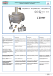
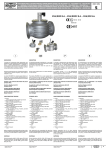
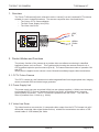
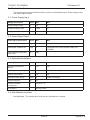
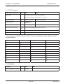
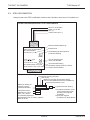
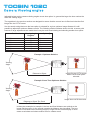
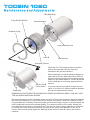
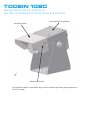
TOCSIN 102C CCTV CAMERA INSTALLATION AND USER INSTRUCTIONS OLIVER IGD Oliver IGD Limited 4a Pepper Road Stockport SK7 5BW England Tel: Fax: Email: Web Site: +44(0)161 483 1415 +44(0)161 484 2345 [email protected] www.oliver-igd.co.uk V7 TOCSIN T102 CAMERA T102 Manual 76 Contents CONTENTS 2 DOCUMENT STORAGE 3 1. OVERVIEW 4 2. PRODUCT MODES AND FUNCTIONS 4 2.1 CCTV Colour Camera 4 2.2 Power Supply Unit 4 2.3 Video Line Driver 4 3. PRODUCT INTERFACES 5 3.1 Power Supply Input 5 3.2 Video Signal Output 5 3.3 Mechanical Interfaces 5 3.4 Man-Machine Interface 5 4. PRODUCT ENVIRONMENT 6 4.1 Mechanical Requirements 6 4.2 Environmental Requirements 6 4.3 Electrical Power 6 4.4 Product Safety Requirements 6 5. PRODUCT ATTRIBUTES 7 5.1 CCTV Camera 5.2 Camera Lens (Field of View) note f3.6 lens as standard all other options contact product support.7 5.3 Reliability 7 5.4 Maintenance & Fault Finding 8 5.5 Training 8 7 15/06/10 Page 2 of 14 TOCSIN T102 CAMERA T102 Manual V7 1. Overview The Tocsin T102 camera [herein referred to as the ‘camera’] is a self contained CCTV camera suitable for use in industrial locations. The camera comprises three functional blocks: The Colour CCTV Camera Module The 24V Power Supply Unit (PSU) The Video Line Driver +24V S 0V l +Video Si l -Video S 2. Product Modes and Functions The primary function of the camera is to provide video surveillance monitoring in classified hazardous areas, such as Zone 1. This is achieved by housing the camera electronics in a ATEX certified explosion proof enclosure [Eex-d]. The camera has two modes of operation ON and OFF. When power is applied to the camera it turns ON and immediately begins video transmission. 2.1 CCTV Colour Camera The CCTV camera is a self contained unit with integrated fixed focal length optical lens, imaging sensor, automatic IRIS and video image generator. 2.2 Power Supply Unit The power supply converts a nominal 24Vdc into two voltage supplies (+/-9Vdc) used internally to energise the CCTV Colour Camera and Video Line Driver, all supplies have a common ground (GND) connection. The CCTV camera is powered from the +9Vdc . The video line driver is powered from +/-9Vdc (e.g. 18Vdc). 2.3 Video Line Driver The video line driver converts the 1V composite video output from the CCTV Camera into a 2V differential composite video signal (balanced line) suitable for transmission over either a 75R coaxial cable or 150R twisted pair cable. 15/06/10 Page 3 of 14 TOCSIN T102 CAMERA T102 Manual V7 3. Product Interfaces The camera has one signal interface with an option for differential output, Power Supply Input and Video Signal Output. 3.1 Power Supply Input Supply Specification Units Min Max Supply Voltage Range V 19 32 Absolute Voltage Limits V 18.50 36 Supply Power Consumption mW 70 1200 Video Signal Specification Units Min Max Coaxial Composite Signal Vpp 1 Composite into 75R Differential Twisted Pair Vpp 2 Composite into 150R (optional output P/N 5114902) Typical distance (PSU/cable dependant) M 500 3.2 Video Signal Output 3.3 Mechanical Interfaces Housing Specification Units Min Max Operating Temperature Range C -20 +55 Operating Humidity Range %RH 0 99 Non condensing Storage Temperature C -20 +70 Storage Humidity Range %RH 0 99 Non condensing Ingress Protection IP 67 Enclosure Surface Temperature C Ambient + 10 Connections See fig.1 below 3.4 Man-Machine Interface Not Applicable. The camera does not have any indications or controls. 15/06/10 Page 4 of 14 TOCSIN T102 CAMERA T102 Manual V7 4. Product Environment The camera has been ATEX certified for use in Zone 1 hazardous areas. 4.1 Mechanical Requirements The camera is mounted within the surveillance area. The M20 thread allows the camera to be mounted directly into a junction box for connection to suitable field cabling. A simple mechanical bracket can be used to mount the camera to a suitable structure. The camera should be oriented to obtain a clear and unobstructed view of the area. Ideally when mounted outside the camera will face away from the sun and other intense direct light sources, whilst this will not damage the sensor the cameras automatic exposure control will darken the video image to compensate. This results in less than optimal video picture quality. Care should be taken to site the camera in areas free from sources of mechanical vibration or where damage might result from on-going site operations. The camera should be mounted in such a way to minimise the likelihood of damage from sharp knocks or moving machinery/tools. 4.2 Environmental Requirements There are no special storage requirements. 4.3 Electrical Power The camera requires a 24V DC supply. 4.4 Product Safety Requirements Refer to ATEX certification. 15/06/10 Page 5 of 14 TOCSIN T102 CAMERA T102 Manual V7 5. Product Attributes 5.1 CCTV Camera Video Sensor Specification Units Min Max Sensor type -- Full Colour (PAL or NTSC sensor option) Sensor needs to be specified at time of order. Video Signal (EU) PAL 290 (H) x 320(V) 380 lines, 50 fields/sec Light Sensitivity Lux 0.5Lux @ F2 5600ºK -- Signal to Noise Ratio db 48 -- Lens Field of View (FOV) degre es Select fixed board type lens from 10 to 150 Focus Fixed Iris Automatic 5.2 Camera Lens (Field of View) note f3.6 lens as standard all other options contact product support. Lens (/ mm) 0 FOV( ) Recognition Distance (M) Depth of Vision (M) 1.9 150 2 4 2.5 130 3 6 2.9 92 3.5 8 3.6 78 4 10 4.3 57 6 12 6.0 38 8 16 8.0 26 12 24 12 15 16 32 16 10 30 60 5.3 Reliability Reliability Units Min Mean Time Between Failure Hrs 80,000 Max 15/06/10 Page 6 of 14 TOCSIN T102 CAMERA T102 Manual V7 5.4 Maintenance & Fault Finding Common Camera Faults Symptoms Cause Corrective Action No Video Picture No Power Connection Ensure that the power supply is connected properly No Video Signal Ensure that the video output connections are connected properly Video Signal Polarity Wrong Ensure the video cables are connected to the correct video signals from the camera Poor Video Cabling Ensure that the camera enclosure is connected to a clean earth Video Picture Corrupted (Noise) Ensure that the cable screen is connected to a clean earth at the one end only (generally the video equipment/monitor) Ensure that all electrical connections and terminals are properly made-off and tight Interference Ensure that the video signal cables are not run parallel to or mixed in with other high power/frequency signals Ensure that the video signal cabling does not run nearby any high power switching or transforming equipment Video Picture Blurred Video Picture Too Dark Camera Out Of Focus Return to the manufacturer Camera Optics Fouled Clean with a suitable optical glass cleaner or using a weak solution of detergent and water Low Light Level In dark or low light areas the video picture quality will reduce and the picture will become dark – consider installing conventional or Near-IR light sources 5.5 Training Installers and operators should be familiar with all regulation and codes of practice applicable to the site. 15/06/10 Page 7 of 14 TOCSIN T102 CAMERA T102 Manual V7 5.6 ATEX INFORMATION Always ensure the ATEX certification matches the hazardous area zone of intended use. TOCSIN 102 Hazardous Area CCTV Camera Module Red V in 18-32 VDC Black V in 0V DC Pink (-) Yellow Video Out (+) Observe Marked Warnings DO NOT OPEN WHEN AN EXPLOSIVE ATMOSPHERE MAY BE PRESENT. OLIVER IGD Ltd Manufacturer ATEX Markings with Explosive Protection Marking II 2 GD -20 C < Ta < +55 C Ex d IIC T6 Gb Ex tb IIIC T6 Db IP66 EU 'CE' Marking and ATEX Lab Number xxxx Sira 06ATEX1366X Rating 2W Serial Number T102C-xxxxx-2002 Environmental Rating Test Body Report Number & Power Device Serial Number Explanation of Markings Flameproof Housing Concept Gas Group Maximum Housing Temperature Taking Into Account Maximum Ambient Temperature Equipment Protection Level Maximum Rating Of EEx d IIC T6 Gb Internal Circuitry Rating 4W Max Certificate Number Sira 02ATEX1271X Conductive Dusts IIIC Suitable For Use In II 2 GD Zone 1 & 2 Areas In Potentially Explosive Atmospheres Due To Gases, Vapours Mists or Dusts. 15/06/10 IP66 Ingress Protection Rating 6-Complete Protection From Live Components Inside Housing, Dust Ingress Protection 6-Protection Against Conditions On Ships Decks Page 8 of 14 TOCSIN 102C Appendix 1. Accessories, Adjustments. TOCSIN 102C Hazardous Area Cameras & Accessories Camera Part Number Lens Option (f) 5121901 5114901 5122001 5122101 5122201 5122301 5122401 2.9mm 3.6mm 4.3mm 6.0mm 8.0mm 12.0mm 16.0mm Accessory Part Number Universal Mounting Bracket Junction Box Anti-Glare Shield Air Blow Adapter 5078701 5045801 5126001 5127001 Camera Lens Selection The standard camera lens option is 3.6mm and will cover the majority of applications. It is advisable for a new application to check that the standard 3.6mm lens option is correct. Normally with a fixed format camera there will be a specific item or area that is under surveillance. The lens option is calculated from having a rough idea of the height or width of this object and its proposed distance from the camera. The following formulas can then be applied for selection. It must be remembered that with any camera there is only a certain resolution available when viewed on the monitor. It is therefore important that the area of importance to be viewed makes maximum use of that resolution. The lens options listed can also be factory set for a particular ‘best picture’ distance for a given depth of field. Applications should be referred to Oliver IGD Ltd for advice on selection for best performance. For Known Object Height f = 2.4 x Distance to Object / Height of Object Camera is to be mounted 8M from an object 2.2M high f = 2.4 x 8 / 2.2 = 8.7 Nearest Lens Option P/N 5122201 (f8.0) For Known Object Width f = 3.4 x Distance to Object / Width of Object Camera is to be mounted 7M from an object 6.5M wide f = 3.4 x 7 / 6.5 = 3.7 Nearest Lens Option P/N 5114901 (f3.6) TOCSIN 102C Camera Viewing angles Indicated below are the camera viewing angles verses lens option. In general the larger the lens number the wider the viewing angle. The equations in the previous section are designed to ensure that the correct lens is fitted such that the final image fills the CCTV screen. It is also worth noting that once the lens option is selected for a given optimum image distance it is still possible to adjust the optimum distance on site. The following section indicates how to do this. at some point however if large adjustments are made then it may be worth recalculating and selecting another lens option. Camera Part Number 5121901 5114901 5122001 5122101 5122201 5122301 5122401 Viewing Angle Degrees 92 78 57 38 26 15 10 Lens Option (f) 2.9mm 3.6mm 4.3mm 6.0mm 8.0mm 12.0mm 16.0mm Example 1 Optimum Solution OLIVER IGD Ltd 4a Pepper Rd, Stockport, England DO NOT OPEN WHEN AN EXPLOSIVEATMOSPHERE MAY BE PRESENT. EEx d IIC T6 IP66 Rating 6W Max Sira 02ATEX1271X Serial Number 102-xxxxx-2002 II 2 GD 0518 Viewing Angle Image fills the CCTV screen when correct lens option selected Distance to Object Example 2 Less Than Optimum Solution OLIVER IGD Ltd 4a Pepper Rd, Stockport, England DO NOT OPEN WHEN AN EXPLOSIVEATMOSPHERE MAY BE PRESENT. EEx d IIC T6 IP66 Rating 6W Max Sira 02ATEX1271X Serial Number 102-xxxxx-2002 II 2 GD 0518 Viewing Angle Image does not fill the screen Distance to Object Too Great For Fitted Lens Option In these two examples in example 1 the lens and focal distance are optimal so the image fills the screen. In the second example the distance has increased. The lens can be re-focused but the resulting image no longer fills the screen display. In such cases re-calculate and select another lens for a better result. TOCSIN 102C Maintenance and Adjustments T102 Main Body O ring Ref SL1005421 Camera Module Retainer Circlip Lens retaining Screw Insert B Camera Lens Accessory Thread Generally The T102 camera series is ordered with its lens selected using the formula’s indicated in the previous sections. Service Tool B P/N 5134901 Tommy Bar When ordering the required optimum distance to object will have been stated and Oliver IGD Ltd will have set the camera to have optimum picture quality for the stated distance. This will be shown on the certificate of conformity shipped with the camera. If it proves necessary to either change the lens option or re-focus to a different optimum distance this can be undertaken as follows: WARNING DO NOT OPEN THE HOUSING IN A ZONED HAZARDOUS AREA. THIS WILL VOID THE HOUSINGS APPROVAL RATING. Remove the retainer circlip. If available screw service tool B onto the accessory thread and tighten the tommy bar indicated. The front insert B can now be unscrewed. Check the condition of the O ring and replace if necessary. Note the threads are lubricated using a copper or silicone based anti seize compound to prevent the threads galling. The camera module is now visible. Slacken the lens retaining screw using a 1.5mm Allen Key. The lens can now be either replaced or re-focused by screwing it in and out whilst observing an image at the correct focal distance on the CCTV screen. Once correct gently tighten the retaining screw and re-fit insert B. ensure the circlip is replaced. TOCSIN 102C Hazardous Area Camera Overview Drawing Note Camera show mounted onto junction box and universal mounting bracket. These items are ordered individually Junction Box P/N 5124001 Universal Bracket P/N 5078701 Anti Glare Shield P/N 5115201 Airblow Adaptor P/N 5127001 TOCSIN 102C Hazardous Area Camera Air Blow Adaptors And Glare Shields Universal Mounting Bracket Anti-Glare shield Adjustment Screws The Anti-Glare shield is used where high levels of incident light cause glare problems on the CCTV image.


![Di28.manual_eng [更新済み]](http://vs1.manualzilla.com/store/data/006248510_1-4715480d32b4655833aa4eb8b5d462bc-150x150.png)