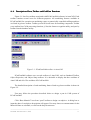
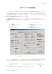
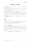
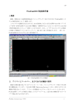
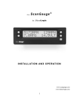
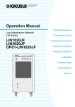
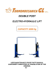
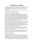
1
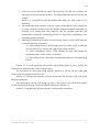
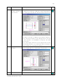
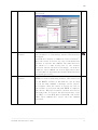
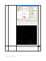
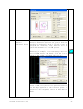
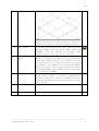
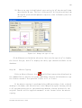
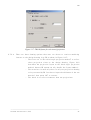
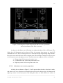
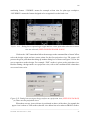
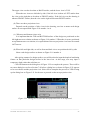
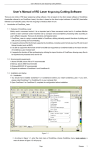
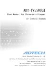
CAD
II
PCadCam2000 Software CAD User Manual
2.1.
Outline
The utilization of PCadCam2000 to perform machining operation on plate or square-like
raw material on machining center will be explained in this chapter.
It is important to have AutoCAD2000 or higher version of AutoCAD running for this
cad-cam software to be operational. Some functions of AutoCAD are also used in
PCadCam2000, therefore allowing the execution of AutoCAD menu.
PCadCam utilizes its own menu for user to run CAD, CAM or Database system. Figure 1
shows the starting display of PCadCam2000 software.
Figure 1
Starting display of PCadCam2000 software.
―――――――――――――――――――――――――――――――――――――――――――――
PCadCam International (PCI)
1
CAD
2. 2.
Description of Icon, Toolbar and Cad/Cam Functions
Functions
Figure 2-1 lists five toolbars associated with PCadCam2000 software in AutoCAD. Each
toolbar contains several icons for different purposes. All machining features available in
PCadCam2000 for operation on machining center or numerically controlled milling machines
are listed in pfeature toolbar. Toolbar pcad will list all icons for modeling component. Toolbar
pcam toolbar lists CAM processing functions, fr lists the feature recognition utility, and putility
toolbar lists the database utility.
Figure 2-1. PCadCam2000 toolbars in AutoCAD
PCadCam2000 software uses several toolbars of AutoCAD; such as Standard Toolbar,
Object Properties, and Object Snap toolbars. It is advisable to display the three toolbars of
AutoCAD and all of five toolbars of PCadCam2000.
The detailed description of each machining feature listed on pfeature toolbar is shown in
Figure 2-2.
User may follow the procedure described below to design a part in CAD system of
PCadCam2000.
Click “Base Material” icon from “pcad” toolbar to design a workpiece. A dialog box to
input the data of a workpiece description will appear. User may choose a common name for the
Material Name as a default, or click on the drop down menu
―――――――――――――――――――――――――――――――――――――――――――――
PCadCam International (PCI)
2
CAD
Figure 2-2. Description of machining features
―――――――――――――――――――――――――――――――――――――――――――――
PCadCam International (PCI)
3
CAD
1. to choose several materials provided. The next step is for the user to choose the
dimension of the raw and final product. The final product thus defined is termed as
“BASE”.
BASE is a rectangular parallel hexahedron that binds the final product to be
machined.
2. The machining surface quality of the six surfaces of the BASE can be assigned to
be rough, medium or finish when the Product dimension (BASE dimension) is
designed to be smaller than Raw Material. The NC program generated will
automatically include the machining process for each surface depending on the
machining quality assigned.
3. Modeling of Machining Features on each design surface of the BASE material,
repeat the following operations:
2-1. Select design surface: Click Design surface icon from “pcad” toolbar and
user can choose top, bottom, left, right, front or back surfaces
2-2. Select machining feature: Click pfeature to select and design the
machining feature on the surface of the base.
2-3. Select the position, dimension or machining method for each machining
feature.
Section 2.3 of CAD Operation will provide self-learning guide for users. Follow the
instruction to understand the CAD/CAM operation.
The description of cutter path using polyline function or 2D cut off and cutter path
features will be explained on Section 2.4.
Section 2.5 explains the sequence to model an optional 3D perform work piece using
Boolean operations.
The operation to convert a 2D design by other CAD system in PCadCam2000 utilizes
Feature Recognition System. The detail will be explained in Section 2.6.
Section 2.7 and thereafter will describe the CAM and other operations.
―――――――――――――――――――――――――――――――――――――――――――――
PCadCam International (PCI)
4
CAD
2.3
2.3. SelfSelf-Learning Guide for CAD Operation
First time user is recommended to follow a sample exercise presented below by
performing the step-by-step guidance as numbered. Figure 2-3 shows the sample exercise to
model two square slots, one 2-sided pocket, one 4-sided pocket and four blind bore features on
the top surface with four M12 taps overlaid concentric to the bore. The machining origin is
assigned at the left lower corner.
Figure 2-3. Sample of CAD operation exercise.
Start PCadCam2000 software, and complete each step on Table 1 to finish the sample
design.
Table 1.
1. StepStep-byby-step CAD Operation
Step
1
2
3
Description
Start ACAD
Note
Double click the icon as shown on the right.
Icon
Wait while AutoCAD loads PCadCam2000 and the
Database.
Base, material and Click the icon as shown on the right to design a base
dimension design
material. A dialog box below will appear and input
the base dimension. The base material data can be
viewed again anytime. The data shown on the left part
of the dialog box to input the raw material dimension
can be revised. The data on the right part is the
product data, and cannot be revised later on.
―――――――――――――――――――――――――――――――――――――――――――――
PCadCam International (PCI)
5
CAD
4
Origin Shift
Click the icon as shown on the right when it is
required to move the origin from the bottom left
corner to another point. Input the data on a dialog
box as shown below. The origin coordinate can be
revised anytime during CAD operation.
The orientation for each surface is shown below. Top
and bottom surfaces are switched from each other by
rotation either around X-axis (top to bottom) or
around Y-axis (left to right). It depends of the
setup specified in the Utility display of CAM
―――――――――――――――――――――――――――――――――――――――――――――
PCadCam International (PCI)
6
CAD
database main menu. Switching among four side
surfaces (Front, Back, Left and Right surfaces) is
by rotation around Z-axis.
5
6
7
Selection
or Click the icon as shown on the right.
revision of design
surface
Assign
design The dialog box to select the design surface will
surface
appear.
Assign top as a Double click on “TOP” or click on “TOP” and “OK” once.
design surface
Other surfaces will be displayed by hidden lines.
Adjust the setting of dash line interval if it
appears as solid line. The setting will be adjusted
automatically as a default based on the size of the
worpiece base. Perform the next command input when
manual setting is required.
Type in:
“ltscale”
and push ENTER. The present setting value will be
shown (ex. 0.06). Input the desired value (ex. 0.2)
and push ENTER to execute the command. Press ENTER
―――――――――――――――――――――――――――――――――――――――――――――
PCadCam International (PCI)
7
CAD
8
Square slot
feature design on
top surface
again to repeat the same command to further revise
the value.
Click on the icon as shown on the right to design
a square slot feature. Input the required parameter
in a dialog box below for the horizontal direction
User may click OK to complete the design. However,
since the next feature to be designed will also be
a slot feature, click REPEAT to display the same
dialog box.
Note:The repeat function is only applicable to the
same design surface. It cannot be used to design a
same feature on a different surface.
slot Click the icon as shown on the right to repeat the
same feature but in a different orientation.
9
Repeat
feature
10
Two-sided pocket
Click the icon as shown on the right, and input the
―――――――――――――――――――――――――――――――――――――――――――――
PCadCam International (PCI)
8
CAD
design
machining parameter required as shown in a dialog
box below.
Edit a machining Click the icon (EDIT) as shown on the right to revise
feature
the parameter on a machining feature that has been
designed.
AutoCAD will display a command to “Select Feature”.
Move the cursor to select any line of the machining
feature to execute the command. The same data will
be shown in a same dialog box of the feature
selected. Revise the data accordingly, click OK to
complete. This command can also be applied for data
reconfirmation on machining features that have been
designed previously.
Delete a machining Type in “e” or “erase” in the command input and push
feature
ENTER to erase a machining feature. The erase icon
in the MODIFY toolbar of AutoCAD can also be used
to run the same command. A message “select object”
will appear. Move the cursor to select any line of
the feature to selected and push ENTER to complete
the delete. Multiple features could be selected at
the same time. To recover the deleted feature, type
in “UNDO” or click EDIT menu of AutoCAD, and choose
UNDO. This command will cancel the last command
executed.
―――――――――――――――――――――――――――――――――――――――――――――
PCadCam International (PCI)
9
CAD
11
12
Blind bore design
Rectangular Array
Click the icon as shown on the right to display the
following dialog box, and supply the necessary data.
Click on “REPEAT” to add another blind bore or “OK”
to complete the design.
Click the icon as shown on the right.
Move the cursor to select the object to be copied
in array, and push ENTER. Choose “R” for rectangular
or “P” for circular array followed by ENTER. Input
the number of raws (Y-axis) and columns (X-axis),
as well as the distances. Push “ENTER” for each data
input.
WE NEED ACAD2002
ENGLISH DIALOG BOX
Click the “Select Object” icon and move the cursor
to select the object to copy. Push ENTER to finish
selection.
Display will resume the dialog box in the above.
Click on “PREVIEW” button, second from bottom on the
right corner.
―――――――――――――――――――――――――――――――――――――――――――――
PCadCam International (PCI)
10
CAD
If approved, click on “ACCEPT” then four blind bores
will be modeled as shown in the above.
13
Grouping
Click the icon as shown on the right to group or
ungroup features.
Follow the instruction on the command line to select
the feature on an active surface. The feature
selection can be done individually or apply a window
to cover the feature area. When applying a window;
click the icon and select a feature, then apply a
window to cover the whole features to be grouped.
Push “ENTER” to complete the task. The line of the
features will be changed to red. Push “ENTER” again
to complete.
Group Confirmation After group/ungroup icon is clicked; choose one
feature in the group and push “ENTER”. The
highlighted feature and others in the same group
will change color to red, and a dialog box associated
with the feature will appear for confirmation.
At the same time, the command line of AutoCAD will
display a question of “Group more feature [G] or
Ungroup existing feature [U]”. Press “G” for
confirmation followed by “ENTER” twice to complete.
Adding Group
When adding a feature to a group becomes necessary,
select “G” and push “ENTER” once. Click the feature
to be added and followed by “ENTER” twice.
―――――――――――――――――――――――――――――――――――――――――――――
PCadCam International (PCI)
11
CAD
Ungrouping
Select “U” and “ENTER” to cancel the grouping
command. A statement “select or all [A/S] features
to ungroup” will appear. Press “ENTER” to ungroup all
features.
Press “S” and click the feature or
features to be removed from the group followed by
“ENTER”
Note : Pay attention when grouping hole features
14
Overlap
design
belonging to different heights : namely having
different (W). When some hole features with
different W is grouped together; the NC program will
be generated with the same process cycle therefore
“W” value will be ignored. Never group hole features
with different W value.
features Click “EDIT” and select any blind bore hole that has
been designed and grouped in the above step 13. Push
“ENTER” or right click the mouse. The following
dialog box will appear.
Select “YES”. The original blind bore feature dialog
box will appear. Change blind bore to tap (M12) in
feature name of the pull down menu, and input the
data accordingly:
―――――――――――――――――――――――――――――――――――――――――――――
PCadCam International (PCI)
12
CAD
Select “Repeat” button and four M12 tap features will
be designed in the position of blind bore holes.
Click “Cancel” to complete.
15
Four-sided pocket Click the icon as shown on the right to design a
design
four-sided pocket feature. The following dialog box
will appear. Input the data accordingly.
―――――――――――――――――――――――――――――――――――――――――――――
PCadCam International (PCI)
13
CAD
16
Face
feature Face feature design is not required if the raw
(surface
material dimension has been set greater than the
machining) design product, as assigned in step 3. In such a case, NC
program for machining side surfaces will be
generated automatically in CAM process.
However, for example, to face machining lower left
part of 35mm square, 2mm depth; click the icon as
shown on the right, and input the data as :
Later in CAM, tool path will be generated starting
on the edge opposite to the reference point, in
parallel to the length d1, and in the down milling
mode.
―――――――――――――――――――――――――――――――――――――――――――――
PCadCam International (PCI)
14
CAD
17
18
19
20
Switch to view ALL
Change the view as in steps 5 and 6 to view ALL to
display all surfaces with the designed features.
Save design
Click the icon as shown on the right to save the file.
As for example, save the above sample design as
“SAMPLE”, and the AutoCAD will assign “dwg”
automatically to the file as its extension.
Change to solid The sample design has been completed and saved.
model
However, to display the sample file as in Figure 2-3,
change the display (steps 5, 6) to “SOLID”. User can
view the part in an optional orientation by typing
in VPOINT in the command line followed by ENTER.
Input the value of XYZ to the desired orientation
followed by ENTER. Type in HIDE to put out the hidden
line followed by ENTER.
FINISH
Return the design surface to drawing mode (the
display before SOLID) to revise or add machining
features, and also to continue to CAM process after
completing CAD design. Save the file (step 17) after
any revision.
―――――――――――――――――――――――――――――――――――――――――――――
PCadCam International (PCI)
15
CAD
Step 21. Tap Feature Design
(1) Click the Tapped Hole Feature icon to display the following dialog
box of Figure 2-4.
Figure 2-4. Tap feature dialog box
(2) User can click on the pull down menu, next to “d1”, to display all type
and size of taps available as listed in CAM database.
Figure 2-5. Display the size of tap
―――――――――――――――――――――――――――――――――――――――――――――
PCadCam International (PCI)
16
CAD
(3) When a tap type is highlighted, user can key in “m” then the pull down
menu display M-type. The size of M-type will be listed starting from
M3 regular pitch thread upward in tap size, then followed by the fine
pitch ones.
Figure 2-6. Change the type of tap
Click OK button to finish the selection. User can also type in “p” to display
the list of Pt-type, and “u” to display the unify type threads available in the
database.
Step 22.
Mirror Copying
Click on Mirror Feature icon
and follow instructions displayed on
the command line to specify one or more machining features and then mirror copy
the feature around a line parallel either to X- or Y-axis.
If the mirror copying is performed after CAM processing of the original
drawing is finished, user does not have to do CAM process again, but may proceed
to NC program generation so that machining methods already defined for the
original feature will be applied automatic to the feature after the mirror
copying.
―――――――――――――――――――――――――――――――――――――――――――――
PCadCam International (PCI)
17
CAD
Step 23
Add Feature Design
Before continuing to the next process; try to revise or add some machining
features (on the design surface LEFT, FRONT, etc), so that the part will include
more features as shown in Figure 2-7.
Figure 2-7. Adding features on the sample exercise
2.4
2.4. Using Polyline as Auxiliary Machining Features
Features
The polyline function of AutoCAD can be used to design two auxiliary machining
features, namely cut off and cutter path features. A chamfer can also be assigned in
the cut off machining feature. In CAD process, polyline function will only design an
contour of a feature, and at this point; the machining process cannot be viewed.
User will use polyline to draw the contour then choose the cut off or cutter path
icon to start.
2.4
2.4.1. Design a feature with AutoCAD
AutoCAD polyline function
•
Polyline is a function that makes combination of straight and circular lines
possible. Type in “pline” or “pl” in AutoCAD command line followed by ENTER
to start drawing one.
•
Follow the directions appear in command line to draw the polyline.
•
It is important to consider several items as listed below in drawing a
polyline:
•
Cut off machining will take place offset on the left side (removing
material on the left) of the polyline. When a polyline contour will be
designed as the binding geometry of the final product; draw the polyline
―――――――――――――――――――――――――――――――――――――――――――――
PCadCam International (PCI)
18
CAD
in a clock wise direction (CW). When the polyline contour is designed as
a binding geometry of a pocket to be removed, design the polyline in
counter clock wise direction (CCW).
•
The polyline can be either an open contour (start cut from the side), or
an close loop (start cut in Z-axis). Confirm the clearance of start and
end points of the polyline for cutting tool to approach the workpiece when
the polyline is open (not a close loop).
The start and end points should be a straight line (not a circular arc)
of the polyline. It is an important condition for the CAM process to design
the cutting tool path when it approaches the workpiece. The cutting tool
will start at a point 5mm offset to approach, and the finish point will
also be 5mm offset.
2.4
2.4.2. Click the cut off or cutter path icon
•
After completion of a polyline design, make sure to click on either cut off
or cutter path icon before conducting any other operation.
•
The dialog box of either cut off or cutter path will appear, and the user
will select machining method and input the value of d3 parameter.
•
It is possible by using MODIFY(M) icons to rotate, or copy a polyline in cut
off or cutter path features using polyline, however the EDIT(E) icons cannot
be used. It is not advisable, however, to mirror copy using MODIFY(M) icon
because it mirror copies the geometry of polyline as well as the CW/CCW sence.
For the purpose of accommodating mirror copy including CAM requirements, a
special Mirror Copy capability is prepared among PCAD icons as described
previously in Step 22.
•
When selecting the cut off icon; notice that the d3 parameter is not the
depth of cut but it is the thickness of the workpiece material. The depth
of the cut off will be decided by the data assigned in the database.
•
By selecting the chamfer in machining method, the polyline will be chamfered
along the line. In such a case, the d3 will be the data for the width of the
chamfer.
•
When selecting the cutter path icon; the width of cutter path will be assigned
temporarily. Later in CAM process will the width of cutter path be given
according to the cutting tool diameter chosen by the user.
2.4
2.4.3. Nesting
―――――――――――――――――――――――――――――――――――――――――――――
PCadCam International (PCI)
19
CAD
Nesting can be performed on cut off or cutter path operation using polyline, as
well as on other machining features whenever it becomes necessary to copy, move, rotate
or mirror a feature.
Select the object of polyline or machining feature to be copied, moved, rotated
or mirrored once. Do not select the object repeatedly. Do no use the window or group
selection function provided by AutoCAD to select the object.
2.4
2.4.4. Operation data for cut off machining
User can change the operation data for cut off machining in a similar way as on
the other machining features. Refer to Figure 2-8 that describes the data generated
and its machining sequence in three operations.
Operation 1
Tool
Tool: 18mm roughing end mill
Spindle speed: 710rpm
Axial depth of cut: 15mm
Feed rate: 125mm/min
Down cut
Coolant
Product
2.0
Operation 2
Tool
Tool: 16mm square end mill
Spindle speed: 600rpm
Axial depth of cut: 24mm
Feed rate: 150mm/min
Up cut
Coolant
Product
0.5
Operation 3
Tool
Product
Tool: 16mm corner end mill
Spindle speed: 2500rpm
Axial depth of cut: 2.4mm
Feed rate: 125mm/min
Down cut
Airblow
0.1
*Material: SS41
―――――――――――――――――――――――――――――――――――――――――――――
PCadCam International (PCI)
20
CAD
Figure 2-8. Example of machining operation sequence for cut off with machining method of “Medium,
0.1mm from bottom, product fixed”
Parameter d1 will be used for the offset of depth of cut of the excess material
in rough or medium finish machining. The value of parameter d1 is not a design variable
therefore the value should not be given in CAD process.
For example, d1=d1+0.2 is set as a default in the operation database so that the
rough machining process will leave 0.2mm of excess material on the boundary of cut off
line.
―――――――――――――――――――――――――――――――――――――――――――――
PCadCam International (PCI)
21
CAD
2.5
2.5. User to Define Inclined Design Surface
Although the BASE material is a rectangular shape, user can define an inclined
surface on the BASE with an optional angle (other than 90o) as explained herewith. There
will be two methods that utilizes the AutoCAD function of UCS (Universal Coordinate
System), and it will be explained in following two sections.
2.5.1
2.5.1.
5.1. ThreeThree-point Method
Figure 2-9. Three-point origin shift method
It is a method convenient to set an inclined surface rotated on the base surface
around either one of A, B or C axes
User will key in three values XYZ by the following steps:
1.Specify the position of origin of the new XYZ coordinate system.
2. Specify the position of one point on the positive X axis direction of the new
coordinate system.
3. Specify the position of one point on the positive Y axis direction of the new
coordinate system.
By specifying three values in the above, the direction of the Z axis of the new
coordinate system will be decided by right hand screw rule. In other words, when X axis
is rotated toward Y axis the direction of the advance of right hand screw is the direction
of Z axis.
―――――――――――――――――――――――――――――――――――――――――――――
PCadCam International (PCI)
22
CAD
The area of the part having positive value of Z axis from the point 1 as specified
in the above belongs outside the part, and therefore it is sliced and deleted from the
display. When the Z value is minus; the range will be inside the work piece.
When the external geometry (BASE) of the part is designed as a rectangular parallel
hexahedral, the procedure is as follows:
1.
Click on the icon to select the design surface, and select “ALL”.
2.
Key in “UCS” in command line input and press ENTER. Key in “N” and ENTER,
and then key in “3” and ENTER.
Key in XYZ values of the point 1; each separated by a comma and press
ENTER.
3.
4.
5.
6.
7.
Key in XYZ values of the point 2; each separated by a comma and press
ENTER.
Key in XYZ values of the point 3; each separated by a comma and press
ENTER.
(This step is necessary only for AutoCAD2005 and above. This step may
be omitted when using AutoCAD2004 or below)
Key in “UCS” and then push “ENTER”. Key in “S” and push “ENTER”. Key in
“A” (actually the key may be any alphabet) and push “ENTER”.
Click the “Design Surface” icon, and click on “Create” button. A dialog
box of Figure 2-10 will appear listing all of the origin point to confirm
the new surface. Give a name of the design surface, and select the color
for machining features that will be generated on the new surface (red
is a default). Click OK then a small message window will appear to ask
if user want to display the cut base material. Select “YES”.
Figure 2-10. Confirmation of the new surface generated
8.
9.
Click “ALL” and OK to display the outline of the new cut base material.
Click on the “Design Surface” and select the name of the new surface.
User can proceed to design machining features on the new surface.
―――――――――――――――――――――――――――――――――――――――――――――
PCadCam International (PCI)
23
CAD
2.5.
2.5.2.
5.2. A Method to specify
specify two points on the surface normal.
It is a method convenient to set an inclined surface rotated around either
two of A, B or C axes
The description of the method is shown in Figure 2-11.
Figure 2-11. Two-point relation on principal line method
User will key in three sets of XYZ values in sequence.
1. Specify XYZ values of one of two points lying on the surface normal having
smaller (or more negative) Z value on the new coordinate system.
2. Specify XYZ values of the other point lying on the surface normal having
greater (or less negative) Z value on the new coordinate system.
3. Specify distance from the point 1 in the above to the new design surface.
The intersection of the surface normal specified by 1 and 2 in the above with
the new design surface will be the origin of the new coordinate system. X axis
of the new coordinate system will be parallel to the XY plane (BOTTOM surface)
of the global coordinate system.
The area of the part having positive value of Z axis from the origin point belongs
outside the part, and therefore it is sliced and deleted from the display. When
the Z value is minus; the range will be inside the work piece.
When the external geometry (BASE) of the part is already designed as a rectangular
―――――――――――――――――――――――――――――――――――――――――――――
PCadCam International (PCI)
24
CAD
parallel hexahedral, the procedure is as follows:
1. Click on the design surface icon, and select “ALL”.
2. Key in “UCS” in command line, and press ENTER. Key in “N” and press “Enter”
key, and key in “ZA” followed by pressing “ENTER” key.
3. Key in the XYZ values of the point 1 in the above, separated by a comma,
and press “ENTER” key.
4. Key
and
5. Key
and
in the XYZ values of the point 2 in the above, separated by a comma,
press “ENTER” key.
in “UCS” once again followed by pressing “ENTER” key. Type in “N”
press “ENTER” key. Input the distance from the point 1 in the above
to the new design surface by giving Z axis coordinate values.
For example, if the distance is “a”, key in “0,0,a” separated by a comma
and press “ENTER” key.
6. (This step is necessary only for AutoCAD2005 and above. This step may
be omitted when using AutoCAD2004 or below)
Key in “UCS” and then push “ENTER”. Key in “S” and push “ENTER”. Key in
“A” (actually the key may be any alphabet) and push “ENTER”.
7. Click the “Design Surface” icon, and click on “Create” button. A dialog
box of Figure 2-10 will appear listing all of the origin point to confirm
the new surface. Give a name of the design surface, and select the color
for machining features that will be generated on the new surface (red
is a default). Click OK then a small message window will appear to ask
if user want to display the cut base material. Select “YES”.
Figure 2-10. Confirmation of the new surface generated
8.
9.
Click “ALL” and OK to display the outline of the new cut base material.
Click on the “Design Surface” and select the name of the new surface.
User can proceed to design machining features on the new surface.
―――――――――――――――――――――――――――――――――――――――――――――
PCadCam International (PCI)
25
CAD
2.6
2.6. Modeling PrePre-form Material
Pre-form material made by welding, foundry or other processes could be modeled
as a raw material using INTERSECTION, SUBTRACT and UNION operations on a
rectangular parallel hexahedron BASE. The process is shown in the upper part
of Figure 2-12. When modeling a perform raw material, the machining features
applied will not be processed in CAM operation. Upon completion of the raw
material modeling, user can continue the process of adding machining features
to design the final product, as shown in the lower part of Figure 2-12. CAM
operation will only generate an NC program for the machining features data
applied at this stage to be machined on Machining Center.
Figure 2-12. Raw material modeling process in P-CAD
The incoming sections will explain some detail explanations regarding the raw
material modeling.
2.6
2.6.1 Raw Material Design
Start the AutoCAD program and bring up the dialog box to display the base material
design. Input same value in XYZ direction in raw and product columns. When the
―――――――――――――――――――――――――――――――――――――――――――――
PCadCam International (PCI)
26
CAD
raw and product have the same input value; six surfaces in the base material
quality will automatically be given “NONE” value as shown in the lower part of
the dialog box. Click OK button to finish the base material design.
Design any machining features on a surface of the BASE to model the raw
material by running an operation (called “Boolean Operation”) of “union” to add
a body, “subtract” to remove or “intersection” to overlap the body. The icon of
these operations is located in PCAD toolbar.
The display of the machining feature designed will have its specific color
at the beginning, and it will change into white as it is merged with the base
material.
As an example, the illustration in Figure 2-13A describes the union
operation to model a round bar added at the top surface of a rectangular parallel
hexahedral body.
A
。
blind bore
union
raw material
new raw material
B
。
blind bore
subtract
raw material
new raw material
―――――――――――――――――――――――――――――――――――――――――――――
PCadCam International (PCI)
27
CAD
C
。
blind bore
intersect
new raw material
raw material
Figure 2-13. Description of Boolean Operation for Union, Subtract and Intersection
Figure 2-13B describes the subtract operation to create a hole in the new raw
material model by using a blind bore feature. The bottom part of Figure 2-13C
describes the intersection operation to model a round bar from the base material
by using a through bore feature.
Various machining features can be used repeatedly to design a preform raw
material. User can run the union, subtract or intersection operation by clicking
the icon or type in (union, subtract or intersection) in command line and push
ENTER. Follow the instruction in command line to select the object. User should
select the base material before machining feature when doing the union, subtract
and intersection operations. Press ENTER after each selection.
2.6
2.6.2 STL File Generation
The preform raw material model built, as explained in Section 2.6.1, can be
saved in STL format file to be used in Super Verify software for NC program
verification after CAM process is completed.
To save the file in STL format; type in “stlout” in command line and press ENTER.
Follow the instruction accordingly and create a name for the file.
2.6
2.6.3 Machining Feature Design
Upon completion of the preform raw material model, user can continue to design
machining features on the model as described in the lower part of Figure 2-12.
―――――――――――――――――――――――――――――――――――――――――――――
PCadCam International (PCI)
28
CAD
The machining features will be displayed in color and will be processed in CAM
operation to generate the NC generation.
Input a negative value “W” column in machining feature dialog box when the user
needs to shift the origin of machining features lower than the BASE surface.
The value is the distance from the surface. Input a positive one when the origin
point is located higher than the surface.
2.6
2.6.4 Closing CAD Operation
User should examine carefully the two factors explained in this section after
completing CAD operation and before continuing to CAM operation.
1. Origin point for each design surface.
The last origin point given for each design surface will be processed
in CAM operation as the NC Program Reference Point (NCPR), that is X=0,
Y=0 and Z=0. Refer to Section 2.3 step 4 to display the origin point for
each design surface or to shift the point if necessary. Save the design
and proceed to CAM operation.
2. Save the design.
User should save the file after any revision done on the design as
explained in Section 2.3 step 17.
2.7
2.7. Feature Recognition (FR) Input
None of the previous steps in P-CAD operation will be used to design a part when
using this function. Feature Recognition or FR is a function to import a file in DWG
or DXF format of two-dimensional CAD drawing that is used widely in industry.
FR software is not meant to provide a multi-function system in principal, but user
can make good use of this software in PCadCam as an auxiliary input function. User has
to register the sign or drawing method of the two-dimensional CAD system in the drawing
database to start FR software. Refer to the last chapter of Feature Recognition System
for detailed explanation.
PCadCam system calls the boundary of a part as BASE that represents a rectangular
parallel hexahedral (plate or block). When using FR system, user will assign two corners
from one projection in the drawing, and the system will build the BASE automatically.
―――――――――――――――――――――――――――――――――――――――――――――
PCadCam International (PCI)
29
CAD
FR will recognize the position and shape of any hole, pocket, step and slot features
designed on the BASE then supplies the data to P-CAD. Data input from FR to P-CAD can
be done in a simple way. It is most effective when there is a great number of shape
or feature designed.
2.7.1.
2.7.1.
File Input Preparation
Drawing from 2-D CAD system has to be prepared in either DWG or DXF format to be
imported into FR system. The drawing should contain projection of the part that will
show all the machining features to be processed in CAM operation. Erase or remove the
frame of the drawing, table, or dimension that exists in the drawing before starting
FR operation.
2.7.2.
Input the Drawing File into FR
Follow the steps below to input a drawing file into FR.
2.7.2.1. Start PCadCam software.
2.7.2.2. Open the file using OPEN function of AutoCAD if the drawing is prepared in DWG
format. User has to import the drawing in DXF format by clicking the “DXF Input”
icon in the “fr” toolbar, as shown in Figure 2-14. A dialog box to locate the
file will be shown in Figure 2-15, then click OPEN. An example of imported design
drawing is shown in Figure 2-16.
Figure 2-14. Feature Recognition Toolbar
―――――――――――――――――――――――――――――――――――――――――――――
PCadCam International (PCI)
30
CAD
Figure 2-15. DXF file import dialog box
Figure 2-16. Example drawing imported from DWG or DXF file
2.7.2.3. User needs to do further preparation on the projection drawing for the system
to recognize the machining feature design. Click on “fr” icon to bring up a dialog
box as shown in Figure 2-17.
―――――――――――――――――――――――――――――――――――――――――――――
PCadCam International (PCI)
31
CAD
Figure 2-17. FRCAD frame for selection of projection
2.7.2.4. There are three drawing options that user can choose to retrieve machining
feature on the design drawing into FR as shown in Figure 2-17:
-
The first one is “The third angle projection method” to select
three projection views on the design drawing. Figure 2-18
describes the projection layout on the third angle projection
method; however FR system can only handle the layout number 1.
-
The second one is used only there is only one projection drawing
to be processed by FR. User has to input the thickness of the raw
material then press “OK” to execute.
-
The third is to select from more than two projections.
―――――――――――――――――――――――――――――――――――――――――――――
PCadCam International (PCI)
32
CAD
FRONT
RIGHT
BACK
(前面)
(右)
(後面)
BOTTOM
TOP
(下面)
(上面)
6.Both side and front/back view are placed on the side.
TOP
BOTTOM
(上面)
(下面)
5.When Top and Bottom view exist.
LEFT
RIGHT
BACK
(左面)
(右面)
(後面)
TOP
TOP
(上面)
(上面)
3.When the side view is placed at
4.When the side view is placed at
the upper right.
the upper left.
TOP
TOP
(上面)
(上面
FRONT
RIGHT
LEFT
FRONT
(前面)
(右)
(左面)
(前面)
1.When the side view is placed at
2.When the side view is placed at
the bottom right.
the bottom right.
Figure 2-18.Layout and name of view on Third Angle Projection Method
―――――――――――――――――――――――――――――――――――――――――――――
PCadCam International (PCI)
33
CAD
2.7.3.
Design Origin and Two Corner Selection on the Base Material
User has to select three points on one projection drawing that represents the
whole view area for the FR system to recognize the designed machining features. The
method to assign those points will be explained in the following section.
2.7.3.1. Selection on three projections based on the third angle projection
When the first selection on Drawing Options dialog box is highlighted as shown in
Figure 2-17, and followed by pressing the “OK” button; a new dialog box will appear as shown
in Figure 2-19 for the user to select two points on top and right side views.
Figure 2-19. Dialog box to input two points on top and side views when the third angle
projection method is implemented
2.7.3.2. Selection on a single projection
When the second selection on the dialog box shown on Figure 2-17 is highlighted, the
thickness of the raw material is inputted, and followed by pressing the “OK” button; a new
dialog box as shown in Figure 2-20 will appear.
―――――――――――――――――――――――――――――――――――――――――――――
PCadCam International (PCI)
34
CAD
Figure 2-20. Dialog box to input design origin and two corner point data
when Conventional: One View is selected
As shown in the figure; user will assign one origin point then click on OK button. The
dialog box will disappear and user has to follow the message that appears on AutoCAD
command line. The first is message will be to select the design origin using snap function.
Move the cursor and click once on the selected point. The messages continue to select a point
on left bottom corner and right top corner. The point selection sequence will be as followed:
•
Design origin: Select one point on the view.
•
•
Left bottom corner: Select one point on the view.
Right top corner: Select one point on the view.
2.7.3.3. Selection on two or more projections
A dialog box as shown on Figure 2-21 will appear when the above selection is made,
and same as one view selection; user should select one point for design origin, left bottom and
right top corners. At the lower part of the dialog box, there are three choices on surface of
―――――――――――――――――――――――――――――――――――――――――――――
PCadCam International (PCI)
35
CAD
machining feature. “VISIBLE“ means for example a front view for plate-type workpiece,
“INVISIBLE“ means the feature designed to be recognized is on the back view.
Figure 2-21. Dialog box to input design origin and two corner point data when two or more
view are selected (NEED ENGLISH DIALOB G BOX)
Click on the “OK” button then follow the message on the command line of AutoCAD to
select the design origin and two corner points for the first projection view. FR system will
process the given point data then bring up another dialog box as shown on Figure 2-22 for the
user to appoint a surface design. For example “TOP” surface is given to the projection view.
Besides naming a design surface to a projection view, refer to the condition below when there
are several views exist.
Figure 2-22. Dialog box to assign a design surface on a projection view (NEED ENG DG BOX)
(a) There are two projection views
When there are two views with one is positioned on above of the other; for example the
upper view is taken as TOP surface, then the view below has to be taken as FRONT surface.
―――――――――――――――――――――――――――――――――――――――――――――
PCadCam International (PCI)
36
CAD
The upper view can also be taken as BACK surface, and the lower view is TOP.
When the two views are laid side by side; if the left view is taken as LEFT surface then
the view on the right has to be taken as FRONT surface. If the left view on the drawing is
taken as FRONT surface, then the view on the right will become RIGHT surface.
(b) There are three projection views
Depends on the position of side views in the drawing, user has to name each design
surface in correspond with Figure 2-18 number 1 to 4.
(c) When top and bottom views exist
It is important that the TOP and BOTTOM surface of the design are positioned on the
left/right turn over relation as shown on Figure 2-18 number 5. When the views are positioned
on top/bottom turn over relation; it is required that of the one projection view has to be rotated
180o later on.
(d) When left and right side, as well as front and back views are positioned side by side
Name each design surface as shown on Figure 2-18 number 6.
After giving a name of a design surface, user will be asked to input the depth of machining
feature on that particular design surface in the lower box. At this stage, user may input a
temporary depth value then edit later on.
Click OK button on the dialog box of Figure 2-22 to complete the process. There will be
two more dialog box (refer to Section 7.4) before a dialog box as shown in Figure 2-23 appears
to let user choose another projection view. Select NO to complete the process or YES to bring
up the dialog box on Figure 2-21 for the user to proceed on the next projection view.
Figure 2-23. Dialog box to select the next projection view to be imported
―――――――――――――――――――――――――――――――――――――――――――――
PCadCam International (PCI)
37
CAD
2.7.4.
FR Operation
FR system will analyze the projection drawing data, however when there is one or more
layer that is not registered in the database, a pop up dialog box will appear as shown on Figure
2-24. User will assign the line type (solid, hidden, auxiliary or none) on each identified layer in
the dialog box. The system will highlight the line in red or blue color on the background
display.
Figure 2-24. Dialog box to confirmed the non-registered layer in the drawing database
The system will bring up another dialog box as shown on Figure 2-25 when it detects a
non-registered feature symbol in the drawing database. User will assign whether the feature
belongs to the Top or Bottom surface. The system will highlight the feature in red or blue color
on the background display.
Figure 2-25. Dialog box confirmed the non-registered feature in the drawing database
―――――――――――――――――――――――――――――――――――――――――――――
PCadCam International (PCI)
38
CAD
2.7.5.
Polyline Operation
Figure 2-26 displays a dialog box for polyline selection that will appear when FR system
detects an existing polyline in the two-dimensional drawing. The system will bring up the
dialog box only if the operation of polyline generation is registered in the system setting data in
the drawing database.
Figure 2-26. Dialog box to confirm polyline selection
Add Polyline
[Refrain from using this button temporarily because of technical problems. User is
advised to use next function “Select All”.]
This button is used to recognize line elements that exist in the drawing but not yet listed as polyline in
the dialog box.
Polylines that need to be processed by either “Cut Off” or “Cutter Path” operation are listed in the dialog
box by following procedures.
Click on “Add Polyline” button, a message is displayed“test of bully”. Escape from the message by
clicking on “OK”button.
Then, click on a line element in the drawing that user wants to add.
Name, type (Cut-off or Cutter path), sence (CW or CCW), surface, and depth data are automatically
―――――――――――――――――――――――――――――――――――――――――――――
PCadCam International (PCI)
39
CAD
entered in the dialog box.
Feature Name to assign a machining operation of the polyline.
If the line element is not recognized as a polyline, a message is displayed. If the user wants to process
the line element as the polyline, the line element has to be modified to polyline by conducting
procedures described in succeeding section 2.7.6, and return to section 2.7.2.3.
Select All
Push this button for the system to select all the polyline exist in the drawing and show
them in the dialog box. User can choose each polyline or select them in a group to edit,
confirm or delete.
Add Approach
Push this button to add a polyline at the start and end points that will be used
as an approach line of the cutting tool to start and finish machining. Left click
the target polyline on the drawing after pushing the button to display a dialog
box that confirm the
polyline. Fill in the necessary items and press OK button
to execute adding a linear approach line on the polyline. In the case of a close
loop polyline, move the cursor to the command at the left bottom part of the display
then left click to bring up a message that will ask the user to define the inside
or outside of polyline. Move the cursor then left click on the selection.
EDIT
Use this button to revise the selection of polyline type (cut off or cutter path), direction
(CW or CCW) or the thickness of the material. Click the item from the list to be revised
before pressing this button then input the new value to execute.
(Note) a “FATAL ERROR” message will appear when trying to edit design surface of
the polyline at this stage. When editting becomes necessary, do so when the Figure 2-28
of product data appears and edit the surface design number 1 to 6.
DELETE
Press this button to delete a polyline while it is highlighted on the list.
MOVE
Click on this button to move a drawing by adjusting the cursor, left click the mouse then
drag to the new position. Right click to cancel.
REAL TIME ZOOM
Highlight the column in the dialog box using the mouse. Click on this button and the
color of polyline listed in the column will be changed into red. Move the cursor into the
―――――――――――――――――――――――――――――――――――――――――――――
PCadCam International (PCI)
40
CAD
drawing then left click to magnify or reduce the drawing. Right click to cancel.
CANCEL
Click on this button to cancel all the process on the polyline and progress to the next
step.
FINISH
Pressing on this button will carry the polyline data listed in the dialog box and proceed
the process as explained in Section 2.7.7.
2.7.6
2.7.6.
Correction on Results of FR Operation
Figure 2-27 displays the results of FR operation that will appear if machining feature
correction during FRCAD is set in the system setting data of the drawing database. The name,
design surface, position and dimension, etc of automatically recognized machining feature are
listed on the right. It is called a machining feature list. Polyline data will not be included in this
list.
Figure 2-27. Dialog box for correction on results of FR operation
Right click on any column using the mouse pointer to highlight all machining features
on the same position. Left click to highlight each column. It is also possible to highlight by
optional on several columns by pressing SHIFT or CTRL key while clicking the mouse. User
can edit the parameter of the highlighted machining feature shown on the left of the dialog box.
There is a possibility for the system to mistakenly recognized the feature therefore it is
highly recommended for the user to confirm the results with the drawing and correct them
―――――――――――――――――――――――――――――――――――――――――――――
PCadCam International (PCI)
41
CAD
accordingly. User should also correct the depth of feature because the value listed is only
tentative. Highlight each column to revise the position of machining feature (U and V values) as
well as orientation angle. The digit of accuracy for machining feature position (UVW) and
variable (D1 ~ D6) is set to be three decimal point. The system will round off the decimal point
if it is smaller than three. Tap and step-hole only use one digit of accuracy.
Apply
Click this button to modify the decimal point on UVW and parameters of the feature
being highlighted,
Copy & Paste
Press this button and the highlighted column will be copied under the last column with a
new sequential number.
Insert Feature
Press this button and the highlighted column will be inserted to the next one.
Delete
Press this button to delete the highlighted column.
Cancel
Press this button to abort any revision operation made on the machining feature data.
OK
Press this button to end editing operation and P-CAD will generate a text formatted
product data automatically, as shown in Figure 2-28.
Figure 2-28. Example of product data display at the end of FR operation
The display on Figure 2-28 shows the dimension of a finished product, the coordinate
origin of each design surface, and machining feature in sequence. On the column of machining
feature; on the left is the name of the feature followed by design surface, level of finish
machining, top/bottom orientation, chamfer width, position (UVW) then specific parameter
―――――――――――――――――――――――――――――――――――――――――――――
PCadCam International (PCI)
42
CAD
(D1~D6, orientation angle). There will be an additional column when polyline exists.
The file of Figure 2-28 display will be saved in C:\Program Files\PCadCam folder
with “frcad2pcad.txt” name automatically assign. This file name will be overwritten when the
next results of FR operation is generated. Therefore it is recommended to copy and save the file
to a different folder for a record. If polyline exists, the file name given will be “p11.txt” (1 is a
number for polyline, and the 11 is the number of polyline generated), and this file should also
be copied and saved to the same folder. Click on FILE then END or close the window to end
FRCAD operation.
2.7.7
2.7.7.
Import Product Data to PP-CAD
Exit AutoCAD system once upon completion of FRCAD. Restart AutoCAD and click
on “Import PData” icon as shown on Figure 2-14. A dialog box will appear to open a file as
shown on Figure 2-29. Select “frcad2pcad.txt “file name or another name as assigned. Click on
OPEN button.
Figure 2-29. Dialog box to open a product data file
A question will appear on AutoCAD command line: “Confirm machining feature
(Y/N)”. Press “N” (or ENTER) to display all machining feature recognized by FR on a display
as shown on Figure 2-30. Press “Y” followed by ENTER to bring up a dialog box that will
display each machining feature to be edited. Click on OK to switch the dialog box for editing
the next machining feature.
The system will no longer displaying the dialog box once all machining feature have
been reviewed and it will bring up a display as shown on Figure 2-30. The outer part of
plate-like workpiece is a tentative base, as explained in Section 2.7.3 by combining two corners
―――――――――――――――――――――――――――――――――――――――――――――
PCadCam International (PCI)
43
CAD
to recognize XYZ dimension automatically. Click on DESIGN SURFACE icon to switch
between surfaces as shown on Figure 2-31.
Figure 2-30. Example of workpiece built using product data
―――――――――――――――――――――――――――――――――――――――――――――
PCadCam International (PCI)
44
CAD
Figure 2-31. Editing machining feature on FRONT surface design
2.7.8
2.7.8.
Editing Machining Feature on PP-CAD
This section will explain the operation to edit machining feature generated
automatically by FR after they have been imported to P-CAD. All information on the depth
dimension are tentative either it is processed on ONE VIEW or MULTI-VIEW, therefore user
has to correct them according to the design drawing.
Machining method for each feature will also be done at this stage. User should also
decide the type of machining feature and edit accordingly. User can also group multiple similar
features, and use the function of grouping to edit all features at once (Table 1 Step 13).
Press ENTER upon completion of grouping. Perform the same grouping operation on
the other features. Click on EDIT icon, and select any feature that has been grouped previously.
Command line will ask if user wants to edit the group (Y) or the individual feature (N). Input Y
or N followed by ENTER to bring up a dialog box of machining feature as shown on Figure
2-32. Edit the feature accordingly then press on OK button. Figure 2-32 shows an example of
changing the type of machining feature.
―――――――――――――――――――――――――――――――――――――――――――――
PCadCam International (PCI)
45
CAD
Figure 2-32. Operation to change the type of machining feature
The system cannot run CAM operation if a polyline recognized by FE exists since the
polyline is still in 2-dimensional type. Follow the step below to convert polyline into a “Light
Weight Polyline” so that the system can continue to CAM operation.
(1)
Type in “convert” and press ENTER.
(2)
(3)
2.7.9
2.7.9.
Type in “p” and press ENTER.
Type in “a” and press ENTER. Conversion operation is completed
Machining Feature Design not Included in FR
User has to design machining feature that is not included in automatic feature
recognition FR system.
2.7.10
2.7.10.
10. Save Drawing
Click on
save icon to save the file.
―――――――――――――――――――――――――――――――――――――――――――――
PCadCam International (PCI)
46