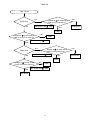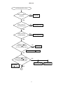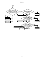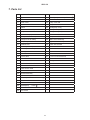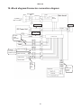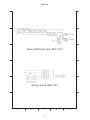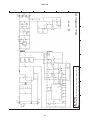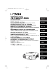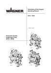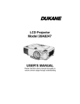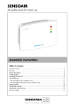
1
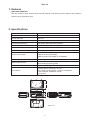
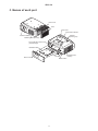
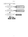
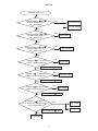
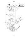
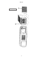
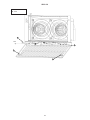
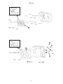
No.0544E
YK
SRC-101
SERVICE MANUAL
(Option for C8)
This Smoke Resistant Case is effective in
suppressing lowering of luminance due to
smoke and dust.
Warning
The technical information and parts shown in this
manual are not to be used for: the development,
design, production, storage or use of nuclear, chemical,
biological or missile weapons or other weapons of
mass destruction; or military purposes; or purposes that
endanger global safety and peace. Moreover, do not
sell, give, or export these items, or grant permission for
use to parties with such objectives. Forward all inquiries
to Hitachi Ltd.
Applicable Models
CP- X870W
CP- X880W
CP- X885W
Caution
Be sure to read this manual before servicing. To assure safety from fire, electric shock, injury, harmful
radiation and materials, various measures are provided in this Smoke Resistant Case. Be sure to read
cautionary items described in the manual to maintain safety before servicing.
Service Warning (SRC-101 AND LCD PROJECTOR)
1. When replace the lamp, to avoid burns to your fingers. The lamp becomes too hot.
2. Never touch the lamp bulb with a finger or anything else. Never drop it or give it a shock. They may
cause bursting of the bulb.
3. This projector is provided with a high voltage circuit for the lamp. Do not touch the electric parts of
power unit (main), when turn on the projector.
4. Do not touch the exhaust fan, during operation.
5. The LCD module assembly is likely to be damaged. If replacing to the LCD LENS/PRISM assembly,
do not hold the FPC of the LCD module assembly.
6. Use the cables which are included with the projector or specified.
Contents
1.
2.
3.
4.
5.
6.
Features ----------------------------------------------- 2
Specifications ----------------------------------------- 2
Names of each part --------------------------------- 3
Regarding the indicator lamp --------------------- 4
Troubleshooting -------------------------------------- 5
Lead free solder------------------------------------ 11
7. Parts list ---------------------------------------------- 12
8. Disassembly diagram----------------------------- 13
9. Connection diagram (Wiring diagram) ------- 19
10.Block diagram/Connector connection diagram--- 25
11. Basic circuit diagram------------------------------ 26
12.Filter maintenance/Changing period/Purchasing --- 29
SPECIFICATIONS AND PARTS ARE SUBJECT TO CHANGE FOR IMPROVEMENT.
Multimedia LCD Projector (Smoke Resistant Case)
April 2004 Digital Media Division
SRC-101
1. Features
HIGH DUST REMOVAL
The filter employs highly effective dust removal material. This therefore gives superior dust collection
effects over long periods of time.
2. Specifications
ITEM
SPECIFICATION
Product Name
Smoke Resistant Case
Product Number
SRC-101
Compatible Liquid Crystal Projector
CP-X870W, CP-X880W, CP-X885W
Air Cleaning Efficiency
99% (initial value) (Fan-Filter System)
Air Flow
Approximately 0.9m3 /min
Indicator Display
POWER, FAN, FILTER/COVER
Power Supply
AC100V-120V, 5.1A/AC220V-240V, 2.2A
Power Consumption
17W (Not including Liquid Crystal Projector)
290W (Including CP-X870W)
450W (Including CP-X880W or CP-X885W)
Operating temperature range
0 to 35 degrees centigrade (indoors)
External Dimensions
535 (W) x 213 (H) x 399 (D) mm
(Not including projecting parts)
Weight
Approximately 10kg (Not including liquid crystal projector)
Smoke filter for exchange : SF-101
For Liquid crystal projector : Fixed screw (M4)
User's manual, Installation manual
Lens cover
Accessories
399
535
213
CLOSE
OPEN
CLOSE
OPEN
Units: mm
POWER
FAN
FILTER/COVER
2
3
SRC-101
3. Names of each part
Filter Cover
Filter
�
�
�
�
Lamp Cover
IN
S
E
R
T
Confirmation Window
Indicator
(Three types)
Protective Glass
Ventilating Hole (Exhaust)
Fixing Clamps for Rear Cover
(Left and Right)
P
N
R
E
A
F
W
O
T
IL
F
/C
R
E
V
O
R
E
Installation Base
AC Cord
AC Inlet
Rear Cover
Power Switch
3
Ventilating Hole
(Intake)
SRC-101
4. Regarding the indicator lamp
Illumination of the POWER indicator, FAN indicator, and FILTER/COVER indicator indicates the following.
Supply Supply
to a
to a
FAN Projector
FAN
indicator
FILTER/
COVER
indicator
Green Light Turned off
Turned off
It is normal.
Turned off
The internal power source is malfunctioning.
The DC power output is probably not reaching the
stipulated voltage. (Refer to Page 7.)
Turned off
The cooling fan is not operating.
Turn off the power and wait for twenty minutes and
the unit and the Liquid Crystal Projector will cool
down. Confirm that the temperature has fallen.After
this, check to ensure that nothing has got caught up
in the cooling fan, etc.
After checking, turn the power back on so as to put
the unit back to how it was and contact your local
dealer.
Red Light
The filter is not yet installed or the filter cover or
lamp cover is open. (This light will illuminate even if
just one of these occurrences takes place.)
Turn off the power and wait for twenty minutes and
the unit and the Liquid Crystal Projecto will cool
down. Confirm that the temperature has fallen. Then
please check carefully.
After checking, turn the power back on so as to bring
the unit back to the same condition and contact
your local dealer.
POWER
indicator
Turned off
Turned off
Green Light Red Light
Green Light Turned off
DESCRIPTIONS
NOTE
Please refer to the Liquid Crystal Projector USER’S MANUAL and change the lamp with regards to indicator lamps and messages for the Liquid Crystal Projector.
However, if the LAMP indicator and the Temp indicator flash red at the same time, or a display such as
“Please clean the air filter” is displayed when the power is turned on, please refer to the document
“FILTER MAINTENANCE”.
4
SRC-101
5. Troubleshooting
Check points
CN5
4
(p)
(t) (GND)
(q)
(n) (s) (r) (m)
(k)
(o)
4321
7654321
2 1
123456
CN6
(e)
CN1
(f)
1
A546789-1
CN4
MAIN board
CN7
CN1
CN8
1
(i)
(g) (GND)
2
CN3
3
3
(a)
2
1
(b)
(GND) (h)
DC POWER
(GND)
(d)
5
4321
(GND)
(c)
CN9
1 3 5
( l)
321
( j)
CN2
SRC-101
The power of the projector does not turn ON
The AC power SW on
the projector is “ON”
NO
Turn the AC power SW on the
projector to “ON”
YES
The AC power SW on
the SRC-101 is “ON”
NO
Turn the AC power SW on the
SRC-101 to “ON”
YES
The PJ cable is
connected properly
NO
YES
Main board
LED board
6
Connect the PJ cable
SRC-101
“POWER” LED not lit
Voltage between and
on main board CN1 is
90 264Vac (a)
NO
AC power cord
AC input voltage
YES
NO
Voltage between and
on main board CN3 is
90 264Vac (b)
Main board
YES
NO
Voltage between and
on DC power CN1 is
90 264Vac (c)
PS-IN cable
YES
NO
Voltage of on DC power
CN2 is +23 +25Vdc (d)
YES
DC power
DC power CN2
: GND
NO
Voltage of on main board
CN6 is +23 +25Vdc (e)
YES
PS-OUT cable
Main board CN6
NO
Voltage of on main board
CN9 is +23 +25Vdc (n)
YES
Main board CN6
Voltage of is approx.
1.7V lower than voltage of on
main board CN9 (o)
: GND
Main board
: GND
NO
Main board CN6
YES
LED board
7
Main board
: GND
LED board
SRC-101
“FAN” LED lit
FAN1 turns
YES
NO
Voltage of on main board
CN8 is +23 +25Vdc (f)
NO
Main board CN8
: GND
Main board
YES
FAN1
NO
Voltage of on main board
CN8 is +0.4Vdc or lower (g)
YES
Main board CN8
: GND
NO
FAN2 turns
YES
FAN1
Voltage of on main board
CN8 is +23 +25Vdc (h)
Main board CN8
: GND
YES
FAN2
Voltage of on main board
CN8 is +0.4Vdc or lower (i)
YES
NO
Main board CN8
FAN2
: GND
Main board
8
NO
Main board
SRC-101
“FILTER/COVER” LED lit
NO
Filter is installed
properly
Install filter
YES
NO
Filter cover is
closed properly
Close filter cover
YES
NO
Lamp cover is
closed properly
Close lamp cover
YES
Voltage of
on
CN5 and
on CN7
is +23 +25Vdc (j) (k)
NO
Main board
Main board CN6
: GND
YES
Voltage of on main
board CN5 and on CN7
is +23 +25Vdc (l) (m)
NO
Filter cover SW
Main board
CN6 : GND
YES
1
9
Lamp cover SW
SRC-101
1
Voltage of on main
board CN5 or on CN7
is +23 +25Vdc (p) (q)
NO
Voltage of on main
board CN7 is approx.
+2Vdc (r)
Main board CN7
Main board
CN6 : GND
: GND
Filter sensor
YES
Voltage of on main
board CN7 is approx.
+12Vdc (s)
Filter cover SW
Lamp cover SW
YES
NO
Main board CN7
Main board CN7
: GND
: GND
Filter sensor
10
YES
Voltage of on main
board CN7 is approx.
+12Vdc (t)
YES
NO
Filter sensor
NO
Main board
SRC-101
6. Lead free solder
This product uses lead free solder (unleaded) to help preserve the environment. Please read these
instructions before attempting any soldering work.
CAUTION
Always wear safety glasses to prevent fumes or molten solder from getting into the eyes. Lead free solder
can splatter at high temperatures (600˚C).
Properties of lead free solder
The melting point of lead free solder is 40-50˚C higher than leaded solder.
Servicing solder
Solder with an alloy composition of Sn-3.0Ag-0.5Cu or Sn-0.7Cu is recommended.
Although servicing with leaded solder is possible, there are a few precautions that have to be taken. (Not
taking these precautions may cause the solder to not harden properly, and lead to consequent malfunctions.)
Precautions when using leaded solder
Remove all lead free solder from soldered joints when replacing components.
If leaded solder should be added to existing lead free joints, mix in the leaded solder thoroughly after the
lead free solder has been completely melted (do not apply the soldering iron without solder).
Servicing soldering iron
A soldering iron with a temperature setting capability (temperature control function) is recommended.
The melting point of lead free solder is higher than leaded solder. Use a soldering iron that maintains a high
stable temperature (large heat capacity), and that allows temperature adjustment according to the part being
serviced, to avoid poor servicing performance.
Recommended soldering iron:
Soldering iron with temperature control function (temperature range: 320-450˚C)
Recommended temperature range per part:
Part
Soldering iron temperature
Mounting (chips) on mounted PCB
320˚C±30˚C
Mounting (chips) on empty PCB
380˚C±30˚C
Chassis, metallic shield, etc.
420˚C±30˚C
The PWB assembly which has used lead free solder
MAIN board
LED board
SENSOR board
11
SRC-101
7. Parts list
No.
Parts name
No.
Parts name
1
Upper cover
31
Guard(lead protection)
2
Under cover
32
Ferrite core
3
Front cover
33
Lamp cover tab
4
Back cover
34
Projector cable
5
Flame
35
Knob(lamp cover)
6
Filter case assembly
36
Knob(F cover)
7
Lamp cover
37
Fixing screw(back)
8
Indicator display
38
Filter cover SW
9-1
FAN1(connector:white)
39
Lamp cover SW
9-2
FAN2(connector:black)
40
Main board assembly
10
Projector pedestal
41
Upper lead assembly
11
Exhaust duct
42
Filter case bracket
12
Cushion(exhaust)
43
Back cover bracket A
13
Cushion(back cover)
44
Back cover bracket B
14
Front glass
45
Front fook
15
LED cable
46
Filter
16
PS-IN cable
47
F cover mount bracket A
17
PS-OUT cable
48
F cover mount bracket B
18
Lamp cover cable
49
Fan guard
19
Filter sensor SW cable
50
Rerolution axis for F cover
20
Filter cover SW cable
51
Bracket for board
21
Filter sensor cable
22
FAN cable
23
AC-SW assembly
24
Inlet assembly
25
LED,lamp cover SW cable assembly
26
Main board
27
DC Power
28
Guard(lead)
29
Sensor board
30
LED board
Form:
12
Form:
�
SRC-101
8. Disassembly diagram
T4×12
7
33
T : P tight
M : Meter screw
FN : Franged nut
8
1
41
( 31 15 18 )
30
M3×6
4
44
M5×12
40
37
( 26 27 16 17 19 22 25 34 )
T4×12
M5×12
FN-M4
M4×10
M4×10
37
41
( 32 28 )
M4×10
M4×10
13
M3×5
M3×5
M3×6
FN-M4
T4×12
T4×12
T4×12
24
43
42
T4×12
10
14
5
2
11
12
3
13
SRC-101
35
7
T : P tight
M : Meter screw
39
8
1
M3×6
41
40
10
M4×10
M4×10
T4×12
T4×12
T4×12
T4×12
T4×12
45
45
T4×12
5
T4×12
14
45
2
14
SRC-101
46
M : Meter screw
M4×8
M4×8
46
15
M4×8
SRC-101
M : Meter screw
N : Nut
47
N-M3
47
N-M3
48 N-M3
N-M3
48
36
36
16
SRC-101
M : Meter screw
HN : Cap Nut
W : Washer
S : Specer
: Internal diameter
S-φ4×10
49
S-φ4×10
W-φ4
W-φ4
S-φ4×10
W-φ4
HN-M4
HN-M4
S-φ4×10
W-φ4
HN-M4
W-φ4
HN-M4
S-φ4×10
S-φ4×10
W-φ4
49
HN-M4
HN-M4
M : Meter screw
N : Nut
FN : Flanged nut
S : Specer
: Internal diameter
9-2
20
38
9-1
S-φ3×3
21
N-M3
FN-M4
FN-M4 FN-M4
S-φ3×3
FN-M4
N-M3
29
FN-M4
FN-M4
50
50
17
SRC-101
M3×6
M3×6
M3×6
M : Meter screw
M3×6
27
M3×6
M3×6
26
16
51
34
17
M3×6
M3×6
18
SRC-101
9. Connection diagram (Wiring diagram)
41
Assembly (Connection diagram)
Attach 15 18 to 28 with cable ties. (See diagram)
(Align connector shapes properly when inserting)
18
Cable tie
Connector type
28
30
15
Cable tie
Connector type
Cable tie
39
Connector type
After completing the above, attach 41 39 30 onto 1 (See exploded view). Connect connectors 18 15 to 30 39 .
19
SRC-101
6
Assembly (Connection diagram)
1. Attach 9-1
9-2 onto filter case. (Align properly
when attaching)
2. Pass lead wires 9-1
Filter case
9-2 as shown in diagram
and secure with cable clamp.
Caution 1: Secure lead wire 9-1 with cloth tape
(NITTO No. 156A) at exit 9-1 .
3. Fit 38 into filter case and connect 20 .
4. Connect 21 to 29 and attach onto filter case.
5. Pass 20 21 through cable clamp and secure.
20
9-2
Cable clamp
Pass through cable clamp
and secure.
9-1
21
38
Cable clamp
29
9-1
Lead wires
20
SRC-101
40
Assembly (Connection diagram)
26
19
25
22
27
34
50
16
17
50
27
17
17
22
Cable tie
22
Cable tie
25
26
16
25
34
Cable tie
19
19
Cable tie
16
50 Cover removed diagram
34
1. Attach 27 to 50 .
2. Pass 34 through 50 .
3. Connect 25 to 26 and attach to 50 .
4. Connect 17 16 to 26 27 .
5. Secure 16 17 that are connected with 4 to 50 with cable ties.
(Within 5mm of attachment surface of 50 )
6. Connect 22 19 to 26 .
21
SRC-101
Connection of eart hwire
1. Connect earth wire 24 to screw 5 .
2. Connect earth wire 23 to screw 5 .
Caution 1: Connect as shown in diagram A.
Caution 2: See diagram B for location.
23
23
24
26
Enlarged view
M4 nut (washer faced head)
Earth wire
24
Toothed washer
(for M4)
Diagram A Earth wire connection diagram 1
AC Switch
22
Diagram B Earth wire connection
diagram 2 (Location)
SRC-101
Connection of lead wire from
40
19
22
25
A
1. Pull 25 19 22 from 40 out of hole A . (See exploded view for attachment)
2. Connect 25 to 18 15 from the 41 attached to 1 .
3. Secure 19 22 with cable clamp so that 25 is held underneath as shown in the enlarged view.
23
SRC-101
Attachment of
6
to main unit (Connection diagram)
1. Connect connector 19 from 40 to connectors 20 21
from 6 . (Part A )
2. Connect connector 22 from 40 to connectors 9-1
9-2 from 6 . (Part B )
3. Viewing from the attachment side, push part A up
and left, push part B up, then attach 6 .
Caution 1: Ensure cable clamp 6 (see diagram
1) does not become undone.
Caution 2: If 6 cannot be attached smoothly,
Diagram 1
do not apply force as it may be caught. Remove
40
6
6 and check the position of parts A and B
Cable clamp
A
before retrying.
Up
Left
A
Diagram 2
19
B
Direction instructions diagram (Up, left)
(Filter case 6 not shown)
22
B
40
20
21
9-2
9-1
Diagram 3
Enlarged see-through view of diagram 2
24
SRC-101
10. Block diagram/Connector connection diagram
AC POWER
SW
L
Ferrite core
AC POWER
Serge
Absorber
1
(90~264Vac)
Main board
FUSE
2 3
INLET
Traiakku
3 2 1
5 3 1
DC Power Unit
CN4
4 2 1
PJ cable
PS-IN cable
PS-OUT cable
2 1
(+24Vdc)
(GND)
1:+24Vdc
2:GND
3:Stop FAN
12 3 12 3
32 1 32 1
(white)
FAN1
FAN2
Control circuit
654 32 1
1 4
32 1
32 1
7654
32 1
4321 32 1
Filter sensor
321
12 3 1234
Filter cover SW
5421
Lamp cover SW
12 3
1:+24Vdc
2:Connection signal
3:ON/OFF signal
321
(Black)
Sensor board
1234
1234
1234
1:Va
2:GND
4:Vc
5:Ve
1234
LED board
25
1:Vin
2:Vk-power
3:Vk-fan
4:Vk-f/c
26
E
F
G
1
1
D
2
2
C
3
3
B
4
4
A
5
5
Main, LED board 1/2 (SRC-101)
6
6
SRC-101
11. Basic circuit diagram
SRC-101
6
6
5
5
Main, LED board 2/2 (SRC-101)
4
4
3
3
2
2
Sensor board (SRC-101)
1
1
A
B
C
27
D
E
28
1
2
3
4
5
6
PC32
1/2
10
8
A
Warning
C36
PC31
1/2
5
3
R40
11
F11
C35
12
IC31
20
C11
R39
13
R45
2
R35
C34 R38
5, 6
3
7, 9
4
14,15
16,17 18 19
1
R36
R22
R21
R13
R12
R11
L11
R37
C33
R41
D33
C14
SS11
R43
ZD32
R47
C40
C38
R42
C15
R33
D32
B
C
TR31
C13
ZD31
C37
D34
TH11
For handling of the circuit diagram, refer to the warning on the cover.
R44
FG
N
AC IN
85
264V
1
CN1
L
R34
D
ZD33
TR32
R18
R16
R14
C32
R31
R20
R19
R17
R15
C39
D31
T11
E
R51
C51
R71 R72 R73 R74
C50
SS51
L52
L53
R55
R52
A
VR51
R56
C55
LED51
: OPTION
R
PC32
1/2
R54
R53 R50
IC51
K
PC31
1/2
ZD53
ZD52
R70
R59
R58
R57
C54
1
2
3
-V
2.4V
1.3A
+V
F
G
Power unit (SRC-101)
R61
C52
R52
CN2
4
1
2
3
4
5
6
SRC-101
SRC-101
12. Filter maintenance/Changing period/Purchasing
Filter maintenance
When the Liquid Crystal Projector is used for 100 hours, the LAMP indicator and the Temp
indicator may flash red at the same time, and a display such as "Please clean the air filter" may
be displayed when the power is turned on.
Please clean the filter of this unit at this time.
1
Turn off the power of the unit and take out the power cable.
2
Clean part of the filter from above the
filter cover with a cleaner.
Filter Cover
3
Turn on the power for the unit and initialise the filter timer using the Liquid Crystal
Projector USER'S MANUAL.
Filter changing period
Changing the filter after approximately one month (a total of 300 hours use at ten hours a
day) is standard.
Please take care as the filtering effect may deteriorate if the filter is not changed over a long
period of time.
NOTE
This filter reduce harmful smoke fumes by absorbing Nicotine and Tar and filtering out air contaminated by
cigarette smoke, However, even if you replace the filter periodically, Nicotine and Tar will slowly build up
within the projector. This Smoke Resistant Case with a filter reduce the speed to buildup to about one
fifth(*) of that of the Smoke Resistant Case without a filter units, but the filter cannot completely protect
the interior of the projector from such buildup.
(*: Approximately one fifth. The exact speed of buildup depends on the environment in which the projector
is used.)
Purchasing a filter for changing
Please contact the reseller of this unit or service desk and be sure to quote the following product
name when ordering (refer to the Liquid Crystal Projector USER'S MANUAL).
Filter type ( one of ): SF-101
29
SRC-101
QR60401
YK No.0544E
Digital Media Division
Printed in Japan (JE)