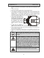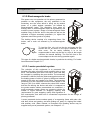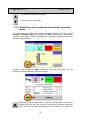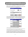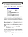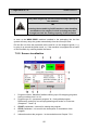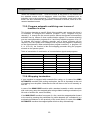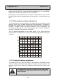
1
Vídeňská 172, Vestec 252 42 Jesenice u Prahy Czech Republic Tel: +420-234 144 746, 710 Fax: +420-234 144 710, 777 WMS PROFI WMS AUTOMATIC Product Specification Operating Instructions Maintenance Pragometal s.r.o. WMS PROFI 2 Pragometal s.r.o. WMS PROFI Table of Contents 1. INTRODUCTION ....................................................................... 4 2. SPECIFICATION, PURPOSE AND USE OF PRODUCT .......... 6 3. SAFETY INSTRUCTIONS ....................................................... 14 4. INSTALLATION ...................................................................... 19 5. TECHNICAL PARAMETERS .................................................. 32 6. EQUIPMENT ........................................................................... 35 7. OBSLUHA ............................................................................... 48 8. TROUBLESHOOTING ............................................................ 99 9. MAINTENANCE AND CLEANING OF THE MACHINE ........ 107 10. WARRANTY ....................................................................... 121 11. SERVICE ............................................................................ 122 3 Pragometal s.r.o. WMS PROFI 1. INTRODUCTION The wrapping machines of range WMS enable a wide variability of equipment and accessories according to the requirements of wrapped goods as well as according to the economic efficiency of machine´s run. They are suitable for fixation of pallet units with a stretch film. The WMS PROFI wrapping machine is intended for operations with high capacity of packing and variable height of products on the pallet. The WMS AUTOMATIC wrapping machine is designed for roller conveyors. It is intended for operations with high capacity of packing. 1.1. Convention The text of the Instructions is written in conventional letters as is this paragraph. Names of push-buttons and control elements are written in BOLD CAPITALS. 1.2. Symbols used In the text the following symbols are used: Danger – Failure to observe these Instructions can cause serious injury or death, or serious damage to the machine. Warning of danger of damaging the machine, or injury to operators or persons present in the vicinity of the machine. Information facilitating use of the machine. 1.3. Warning In this documentation, some information is explained on examples. These examples are illustrative only, values of parameters can differ from those of your machine or from the programs used. The display content of your machine can also visually differ from the display contents in this documentation. The difference is caused both by configuration of your machine – the Instructions are written for a fully equipped machine – and by development of the graphical environment. 4 Pragometal s.r.o. WMS PROFI The manufacturer reserves its right to change the display content; however, these changes have neither any influence on properties and parameters of the wrapping machine nor on its control and behaviour that would be at variance with this documentation – Instructions for Use. These Instructions are written for a wrapping machine with maximum equipment. In the case some of the described accessories are not installed in your machine, ignore their description and control. These Instructions are original Instructions for use pursuant to the Directive EU no. 2006/42/EC and are authorized by the manufacturer. 5 Pragometal s.r.o. WMS PROFI 2. SPECIFICATION, PURPOSE AND USE OF PRODUCT 2.1. Description, Accessories 6 Pragometal s.r.o. 1 WMS PROFI Basic frame with circular turntable. There are fixed a mast with further accessories on the frame. In WMS AUTOMATIC machines there is also the ending mechanism mounted on the frame (see points 5 and 6 further in text). The turntable is rotating on a central bearing and auxiliary rolls. The goods are placed on a turntable available for easier manipulation in executions as follows: basic execution – standard turntable. The diameter is 1500 or 1800 mm (used in WMS PROFI only) turntable with roll conveyor (driven) turntable with chain conveyor (driven). These executions are used for integration in a packing lines with roll event. chain conveyors turntable with gravitation conveyor (non-driven), the conveyor is feeded with the goods manually. Roll conveyor on turntable enables easier handling with the goods (used in WMS PROFI only). forklift-shaped turntable – enables using of low-lift trucks for loading the goods on turntable without using a turntable bridge. The diameter is 1500 or 1800 mm (used in WMS PROFI only) Turntable drive – available types: an electric motor with mechanic gearbox. Transmission of torque is done by a chain strained through a roller. On this execution with an exacter run is the motor with gearbox placed out of the mast. an electric motor with an intergearing by a V-belt. By this intertransmission a power transfer to the required turntable speed is done, it supports the soft start and stop of turntable. The electric motor is put inside the mast. 2 Mast of the machine is fixed to the basic plate by bolts. Its construction is shaped by metal profiles and metal plate or plastic covers. A switchboard and control panel are integrated in the mast. Inside space of the mast contents guiding and traversing slides of film carriage, electric drive of film carriage, switchboard and system of end switchers. Standard heights of masts are 2300 mm 3000 mm 7 Pragometal s.r.o. 3 WMS PROFI Film carriage with prestretch device. Film carriage is constructed by a welded frame with rolls of a travel which is driven by an electric motor via a belt. Respective film holder is created by various optional units of film carriage which are used according to wrapped goods: elektromagnetic film brake – for lower and middle wrapping capacity mechanic prestretch – for middle wrapping capacity with requirement for lower film consumption caused by its stretching through rolls of prestretch device 1-motor driven prestretch – for quality wrapping with zero or occasional requirement for change of value of primary prestretch 2-motors driven prestretch – advantageous in quality and sophisticated wrapping with frequent changes of parameters 4 Top platen of unstable goods. The top platen device does not form a standard machine part. It is advantageous for use in case of light or unstable goods. It is mounted on the mast separately. This equipment is available in executions eletric top platen, pressing power 500 N (50 kg). 5 Ending arm. It is used in WMS AUTOMATIC machines only. It is instrumental for automatic wrapping termination, i.e. for cutting the film off and for welding of lose film end to the pallet. It cooperates with the film fixture. 6 Film fixture. It is used in WMS AUTOMATIC machines only. Its location is on the turntable and it is functional in cooperation with ending arm. In the termination course it catches the film end from the prestretch device and when starting next pallet wrapping the film is fixed to. When the goods are loaded on a standard turntable (not forklift-shaped one) by a pallet truck or by other manipulation means the order can be completed by a turntable bridge which is firmly fixed to the machine base. Its orientation (a direction how to fix it) will be qualified by space and manipulation relations in the workshop. The turntable bridge may be ordered together with a machine or, when necessary, anytime later. Further solution of this requirement would be to use the floor frame. The turntable surface gets on the same level as the floor level is, there is not necessary to pass any vertical interval. The floor frame is supplied by the producer incl. documentation. Building activities (embeding the frame into the floor and its fixation via concreting) are necessary, the machine is consequently put into the fixed frame withou any further mounting or other labours. Floor frame can be installed within machine delivery or anytime later. With a WMS machine placed in the built-in frame must be specially respected the prohibition to drive the fork lift on the turntable surface. 8 Pragometal s.r.o. WMS PROFI If the wrapped goods are to be pressed sufficiently with a heavy pressing power (because of stability or to reduce their volumen) a portal pneumatic top platen able to put on a power up to 13 000 N (up to 1300 kg) is available. Small channels for inserting strapping band when the goods are strapped are situated on the pressing plate of portal pneumatic top platen. In case of demand for automatic top sheet application the top sheet device has to be ordered – see Chapter 6.6 for description and operation. The top sheet device will be installed by its manufacturer or supplying company. A detailled description of single parts of the wrapper incl. attendance and operation can be found in Chapter 5. 2.2. Expendable property The machine is used for stretch film wrapping of the goods on pallets by LLDPE (low linear density polyethylene) stretch film of 20 ÷ 40 μm of the thickness. In the machines provided with mechanical, one-motor or two-motors prestretch device there must be used a stretch film of minimum stretching limit of 150%. The equipments as electromagnetic brake do not need any guaranteed stretching limit. The stretch film must be available in the form of rolls of 500±10 mm of the width and max. 250 mm of the diameter. The core on which is the film wrapped must be of inside diameter 76±3 mm and 510±5 mm of the length. A cling stretch film as well as one-side-cling film can be used. The adhesive power of one side means the particular film layers wrapped on the goods cling each other perfectly and they do not have any habit to damage the goods on the pallet any way. The main purposes for using this film are the better goods fixation to the pallet, the higher packing rigidity and its better weather effects and mechanical strain resistance within transport. When wrapping the pallets with the goods the stretch film has to be orientated „inside cling“, i.e. the cling side to the goods. When handling the pallets afterwards or transporting them there is no pallets tendency to adhere to each other. The film is standardly 6 months UV resistant, i.e. the wrapped goods may be outdoor stored and exposed to the sun radiation for 6 months without any damage while all the original wrapping characteristics are kept. In case of requirement for longer outdoor conditions storage are to be used the stretch films with increased UV resistance. Following stretch film grades meet the above mentioned requirements: Type POWERFLEX SQ Stretch Grade 160% Application Executions Available Electromagnetic stretch film brake. Various thicknesses Wrapping of heavy goods with sharp edges. Non-cling and one-side-cling 9 With increased UV resistance Pragometal s.r.o. Type POWERFLEX PQ POWERFLEX HPQ POWERFLEX SPQ Stretch Grade 200% 250% 300% WMS PROFI Application Executions Available Mechanical, one-motor or two-motors prestretch devices. Various thicknesses Wrapping of medium-heavy or light goods, or wrapping of fragile or deformable goods. With increased UV resistance Automatic machines with mechanical, one-motor or two-motors prestretch devices. Various thicknesses Non-cling and one-side-cling Non-cling and one-side-cling Similar application as on PQ. With increased UV resistance Similar application as on HPQ. Various thicknesses Non-cling and one-side-cling With increased UV resistance When putting the wrapping machine into operation it is recommended to contact the machine supplier or producer who is able based on experience to recommend an optimal stretch film grade for wrapping of the appropriate goods. Any other kind of packing materials (e.g. perforated films, net ones, sandwich films, printed ones, bubble films, etc.) as mentioned above cannot be recommended to be used without previous consultation with the machine producer and without his approval – a propper machine operation cannot be guaranteed otherwise. In case the wrapping machine does not wrap a correct way during warranty time or if it is damaged or the wrapped goods injured a claim can be refused by the producer in case some non-approved packing materials or films have been used on the machine. 2.2.1.Ecology The films can be classified as the plastic material (more precisely in the PE polyethylene class) in the sorted waste. It is well-recyclable. It can be successfully combusted and there do not appear any harmful combustion gases under corresponding combustion conditions. The PE polyethylene is not biologically decomposable and its degradation in the dumping ground takes rather long time. No dangerous products escaping to the air or contaminating water or earth are known. 2.3. Machine Performance The performance satisfies the technical standards and regulations provided under the Letter of Conformity which is a part of this accompanying technical documentation. The relevant norms and regulations are included in production documentation. Measures taken from the part of producer are described in this accompanying technical documentation, in this Manual. 10 Pragometal s.r.o. WMS PROFI The estimated lifetime of a machine is 50 000 hours as long as it is used in compliance with this accompanying technical documentation, required maintainance is provided, and periodic checks are performed. 2.4. Operating Conditions The wrapping machine is designed for operations meeting following conditions: Normal environment AA5+AB5, as per IEC 364-3:1993 by the terms set forth in this Chapter, and installation and operating guidelines based on this accompanying technical documentation. The machine will be installed and operated in sheltered workshops protected against weather effects. There must be a flat and reinforced floor, maximum allowed deviation from floor flatness is ±3 mm/2m. Before setting the machine on a place, rough impurities, small stones, etc. must be deprived. The range of temperatures for operating the machine is +5 up to +40 ºC, the changes of temperture must not be more frequent as 10°C / 30 min. Relative moisture 30 ÷ 95% without condensing moisture (dew). The machine and primarily its electrical devices shall be installed and operated in compliance with the manufacturer instructions provided in the accompanying technical documentation. The machine shall be operated in sufficiently lit working areas satisfying national regulations for working environment. It is prohibited to place the machine the way which would minimize the width of access pathes to an electric installations under minimum values given in national regulations. There must not be placed any retardation which maight cause an injury of operator closer to the machine (stairs, ramps, lowered ceilings, other machines, etc.) The operation of the product shall be prohibited in an explosive environment or in that one where conditions to explosion would appear even for a short while. The machine and primarily its electrical devices shall be installed and operated in compliance with the manufacturer instructions provided in the accompanying technical documentation. 11 Pragometal s.r.o. WMS PROFI 2.5. Safety space A minimum space around the machine has to be reserved to keep the operating personnel save. It is prohibited to place any objects to this area, an other machine or the operating area of an other machine is not allowed to interfere in. The minimum area diagram does not approve this area as considered even for bringing the goods in or carrying them away. 1000 1) 1300 2) 250 600 0 60 500 Dimension 1) is valid for a machine provided with a prestretch device without tipping cover of rolls space (i.e. for manual film brake, mechanical prestretch device, electromagnetic brake or one-motor prestretch LIGHT); Dimension 2) is valid for a machine provided with a prestretch device with tipping cover of rolls space (i.e. for one-motor and two-motors prestretch devices). Which type of prestretch device has been mounted to your machine can easily be found in the available commercial documentation, or you can find the description of prestretch devices incl. their drawings in the Chapter 6.3. 2.6. Operation The machine shall be operated by a single person. The control board workstation will make sure the operator is out of the operating space of the machine. 12 Pragometal s.r.o. WMS PROFI 2.7. Electric Outfit of the Machine The electric outfit of the machine complies with the EN 60204-1 standard. The machine is shielded in compliance with Group 1, class B. according to the standard EN 55011. From the point of view of jamming the machine conforms to the requirements of standards IEC 1000-4-2, EN 61000-4-2 IEC 1000-4-3, EN 61000-4-3 IEC 1000-4-4, EN 61000-4-4 IEC 1000-4-6, EN 61000-4-6 The electric outfit of the machine consists of a switchboard and the electric wiring in the machine. The switchboard includes a 5-pole line terminal block and a main switch of the whole machine.The power supply shall be protected using fuses or breakers. The grid in the place of connecting the machine has to be in conformity with international as well as national regulations and standards. 13 Pragometal s.r.o. WMS PROFI 3. SAFETY INSTRUCTIONS 3.1. Revisions and tests of electric outfit The machine is subject to periodic revisions and tests of electric outfit. Along that the conditions of EN 60204-1 have to be met. Before putting the machine in operation the revision of electric equipment must be carried out – see Chapter 3.3. 3.2. Safety Recommendations Whereas any unprofessional handling of the electrical devices within the machine might cause severe damages to the machine, or even injury of the operator, each operation may only be completed by a trained and authorized person as per the national guidelines for work on the electrical equipment. The persons operating wrapping machine must be familiarized with this Manual by the way which is possible to demonstrate and this Manual has to be for stable disposal of operators.. The main switch on the switchboard may be locked in the OFF position. We recommend the user of the machine to address administration of the key to this lock within the operation where the wrapping machine is to be installed, thus preventing any unauthorized person, not familiar with the operation, to start up the machine. 3.3. Work Safety 3.3.1.Safety devices to ensure work safety The wrapping machine has a simple frame without any occurence of hazardeous points which might jeopardize health of the operator within operation if the specified wrapping procedure is followed. Hazardeous points in working space result from the principle of machine operation: 1) Turntable rotates together with a pallet placed on. The rotating section of the machine with a pallet is not protected using special covers since this would disable the actual process. 2) Film is led through the rolls of prestretch device. 3) Film is rolled on the wrapped goods and tighten on with certain power. 4) An electrostatic charge may arise on the film. 5) Film carriage drives all over the height of the mast down to the floor. 14 Pragometal s.r.o. WMS PROFI 6) Top platen, when used, presses the pallet with a pressing power of 500 N (50 kg) in case of electric or pneumatic execution, when a portal top platen is used the value of pressing power comes up to 13 000 N (1300 kg). 7) Roll or chain conveyors, when used, allow an autonomous movement of pallets loaded with the goods. 8) In WMS AUTOMATIC machines there is used the ending mechanism for the film separation by heat and its welding – the separation string and welding bodies are hot. 9) In WMS AUTOMATIC machines the ending mechanism with film catcher for the film fixture is used. The mechanism is located on the turntable. The gripping force effecting on the film represents 22 kg as maximum. To protect the opeator there are used on the machine: 1) Pushbutton TOTAL STOP for immediate outage of device. Pushbutton is blocked mechanicaly in off position and it is located on the control board within reach of the operator. 2) Pushbutton CONTROL VOLTAGE. Within outage of feeding or within pushing pushbutton TOTAL STOP will be pushed the supply of control system is disconnected and the machine disabled, even when the feeding is reset or even when incidentally or by mistake of operators or during maintenance pushbutton TOTAL STOP is prematurely deblocked. Only pushing of pushbutton CONTROL VOLTAGE enables to put the machine in operation again. 3) The machine is controlled via a control board which is located on the sidewall of the machine to be out of the operating space. 4) A protective deflective frame to stop the descending film carriage from moving. It is located in the lower part of the supporting carriage frame. 5) In 1- and 2-motors driven prestretch equipments is the space of prestretching rolls fully covered by tipping cover. Its opening (tipping out) stops and block the machine operation. 6) The machine is blocked by a sensor in case of pallet truck presence within loading or unloading the pallet in the cut-out area of a machine provided with forklift-shaped turntable. 7) A pressure plate of top platen unit for unstable products can be regulated not to exceed 500 N and jeopardize the operator by pressure. 8) Rotating parts of transmission devices are fixed inside the machine frame. 9) The ending mechanism in the WMS AUTOMATIC machines: in the course of wraping action the ending mechanism hot parts are covered in idle and they are not heated. They are released and heated just for the must time for film heat separation and its welding operation. 10) The ending mechanism in the WMS AUTOMATIC machines: Control element (controller) for the film fixture opening and closing is located on the place prohibiting the operating personnel to reach the film fixture mechanism during operation. 15 Pragometal s.r.o. WMS PROFI 3.3.2.Operator and user obligations For personal safety are the operators obliged to keep the directions as follows: 1) The machine may only be operated by a single person. Apart from the operator, no other people are allowed to stay nearby the machine under operation. 2) The machine may only be operated when the operator keeps permanently out of operating space of the machine (i.e. at control panel). 3) The wrapping machine may only be operated by a specified/determined person older than 18 years of age only, who is properly instructed and familiar with these instructions as well as safety rules. 4) No spirit consumation, use of addicting substances or medicines influencing the work safety is allowed by the staff. 5) The operators are obliged to operate and maintain the machine in accordance with this Manual. When using the machine a correct way material damages or injuries may be eliminated. 6) Prior to start working, the operator shall check on the overall condition of the machine and proper functionality of the individual parts. In particular, integrity of electrical cables. For the whole period of operation, he/she should keep the work place and its immediate surroundings clean. 7) Changing of film roll or any other manipulation with prestretch equipment may only be done when the machine is disabled. 8) The operator will handle pallets on the turntable so that no of its parts overlap the turntable profile. The pallet shall not be positioned on the turntable eccentrically. 9) In case of handling a loaded pallet on a roll or chain conveyor any further handling with wrapped goods or with a conveyor under machine or conveyor operation an other way as decribed in this Manual is prohibited. 10) Covers may only be removed, dismounted, or lifted when the machine stops fully, and the shutdown condition is secured. 11) Rotating machine parts shall perform in a direction of the attached arrow. 12) Safety marks, symbols, and machine labels shall be legible. If they are damaged or unlegible, the user shall reinstate the original appearance. 16 Pragometal s.r.o. WMS PROFI It is restricted to: 1) Use the machine an other way or for other purposes than mentioned in this Manual. 2) Start up and use the machine if the protection device (covers, keyboard foil cover) are removed or damaged. 3) Touch the moving machine parts, rotating pallet or rolled-on film. 4) Manipulate in the space of prestretch rolls within rotating turntable. 5) Pass through or manipulate any way in the space between the mast and the turntable. 6) Enter a rotating turntable. 7) Manipulate the goods when top platen has been activated. 8) Operate the machine if there is not enough light in the working space and at the workshop. 9) Maintain, clean, or repair the machine under operation, or unsecured against inadvertent actuation. 10) Check and repair the electric device with a person who is not fully skilled. 11) Inactivate safety, protective and protecting device or intervene any way construction and electric elements of the machine. 17 Pragometal s.r.o. WMS PROFI 3.4. Work Hygiene The mass of the packaging foil is equal to about 17 kg. All women and youth are forbidden to handle loads over 15 kg. The character of produced and packed goods influences the working environment, in which the machine is being used. Its manager is obliged to ensure safety at work and of workers’ health in conformance with national regulations for the protection of health. For handling of wrapped pallets, the operator shall use mechanical lifting devices, provided by the employer, to reduce physical efforts. If the nature of wrapped products is such that the operator’s hands or other body parts might get injured while manually handled, or that the wrapped goods do not meet hygienic limits (chemical materials, dustiness, noise, etc.) the operator shall wear protective clothing to be provided by the machine owner. There is in the place of operator 63.9 dB of equivalent level of acustic pressure meassured by function A within the time of wrapping cycle. The machine itself meets sanitary limits. Noise precautions are dependent on a specific workstation, and they follow the national health protection regulations. 3.5. Fire Protection The user shall provide appropriate fire protection devices to ensure fire safety at the workstation when the wrapping machine is under operation. Their specification and location shall be consulted and approved by the supervisor and fire protection experts, primarily in respect to the nature of processed materials as well as to the classification of wrapping machine as an electric device. The location and types of extinguishers shall be determined by a fire protection engineer, employed by the user, based on local conditions. 3.5.1.Instructions for operators In case of fire, the operator shall first disconnect the power by unplugging the machine, or releasing the main switch. The operator shall only use the specified extinguishers to put down the fire. Fire extinguishing either with water or foam extinguisher is prohibited ! 18 Pragometal s.r.o. WMS PROFI 4. INSTALLATION This chapter concerns the storage, installation and putting the WMS wrapping machine in operation. The information concerning any further handling with already operated machine is also included. 4.1. Storage If the machine is not put in operation immediately following its delivery it is necessary to store it in the original protective packing on a sheltered place protected against atmospheric effects. The storage temperature range moves between 0ºC and +55ºC, allowed humidity from 5% till 95% without condensation (dew). In the storage place there must not be stored any corrosive matters, or the matters releasing evaporations able to damage the electric wiring insulation, or substances creating fire-hazarding or explosive environment. 4.2. Project At the WMS machines built-in to the lines with roll or chain conveyors a project must be worked out prior to the installation; such a project has to solve: • performance of machine working milieu requirements (see the Chapter 1.4); • operating personnel safety as well as the safety of further persons present closely to the machine working area. It is necessary to prohibit the access in the machine working area within the wrapping operation, or more precisely, putting the machine into operation when there is a person present. For these purposes they are intended the safety lock and additional safety means, if necessary (lighting blocks, door electronic locks, etc.); • the machine location and orientation within the frame of a packing line with respect to the machine as well as the line functionality and with respect to the wrapped goods characteristics; • location of the switchboard and location of the operating personnel position (in case the machine has been supplied without switchboard or with a separated switchboard); • access to the attendance stations and to the stations necessary for service and maintenance operations; • mechanical, electrical and program interactions with other machines installed in a line; • electrical energy and compressed air supply, and the cabling guiding must be done a way protecting both an eventual supplies and leading wires against the damage and the injury of the operating personnel and other persons present close to the working area; • installation of additional Emergency-Stop push-buttons, if necessary, to be easily accessible both for the operating personnel and for other persons which could be present in the working area neighbourhood. 19 Pragometal s.r.o. WMS PROFI The project is allowed to be worked out by a company or by a person which is cognizant of working and machines safety principles included in the valid international as well as national standards and regulations. The safety factors of the complete working area have to be analysed by the project supplier which is responsible for the offered solution and has to work out also the working safety guidelines, if necessary. Standardly would the project be worked out by the producer or by the machine supplier. The machine corresponds to the standards and regulations valid in the European Community countries under condition that the project has been worked out to meet the requirements stated in this Chapter and valid for the concrete working area. The project would also be worked out for the machines buit-in to the embedded floor frame. The reason for that will be found in the subsequent difficult replacing the machine and the frame embedded in concrete. The project in question can be worked out in a simplified form showing a solution of wrapping machine location with respect to: • the operating personnel safety as well as the safety of other persons present closely to the working area; • the access of handling facilities to the wrapping machine enabling an easy supply of the goods to be wrapped on turntable and the transport of the goods already wrapped out of the machine wrapping area. 4.3. Assembly, handling The machine handling is allowed via a lift truck, necessary fork dimensions and load capacity are always mentioned in the appropriate article. Any handling via pallet truck or a cran is prohibited on all of the machine models. It is also prohibited to handle the machine with a pallet loaded with goods. When an extreme temperature difference appears during the transport to the destination it is necessary to wait an adequate long time until the machine and exterior temperatures are not equalized – condensation (dew) danger. The machines are, exept those ones provided with a conveyor on turntable, supplied with the tilted mast which has to be erected when putting the machine into operation. !!! WARNING !!! Working methodes as well as instructions stated further in the text must ALWAYS be kept when erecting or tilting the mast. Handling with mast without using the manipulation tool is NEVER allowed. Erected and to the turntable not yet fixed mast remains unstable. There is high danger of workers injury and machine damage due to the mast weight! The machine shall never be lifted at the turntable. 20 Pragometal s.r.o. WMS PROFI 4.3.1. Standard PROFI models This concerns the standard execution the machines with standard turntable and without any roll or chain driven conveyors on turntable or without a gravitation conveyor on turntable. The machine is delivered with the tipped mast. For manipulation with the machine there are ports for the skids of the high-lift truck in the carrying section, with dimensions of max. 130×40 mm, satisfying ISO 2328 – these ports are marked with the arrows in the picture. The loading limit of high-lift truck must be min. 1500 kg. Put the machine in the place, where it will be used and put it into operation there. We do not recommend manipulation with operated machine – see below in this chapter. The machine workplace must satisfy the conditions stated in chapter 2.4. The material mentioned below in the text, which is necessary for putting the machine into operation, is installed in the places, where it will be used later. Follow these instructions during putting into operation: • Remove the protective wrappings • The mast is tipped in the manipulation preparation; this preparation is created by the hinge join, around which the mast turns over when erecting. For transport, the manipulation preparation with mast is installed in the transport position and so it is necessary to shift it into the working position. In the place for working position, there are prepared ports with screws on the turntable, for installation of the manipulation preparation with mast. Transport position and shift to the working position (dashed line) is illustrated in the picture: 21 Pragometal s.r.o. WMS PROFI Take out the screws fixing the preparation to the turntable (in the picture marked with Ì), shift the mast including the preparation and prestretch device to the fixing ports in the working position according to the turntable model and screw down the preparation with the mast in this place again to the turntable. The mast weight is from 160 kg for the simplest model up to 270 kg for maximal equipment. 1 • Take down the front cover of the bottom mast part pos. 1. Dismount the rear cover pos. 2. • Erect the mast (take care so that cabling is not damaged) and screw it to the basement in places pos. 3 – the following is delivered: 4 pc screws 3 M10×20, washers 10.5 and lock washers 10. According to the user’s choice, the manipulation preparation may be kept installed on the turntable and mast (recommended) or dismounted; 2 functions, parameters of the machine or work safety are not affected in any way. • Fix the covers back. • Remove the wooden support joist on the prestretch device. • If the machine with top-platen is delivered from production, its jib is dismounted. The assembly of the jib with the top-platen rests in its screwing down to the truck of the top-platen with delivered connection accessories (2 pc of nut M12, washer 13, Lock washer 12 ). • In case that the machine is equipped with pneumatic top-platen, connect it to the source of compressed air. • Finally, check the power supply and connect the machine to the network in the way according to chapter 4.5. Keep all parts and connection accessories dismounted during putting machine into operation, for the case of later transport. 22 Pragometal s.r.o. WMS PROFI For short distances (c. meters, only corrections of placement in the workplace) the machine may be carefully shifted in the erected position on the braced surface without unevenness and super elevation; as for the high-lift truck, the provisions from the introduction of this chapter are valid. By default, it is necessary to transport the machine in the tipped position, in which it was delivered! Act as follows during preparing for transport (positions and marking refer to the pictures in the part putting into operation): • Before preparing for transport the machine is functioning and connected to the network, or to source of the compressed air (if the machine is equipped with the pneumatic top-platen). • Install the support joist on the prestretch device. For its installation, there is prepared screw M8 on the prestretch device on the right side (towards turntable), install the joist in the horizontal position so that it support the prestretch device and the mast after tipping. • Set the prestretch device by the manipulation in manual mode (see chapter 7.9) in such height that the lower edge of the support joist is (1150±20) mm away from the lower edge of the mast. If the machine is equipped with the pneumatic top-platen, descend it into the bottom position. • If the manipulation preparation was dismounted after the installation, it must be re-mounted on the mast and turntable again. 1150 • Switch the machine off and disconnect it from the network by unplugging of the plug from the socket. If it is equipped with pneumatic top-platen, disconnect it from the source of compressed air. • If the top-platen is installed on the machine, dismount the jib of the top-platen with the top-platen desk – 2× nut M12 with washers. Keep the connection accessories for the follow-up mounting. • Take down the cover of the bottom mast part pos. 1. Dismount the rear cover pos. 2: screw out four screws M5 and take down or push up the cover so that the screws fixing the mast to the turntable are accessible. • Loosen the mast from the turntable – screw out in the places pos. 3 - 4 pc screws M10×20, washers 10.5 and lock washers 10. Keep the connection accessories for the follow-up mounting. • Fix the covers back. • Tip the mast, take off the screws fixing the manipulation preparation to the turntable and shift the manipulation preparation with mast and with the prestretch device into the transport position (instead of transport position see the mounting description in this chapter) – take care so that the cabling is not damaged – and fix the transport preparation in this place to the turntable. 23 Pragometal s.r.o. WMS PROFI After shifting, the assembly is the same as the procedure of putting the new machine into operation in the introduction of this chapter, including the check-up of power supply according to chapter 4.5, especially in case of connection of the machine in other socket than before. 4.3.2. Execution with the conveyor on the turntable This concerns the execution with roll or chain driven conveyor on the turntable or with the gravitation conveyor on the turntable. The machines are to be fixed at the concrete place according to the project. The assembly as well as the installation is standardly done by supplying company (a correct mechanical and electrical connection to the transport conveyors has to be secured). The machines already assembled cannot be handled, any more. These models are standardly supplied in partially disassembled state, the turntable and the mast separately. Should a machine be provided with top platen, its arm with the pressing plate will be separated, as well. The mast and, eventually, the top platen arm with pressing plate are placed on the pallets. ! ! Handling with still packed turntable will be allowed via lift trucks with 1200 mm long forks of max. dimensions 130×50 mm, meeting standards ISO 2328, or with pallet trucks, their min. load capacity is 1500 kg for turntable with diameter 1500 or 1800 mm, or 2500 kg for turntable with diameter 2300 mm. There are handling holes in supporting profiles under the turntable for application of lift truck forks – these holes are marked with arrows. When forks are longer as recommended take care they do not collide with a turntable weldment on the mast side (see drawing). The other machine parts are supplied separately on a pallet. When the handling ways of various machine types differ, the distinct and complete information how to manipulate them are put directly on the machines transport covers. 4.3.3.Execution with the forklift-shaped turntable This concerns the execution with forklift-shaped turntable. The following serves for manipulation with the machine: • ports for the skids of the high-lift truck in the carrying section under the turntable, their depths are 170 mm 24 Pragometal s.r.o. WMS PROFI (the shortest side of the section). Skids of the high-lift truck insert in these ports during transport • footings fixed on the turntable. They lean on the skids of the high-lift truck from below during manipulation. The skids must have dimensions of max. 100×50 mm and length of 1000 mm and must satisfy ISO 2328. Spacing of the internal edges of skids is 720 mm. Loading limit of the high-lift truck must be min. 1500 kg. Manipulation ports and footings serves only for manipulation with the machine in tipped (transport) state, during putting into operation for eventual lift of the machine. After setting of the machine in the place, it is necessary to remove the manipulation footings (by removal of the cotters in the internal side of the section and release of the footing from the port) – when the footings are kept there, there is a risk of fall. Keep the dismounted footings with cotters for the eventual later use. 4.3.4. Model with Forklift-Shaped Turntable with Diameter of 1800 mm and More - Manipulation The machine is delivered underlaid by transport joists for easier manipulation by the high-lift truck. The truck skids insert in sideways – see light arrows in the picture – and they must have length of min. 1500 mm. Recommended loading limit of the truck is min. 1000 kg. Also there are manipulation ports and footings – but they serve only for manipulation with the machine during removal of the transport joists. 25 Pragometal s.r.o. WMS PROFI Manipulation ports and footings serve only for lift of the machine during inserting or removing the transport joists. It is forbidden to transfer the machine or manipulate with it otherwise by the help of manipulation ports and footings! After setting of the machine in the place, it is necessary to remove the manipulation footings (by removal of the cotters in the internal side of the section and release of the footing from the port) – when the footings are kept there, there is a risk of trip and fall. Keep the dismounted footings with cotters for the eventual later use. 4.3.5. Model with Forklift-Shaped Turntable with Diameter of 1500 mm, 1800 mm and More – Putting into Operation Putting into operation is similar for all diameters of forklift-shaped turntables; therefore the following procedure is common for all models. Possible differences are marked directly in the text. • Put the machine in the place, where it will be used and put it into operation there, the machine workplace must satisfy the conditions stated in chapters 2.4 and 2.5. We do not recommend manipulation with operated machine – see below in this chapter. The material mentioned below in the text, which is necessary for putting the machine into operation, is installed in the places, where it will be used later. • Remove the protective wrappings • The mast is tipped in the manipulation preparation, this preparation is created by the hinge join, around which the mast turns over when erecting. For transport, the manipulation preparation with mast is installed in the transport position and so it is necessary to shift it into the working position; in the place for working position, there are prepared ports with screws on the turntable, for installation of the manipulation preparation with mast. Take out the screws fixing the preparation to the turntable (in the picture marked with ), shift the mast including the preparation and prestretch device to the working position (in the picture marked with dark arrow) and fasten preparation with the mast in this place again to the turntable. The mast weight 2 is from 160 kg for the simplest model up to 270 kg for mast with maximal equipment. • Take down the front cover of the bottom mast part pos. 2. Dismount the rear cover pos. 3: screw out four screws M5 and take the cover off. 4 • Erect the mast (take care so that cabling is not damaged) and screw it to the basement in places pos. 4 -the following is delivered: 4 pc screws M10×20, washers 10.5 and lock washers 10. According to the user’s choice, the manipulation 3 preparation may be kept installed on the turntable and mast (recommended) or dismounted; 26 Pragometal s.r.o. WMS PROFI functions, parameters of the machine or work safety are not affected in any way. • Fix the covers back. • Remove the wooden support joist on the prestretch device. • If the machine is delivered on the transport joists: screw out and take off the cover between the turntable and the mast. Take out the screws fixing the transport joists – in the picture marked with Ì. Lift the machine using manipulation ports and footings and remove the transport joists. Put the machine on the ground again. Do not move the machine in any case! • If the machine with top-platen is delivered from production, its jib is dismounted. The assembly of the jib with the top-platen rests in its screwing down to the truck of the top-platen with delivered connection accessories (2 pc of nut M12, washer 13, lock washer 12). • In case that the machine is equipped with pneumatic topplaten, connect it to the source of compressed air. • Finally, check the power supply and connect the machine in the network in the way according to chapter 4.5. • Remove the manipulation footings fixed on the turntable (by removal of the cotters in the internal side of the section and release of the footing from the port). Keep all parts and connection accessories dismounted during putting machine into operation, for the case of later transport. For short distances (c. meters, only corrections of placement in the workplace) the machine may be carefully shifted in the erected position on the braced surface without unevenness and super elevation, if it is placed on two pallets and the skids of the high-lift truck load it in the sideways. As for the high-lift truck, the provisions from chapter 4.3.1 or 4.3.4 are valid. Use the footings and manipulation ports for lift of the machine so that it would be possible to lay the pallets under the machine. By default, it is necessary to transport the machine in the tipped position, in which it was delivered. It is forbidden to transport the machine in the erected state using footing and manipulation ports in the turntable! 27 Pragometal s.r.o. WMS PROFI Act as follows during preparing for transport (positions and marking refer to the pictures in the part putting into operation): • Before preparing for transport the machine is functioning and connected to the network, or to source of the compressed air (if the machine is equipped with the pneumatic top-platen). • Set the prestretch device by the manipulation in manual mode (see chapter 7.9) in such height that the lower edge of the support joist is (1150±20) mm away from the lower edge of the mast. If the machine is equipped with the pneumatic top-platen, descend it into the bottom position 1150 • Install the support joist on the prestretch device. For its installation, there is prepared screw M8 on the prestretch device on the right side (towards turntable), install the joist in the horizontal position so that it support the prestretch device and the mast after tipping. • Switch the machine off and disconnect it from the network by unplugging of the plug from the socket. If it is equipped with pneumatic top-platen, disconnect it from the source of compressed air. • Mount the manipulation footings on. • If the top-platen is installed on the machine, dismount the jib of the top-platen with the top-platen desk – 2× nut M12 with washers. Keep the connection accessories for the follow-up mounting. • If the machine was delivered on the transport joists (the transport joists are always used for turntables with diameter of 1800 mm and more), dismount the cover between the turntable and the mast, lift the machine by the help of highlift truck and insert the joists under the machine – do not traverse the machine! Use the joists delivered with the machine or wooden joists 100x100 mm with length of 1920 mm. Screw the transport joists to the machine with wood screws 8x50 – placement of joists and wood screws is illustrated in the picture in the part Putting into operation. Mount the cover back. • Take down the cover of the bottom mast part pos. 2 2. Dismount the rear cover pos. 3: screw out four screws M5 and take down or push up the cover so that the screws fixing the mast to the turntable are accessible. 4 • Loosen the mast from the turntable – screw out in the places pos. 4 -4 pc screws M10×20, washers 10.5 and lock washers 10. Keep the connection accessories for the follow-up mounting. 3 • Fix the covers back. • Tip the mast, take off the screws fixing the manipulation preparation to the turntable and shift the manipulation preparation with mast and with the prestretch device into the transport position (instead of transport position see the mounting description in this chapter) – 28 Pragometal s.r.o. WMS PROFI take care so that the cabling is not damaged – and fix the transport preparation in this place to the turntable. For shifting, the assembly is the same as the procedure of putting the new machine into operation in the introduction of this chapter, including the check-up of power supply according to chapter 4.5, especially in case of connection of the machine in other socket than before. 4.4. Assembly of portal top platen Separate manual for assembly, putting into operation and control of the equipment is delivered with the portal top-platen. We warn that portal top-platen is able to put on the variable adherence pressure of max. 1300 kg. Summation of this adherence pressure and weight of the pallet must not exceed the loading limit of the turntable; otherwise there is a risk of turntable damage. 4.5. Network Connection At first, check the operational voltage and frequency stated in the plate of the electric equipment, if they correspond to voltage and frequency of the electrical network, to which it should be connected. Distribution of the electrical network and connection of the sockets have to correspond to the valid international and national regulations and standards. Voltage fluctuation of max. ±5% of the nominal value still secures the correct machine function. The connection of the machine is realized via cable ended with plug CVG 1643, which is connected to the terminals U,V,W,N,Pe in the switchboard. The supply cable must be led so that the manipulation or transport technology does not drive over it and so that it is not a source of injuries. 29 Pragometal s.r.o. WMS PROFI Check the connectors on cables connecting the turntable with the mast, which are placed in the bottom mast part. The connectors are already combined from the production for standard machines delivered with the mast, which is mounted on the turntable and tipped. The connectors may be disconnected for the machines with separate or separately delivered mast because of easier manipulation and transport. It is necessary to connect them according to the description on the right side in the picture Remove the protective label from the main switch after careful check of the service line and connectors. After that it is possible to insert the plug into the socket and connect the machine to the network by the main switch. Check the phase-matching of the machine. Carry out this check-up always when the machine is connected to other socket than before. The machine turntable, prestretch device and top-platen must move in the correct direction according to the arrows on the control panel. Caution – check the drive, where the frequency convertor of revolutions is not included. You must disconnect the electrical power supply to the machine by switching-off the main switch and unplugging of the plug from the socket, when re-phasing the machine. Only person competent in the terms of chapter 3.2 may carry out the re-phasing of the machine. If the stretching device of the machine with connected input phases reaches the end-limit switch, the display will show error message Errv. In such case, first connect the machine to phases and then reset the error message using the procedure given in chapter 8. External protective terminals on the machine and contactor switchboard must be connected by the user to the user’s protective system and they have to be conserved properly. The initial revision of the electric equipment must be realized before putting into operation – see chapter 3.2. 30 Pragometal s.r.o. WMS PROFI 4.6. Machine connection to the compressed air When the machine is provided with a pneumatic device (i.e. it is provided with ending device or pneumtic top platen) it must be conntected to the compressed air supply. See the Chapter 4 for its parameters. 4.7. Dismounting the machine Before liquidation of the machine after the end of its technical life put all mechanisms in such positions, that there is no danger that dismantled machine parts will fall from elevated positions and to enable dismantled parts to be taken away safely. Disconnect the supply of electric energy by disconnecting the plug from the socket. A person qualified according to Chapter 3.2 will check the electric circuit for the presence of residual voltage; if such a voltage is present, it has to be discharged. Dismantle motors with gearboxes, drain off oil from them and store it in safe, unbreakable and tight vessels. Dismount all the machine parts. All the parts will be sorted according to the waste clasification (steel, non-ferous metals, plastics, cables, electrical elements, etc.). Thus assorted waste incl. lubricants will be handed over to the specialized companies to a professional liquidation. 31 Pragometal s.r.o. WMS PROFI 5. TECHNICAL PARAMETERS WMS PROFI Executions turntable 1500, 1800 mm, basic 2300 basic 1500, 1800 mm, basic 1500, 1800 mm, forklift conveyor Weight none yes 600 kg 600 kg (as per equipment, min.) Dimensions (see production plate) height 2366 mm (3366 mm) width length Turntable diameter loading limit drive revolutions 2300 mm 1500 (1800) mm 1) 2350(2650) mm 3150 mm 2350 (2650) mm 2) 1500(1800) mm 2300 mm By coveyor width 1200 kg 1500 kg 1500 kg 1500(1800) mm 1) el. motor 550W / 50Hz 400 V 10 rpm + 20% 750W / 50Hz 400 V 7 rpm + 20% sense of rotation 10 rpm + 20% right Film carriage drive el. motor 180W / 50Hz 400 V Top platen carriage drive el. motor 120W / 50Hz 400 V Air pressure max. 1.5 MPa 4) Input 0.5 MPa 4) Working Weight of film roll Roll width conveyor Electric installation parameters ca. 17 kg Roll conv.: 900,1100,1300 3) --- Chain conv.: 700, 1000 3) height --- 460 ± 40 mm speed ----- 0.2 m/s el. motor 550W/50Hz 400V drive Operation voltage Machine input 3 × 400 V / 50Hz 1.5 … 3.5 kVA (see production plate) Mains protection 10 … 16 A (see production plate) Control circuit voltage Electric device protection class 24 V IP 54 1) Machine width is identical to turntable diameter Length without coveyor 3) Based on purchase order 4) Only when portal top platen is used. 2) 32 Pragometal s.r.o. WMS PROFI WMS AUTOMATIC Executions turntable Automatic 1500, 1800 mm conveyor yes Weight 800 kg (as per equipment, min.) Dimensions height (see production plate) min. 2590 mm (mast 2300); 3290 mm (mast 3000) width min. 1670 mm 1) length 2435 mm 1) Turntable loading limit 1500 kg drive 750W / 50Hz 400 V revolutions 10 rpm + 20% sense of rotation right Film carriage drive el. motor 180W / 50Hz 400 V Top platen carriage drive el. motor 120W / 50Hz 400 V Air pressure Input max. 1.5 Mpa Working 0.5 MPa Weight of film roll ca. 17 kg Roll width conveyor Roll conveyor: 900, 1100, 1300 2) Electric installation parameters 1) 2) Chain conveyor: 700, 1000 2) height min. 350 mm speed 0.2 m/s drive Operation voltage Machine input el. motor 550W/50Hz 400V 3 × 400 V / 50Hz 1.5 … 3.5 kVA (see production plate) Mains protection 10 … 16 A (see production plate) Control circuit voltage Electric device protection class 24 V IP 54 Diameter by conveyor; table parameters valid for roll conveyor 900 Based on purchase order 33 Pragometal s.r.o. WMS PROFI 5.1. Production Plate Type plate is placed in the mast bottom part, its identical copy is protected against damage inside the switchboard. Contents following data: supplier´s name and address type description of product serial number of machine vintage of machine wiring diagram No. weigt (kg) supply voltage (V) frequency of supply voltage (Hz) protection (A) input of machine (kVA) voltage of control circuit (V) The data given on production plate are to be prefered prior to those ones given in charts of technical parameters or other ones given in this accompanying documentation. 34 Pragometal s.r.o. WMS PROFI 6. EQUIPMENT 6.1. Turntable Machines WMS PROFI can be equipped with the turntable: Standard. Manipulation with the pallets is by the help of high-lift trucks, it is possible to use even low-lift trucks after adding of drive-up ramp. If requested, it is possible to deliver the turntable with plangette for locking of the film before start of the wrapping; it is possible to mount it on even additionally. The standard turntable has diameter of 1500, 1650, 1800 or 2300 mm. With roll or chain track. This model is designed for the wrapping lines. According to solution of your workplace, the goods either comes automatically, or it is called by the button PALLET FETCH and after warpping it is sent further on the track by the additional button PALLET SENDING. With gravity roll track. This is also designed for wrapping lines. The track is not driven on the turntable, the goods have to be carried on the track and carried away manually by the staff. The rolls make manipulation on the track easier. Forklift-shaped, which makes the loading of pallets to the wrapping machine easier by the help of low-lift manipulation trucks without the necessity of using the drive-up ramp. Other operation of the machine, its control and possibility of using the plangette for locking of the film are standard. Forklift-shaped turntable has diameter of 1500, 1650, 1800 or 2300 mm The WMS AUTOMATIC machine is supplied with a driven roll or chain conveyor only.The turntable drive has two variants: Electrical motor with gear-box, the turntable is driven by the chain. This solution is designed for higher demands on the accuracy of stop in the point of directed stop (see chapter 6.1.1) or for turntables with higher bearing capacity (above 1500 kg). Electrical motor with inter-gear. First stage of the inter-gear is solved by the V-belt, the second stage is a chain gear. The consequence of V-belt use is more quiet operation, quite soft start and after-running, and possibility of turning the turntable by hand against the gear resistance – however, this possibility should be used only rarely. 6.1.1.Directed Stop Directed stop means that the turntable will always stop in the same position, which makes the work organization easier during putting the pallets on and off. 35 Pragometal s.r.o. WMS PROFI In machines fitted with the frequency converter, the directed stop is accurate with tolerance ± 8° in the whole range of operating conditions. If necessary, the turntable can be manually turned to a position enabling the pallet to be removed. In the machines, which do not have the frequency convertors, the accuracy is affected by the inertia of the rotating pallet. Therefore it is necessary to act according to the following procedure: Place the first pallet of certain weight on the machine turntable and start the wrapping cycle. After the end of the cycle, the pallet will stop in the direction, in which all the following pallets of the same or similar weight will stop. Mark the position of the turntable in reference to the machine frame. Remove the pallet from the turntable and if the drive-up clapper-bridge is used, put it to the machine in the direction, which will by suitable for carrying the pallets on. If it is not possible to carry the pallet away (it is turned so that there is no access to it), it is possible to turn it manually in the position, which will enable to carry the pallet away. Then turn the pallet back into the directed position and bring another pallet. Tolerance of the turntable position in the machine without the frequency convertor is ±10º using the same secondary voltage in the prestretch device and when the difference in pallet weights is less than 100 kg. For corrections, arising from the operation, it is possible to affect the position of directed stop by parameter S1-06 – see the description of configuration parameters in chapter 7.10.2. Parameters’ setting is described in chapter 7.10. 6.2. Column, control panel Column together with the turntable form the main supporting parts of the wrapping machine. On the column a film carriage (Chapter 6.3.1) travels with a draw-through device mounted on the column, while a top platen may be mounted on the column (Chapter 6.5). A switchboard with electric circuits and with machine control on the switchboard panel form part of the column. The standard column height extends to 2,300 mm, optionally to 3,000 mm. The wrap height (i. e. the maximum height of a pallet, which the machine is capable to wrap) is identical with the column height. 6.2.1. Switchboard panel It includes all the controllers required for the machine operation. 36 Pragometal s.r.o. WMS PROFI 1) 2) 3) 4) Operator panel CONTROL VOLTAGE pushbutton MAIN SWITCH breaker TOTAL STOP pushbutton (machine emergency stop) WMS PROFI or WMS AUTOMATIC wrapping machine is equipped with LGA control system. The touch screen operator panel serves for operator’s contact with programmable automation equipment. It enables the operator to edit program parameters, service parameters, to select the type of manual function, and, serves also for displaying errors occurred. For the purpose of displaying in case of the panel a LED light underlit graphical display has been employed. The displayed pushbuttons on the display serve for entering the data, the "motion" between the displays and the panel operation, their arrangement and purpose are thus adapted in the utmost expedient manner, increasing operators‘s comfort. Special pushbuttons Further pushbuttons or switches are used just on some machines only to meet special concrete solutions. They have not to be necessarily placed on control panel or close to it, but on the place corresponding the best way to the respective purpose (e.g. close to controlled element). In case your machine is not provided with these pushbuttons or switches ignore the description below. Machine WMS AUTOMATIC – switch FILM FIXTURE Open and close the foil clamp for insertting of the foil end. Standard position: foil clamp closed. Machines equipped with pneumatic top platen or a portal one: there is a lever top platen device driver on the right side close to the control panel. By pushing the lever downward is the pressing plate of top platen driven to the goods, when pushing it upward it gets up above the wrapped pallet. Call the pallet from conveyor line to the turntable. The pushbutton will be installed at modifications with roll or chain conveyors only. Send off the pallet from wrapping machine to the conveyor line. The pushbutton will be installed at modifications with roll or chain conveyors only. 37 Pragometal s.r.o. WMS PROFI 6.3. Prestretch Devices On the machines WMS PROFI and WMS AUTOMATIC there is used one of the types of prestretch devices – according to the order – described in Chapters 6.3.1 to 6.3.5. These systems are highly favourable when reduction of wrapping material (stretch film) consumption is required. The prestretch devices for which are the films intended are specified in the Chapter 2.2. Primary prestretch occurs between rolls of the prestretch device as an incidence of difference of their revolutions, and products on the pallet will be wrapped into prestretched film; the major effect being film savings. Secondary prestretch occurs between the prestretch system and the pallet via direct pallet draw against braking rolls of the prestretch system, and it determines on the wrapping tightness (how film tightens up the wrapped products). The whole equipment is installed on a carriage which moves over the whole height of mast using a chain gear in the mast of the wrapping machine. The equipment, except film hand brake and mechanic prestretch, is controlled from the control panel of the wrapping machine. ! !! WARNING !! The machine turntable must not move while handling the prestretch device rolls. 6.3.1. Film carriage Any further on described draw-through device is mounted on the film carriage, which forms part of the column and ensures that the draw-through device travels up and down on the column. This motion is meant in all program and machine parameters in the following operating instructions text, in which the term „film carriage“ is mentioned. A safety brake forms part of the film carriage. It prevents injury or bigger damage from occurring in case of chain breakage or other failure. On the column there are also mounted the top and bottom position limit switches, which are closed by the film carriage. 38 Pragometal s.r.o. WMS PROFI 6.3.2.Electromagnetic brake Film spans over one operation roll. No primary prestretch is possible on this equipment, the only prestretch is the secondary one the value which is being set by tension power of a pallet against operation roll braked by electromagnetic brake. The stretching force given by braking force of electromagnetic brake is regulated by the machine control system. Usage of electromagnetic brake enables fixing of the film end to the pallet as well as the utilization of higher secondary prestretch (i.e. higher film tightness around the goods on a pallet). The braking device consists of a supporting frame, film holder, and a main roll effected by an electromagnetic brake. To load the film, sit a roll on the pin and span the film around the roll as shown in the figure attached to the drive cover. For an easier handling it is to be recommended to draw up the film in a rope in the length sufficient for manual handling. The film will form to the correct shape on the rolls during operation again. This type of a brake requires periodic checks, in particular its relining. For further instructions see Chapter 5.1.7. 6.3.3.1-motor prestretch system The principle of this equipment is to prestretch film between two main rolls which mesh together using a gear drive. The standard gear ratio is set up to 180% and may be changed by replacing the gear wheels. The secondary prestretch is derived from the pallet draw against main roll, the braking power of which is given by difference between speed of the drive and rotation of a pallet. The secondary prestretch may be controlled from the control board in the range of 70% up to 400%, whereas the value 100% means that the film leaving the device and after it is wrapped on the goods remains neither prestretched nor contracted. 1motor prestretch system means an economic solution for middle or higher demand on wrapping capacity with requirements for good wrapping quality and regulation of film consumption, and with zero or occassional requirement for the change of primary prestretch. 1-motor prestretch device consists partly of a supporting frame with main rolls, with their drives and gearing, and with guiding roll, partly of a tipping film holder with auxiliary rolls. When ordered, an automatic film breaking device may be supplied as a part of prestretch system, see Chapter 5.1.7. 39 Pragometal s.r.o. WMS PROFI Proceeding to load the film: when the machine operates before a spent roll has to be changed of or before the broken film is inserted anew the machine has to be stopped, the roll can be changed and the film inserted on disabled machine only. Push the opening handle in direction down (see above figure) and swing the film holder out of the device frame. Sit a roll on the pin. Unwind about 1 metre of the foil from the roll, twist its end of a length necessary for inserting the foil in the stretching device into a strand and insert this strand in between the rollers following the scheme stuck on the stretching device. After inserting, the strand should pass along all rollers of the stretching device. The film should be insterted the way when the cover of holder is closed the film is led out of metal plate of the stop. The stop is mounted in the upper part of the right main roll and when inserting the film it is clearly visible. When is the machine put in operation the film is formed on rolls again and engaged beneath this stop.Film holder is to be returned back and snapping of the bolt into locked position has to be approved. Press the pushbutton CONTROL VOLTAGE. By pushing the film holder in its correct position is the film inserted among the rolls of prestretch device. Proceed analogically when inserting the film after its break. When not otherwise stated in the order, the prestretch of 180% corresponding to all the usual film types and wrapping methods used is set from the production. If an other primary prestretch will be required, sets (pairs) of gear wheels for various prestretch values (80%, 130%, 230%, 280%) may be delivered – see the chart below. Prestretch Number of teeth Notice Pinion Wheel 80% 31 28 identical pair of wheels as for prestretch 130% 130% 28 31 identical pair of wheels as for prestretch 80% 180% 24 35 standard value of prestretch 230% 22 37 280% 20 39 There is the two-stage gearbox and when changing the gear both wheels of the second stage have to be changed. Remove the upper cover, remove the bolts in axis of gear wheels spindles and draw both wheels off. Proceed analogically when mounting a new pair of gear wheels. 6.3.4.1-motor prestretch system – execution LIGHT It is a simplier execution. It differs from the chapter 6.3.3 execution in necessity to insert the stretch film among the rollers a manual way. The principle of this equipment is to prestretch film between two main rolls which mesh together using a gear drive. The standard gear ratio is set up to 180% and may be changed by replacing the gear wheels. The secondary prestretch is 40 Pragometal s.r.o. WMS PROFI derived from the pallet draw against main roll, the braking power of which is given by difference between speed of the drive and rotation of a pallet. The secondary prestretch may be controlled from the control board in the range of 70% up to 400%, whereas the value 100% means that the film leaving the device and after it is wrapped on the goods remains neither prestretched nor contracted. 1-motor prestretch system means an economic solution for middle or higher demand on wrapping capacity with requirements for good wrapping quality and regulation of film consumption, and with zero or occassional requirement for the change of primary prestretch. The prestretch device is designed by supporting construction on which all the rollers are placed. The film separation device cannot be connected to this execution. When inserting the stretch film proceed as follows: Stop the machine when it operates prior to changing the stretch film roll spent or prior to new insertion of a broken film. The roll has to be changed and the stretch film inserted just in the machine idle status. Tip the film holder out of device construction in the direction on. Install a new stretch film roll on the pin. Wind off approx. 1 meter of film, draw up its end to a rope in the length necessary for its insertion among the prestretch device rollers according to the diagram sticked on the prestretch device housing, and insert it. The film will be formed up within machine operation automatically on the rollers. Turn the film holder back again. When a piece of stretch film is to be reeled out from the prestretch device for the film insertion or wrapping preparation, press and hold the press-button on the prestretch device and pull the film manually out, at the same time – in the course of this time is the film supplied from the prestretch device by a minimal speed. The depression of the push-button when the machine is operated with a turning turntable is of no influence both on the prestretch device and the machine run. When not otherwise stated in the order, the prestretch of 180% corresponding to all the usual film types and wrapping methods used is set from the production. If an other primary prestretch will be required, sets (pairs) of gear wheels for various prestretch values (80%, 130%, 180%) may be delivered – see the chart below. Prestretch Number of teeth Pinion Wheel 80% 40 44 130% 35 49 180% 31 53 Notice standard value of prestretch There is the one-stage gearbox and when changing the gear both wheels have to be changed. Remove the upper cover, remove the bolts in axis of gear wheels spindles and draw both wheels off. Proceed analogically when mounting a new pair of gear wheels. 6.3.5.2-motors prestretch system 41 Pragometal s.r.o. WMS PROFI The principle of this equipment is to prestretch film between two main rolls which have each its own drive and different revolutions. The prestretch may be controlled from the control panel, i.e. both revolutions ratio between two main rolls (primary prestretch) and output power in the film (seconday prestretch). The range of primary prestretch moves from 50% up to 500% according to the stretch film used. The range of secondary prestretch moves between 70% and 400%, whereas the value 100% means that the film leaves the device and after it is wrapped on the goods it remains neither prestretched nor contracted. 2-motors prestretch system means an economic solution for quality and sophosticated wrapping in workshops with middle and higher wrapping capacity with requirements for reduction of film consumption, as well as a requirement for often changes of wrapping parameters. The prestretch device consists partly of a supporting frame with main rolls, with their drives and guiding rolls, partly of a tipping film holder with auxiliary rolls. When ordered, an automatic film breaking device may be supplied as a part of prestretch system, see Chapter 5.1.7. Proceeding to load the film: when the machine operates before a spent roll has to be changed of or before the broken film is inserted anew the machine has to be stopped, the roll can be changed and the film inserted on disabled machine only. Push the opening handle in direction down (see above figure) and swing the film holder out of the device frame. Sit a roll on the pin. Unwind about 1 metre of the foil from the roll, twist its end of a length necessary for inserting the foil in the stretching device into a strand and insert this strand in between the rollers following the scheme stuck on the stretching device. After inserting, the strand should pass along all rollers of the stretching device. The film should be insterted the way when the cover of holder is closed the film is led out of metal plate of the stop. The stop is mounted in the upper part of the right main roll and when inserting the film it is clearly visible. When is the machine put in operation the film is formed on rolls again and engaged beneath this stop.Film holder is to be returned back and snapping of the bolt into locked position has to be approved. Press the pushbutton CONTROL VOLTAGE. By pushing the film holder in its correct position is the film inserted among the rolls of prestretch device. Proceed analogically when inserting the film after its break. 6.3.6.Film breaking device The film breaking device is an optional equipment which may be delivered as a part of 1- or 2-motors prestretch systems against an order, it does not form a standard part of the delivery. It is used as an automatic termination of wrapping. At the last revolution of turntable a pin will release, tears the film, prestretch device stops presently and the tension power of a pallet breaks the film in the teared point. The operator can smoothen the film´s end to the wrapped pallet when necessary. 42 Pragometal s.r.o. WMS PROFI If the film separation does not work satisfactorily its function can be improved by adjusting of parameters, see Chapter 9.3.11. This problem may appear in case that the pallet is brough on turntable from an other direction as before. To insert the film into a prestretch system provided with film breaking device is the same as on standard one. Film breaking device is controlled by the control system of the machine. 6.3.7.Measuring of goods height on the pallet All the WMS stretch wrappers are provided with one of two systems for measuring of the goods height on the pallet. These systems secure the stop of prestretch device when the pallet top is wrapped. The system with mechanically scanned pallet height – there is a mechanical limit switch located on a prestretch device. The height of the goods on the pallet is adjusted by a mechanical stop which is placed in a rail on the mast and can be displaced when the stopping screw is released. When the correct height is adjusted the screw is tightened again and thus the stop fixed. This system is reliable and used to be set in workshops with seldom changing height of the goods on pallets. The system with optically scanned pallet height – there is a photocell located on a prestretch device. The phocell is monitoring the momentary pallet height. When the phocell does not register any further reflextion (it means it is above the pallet height) the prestretch device keeps on driving upwards according to the value stored in the machine parameters and stops subsequently. The system with variable pallet height is favourable in workshops with often changing height of the goods on pallets. 6.4. Ending mechanism The ending mechanism is used in the WMS AUTOMATIC machines only. It is fully controlled by the machine control system. It is used for film catching to the wrapped goods at the wrapping start and for film separation at the wrapping end; both these actions are done automatically without any intervention of operating personnel. The complete ending mechanism consists of two parts: Film fixture. It is located on turntable. By its releasing is the lose film end (from the wrapping machine) caught at the wrapping end. The film is kept at the start of next wrapping and losen only in the moment of safe film fixation to the wrapped pallet. A supporting plate is also the film fixture part; the welding body reclines on the plate within film welding at the wrapping end. Film fixture opening and closing may also be controlled by an additional controller. This method is used when putting a new film in the machine – see Chapter 6.5. Ending arm. It is mounted on the mast. It is released at the wrapping end and resistance string overburns the stretch film, in the same time will the welding 43 Pragometal s.r.o. WMS PROFI bodies weld the film end to the already wrapped film on the goods on the pallet. !! WARNING !! In the course of film cutting out and its welding are the burning string and welding body heated on the short-term basis – burn danger ! 6.5. Top Platen Top platen is used to fix unstable, light products as well as press down a loaded pallet prior to strapping. 6.5.1.Electrical top-platen There is an arm fixed on the carriage at the electric top platen on the end of which is the proper pressing plate located. The electrically driven carriage runs along the guiding profile screwed on the mast. The pressing plate is standardly delivered circularly shaped, allowed to turn freely and with swing bearing enabling its mild tilting. A squared pressing plate may also be delivered on demand, it is provided with a swing bearing, as well, and additionally with a mechanism ensuring to get the plate in an original position after the top platen has been manipulated. Pressing power may be adjusted by a spring at the top platen drive. When the top platen is pressed to the goods the spring is depressed and opens an end switch of the carriage movement. The corresponding, from production adjusted pressing power of maximum of 500 N (50 kg) is achieved this way. It is necessary to adjust the mechanism in case of its unreliable function; for the adjustment procedure see Chapter 9.3.13. The electric top platen is controlled via the control panel of the machine, and may also be automatically controlled by control system in case that the top platen operation is put into a wrapping program. 6.5.2.Pneumatic top_platen The pneumatic top platen is of the similar construction as the electric one, just the drive is done via pneumatic cylinder. The pressing power is exactly adjustable in a wide range – see the Chapter 9.3.14 for the adjusting procedure. The control is identical as on the electric top platen. 6.5.3.Portal top platen Portal top platen is operated in cases when the wrapped goods are to be depressed with a heavy force – up to 1200 kg. The goods are pressed with a 44 Pragometal s.r.o. WMS PROFI force developed by a pneumatic cylinder; the pressing power can be adjusted, see Chapter 9.3.15. There is built a portal with pneumatic cylinder and pressing plate above the turntable. The control of portal top platen is done via manual bar controlling the travel of pneumatic cylinder, there is no relation to the machine control system. The control bar is three-positionally operable: • Upper position: pressing plate lifting over the goods and pressing plate positioning in the upper extreme position. • Middle position: should not the pressing plate be lifted up to upper extreme position, switch the bar in the middle position when the plate is travelling upwards or downwards. Use this position for the shortest time necessarily needed for the wrapped pallet to be taken out and for a new one with the goods to be taken in. Using this position a longer time, a spontaneous position change of pressing plate might occur. • Lower position: the bar is switched in the lower position all along the goods on the pallet are depressed. This is the only way how to develop the adjusted force during the whole pressing procedure. Presing plate may be optionally provided with channels used for strapping of the goods. Due to the manual control, there is no remark concerning the portal top platen use mentioned in the following text of this Specification more. 6.6. Top sheet device The top sheet application is used for protection of wrapped goods top surface against weather effects. The top sheet edges are fixed to the pallet by stretch film. Will the goods be covered with top sheet first and wrapped in the stretch film later, they will be wrapped a dustproof way. Will the goods be wrapped first, provided with top sheet after it and the pallet top wrapped once more consequently, i.e. the top sheet will be fixed between two layers of stretch film, the goods will be protected a wetproof way. Top sheet application ways: manually – the machine gets stop in the wrapping course, the operating personnel lay the top sheet manually on and by pushing a push-button will start the wrapping cycle again; automatically via top sheet device – a command for pallet top sheet application is given by a wrapping machine program command, the complete top sheet application cycle is done automatically without any operating personnel intervention. The top sheet device does not form a standard machine part, it will be delivered according to the orderd separately. It has its own accompanying documentation and operating instructions. The top sheet device assembly will be done by the manufacturer or supplying company – an electric, mechanic and program structure with the wrapping machine must be secured. 45 Pragometal s.r.o. WMS PROFI 6.7. Safety Equipment The machine is equipped with several safety elements for health protection of the worker, who is operating the machine, or for minimalization of damages resulting from emergency events. 6.7.1. Button Emergency Stop Button EMERGENCY STOP is placed near the control panel and it serves for immediate stop of the machine in case of emergency (machine defect, fall of the goods from the pallet, collision, injury). After press the button is immediately arrested in the pressed position, before the follow-up start of the machine it is necessary to unblock the button. The pressed button EMERGENCY STOP is indicated ((the display highlighted in orange shows the message Emergency stop). Act as follows during the follow-up putting of the machine into operation: Remove the cause of the emergency stop Check the condition of the machine (depending on the specific configuration): Protective frame of the prestretch device must be in inactive position, it is necessary to remove the eventual strange subject under the prestretch device The film holder must be in working (closed) position The film has to be correctly filled in the prestretch device Unblock the button EMERGENCY STOP by turning to the right (it is indicated by the direction of the arrow on the button), until it is turned back in the initial position Finally, before putting of the machine into operation, it is necessary to start the system control voltage (button Control voltage) – for closer details see chapter 6.7.2 Unless the defect is remedied, the control voltage cannot be switched on (the push-button is not lit on, the display remains highlighted in orange and the machine cannot move in any way). When the push-button START is depressed the program will go on running; when the push-button STOP is depressed the program will be terminated. 6.7.2. Button Control Voltage This button and its function matches the requirements of Czech and European safety standards as a preventer against an unexpected and undemanded machine operation after the machine start, failure, power failure or presence of signal of Emergency stop. During power failure or during press of the button EMERGENCY STOP, the system control voltage will be disconnected and the machine will not perform any activity, even when the power supply is restored or when the button EMERGENCY STOP is unblocked by the staff’s mistake or by any other unprofessional or accidental action. Only press of the button CONTROL VOLTAGE will allow the next machine operation. It is also necessary to press this button when starting the machine. Power supply for control system is indicated 46 Pragometal s.r.o. WMS PROFI by lighting of this button, when the power supply is disconnected the button gets dark. 6.7.3. Protective Frame of the Prestretch Device Protective frame of the prestretch device prevents from the staff’s injury or machine damage, it switches the machine off, when a limb or a strange subject gets under the prestretch device and thus it causes tilting of the frame from the inactive (open) position. In the single-motor and twin-motor prestretch device the operation of the system and of the machine during tilting of the film holder is the same like during tilting of the protective frame. Deviation of the frame in the running machine will cause immediate stopping of the machine; the display is orange highlighted and shows the message Emergency stop. After the frame returns back to its rest position, restore power supply to the control system by depressing the push-button Control voltage; the message on the display is replaced by the standard display highlighted in green. After the push-button START is depressed, the machine goes on running from the point of interruption; when the push-button STOP is depressed the program will be terminated. If, at the moment of the frame deviation, the machine was in idle time or if, during the idle time of the machine, the film holder is tilted (the display is highlighted in orange and shows the message Emergency stop), the control system of the machine does not allow starting of the program. After the frame is put into its rest position or after the film holder is closed, restore power supply to the control system by depressing the push-button CONTROL VOLTAGE.. 6.7.4. Sensor in the Cutout It is related only to machines with forklift-shaped turntables. The sensor prevents from switching the machine on in the time, when the low-lift truck is in the cutout area during bringing or removing the pallet. All the time, when the low-lift truck is staying in the cutout area, the message tStP shows on the display. After removal of the truck, restore the power supply for control system by press of the button CONTROL VOLTAGE, message on the display changes to StoP and this message will automatically disappear in few seconds. 47 Pragometal s.r.o. WMS PROFI 7. OPERATION 7.1. Switching-on and switching-off the machine For the correct machine run the following method of starting the machine has to be followed: • If the machine is incorporated in a line, make visual check of the line condition (pallets are loaded with goods properly, they are neither in collision with the machine, nor with the line, nor with one another. No foreign objects are on the line and within the wrapping area. No person can be found in the wrapping area. Safety equipment is in good order and in faultless condition). Remove eventual deficiencies. • Turn on the main switch • Switch-on the control voltage by depressing the Control Voltage pushbutton. • Equipment starting-up shown on the display. The latter keeps lit up over the time of starting-up of the system (busbar, communication between system components), showing the text "Machine start-up. Please wait…". Upon system starting-up, the display will automatically fade out. The starting-up may take a very short time, and, the display may blink only. • If the machine controls conveyors, the machine start-up will proceed. The system will compare the sensor signals on the conveyors with the status saved prior to switching-off, or switching-over to manual operation mode, and, in case these statuses do not comply, the machine start-up display will be shown. If you press Manual, the machine will switch over to manual operation mode, in which you can set-up manually the pallets on the line. By depressing Start-up, the line is starting-up itself – it starts carrying out motions, which lead to the fact that sensors on the line indicate the 48 Pragometal s.r.o. WMS PROFI presence of pallets, and, the wrapping machine, at the same time, will move to the starting position. • If the machine controls the conveyors, then, in case that a pallet is on the turntable at the moment of switching-on the machine, or switching over to automatic operation mode, the machine will display a question Wrap a pallet? If you press YES, the pallet will be wrapped up. If you press NO, the system will consider the pallet wrapped up, and, then it will be carried away from the wrapping machine without being wrapped. Further process will be governed by the machine mode – automatic (Chapter 7.4, 7.5) or manual (Chapter 7.9). When switching-off the machine, turn-off the main switch, which will suffice. 49 Pragometal s.r.o. WMS PROFI 7.2. Threading the wrapping film in the machine In case the film is used up, the machine will shift automatically to the position of film replacement. If, manual handling is exceptionally required, when replacing the film (mechanisms are not in a position suitable for film replacement, e. g. upon emergency stop of the machine, or other defect), proceed as follows: 1 Switch the machine over to manual control operation mode (Chapter 7.3.3). On the display will appear the manual operation mode menu for the purpose of moving forward to the position of replacement of the film and moving to the starting position. This menu will show up always as the first one, upon switching over to the manual operation mode. 2 3 4 Using the Move to the starting position pushbutton, move forward to the starting position for wrapping (where necessary) Replace the film or re-thread it into the machine – the procedure is specified in the below text Switch the machine over back to the automatic operation mode (where necessary). The film, which the draw-through devices are intended for, have been specified in Chapter 2.2. The proper threading of the film differs in details, depending on the type of the draw-through device, which is mounted on the machine: 1 Set the machine up to the starting position (if necessary) in manual operation mode (on the manual operation mode main screen). 50 Pragometal s.r.o. WMS PROFI 2 Fit the film reel on the pin and thread it into the prestretch device following the procedure for your type of prestretch device specified in Chapter 6.3. 3 For AUTOMATIC execution: Open the film clamp using the change-over switch on the switchboard rear wall. 4 For AUTOMATIC execution: Thread the film end into the open film clamp. Close the film clamp using the auxiliary switch. 5 The film has been threaded and the machine is ready for further work. A similar procedure applies also to re-threading of a broken film. 7.3. Touch panel control 7.3.1. Basic terms For better comprehensibility of the present operating instructions these basic terms have been defined: Panel (display panel) – technical device, mounted on the switchboard and serving for the communication between the operators and the machine system. Screen – means, what is visualized on the display panel. Pushbutton – control key visualized on the screen. It is displayed in such a manner that it looks like a plastic (protruding) pushbutton. Keyboard – device of the touch panel system for entering numeric values or characters. 7.3.2. Common rules Basic function keys are located on the right side of the panel. Only those keys, which are relevant on the given screen, are visualized. A detailed description of individual key actions see further text in the operating instructions. Go to a higher level. Entering parameters or programs into the memory. A dialogue box will be displayed, enabling to save, and, at the same time, protect the system against undesirable interference. Help. ACK pushbutton – error report confirmation; it is displayed in case of error or failure only see Chapter 8 51 Pragometal s.r.o. WMS PROFI Up (go back to the previous page) Down (go to the next page) 7.3.3. Switching over to manual and automatic operation mode You may switch the machine from manual operation mode over to the machine automatic operation mode by touching the AUT pushbutton on the manual operation mode main screen. Afterwards, the automatic operation mode main screen will be visualized. Similarly, upon touching the MAN pushbutton, from the main screen you will access the manual operation mode main screen. Switching over to the automatic or to the manual operation mode will be possible only from the main screen of the manual (automatic) operation mode. If you find yourself anywhere else on any screen, you will have to 52 Pragometal s.r.o. WMS PROFI visualize the main screen by touching the Go to a higher level pushbutton (where necessary, by repeatedly depressing this pushbutton). 7.3.4. Entering numeric values In the following chapters are specified examples from editing program parameters. The same procedure applies also to editing service parameters. Values of the parameters in examples are for illustration and these may be different on your equipment. In our example we would like to set up the turntable rotation speed to 100%. After touching the pushbutton bearing the parameter numeric value, the screen will visualize the turntable speed using the numeric keyboard. The Help line specifies the extent of admissible values. Enter the required "100" value on the numeric keyboard. Confirm the selection by Ent pushbutton. The keyboard will fade out and the new parameter value will be shown on the main screen. 53 Pragometal s.r.o. WMS PROFI The Del pushbutton will delete the last number. The Clr pushbutton will delete the content of the whole row of the keyboard. By depressing the Esc pushbutton you will cancel the selection of the program number and return back to the main screen of the automatic operation mode without changing the program settings. In this case for the Turntable speed parameter will be preserved the original value of 90%. If the parameter allows decimal places, the keyboard will display also a pushbutton with decimal point. If the parameter allows negative values, the keyboard will display also a pushbutton with negative sign "–" (minus). 7.3.5. Changing two- or multiple-value statuses Some parameters have two or more defined statuses (they may take only specific values defined by enumeration, e. g. YES/NO, NONE/SIMPLE/CROSS and alike). In this example you may like to use the top platen (the parameter can take YES or NO value only). 54 Pragometal s.r.o. WMS PROFI Values may alternately be changed over by touching relevant pushbutton. Upon touching the Use pallet lift parameter pushbutton, the parameter value will be changed to the next one in the sequence (in our example to YES). 7.3.6. Entering text values While entering text values, the screen with alphanumeric character keyboard will be displayed. The Alt pushbutton changes over between entering A-W characters and entering X, Y, Z characters, digits, spaces and symbols. By touching the Ent pushbutton, you will store the entered text into the memory and return back to the original screen. The Del pushbutton deletes the last entered characters one by one. By the Clr pushbutton you may delete the whole chain By the Esc pushbutton you may cancel entering chains and close the panel. The edited text will not change and will remain in the form, in which it was, before opening the panel. 55 Pragometal s.r.o. WMS PROFI 7.3.7. Machine password protection As for programs and parameters these may be freely browsed, the password protection will be applied, only after trying to change and save parameters or program. An exception form the password editing (Chapter 9.1) and the language changing over (Chapter 9.2). The machine and the parameters are, depending on their significance and designation, protected on different levels: User 8 Administrator For the manufacturer and service organizations only. It is required in case of service parameters 2, which is not desirable to be changed without good knowledge of the machine and the system. It allows you to change all machine parameters and programs, accessible to the Administrator, Technician, user and operator. 5 Technician For the machine in-house maintenance and management. The system requires this password level in case of service parameters 1, which are not reserved for users 1. It allows you to change parameters and programs accessible to the Technician, user and operator. 2 User For the machine operation. This level is applicable in case of setting the program parameters (machine programming). It enables changing parameters and programs accessible to the user and operator. Operator General access. The given parameter is not password protected. It may be changed freely and the system does not require to enter it. This level is set up, when switching on the machine. This applies to the selection of the number of the program to be started up only. The machine controls by itself entering the password, and, it will require it only at the moment, when you attempt to carry out password protected activities (i. e. you make an attempt to save the changed program parameters or machine parameter values). User 8 (Administrator) password is known to the manufacturer and the service organizations only. User 5 (Technician) and 2 (user) passwords are specified on the last page of these Operating Instructions. It is recommendable to remove this page, prior to handing over the Operating Instructions to the operator and to make acquainted with the passwords authorized personnel only. Password values may be changed. The person, who is logged in the machine system, using the password, may change the passwords of its level and lower levels. The procedure for setting the password is specified in Chapter 9.1. 7.3.8. Entering password The following text describes the entering of a password, when saving program parameters. The procedure in case of entering the password is identical even 56 Pragometal s.r.o. WMS PROFI with the procedure for saving service parameters in manual and automatic operation mode, and, for changing over the display languages and elsewhere. When you have the program adapted, you intend to save it, and, the valid password has not been entered. To save the parameters on the screen you will have visualized a crossed out circle on the SAVE pushbutton: Upon touching the Save pushbutton, a dialogue for entering the password will be visualized. Enter the password; it is formed by an 8-digit number at maximum. The screen keyboard visualizes an * (asterix) character instead of digits, so it is impossible for an unauthorized person to read the password during entering. Confirm the entered password by pressing the Ent key. If a correct password is entered, then the icon with crossed out circle will not be visualized on all pushbuttons, which the password authorizes to enter. In case a wrong password is entered, the keyboard for entering the password will be visualized again. Upon depressing Esc, entering of the password will be terminated and the keyboard will fade out; on the display will remain visualized the screen, from which the password will have been entered, and, there will always be a possibility to exit from this mode without entering the password (and 57 Pragometal s.r.o. WMS PROFI this all, of course, without the possibility of saving the changed parameters) – on the screen for saving the programs it is the Cancel pushbutton. Pushbuttons without the icon with crossed out circle only are functional. The required action (in this case SAVE) will be executed, when pressing again the pushbutton. Upon entering the password, the set password will be valid over the set time from pressing any key last time (see Chapter 9.1), and, during this time, it will be possible to set up parameters in the system, which the password authorizes to. Over this time, will be displayed the LOG OUT – Password log out pushbutton for logging out on the screen for the machine settings in manual and automatic operation mode (upon pressing the Settings pushbutton on the main screen of manual or automatic operation mode). Upon touching the LOG OUT – Password log out pushbutton, the set password will be cancelled and the system will be protected again against saving changed parameters and programs. The LOG OUT – Password log out pushbuttons will not be visualized afterwards. Over the time of visualization of LOG OUT – Password log out pushbuttons, the password is set up and valid and the system enables to change parameters and programs, to save them and try immediately the modified parameters and programs. 7.4. Wrapping process in case of the WMS AUTOMATIC machine The WMS AUTOMATIC machine is intended for work in automatic packaging lines. The pallet with goods moves forward and drives on the turntable, and, upon wrapping, it drives away automatically. The START command for the wrapping machine is given by the line control system, depending on the motion of the wrapped goods through the line. The machine automatic cycle may be also started up from the control panel using the START pushbutton. Upon the START command, the machine will execute 58 Pragometal s.r.o. WMS PROFI one wrap cycle in accordance with the entered program. The description of the control of the WMS AUTOMATIC machine from the control panel is identical with the WMS PROFI and is described in the following Chapter 7.5. The pallet is brought and driven onto the turntable, and, upon wrapping, carried away automatically. 7.5. Wrapping process in case of the WMS PROFI machine The WMS PROFI machines are not installed in automatic packaging lines, wrapping has to be started up manually. Upon switching on the machine, the main menu will appear on the screen, depending on the fact, in what operation mode the wrapping machine will have been switched off last time (manual or automatic). In case of automatic operation mode the machine keeps in memory, which program will have been selected, prior to switching off, and the same program will be set also when switching on the machine. In automatic operation mode it is possible to start already created programs, change individual parameters of the programs and save permanently these changes, upon entering the password for changing the program, and, it is possible even to create programs, and, finally, it enables you to change the machine parameters for exact customizing of the machine to wrapped goods specific requirements. 7.5.1. Bringing and driving the pallet onto the turntable In case of the WMS PROFI machine with standard turntable or with a turntable with a slot, bring and drive the pallet, intended for wrapping, using suitable handling mechanism (low lift truck or forklift truck, crane and alike). 59 Pragometal s.r.o. WMS PROFI The pallet weight may not exceed the loading capacity of the machine! NO entering the turntable by forklift trucks or other handling mechanisms, the weight of which including the pallet brought exceeds the loading capacity of the turntable! In case ot the WMS PROFI machine installed in the packaging line the line system will carry away the goods automatically from the conveyor track. Pull the film out from the prestretch device and fix it to the wrapped goods, e. g. by tying it up around the pallet chock, or, if the machine is equipped with a board on the turntable, by notching behind the board. 7.5.2. Screen visualization 1 Program number. Machines facilitate utilizing up to 20 wrapping programs having numbers from 0 to 19. 2 Program type: P – parametric program, V – freely edited program. Differences, method of use and programming see further on in the text (Chapters 7.7 and 7.8) 3 START pushbutton. It serves for starting the program. 4 STOP pushbutton. It is used for the interruption or termination of the program. 5 Information about the program – its denomination see Chapter 7.5.6 60 Pragometal s.r.o. WMS PROFI 6 Parameters of just selected or running program. 7 SETTINGS pushbutton for switching to the programming mode (Chapters 7.7 and 7.8) 8 Pallet counter on a daily basis. By touching the pushbutton you will access the statistics page (see Chapter 7.11), where you can reset or set the counter up. 9 ERR pushbutton for error and error report visualization 10 MAN pushbutton for switching to manual operation mode 7.5.3. Program selection Should you like to change the wrapping program, the dialogue box for entering the new program number will be displayed, upon touching the program number on the automatic operation mode standard screen. Programs will be listed on the menu – program number and its brief description (if it has been entered). On the first page the programs are parametric, on the second page then the programs are freely edited (on the figure you can see only an example!). 61 Pragometal s.r.o. WMS PROFI 7.5.4. Program starting and stopping The machine automatic cycle may be started from the control panel by the START pushbutton. Upon depressing the START pushbutton, the machine will move forward to the starting position, unless it already is in it, and will commence its new wrapping cycle. The machine automatic cycle may be interrupted at any moment by the STOP pushbutton. The machine is now in the interrupt run mode. If you press now the STOP pushbutton, the program will be terminated. By pressing the START pushbutton the wrapping will resume from the moment, at which it has been interrupted. If you terminate the program by repeatedly depressing the STOP pushbutton, then, prior to restarting, the film will have to be cut off and threaded into the clamp manually using the procedure identical with the film threading, and, afterwards, to move forward to the starting position through the Starting position manual function (see manual function, Chapter 7.9). AUTOMATIC type only: If the machine can already be found in the starting position, the film can be terminated using the Full termination manual function (see manual function, Chapter 7.9). Placing an top sheet may be programmed in the machine activity (Chapter 7.9). If your machine is not provided with the top sheet VP device, then the machine will come to a halt automatically. Upon full stoppage of the machine, place manually the top sheet film on the pallet, and, afterwards, by depressing the START pushbutton, the machine will complete the wrapping. During the machine operation, only one person – the operator may be in its proximity at a time. If the display has been idle for a longer period of time (the operator has not been controlling the machine via the touch screen over a longer time), the screensaver system with a dark and non-contrast image will be visualized. The time is set as a standard to 7 minutes. The screen shows the following information: "Press to 62 Pragometal s.r.o. WMS PROFI restore the standard screen". Touch the screen at any point on its surface and the standard screen will be displayed, which had been visualized prior to switching over to the screensaver. This switchover will neither result in any other action, nor will it deactivate any parameter, command or function, which is on the restored standard screen. 7.5.5. Program automatic switching over in case of insertion in a line This function depends on specific finish of the worksite, and, except the wiring it is necessary to configure the machine (Chapter 7.10.2). Programs may be remotely (i. e. through the line control system, without the operator’s intervention) switched over by means of three communication signals. For remote switching over are used parametric programs 0 to 3 and freely editable programs 10 to 13. To activate this function, selecting manually one of these programs will be required, and, the system then changes over by itself the programs, depending on the signal statuses. When selecting other program numbers (i. e. program 4 to 9, or 14 to 19), the function is idle and wrapping proceeds using the program entered on the operator panel. Table of association of combination of communication signals and programs: Communication signal Range 1 Range 2 Range 3 Program 0 0 0 0 Program 1 1 0 0 Program 2 0 1 0 Program 3 1 1 0 Program 10 0 0 1 Program 11 1 0 1 Program 12 0 1 1 Program 13 1 1 1 7.5.6. Wrapping termination If your machine is equipped with automatic film cutting, or (in case of the WMS AUTOMATIC machine) with ending mechanism, the film is separated at the end of wrapping from the pallet. Otherwise the film will have to be cut off manually or torn off. In case of the WMS PROFI machine with a standard turntable or with a turntable with a slot carry away the wrapped pallet using suitable handling mechanism (low lift truck or forklift truck, crane and alike). If the WMS PROFI machine forms part of a line, send the wrapped pallet forward to the track by pressing the pushbutton for pallet despatch (as a standard it is a mechanical pushbutton in the proximity of the touch panel). In case of the WMS AUTOMATIC machine the wrapped pallet will drive away automatically. 63 Pragometal s.r.o. WMS PROFI 7.6. Machine activity programming The program number, the program or the parameter can be changed at any time, even when the program is running. The machine executes the wrapping cycle in sections, the list of which is in the table on page 67. In case you change the parameter and save it, before the machine starts executing relevant section, then the change will then show up immediately, otherwise only when starting another program. Access to the programming mode You may access the programming mode in the machine automatic operation mode by touching the Settings pushbutton. It is not essential, if there is currently set a program, which you would like to edit; you may make the settings in the next step. If you would like to edit the program, which will be offered on the following screen (in this example program No. 3), it will be sufficient by only touching the Edit pushbutton to go to editing of the selected program parameters. If you wish to edit another program, do the settings of the program number, which you would like to edit, following the procedure as per Chapter 7.3.4, and, confirm by depressing the Edit pushbutton. 64 Pragometal s.r.o. WMS PROFI Depending on the set program number, you will access the area of editing parametric (programs 0 – 9) or freely created (programs No. 10 – 19) programs. If you have entered this screen by mistake, you may go back to the main screen by pressing the Return pushbutton, or the Go to a higher level pushbutton (in the upper right corner)– both pushbuttons are equivalent. Note: other pushbuttons on the screen do not apply to programming (Service 1, Service 2 and Line pushbuttons relate to the machine service parameters in Chapter 7.10, the ERR pushbutton serves for error report visualization and processing – see Chapter 8). Programming mode termination From any service parameter editing screen by touching the Save pushbutton (or Save, Return pushbuttons) you may access the Program saving screen with a dialogue box for saving the changed parameters. 65 Pragometal s.r.o. WMS PROFI 1 In the entering box the number of just edited program is visualized. If you would like to save the program under another number (SAVE AS A PROGRAM), upon touching the program number, the keyboard will be visualized (see Chapter 7.3.4) and through it enter the number, under which you wish to save the program. 2 Comments: the row with brief comments. It serves for better orientation of the operating personnel, and, it is possible to enter there at maximum 20 character long wrapping description. Upon touching this row, the dialogue box for entering the text value – see Chapter 7.3.6 - will be visualized. 3 Save pushbutton. If a crossed out circle is on this pushbutton (the same as on the figure), the saving of the program will be password protected; upon depressing this pushbutton, the dialogue box for entering the password will be visualized (see Chapter 7.3.8), and, upon repeatedly touching the Save pushbutton, the program will be saved. If the crossed out circle is not shown on the pushbutton, the set password is valid and the program will be directly saved and the automatic operation mode main screen will be then visualized on the display. 4 Back to editing pushbutton. If you omit changing any parameter, then, using this pushbutton you will return to editing parameters. 5 Cancel pushbutton. The changed program will not be saved and the automatic operation mode main screen will be visualized. This pushbutton will be also used, if saving is password protected and you do not know the right password for changing the program. Parameters are restricted to their maximum and minimum values and their value may be changed in given steps. The Extent column includes the scope of parameters. The Mj column indicates the parameter unit of measure. The machine original factory settings from the manufacture are specified in a separate attachment at the end of these operating instructions. It is recommendable to keep the original settings at a safe place and record in them your own changes leading to improved machine functions. Thus, will be facilitated putting the machine again in operation, upon eventual defects and repairs. Program Testing In the beginning, the machine will have to be in the starting position; if not, switch it over to the manual operation mode, where you will make it to restore the starting position, and, switch back over to the automatic operation mode (see Chapter 7.9). We recommend that during the tests real goods are wrapped and the stretch film is used, which will be used also in the actual operation. The program may be terminated prematurely by double-pressing the STOP pushbutton (see Chapter 7.5.4). 66 Pragometal s.r.o. WMS PROFI 7.7. Parametric programs The main advantage of parametric programming consists in its simplicity and speed of programming the most relevant wrapping parameters. At the same time, it is sufficiently variable to cover most of requirements for goods packaging. The parametric programs have got program numbers within the range from 00 to 09 and are indicated on the screen with the letter P beside the program number. The first screen of parametric programs is the main screen enabling fast access to a specific part of the program. The whole wrapping is split into individual parts, depending on the direction of wrapping, and, eventually, the presence of top sheet mechanism; parameters may be set separately for each part. The program number, which you are editing at the moment, and, what part of the program the screen is displaying right now, can be read on the screen heading. Program individual parts are mutually accessible as per the table: Program parameters Parametric program main screen Wrapping type Down Upwards Up Top sheet Downwards At the end By the Save pushbutton you will trigger the dialogue box for saving the program – see Chapter 7.6 67 Pragometal s.r.o. WMS PROFI 7.7.1. Automatic wrapping cycle parameters The below table applies to fully equipped machine, and, commands irrelevant to your specific machine will not be visualized. Screen visualization Parameter name Scope Unit of measure Wrapping parameters. It will be defined, which activities the wrapping machine will carry out, i. e. what method will be used for wrapping a pallet. Wrapping type none – the pallet only passes through the machine, but it will not be wrapped none simple – the pallet will be wrapped in a simple way, i. e. only during travelling of the prestretch device on the column upwards. cross simple cross – the pallet will be wrapped in a cross way, i. e. during travelling of the prestretch device up and down (the wrap is doubled) With top sheet If it is set up, then YES: YES In case of machines without the top sheet device: a pause for manually placing the top sheet film will be added. NO In case of machines, to which were supplemented the top sheet device: the pallet full top sheet process will proceed. See Chapter 6.6 With top platen If it is set up, then YES: YES NO In the beginning of wrapping the top platen of unstable goods will be started. If the top platen is applied, it will hold down the pallet over the whole time of wrapping, except eventual pause for placing the top sheet film (if the With top sheet parameter is set up to YES) Clamp extension Turntable speed If YES, then in the beginning of wrapping, prior to releasing the film from the clamp. the latter will raise. If NOT, the film will be released from the folded clamp. YES Turntable speed as a percentage of the turntable maximum speed. It will be applied in the whole course of wrapping, except the speed upon top sheet, where a different speed may be set up, and speed in the beginning and at the end of wrapping, controlled by the system. 20 – 100 NO % Parameters of wrapping when in the lower position. These will be applied in the beginning of wrapping, when the prestretch device is in the lower position. The main purpose of this wrapping stage is to clamp the leading end of the wrapping film to the goods firmly and reliably and to fix the lower part of goods to the pallet. Turns in lower position (after the start) 0 – 255 Number of turns of turntable when in the lower position. Only after the elapse of these rotations the prestretch device will start going up. Fixes the film to the wrapped pallet. 68 rev Pragometal s.r.o. Screen visualization Primary prestretch WMS PROFI Parameter name Scope The primary prestretch at the speed when in 50 – 500 the lower position. Unit of measure % If your machine is equipped with the film electromagnetic brake or single-engine draw-through device, this parameter will not be displayed. Secondary prestretch Brake power (secondary prestretch) at the speed when in the lower position. 1 ) % Parameters of wrapping when going up. The wrapping main part. The film has been already fixed to the pallet, the prestretch device starts going up and wraps the film around the goods on the pallet. Film carriage speed up The film carriage with the prestretch device travels at this speed on the column in the upward direction during the wrapping. The speed is given as a percentage of the maximum speed. It has effect on the wrapping density (overlapping of film individual layers). 10 – 100 % Primary prestretch The primary prestretch at the speed when in 50 – 500 the upper position. % If your machine is equipped with the film electromagnetic brake or single-engine draw-through device, this parameter will not be displayed. Secondary prestretch Brake power (secondary prestretch) at the speed when in the upper position. 1 ) % Parameters of wrapping when in the upper position. This is here, where the wrapping of the top part of the film is determined (reinforcing the upper edge of the goods on the pallet and the overhangs of the film extending beyond upper edge of the goods on the pallet). Turns in the upper position Number of turns of turntable when in the lower position. Fixes the upper edge of wrapped goods on the pallet, and, if an top sheet film is used, it will be attached to it. In case of simple wrapping it also fixes the film trailing end. 0 – 255 rev Overhang in upper position 0 – 100 The distance, by which the film upper edge will run over the edge of the goods on the pallet. Re-wrapping of the edge of the goods will occur. The film protects the edges of the wrapped goods, and, eventually, fixes also the overlapping film (if applied) cm Primary prestretch The primary prestretch in the course of rewrapping of the top part of the pallet. 50 – 500 % 1 % If your machine is equipped with the film electromagnetic brake or single-engine draw-through device, this parameter will not be displayed. Secondary prestretch Brake power (secondary prestretch) in the course of re-wrapping of the top part of the pallet. ) Top sheet parameters. If overlapping is not incorporated (whether manual or automatic using the top overlap (TO) device, then the settings of these parameters have no effect on the wrapping. 69 Pragometal s.r.o. Screen visualization WMS PROFI Parameter name Scope Unit of measure Top platen ascent The distance, by which the top platen ascends upwards, prior to placing the top sheet film. If the top platen arrives to the upper position prior to the elapse of this distance, it will stop. 0 – 255 cm Descent before top sheet The distance, by which the film carriage with 0 – 100 the draw-through device descend down, prior to placing the top sheet film. cm Turns after top sheet Number of turns of turntable upon the top sheet 0 – 25.5 ot. Speed after top sheet Turntable speed upon placing the top sheet film as a percentage of the turntable maximum speed. 10 – 100 % 50 – 500 % % If the speed is too high, the air flow may take away the laid down film from the optimal position, or lift up the film edge, which then will not be wrapped up. Primary prestretch The primary prestretch upon placing the overlapping film. If your machine is equipped with the film electromagnetic brake or single-engine draw-through device, this parameter will not be displayed. Secondary prestretch Brake power (secondary prestretch) upon placing the overlapping film. 1 Length of top sheet film Length of top sheet film to which the foil is cut off from the coil. 80-200 cm Shift of top sheet film By this distance the cut-off top sheet film moves further. The parameter serves for centering the foil on goods and its alignment. 1-100 cm ) Parameters of wrapping when going down. In case of cross wrapping. The prestretch device goes downwards and wraps the goods around the pallet. The second layer ensures a stronger (firmer) wrap. In case of simple wrapping the changes of these parameters are irrelevant. Film carriage speed when going down The film carriage with the draw-through device travel at this speed on the column in the downward direction during wrapping. The speed is given as a percentage of the maximum speed. It has effect on the wrapping density (overlapping of film individual layers). 10 – 100 % Primary prestretch The primary prestretch during wrapping when going down. 50 – 500 % 1 % If your machine is equipped with the film electromagnetic brake or single-engine draw-through device, this parameter will not be displayed. Secondary prestretch Brake power (secondary prestretch) during wrapping when going down. ) Parameters of wrapping at completion. Select the parameters so that the film wrapping is completed in a dependable manner (depending on the machine equipment: manually, by tearingoff, or ending mechanism). 70 Pragometal s.r.o. Screen visualization WMS PROFI Parameter name Scope Unit of measure Turns in lower position (at the end) Number of turns of turntable speed at the end of wrapping, upon stopping the turntable. Only after the elapse of these rotations, the turntable will come to a halt. Fix the film to the wrapped pallet. 0 – 255 ot. Primary prestretch The primary prestretch in the course of wrapping when going upwards. 50 – 500 % 1 % If your machine is equipped with a singleengine draw-through device, this parameter will not be displayed.. Secondary prestretch Brake power (secondary prestretch) during wrapping when going upwards. ) 1 ) If your machine is equipped with the film electromagnetic brake, the value gives the brake power within the range of 0 – 100%. If your machine is equipped with a single- or twin-engined draw-through device, the value gives the size of secondary prestretch within the range of 60 – 200%. 100% means that foil leaves the equipment with such a force that after wrapping of goods it is neither elongated nor shortened. 7.8. Freely edited programs Freely edited programs are entered in a more complex manner than the parametric ones, enabling, however, far more accurate program settings. Freely edited programs bear program numbers within the range from 10 to 19 and are indicated on the screen by the letter F beside the program number. It is not possible to save the freely edited program as a parametric program (i. e. programs with number 0 to 9). Free entering of the program enables the most accurate parameter settings, and, unlike parametric programming, also entering some more parameters, in comparison with a parametric program, and changing most values in the course of wrapping, or programming non-standard wrapping process. 71 Pragometal s.r.o. WMS PROFI It is recommendable for the purpose of facilitating the work to copy a suitable similar program – free or parametric. The easiest procedure consists in creating in advance the most similar parametric program and saving it under program number 10 or higher, and, then, adapt it in the free editing mode. Select program number 10 or higher. Using the procedure as per Chapter 7.5.6 (sequence of Settings – Edit pushbuttons) you have switched the screen over to the parametric program main screen. The left part includes the extract from six rows of the program. The row yellow highlighted is the active row and serves for direct editing (on the Fig. it is the row with number 7). Upon touching on the command in the active row, the command menu will drop-down Using up and down arrows (Pos. 1) you may browse in the list of parameters. The scroll-bar (Pos. 2) enables to move quickly in the list of commands by touching and dragging. By touching the selected command you will close the drop-down menu and transfer the selected command to the active row. If any command has already been on this row, it will rewrite it. 72 Pragometal s.r.o. WMS PROFI By touching the parameter, you will then activate the entering of parameter values – see Chapter 7.3. Some commands are without parameters. Touching the parameter will not cause any action. The table indicates the functions of program individual pushbuttons. For the purpose of clarity the examples are general and represent the commands displayed on the screen in a simplified manner. The active row is highlighted in Bold letters. PAGE UP pushbutton. The list will show commands on the next page. Command Command Command Command Command Command 8 9 10 11 12 13 Press PAGE UP Commands will shift one whole page up; the up to now first row will then be shown on the last row of the new display (in this example the row with command 8). Command Command Command Command Command Command 3 4 5 6 7 8 UP pushbutton. Browsing in the list one row up. Command Command Command Command Command Command 3 4 5 6 7 8 Press UP Commands will be shifted one row up Command Command Command Command Command Command 2 3 4 5 6 7 The MOV pushbutton, shifting the program. Upon pressing the MOV current row will not change and depressing UP or DOWN. Upon current row will be unblocked. command to another place in the pushbutton, the command on the other rows will be shifted, upon repeatedly depressing MOV, the Caution. The PAGE UP and PAGE DOWN pushbuttons cannot be used! 73 Pragometal s.r.o. WMS PROFI Example of the MOV pushbutton function: Press MOV. Block thus command 5 on the current row. Command Command Command Command Command Command 3 4 5 6 7 8 Press twice UP Command Command Command Command Command Command 1 2 5 3 4 6 Press once DOWN Command Command Command Command Command Command 2 3 5 4 6 7 Press MOV, thus unblocking the current row. That is now arranged in a new place in the program. Press once DOWN Command Command Command Command Command Command 3 5 4 6 7 8 DOWN pushbutton. Browsing in the list one row down. Command Command Command Command Command Command 4 5 6 7 8 9 Press x DOWN . Commands will be shifted two rows up Command Command Command Command Command Command 6 7 8 9 10 11 PAGE DOWN pushbutton. The list will show commands on the previous page. Command Command Command Command Command Command 4 5 6 7 8 9 74 Pragometal s.r.o. WMS PROFI Press PAGE DOWN Commands will be shifted one whole page down; the up to now last row will be then visualized on the first row of the new display (in this example the row with command 9). Command Command Command Command Command Command 9 10 11 12 13 14 The INS pushbutton, inserting a command. The command on the active row, prior to pressing the INS key, and, the following commands will be shifted one row forward. Command Command Command Command Command Command 1 2 3 4 5 6 Press INS: Command 1 Command 2 ________ Command 3 Command 4 Command 5 and select the required command Command 1 Command 2 New command Command 3 Command 4 Command 5 DEL pushbutton, deleting a command on the active row. Commands on other rows will be shifted one row up. Upon touching this pushbutton, the screen will visualize a control query; thus preventing an involuntary deletion of a row in the program. Command Command Command Command Command Command 1 2 3 4 5 6 Press DEL and confirm deleting Command Command Command Command Command Command 1 2 4 5 6 7 Deletion of all commands of the program. Upon touching this pushbutton, the screen will display a control query; thus preventing an involuntary deletion of the program. 75 Pragometal s.r.o. WMS PROFI Saving the program. A screen for saving of the program will be visualized – its description see Chapter 7.6. The program created as free cannot be saved as parametric one (the system will allow to save the program under numbers 10 to 19 only). Help. Upon pressing the pushbutton, the help to the command will appear on the current row. The scope of parameters and their step (in this example the scope ranges from 0 to 25.5 rotations and the step is equal to 0.1 of a rotation will be written up on the first row of the text. The step of a parameter is defined as the difference between the first two possible values of the parameter). Upon touching the Confirm pushbutton, the help window will close and the screen will visualize again the standard window of a freely edited program. Upon touching the Extract pushbutton, the screen will be visualized with a drop-down menu of all commands. Select the command, the help of which you would like to read, using the method identical with the selection of commands on a standard screen. 76 Pragometal s.r.o. WMS PROFI Upon touching the Help pushbutton, help to selected command will be displayed. The help thus displayed (i. e. the help opened through the list of commands) has to be closed by the Confirm pushbutton to display 77 Pragometal s.r.o. WMS PROFI the window with the list of commands. The latter is opened only once and it is possible to access it also by moving the help window aside (by touching the upper bar of the help window and dragging the window aside). The visualization on the screen will then be, however, of very incomprehensive character, so we recommend you to refrain from using this method and close the opened help windows at all times. 7.8.1.List of freely edited program commands Command Description Scope Unit of measure (empty row in the list of commands) 1 End of the program Command for the end of the program. - - 2 Turn Spinning the turntable to the speed set as a percentage of the maximum speed. 20, 21, …, 100 % 3 Turntable speed Setting the turntable speed of rotation as a 20, 21, …, 100 percentage of the maximum speed. % 4 Turntable to the pos. Stopping the turntable in a position defined 0, 1, …, 359 in degrees beyond the directed point. Further commands will be discharged without waiting for the moment of reaching the position. If this command is applied in case of a turntable standing in the prescribed position, the turntable will remain stopped. % 5 Directed stop Stopping the turntable in a position defined 0, 1, …, 359 in degrees beyond the directed point. Further commands will be discharged without waiting for the moment of reaching the position. If this command is applied in case of a turntable standing in the prescribed position, the turntable will carry out re-starting-up. ° 6 Dwell of rotation Dwell of turntable rotations in tenths of a rotation. The program waits for the moment of reaching this position and only then will commennce further function. 0,. 0.1, …, 25.5 rev 7 Braking It activates the prestretch device - - 8 No braking It deactivates the prestretch device - - 9 Secondary prestretch Film electromagnetic brake: brake power 0, 1, …, 100 % Single- or twin-engine prestretch device: Setting the degree of secondary prestretching. 60, 61, …, 200 % 50, …, 500 % 100% means that foil leaves the equipment with such a force that after wrapping of goods it is neither elongated nor shortened. 10 Primary prestretch Setting the degree of primary prestretching. 78 Pragometal s.r.o. WMS PROFI Command Description Scope Unit of measure 11 Film carr.above the pal. Film carriage passage above the pallet by this distance and at a speed given by parameter 18 Speed of film carriage going up.. The speed parameter must be already set in the program. 0, 1, …, 350 cm 12 Film carr.going down Film carriage going down. Command for the film carriage to go down to the lower extreme position at a speed set in parameter 19 Speed of film carriage going down. The speed parameter must be already set in the program. - - 13 Film carr.going to a pos. Film carriage going to a position. The film 0, 1, …, 350 carriage moving forward to a position – measured from beneath, at a speed set in parameter 19 Speed of film carriage going down or 18 Speed of film carriage going up.. The speed parameters must be already set in the program.. cm 14 Film carr.going down by Film carriage going down by. Command for the film carriage to go down by a set distance at a speed set in parameter 19 Speed of film carriage going down. The speed parameter must be already set in the program. 0, 1, …, 350 cm 15 Film carr.position Film carriage position. Reaching the film carriage position above the lower extreme position. Further commands will be discharged only after reaching this position, or upon the stoppage of the film carriage travel. 0, 1, …, 350 cm 16 Film carr.pos.ab.the pal. Film carriage position above the pallet. Reaching the film carriage position above the pallet. Further commands will be discharged only after reaching this position, or upon the stoppage of the film carriage travel. 0, 1, …, 350 cm 17 Pos.of f.carr.going down by Position of film carriage going down by. Watching the moment, when the film carriage goes down by the set distance. Further command will be discharged only after reaching this position, or upon the stoppage of the prestretch device travel. 0, 1, …, 350 cm 18 Speed of f.carr.going up Speed of the film carriage going up. Setting the speed of the film carriage going in the upward direction. The speed corresponds 100% to the ascent of approximately 300 mm per rotation of the turntable at 100% turntable speed. 10, 11, …, 100 % 19 Speed of f.carr.going down Speed of the film carriage going down. Setting the speed of the film carriage going in the downward direction. The speed corresponds 100% to the ascent of approximately 300 mm per rotation of the turntable at 100% turntable speed 10, 11, …, 100 % 20 Dwell time Dwell time. Further commands will be discharged only after its elapse. 0, 0.1, …, 60 s 79 Pragometal s.r.o. WMS PROFI Command Description Scope Unit of measure 21 Interrupt. START/STOP Program interruption. Further commands will be discharged only after pressing the START pushbutton. 22 Top platen up Top platen going up. The top platen will ascend by the set distance upwards. 0, 1, …, 350 cm 23 Top platen down Top platen going down. The top platen will descend until fitting on the goods, eventually, until going down to the lower extreme position. - - 24 Top platen stop Immediate top platen stoppage - - 25 Wait ready Waiting for the moment, when motions reach the end position, further commands will be discharged only after motion completion. This applies to top platen motions, film carriage travel, turntable directed stoppage or turntable stopping in the top sheet position. - - 26 Return upwards If the film carriage is located above the pallet, and, afterwards a downward travel is executed, this command will return the film carriage back above the pallet surface to the same point. Relevance to top sheet. - - 27 Descent prior to top sheet 0, 1, …, 350 If the turntable is, upon the film carriage travel downwards, to stop in a directed manner and the film carriage travel is to complete always the same section, prior to the turntable stoppage, insert this command in the upper position. The parameter is the film carriage traverse. 28 Film tearing Initiation of the tearing operation. This command will be valid only if the machine is equipped with automatic electromagnetic cutting of the film and if the turntable is spinning. - - 29 Clamp extend/ retract Extending the CLAMP in the beginning of wrapping. Clamp mechanism motions are controlled with values set in service parameters. - - 30 Ending Full ending sequence, including the turntable rotation. - - 33 Top sheet start.pos. The top sheet device will move back to the starting position - - 34 Top sheet down The frame of top sheet will descend to the high of goods. Parameter defines the length of film. 80, 81, …, 200 cm 0, 1, …, 100 cm 35 Placing of top sheet Pulling, cutting, moving and release the film top sheet film. Parameter defines the moving of film, length is setting in parameter 34. 80 cm Pragometal s.r.o. WMS PROFI 7.9. Manual operation mode The machine may be switched over to the manual operation mode by depressing the pushbutton for changing over the manual and automatic operation mode (Chapter 7.3.3). In the manual operation mode individual actuating units of the machine are controlled. The manual operation mode is used quite scarcely, mainly in problem solving, collisions and during service works. It is not intended for goods packaging (it is impossible to enter parameters required for wrapping). 7.9.1. Screen visualization Upon switching on the machine set to the manual operation mode or upon switching over to the manual operation mode, the basic screen for manual operation mode, in which the machine can be found, will be shown on the display. The screen visualization corresponds to your machine (unless your machine is equipped with some group, it is not displayed). 1 Change-over switches of groups of mechanisms 2 Machine direct control pushbuttons. As a standard the blue pushbuttons start the motion, the symbol of which is shown on the pushbutton, over the period of time of keeping them depressed. Upon releasing the pushbutton, the motion will stop. In case of moving forward to the starting position and in case of full ending the machine moves even after releasing the blue pushbutton and the red pushbutton stops the motion. 3 Help text – selected function description 4 Settings pushbutton for shifting to the screen with the machine configuration and settings (Chapter 7.10) 5 If errors appear, the text with error reports will start rolling in the upper part of the screen. Upon pressing ERR, you will access the screen with the list of error reports, where you may find out more information about the errors and about the possibility of their removal see Chapter 8 6 AUT pushbutton for shifting to automatic operation mode. 81 Pragometal s.r.o. WMS PROFI Individual motions are grouped into logical groups, depending on the mechanisms. You may switch over to them using a group of change-over switches 1. By the GO TO A HIGHER LEVEL pushbutton you will return from any group of manual functions back to the manual operation mode main screen. By the NEXT PAGE and PREVIOUS PAGE pushbuttons you will change over individual groups of manual functions in the following sequence: WMS PROFI Program parameters Manual operation mode main screen Basic motions Top sheet (if the machine is equipped with the top sheet device) Line (if the machine forms part of a line) 82 Pragometal s.r.o. WMS PROFI WMS AUTOMATIC Program parameters Manual operation mode main screen Basic motions Automatic machine 1 (ending) Automatic machine 2 (ending) Top sheet (if the machine is equipped with the top sheet device) Conveyor 7.9.2. List of manual functions The below table contains the list of manual functions, their description and control. If any mechanism, which is on the list of manual functions, is not mounted on your machine, then the relevant manual function is irrelevant. Screen visualization Control Manual operation mode main screen Starting position The wrapping machine will move forward to the starting position. The machine carries out motions even after releasing the blue pushbutton. For premature motion stoppage use the red STOP pushbutton. Foil replacement Top sheet frame descend to the lower position (only machines with top sheet device VP) Group of manual functions Wrapping machine Starting position The wrapping machine will move forward to the starting position. The machine carries out motions even after releasing the blue pushbutton. For premature motion stoppage use the red STOP pushbutton. Turntable forvard/backward Rotating the turntable backward/forward. Film carriage downwards/upwards The film carriage travel with draw-through device going downwards/upwards Top platen downwards/upwards Top platen travel going downwards/ upwards. The top platen will stop, upon pressing STOP or upon arriving to the extreme position. 83 Pragometal s.r.o. WMS PROFI Screen visualization Control Cutting Tearing mechanism – extending the tearing pin. Upon releasing the pushbutton, the pin will detract. Group of manual functions Automatic machine 1 Full ending Full finishing sequence will proceed. The machine carries out motions even after releasing the blue pushbutton. For premature motion stoppage use the red STOP pushbutton. Close/tilt the clamp Detract/extend the film clamp. Close/open the clamp Closing/opening the film clamp. Detract/extend the retaining board Detracting/extending the welding retaining board Close/tilt the arm Closing/tilting the ending arm. Detract/extend the welding Detracting/extending the ending arm (with welding board and over-burning wire) Welding Welding pulse to the welding board. Caution – the welding board is heated, risk of burns! Group of manual functions Automatic machine 2 Close/tilt the cutting arm Closing/tilting the cutting arm (with over-burning wire) and return to the starting position Cutting Cutting pulse to the over-burning wire. Caution – the over-burning wire is heated, risk of burns! Directional air flow The directional air flow ensures that the film free end is packaged from the clamp to the pallet. Group of manual functions Top sheet. This group is active only then, when the machine is equipped with the top sheet VP device. To search for explanation of terms used see the VP device accompanying documentation. Full top sheet Full top sheet sequence will proceed. Top sheet down/up Top sheet arm lift down/up. Top sheet forvard/backward Top sheet device movable clamps travel backward/forward 84 Pragometal s.r.o. WMS PROFI Screen visualization Control Open/close movable clamp Closing/opening chuck jaws of movable clamp Cutting console down/up Cutting console (arm with over-burning cutting wire) down/up Cutting (over-burning) Cutting pulse to over-burning wire. Caution – over-burning wire is heated, risk of burns! Group of manual functions Conveyor. For more detailed description of this section see Chapter 7.9.3 Conveyor forward/backward Active conveyor travel forward/backward 90°/0° turntable Turning the turntable to the position for moving forward to the turntable or departure to the conveyor in the required direction 7.9.3. Conveyor manual control Conveyors are controlled from separate panel, on which the wrapping line flow sheet is represented. The example specifies the ultimate line equipment. The flow sheet corresponding to your line will appear on your machine. The arrows on conveyors and on the turntable mark the possibility of conveyors moving forward. By touching on the conveyors and the turntable you will select, with which conveyors you would like to move, and, these conveyors will be highlighted (on the figure these are the two last conveyors on the right side). Select the function Conveyor forward/backward and by pushbuttons for direct control of conveyor motions forward or backward you will put these conveyors into motion, by releasing the pushbutton you will stop the conveyors. The 90°/0° turntable function enables the turntable to rotate to the position, in which the pallet may move forward to the turntable or depart from it in the 85 Pragometal s.r.o. WMS PROFI required direction. The sense of the turntable rotation is apparent from the symbols on the pushbuttons for direct control of mechanism motions. 7.10. Service parameters These machine parameters serve for the adjustment of machine functions during its assembly and installation or repair. Through them machine functions may be customized to specific operation, environment and packaged goods. They are relevant to faultless machine functioning and their incorrect settings may lead to the machine failure or may pose a health risk. That is why they are normally inaccessible to standard machine operating personnel and are password protected to prevent unauthorized interventions. The password system enables certain parameters to be changed by manufacturers or service personnel only, some parameters may be changed by the user – for password system details see Chapter 7.3.7. All parameter values are set at manufacturer’s premises to suit a substantial majority of common methods of wrapping. 7.10.1. Editing service parameters Access to the service parameter editing mode Service parameters may be accessed and edited both in the machine manual and automatic operation mode. By touching the Settings pushbutton go from the automatic operation mode main screen to the programming menu and the machine settings: 86 Pragometal s.r.o. WMS PROFI Similarly, by pressing the Settings pushbutton you may access the service parameters editing from the manual operation mode main screen: By touching the Service 1 pushbutton (in any operation mode) you will visualize the service parameter 1 main screen. The latter serves as a "guidepost" for shortened access to individual groups of service parameters 1. 87 Pragometal s.r.o. WMS PROFI Similarly, by touching the Service 2 pushbutton (in any operation mode) you will visualize the service parameter 2 main screen: Depending on their functions, Service parameters 1 and Service parameters 2 are distributed into logical units. By touching the Line pushbutton you will access the line parameter editing. These parameters serve for the wrapping machine collaboration with other machines in the wrapping line and their mutual communication. They are individual for each machine, or in other words line, that is why they are not, further on, described. By Page up, Page down and Go to a higher level pushbuttons you may switch over individual groups of service parameters. 88 Pragometal s.r.o. WMS PROFI Pushbuttons for changeover between groups of service parameters 1: Service parameters 1 Service parameters 1 main screen Directed stop parameters Film parameters – part 1 Film parameters – part 2 Setting the language (for more details see Chapter 9.2 Pushbuttons for changeover between groups of service parameters 2: Service parameters 2 Service parameters 2 main screen Machine configuration Turntable parameters Prestretch device 1 parameters Prestretch device 2 parameters Ending parameters Top platen parameters Top sheet – 1 parameters Top sheet – 2 parameters Directional air flow parameters 89 Pragometal s.r.o. WMS PROFI Changing the parameter values To changes in the parameter values Chapter 7.3. applies. Quitting service parameter editing mode You may quit the service parameter editing mode, both with having the changes saved and without saving, using any of the below methods: On the service parameter 1 or 2 main screen select the Go to a higher level function. By touching the Save pushbutton on any service parameter 1 or 2 screen. All three methods are equivalent and functionally identical. The "Service parameters – saving" screen for saving will be displayed with a question Save? By touching the SAVE pushbutton the service parameters will be saved. The saving of changed service parameters is password protected – password protection description see Chapter 7.3.7, process of entering the password see Chapter 7.3.8. By touching the Cancel pushbutton all changes will be cancelled. You will quit the service parameter editing mode, the changed values will not be saved and the manual or automatic operation mode will be displayed – depending on the Manual operation mode – automatic operation mode changeover switch position. Likewise, you may use this pushbutton in case that you do not know the right password. By touching the Redo editing pushbutton you will return to the service parameters 1 or 2 main screen – depending on the fact, from where the quitting was called. You may thus additionally supplement an omitted change of any parameter. 90 Pragometal s.r.o. WMS PROFI 7.10.2. List of service parameters Service parameters 1 – intended for the user Screen visualization Parameter name Scope Unit of measur e Service parameters 1 – Directed stop 01 Distance of stop Angle before coasting (stop) of the turntable, when the latter starts braking to the minimum speed 5-350 ° 02 Dwell of film prestretch Moment, at which the set prestretch will be engaged 0-5 rev 03 Slow run at the start Slow run of the turntable at the start of wrapping. Over this time, the turntable will rotate at a speed set in parameter 04 Turntable speed at the start to prevent the film from pulling out from the clamp. 0-360 ° 20-100 % 04 Turntable speed at the start Turntable speed at the start of wrapping 06 Riding beyond the turntable directed stop Crossing the turntable switch. In case of a directed stop the turntable will stop by this value farther beyond the turntable switch. This 0-360 parameter is relevant to the machines, on which is mounted e. g. a turntable with a slot. With an increasing value of this parameter the accuracy of stopping decreases. ° Service parameters 1 – Film 1 parameters 10 11 12 13 14 Minimum primary prestretch The minimum value of primary prestretch, which may be set by the prestretch device in the course of wrapping. 60-150 % Minimum secondary prestretch The minimum value of secondary prestretch, which may be set by the prestretch device in the course of wrapping. 60-150 % Primary prestretch at the Primary prestretch value, which will be set on start the prestretch device at the start of wrapping, before the film is fixed to the pallet in a dependable way. Upon the elapse of rotations 60-150 set in parameter 02 Dwell of film prestretch. the primary stretch set in the program parameters will be engaged. % Secondary prestretch at the start Secondary prestretch value at the start. Other properties are identical with parameter 12 Film primary stretch at the start 60-150 % Primary prestretch when ending Primary prestretch value, which will be set on the prestretch device at the end of wrapping at the moment, when the start of ending process occurs (extending the retaining board). 60-150 % 91 Pragometal s.r.o. WMS PROFI Screen visualization 15 Secondary prestretch when ending Parameter name Secondary prestretch value, which will be set on the prestretch device at the end of wrapping at the moment, when the start of ending process occurs (extending the retaining board). Scope Unit of measur e 60-150 % Over this period of time the resistance wire will be heated in the wrapping film cutting mechanism. 0-100 s Service parameters 1 – Film 2 parameters 16 Film cutting time 17 Film welding time Over this period of time the resistance strip will be heated in the welding mechanism. 0-100 s 18 Film cooling down time Time between film welding and the ending console departure. During this time the film will cool down to such a degree so that the welded joint has sufficient strength. 0-100 s Time, over which is extended the film cutting spike. If the time is too short, the film is not 0-100 cut out, and, if the time is too long, the film will tear up along a long section. s 19 Film cutting time 20 Angle of cut Angle of cut – adjustment see Chapter 9.3.11. ° 21 Tearing angle Tearing angle – adjustment see Chapter 9.3.11. ° 22 Top platen ascent at the end of wrapping Distance, by which top platen thrust will ascend at the end of wrapping. It leads to economy in time, the machine need not wait for the top platen to ascend to the upper extreme position. Use in case that you wrap goods having approximately the same height. 0-200 cm During this time cutting wire is heated before folding levers (electric current flows through the cutting wire). 0-10 s 0-10 s Service parameter 1 – Top sheet 30 Time of wire heating 31 Time of film cutting During this time cutting lever of top sheet mechanism is tilted down. 32 Length for film release Track on which feeders clamp move after releasing the film. Serves for a certain release 0-100 of clamp. cm 33 Length of film in manual Length of top sheet foil to which the foil is cut off from the coil. 0-200 cm 34 Shift of film in manual By this distance the cut-off top sheet foil moves further. The parameter serves for centering the foil on goods and its alignment. Parameter for manual mode. 1-100 cm Service parameters 1 – language settings see Chapter 9.2 92 Pragometal s.r.o. WMS PROFI Service parameters 2 – intended for manufacturers and service These parameters are password protected, you may read them only. They are specified here to enable telephone consulting with the service in case of problem solving. Screen visualization Parameter name Scope Unit of measure Service parameters 2 – Machine configuration 01 Machine type Machine type settings – PROFI or AUTOMATIC. PROFI 02 Prestretch device Setting the type of prestretch device mounted on the machine – single- or tin-engine prestretch device or film electromagnetic brake 2 engines AUTOMATIC 1 engine elmag. brake 1 engine Light 03 04 05 Film error disabling Turntable control Film carriage travel control Disables the function of control of received wrapping or top sheet film (used up film causes or does not cause an error report) YES – NO Turntable control used – frequency converter or contactor or a soft starter converter Film carriage with draw-through device travel control used – frequency converter or contactor or a soft starter converter contactor/soft starter contactor/soft starter Service parameters 2 – Machine configuration 06 Top platen Top platen device is/is not mounted on the machine YES – NO 07 Tearing The film tearing device is/is not mounted on the prestretch device. YES – NO 08 Ending The film ending device is/is not mounted on the machine YES – NO 09 Conveyor track The machine controls/does not control a conveyor track. If yes, the configuration settings must be done in Service parameters 2 – track configuration YES – NO 10 Top sheet device The machine is equipped with top top sheet device VP YES – NO 11 External STOP The machine may be controlled with remote controller with START/STOP pushbuttons YES – NO 12 External program selection In case of YES value the program is switched over depending on the type of goods sensor – see Chapter 7.5.5 YES – NO 13 Forklift-shaped turntable In case of YES value a forklift-shaped turntable is mounted on the machine. For a standard turntable and turntable with a conveyor the NO value is set YES – NO Service parameters 2 – Turntable parameters 20 Turntable maximum speed Turntable maximum speed in rotations per minute. 93 0-40 1 per minute Pragometal s.r.o. WMS PROFI Screen visualization 21 Turntable minimum speed Parameter name Scope The minimum speed, at which the turntable may rotate as a percentage of the maximum speed. 5-100 Unit of measure % 22 Turntable acceleration ramp s 23 Turntable deceleration ramp s 24 Maximum converter frequency HSP value set on the turntable frequency converter. 0-100 Hz 1005000 cm per minute Service parameters 2 – Prestretch device 1 parameters 30 Film carriage maximum speed Maximum speed of the film carriage with a prestretch device. 31 Pulse encoder conversion Conversion of the metering cylinder encoder – constant for the calculation of precision metering. Intended for manufacturers. 32 Film carriage timeout Timeout of the film carriage with a prestretch device travel on the column. 5-60 s 33 Distance of the goods sensor from the film edge Distance of the ray centre line of the goods sensor from the film upper edge on the bobbin. Use for the calculation of the film overrunning the upper edges of the goods on the pallet. 0-50 cm Maximum converter frequency: 34 35 HSP brake motor prest. Maximum frequency of the converter controlling the prestretch device brake motor. The value should be the same as the HSP parameter set on the converter. Hz HSP driving motor prest. Maximum frequency of the converter controlling the prestretch device driving motor. The value should be the same as the HSP parameter set on the converter. Hz Service parameters 2 – Prestretch device 2 parameters BROUT1 0 – 100 output for the film brake. % Parameters C7 ÷ C10 are setting the linearity of the film electromagnetic brake engagement–control system output relationship. On the basis of manufacturer’s experience the parameters C7 ÷ C10 are set as a standard at manufacturer’s premises as follows: Settings BROUT 1 BROUT 2 BRRIZ1 BRRIZ2 standard 40 70 10 60 Softer characteristic 0 60 0 100 94 Pragometal s.r.o. WMS PROFI Screen visualization Parameter name Scope Unit of measure síla 100% BROUT2 BROUT1 BRRIZ1 BRRIZ2 100% display On the basis of these settings, the electromagnetic brake has from the start a stronger engagement (it brakes more) and is compared then with this characteristic BROUT2 output from the film brake see parameter BROUT1 0 – 100 % BRRIZ1 film brake power (set on the screen). See parameter BROUT1 0 – 100 % BRRIZ2 film brake power (set on the screen). See parameter BROUT1 0 – 100 % 0-10 s Service parameters 2 – Ending parameters 40 Finishing arm coming to rest Dwell time required for further ending activity, 41 Clamp extension dwell time Point, where the film clamp lever tilting occurs at the start of wrapping. rev 42 Dwell of clamping – opening How many rotations after the start of wrapping the film the clamp opens. rev 43 Dwell of clamping – closing Time required for closing the clamp. 44 Dwell of clamping – extending 45 46 0-500 s Time required for extending the clamp from the turntable. 0-500 s Ending arm timeout Timeout for extending/detracting the ending arm. 3-10 s Dwell of clamp detracting Point, where the film clamp lever tilting occurs at the start of wrapping. rot Service parameters 2 – Top platen parameters 50 Top platen travel timeout Top platen travel timeout. 5-60 s Service parameters 2 – Directional air holder parameters 60 Air blowing start Moment from the wrapping start, when the air blowing starts. 0.5-3 rev 61 Air blowing time Time, over which air blowing is engaged. 0-20 s 0-60 s. 0-60 s Service parameters 2 – Top sheet 70 Top sheet travel up/down timeout Timeout for top sheet frame travel up/down 71 Top sheet travel forw./backw.timeout Timeout for top sheet clamps travel forvard/backward 95 Pragometal s.r.o. 72 73 WMS PROFI Parameter name Dwell time of clamp opening delay between opening or closing of movable clamps and start of other movements of machine. Eliminates the time required to reach the second extreme position of the mechanism. 0-9 s Constant for calculation, its change does not change speed of the top sheet. 0-99,9 cm/s Speed of top sheet Scope Unit of measure Screen visualization Service parameters 2 – Track 1 see Chapter 7.10.3 Service parameters 2 – Track 2 see Chapter 7.10.3 7.10.3. Track configuration This chapter serves as a source of information only when communicating with the service in case of problems or failures. Correct settings depend not only on the line configuration, but also on actual line wiring. The WMS Automatic machines are engaged in the wrapping track, which is controlled by them. For faultless activity of the whole line the track has to be configured as per the below procedure. On the Service parameters 2 – track 1 configuration panel will be set the conveyor orientations vis-à-vis the wrapping machine – the basic orientation is standard forward motion in the direction from the feed conveyors (at the line input) toward the offtake conveyor (at the line output the wrapped pallets are taken off from it). Likewise, the number of conveyors of the track individual branches is set there in accordance with the help on the figure. On the Service parameters 2 – track 2 configuration panel 96 Pragometal s.r.o. WMS PROFI the track individual branches will be configured: Input conveyors may be set as • Loading – goods are loaded on them using e. g. a forklift truck. • Communication – goods are driving on the input conveyor from the preceding concurrent line, with which the communication must proceed. Output conveyor may be set as: • Off-take – goods are taken off from the conveyor using e. g. a forklift truck. • Communication – goods are departing from the oulet conveyor to the following concurrent line, with which the communication must proceed. Signal Conv.3 forward – defines relevance of the signal. This may be: • Free track signal – the output is just a signal informing about clearing of the track • Output for the motor – the output is a signal switching the motor of the last output conveyor Dwell time of loading – upon loading the pallet, the conveyor will wait during this time, and, only after it will carry away the pallet further on to the wrapping machine. The dwell time prevents from the collision between the forklift truck and the loaded pallet (the carriage fork manages to run out and withdraw, before the pallet gets going). Dwell time of offtake – upon taking off the pallet, the conveyor will wait during this time, and, only after it will start loading on the conveyor another pallet. The dwell time prevents from the collision between the pallet taken off and another pallet on the last but one conveyor, which could drive on the offtake conveyor. Time of overunning of the end sensor on conveyor 0. Time, over which the pallet will carry on in motion, after the sensor on conveyor 0 (on the turntable) has been triggered. The parameter serves for setting the pallet centering on the turntable. 97 Pragometal s.r.o. WMS PROFI 7.11. Statistics You may access the statistics page by touching the Statistics pushbutton on the automatic operation mode main screen (Chapter 7.5.2) or on the menu of shifting to service parameters in manual and automatic operation mode (see figures in Chapter 7.10.1 introduction). It contains data on the machine use and operation. Statistics menu Screen Relevance Total number of pallets Total number of pallets wrapped Daily number of pallets Number of wrapped units from the last settings (resetting) of the counter. Program duration Duration of the program executed last time in seconds. Total number of pallet rotations in How many rotations has the turntable made during the last case of last wrapping program Film consumption in case of last wrapping Film consumption in meters from the last program starting in meters. The data is valid only in case of installed twin-engine prestretch device Total film consumption Total film consumption in km. This counter may be set or reset. 98 Pragometal s.r.o. WMS PROFI 8. TROUBLESHOOTING 8.1. Errors and their removal The table specifies certain most frequent errors and failures, their cause and removal. These defects may be removed by the operating personnel or operator‘s maintenance personnel. Failure Cause Removal It is impossible to turn on the machine Power supply, circuitbreaker The machine is on, but it is not functioning Emergency stop pushbutton depressed see Chapter 6.7.1 deflected protective frame of the prestretch device see Chapter 6.7.3 turntable with a slot: overshadowed sensor in the slot Take away the obstacle, which is overshadowing the sensor in the slot. Clean the sensor and the mirror. Check the sensor function – see Chapter 6.7.4 Slow pneumatic mechanisms or not functioning Air Check the air pressure, connection of the air supply to the machine Reverse sense of the turntable and the prestretch device motion power supply phases see Chapter 4.4 shifted Film reels on the prestretch device cylinders secondary stretch too small Increase the secondary stretch minimum value Film is tearing unsuitable film see Chapter 2.2 sharp edges of the goods on the pallet change the goods packaging or reduce the secondary stretch (see the below point) secondary stretch too big Reduce the secondary stretch minimum value program Check the selected program and its settings system Check the system settings uneven floor Install the machine on a flat floor (sensor geometry affected) machine overload observe the machine loading capacity (see Chapter 5 or commercial documentation) film reeled on the turntable chain remove the film from the turntable chain (see Chapter 9.3.4 and further) Non-standard report on the screen (which has not been described in this documentation) system report turn the machine off and turn it on again. If the problem outlasts, call the service. Unreliable sensing of the height of goods on the turntable sensor orientation. It Direct it on the goods on the pallet is not directed on the goods on the pallet. Unexpected machine behaviour Machine hard working 99 Pragometal s.r.o. WMS PROFI 8.2. Blocking The LGA control system program is provided with blocking and machine error report system. This system enables the user to easily identify the cause of the machine stoppage. The control system monitors the machine status. If manual handling or machine activity upon the START signal would lead to a collision or to error status, the system will block the given function and the report written out on the screen will indicate, why it is not possible to carry out the required handling. This report will appear over the time of forced idleness of the machine, upon starting the program or upon depressing any pushbutton to execute the motion in manual operation mode. Blocking is reported by the row running across the upper part of the screen, and, at the same time, the help window with blocking description, its causes and removal will appear. By touching the confirming pushbutton the informative window will close at the same time and the blocking report will be confirmed. If the cause of blocking outlasts, then the blocking report will be visualized also on the list of error reports (see Chapter 8) 8.2.1. List of error reports Screen visualization Blocking 102 ending Turntable is not in the starting position Blocking 106 ending Cutting levers from the welding arm Description Turntable motion is blocked, there is a risk of collision with the turntable. Move the turntable forward to the starting position. Cutting lever motion is possible only, if the finishing arm is in the finishing position. 100 Pragometal s.r.o. WMS PROFI Screen visualization Blocking 107 turntable Ending is not in the starting position Description Turntable motion is blocked, there is a risk of collision with the finishing arm. Close the finishing arm to the starting position. Finishing arm motion is blocked, there is a risk of its collision Top sheet device is not in the with the top sheet device frame. Move the top sheet device to the starting position. starting position Blocking 108 ending Blocking 110 top platen Top sheet is not in the defined position Blocking 111 top sheet going down Top platen motion is blocked, there is a risk of top platen collision with top sheet device. Move the top sheet device to the starting position. Top sheet frame motion downwards is possible only, if the movable clamps are in the starting position. Movable clamps are not in the starting position Blocking 112 turntable Top sheet is not in starting position Blocking 113 top sheet Turntable is not in the proper position Blocking 114 top sheet Finishing arm is not in the starting position Turntable is blocked, there is a risk of turntable collision with the top sheet frame. Top sheet motion is blocked, there is a risk of top sheet collision with the turntable. Move the turntable forward to the overlapping position. Top sheet motion is blocked, there is a risk of top sheet collision with the finishing arm. Tilt the finishing arm to the lower position. Top sheet motion is blocked, there is a risk of top sheet collision Top platen is not in the upper with the top platen. Drive the top platen away to the upper position. position Blocking 115 top sheet Top sheet motion forvard/backward is blocked, there is a risk of Frame is not above the goods top sheet collision with the goods. height Blocking 116 top sheet Blocking 117 top sheet Movable clamps are in the starting position Blocking 118 conveyor 0 Machine is not in the starting position Blocking 120 wrapping Wrapping not allowed from external signal Line is not initiated Cutting lever motion is blocked, there is a risk of collision with movable clamps. Ascend the movable clamps from starting position. Conveyor motion (goods loading and departure) is possible only, if the wrapping machine is in the starting position. The external signal "Permission to wrap" is not active, the superior line system disallowed the wrapping machine run. Current settings of pallets with goods do not correspond to the pallet position prior to switching off the machine, or prior to switching over to the automatic operation mode. Initiate the line, or switch the machine over to the manual operation mode, and, afterwards, back again to the automatic operation mode (when pressing the Initiation the wrapping machine will move forward at the same time to the starting position, unless it has been in it already). 101 Pragometal s.r.o. WMS PROFI 8.3. Failures If for some reason a failure occurs, the machine will stop and the FAILURE indicator lamp will be lit up on the control panel, in the upper part of the screen will be displayed the running text with a list of error reports and the ACK pushbutton will be displayed. In the automatic operation mode the machine is stopped, in the manual operation mode the failure is notified only. If the cause of the failure report is known, remove the causes of failures, and, afterwards, by pressing ACK you will confirm the failure report. Upon depressing the ACK pushbutton, the control lamp will go out (in case that the given failure does not last any more) or keeps on blinking (the given failure perdures). When removing the cause of the failure, machine manual functions are employed. Upon removing the failure, the control lamp will stop blinking, and, by the ACK pushbutton you will remove all error reports. The ACK pushbutton is available on the automatic and manual operation mode main screen, and, further on, on all machine manual function control panels. If you need more detailed information about failures occurred, by touching the ERR pushbutton you will visualize the list of "Error reports and blockings". 102 Pragometal s.r.o. WMS PROFI In the lower part there is the entering field "Write out more detailed information" for entering the failure or blocking number, about which you may require more detailed information. You may have written out information about any failure, it is not subject to a condition that it has to be shown on the list of valid failure reports. If a number of non-existent failure of blocking has been entered, the system will visualize the "Non-existent blocking or error" report. Example: you require more detailed information about failure 08 – film error. Following the procedure in Chapter 7.3.4 enter failure number 8 and confirm. By pressing the confirming pushbutton you will close the window with the failure, or blocking description. By touching the Go to a higher level pushbutton close the list of failure reports and return to the screen for visualization of manual or automatic operation mode, depending on the AUTOMATIC OPERATION MODE – MANUAL OPERATION MODE change-over switch position. In case that by the failure effects the control voltage disconnection has occurred (the control lamp is turned off), it will be necessary to turn the control voltage on again, upon removing the cause of failure. 8.3.1. List of failure reports Screen visualization FAILURE 01 Data cannot be saved FAILURE 04 Converter/turntable motor FAILURE 05 Film carriage motor Description Cause, removal Error or internal conflict when saving the program or parameters. • Repeat saving. Converter or turntable motor failure. • Turntable drive check. Failure of the prestretch device travel drive on the column • Prestretch device travel check. • In case of repeatedly failing to save, call the service – system failure. • Sensor check. • Drive check. • Sensor check. 103 Pragometal s.r.o. WMS PROFI Screen visualization Description Time for the cutting console timeout exceeded FAILURE 06 Cutting Cause, removal • Checking the condition of the cutting console position sensors. • Air intake (condition, pressure) check. Used up or broken film FAILURE 08 Film • Replace the used up film bobbin • Thread the broken film to the prestretch device Ending arm timeout exceeded – • Checking the condition of the the arm has not reached the ending arm position sensor. required position within the time • Air intake (condition, limit pressure) check. FAILURE 09 Ending arms FAILURE 13 Top platen FAILURE 14 Pallet lift timeout The top platen has not reached the required position within the time limit • Top platen drive check. The pallet lift has not reached the required position within the time limit • Sensor condition check. • Top platen sensor check. • Air intake check (hoses, bellows, atmospheric pressure). • Goods weight (too much heavy goods). FAILURE 16 Sensor power supply failure • Checking the fuses and circuit-breakers in the switchboard Used up or broken top sheet film or sensor failure • Replace the used up film. Sensor power supply FAILURE 18 Top sheet film • Re-thread the broken film. • Check the sensor indicating the film reeling off. FAILURE 19 Top sheet forward/backward timeout FAILURE 20 Top sheet up/down timeout FAILURE 21 Faulty pallet position on conveyor 0 Top sheet movable clamps have not reached the required position within the time limit • Motor (drive) check. • Obstacle on the trajectory of the top sheet movable clamps motion. The top sheet frame has not • Motor (drive) check. reached in the • Obstacle on the trajectory of upward/downward direction the the top sheet motion. required position within the time limit Pallet below the wrapping machine is outside the estimated position • Check the loading of goods on the pallet. • Drive (motor) check. • Pallet sensor check. FAILURE 22 Conveyor 0 drive-on/departure pallet The pallet has not arrived to the • Drive (motor) check. required position within the time • Obstacle on the trajectory of limit motion. • Pallet sensor check. 104 Pragometal s.r.o. Screen visualization FAILURE xx Conveyor nn pallet drive-on/departure FAILURE 30 Light barrier II FAILURE 31 Prestretch device FAILURE 34 Light barrier FAILURE 35 Doors FAILURE 36 Emergency stop FAILURE 38 CAN address 7 – LGC counter – top sheet FAILURE 39 CAN address 3 – LGC counter – ending FAILURE 40 CAN address 2 –LGC counter – communication FAILURE 42 CAN address 8 – prestretch device converter - brake FAILURE 43 CAN busbar FAILURE 44 CAN address 6 – prestretch device converter - brake FAILURE 45 CAN address 5 - prestretch device converter - engine WMS PROFI Description Cause, removal This applies to lines. The pallet • Drive (motor) check. on conveyor nn has not arrived • Obstacle on the trajectory of to the required position within motion. the time limit. Conveyor number • Pallet sensor check nn see your line development drawing. Machine stoppage- error signal from light barrier (goods fall or an attempt of trespassing on the roller conveyer). This failure applies to AUTOMATIC machines only. • Close the prestretch device cover The prestretch device cover is opened, or the safety frame is deflected below the drawthrough device. • Remove the cause of the protective frame deflection Machine stoppage- error signal from light barrier (goods fall or an attempt of trespassing on the roller conveyer). Machine stoppage – protective fencing doors are open Machine stoppage – EMERGENCY STOP pushbutton is depressed The device initiation on CAN address 7 (LGC top sheet counter) cannot proceed • Check the given device power supply The device initiation on CAN address 3 (LGC ending counter) cannot proceed • Check the given device power supply The device initiation on CAN address 2 (LGC system communication counter) cannot proceed • Check the given device power supply Device initiation on CAN address 8 (frequency converter on the top sheet device control) cannot proceed • Check the given device power supply CAN busbar initiation cannot proceed • CAN connection check. Device initiation on CAN address 6 (frequency converter on the prestretch device control) cannot proceed • Check the given device power supply • CAN connection • CAN connection • CAN connection • CAN connection • Turn off the machine for approximately 30 s and switch it on afterwards. • CAN connection Device initiation on CAN • Check the given device address 5 (frequency converter power supply on the prestretch device • CAN connection control) cannot proceed 105 Pragometal s.r.o. Screen visualization FAILURE 46 CAN address 4 – turntable converter WMS PROFI Description Cause, removal Device initiation on CAN • Check the given device address 4 (frequency converter power supply on the turntable control) cannot • CAN connection proceed 106 Pragometal s.r.o. WMS PROFI 9. MAINTENANCE AND CLEANING OF THE MACHINE The wrapping machine requires regular maintenance. Respecting this requirement guarantees a much longer lifetime of the whole machine. For correct checking, no pallet may be placed on turntable and the prestretch device must be free of film. 9.1. Password change The system of passwords is described in chap. 7.3.7. In case of need it is possible to change the passwords: - Using the - by procedure given in chap. 7.10.1 set up service parameters 2 - configuration. By touching the button Passwords setting you display the password administration table. 107 Pragometal s.r.o. WMS PROFI After usual log in (Log In) you can display valid passwords and also change them by pressing Password Table button (having touched password value). Passwords of level, in which you are logged in plus lower levels, are always displayed; you can change these passwords. You can log out after finishing password edit (Log out button). Also, you can do so on the main display of manual or auto mode. 9.2. Language setting The machine can have dialogues in more languages implemented. If this option is supported, set language by following procedure: According to chap. 7.10 move to service parameters 1 setting: By touching the button with symbol of globe you display a list of available languages (Fig. gives only example). By touching the respective flag you immediately set corresponding language in the whole touchscreen environment. You terminate service parameters editing 108 Pragometal s.r.o. WMS PROFI according to chap.7.10.1. To change language a password of level identical to service parameters 1, i.e. level 5 (technician) is required. 9.3. Machine maintenance Recommended cycles Every day Procedure of maintenance checking of: power supply cables for damages motion of the film carriage and the top platen condition of the ending device (Chapter 9.3.1) overall condition of the machine function of the machine protection components cleaning of the machine and its surroundings Every 500 hours of operation lubricate the film carriage and the top platen chains or 1× in 3 months Every 1000 hours of operation check turntable bearings (Chapter 9.3.1) or 1× in 6 months check the turntable rollers (Chapter 9.3.5) check tension and lubrication of turntable gear with gearbox (Chapter 9.3.6) check tension and lubrication of turntable gear with intergearing (Chapter 9.3.7) Inspection of end switch of prestretch device (Chapter 9.3.10). It concerns the machines equipped with 1- or 2-motors prestretch device only. Recommended maintenance cycles – according to the situation, what happens earlier. Recommended lubrication fett for chains and turntable bearings: Mogul G3, Mogul LV2-3 or other lubrication fett of similar characteristic. 9.3.1. Lubrication of Prestretch Device Truck The chain is placed inside the mast behind the cover. Move the prestretch device into the bottom half of the mast, so that the cover screws are accessible. Screw out 4 screws, which fasten the cover behind the prestretch device to the mast and push the cover upwards. After lubrication of the chain, mount the cover back in the reverse procedure. 9.3.2. Lubrication of Top-Platen Truck The chain is placed inside the mast of the top-platen behind the cover, which is fastened with four screws. Move the top-platen in the position, where all screws are accessible. Screw out the screws and push the cover upwards. After lubrication of the chain the mounting procedure is reverse. 109 Pragometal s.r.o. WMS PROFI 9.3.3. Procedure for Check-Up of the Turntable Bearing Turntable except for the forklift-shaped turntable: loosen the screws on the turntable and lift the turntable. Loosen the chain stretcher and take off the big chain-wheel, the axis of which is laid in the turntable bearing. Check and eventually lubricate the bearing, mounting procedure is the reverse procedure. Forklift-shaped turntable: take off the turntable cover and move the turntable so that one pulley is in the cutout, if it is not there. Mark the position of one of the springs, which push the pulleys to the turntable and loosen the spring. Take off the spring from the pin in the chain stretcher. Then it is possible to take the turntable itself from the base by upward traction (rotating part, on which the pallet is placed during wrapping). Check the bearings, lubricate the axial bearing, if necessary and eventually check the condition of turntable rollers (see chapter 9.3.5). The mounting procedure is reverse, take care so that the ball is in the central pin of the turntable; finally adjust the springs back to their original stretching. 9.3.4. Repair of Turntable Chain If the turntable suddenly does not rotate or if it rotates with difficulty and irregularly, the cause is mostly the film remainder reeled on the chain gearing of the turntable. In the extreme it may cause even the fall of chain from the cogwheel or pinion. Turntable except for forklift-shaped turntable: loosen the screws on the turntable and lift the turntable. All turntable models: take off the cover between the mast and turntable; now the whole chain gearing is transparent. Remove the film remainders and impurities from the chain, chain-wheel and pinion. Refill the lubricant grease if necessary. Clean also the whole area under the turntable and under the cover between the mast and turntable. If the chain is fallen, then the repair procedure is depending on the turntable model: Turntable except for forklift-shaped turntable: loosen the stretchers spring. If it is not possible to put the chain on the chain-wheel in such condition, it is necessary to unlink it and link it together again after it is put on the chain-wheel (the chain is always linked with chain coupler). Forklift-shaped turntable: Loosen the spring of the tipping stretcher. Mark the position of the solid stretcher (it is fixed by screw in the forklift-shaped cutout) and loosen the screw, thus you will loosen the stretcher. Put the chain on the pinion and on as many teeth of chain-wheel as possible and you put the chain on the chain-wheel by manual turning of the V-belt wheel. Put the solid stretcher back into the original position and draw the screw close. Put the spring on the tipping stretcher. 110 Pragometal s.r.o. WMS PROFI After any work with turntable chain put the cover and metal plate of the turntable back and test the turntable operation by wrapping several pallets with advanced care. 9.3.5. Check-Up of the Turntable Rollers Realize the check-up together with the check-up of the turntable bearing, when the turntable is taken off. The rollers must not have any deformations (flats or ruptures) and roller bearings must rotate fluently without any hint of irregular operation, scouring or inadequate difficulty of rotation. It is possible to order new rollers, if necessary – state the machine type, turntable diameter, loading limit of the machine (plastic or steel rollers) and as for the big turntables state, whether the rollers are external (in the turntable edge) or internal. Bearing, which are used in the rollers, do not demand other maintenance or lubrication. 9.3.6. Check-Up of the Turntable with Gear-Box It is related to the turntable with gear-box. Take off the turntable. The chain is tensioned by two stretchers, which are hauled by spring, the main stretcher lift is limited by stop screw M10. When the machine is inactive and without pallet (goods) on the turntable, loosen the lock-nut and turn the screw until slight touch with the stretcher. The tighten the screw for 2 more turns in turntable with diameter up to 1800 mm including, or for 3 more turns in the turntable with diameter over 1800 mm. Tighten the lock-nut again. If it is not possible to adjust the stretcher correctly in this way, the chain is used-up and it must be replaced. 9.3.7. Check-Up of the Gear of Turntable with Inter-Gear It is related to the turntable with inertgear – the electrical motor of the turntable is hidden in the mast of the wrapping machine. The turntable drive is two-stage, where the first stage is Vbelt and the second stage is a chain. Realize the check-up of the belt and chain together with check-up of the central bearing (chapter 9.3.3) and rollers (chapter 9.3.5). Take off the turntable (for procedure see chapter 9.3.3) and cover between the mast and turntable (6× screw M5). Check-up and tension of V-belt: Check the condition of the V-belt, if the upper layer is flaggy or the belt is warped or with broken rubber pieces, it is necessary to replace the belt with new belt of the same dimension and designation. V-belt must be tensioned correctly: when pressing with the force of 10 up to 20 N (1 up to 2 kg) in the middle between the sheaves, it shall drop for 10 up to 15 mm; the belt, which is tensioned too much, means bigger abrasion of the gear-box, 111 Pragometal s.r.o. WMS PROFI bearings, belt and thus the shorter service life of the machine. If the sagging is bigger, it is necessary to tension the belt: take off the cover of the bottom part of the mast pos. 1. Loosen screws M8 of the motor base pos. 2 (4×) and move the motor base in the slotted holes by turning of the screw shackle M10 pos. 3, thus you loosen or tension the belt as necessary, until you reach the prescribed value of the belt tension. Finally tighten the screws pos. 2 and cover the area. Check the V-belt also when unpleasant squeaky or scratchy sound occurs during start or stop; then gradually try all possibilities for its removal: smear the belt sides with soap; degrease inside (functional) parts of the sheaves and belt; tension the belt correctly. The chain is tensioned by two stretchers, which are hauled by spring. In the case of falling of chain from chain-wheel, the chain is used-up and it must be replaced. 9.3.8. Maintenance of Mechanic Prestretch Device For interval of check-up and lubrication of chain 1÷3 mm see chapter 9.3. The film should not be filled in the device during check-up and maintenance. F=5N The chain of mechanic prestretch device must not be tensioned by force, then abrasion of chain-wheels and slacking of the chain occur. The chain shall drop for 1 up to max. 3 mm during soft tension (c. 5 N). If it is necessary to adjust the axes distance, act as follows: The upper bearing of the main roll close to the mast is laid in the case in enlarged gaps. It is possible to move the upper bearing case after loosening the screws and thus adjust the correct chain sagging. Do not manipulate with the bottom bearing of the main roll, but slight deviation does not affect the functionality or reliability of the equipment. Then tighten the screws again. 9.3.9. Maintenance of Electromagnetic Brake It is related to machines, which are equipped with electromagnetic brake of the film In case that the brake loses its efficiency, it is recommended to check and clean the working surfaces of the brake. If the bronze liner between the firm and movable parts of the b rake is used-up, it must be replaced. Dismounting of the brake: Screw out the cover of prestretch device and loosen the screw M 10 on the upper (movable) part of the brake. Take off the upper part of the brake, the pressure plate and friction liner. Mounting has a reverse procedure. 9.3.10.Check-Up and Adjusting of the End Switch of the Prestretch Device Frame Both functions of end switch of the prestretch device frame are tested during the check-up. After test of each function, check the message on the display and 112 Pragometal s.r.o. WMS PROFI system power supply (indicator lamp CONTROL VOLTAGE) and eventually restore it (press the button CONTROL VOLTAGE).: • • Tilt the frame under the prestretch device upwards (thus you sham the collision of prestretch device with obstruction); Open the film holder (like during the film replacement). In both cases the end switch must operate reliably, i.e.: • • • Message tStP shows on the display Indicator lamp CONTROL VOLTAGE must turn off In the period, when the frame is tilted or in the period when the cover of the rolls area is open, the indicator lamp CONTROL VOLTAGE must not be lighted after its press If the end switch of the prestretch device frame does not operate reliably, it is necessary to adjust it. Act as follows: 1) Open the film holder (in the picture there is rear view of the film holder). 2) Adjust the spring for returning of the rod pos. 2 by nut pos. 1 to length of c. 40 mm. Then secure it with the counternut. 3) Check that the frame lever touches down with the pin to the frame – close-up in pos. 3. If it does not touch down (there is a gap between the pin and the frame), lengthen the rod pos. 4 by turning the nut pos. 5. 4) Close the film holder and adjust the end switch so that it touched the frame lever. The end switch is placed outside from the front in the bottom part of the prestretch device and it is possible to move it after loosening two screws. 5) Check that tilting of the frame upwards switches the machine off. 6) Open the film holder. The rod is automatically secured in the upper position (jag of the rod is leant on the reed pos. 6). 7) Shorten the rod pos. 3 by turning the nut pos. 5 until the end switch of the frame operates. Continue in shortening until press of the button Control voltage is not functional, i.e. when the film holder is open, the indicator lamp Control voltage is dark even after its pressing. 8) Shorten the rod for one thread and secure it with the counternut. The rod must not be shortened too much, because the end switch may be damaged during opening of the film holder. 9) Check again both functions of the end switch as it is described in the introduction of this chapter. 113 Pragometal s.r.o. WMS PROFI 9.3.11.Adjusting of the Film Breaking If the film breaking does not work satisfactory (the film does not break or the end film of the prestretch device fastens to the wrapped pallet), it is necessary to adjust the parameters of the wrapping procedure S1-19 (i.e. Service 1, parameter 19), S1-20 and S1-21 in the configuration mode – for configuration mode see chapter 7.10. The optimal turntable positions are illustrated in the pictures: for cutting (S1-20) the pallet with pallet is in continuous line, for breaking (S1-21) in dashed line. Set the cutting so that after wrapping on the pallet the torn point comes on the pallet corner or closely behind the corner. Set the breaking so that the stop of the prestretch device occurs after the film adheres to the corner in the torn point (see the picture) and the film breaks before the following corner is wrapped. At the moment of prestretch device stop, the turntable must still be rotating so that the rotating pallet can develop the necessary tension for film breaking, we recommend the film breaking to happen approximately in 1/4 revolution of the turntable before its stopping in the directed stop. Parameter S1-20: defines the moment of film scotching and its value defines the distance of the point, where the film is scotched, from the pallet corner. If the film is broken too early, i.e. the torn point is wrapped to the pallet, it is necessary to move the torn point towards the prestretch device by decreasing this parameter value. On the P20 contrary, if the film is torn too late, i.e. there is too long free piece of the film on the pallet, it P21 is necessary to move the torn point towards the pallet by increasing this parameter value. Parameter S1-21: value of this parameter defines, when the prestretch device is locked and the resulting tension break the film in the scotched point. Value of this parameter is defined like rotation of the pallet from the moment, when the film is scotched until the moment, when the prestretch device is stopped. In case that the value is 0, the moment of scotch and the moment of engaging of the maximal brake force will be the same. If the breaking occurs too early, it is necessary to increase this parameter value and vice versa. Value of this parameter does not affect the position of film breaking and therefore it is necessary to adjust parameter S1-20 at first and then parameter S1-21. Set the period, for which the cutting spike will be pushed out, by parameter S1– 19. Too low value of this parameter causes, that the film perforation is too small and it is not guaranteed that the breaking occurs in the scotched point in all circumstances. On the contrary, too high value causes large damage of the film and thus resulting large free ends of the film, which adhere to the wrapped goods very badly. After adjusting the parameters, test the film breaking function by wrapping several pallets. 114 Pragometal s.r.o. WMS PROFI 9.3.12.Ending device checking and maintenance The device is to be checked in everyday maintenance: • Burning string (Pos. 1): it must be tightened adequately (the string joint Pos. 2 must not be seating in any of limit positions, the string strain must be limited by a spring.) When the film rests are attached on the burn string they have to be removed. • Welding body (Pos. 3 – configuration): the teflon fabric surface must not be fuzzy or teared. Welding resistance band (Pos. 11, it is located under teflon fabric) must be reliably fixed to the welding body on its both ends. • Film fixture (located on the turntable near by the conveyor): make sure there are no film rests left in the film fixture. In a positive case open the film fixture via FILM FIXTURE controller, remove the inserted film and take off the film rests. Put the film from the prestretch system in again and close the film fixture via FILM FIXTURE consequently. Should the welding body be dismounted in case of damaged teflon surface or welding resistance band exchange it is to be proceeded as follows: 115 Pragometal s.r.o. WMS PROFI • after the screws Pos. 4 are taken out remove the cover Pos. 5; • disconnect the conductors (nuts and washers Pos. 6) and screw the screws and washers Pos. 7 out. Remove the welding body. • When the teflon fabric Pos. 8 has to be replaced do it in this phase. The teflon fabric is gripped between welding list Pos. 9 and inlay Pos. 10. Take care in the assembly course to keep the teflon fabric stretched and to match the holes for screws in teflon fabric with those ones in welding list. The reverse mounting is to be done vice versa. When the welding resistance band Pos. 11 has to be replaced, losen the nuts Pos. 12 after the teflon fabric Pos. 8 has been removed. Replace the welding resistance band for new one, insert its ends between large washers Pos. 13 and tighten the nuts Pos. 12 again; the welding resistance band has to be fixed properly. Put the teflon fabric on again (or replace it eventually if necessary). The reverse mounting is to be done vice versa. 116 Pragometal s.r.o. WMS PROFI 9.3.13.Adjustment of electric top platen When the top platen gets within starting off (in the moment it reaches the goods), the extrapolated pressing power is too low (from production adjusted pressing power is 500 N), the top platen does not switch off or its function is unreliable, it is necessary to adjust the top platen. The equipment of top platen will be adjusted from the place at the top platen drive in the upper part of the mast. The adjusting elements are not covered and can be reached from outside. The adjustment runs as follows: Top platen must be in stillstand position (i.e. the plate must not touch the goods). Loosen up the safety nuts Pos. 1 and turn the screw Pos. 3 that way its head sits loose down without pretension on the washer Pos. 3. After both screws are adjusted tighten the safety nuts again. 4 1 2 3 5 Check the function of both switchers: find out the condition and functionality of both switchers as well as feeding cables and clamps at first. A proper function of the top platen mechanism: when starting it the switchers must not get off (the top platen must not stop); when the pressing plate reaching the pallet and when extrapolating of defined pressing power of max. 500 N (50 kg) the top platen must stop reliably and automatically. 117 Pragometal s.r.o. WMS PROFI Check this proper function when the top platen reaches the goods. If necessary loosen up the screws Pos. 4 and put both limit switchers Pos. 5 in the position allowing their function according to the above description. Both springs and both switchers are to be adjusted simultaneously, their function is parallel. After they are adjusted tighten the screws Pos. 4 and the safety nuts Pos. 1. 9.3.14.Pneumatic top platen adjustment The pressing power will be regulated by the adjustment of air pressure via the pressure control valve (located outward the mast) according to a diagram of pressing power dependance on the air pressure. Check at the same time if an identical or a higher pressure has been adjusted on the air modification unit (located inward the mast) as in the pressure control valve. In the air modification unit there is standardly set a pressure of 0.6 MPa. The air pressure adjustment on the value higher as 0.8 MPa cannot be recommended – a reliable device operation can hardly be guaranteed under such conditions. [kg] 110 100 90 80 70 60 50 40 30 20 10 0.1 0.2 0.3 0.4 0.5 0.6 [MPa] 9.3.15.Portal top platen adjustment The pressing force is to adjust by setting of air pressure by a pressure control valve according to the diagram of pressing force relations to the air pressure. The pressure control valve is a part of air treatment unit situated close to the control valve. It is inadmissible to set the air pressure to the value higher than 0.6 MPa – at higher pressure there is a real danger of machine damage! 118 Pragometal s.r.o. WMS PROFI [kg] 1300 1200 1100 1000 900 800 700 600 500 400 300 200 100 0.1 0.2 0.3 0.4 0.5 0.6 [MPa] 9.3.16.Maintenance of electric wiring Provisions stated in the Chapter 3.2 as for authorization of a technician who is engaged in maintenance must be kept. Before manipulation with contactor switchboard and any other labour with electric devices the MAIN SWITCH must be disconnected and locked, the key must be removed from the lock. When repairs are of bigger volume disconnect supply of electric current feeding the machine by pulling out the feeding cable from the socket! Electric device must be maintained regularly and according to the schedule. Thus the lifetime of the electric wiring will be significantly prolonged. There must be removed the powder and dirt from the space of electric device as well as from all the parts in short periods. Maintenace in longer periods means inspection and tightenning of all bolt connections and contacts of contactors, especially after heavy short circuits. The function of thermal protection, insulating resistors, zeroing, eventually earthing. Before any activity with electric motors is started, the main switch must be off ! In case of longer idle state of a motor its state must be checked as follows: 1) if there is not a visible defect on the motor or on any of its part 2) insulating resistance of winding 3) state of motor bearings (a fat filling must be refilled after longer time) 119 Pragometal s.r.o. WMS PROFI 9.3.17. Notices Periods of inspections and repairs mentioned in this documentation may be precized based on operation experiences and tests of the machine at the producer and the user. 9.4. Spare parts order Whenever you order spare parts or equipment, you have to provide the operating voltage and frequency as well as the wiring diagram number and equipment identification on the diagram. 9.5. Cleaning 1) remove powder and dirt in short intervals 2) machine surface may be washed with water provided with common detergents (the machine must be disconnected from the supply). 120 Pragometal s.r.o. WMS PROFI 10. WARRANTY The warranty general conditions are defined in the Certificate of Warranty which forms an integral part of the documentation supplied together with the machine. The Certificate of Warranty has to be properly and completely fulfilled from the part of the producer. One of the warranty conditions is the regular machine checking and maintenance, Operational Instructions observation and using just the original spare parts only. The warranty is not applicable to the defects caused by improper handling, by non-performance the product Operational Instructions, in case of a product failure action performed by an unauthorized person (an unauthorized company) and in case of the product overloading. The warranty is also inapplicable to the parts which are subject to the ordinary wear and tear. 10.1.Obligations of the User The user shall only provide such personnel to operate the machine who have appropriate physical skills and are properly instructed to use the machine in compliance with the Operating and Maintenance Instructions and safety rules. 121 Pragometal s.r.o. WMS PROFI 11. SERVICE All repairs within the guarantee and post-guarantee period will be provided by the manufacturer. He will also deliver individual spare parts based on customer purchase orders. Manufacturer address: PRAGOMETAL spol. s r.o. Vídeňská 172 252 42 Jesenice u Prahy Czech Republic Phone: +420-234 144 746, 790 Fax: +420-234 144 710, 777 e-mail: [email protected] Document WMS_PROFI_OBB_TS_2_GB.doc Date 11/2012 122 Pragometal s.r.o. WMS PROFI FACTORY PASSWORD Level 2 - User To save the program 222 FACTORY PASSWORD Lewvel 5 - technicianTo set up the configuration and statistics 124 NOTE Keep the above passwords away from any unauthorized persons. 1