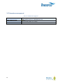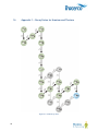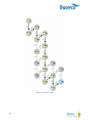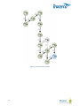
1
MN1007-P3 10/01/13
1
Contents
1
Introduction and Scope ......................................................................................................................................... 6
1.1 Introduction ................................................................................................................................................... 6
1.2 Scope ............................................................................................................................................................ 6
2
Naturally Occurring Radioactivity – an overview .................................................................................................. 6
2.1 Introduction ................................................................................................................................................... 6
2.2 Radioactivity in Oil and Gas Installations ..................................................................................................... 7
3
Operational Options .............................................................................................................................................. 8
3.1 Probe Selection............................................................................................................................................. 8
3.1.1
Geiger Müller End Window (Pancake) Probe ....................................................................................... 8
3.1.2
Scintillation Probe ............................................................................................................................... 11
3.2 NORM assessment criteria ......................................................................................................................... 13
3.2.1
Assessment using cps measurement ................................................................................................. 13
3.2.2
Assessment using surface activity (Bq/cm ) ....................................................................................... 13
3.2.3
Dose rate ............................................................................................................................................ 14
3.2.4
Specific activity ................................................................................................................................... 14
2
3.3 Background Measurement .......................................................................................................................... 15
4
Tracerco NORM Monitor-IS – Functional description ......................................................................................... 16
4.1 Handset monitor control keys ..................................................................................................................... 16
4.2 Operating the instrument ............................................................................................................................ 20
4.2.1
Connecting the probes ........................................................................................................................ 20
4.2.2
Removing the probe............................................................................................................................ 20
4.2.3
Switching on the instrument ................................................................................................................ 21
4.2.4
Start-up sequence illustration ............................................................................................................. 21
4.3 Measurement Modes for the Scintillator Probe. ......................................................................................... 22
4.3.1
cps Mode ............................................................................................................................................ 22
4.3.2
cps Minus Background Mode ............................................................................................................. 23
4.3.3
Dose Rate Mode ................................................................................................................................. 23
4.4 Modes of Operation for the Geiger Müller Probe. ....................................................................................... 24
4.4.1
cps Mode ............................................................................................................................................ 24
4.4.2
cps Minus Background Mode ............................................................................................................. 25
4.4.3
Becquerels per cm squared mode (Bq/cm ....................................................................................... 25
2)
4.5 Integration Function .................................................................................................................................... 27
4.5.1
Example – Making an integrated count measurement in cps mode ................................................... 27
4.6 Alarm activation in integration mode........................................................................................................... 28
4.7 Background Measurement .......................................................................................................................... 29
4.8 Alarm Configuration .................................................................................................................................... 30
2
4.8.1
Switching the alarm ON/OFF .............................................................................................................. 30
4.8.2
Selecting the alarm type ..................................................................................................................... 31
4.8.3
Setting Alarm Parameters ................................................................................................................... 32
LEVELs 32
FACtors 32
4.8.1
Alarm options for each measurement mode ....................................................................................... 33
4.8.2
Alarm notification ................................................................................................................................ 33
5
Adjusting the integration period .......................................................................................................................... 34
6
Locking the keypad ............................................................................................................................................. 36
7
Using the Instrument – taking a NORM measurement ....................................................................................... 37
8
Faults /Troubleshooting ...................................................................................................................................... 39
9
Display ranges – reading the screen .................................................................................................................. 40
10
Maintenance and Calibration .............................................................................................................................. 41
10.1 Cleaning ...................................................................................................................................................... 41
10.2 Handling ...................................................................................................................................................... 41
10.3 Calibration ................................................................................................................................................... 41
10.4 Equipment Inspection ................................................................................................................................. 42
10.5 Repair ......................................................................................................................................................... 42
11
Essential Safety Information For Hazardous Areas............................................................................................ 43
12
Contact Us .......................................................................................................................................................... 44
13
Technical Specification ....................................................................................................................................... 46
13.1 Radiological Type Tests ............................................................................................................................. 46
13.2 EMC Compliance Tests .............................................................................................................................. 46
13.3 Battery power .............................................................................................................................................. 46
13.4 Mechanical .................................................................................................................................................. 46
13.5 Environmental ............................................................................................................................................. 47
13.6 Radiological performance ........................................................................................................................... 47
13.6.1
Scintillator Probe ................................................................................................................................. 47
13.6.2
Geiger Müller Probe ............................................................................................................................ 47
13.7 Hazardous area approval ........................................................................................................................... 48
14. Appendix 1 – Decay Series for Uranium and Thorium ....................................................................................... 49
14
Appendix 2. - Menu diagrams ............................................................................................................................. 52
14.1 Scintillator probe Menu ............................................................................................................................... 52
14.2 Geiger Probe Menu..................................................................................................................................... 53
14.3 Alarm Menu ................................................................................................................................................. 54
3
Illustrations
Figure 1 - Geiger Müller (Pancake) Probe .................................................................................................................... 9
Figure 2 - Scintillation probe .......................................................................................................................................11
Figure 3 - Tracerco NORM Monitor–IS – key definitions ............................................................................................16
Figure 4 - Start-up sequence ......................................................................................................................................21
Figure 5 - cps readout screen .....................................................................................................................................22
Figure 6 - Background subtracted CPS screen ..........................................................................................................23
Figure 7 - Dose Rate screen with SI units ..................................................................................................................23
Figure 8 - Dose rate screen with US units ..................................................................................................................24
Figure 9 - cps readout screen .....................................................................................................................................24
Figure 10 - Background subtracted CPS screen ........................................................................................................25
Figure 11 - Radionuclide selection in Bq/cm2 mode ...................................................................................................26
2
Figure 12 - Bq/cm mode – Reading screen with Lead-210 (wet) selected ...............................................................26
Figure 13 - cps integration screen ..............................................................................................................................27
Figure 14 - Integration termination .............................................................................................................................27
Figure 15 - Alarm operation with Integration mode ....................................................................................................28
Figure 16 - Background measurement .......................................................................................................................29
Figure 17 - Alarm ON/OFF selection ..........................................................................................................................30
Figure 18 - LEVEL / FACt selection ............................................................................................................................31
Figure 19 - Integration period configuration ................................................................................................................34
Figure 20 - Keypad lock ..............................................................................................................................................36
Figure 21 - Quick start guide to measurement ...........................................................................................................37
Figure 22 - Display ranges..........................................................................................................................................40
Figure 23 - U-238 Decay chain ...................................................................................................................................49
Figure 24 - U235 Decay Chain ...................................................................................................................................50
Figure 25 - Thorium-232 Decay Chain .......................................................................................................................51
Figure 26 - Complete scintillator probe menu .............................................................................................................52
Figure 27 - Complete Geiger probe menu ..................................................................................................................53
Figure 28 - Complete alarm menu ..............................................................................................................................54
Tables
Table 1 - Glossary ........................................................................................................................................................ 5
Table 2 – Measurement options for probes .................................................................................................................. 8
Table 3 – Alarm options when using cps for NORM assessment ..............................................................................13
Table 4 – Alarm options when using Bq/cm2 for NORM assessment ........................................................................14
Table 5 – Alarm options when using dose rate for NORM assessment .....................................................................14
Table 6 – Complete set of alarm options ....................................................................................................................33
Table 7 - Alarm indications .........................................................................................................................................33
Table 8 – Troubleshooting ..........................................................................................................................................39
Table 9 - Radiological type test ..................................................................................................................................46
Table 10 - EMC compliance .......................................................................................................................................46
Table 11 - Battery power ............................................................................................................................................46
Table 12 - Mechanical data ........................................................................................................................................46
Table 13 - Environmental specification .......................................................................................................................47
Table 14 - Scintillator probe specification ...................................................................................................................47
Table 15 - Geiger probe specification .........................................................................................................................47
Table 16 - Hazardous area approval ..........................................................................................................................48
4
Glossary
Table 1 - Glossary
NORM
cps
cpm
NaI
LSA
µSv/h
µR/h
EMC
ATEX
IP rating
IS
Scintillator
Isotope
Nuclide
Background radiation
Baseefa
RPA
RPS
RSO
2
Bq/cm
Alpha radiation
Beta radiation
Gamma radiation
5
Naturally Occurring Radioactive Material
Radiation activity measured in counts per second
Radiation activity measured in counts per minute
Sodium Iodide – scintillation crystal
Low Specific Activity
Micro-sieverts per hour. SI units for effective dose rate
Micro-roentgen per hour. Non-SI units for dose rate used in USA
Electromagnetic Compatibility
European Directive 94/9/EC applicable to equipment used in hazardous environments.
From French “Appareils destinés à être utilisés en ATmosphères Explosives”
Level of Ingress Protection against objects and liquid
Intrinsically Safe. Design concept, formally assessed and certified by a notified body,
which demonstrates that the instrument can be used safely in hazardous environments.
Material which produces photons in response to incident radiation
Member of an element group with the same number of protons but differing number of
neutrons in its nucleus.
A member of the set of approx. 3100 elements and their isotopes
The ionising radiation constantly present in the natural environment of the Earth, emitted
by natural and artificial sources
A notified body for ATEX approval
Radiation Protection Advisor. A qualified expert who advises on safe and compliant use
of Ionising radiations according to the Ionising Radiations Regulations 1999 (IRR99)
Radiation Protection Supervisor. An individual appointed to ensure compliance with local
rules and radiation regulations under IRR99
Radiation Safety Officer
A measure of surface activity. One Becquerel is equivalent to one disintegration per
second.
Radioactive decay resulting in the emission of a helium nucleus (e.g. Ra-226 Ra222)
Radioactive decay resulting in emission of an electron or positron (e.g. Pb-210 Bi210)
Radioactive decay in which a high energy photon occurs along with the decay particle(s)
(e.g. 47KeV γ Pb-210 Bi-210)
1 Introduction and Scope
1.1 Introduction
The Tracerco NORM Monitor-IS is an intrinsically safe portable contamination monitor which has been developed
specifically to meet the requirements of the Oil and Gas Industry; particularly the measurement of Naturally
Occurring Radioactive Material (NORM).
Its principal function is to detect and quantify naturally occurring radioactive isotopes under a wide range of
operational conditions.
The monitor kit provides a single instrument platform with dual probe option to deliver optimum measurement
capability under the most demanding circumstances.
Although specifically designed to overcome the technical and practical challenges of measuring NORM in the field,
the monitor is also able to detect a wide range of man-made isotopes.
1.2 Scope
This manual provides detailed operational and technical information for the Tracerco NORM Monitor-IS.
In addition, an introductory guide is presented which explains the origins, radiological nature and the challenges
which arise when attempting to carry out practical measurements and radiological assessments of typical Naturally
Occurring Radioactive Material (NORM) deposits.
2 Naturally Occurring Radioactivity – an overview
2.1 Introduction
Radioactivity occurs naturally in the environment due to the presence of decay products from Uranium and
Thorium. These isotopes have extremely long half-lives. For example:
Uranium-235:
Uranium-238:
Thorium-232:
700 million years
4.5 billion years
14 billion years
The parent uranium and thorium isotopes decay to produce a series of other radioactive daughter isotopes of
widely differing half-lives. Eventually, through the course of time, these result in a stable isotope of Lead. A
schematic of the decay chains for each nuclide series is illustrated in Appendix 1 – Decay Series for Uranium and
Thorium
If the radioactive parent is undisturbed for a sufficiently long period of time, a condition of equilibrium is established
in which all radioactivity levels are equal. Removal of all or an amount of a nuclide from the decay scheme will
disturb this equilibrium and reduce the concentration of corresponding decay products. In a situation of true
6
radioactive equilibrium, all nuclides will be present at the same level of radioactivity. The natural decay series are
complex and, in theory, up to 48 separate radionuclides may exist in scales which have been derived from a
mixture of the Uranium and Thorium decay products.
In reality the isotopes of uranium-235, uranium-238 and thorium are rarely detected in scales themselves. This is
thought to reflect the low solubility of such materials in the water within the reservoir. It is more usual to detect the
more soluble decay products of each series in the form of radium isotopes and their subsequent daughter products.
The result of these processes is that NORM contains many different radionuclides which emit a complex mix of
alpha, beta and gamma radiations. The relative amounts of radionuclides from the uranium and thorium decay
chains can also vary depending on the history of the reservoir and chemical composition; hence scales taken from
different locations often exhibit variations in radioactive composition.
Many of the isotopes in the various decay chains can be seen to have relatively short half-lives (minutes or hours)
and, if present in isolation, would very quickly decay and cease to generate any further radiological hazards. These
isotopes would technically be described as "unsupported" but in many cases they continue to remain present with
an unchanging level of radioactivity. This occurs because they are continuously being produced by other
radioisotopes in the decay chain such that there is a constant balance between production and decay leading to a
constant level of radioactivity; irrespective of the actual half-life. In this situation the decay scheme would be
considered to be in equilibrium and the shorter lived nuclide fully “supported” by its parent nuclide.
2.2 Radioactivity in Oil and Gas Installations
Radioactive materials from natural sources may arise in a number of forms within the oil and gas industry. A
common form of the material is known as Low Specific Activity or Naturally Occurring Radioactive Material
(LSA/NORM) scale. It frequently arises within oil and gas installations due to a process of selective chemical
deposition. Radioactive isotopes, together with a wide variety of other chemicals, may be leached from reservoir
rock and become dissolved within the reservoir formation water.
In oil and gas installations, where water injection of seawater is used to promote the recovery of oil, the presence of
sulphate-rich injection waters can give rise to the deposition of barium and strontium sulphate scales. These scales
may incorporate radioactive isotopes derived from the presence of uranium and thorium in the formation rock and
can produce significant scaling of pipework and vessels; thereby reducing the flow of liquids and affecting the
efficiency of control systems.
The laydown of radioactive scale can lead to significant external radiation levels on the outside of production
equipment. This raises the possibility of exposure to personnel from contamination by ingestion of radioactive
material when equipment is handled or cleaned during scale removal operations. Similarly, scale and silt may be
deposited in the equipment of onshore terminals where crude oil is delivered from offshore installations via marine
pipelines.
An additional problem may arise in gas production and associated handling systems from the presence of radon
gas generated by radium isotopes; both in formation rock or water and in LSA/NORM scales. This radioactive gas
can contaminate the production gas to significant levels and will decay to particulate-forming radioisotopes such as
lead-210 and polonium-210 which can also be deposited in equipment of the gas production system.
These deposits can be radiologically significant and pose potential hazards to health when equipment is opened
up. It is not uncommon for significant quantities of unsupported lead-210 or polonium-210 to be transported from a
reservoir in the gaseous phase. In such circumstances the availability of these radionuclides reflects their chemical
and physical properties and the historical levels of the radioactivity which over time have built up in the reservoir.
7
3 Operational Options
The Tracerco NORM Monitor-IS has been designed to provide a versatile instrument which will enable the
operator to confidently detect and quantify contamination arising from NORM under most environmental conditions.
In order to achieve this versatility, the instrument is provided as a single data processing unit with the choice of two
types of radiation detection probes.
To realise the full capability of the instrument, it is important that the operator understands the technical
advantages of each probe and the circumstances under which they should be deployed.
3.1 Probe Selection
Although, in general terms, both the Geiger Müller (GM) and Scintillator-based probes will detect the presence of
NORM under most environmental conditions, there can be significant variations in detection sensitivity for different
scale types.
The following table provides guidance on the selection of probe for a particular NORM measurement application.
The table has been compiled on the basis that environmental background radiation is comparable to that found in
an offshore facility and there are no local abnormal circumstances – for example, the presence of local scale
storage containers will affect the detection capability of the scintillation probe due to a higher background radiation
reading.
This guidance is based on monitoring experience and the known technical characteristics of each probe. The
operator should always observe local operating procedures and, where appropriate, seek confirmation from the
appointed RPS or RPA.
Table 2 – Measurement options for probes
Type of measurement
Radium scale with readily accessible dry surface
Radium scale with significant water, oil or sludge deposition
Radium scale contaminated tubulars < 4” diameter (100mm)
Radium scale deposition using external pipe surface survey
measurements
Lead-210 scale with readily accessible surface ( wet or dry)
3.1.1
Suggested probe
Technology
Tracerco part
ref.
Geiger Müller
SA-49
Scintillator
SA-50
Scintillator
SA-50
Scintillator
SA-50
Geiger Müller
SA-49
Geiger Müller End Window (Pancake) Probe
The Geiger Müller probe utilises a thin window detector which, although capable of detecting gamma radiation, is
particularly sensitive to the surface measurement of alpha and beta radiation.
The Geiger Müller probe’s high sensitivity to alpha and beta is ideally suited to the measurement of lead-210 and
polonium-210 which are commonly found in gas producing facilities where NORM is transported in the form of the
gas radon-222.
8
Measurements may be taken in units of counts per second (cps) or - in the case where specific nuclides have been
2
selected - Becquerels per square cm (Bq/cm ).
2
The Bq/cm measurement function is used to quantify the levels of surface activity of a particular nuclide. It is
important that the users have prior knowledge of the type of nuclides present in the deposition so that the
measurements can be set up and interpreted correctly.
Contact [email protected] for further details regarding radionuclide spectrum analysis of
sample materials.
Figure 1 - Geiger Müller (Pancake) Probe
The detection sensitivity of the probe for alpha and beta emissions from scale materials may be significantly
reduced if the surface is wet or obscured by oily deposits.
Although in such circumstances the probe will continue to respond to any gamma ray emissions with only a limited
reduction in sensitivity, the reduced contribution from the alpha and beta particle detection will result in a significant
overall loss in sensitivity relative to a dry surface.
The Geiger probe has been calibrated with a number of response factors to allow measurement of Bq/cm2 for
specific nuclides. The nuclide options which are provided includes Radium-226 in the form of wet or dry scales and
Lead-210, again in the form of wet or dry scales. The operator is able to select the required nuclide through the
instrument’s configuration menu [See section 0]
9
The provision of a wet and dry option reflects the absorption of alpha and, to a lesser extent, beta radiation by
water and oil on the surface of the scale.
The response factors have been factory set under a calibration conditions where the probe is placed
directly above the scale surface at a distance of 2mm.
10
3.1.2
Scintillation Probe
The scintillation probe utilises an inorganic scintillator crystal which is very sensitive to the detection of gamma
radiation. It may also detect the higher energy beta radiation emitted by certain nuclides in the natural activity
decay chain.
A focus on gamma radiation detection sensitivity makes the scintillation probe ideal for measuring radium nuclides
and the associated decay chains. The probe has been designed to provide optimum radiation collection efficiency
without significantly reducing the ruggedness of the probe.
The nature of the design provides for near 360 degree collection of radiation thus providing an extremely effective
monitor for pipe internals.
Figure 2 - Scintillation probe
High gamma radiation sensitivity is particularly suited to detecting NORM through pipe or vessel walls where
internal monitoring is not possible and access limited to the external surfaces. In these situations the probe can be
used in an end-on configuration to directly monitor against the surface of interest.
The potential problems associated with the Geiger Müller probe - where wet or oily surface contamination of scale
limits detection of alpha and beta radiation - are largely overcome by the use of the scintillation based probe:
gamma ray emissions from scale are relatively unaffected by the presence of small quantities of oil and water.
An exception to the above is where areas of known Pb-210 deposition exist. In this case the GM probe will be
more effective.
11
The Scintillation Probe can measure in units of cps or dose rate. The dose rate response is calibrated against a
nationally traceable caesium-137 source.
The Scintillation Probe dose rate output is designed specifically for the methods of NORM screening required
by North American regulators. General dose rate surveys using the probe are not recommended.
The response of all scintillation detectors vary with radiation energy and the gamma ray energies associated with
caesium-137 are significantly different to those arising from NORM.
[See calibration details in Section 10.3]
12
3.2 NORM assessment criteria
There are various measures of the radiological significance of NORM. The assessment criteria favoured by local
regulators regarding NORM limits can vary from region to region.
The NORM Monitor-IS is designed so that it will accommodate all current assessment criteria.
For each assessment criteria the NORM Monitor-IS provides user-configurable alarms which can be set to reflect
the local rule PASS/FAIL criteria.
[See section 4.8 for alarm setting options]
The range of known assessment criteria is described in the following section.
The operator should always seek guidance from the designated RPA, RSO or RPS when selecting an
instrument for measuring NORM and observe local procedures in relation to any planned radiation monitoring
operations.
3.2.1
Assessment using cps measurement
The NORM Monitor-IS may be operated in cps or cps minus background mode, with either the GM Probe or the
Scintillator Probe.
The PASS/FAIL alarm criteria are summarised in the following table. These assessment methods are commonly
used in the UK and Middle East oil and gas sectors.
Table 3 – Alarm options when using cps for NORM assessment
Operating mode
Cps
cps - background
Alarm type
Level
Level
cps - background
Factor
3.2.2
Description
Alarm activated when total cps exceeds user-configured level
Alarm activated when cps above background radiation exceeds userconfigured level
Alarm activated when a multiple of background radiation is exceeded.
Assessment using surface activity (Bq/cm2)
Surface activity measured in Bq/cm2 is less commonly used in NORM assessment but may offer the operator
useful information - provided the type of nuclide is known.
[See also Section 3.1 Probe Selection]
13
The NORM Monitor-IS Geiger Müller probe is calibrated with response factors for lead-210 and radium-226.
Selection of the appropriate nuclide for the particular NORM samples allows the user to set PASS/FAIL criteria is
summarised as follows.
2
Table 4 – Alarm options when using Bq/cm for NORM assessment
Operating mode
2
Bq/cm
3.2.3
Alarm type
Level
Description
2
Alarm activated when Bq/cm exceeds user-configured level
Dose rate
Legislative requirements, typically in the US, require operators to assess NORM on the basis of the direct radiation
dose rate which would be experienced by a worker at the nearest “accessible” location to the contaminated item.
This requirement is satisfied with the Scintillation Probe which can take measurements in units of µSv/h or µR/h.
The NORM Monitor IS dose rate output is calibrated by Tracerco against a traceable Cs-137 source.
[See Section 10.3]
Table 5 – Alarm options when using dose rate for NORM assessment
Operating mode
Dose rate
Dose rate minus
background
Dose rate minus
background
3.2.4
Alarm type
Level
Level
Factor
Description
Alarm activated when total dose rate exceeds user-configured level
Alarm activated when dose rate above background dose rate
exceeds user-configured level
Alarm activated when a multiple of background dose rate is exceeded.
Specific activity
Specific activity in Bq/g is used as the fundamental measure of NORM activity. This measurement is performed by
Tracerco in laboratory conditions using highly complex measurement instrumentation.
Contact [email protected] for further details regarding radionuclide spectrum analysis of NORM
samples.
14
3.3 Background Measurement
An important aspect which the operator should consider when assessing the relative sensitivities of the two probes
is the background radiation level.
The Geiger Probe will only be significantly affected by very local sources of radiation and will typically display a
very low and predictable background count rate - whether deployed onshore or offshore. A normal background
count rate of less than 1 cps is typical.
The Scintillation Probe has a much greater environmental background count and can be significantly affected by
local geology. The lowest background values can be achieved in offshore or desert environments but can rise
substantially onshore depending on the precise nature of the locality. The statistical uncertainty in background must
therefore always be considered when determining the sensitivity of the probe to sample radiation in any given
situation.
[See Section 4.7 for details on measuring and saving background radiation levels]
15
4 Tracerco NORM Monitor-IS – Functional description
4.1 Handset monitor control keys
Figure 3 - Tracerco NORM Monitor–IS – key definitions
16
Analogue / Digital Screen
Digital readout displays radiation levels detected by the probe in user selectable units. The LEDs provide
operational status information.
Analogue dial representation provides an animated auto-ranging readout.
The meter may be configured to show counts (cps or cpm), dose rate (µSv/h or µR/h) or Bq/cm2.
Instrument on/off key
Push key to turn the monitor power on or off.
Speaker / Alarm key
Press to silence audible clicking during radiation measurements. Extended press for 3 seconds provides entry to
Alarm setting menu. [See Section 4.8]
The key is dual purpose and provides the means to decrease (-) the displayed value in the alarm or integration
configuration menus.
Rate/Int./Stop key
This key allows the operator to select a measurement mode which gives a more statistically accurate result than
that using the real-time rate method.
When the key is pressed, the instrument will take a measurement over a pre-configured period of time (for example
17
15 seconds). The user is presented with a time-averaged result on the display which gradually finds a mean value
over the duration of the measurement
Colour-coded LEDs above the instrument’s display screen indicate the current status of this measurement process.
[See Section 4.5 for more details on the integration function]
Select/Backlight key
The dual function key is used to select options from the alarm and integrate menus as well as activate the display
backlight.
Following activation, the backlight will operate for 20 seconds before switching off.
Mode (+) key
The primary key function is to step through the various measurement modes of the instrument. Each key-press
moves to the next unit option available for the probe attached.
The dual function key is also used to increase the alarm and integrate period parameters (+) when these menu
options are selected. [See Sections 4.8 & 5 on alarm and integration period configuration]
Log Back-ground key
This key is used to record and store background radiation levels.
Following key-press, a one minute background count is initiated and the result stored in memory. The result is used
in measurement modes where background compensation is factored into the value output to the display.
This process overwrites any previous value of background which is stored in memory.
18
To use any of the background adjusted modes of operation (including Bq/cm2), the user must take a background
reading for the chosen probe.
[See section 4.7 for further information on background measurement]
Probe Connection
Each probe is supplied with a flying lead terminated with an industrial specification IP68 (mated condition) coupling
connector [See Section 4.2.1 – Connecting the probe]
Note that the plug and socket are polarised. Please observe the red dot registration markings when connecting
the probes.
Indicator LEDs
Three LEDs indicate the current processing stage when using the integration measurement mode. The integration
measurement sequence is shown below.
1. Green rate LED – indicates that the measurement is in real-time. The display reading will fluctuate according to
the random nature of the radiation source.
2. Amber integrate LED – indicates that the instrument is busy. The LED will continue to flash over the duration
of the integration period.
During this period the display continues to show an averaged measurement with a one second refresh rate.
3. Red stop LED – indicates that the measurement is complete. The display no longer updates while the red LED
is flashing.
Press the Rate/Int./Stop
key again and the instrument returns to rate mode (1). The sequence is now complete.
[See also Section 4.5 Integration Function]
19
4.2 Operating the instrument
4.2.1
Connecting the probes
Each probe is supplied with a flexible (“curly”) cable terminated with a polarised industrial grade plug. Connection
to the hand-held monitor is made via a panel mount socket connection as shown below.
•
Rotate the probe plug so that the red marker is uppermost. Align the marker with the corresponding red dot
marker on the handset-mounted socket and push firmly.
A successful connection is confirmed by an audible and tactile ‘click’ of the latching mechanism.
Switch the monitor on and observe that the initialisation sequence is carried out – [See Section 4.2.3 – Switching
on the instrument]
4.2.2
Removing the probe
Switch the monitor off.
Hold the probe plug by the machined grip and pull firmly away from the handset.
20
4.2.3
Switching on the instrument
Pressing the power
key will turn on the monitor. A self-test routine enables all LCD segments and the three
indicator LEDs are illuminated in sequence.
Following the initialisation, visual acknowledgement of the selected probe type is displayed briefly as illustrated
below. SA-49 indicates the GM probe is connected; SA-50 indicates the Scintillator Probe is connected.
The start-up sequence is complete once the green LED starts flashing. The monitor is now ready for use.
At this stage the unit measurement presented to the user is dependent upon the operating mode and alarm
settings used when the instrument was last switched off. In the illustration below the instrument was last used in
cps mode and no alarm was set.
4.2.4
Start-up sequence illustration
Figure 4 - Start-up sequence
21
4.3
Measurement Modes for the Scintillator Probe.
Following initialisation – see previous section - the user may choose to change the measurement unit mode. The
various measurement modes for the scintillator probe are:
•
•
•
cps count rate (or cpm)
background subtracted cps count rate (or cpm)
Dose rate in µSv/h (or µR/h)
In each case it is possible to utilise the integration function whereby the displayed reading is averaged over a
period of time.
Note: The NORM Monitor-IS is capable of displaying SI units as well as non-IS units (primarily US market). Cps or
cpm & Sv/h or µR/h are factory set parameters and not configurable in the field.
4.3.1
cps Mode
Press the mode
key until the “cps” text appears on the LCD display as shown.
Figure 5 - cps readout screen
This screen provides a bar graph and digital display indication of the radioactivity detected by the probe in counts
per second (cps).
In cps mode the value displayed indicates the total count rate detected by the probe and includes any contribution
from environmental background radioactivity.
The green indicator LED will flash whilst the instrument is counting in this measuring mode
22
4.3.2
cps Minus Background Mode
key to change the measuring units from cps to cps minus background mode.
Press the Mode
The display shows a bar graph as well as digital readout. The measurement units and mode are indicated by the
“cps” and “– Background” text.
In this mode the digital display will show the cps count rate with the last stored background count subtracted.
Figure 6 - Background subtracted CPS screen
The value subtracted for background cps will be that held in memory by the instrument. The operator may update
the background value at any time. [See section 4.7]
Stored background counts are held for each probe type. If the SA50 scintillator probe and SA49 GM probe are
interchanged, the corresponding background reading for that probe type is automatically loaded and used in
the background subtraction calculation.
4.3.3
Dose Rate Mode
Press the Mode key to change the measuring units from cps minus background to Dose Rate mode
The screen will show the analogue scale and digital display in µSv/h units. If the instrument has been configured for
use in the USA then these units will be displayed in µR/h.
Figure 7 - Dose Rate screen with SI units
23
Figure 8 - Dose rate screen with US units
The green LED indicates that the instrument is recording data in real-time.
4.4 Modes of Operation for the Geiger Müller Probe.
Following initialisation – Section 4.2.4 - the user may choose to change the measurement unit mode. The various
measurement modes for the Geiger Müller probe are:
•
•
•
cps count rate (or cpm)
background subtracted cps count rate (or cpm)
Bq/cm2 (background subtraction implicit in this mode)
Note: The NORM Monitor-IS is capable of displaying SI units as well as non-IS units (primarily US market). Cps
and cpm are factory-set parameters and not configurable in the field.
In each case it is possible to select an integration mode where the readout is averaged over a period of time; thus
giving the option to take a more statistically accurate measurement.
4.4.1
cps Mode
Figure 9 - cps readout screen
This screen provides a bar graph and digital display indication of the radioactivity detected by the probe in counts
per second (cps).
In cps mode the value displayed indicates the total count rate detected by the probe and includes any contribution
from environmental background radioactivity.
The green indicator LED will flash whilst the instrument is counting in this measuring mode
24
4.4.2
cps Minus Background Mode
Press the Mode
key to change the measuring units from cps to cps minus background mode.
The display shows an analogue scale and digital numeral readout. The measurement units and mode are indicated
by the “cps” and “– Background” text.
In this mode the digital display will show the cps count rate with the last stored background count subtracted.
Figure 10 - Background subtracted CPS screen
The value subtracted for background cps will be that held in memory by the instrument. The operator may update
the background value at any time. [See section 4.7]
Stored background counts are held for each probe type. When the SA50 scintillator probe and SA49 GM probe
are interchanged, then the corresponding background readings are automatically loaded.
4.4.3
Becquerels per cm squared mode (Bq/cm2)
This mode of operation uses a background-subtracted measurement along with a factory set calibration factor in
2
order to calculate the Bq/cm response. The user should ensure that a valid background reading has been logged
prior to the target measurement.
This operating mode is intended for use where a specific nuclide is known to exist in the source of scale
contamination to be measured. To carry out the measurement the user should select the Bq/cm2operating mode
then select the required nuclide from the following list:
•
•
•
•
25
Radium-226 wet (Ra226w)
Radium-226 dry (Ra226 d)
Lead-120 wet (Pb210w)
Lead-120 dry (Pb210 d)
4.4.3.1 Selecting the radionuclide
1.
2.
3.
4.
Select Bq/m2 mode by repeatedly pressing the Mode key.
Press the Select key to enter the nuclide selection menu
Press the Mode key to cycle through the radionuclide options.
2
Return to the Bq/cm reading screen by pressing the Select key
2
Figure 11 - Radionuclide selection in Bq/cm mode
2
Figure 12 - Bq/cm mode – Reading screen with Lead-210 (wet) selected
26
4.5 Integration Function
Each of the operating modes detailed in the above sections may utilise the integration measurement function.
4.5.1
Example – Making an integrated count measurement in cps mode
Figure 13 - cps integration screen
A single press of the Rate/Int./Stop
key starts the integrated cps measurement.
The period over which the measurement is recorded (the integration period) is detailed in Section 4.5.
The statistical variation of this count will reduce as the accumulated count increases. The operator will see the
displayed value gradually stabilise as the counting period progresses.
The operator may terminate the integration period manually by pressing the Rate/Int./Stop
latest updated cps value will be displayed.
key; whereupon the
The amber integrate LED will flash during the measurement period. The red Stop LED will flash following the end
of the integration period or after manual termination.
Figure 14 - Integration termination
The stop screen gives the opportunity for the user to log the reading before proceeding to the next operation /
measurement.
Pressing the Rate/Int./Stop
key a final time will return the instrument to normal ("real time") measurement rate
mode; visual confirmation being indicated with a flashing green Rate LED.
27
4.6 Alarm activation in integration mode
Whilst making an integrated measurement, alarm activation will not be invoked until after the integration period has
expired.
If at the end of the integration period the alarm level is exceeded, then all three indicator LEDs will flash in unison
and the sounder will be activated.
Moving the probe away from the source to a position where the radiation is below the alarm threshold will disable
the sound but leave the LEDs flashing.
The audio and visual alarm operation is summarised in the following illustration.
[See also Section 4.8.2 Alarm notification table]
Figure 15 - Alarm operation with Integration mode
28
4.7 Background Measurement
It is good practice to update the background value held in the instrument at regular intervals; particularly where
there has been a significant change in the environment where monitoring work is being carried out; or where the
operator is uncertain of the value held in memory.
The measurement takes 60 seconds and thus provides a statistically accurate count value for use with background
subtraction measurement modes.
If using more than one probe type, ensure that a background reading is taken for each type (ie SA50 & SA49).
Press the Log Back-ground key. The display will begin to flash indicating that a background measurement is in
progress. The data presented represents a running average of the current measurement.
Figure 16 - Background measurement
After a period of one minute the monitor will cease counting and the new background value in cps (or cpm) will be
displayed. The operator can accept this value or repeat the count by pressing the Log Back-ground key once
more.
Press the Rate/Int./Stop
key to accept the new reading and automatically update the value held in memory.
The instrument will then return to its previous measuring mode.
29
4.8 Alarm Configuration
Alarm levels may be configured for each measurement mode (cps (or cpm); µSv/h (or µR/h); Bq/cm2 ) and are
retained in memory following power down or battery replacement.
The levels apply to the probe type connected. For example, the cps alarm level configured for the scintillation
(SA50) probe may be given a different value to that of the corresponding cps alarm level for the GM probe.
Alarms may be enabled individually for each probe and measurement mode – as indicated by the on-screen alarm
symbol
.
The alarm status (enabled/disabled) is retained following power down or battery replacement.
4.8.1
Switching the alarm ON/OFF
The instrument’s high pitched alarm sounder may be enabled and disabled using the configuration menu.
The comprehensive range of alarm options are either based on a single numerical value (LEVEL) or a multiple of
the background level (FACt or.)
To access the Alarm settings, hold down the alarm
key for 3 seconds.
Note: momentary operation of the key will toggle the activity ‘click’ sounder on and off only.
The screen will display one of the two options shown below depending on current alarm status.
Figure 17 - Alarm ON/OFF selection
30
Pressing the mode key
the Select
will toggle the alarm ON / OFF condition. If the screen display shows A-OFF, pressing
key will return the instrument to the measuring mode.
Note: that the alarm activation will only relate to the instrument’s current measuring mode. i.e. cps, Bq/cm2 or
Dose Rate.
4.8.2
Selecting the alarm type
Having enabled the alarm for the current measurement mode, select the type of alarm according to the prescribed
NORM assessment procedure [See Section 3.2]
Pressing the Mode
key will toggle between the LEVEL and FACt options:
Figure 18 - LEVEL / FACt selection
Note: FACt option is only available for measurement modes which include background subtraction
In background subtraction measurement modes the value applied to LEVEL is the measurement above the
background count at which the alarm is activated.
31
4.8.3
Setting Alarm Parameters
LEVELs
Alarm LEVELs are entered as a numeric value and are related directly to the value which is displayed on the
instrument for the relevant measurement mode.
Having previously selected the LEVEL/FACt preference, press the Select
Alarm (-)
key and use the Mode (+)
or
keys to increase or decrease the value displayed.
Confirm by pressing the Select
key. The instrument returns to the current measurement mode and applies the
alarm parameters for that measurement mode and probe.
LEVEL setting example 1
Measuring mode: cps
Alarm configuration: LEVEL = 5 cps.
Result: Alarm triggered when the display indicates ≥ 5 cps.
LEVEL setting example 2
Measuring mode: cps - background
Alarm configuration: LEVEL = 5 cps.
Result: Alarm triggered when the display indicates ≥ 5 cps. This equates to an actual count rate of 5 + stored
background count.
FACtors
The FACt option allows the alarm to be set as a multiple of the stored background measurement.
Having previously selected the LEVEL/FACt preference, press the Select
Alarm (-)
key and use the Mode (+)
to increase or decrease the value.
Confirm the setting by pressing the Select
key. The instrument returns to the current measurement mode.
FACt setting example 1 (typ. Scintillator on-shore)
Measuring mode:
cps - background
Alarm mode:
FACt
Alarm parameter:
2
Stored background count:
20 cps
Result: Alarm triggered when displayed reading ≥ 20cps [ (2 x background) - background ]
FACt setting example 2 (typ. GM probe)
Measuring mode:
cps - background
Alarm mode:
FACt
Alarm parameter:
3
Stored background count:
0.5 cps
Result: Alarm triggered when displayed reading ≥1 cps [ (3 x background) - background ]
32
or
4.8.1
Alarm options for each measurement mode
Table 6 – Complete set of alarm options
Operating mode
Cps
cps - background
Alarm type
Level
Level
cps - background
2
Bq/cm
Dose rate
Dose rate minus
background
Dose rate minus
background
Factor
Level
Level
Level
4.8.2
Description
Alarm activated when total cps exceeds user-configured level
Alarm activated when cps above background radiation exceeds userconfigured level
Alarm activated when a multiple of background radiation is exceeded.
2
Alarm activated when Bq/cm exceeds user-configured level
Alarm activated when total dose rate exceeds user-configured level
Alarm activated when dose rate above background dose rate
exceeds user-configured level
Alarm activated when a multiple of background dose rate is exceeded.
Factor
Alarm notification
The operator is alerted to an alarm condition using a combination of audio-visual indicators.
The alarm indications are summarised in the following table.
Table 7 - Alarm indications
Mode
Audible alarm
Visual Alarm – LEDs
Rate mode – green LED flashing
Continuous high pitch
tone
None
Alarm indication on
LCD display
Flashing symbol
Integration in progress – amber LED
flashing
None
None
Flashing symbol
Integrated measurement complete
(stop) – source of radiation still
present
Integrated measurement complete
(stop) – source of radiation removed
Continuous high pitch
tone
3 x indicator LEDs
high frequency flash
Flashing symbol
None
3 x indicator LEDs
high frequency flash
None
Once an alarm is triggered, it may only be silenced by moving away from the source of radiation.
33
5 Adjusting the integration period
The versatility of the integration function is enhanced by the facility to configure the period over which the
measurement is taken.
When the detected count rate is low, it may be advantageous to take a measurement over an extended period;
thereby minimising the statistical error by giving an averaged count rate over the sample period.
Conversely, due to the nature of on-site operations, the measurement may be subject to time restriction. The user
may therefore decide to optimise the measurement period.
The following flow diagram details the integration period configuration procedure.
Figure 19 - Integration period configuration
Hold down the Rate/Int/Stop
or
key for 10 seconds. The display will replace the current readout with either
depending upon the previously selected integration mode.
Selecting the
•
•
mode invokes the behaviour detailed below.
Integration maximum period/timeout = 60 seconds
Integration ends if total count ≥ 1000
is intended to provide a default measurement mode where statistical accuracy of the results could be made
based on the parameters detailed above.
34
Selection of the
The +/- keys (
option provides the operator with a screen showing the current integration period in seconds.
/
) may now be used to adjust the period within the range 0 to 600 seconds.
Note. In the unlikely event that the user wishes to disable the integration button function, then setting the
integration period to “0” will render the Rate/Int/Stop
Pressing the Select
key non-operational.
key will commit the setting to memory and return the instrument to rate mode.
Mode and period parameters are retained in non-volatile memory. The instrument’s configuration therefore survives
power-cycle so that setup following power-on is unnecessary.
35
6 Locking the keypad
The operator, or supervisor, has the capability to lock the instrument keypad so that only essential functions are
enabled.
A combinational key-press locks out the Mode and Select functions thus leaving the operator with a single-modeuse instrument.
Having configured the reading mode along with alarm and integration period configuration the user – or supervisor
– may lock the keypad. The remaining effective key functions are:
Rate/Int./Stop*
Backlight
Log Background
Activity ‘click’ mute toggle
Activation / de-activation of the keypad is illustrated below.
Figure 20 - Keypad lock
*Note: In the case where the Rate/Int./Stop function is to be disabled during keypad lock, then the integration
period should be first set to zero [See Section 5]
36
7 Using the Instrument – taking a NORM measurement
Measurements of radioactivity at levels which are only slightly greater than background are subject to significant
statistical uncertainty.
A more precise result can be achieved by using the monitor in integration mode which allows counts to be
accumulated over a fixed time period.
The total accumulated count is then divided by the sample time to provide a statistically accurate, time averaged
counts per second (or counts per minute) or dose rate.
Operation:
1. Take background reading (required if using background subtraction modes only)
a) Move the probe to a location which will represent the background radiation datum point for the site and not
influenced by the source to be measured
b) Press Log Background
key as shown below
c) Wait until the red LED flashes. Press Rate/Int/Stop
to return to real-time rate display.
Figure 21 - Quick start guide to measurement
37
2. Select units.
key, cycle through the various options associated with each probe type. For the SA-50
Using the Mode
scintillation probe the options are:
• Cps
• Cps with background subtracted
• µSv/h
• µSv/h with background subtracted
3. Press Rate/Int./Stop
key.
This will start the measurement as indicated by the flashing amber LED.
The instrument will complete the measurement once the pre-set integration period has elapsed [See Section 5
Setting Integration Period.]
The user may also interrupt this measurement by pressing the Rate/Int/Stop
key.
4. Red LED flashes. The measurement is complete.
The measurement will continue to be displayed until the user presses the Rate/Int/Stop
key.
The instrument will now return to a live real-time display as indicated by the flashing green LED.
5. If at the end of the integration period the alarm level is exceeded, then all three indicator LEDs will flash in
unison and the sounder will be activated.
Removing the source of radiation will clear the sounder but the LEDs will continue to flash until the user
key to return to rate mode.
presses the Rate/Int./Stop
[This operation is summarised in Section 4.6 Alarm activation in Integration Mode]
Note that the alarm operation in Integration mode is different from that in rate mode in which case the
alarm is activated immediately after levels are exceeded.
Note: the background count is stored in non-volatile memory so that the reading is retained even if the
instrument is switched off.
The operator is responsible for ensuring the background measurement is kept current and therefore applicable
to the measurement in hand. The site RPA (or deputy) will advise on frequency and location of background
radiation measurements
38
8 Faults /Troubleshooting
The following table shows error conditions and notification.
Table 8 – Troubleshooting
Fault
No probe detected
Notification
Low count rate
detected – possible
failure of probe
detector element or
cable
After 20 seconds of zero counts…
Actions
• Connect a compatible probe
• Examine cable and connector for
damage. In case of damage, return
to Tracerco for repair.
Move to an area of higher activity.
If error persists, return to Tracerco for
diagnosis
Further 20 seconds…
Low battery
Move to non-hazardous area and
change the battery.
Over range
Move away from source of radiation
39
9 Display ranges – reading the screen
The following images illustrate the range of the instrument according to each measurement unit selection.
Figure 22 - Display ranges
40
10 Maintenance and Calibration
The NORM Monitor-IS has been designed for reliable operation in heavily industrialised environments and should
provide many years of effective service provided attention is paid to basic operational maintenance.
10.1 Cleaning
The NORM Monitor-IS features a thermoplastic handset and Geiger probe housing which are manufactured from
materials with excellent chemical resistance and inherent antistatic properties. The plastic cases may be cleaned
by wiping with a slightly moistened cloth. A mild detergent may be used if required.
The Scintillator probe is manufactured from stainless steel and phosphor bronze. The IP67 enclosure is designed to
be hosed down thereby facilitating decontamination.
Care should be taken to protect the cable termination plugs during the cleaning process.
10.2 Handling
Maintenance of the mechanical integrity and antistatic properties of the NORM Monitor-IS housing are critical for
use in explosive atmospheres. While the NORM Monitor-IS has a tough design, unnecessary impacts, abrasions or
contact with harmful chemicals should be avoided.
Tracerco recommend that the monitor and its probes are transported in a suitably robust transit case.
The user is advised not to open the NORM Monitor-IS or any of its associated probes.
The NORM Monitor-IS kit has no serviceable parts and should be returned to Tracerco in the event of
damage. It is essential for safety integrity, that repair of this ATEX certified equipment is carried out by
qualified personnel in accordance with the appropriate standards and regulations.
10.3 Calibration
All probes are delivered ready-calibrated; the calibration data being held in the probe itself and loaded into the
handset once connected.
In surface activity (Bq/cm2) mode the Geiger Probe (SA49) has been calibrated against traceable plaques of
known nuclides.
The Scintillator Probe (SA50) in dose rate mode is calibrated against a traceable Cs-137 source.
When measuring dose rates where the source is known to contain Ra-226, the displayed rate will be in the order of
30% below that from a Cs-137 source with the same activity.
Ionising radiation legislation recommends that all operational radiation measurement devices are subjected to
regular inspection and testing. This recommendation includes performance checks and where appropriate,
recalibration of the monitor.
41
All NORM Monitor-IS probes are checked and calibrated immediately prior to despatch to the customer. Following this
initial procedure (or the regular inspection and calibration check), Tracerco engineers will set the next calibration check
due date within the probe’s memory.
To assist in providing customers with a more efficient and comprehensive service, Tracerco’s in-house database
holds records of all monitors supplied to customers, including details of inspections, repairs, replacements and
calibrations. This database provides a cradle-to-grave history for the tracking of radiation monitors.
Tracerco has several calibration and repair facilities throughout the world. Contact Tracerco customer services to find
your nearest facility.
10.4 Equipment Inspection
Tracerco recommends that all portable Hazardous Area approved instruments receive an annual inspection by an
appropriately trained technician. The requirement for annual inspection is consistent with EN 60079-17.
Tracerco are able to provide an appropriate inspection service and should be contacted for further details [See section
Error! Reference source not found.]
10.5 Repair
Repair of the equipment shall be carried out by suitably trained personnel in accordance with the applicable code
of practice e.g. IEC/EN 60079-19
All parts used in the repair of the NORM Monitor-IS must be supplied by Tracerco.
If the equipment is likely to come into contact with aggressive substances, it is the responsibility of the user to
take suitable precautions to ensure the type of protection provided by the equipment is not compromised.
42
11 Essential Safety Information For Hazardous Areas
The NORM Monitor-IS handset and probes are safe for use in hazardous areas described in the equipment
marking and according to the essential safety information stated below.
Marking details
ATEX Certificate number: Baseefa12ATEX0209X
IECEx Certificate number: IECExBAS12.0114X
ATEX Equipment Marking: Ex ia IIC T4 Ga (-20°C ≤ Ta ≤ +50°C)
Equipment category: II 1G
Approval standards
BS EN 60079-0:2012 – Explosive atmospheres. Equipment. General requirements
BS EN 60079-11:2012 – Explosive atmospheres. Equipment protection by intrinsic safety “i”
Limitations of hazardous area use
ATEX coding II 1G states that the equipment is for non-mining use (II) with highest protection (1) for gas (G)
atmospheres.
Electrical coding Ex ia IIC T4 Ga (-20°C ≤ Ta ≤ +50°C) states that the equipment is intrinsically safe (ia) for use in
zones 0, 1 and 2 and that it may be used in areas where flammable gas groups IIA, IIB, and IIC are present. T4
indicates that the equipment is suitable for use in flammable gasses with a T Class of T1, T2, T3 or T4. The
ambient working temperature for the equipment is -20°C - +50°C.
Conditions of safe use (indicated by “X” extension in certification number)
•
Care must be taken during transportation, removal and replacement of the scintillator from the PM Probe in
the hazardous area to avoid impact with the aluminium casing of the scintillator.
Practical safety points
•
•
•
43
Do not open the battery compartment in a hazardous area.
Use only the Duracell MX1604 or MN1604 alkaline manganese battery.
Lock the battery compartment by the screw in the compartment lid -do not over-tighten.
Do not use solvents on the handset monitor window.
12 Contact Us
Contact us at one of our Global Service Centres
Billingham, UK (Global Headquarters)
Tel:
+44 (0)1642 375171
Email: [email protected]
Kuala Lumpur, Malaysia
Tel:
+603 7803 4622 (GL)
Email: [email protected]
Houston, USA
Tel:
+1 281 291 7769
Email: [email protected]
Perth, Australia
Tel:
+61 (0)8 9209 3905
Email: [email protected]
Please visit the Tracerco website www.tracerco.com for details of other Tracerco offices and locations.
44
Tracerco manufacture a wide range of intrinsically safe and standard ration monitoring products.
Tracerco can provide a professional, rapid turnaround calibration and repair service as well as offering a hire
service for a range of monitors.
Our experience technicians can also provide an annual Hazardous Area Equipment Inspection as described by
IEC 60079-17
45
13 Technical Specification
13.1 Radiological Type Tests
Table 9 - Radiological type test
Instrument
NORM Monitor-IS with Geiger
probe
Applicable standard
BS EN 60325:2004
NORM Monitor-IS with Scintillation
detector
BS EN 62363:2011
Description
Radiation Protection Instrumentation – Alpha,
Beta and Alpha/Beta (Beta 60keV)
contamination meters and monitors
Radiation protection instrumentation – Portable
photon contamination meters
13.2 EMC Compliance Tests
Table 10 - EMC compliance
Applicable standards
BS EN 61326-1-2006
BS EN 61000-4-2:
1995+A1+A2:2001
BS EN 61000-4-3:2002
BS EN 61000-4-8:1993
BS EN 55011:2007
Description
Electrical equipment for measurement, control and laboratory use.
Electrostatic Discharge
Radiated Electromagnetic Field Immunity
Magnetic Field Immunity
Industrial, scientific and medical equipment – Radio-frequency disturbance
characteristics – Limits and methods of measurement
13.3 Battery power
Table 11 - Battery power
Technology
Format
Approved part numbers
Battery life (excluding backlight)
Low battery indication
Alkaline Manganese
PP3 (9v)
MX1604; MN1604
Scintillator probe: 82 hours
Geiger probe: 190 hours
7.8 Vd.c.
13.4 Mechanical
Table 12 - Mechanical data
Unit
Handset meter
Scintillator probe
Geiger probe
Holsters + belt
46
Dimensions / weight
250 x 110 x 50mm / 500g
220 x 42mm diameter / 746g
200 x 85 x 55mm / 483g
700g
13.5 Environmental
Table 13 - Environmental specification
Operating Temperature
Storage Temperature
Humidity
Shock
Ingress protection:
Scintillator probe
Geiger probe
Handset meter
-20 to +50°C
-20 to +50°C
0 – 95%
Drop tests according to BS EN 60079-0
IP67
IP34
IP65
13.6 Radiological performance
13.6.1 Scintillator Probe
Table 14 - Scintillator probe specification
Radiation detected
Sensor technology
Units
Dose rate
Alarms
gamma, beta
NaI(Tl) scintillation crystal
µSv; µRad; cps; cpm
0.000 – 50µSv/h (0.0 – 5,000µR/h)
Alarm levels configurable for full range in all units
Alarms configurable as defined numerical limit or as multiple factor of stored
background in 0.5 increments
Overload response
range displayed at 240,000 cps. Derived-units overload figure
dependent upon calibration factors.
Less than ±10% over temperature range -20 to +50°C
Variation with temperature
13.6.2 Geiger Müller Probe
Table 15 - Geiger probe specification
Radiation detected
Sensor technology
Units
Alarms
alpha, beta, gamma
Geiger Müller End Window (Pancake)
cps/cpm; Bq/cm2
Alarm levels configurable for full range in all units
Alarms configurable as defined numerical limit or as multiple factor of stored
background in 0.5 increments
Overload response
range displayed at 4000 cps. Derived-units overload figure dependent
upon calibration factors.
Less than ±10% over temperature range -20 to +50°C
Variation with temperature
47
13.7 Hazardous area approval
Table 16 - Hazardous area approval
Certification numbers
ATEX Equipment mark
48
ATEX certificate reference: 12ATEX0209X
IECEx certificate reference: IECExBAS12.0114X
II 1G
Ex ia IIC T4 Ga (-20°C ≤ Ta ≤ +50°C)
14.
Appendix 1 – Decay Series for Uranium and Thorium
Figure 23 - U-238 Decay chain
49
Figure 24 - U235 Decay Chain
50
Figure 25 - Thorium-232 Decay Chain
51
14 Appendix 2. - Menu diagrams
14.1 Scintillator probe Menu
Figure 26 - Complete scintillator probe menu
52
14.2 Geiger Probe Menu
Figure 27 - Complete Geiger probe menu
53
14.3 Alarm Menu
Figure 28 - Complete alarm menu
54