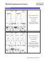
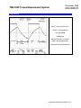
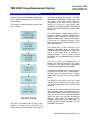
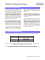
1
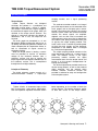
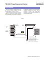
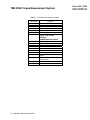
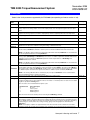
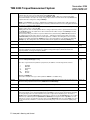
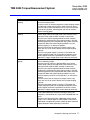
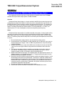
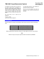
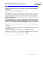
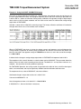
Sensotec - Lebow
Operating Instructions for the
TMS9000 Torque Measurement
Sensing and Control
Rev D: Nov. 2006
008-0688-00
TMS 9000 Torque Measurement System
November 2006
008-0688-00
Intended Use
Rotating torque sensors are intended for use
between a power source and its load. They may
be used to measure the power output of a drive
(such as an electric motor or gasoline engine)
2 Honeywell • Sensing and Control
and a suitable load. They are also used to
measure the torque required to operate a given
load.
November 2006
TMS 9000 Torque Measurement System
008-0688-00
Operating Principles
coupling module, and a signal processing
module.
Torque Sensor
Lebow Torque Sensors are designed
structures that perform in a predictable and
repeatable manner when a torque is applied.
This torque is translated into a signal voltage by
the resistance change of strain gages, which are
attached to the torque sensor structure. The
change in resistance indicates the degree of
deformation, and in turn, the torque on the
structure.
The strain gages are connected in a 4 arm
Wheatstone Bridge configuration which acts as
an adding and subtracting electrical network and
allows compensation for temperature effects as
well as cancellation of signals caused by
extraneous loading.
When the torque sensor is rotating, a means
must be provided to transfer an excitation
voltage to the rotational element from a
stationary surface, and also to transfer the
torque signal from the rotational element back to
the stationary surface. This is accomplished
through the use of digital telemetry.
The receiver-transmitter module is an integral
part of the torque sensor and is connected to the
strain gauges and to the epoxy glass annular
printed circuit board that contains the rotating
antenna system. Within the receiver-transmitter
module, the sensor signals are amplified,
digitized, and are then used to modulate the
radio frequency carrier wave that is detected by
the antenna after being transmitted across the
air gap by the caliper coupling module. That
same carrier wave is rectified to provide power
to drive the strain gauges and the electronic
components in the module, which is managed
by a miniature microprocessor.
The caliper coupling module connects to the
signal processing module via a simple co-axial
cable. The detector circuitry in the signal
processing module recovers the digital
measurement data from the torque sensor and
passes it to the second microprocessor for
scaling and linearizing.
The third microprocessor provides the drive to
the two analog outputs, as well as the standard
digital interfaces and the optional digital
interface modules. Extensive facilities are
provided in software for setup and configuration
of the complete system.
Principle of Telemetry
The digital telemetry system consists of a
receiver-transmitter module, a caliper-style
Bolting Information
Tighten all bolts, in incremental steps, to the
bolt manufacturers rated torque specification.
Use the respective sequence illustration shown
below depending on the number of bolts the
sensor requires. This bolting sequence applies
to both bolt circles of the torque sensor.
1
1
1
10
8
6
8
8
4
3
11
12
4
5
4
5
7
2
3
6
3
4
10
6
3
6
1
5
2
9
7
2
5
9
2
7
Honeywell • Sensing and Control 3
TMS 9000 Torque Measurement System
November 2006
008-0688-00
Installation and Set-up
Torque Sensor
The TMS 9000 series torque sensors may be
operated horizontally, vertically, or any angle in
between provided the load is applied through the
loading axis.
All torque sensors in this series have bolt
patterns that mate directly to standard industrial
couplings. When mounted, one of the flanges
should be mated to a good quality double flex
coupling or a driveshaft arrangement that
incorporates universal joints at each end. This is
designed to compensate for angular and parallel
misalignment.
Avoid applications that place extraneous loads
on the torque sensor.
Caliper Coupling Module
The caliper coupling module must be firmly
mounted to a non-rotating support structure. It
must be aligned with the epoxy glass annular
printed circuit board antenna so that the air gap
between the caliper and the antenna is
approximately equal on both sides. Care should
be taken to avoid any items touching one
another, and consideration should be given to
the effects of vibration as well as the free play in
any driveshaft sliding joints.
To assist in the process of aligning the caliper
and the antenna, a simple plastic alignment tool
is provided with each system. The tool is used to
hold the required clearance between the caliper
and the antenna while the caliper fixing bolts are
being tightened, and then is removed before the
sensor is rotated.
The tolerances for end-float (axial) are +/4.5mm (+/- 3/16”) and for run-out (radial) are +/1.0mm (+/- 1/16”). For installations where runout cannot be controlled within the specified
tolerance, the secondary coupling position can
be used. This is achieved by placing the edge of
the caliper in close proximity to the edge of the
antenna. In this position, the run-out tolerance
can be at least doubled, at the expense of a
reduced signal to noise ratio caused by the
higher incidence of data drop outs. The axial
4 Honeywell • Sensing and Control
tolerance is limited by the distance between the
caliper sections.
The caliper can also be mounted such that
only one side is in proximity to the antenna, if
the mounting arrangement does not allow for
placing of the antenna between the two sides of
the caliper.
Successful positioning of the caliper can be
confirmed by the presence of the ROTOR
ACTIVE light on the signal processing module.
The length of the RF cable connection
between the caliper coupling module and the
signal processing module is critical to system
performance (due to reflections and standing
waves). When using RG58 50-ohm cable, the
length must be maintained at 13.9 metres (45’6’’
feet) or a multiple thereof. When using Belden
89907 cable, length must be maintained at 17.6
metres (57 feet) or a multiple thereof. For cable
runs of less than 0.6 metre (2 feet), the cable
that is provided with the unit can be cut to the
required length. Otherwise, simply coil up any
excess length.
Signal Processing Module
The receiver is mounted remotely with the
coaxial cable being the only connection between
it and the caliper coupling module. The receiver
has holes provided for permanent mounting.
Request the appropriate certified drawing from
Lebow before making fixtures.
When deciding where to locate the signal
processing module, consideration should be
given to the type of output that will be used. If
the analog voltage or current output is to be
used, then the signal processing module should
be mounted in an area of low electrical noise
and the connection between the module and the
data acquisition equipment should be as short
as possible and should be made up from double
screened twisted pair cable. If the frequency
output or the digital output is to be used, then
the signal processing module can be mounted in
the electrically noisy area provided that good
quality dual screened twisted pair cables are
used.
November 2006
TMS 9000 Torque Measurement System
008-0688-00
Electrical Connections
The signal processing module features twopart plug and socket connectors and the
connection details are shown in Figure 2.
All cable connections should pass through the
cable glands, which when properly assembled,
provide adequate sealing to allow the module to
be operated in NEMA4 or IP65 environmental
conditions (occasional water splash). The RF
connection is made via the standard BNC
connector, and IP65 rated cable assemblies can
be supplied upon request.
Figure 2
JTAG Connectors
J9
SCU
Primary
Configuration
port
Port
Secondary
(expansion)
Expansion
port
Port
RS485 A
RS485 B
RS232 V+
RS232 RXD
RS232 TXD
RS232 0V
RS485 A
RS485 B
RS232 V+
RS232 RXD
RS232 TXD
RS232 0V
Power 0V
Power +12V
J10
DLU
Expansion connector J14
J2
RF Carrier
J7
ME0141-A
ME0141-B
J6
5-15kHz (0V)
5-15kHz
J4
4-20mA
4-20mA (0V)
J5
±10V
±10V (0V)
J3
ID label
J8
Expansion Connector J13
J1
BNC connector to Calliper module
Via standard RG58 co-axial cable:
Length 13.9m (45.6 ft) or multiples thereof
Via standard Belden 89907 cable:
Length 17.6m (57 ft) or multiples thereof.
Honeywell • Sensing and Control 5
TMS 9000 Torque Measurement System
TABLE 1: Connector and Jumper Functions
Connector
J1
J2
J3
J4
J5
J6
J7
J8
J9
J10
J11
J12
J13
J14
JP1
JP2
JP3
JP4
6 Honeywell • Sensing and Control
Function
DC Power 12 V
Primary RS485 port
Secondary RS485 port
Current loop output
Voltage output
Frequency output
Primary RS232 port
NOTE - THIS IS THE
DEFAULT
COMMUNICATIONS PORT
Secondary RS232 port
Factory use only
Factory use only
Expansion port
Memory expansion port
Primary RS232/RS485 default
select
Secondary RS232/RS485
default select
November 2006
008-0688-00
November 2006
TMS 9000 Torque Measurement System
008-0688-00
Command Set
Below is the list of parameters supported by the TMS 9000 (corresponding to firmware version v1.38) :
Parameter
Name
#A
Description
Data Type
Mode reporting access used by TMS Toolkit software to extract parameter information from the device.
Read only
#AnOutHigh
Sets or returns the value in engineering units applied to the input that will give 100% (maximum positive full
scale) output on the analog outputs. To invert the output polarity, enter the required negative full scale output
value.
Sets or returns the value in engineering units applied to the input that will give 0% (minimum negative full scale)
output on the analog outputs. To invert the output polarity, enter the required positive full scale output value.
Read/write
AuxBaud
Not yet supported.
Read/write
AuxOPType
Not yet supported.
Read/write
BaudRate
Not yet supported.
Read only
*CalCnts1*CalCnts9
#CalPoints
Internal calibration data. This is read only via TMS Toolkit and is viewable only in “CAL” level access. These
parameters are exposed to enable the saving and loading of calibration data only.
Read only
Sets the number of calibration points in use. Value must be between 2 and 9. Any change in #CalPoints should
be followed by a #CalReset command to clear the previous unwanted calibration data from the memories.
Read/write
#AnOutLow
#CalReset
#CalValue1
to
#CalValue9
#Counts
ErrFlag
Read/write
NOTE – all calibration data and all analog output setting data will be cleared by #CalReset. It is recommended
to save the parameter list before invoking #CalReset.
Resets all calibration information. When the reset command is issued, all calibration data and all settings of the
analog outputs (#AnOutHigh and #AnOutLow) are cleared so no reliable output will be available until all of the
calibration points specified by the #CalPoints parameter and the required values of #AnOutHigh and
#AnOutLow have been entered.
Command
NOTE – all calibration data and all analog output setting data will be cleared by #CalReset. It is recommended
to save the parameter list before invoking #CalReset.
These values are written in engineering units when the appropriate load is applied. Each of the nine parameters
can be written at any time. See Calibration section later in this document. NOTE – the values entered MUST be
in ascending order, starting with #CalValue1 (negative values count as lower than positive values). The number
of calibration points entered must be equal to the number of calibration points activated by #CalPoints.
Read/write
NOTE – the existing calibration data is overwritten by any new input of #CalValue1~9. It is recommended to
save the parameter list before entering new values.
Returns the raw A-D counts value derived from the ADC on the rotating sensor.
The ErrFlag parameter will indicate any errors that have occurred by returning a numeric value that is
comprised of binary values representing the various error states. i.e. the binary values for each error are added
together to produce the ErrFlag value.
The error states are not retained between power cycles.
Decimal Value
0
1
2
4
Read only
Read only
Error Description
No error.
Power cycled.
Output clamped.
Watchdog reset.
Once the errors have been read they can be reset using the RstErrFlag command.
#FastMode
Used to initiate raw throughput of data without scaling or filtering. Set this parameter to 1 to enable fast mode.
This setting is volatile so the device will revert to normal mode after the next Reset or the next power-up. Set to
zero to disable fast mode. When in fast mode, the internal raw A-D counts results are fed directly to the analog
output (voltage or current) without any scaling or filtering, giving a data throughput rate of 8.8 kHz (when
FiltLevel=1).
NOTE - the frequency output is not supported in fast mode. The fast mode can be scaled in the user’s data
acquisition system by using the shunt cal facility, and is intended to be used for dynamic measurements only.
Read/write
Honeywell • Sensing and Control 7
TMS 9000 Torque Measurement System
FiltLevel
November 2006
008-0688-00
Used to set the threshold of operation of the digital filter. Values are set as parts per 10000, meaning that to set
a threshold of 10% of the sensor rated capacity, then FiltLevel=1000
For a % step change in input, which is greater than (FiltLevel / 10000 * 100%), the new input value will be
passed immediately to the output. For a step change in input, which is below the threshold set by FiltLevel, the
output is filtered according to the setting of FiltSteps.
Read/write
#M
NOTE – when FiltLevel is set to 0 or 1, digital filtering is disabled. Factory default value is 100, representing a
threshold of 1% of sensor rated capacity (refer to the factory calibration data sheet or the rating plate attached to
the sensor to confirm the rated capacity)
Used to set the response time of the digital filter. Used in conjunction with FiltLevel to control the digital filtering
behavior. Value range is 1 through 1000.
Filtering takes the form of an RC equivalent where a change in input value, which is greater than the threshold
set by FiltLevel, causes the output value to be incremented in the number of steps set by FiltSteps. The filter
refresh rate is 1200 Hz.
Factory default setting is 10, which in conjunction with the factory default setting of FiltLevel=100 provides for
an output increment in the form of (x/2, x/3, x/4, x/5, x/6 …. x/10) where x=step change in input of more than
((FiltLevel/10000)*rated capacity). Given the filter update rate of 1200 Hz, the settling time to 63% final value
will be 8.3 ms (Update rate divided by FiltSteps) and to 1% final value will be 41.7 ms (Update rate divided by
FiltSteps x 5). The settling time to 0.1% final value will be 58.3 ms (Update rate divided by FiltSteps x 7).
Mode reporting access used by TMS Toolkit software to extract parameter information from the device.
Model
Returns the model name (TMS)
OpType
ParaCnt
Sets or returns the currently selected analog output where 0=current; 1=voltage; 2=frequency 10 kHz;
3=frequency 60 kHz, 4=current and frequency 10 kHz, 5=voltage and frequency 10 kHz, 6=current and
frequency 60 kHz, 7=voltage and frequency 60 kHz.
Returns the number of parameters in the device.
ParaItem
Set to the index number of the required parameter.
Write
ParaList
Returns the information on the parameter indexed by ParaItem.
Format: 'index,paraname,type’ a string.
Read
string
FiltSteps
Read/write
Read only
Read only
string
Read/write
Read
The value of type indicates the parameter’s properties by the addition of the following numerical values:
1
2
4
32
64
128
Readable
Writeable
Command
String
Numeric
Boolean
Example: ‘1,MODEL,33’
In the above example where type = 33 the parameter MODEL is a readable string.
Percent
Returns the value of the applied torque in percentage terms (0-100) where this range is the selected range over
which the analog outputs work and is set by #AnOutLow and #AnOutHigh.
Read only
Reset
Reset command to restart device and to implement parameter changes that require a reset.
Command
RstErrFlag
Reset all error flags.
Command
SysZero
Allows manual setting of the current Value or querying of the current zero offset being applied. The returned
value is the amount of zero offset being applied to the true Value. To zero the system, this parameter should be
set in engineering units to the value read when the system is supposed to be displaying zero. The action of
SysZero may be limited by #ZeroLimit as described above, in which case the flag ZeroOK will be set to 0. Note
that when any calibration parameter (#CalValue1~9, #CalReset) is changed, the value of SysZero is set to 0
and any zero offset is cancelled. This function, when used with #ZeroLimit, allows the current Value to be offset
to any desired level (remember to consider the dynamic loading range of the sensor itself when applying large
offsets)
Read/write
8 Honeywell • Sensing and Control
TMS 9000 Torque Measurement System
November 2006
008-0688-00
Value
Text memo field in which the name of the engineering units used for calibration can be stored for recall later.
Note that when reading some characters via a 7-segment display (TMS Toolkit uses a virtual 7-segment
display), some characters such as M will not display correctly.
Returns the value of the applied torque in calibrated engineering units.
Read only
Version
Returns the software version
Read only
ZeroNow
Sets the current Value to zero unless limited by #ZeroLimit as described above. The action performed by
ZeroNow is to clear any previous zero offset then compare the true Value to #ZeroLimit, then, to the extent
allowable by #ZeroLimit, write the true Value to SysZero, resulting in a new current Value of zero
Returns indication of 1 if the previous ZeroNow command was successful in setting the current Value to zero
and returns 0 if the action was limited by #ZeroLimit.
The limit in engineering units at which the ZeroNow command will be allowed to operate, relative to the
computed Value at zero load that was stored during the calibration process. Therefore #ZeroLimit represents
the maximum allowable difference between the “calibration” zero and the “current” zero. If the ZeroNow
command is issued when the current Value is greater than #ZeroLimit, then the current Value will be moved to
the extent allowed by #ZeroLimit and the flag ZeroOK will be set to 0. Factory setting is 50% of the calibrated
range. Note that #ZeroLimit is a bipolar setting, so it will be applied to both directions (+ and -) around the
calibration zero value.
Internal system zero data. This is read only via TMS Toolkit and is viewable only in “CAL” level access. This
parameter is exposed to enable the saving and loading of calibration and zero data.
Command
Units
ZeroOK
#ZeroLimit
*ZeroPVal
Read/Write
Read only
Read/Write
Read only
Honeywell • Sensing and Control 9
TMS 9000 Torque Measurement System
November 2006
008-0688-00
System Calibration
The TMS 9000 features nine-point
linearization and all calibration is achieved using
the following parameters:
#CalSteps
#CalReset
#CalValue1
#CalValue2
#CalValue3
#CalValue4
#CalValue5
#CalValue6
#CalValue7
#CalValue8
#CalValue9
The minimum number of calibration points is
2. Calibration points can be created in any order
provided that the values they contain are in
ascending order starting with #CalValue1.
Therefore, the lowest or the most negative
(counter-clockwise) calibration point should be
designated as #CalValue1.
The number of calibration points that are in
use is set by the parameter “#CalPoints”. Any
change to the value of #CalPoints should be
followed by the issuance of a “#CalReset”
command, to clear the old calibration values
from the EEPROM memories.
Calibration is achieved by applying known
loads at each of the calibration points that are
selected for use and then writing the engineering
units value to the appropriate #CalValuex
parameter.
The analog outs are precalibrated in the
factory, so calibration of the input to the required
output range is automatic and is dependent on
the values entered for the parameters
#AnOutHigh
#AnOutLow
#AnOutHigh and #AnOutLow are written-to
using the engineering units value at which the
analog outputs are required to give the
maximum and minimum outputs.
10 Honeywell • Sensing and Control
Available analog outputs are :
Voltage range is –10 to +10 volts.
Current output range is 4 to 20 mA.
Frequency range is 5 kHz to 15 kHz or
alternatively, 40 kHz to 80 kHz
Calibration Example:
To calibrate from –100 to +100 Nm in five
steps of –100, -50, 0, +50 and +100 Nm:
•
•
•
•
•
•
•
Set #CalSteps=5
#CalReset
Apply –100 Nm and set #CalValue1=-100,
Apply –50 Nm and set #CalValue2=-50
Apply 0 Nm and set #CalValue3=0
Apply +50 Nm and set #CalValue4=50
Apply 100 Nm and set #CalValue5=100
•
To obtain a frequency output of 5 kHz at 10
Nm and 15 kHz at 80 Nm then the
parameters would be #AnOutLow=10 and
#AnOutHigh=80.
The device will then be fully calibrated.
Note that for best results and to conform to
accepted calibration practice, the unit under test
should be exercised three times at the full load
in the direction of loading prior to the setting of
calibration points. This is especially important
when calibrating in both the clockwise and the
counterclockwise directions. Please contact the
factory for a detailed description of calibration
practice and procedure.
If an alternative analog output is selected at a
later date, or if different settings are chosen for
the #AnOutHigh/Low parameters later, it is not
necessary to repeat the loading calibration
because all analog outputs are digitally driven.
TMS 9000 Torque Measurement System
November 2006
008-0688-00
Troubleshooting
Problem
“Power On” light is not
showing
“Rotor Active” light is not
showing
Shunt calibration does not
operate
Cannot communicate.
Possible Solutions
Check that 12VDC is being applied to the correct terminals (J1)
and at the correct polarity.
In certain cases, for example where the caliper coupling module
has been left in direct contact with a metal surface for some
time, the internal thermal protection circuit may have activated.
To reset this condition, remove power and wait ten minutes
before restoring power.
Check that the RF cable is in good condition and is of the
correct length (look for damage to the outer sheath that may
indicate that the cable has been crushed at some time).
Check that the caliper coupling module has been correctly
positioned in close proximity to the rotating antenna. Use the
positioning guide that was supplied with the system to confirm
the position. Move the caliper coupling module to try and
achieve coupling in an alternative position.
Check that there are no metal parts (flanges, covers, etc),
within one and a half inches (40mm) of the caliper coupling
surfaces.
Check that the power supply is actually 12 VDC when the
caliper coupling module is in the appropriate position (some
power supplies have built-in protection circuits that cause a
reduction in supply voltage when current demands increase).
Check that the “Rotor Active” light is showing, prior to using the
shunt calibration function.
Check that the RF cable is in good condition and is of the
correct length (look for damage to the outer sheath that may
indicate that the cable has been crushed at some time).
Check that the caliper coupling module has been correctly
positioned in close proximity to the rotating antenna. Use the
positioning guide that was supplied with the system to confirm
the position. Move the caliper coupling module to try and
achieve coupling and shunt cal functionality in an alternative
position.
Check that there are no metal parts (flanges, covers, etc),
within one and a half inches (40mm) of the caliper coupling
surfaces.
Check that the power supply is actually 12 VDC when the
caliper coupling module is in the appropriate position (some
power supplies have built-in protection circuits that cause a
reduction in supply voltage when current demands increase).
Check all wiring.
If using the RS232 port, check that the Rx pin of the host
computer is connected to the Tx pin of the TMS 9000 and vice
versa.
Check that the communications cable being used is of high
quality or try a shorter length of cable (RS232 is sensitive to
cable length and grounding issues, especially when used with
laptop computers where grounding is uncertain).
Honeywell • Sensing and Control 11
TMS 9000 Torque Measurement System
Cannot communicate.
12 Honeywell • Sensing and Control
November 2006
008-0688-00
Check that the correct serial port is selected in the software or
TMS Toolkit. When using Windows, the serial port in use can
be found by using the CONTROL PANEL, SYSTEM,
HARDWARE, DEVICE MANAGER, COM ports functions.
On older desktop PC’s, the COM1 port is already in use for the
mouse, so a different COM port should be selected.
If using a USB to Serial adapter, Windows assigns the COM
port designations dynamically so they may change whenever
the system is rebooted.
The serial port settings are automatically modified by TMS
Toolkit so there is no need to change any of the settings in
Windows.
The baud rate setting in TMS Toolkit should always be 38400
because that is the default baud rate of the TMS 9000.
The “TMS ID” should be left blank because TMS Toolkit will
search the connected port for any TMS device and will
commence the communication automatically if present.
Refer to the TMS Toolkit User Manual for more information
November 2006
TMS 9000 Torque Measurement System
008-0688-00
Conversion Table
Imperial-Metric conversion
Foot-pounds
1
2
3
4
5
6
7
8
9
10
20
30
40
50
60
70
80
90
100
200
300
400
500
600
700
800
900
1000
2000
3000
4000
5000
6000
7000
8000
9000
10000
20000
30000
40000
50000
60000
70000
80000
90000
100000
inch-pounds
12
24
36
48
60
72
84
96
108
120
240
360
480
600
720
840
960
1080
1200
2400
3600
4800
6000
7200
8400
9600
10800
12000
24000
36000
48000
60000
72000
84000
96000
108000
120000
240000
360000
480000
600000
720000
840000
960000
1080000
1200000
Nm
1.35575
2.7115
4.0673
5.4230
6.7788
8.1345
9.4903
10.846
12.202
13.558
27.115
40.673
54.230
67.788
81.345
94.903
108.46
122.02
135.58
271.15
406.73
542.30
677.88
813.45
949.03
1084.6
1220.2
1355.8
2711.5
4067.3
5423.0
6778.8
8134.5
9490.3
10846
12202
13558
27115
40673
54230
67788
81345
94903
108460
122018
135575
Metric-Imperial conversion
Nm
1
2
3
4
5
6
7
8
9
10
20
30
40
50
60
70
80
90
100
200
300
400
500
600
700
800
900
1000
2000
3000
4000
5000
6000
7000
8000
9000
10000
20000
30000
40000
50000
60000
70000
80000
90000
100000
inch-pounds
8.85119
17.702
26.554
35.405
44.256
53.107
61.958
70.810
79.661
88.512
177.02
265.54
354.05
442.56
531.07
619.58
708.10
796.61
885.12
1770.2
2655.4
3540.5
4425.6
5310.7
6195.8
7081.0
7966.1
8851.2
17702
26554
35405
44256
53107
61958
70810
79661
88512
177024
265536
354048
442559
531071
619583
708095
796607
885119
foot-pounds
0.73760
1.4752
2.2128
2.9504
3.6880
4.4256
5.1632
5.9008
6.6384
7.3760
14.752
22.128
29.504
36.880
44.256
51.632
59.008
66.384
73.760
147.52
221.28
295.04
368.80
442.56
516.32
590.08
663.84
737.60
1475.2
2212.8
2950.4
3688.0
4425.6
5163.2
5900.8
6638.4
7376.0
14752
22128
29504
36880
44256
51632
59008
66384
73760
Honeywell • Sensing and Control 13
November 2006
TMS 9000 Torque Measurement System
008-0688-00
Specifications - Electronics
Power supply
12 V DC +/- 10%, 0.75A
9W maximum
Protection
Reverse polarity
connection or fault
condition will trip the
internal thermal fuse
(self-resetting)
4-20 mA
+/- 10 VDC
10 kHz +/- 5 kHz
60 kHz +/- 20 kHz
(zero torque = 12 mA)
(zero torque = 0 V)
(zero torque = 10 kHz)
(zero torque = 60 kHz)
4-20 mA
+/- 10 VDC
Frequency
Input sampling rate
•
Anti-aliasing
filter (fixed)
Telemetry update
rate
Fast mode data
throughput rate
Normal mode data
throughput rate
Analog output
bandwidth (max)
Group delay (typical,
normal mode)
Group delay (typical,
fast mode)
•
•
•
•
•
Output drive capability:
•
•
•
•
•
Analog output signals:
•
•
•
•
Frequency response:
500 Ohms max
2 k Ohms min
4.0 V p-p
into 100 k Ohms
min load 1k Ohms
17,656
samples/sec
4.1 kHz
8.828 kHz
8.828 kHz
1.104 kHz
3 kHz @ -3 db
2.5 ms
1.2 ms
Digital filtering:
FIR mode
IIR mode
0.1 through 1000 Hz
recursive algorithm
Digital resolution:
•
•
Cable length:
Normal mode
Hi-res mode
16-bit ( 0.01 %FS)
19-bit (0.001 %FS)
RF carrier frequency
Using RG58 cable
13.9 meters (45’6”)
or multiples thereof
(max. 10x standard)
6.78 MHz
Using Belden 89907 17.6 meters (57’1”)
cable
or multiples thereof
Accuracy:
• Electronics
• Sensor
• System
0.002% FS typical
0.050% FS typical
refer to system
calibration data sheet
Temperature Range:
•
Operating
•
Compensated
•
•
Zero temp stability
Gain temp stability
-40 to +85 C
(-40 to 185 F)
-10 to +50 C
(14 to 122 F)
<0.0025 %FS/C
<0.001 %FS/C
14 Honeywell • Sensing and Control
Enclosure rating:
NEMA-4, IP65
EMC immunity:
10V/m
(30MHz-1GHz)
TMS 9000 Torque Measurement System
November 2006
008-0688-00
Shunt Calibration
An electrical signal equivalent to that produced by a known load can be obtained by activating the shunt
calibration function. The shunt calibration function is built in to the sensor itself, and it is therefore
necessary for the Rotor Active light to be showing before the function can be operated. By design, the
caliper coupling module is more sensitive to receiving data than it is to transmitting data, therefore it may
be necessary to adjust the caliper coupling module position to ensure good two-way communications,
prior to using the shunt cal function.
The shunt calibration function is achieved by connecting a high-precision resistor of know value, in
parallel (shunt) with one arm of the strain gage Wheatstone bridge. The connection is made by a solid
state switch, under the control of the microprocessor on the rotating sensor, when commanded by the
remote Signal Processing Module. This switch can be activated via the pushbutton on the face of the
signal processing module. The shunt calibration value is determined during factory calibration of the
torque sensor.
The shunt calibration function is a very useful aid when setting up the system or when fault finding. In
applications where it is not possible nor practicable to perform dead weight system calibration, the shunt
calibration function can be used as an alternative, at the cost of some loss of calibration accuracy. To
provide for this eventuality, the shunt calibration value is factory-set to represent between 50% and 95%
of full scale, and is achieved by using high grade resistors that exhibit very low thermal sensitivity.
Storage and Recalibration
This torque measurement system may be stored for an indefinite period in a dry place at room
temperature. Recalibration should follow your normal instrumentation certification schedule.
Honeywell • Sensing and Control 15
TMS 9000 Torque Measurement System
APPENDIX
SUPPLEMENTARY INFORMATION
RELEVANT TO YOUR USER MANUAL
TMS 9000 TORQUE MEASUREMENT SYSTEM.
Appendix A – Supplement for TMS 9000 SPM Square Wave Output Option
Appendix B – Supplement for TMS 9000 SPM Remote Shunt Cal Option
Appendix C – Supplement for TMS 9000 SPM Digital Filter Settings
Appendix D – Supplement for TMS 9000 FASTMODE Operation
16 Honeywell • Sensing and Control
November 2006
008-0688-00
TMS 9000 Torque Measurement System
November 2006
008-0688-00
APPENDIX A
Manual Supplement for TMS9000 SPM Square Wave Output Option
This supplement provides information on the operation and specifications of the TMS9000
SPM with the Square Wave Output Option, P/N 064-LW37040.
Overview
The Square Wave Output Option is a plug-in module for the SPM that converts the sine-wave
analog frequency output of the SPM to a square wave that is compatible with most RS-422 and
RS-485 type inputs to data acquisition systems and frequency/pulse counters. The frequency of
the square wave is equal to the frequency of the standard sine wave output. The square wave
output is available in three formats: positive phase (TTL level), differential (+/- 5 VDC), and
negative phase (TTL level, 180 degrees out of phase compared to positive phase).
Setup
The Square Wave Output Option is installed and tested at the factory. A two-pin green mating
connector and 120 ohm termination resistor is provided with the SPM to connect between the
output option board and the customer supplied data acquisition system (DAQ), counter or other
device. The following steps describe the process of connecting the SPM option board to the DAQ
or counter.
1. Be sure AC/DC power supply module is not connected to a power source.
2. Place the SPM on a flat workbench or table, preferably with an ESD-safe mat or cover to
dissipate electrostatic voltages. Wear an ESD-safe grounded wrist strap while working
inside the SPM box.
3. Carefully remove the four screws of the SPM cover and slowly lift the cover off the SPM.
Take care not to damage the ribbon and ground wires connected to the inside of the
cover.
4. The square wave option module is installed just to the right of J3 and J8 on the main
circuit board. A twisted pair jumper cable connects between J6 of the main board
(frequency output) and the J1 (frequency input) on the option board.
5. Determine the desired output type. On the option board, the negative phase output is J2,
differential output is J4, and positive phase is J5. The ground (common) point is on the
left side of the output connectors J2 and J5.
6. Route the wires from the DAQ system through the conduit hole labeled “frequency” to the
desired output connector on the option board. Twisted pair 2-conductor shielded wire is
recommended for best performance. Strip off about ¼” of insulation from the wire and tin
the ends with solder. Loosen the screws on the connector and slide the wires into the
connector next to the resistor leads. Remember, the ground (or common) wire must be
attached to the left side of the connector.
7. Re-attach the SPM cover and tighten the cover screws.
8. Continue with system installation as described in the TMS9000 user manual.
Honeywell • Sensing and Control A-1
TMS 9000 Torque Measurement System
November 2006
008-0688-00
APPENDIX B
Manual Supplement for TMS9000 SPM Remote Shunt Cal Option
This supplement provides information on the operation and specifications of the TMS9000 SPM with
the Remote Shunt Cal Option, P/N 064-LW37039.
Overview
The TMS9000 SPM with Remote Shunt Cal option allows the user to remotely activate and deactivate
the shunt cal mode via an external switch and cable.
Setup
The Remote Shunt Cal option is installed and tested at the factory. A six-pin circular connector is
mounted to the front panel of the SPM box as a connection point for the remote shunt cal switch. A
mating connector (023-LW181-034) is provided so the user can attach a cable between the SPM and the
customer supplied switch.
1. Connect a two-conductor cable between the remote switch and the mating connector. Solder one
conductor to pin A of the mating connector and the other conductor to pin B. Attach the strain
relief to the connector.
2. Attach the mating connector to the six pin connector on the SPM.
3. After setting up the sensor and caliper module, power on the SPM and verify the Power LED and
the Rotor Active LED is lit on the top of the SPM. Turn on the remote shunt cal switch and verify
the Shunt Cal Mode LED is lit on the top of the SPM. Turn off the remote shunt cal switch and
verify the Shunt Cal Mode LED turns off.
4. Setup of the Remote Shunt Cal Option is complete.
Honeywell • Sensing and Control B-1
TMS 9000 Torque Measurement System
November 2006
008-0688-00
APPENDIX C
Manual Supplement for TMS9000 SPM Digital Filter Settings
This supplement provides information on the operation and specifications of the TMS9000 SPM with
the Digital Filter Settings, as they relate to v1.38 software.
Intended Use
This supplement is intended for the purpose of
describing the function and operation of the
digital filtering algorithms that are included in the
TMS 9000 version 1.38 firmware. It should be
used in conjunction with the TMS 9000 User
Manual and the TMS Toolkit User Manual, both
of which are supplied with a TMS 9000 Torque
Measuring System.
Filter Operation General Description
The digital filter algorithm in the v1.30 and later
firmware versions of the TMS 9000 is basically a
recursive filter that behaves like an “RC” circuit.
It has two user settings, the first being a “level”
set by the parameter FiltLevel, and the second
being a filter “weight”, set by the parameter
FiltSteps.
The “level” works as a threshold, above which
the filter is reset to allow a fast response to a
event that exceeded the threshold. This is useful
in the case when well-damped steady state data
is required, but when significant fast transients
and disturbances should not be filtered out.
the time constant of the RC filter, increasing the
damping effect.
The settings of any of the TMS 9000 parameters
can be changed at any time via the RS232
communications link. Changing parameters
while the system is running will take effect
immediately, and in the case of filter setting
changes, will become effective as soon as the
filter flushes through.
The TMS Toolkit software, supplied with the
TMS 9000 system, simplifies the task of
changing settings, although any character-based
communications software could be used instead
(e.g. HyperTerminal).
The “weight” of the filter is set by increasing the
number of filter steps, which in turn increases
Filter Operation Detailed Description
Consider the input signal as being Vi and the
output signal being Vo
In a steady state situation, Vo will equal Vi
When Vi changes, the extent of the change is
compared with the threshold, which is set as a
proportion of the full scale sensitivity, by the
parameter FiltLevel.
If the change does not exceed the threshold,
then the output value Vo is updated by a
fractional amount of the new value Vi until the
output value equals the input value again. The
number of steps set by FiltSteps determines the
number of fractional steps that are taken to
increment the output value, according to the
following series :
1 / 2, 1 / 3, 1 / 4, 1 / 5 ….etc
If the change exceeds the threshold, then the
new input value is passed immediately to the
output, thereby resetting the filter.
The
output
characteristic
is
therefore
exponential and behaves in a predictable
manner.
Honeywell • Sensing and Control C-1
TMS 9000 Torque Measurement System
To determine the settling time of the filter (the
time taken to reach the Vo = Vi condition), it is
necessary to know both the filter update rate
and the number of fractional steps. The filter
update rate is fixed at 1000 Hz in the firmware
v1.30 and above, although other filter update
rates can be made available upon request to the
factory.
November 2006
008-0688-00
The table below provides a quick reference to
determine the filter characteristic
Note that this filter operates only when the
change in the input is below the threshold set by
FiltLevel.
The cut-off point (in Hz) is given by the
expression
Frequency (-3dB)=
(update rate/number of steps)/6.3
Filter Settling Time
The time required for the output to settle following a step change in input level is given by the following
table.
% of Final Value
63 %
99 %
99.9 %
Time to Settle
Filter Update rate * FiltSteps
Filter Update rate * FiltSteps * 5
Filter Update rate * FiltSteps * 7
Where the Update Rate is the period in seconds (1/f), fixed at 0.001s for firmware v1.30 and above
AND
Where the change in input signal magnitude is below the threshold set by FiltLevel.
Honeywell • Sensing and Control C-2
TMS 9000 Torque Measurement System
November 2006
008-0688-00
Example
There follows an example of typical filter settings as applicable to a standard production TMS 9000 torque
measuring system.
Consider a sensor with a 1000Nm full scale torque measuring range.
Consider a test running at steady state torque of 550 Nm.
Consider FiltLevel set at 1000. The unit of measure for FiltLevel approximates to 0.01%FS (where FS is
the full scale of the sensor), therefore a FiltLevel of 1000 sets a threshold of change of 10% of FS which
in this example is 100 Nm, above which the filter is reset and the output value becomes equal to the input
value again. Note that the threshold is with respect to the current value, and not with respect to zero
torque. Therefore, if the torque is fluctuating within a band of less than 100 Nm, the filter performance will
be determined by FiltSteps alone.
In the case where torsional vibrations and spikes may be present in the input signal, then the threshold
set by FiltLevel should be raised so that the filter is not being reset by events which are not of interest. A
safe value to use when setting up is 5000, which corresponds to 50% of FS, the reduce the threshold
later if required.
Now consider an input change of 0.1 Nm, which is below the threshold and therefore subjected to filtering.
The difference between the input and the output is 0.1 Nm so this is the change that will be used by the
filter comparator.
If the FiltSteps parameter is set to 10, then the output of the TMS 9000 will be incremented towards the
input in 10 steps, as follows :
1 / 2(0.1 Nm), 1 / 3(0.1 Nm), 1 / 4(0.1 Nm), 1 / 5(0.1 Nm), …. 1 / 9(0.1 Nm), 1 / 10(0.1 Nm)
The filter update rate being 1000 Hz gives an update period of 1/1000=0.001 seconds, therefore the filter
will settle to 63% of its final value in 0.01 seconds (being 0.001 * FiltSteps).
Using the formula described in the table above, it can be seen that the filter will settle to within 99.9% of
its final value in 0.07 seconds (being 0.001 * FiltSteps * 7)
Honeywell • Sensing and Control C-3
November 2006
TMS 9000 Torque Measurement System
008-0688-00
Quick Look Up Table
Desired Settling Time
to 99.9% of Final Value
(seconds)
7s
3.5 s
1.4 s
0.7 s
0.35 s
0.14s
0.07 s
0.035 s
0.014 s
0.007 s
Equivalent to
Cut-Off Frequency of (Hz)
FiltSteps
setting required
0.16 Hz
0.32 Hz
0.79 Hz
1.59 Hz
3.17 Hz
7.94 Hz
15.87 Hz
31.75 Hz
79.37 Hz
158.73 Hz
1000
500
200
100
50
20
10
5
2
1
NOTE : The setting of FiltLevel is of great importance when adjusting the filter settings. Unexpected
torsional spikes and vibration noise can cause the frequent resetting of the filter. If in doubt, increase
FiltLevel (range 1 through 100000)
When FiltLevel=1, the filter is bypassed and the torque value is delivered to the output processor at a
rate of 2207 Hz, thereby providing a 3dB cut-off of 350 Hz
When FastMode=1, the scaling and linearizing algorithms are bypassed and the raw ADC count value is
delivered to the output processor at a rate of 8828 Hz, thereby providing a 3 dB cut-off of 1400 Hz.
Reference and Equations
To calculate the setting of FiltSteps required for a particular 3dB cut-off frequency, use
FiltSteps = Update rate / (Frequency * 6.3)
To calculate the 3dB cut-off frequency for a particular setting of FiltSteps, use
Frequency = ( Update rate / FiltSteps ) / 6.3
NOTE: the 3 dB point is also known as the half power point and occurs when the output voltage is equal
to 71% of the input or output power is 50% of the input power.
dBvolt = 20 Log10
dBpwr = 10 Log10
(Vout/Vin)
(Pout/Pin)
Honeywell • Sensing and Control C-4
November 2006
TMS 9000 Torque Measurement System
008-0688-00
Sample Charts
INPUT : Square Wave, 0.1 Hz
OUPUT : Analog Voltage
FiltLevel=10000
FiltSteps=1000
Settling time to 99% is given by
5 * 0.001 * 1000 = 5 seconds
INPUT : Square Wave, 0.4 Hz
OUPUT : Analog Voltage
FiltLevel=10000
FiltSteps=1000
Settling time to 99% is given by
5 * 0.001 * 1000 = 5 seconds
Therefore overdamped response,
only reaching 60% of full scale p-p
value
Honeywell • Sensing and Control C-5
November 2006
TMS 9000 Torque Measurement System
008-0688-00
Sample Charts
INPUT : Square Wave, 16 Hz
OUPUT : Analog Voltage
FiltLevel=10000
FiltSteps=38
Settling time to 63% is given by
0.001 * 38 = 0.038 seconds
Therefore overdamped response
Honeywell • Sensing and Control C-6
TMS 9000 Torque Measurement System
November 2006
008-0688-00
APPENDIX D
Manual Supplement for TMS9000 SPM FASTMODE Operation and Settings
This supplement provides information related to v1.30 firmware and above.
Intended Use
This supplement is intended for the purpose of
describing the function and operation of the
FASTMODE feature that is included in the TMS
9000 version 1.30 firmware and above. It should
be used in conjunction with the TMS 9000 User
Manual and the TMS Toolkit User Manual, both
of which are supplied with a TMS 9000 Torque
Measuring System
Honeywell • Sensing and Control D-1
TMS 9000 Torque Measurement System
November 2006
008-0688-00
FASTMODE Operation General Description
The flow of data in the TMS 9000 is subjected to
various forms of processing as it passes from
input to output.
This process is best described by use of a flow
chart as follows :
the amount of processing required – the TMS
9000 features independent scaling of the input
and output, using floating point values for
convenience of the user, and the linearizing
routine can use up to 9 data points (user
selectable), so a significant amount of processor
power is consumed during these floating point
calculations.
The next process is digital filtering, using a
parameter driven recursive algorithm that
performs output smoothing but also provides a
separate parameter that controls a filter bypass
in the event of a significant change in input
being required to be reflected through to the
output without delay.
The filtered data is then converted to the
required analog output format or formats (the
TMS 9000 can drive the voltage or current loop
output at the same time as providing a
frequency output) using the output scaling
parameters that are independent from the input
calibration.
The rate at which the microprocessor can
perform the separate linearizing and scaling
calculations is the limiting factor in determining
the available bandwidth of the TMS 9000.
To provide a faster response for users that want
to analyze the dynamic data, a FASTMODE is
provided, and in this mode, the data is “piped”
directly from the rotor to the analog voltage
output.
The benefit of this mode is that the analog
voltage output is updated at the maximum data
rate, which is eight times faster than the normal
mode rate.
The data is transmitted from the rotor at the
maximum data rate but the rate has to be
slowed down for linearizing and scaling due to
The penalty of using fastmode is that the scaling
and linearizing stages are bypassed, so the
relationship between input and output becomes
fixed, and the only way to calibrate the output
against the input is to calculate the expected
change in output value (by reference to the
calibration data stored in the TMS 9000), or
perform a physical system calibration or to use
the SHUNT CAL feature.
Honeywell • Sensing and Control D-2
TMS 9000 Torque Measurement System
The following diagram shows the change in data
flow when using FASTMODE.
November 2006
008-0688-00
Because of the significant change in output
characteristics
that
takes
place
when
FASTMODE is selected, it is implemented as a
VOLATILE setting, therefore recycling the power
or performing a soft reset will return the TMS
9000 to NORMAL mode.
As an indication to the user that FASTMODE is
in operation, the ROTOR ACTIVE light on the lid
of the TMS 9000 Signal processing Modules
(SPM) is de-activated.
Honeywell • Sensing and Control D-3
TMS 9000 Torque Measurement System
November 2006
008-0688-00
FASTMODE Operation Detailed Description
The strain gage input value is digitized at a rate
of 17,656 samples per second with 24-bit
resolution, but this amount of data is in excess
of the capacity of the telemetry link, so it is
reduced by the simple averaging of every pair of
A-D results at the rotor electronics module. The
data that is transmitted across the telemetry gap
consists of 8,828 results per second at a
resolution of 16-bit, and it is this data that is then
piped directly to the analog voltage output
whenever FASTMODE is turned on.
The analog voltage output channel is a 16-bit
digital-to-analog converter with a bandwidth of
greater than 3 kHz, therefore the expected
analog output voltage for a full scale torque
measurement can be calculated by reference to
the calibration data tables held in the TMS 9000.
Assuming that the factory calibrated (or user recalibrated) data tables can be accessed using
the CAL user mode of the TMS Toolkit, the
output calibration can be determined using this
theoretical method, an example of which will be
given later.
When the TMS Toolkit is not available, the user
will need to perform a physical system
calibration by placing a known torque on the
sensor and measuring the change in the analog
output voltage.
In cases where the shunt calibration value is
known, the change in output due to shunt
calibration can be measured and the result
extrapolated to give a full scale equivalent. Note
that this result will need to be adjusted when the
shunt cal scaling feature has been used
(#SCSCALE is something other than 1). An
example of calculating the analog output voltage
by using shunt cal and the #SCSCALE
parameter is also given later.
Normal mode and FASTMODE data update rates
The table below provides a quick reference to the data rates available in either of two available modes.
Mode
NORMAL
NORMAL
FASTMODE
Data rate
When FILTSTEPS>1, data rate is 1104
results per second
When FILTSTEPS=1, data rate is 2207
results per second
8828 results per second
Note that the analog voltage output channel should be only channel is use for any data rate above 1104
results per second. Therefore OPTYPE should be set to 1.
Note that any traffic on the RS-232 port caused by TMS Toolkit or any other communications package will
disrupt the flow of data due to the interrupts that are generated by the external software.
Honeywell • Sensing and Control D-4
TMS 9000 Torque Measurement System
November 2006
008-0688-00
Examples
The following examples assume that either the TMS Toolkit is available and running in CAL user mode, or
that a hard copy of the parameters list is available and is valid.
Example 1 – Theoretical determination of analog output value
The relationship between torque and digital counts can be determined by reference to the parameters
held in the TMS 9000. When in FASTMODE, the digital counts received from the rotor are simply piped
through to the analog voltage output channel, so the counts values can be used to determine the
expected analog output values (actual values may vary within the calibration accuracy of the analog
output channel, usually within 0.1%FS).
Consider a sensor with a 2000Nm full scale torque measuring range
Calibration values most likely to have been used will be (approximately) -2000, 0 and +2000 Nm
The actual values used may have been adjusted to take account of local gravity and buoyancy and can
be seen from the parameters #CALVALUE1, 2 and 3
Make a note of the actual values used and compare them to the values of #CALCNTS1, 2 and 3
The #CALCNTSx values store the digital counts values that were output by the rotor for the load
conditions given by the relevant #CALVALUEx
The analog voltage output channel is 16-bit and it will generate an output of -10V when it is driven by a
counts value of 0, and will generate an output of +10V when driven by a COUNTS value of 65535.
Therefore each count generates 0.0003052V starting from a base of -10V.
The analog voltage output will be generated in direct relationship to the statement above. Therefore,
using the following data, the analog voltage output will be:
#CALVALUE1=-1998.699
#CALCNTS1=21553
Therefore at a load of -1998.699 Nm, the analog Voltage will be (21553*0.0003052)-10V = -3.422V
#CALVALUE2=0.000000
#CALCNTS2=32700
Therefore at a load of 0 Nm, the analog Voltage will be (32700*0.0003052)-10V = -0.020V
#CALVALUE3=1998.500
#CALCNTS3=43842
Therefore at a load of +1998.500 Nm, the analog Voltage will be (43842*0.0003052)-10V = +3.381V
Honeywell • Sensing and Control D-5
TMS 9000 Torque Measurement System
November 2006
008-0688-00
Example 2 - Using the SHUNT CALIBRATION feature
The shunt cal feature operates by switching-in a high precision shunt resistor across one of the arms of
the strain gage bride on the rotor. The change in output that occurs due to this shunting is repeatable and
is often used as a means of calibration. During factory calibration, the apparent change in torque output
due to shunt cal will have been recorded, and this value can be used to re-calibrate the analog voltage
output when in FASTMODE.
Consider a sensor with a 2250 Lbf.in measuring range. The factory calibration certificate will include the
changes due to shunt cal as a list of effects such as follows :
When in FASTMODE, the shunt cal values for voltage, current and frequency are invalid because the
scaling module is bypassed, so the only piece of information that remains valid and that we need to use
from this data table is the apparent change in TORQUE due to shunt cal, and in the case of this example,
it is 1692.2 Lbf.in
It follows that the change in analog voltage output when in FASTMODE will represent 1692.2 Lbf.in
The exception to this case will be when a value has been set for #SCSCALE. This parameter allows the
effect of shunt cal to be varied, according to the value set. The default is 1 and any other value acts as a
multiplier – but only when the scaling module is operating.
For FASTMODE operation, the scaling module is bypassed so the effect of shunt cal will be the original
effect, as manufactured, and may be significantly different from the calibration certificate value.
To compensate for any value of #SCSCALE, calculate as follows :
Certificated change in torque due to shunt cal is 1692.2 Lbf.in
Value set for #SCSCALE is 1.5
Actual change due to shunt cal is 1692.2/1.5 = 1128.13 Lbf.in
If #SCSCALE is 1, then no calculation is necessary.
Honeywell • Sensing and Control D-6
TMS 9000 Torque Measurement System
November 2006
008-0688-00
Analog Output characteristics
The analog output channel is specified for a bandwidth of 3 kHz so there is no output filtering that
follows the digital-to-analog converter (DAC). This can lead to a “staircasing” effect when the
DAC is being updated at a relatively slow rate such as 1104Hz.
For users that do not require wide bandwidth, this staircasing will not be a problem and can be
eliminated from the measurement by applying a suitable sampling rate at the data acquisition
end. Typically, a sampling rate of one quarter of the TMS 9000 DAC update rate (or less) would
be sufficient to solve this problem.
For applications where the fidelity of the output waveform is of prime importance, the solution to
staircasing is to add a filter network across the analog voltage output terminals. Such networks
are available from Lebow in a range of cut-off frequencies and with various filtering
characteristics.
When using FASTMODE, the DAC is being updated at a rate of 8828 Hz therefore staircasing is
reduced as a result of the much faster update rate.
Honeywell • Sensing and Control D-7
WARNING
MISUSE OF DOCUMENTATION
• The information presented in this product sheet is
for reference only. Do not use this document as
product installation guide.
• Complete installation, operation, and maintenance
information is provided in the instructions supplied
with each product.
Failure to comply with these instructions could
result in death or serious injury.
WARRANTY/REMEDY
Honeywell warrants goods of its manufacture as being
free of defective materials and faulty workmanship.
Honeywell’s standard product warranty applies unless
agreed to otherwise by Honeywell in writing; please refer
to your order acknowledgement or consult your local
sales office for specific warranty details. If warranted
goods are returned to Honeywell during the period of
coverage, Honeywell will repair or replace, at its option,
without charge those items it finds defective. The
foregoing is buyer’s sole remedy and is in lieu of all
other warranties, expressed or implied, including
those of merchantability and fitness for a particular
purpose. In no event shall Honeywell be liable for
consequential, special, or indirect damages.
While we provide application assistance personally,
through our literature and the Honeywell web site, it is up
to the customer to determine the suitability of the product
in the application.
Specifications may change without notice. The
information we supply is believed to be accurate and
reliable as of this printing. However, we assume no
responsibility for its use.
WARNING
PERSONAL INJURY
DO NOT USE these products as safety or emergency
stop devices or in any other application where failure
of the product could result in personal injury.
Failure to comply with these instructions could
result in death or serious injury.
SALES AND SERVICE
Honeywell serves its customers through a worldwide
network of sales offices, representatives and distributors.
For application assistance, current specifications, pricing
or name of the nearest Authorized Distributor, contact
your local sales office or:
E-mail: [email protected]
Internet: www.honeywell.com/sensotec
Phone and Fax:
Tel: 614-850-5000
Fax: 614-850-1111
Honeywell International Inc.
Sensing & Control
Sensotec – Lebow
2080 Arlingate Lane
Columbus, OH 43228
www.honeywell.com/sensotec
Printed in USA
November 2006
Copyright © 2006 Honeywell International Inc. All rights reserved.