1
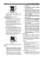
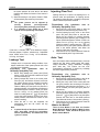
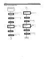
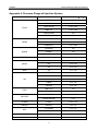
LAUNCH Injector Cleaner & Tester User’s Manual Other product names used herein are for identification purposes only and may be trademarks of their respective owners. LAUNCH disclaims any and all rights in those marks. Trademark Information LAUNCH is a registered trademark of LAUNCH TECH. CO., LTD. (LAUNCH for short) in China and other countries. All other LAUNCH trademarks, service marks, domain names, logos, and company names referred to in this manual are either trademarks, registered trademarks, service marks, domain names, logos, company names of or are otherwise the property of LAUNCH or its affiliates. In countries where any of the LAUNCH trademarks, service marks, domain names, logos and company names are not registered, LAUNCH claims other rights associated with unregistered trademarks, service marks, domain names, logos, and company names. Other products or company names referred to in this manual may be trademarks of their respective owners. You may not use any trademark, service mark, domain name, logo, or company name of LAUNCH or any third party without permission from the owner of the applicable trademark, service mark, domain name, logo, or company name. You may contact LAUNCH by visiting Launch at http://www.cnlaunch.com, or writing to LAUNCH Industrial Park, North Wuhe Avenue, Banxuegang Industrial Park, Longgang Dist., Shenzhen, P.R. China, to request written permission to use Materials on this manual for purposes or for all other questions relating to this manual. Disclaimer z z To take full advantage of the unit, you should be familiar with the engine. All information, illustrations, and specifications contained in this manual are based on the latest information available at the time of publication. The manufacturer resume the right of modify this manual and the machine itself with no prior notice. This unit is made for the purpose of persons who have special techniques and certifications. Safety Precautions Read all service procedures and precautions, installation instructions and equipment operating manuals thoroughly. Failure to observe these precautions, or the improper use of equipment, could result in property damage, serious injury or death. Never allow improperly trained personnel to perform these procedures or operate the equipment. z Copyright Information z Copyright © 2000 by LAUNCH TECH. CO., LTD. All rights reserved. No part of this publication may be reproduced, stored in a retrieval system, or transmitted in any form or by any means, electronic, mechanical, photocopying, recording or otherwise, without the prior written permission of LAUNCH. The information contained herein is designed only for the use of this unit. LAUNCH is not responsible for any use of this information as applied to other units. z z Neither LAUNCH nor its affiliates shall be liable to the purchaser of this unit or third parties for damages, losses, costs, or expenses incurred by purchaser or third parties as a result of: accident, misuse, or abuse of this unit, or unauthorized modifications, repairs, or alterations to this unit, or failure to strictly comply with LAUNCH operating and maintenance instructions. z z z LAUNCH shall not be liable for any damages or problems arising from the use of any options or any consumable products other than those designated as Original LAUNCH Products or LAUNCH Approved Products by LAUNCH. z z General Notice z i Read the operating instructions before attempting to operate the unit. Keep this manual with the unit at all times. Care must be taken as burns can occur from touching hot parts of the equipment or in the engine. Do not operate equipment with a damaged cord or if the equipment has been dropped or damaged until it has been examined by qualified service personnel. Do not hang cords over the edge of the table, bench or counter, or come in contact with hot manifolds or moving fan blades. If an extension cord is needed, a cord with a rated current equal to or greater than that of the equipment should be used. Cords rated for lower current than that of the equipment may overheat. Always unplug equipment from electrical outlet when the machine is not in use. Never pull the cord when unplugging from the outlet. Make sure the equipment cools down completely before putting it away. Loop cord loosely around the equipment when storing. To protect against risk of fire, do not operate the equipment in the vicinity of open container containing flammable liquid (gasoline). Make sure that the unit is in the well-ventilation area when operating the fuel engine. Keep lighted cigarettes, sparks, flames or other ignition sources away from fuel systems at all times. LAUNCH z z z z z z z z z z z Injector Cleaner & Tester User’s Manual Keep hair, clothes, fingers or the other body parts away from the running parts of the unit. In order to avoid electric shock, keep away from the damp part of a working unit and avoid exposing it to the rain. Please operate the unit according to the operation procedures in the manual. Only use the accessories recommended by the manufacturer. Do not switch on the ultrasonic system when there is no ultrasonic detergent in the ultrasonic cleaning chamber. Otherwise, damage to the ultrasonic cleaner can be resulted. Keep the unit well grounded. Provide ventilation through an exhaust gas removal system, ventilation fans or large doors. Carbon monoxide gas, which is odorless and colorless, can cause serious illness, injury or death. Avoid contacting hot surfaces such as exhaust pipes, radiator, etc. Before testing vehicles, put the transmission lever in NEUTRAL position, apply the parking brake, and block the front wheels. ALWAYS WEAR SAFETY GOGGLES. Common used glasses are NOT safety glasses. When disconnecting any connector of the pressurized fuel hose, wrap the connector with towel to prevent the fuel from spurting out. Spurted fuel may cause personal injury or fire. Test liquid is used by the main unit. Detergent is used for on-vehicle cleaning. The ultrasonic cleaning uses specified ultrasonic detergent (It can be replaced by detergent provided together with the unit). Note: Specifying operations that require attention when operating the equipment. Warning: Specifying a possible hazard that could result in damage to the machine or personal injury. PLEASE SAVE THESE INSTRUCTIONS ii LAUNCH Injector Cleaner & Tester User’s Manual Table of Contents Introduction .......................................................................2 Functions.........................................................................2 Features ..........................................................................2 Specifications ..................................................................2 Structure.............................................................................3 Overview..........................................................................3 Control Panel...................................................................3 Installation & Connection..............................................4 1. CNC-602A Installation .................................................4 2. CNC-601A/801A Installation........................................4 3 Ordinary Connection.....................................................4 Operating Procedures ...................................................4 Preparation......................................................................4 Cleaning & testing sequences .........................................5 Tidy up after operating.....................................................5 Operation...........................................................................5 Ultrasonic Cleaning .........................................................5 Uniformity/Sprayability Test .............................................5 Leakage Test ...................................................................7 Injecting Flow Test ...........................................................7 Auto. Test.........................................................................7 On-Vehicle Cleaning......................................................10 Maintenance ................................................................... 11 1. Transporting and Storing ........................................... 11 2. Vulnerable Parts ........................................................ 11 3. Connection Diagram of Driving Board .......................12 4. Troubleshooting & Precautions..................................12 Installation and Adjustment .................................................14 1. Parts List and Structure Diagram of Fuel Path ..........14 2. Parts List and Structure Diagram of Fuel Distributor .15 3. Parts List and Structure Diagram of Fuel Tank ..........15 4. Main Components and Parts .....................................16 Appendix 1: List of Optional Parts ...........................18 Appendix 2: Electrical Diagram ................................20 Appendix 3: Fuel Path Diagram ...............................20 Appendix 4: Pressure Gauge of Injection System ............................................................................................21 1 LAUNCH Injector Cleaner & Tester User’s Manual Special note: This user’s manual is an introduction to the structure, functions, operations, cautions, maintenance and troubleshooting for the proper use of the equipment, LAUNCH Company retain the right of changing product design and specifications, The actual configuration according to the packing list. Specifications Working conditions: z Temperature: -10~+40℃; z Relative humidity: <85%; z Intensity of outer magnetic field: <400A/m; z No naked flame within 2m. Introduction Thank you for purchasing the Injector Cleaner & Tester manufactured by LAUNCH TECH CO., LTD. Developed with the technology of ultrasonic cleaning and fuel pressure control, this equipment is an advanced electromechanical product, which can clean and test injectors by simulating engine working conditions. It can also perform cleaning on the injectors and fuel supply system on vehicle. Specifications: z Main unit power supply: □AC220V±10%, 50/60Hz; □AC110V±10%, 50/60Hz. z Main unit power: 230W(CNC-601A/ 602A) 280W(CNC-801A) z Ultrasonic cleaner power: 100W; z Simulated RPM range: 10 ~ 9990rpm; step: 10rpm; z Time range: 1~9999s; z Pulse width: 0.5~25ms; step 0.1 ms; z Fuel tank capacity: 4700ml(601A/801A) 4000ml(602A) z Dimensions: 400mm×410mm×580mm(602A) 500mm×580mm×1400 mm(601A/801A) z Weight: 27kg(CNC-602A) 95kg(CNC-601A/801A) Functions z z z z z z Ultrasonic cleaning: To perform simultaneous cleaning on several injectors and to remove the carbon deposits on the injector completely. Uniformity/Sprayability test: To test the uniformity of injecting amount of each injector, and to monitor the spraying status of each injector with the help of backlight. This test is also for reverse flush. Leakage test: To test the sealing and dribbling conditions of injectors under system pressure. Injecting flow test: To check the injecting amount of the injector in 15 seconds of constant injection. Auto. test: To test injectors by simulating different working conditions. On-vehicle cleaning: The unit is equipped with various adaptors and couplers that facilitate cleaning on the injectors on vehicle. Features z z z z z Adopting the powerful ultrasonic cleaning technology, The equipment offers complete cleaning to the injectors. Fuel pressure control through microcomputer offers stable pressure control and large adjustable range, which is suitable for all EGI vehicles and can help to achieve automatic cleaning and testing of injectors. With the help of microcomputer control and digital display, The equipment makes possible automatic cleaning, testing injectors and real-time monitoring of the dynamic values. Automatic fuel draining through preset programs for some test items. Test liquid/detergent can also be drained by pushing a button on the control panel after the test. Adopting humanization design can make the system pressure fast restored to the default values. 2 LAUNCH Injector Cleaner & Tester User’s Manual Structure Overview CNC series Injector Cleaner& Tester structure has been shown in Fig.01. Fig.01 1-Return fuel connector; 2- Outlet fuel connector; 3- Top-supply fuel distributor assembly; 4- Measuring cup; 5- Control panel; 6- Socket for pulse signal cable; 7- Pressure gauge; 8- Power socket & Fuse; 9- Power switch 10- Tee joint; 11- Filter; 12- Fluid level switch; 13- Tank; 14- Return hose; 15- Fuel filler; 16- Pump; 17- Fluid level indicator/Fuel draining hose; 18- Sliding curtain; 19- Ultrasonic cleaner; 20- drawer. Note: The illustrations in this manual may be slightly different from the actual product! Control Panel The control panel is shown in Fig.02 (Apart from models signs, the CNC-601A & CNC-602A & CNC-801A control panel is identical.). Fig.02 The control panel can be divided into five areas as shown in the following table: Area Description Item selection Select a function by pressing a[ ]key. The corresponding indicator will light. Parameter selection Select a parameter by pressing a[ ]key. The corresponding indicator will light. After selecting function and parameter, the user can set the parameter value by Parameter setting pressing[◄][ / ►]key. [ ( ►]key is for increasing, [◄]key is for decreasing.) The set value will be displayed on LED screen. System control area below the Item selection & Parameter selection area, which System control control the draining stop and run of the equipment. System pressure control area below the Parameter setting area, which can adjust System pressure control the system pressure by pressing [increase pressure] / [decrease pressure] key. 3 LAUNCH Injector Cleaner & Tester User’s Manual Installation & Connection 1. CNC-602A Installation 1) 2) 3) 4) 5) Move the machine onto the workbench after unpacking and loosen the strips on the outlet hoses. Mount the pulse signal cables onto the socket on the right top side of the machine. Take the two adjusting bolts out from the kit and install them to the press plate on the top of the glass tube. Take the two knurled nuts from the kit and install them on the adjusting bolts. Take the fuel distributor from the kit and install it on the knurled nuts and tighten them with the pressing bolts. Fig.03 1-Outlet hose; 2-Pulse signal cables; 3-Fuel distributor assembly; 4-Adjusting bolts; 5-Knurling nut. 2. CNC-601A/801A Installation 1) Take the pulse signal cables from the box and insert it into the socket on the top right side of the machine and tighten it. 2) Take the pulse signal cables from the box and insert it into the socket on the right upper of the ultrasonic cleaner and tighten them. 3) Take the two adjusting screws out from the box and install them to the press plates on the top of the glass tubes. 4) Take the two knurled nuts from the box and install them on the adjusting screws. 5) Take the fuel distributor from the box and install it on the knurled nuts and tighten them with the pressing screws. Fig.04 1-Outlet hose; 2-Top-supply fuel distributor assembly; 3-Adjusting screw; 4-Knurled nut. 3 Ordinary Connection 1) Take the power cables out from the kit and insert it into the input socket at the bottom of the unit. 2) Take the power cables out from the kit and insert it into the input socket of the ultrasonic cleaner. Operating Procedures 3) Turn on the power switch on the right of the Cabinet. 4) Fill ultrasonic detergent into the ultrasonic cleaning launder so that the needle valve of the injector is covered by the detergent. 5) Connect the injectors with the right couplers. Preparation 1) Remove the injector from the vehicle engine to check the o-rings inside for damage. Replace the damaged O-ring with another same type O-ring to avoid leakage during testing. Put the outside of injectors in gasoline or detergent, and wipe them with soft cloth after cleaning the outside oil sludge carefully. 2) Check the liquid level and refill test liquid when necessary. Fill the test liquid through the filler on the side of the unit and observe the liquid level in the fuel level viewer. In most cases, filled the liquid up to 1/2 of the tank capacity. Note: Test liquid and detergent are provided together with the unit. The test liquid is used for uniformity/sprayability test, leakage test, injecting flow test and auto. test. The mixture of fuel and detergent is used in on-vehicle cleaning. The ultrasonic cleaning uses special injector detergent (or test liquid and detergent that comes with by the unit). 4 LAUNCH Injector Cleaner & Tester User’s Manual to start cleaning. 6) When the time is up, Injector Cleaner & Tester will stop automatically as the beeper rings. 7) Turn off the power of the ultrasonic cleaner, take the injectors out of the launder and wipe them with a dry soft cloth. Get ready for next operation. Cleaning & testing sequences A complete cleaning and testing sequence shown below should be followed: z Ultrasonic cleaning; z Uniformity/Sprayability test; z Leakage test; z Injecting flow test; z Auto. test. Note: Before the injector detergent is added into ultrasonic cleaner, do not turn on the ultrasonic cleaner. Otherwise, damage may be incurred. Select the corresponding parameter and set up according for various tests. For detailed operations, please refer to “Operation” part. Do not dip the pulse signal cables plug and the injector’s body into the detergent. Tidy up after operating Tidy-up should be done after cleaning and testing is completed: z Press [Drain] button to drain the test liquid into fuel tank. z Switch off the power and unplug from the socket. z Drain the injector detergent to its original bottle and then wipe the ultrasonic cleaner with soft cloth. z Clean the Injector Cleaner & Tester control panel with soft cloth. z Drain the test liquid from the tank into a container to avoid volatilization. Store the test liquid in a safe place if it can be used again, or dispose of it in accordance with relevant regulations if it is too dirty. Uniformity/Sprayability Test Uniformity test is to find out if the flow of different injectors meets the requirement or specifications under the same working condition. This test can reflect the comprehensive influences on the injector caused by electrical nature, bore variation and clogging. Sprayability test is to inspect the spraying performance by observing the injectors. Installing and testing procedures for top-supply injectors 1) Choose the fuel distributor stopper (4) from the coupler box and mount a proper O-ring on it. Remember to apply a little lubricating grease on the O-ring. Mount the fuel distributor stopper (4) onto the top-supply fuel distributor. 2) Mount the crescent plate (3) and tighten it with a plate bolt (1). 3) Choose a proper adaptor (5) according to the injector type and mount it to the corresponding coupler under the top-supply fuel distributor. 4) Install the injectors in forward direction (Apply a little lubricating grease on the O-ring.) 5) Install the top-supply fuel distributor and the injector on the fuel distributor supporter with a proper adjustable screw and knurled nuts, and tighten two riffle screws (black). See Fig. 05. 6) Connect the injector pulse signal wire. 7) Before doing this test, press [Drain] button to drain the test liquid from the measuring cup if there is any. 8) Choose [Uniformity/Sprayability test] on the control panel, set corresponding parameters (consult the appendix for pressure setting, consult vehicle manuals for other parameters as needed), and then press [Run] button to start the test. (The equipment can be switched between [uniformity test] and [sprayability test] by pressing [Drain] key when it is running.) 9) When the test is completed, the equipment will auto stop with the ring of the buzzer. Operation Ultrasonic Cleaning Injector Cleaner takes advantage of the penetrability and cavitation impact wave caused by ultrasonic wave traveling through the medium to provide powerful cleaning on objects with complex shapes, cavities and pores, so that the stubborn carbon deposits can be removed from the injectors. Procedures 1) Connect the power supply: connect one end of the power cable to the power socket on ultrasonic cleaner and the other end to power socket. 2) Place the injectors which have gone through surface cleaning in a launder. 3) Add enough injector detergent into ultrasonic cleaner so that the liquid level is about 20mm above the needle valve of injectors. 4) Plug the injector pulse signal wires to injectors respectively then turn on the power switch of the ultrasonic cleaner. 5) Select [Ultrasonic cleaning] in the function column by pressing “ ” key. Select [Timer] in the parameter column, and set the timer (the default time is about 10 minutes) in the value column. Press [Run] button 5 LAUNCH Injector Cleaner & Tester User’s Manual cylinder can be selected by setting the number of the cylinder. ♦ The system pressure can be adjusted by pressing [decrease pressure] / [increase pressure] key when testing. ♦ Keep the fluid level to at least 30 ml while testing. Foam will be produced in the liquid during injection. In order to prevent spillover, set the related parameter with reference to the following formula :Pulse width(ms)×time(s)× speed(rpm) / 120≤18000 ♦ This is for checking the uniformity of each cylinder. Injecting difference of all injectors on one vehicle should be kept within 2% during uniformity testing. ♦ During operating, the user can select parameter, such as RPM or PW, and then press[◄]or[►] key to achieve the status of the simulation. ♦ Good injectors may have identical injecting angle, uniform spraying but no jet. Otherwise, replace the injector. ♦ In the sprayability test, a special electrical parameter--the minimum injection pulse width of injector--can be tested, to compare the injectors on the same engine. That is to set cylinder No., start the test from minimum injection pulse width, and then gradually increases the pulse width till the injector starts injection (observed with the help of backlight). The value set at this moment is the minimum injection pulse width, so the difference of minimum injection pulse width among these injectors could be observed. Reverse flush Injector Cleaner & Tester can also perform reverse flush by connecting with flush-back adaptor at [Uniformity/Sprayability test] mode. Reverse flush is a way to clean the injectors with the test liquid flowing from the outlet to the inlet of the injector. Reverse flush may remove the dirt inside the injector or the injector Strainer (Only for the top fuel supply injector). Fig. 05 for fuel top-supply injector 1-Plate bolt; 2-Riffle screw; 3-Crescent plate; 4-Fuel distributor stopper; 5-Adapter for fuel top-supply injector; 6-Injector;7-Knurled nut; 8-Adjustable screw Installing and testing procedures for side-supply injectors 1) Choose proper couplers for side-supply injectors (3) and proper O-rings, and mount them together. (Remember to apply a little lubricating grease.) 2) Mount the injectors on the couplers and install them onto the side-supply fuel distributor. 3) Mount the cross plate (1) and tighten it with bolts. 4) Mount the fuel distributor and injectors onto the fuel distributor supporter, and tighten them with two riffle screws (black). See Fig. 06. 5) Connect the injector pulse signal wire. 6) Before doing this test, press [Drain] button to drain the test liquid from the measuring cup if there is any. 7) Select [Uniformity/Sprayability test] on the control panel, set the corresponding parameters and press [Run] button to start the testing. (when it is running press the [ ]key then press [run] key the system pressure will come back to the default pressure value When the function of item section is working) 8) When the testing is over, Injector Cleaner & Tester will auto stop at the ring of the buzzer. Procedures: 1) Choose a reverse flush coupler and proper O-ring, and mount them under the fuel distributor. 2) Install the injectors in reverse direction (outlet upward, and inlet downward). 3) Choose a proper coupler according to the shape of the injector and put it under the injector. 4) Install the fuel distributor and the injector on the fuel distributor supporter with a proper adjustable screw and knurled nuts, and tighten two riffle screws (black). See Fig. 07. 5) Connect the injector pulse signal wire. 6) Set parameter, and press [Run] button to start cleaning(Injector Cleaner & Tester can switch between reverse flush by pressing [Drain] key when it is running press the [ ]key then press run key Fig. 06 1-Cross plate; 2-Fuel side-supply injector; 3- Coupler for fuel side-supply injector; 4,5-O-ring; 6-Side-supply fuel distributor Note: ♦ While testing, Injector Cleaner & Tester can drain fuel by pressing [Drain] key. At default, solenoid valve is set at the closed state. Uniformity test can be done at this state. When [drain] key is pressed, solenoid valve will drain oil. ♦ The default cylinder number of the system is 0, which means that all injectors are working when Injector Cleaner & Tester is running. A specific 6 LAUNCH Injector Cleaner & Tester User’s Manual the system pressure will come back to the default pressure value When the function of item section is working). 7) When the cleaning is over, Injector Cleaner & Tester will automatically stop at the ring of the buzzer. Note: ♦ The system pressure can be adjusted by pressing [decrease pressure]/[increase pressure] key when performing reverse flush. ♦ It is advisable to press [Drain] key to avoid spillover of test liquid during reverse flush. Injecting Flow Test Injecting flow test is to check if the injecting flow in 15 seconds meets the specifications for injecting amount. The deviation reflects the wear or clogging in the injector, instead of electrical parameter variation. Procedures (For installation Uniformity / Sprayability Test): 1) 2) Fig. 07 1-Plate bolt; 2-Crescent plate; 3-Fuel distributor stopper; 4-Reverse adaptor; 5-Injector; 6-Knurled nut; 7-Adjustable screw; 8-Riffle screw; 9,10,11-O-ring; 12-Fuel distributor; 13-O-ring; 14-Couplers. 3) refer to Before this test, press [Drain] button to drain the test liquid from the measuring cup if there is any. Choose [Injecting flow test] mode on the control panel, and press [Run] button to start the test. Adjust the fuel pressure by pressing [decrease pressure]/[increase pressure] key according to the injector specification(Injector Cleaner & Tester can switch between injecting flow test by pressing [Drain] key when it is running press the [ ]key then press run key the system pressure will come back to the default pressure value When the function of item section is working). When the test is over, Injector Cleaner & Tester will stop automatically at the ring of the buzzer. Auto. Test Leakage Test Auto. test contains all above-mentioned tests (15-second injecting test, idle speed, middle speed, high speed, varying acceleration, varying deceleration, changing pulse width test). This function can test more comprehensive performance of injectors by simulating the various engine working conditions. Leakage test is to inspect the sealing conditions of the injector needle valve under system pressure and to find out if the injector is dribbling. Procedures (For installation refer to Uniformity/ Sprayability Test): 1) Before doing leakage test, please press [Drain] button to drain the rudimental residual test liquid from the measuring cup. 2) Select [Leakage test] mode on the control panel. Press [run] key, the machine will work. At this time the system pressure can be adjusted by pressing [decrease pressure]/[increase pressure] key to observe dribbling from the injector the pressure is adjusted preferably 10% higher than manufacturer’s specifications(Injector Cleaner & Tester can switch between leakage test by pressing [Drain] key when it is running press the [ ]key then press run key the system pressure will come back to the default pressure value When the function of item section is working). 3) When the test is over, the equipment will automatically stop and the buzzer will ring simultaneously. Note: ♦ In general the drip of the injector should be less than 1 drop within 1 minute (or in accordance with the specifications). The default time of the system is 1 minute. Procedures (For installation Uniformity / Sprayability Test): 1) 2) 3) 4) refer to Before the test, press [Drain] button to drain all the test liquid in the measuring cups if there is any. Select [Auto. test] mode on the control panel and set up the pressure value according to the injector specifications, select the test mode (mode 1, 2, or 3 are all available), and then press [Run] button to start the test. Adjust the fuel pressure by pressing [decrease pressure]/[increase pressure] key when testing or press the [ ]key then press run key the system pressure will come back to the default pressure value When the function of item section is working).. When the test is over, Injector Cleaner & Tester will auto stop at the ring of the buzzer. What’s the Model? There are three Models in the Auto. test function Model I Model II & Model III, Model I & Model II shown in the flow chart below, the Model III equal to the Model I add the Model II. 7 LAUNCH Injector Cleaner & Tester User’s Manual Mode I for Automatic Test Start the pump and adjust system pressure to appropriate value. A Injecting for 15sec Observe the injecting angle and spraying condition Observing for 30s Watch the blocking and dripple. RPM: 4500 Pulse width: 5 ms Times: 1700 Observing for 30s Draining for 30s Draining for 30s RPM: 650r/min Pulse width: 3ms Times: 2000 Observe the medium speed condition Observe condition the RPM: 6000 (max. rpm of multi-point injection Pulse width: 3 ms Times: 2500 idle Drain the fuel after medium speed test Observe the high speed condition Observing for 30s Observing for 30s Draining for 30s Draining for 30s Drain the fuel after test at idle End A 8 To drain the fuel after high speed condition LAUNCH Injector Cleaner & Tester User’s Manual Mode II for Automatic Test Set pressure value and start the pump to the desired pressure Various speed test (3 cycles). Accelerate from 350rpm to 6000rpm (step: 50rpm). Decelerate from 6000rpm to 350rpm (step: 50rpm). The duty ratio decreases by 1/3 each time under certain speed. Various speed test (3 times) Accelerate from 350rpm to 6000rpm (step: 50rpm) Duty ratio decreases by 1/3 each time under certain speed Decelerate from 6000rpm to 350rpm (step: 50rpm) Duty ratio decreases by 1/3 each time under certain speed Watch for 30s Draining for 30s Drain fuel after various speed test. End 9 LAUNCH Injector Cleaner & Tester User’s Manual Connecting On-Vehicle Cleaning The hose line connection of the engine with return hose is shown as in Fig.09. 1) Disconnect the connections of fuel supply hoses (C、 D) and fuel return hoses(A、B) of the engine fuel system( wrap the connector with towel when disconnecting the connector). Choose proper connectors and connect them to the B end and C end separately, and then connect the other ends to corresponding return hose and outlet hose of the unit. See Fig.09. 2) Connect the disconnected other ends (A、D) with proper hose, or remove the fuel pump fuse, or disconnect the power cable of engine fuel pump. After the engine has been in operation for a period of time, its fuel flow may be blocked or become un-smooth owing to buildup of dust and impurities in fuel channel. In addition, the carbon deposits and gum made by combustion can easily adhere to the injectors, inlet and outlet ports, inlet and outlet hoses, throttle and combustion chamber. So the fuel supply system, combustion chamber and injectors of the engine must be cleaned on a timely basis. On-vehicle cleaning is a solution that can save your time and labor. Procedures 1) Please check if there is test liquid or detergent inside the fuel tank before on-vehicle cleaning. If test liquid is in the tank, replace it with detergent. The detailed procedure to be followed: remove the level indicator on the left of the main unit, and drain the test liquid inside fuel tank into a container. If the drained test liquid contains lots of impurities and can not be reused, please dispose it in the proper way and fill with new test liquid. If the drained test liquid is clean, please store it for later using. 2) Blend the detergent with the fuel at a certain ratio, and fill the mixture into the fuel tank. (Consult the user’s manual of detergent for blending ratio.) Refer to the following table for filling amount, as shown in the following table: No. of cylinders Amount 4 cylinder about 800~1000ml Fig.09 1-CNC Injector Cleaner & Tester; 2-Engine; 3- Fuel-return hose from engine; 4- Fuel-inlet hose to engine; 5-Auto filter; 6-Engine fuel supply hose; 7-Engine fuel return hose; 8- Auto fuel pump; 9-Auto tank Without return hose connecting: The hose line connection of the engine without return hose is shown as in Fig.10. 1) Disconnect the fuel supply hoses (E, F) of engine fuel system (wrap the connector when disconnecting the connector), and then choose a proper connector and connect it to the E end. Reconnect the fuel outlet hose of the unit well and make the fuel return hose hanging. See Fig.10. 2) Stop the other end of the disconnected end (F) with a proper stopper, (use when the fuel pump has the fuel return function only) or remove the fuse of fuel pump or disconnect the power cable of fuel pump. 6/8 cylinder about 1500ml 3) The connection of engine fuel pipes has been shown in “Connecting” below. 4) Choose [On-vehicle cleaning] function on the control panel, and set the time and press [Run] button to start the test, then start the engine with park gear. 5) Refer to specifications required by various vehicle types to adjust system pressure by pressing [decrease pressure]/[increase pressure] key(The user can press the [ ]key then press run key the system pressure will come back to the default pressure value When the function of item section is working).Press [Stop] button at any time to stop the cleaning. Fig.10 1-CNC Injector Cleaner & Tester; 2-Engine; 3-stopper; 4- Fuel-inlet hose to engine; 5-Auto tank; 6-Auto filter; 7- Engine fuel supply hose; 8-Auto fuel pump; Fig.08 1- Fuel-return connector; 2- Fuel-return hose from engine; 3-Fuel-inlet hose to engine 10 LAUNCH Injector Cleaner & Tester User’s Manual should be put in well-ventilated area. Make sure the temperature is within -10℃~ +40℃. The unit has been well grounded for safety operation. Please confirm that the power socket is also well grounded. Tidy up after on-vehicle cleaning 1) After the on-vehicle cleaning is completed, turn off the Auto Ignition Switches restitute the link of the Auto fuel hoses then start the Auto to check the leakage of Auto fuel system. 2) At last please clean the fuel tank and hose line with test liquid (if there is residual detergent inside fuel tank, please.). The detailed procedure is shown as follows: drain the liquid inside the fuel tank out and dispose it on the clean degree, and then fill little test liquid and turn on the power. Select “Leakage test” item and press [RUN] key to run the unit for about 2∼3 minutes. When the unit stops, drain the test liquid from fuel tank and dispose the liquid as related regulation. 3) Tidy up and make preparation for the next cleaning. B. Warning! If an extension cord is used, the rated current should be equal to or greater than that of the equipment. 2. Vulnerable Parts Vulnerable Parts List Parts no. 104130016 Note: 1) When cleaning, care must be taken as the detergent is inflammable. Prepare for a fire extinguisher. 104130017 199010019 2) Be sure that all hose lines are well connected and there is no leakage on the hose lines before performing cleaning. 199010035 103100090 Maintenance 103260003 1. Transporting and Storing D. E. B. ¢40.2*15*3 CNC-601A/602A: 6PCS CNC-801A: 8PCS 4L 1PCS MFE-101 325 ml 2PCS CNC-602A 1CS CNC-601A/801A: 3CS 1 PCS 1 PCS To see the Main Components and Parts list SH20 Filter Pump filter Note: Impurities can be built up in the test liquid after being used for a period of time. Do not use contaminated test liquid, otherwise, injector and fuel pumps can be blocked. Drain the test liquid by removing the level indicator on the left of the main unit. It is better to clean the fuel tank with a little test liquid before the tank is filled in with new liquid. Replacing O-ring Replace the O-ring when it is deformed in order to avoid leaks during cleaning or testing. Store only in dry area and keep away from water before the unit is unpacked. Store the machine in well-ventilated area and do not expose it to direct sun shine or rain. Replacing Filter & pump filter The filter tends to accumulate impurities after a period of using. Replace the filter periodically to ensure Injector Cleaner & Tester work normally. Select the [Leakage test] item to check if there is leak in the connector after 3. Installation Environment A. ¢40.2*22*3 Test liquid and detergent are shipped together with the unit. The test liquid is used in all tests except for on-vehicle cleaning, for which the mixture of fuel and detergent is used (the blending ratio of detergent and fuel is 1:4).The ultrasonic cleaning uses special ultrasonic detergent (or test liquid and detergent attached by the unit). Before being packed, the liquid inside the fuel tank should be drained completely to avoid overflowing as transporting. Move only by hand or lift with soft belt. No package no lifting tools or long-distance transportation. To prevent the unit from shocking and knocking, make sure it is on the base seat and in the packing case during transportation. Firstly pack the unit with the matter similar with plastic strip and add the filling material (such as foam or sponge, etc.) between the unit and packing case to avoid scratching the surface when the unit shakes. Make sure that the maximum incline angel does not exceed 45°. Do not place the unit up-side-down. 2) Storing A. Number Test Liquid and Detergent 1) Transporting B. C. Fast connector (female) Specifications Various “O” ring It is advisable to transport the unit by hand or forklift. A. Name Upper seal gasket for glass tube Lower seal gasket for glass tube Test liquid Detergent Keep a distance of no less than 200mm between the unit and any wall or other substance. The unit 11 LAUNCH Injector Cleaner & Tester User’s Manual replacement. I Replacing fuel pump filter I Replacing filter The fuel pump filter has been fixed in the pump bottom, if you want exchange it you must remove the back board and remove the sealing cover for fuel pump then take out fuel pump sleeve, pull out the pump filter and exchange a new one. The equipment filter has been fixed behind the main unit, if you want exchange it you must remove the back board and loose the clamp, take the filter out and exchange a new one. Filter Tlamp Fig.11 Fig.12 1-pump; 2- Sealing cover for fuel pump; 3- Fuel pump sleeve; 4-Pump filter; 5- Cross bulged screw; 6-Tuel tank. 3. Connection Diagram of Driving Board Fig.13 Description: No. 1 2 3 4 5 6 7 Part Name Insert piece for power supply marked “-” Insert piece for fuel pump marked “-” Insert piece for fuel pump marked “+” Insert piece for power supply marked “+” Socket for level switch Power socket Extension socket No. 8 9 10 11 12 13 Part Name Socket for solenoid valve control cable Relay for solenoid valve Fuse for solenoid valve Insert piece for power supply marked “+” Socket for injector pulse signal cables Insert piece for power supply marked “-” minutes, slightly turn the overflow valve with inner 4. Troubleshooting & Precautions Troubleshooting 1. The unit does not correspond when it is switched on. Check the fuse at lower right side of the unit and replace it (AC 250V/5A) if it is damaged or broken. 2. There is leakage in the fuel distributor coupler. Check the o-rings and replace it if it is damaged or unfitted. Do not tighten the two riffle screws too tightly; otherwise, it may cause leakage. 3. The fuel pressure drops slowly. The fuel pressure can not drop to zero within 1~2 hexagonal spanner counterclockwise. 4. The buzzer rings continually when there is no fuel pressure. The machine has fuel-lack warning function and it will ring when the liquid in the fuel tank is lack, and then automatically switch off the fuel pump and injectors and returns to the stop state. Supply the detergent or test liquid to stop ringing. At this time, pressing [RUN] key is 12 LAUNCH Injector Cleaner & Tester User’s Manual necessary to rerun the fuel pump and injectors. 5. Draining the test liquid in glass tube thoroughly requires pressing the [Drain] key more times. The solenoid valves will stop automatically after 15 seconds and it is necessary to drain more times if there is more liquid. 6. Malfunction code displaying E001. The malfunction code of E001 is displayed when the level inside fuel tank is lower than that of the required level. At this time, the buzzer will ring to remind user to supply fuel. If this situation appears during running process, the machine will stop the fuel pump ten seconds later and make “RUN” indicator is on the flashing state. After the liquid is up to the required specification(Press “Drain” key to drain the liquid into the fuel tank to resume the liquid level if there is lots of liquid, otherwise, supply the liquid.), the buzzer will stop ringing. If you press [RUN] key, the machine will continue to run the interrupted work. Precautions 1) Do not place anything on the control panel to prevent from breaking the measuring cup because it is made from vulnerable. 2) Do not disconnect hose before the system pressure reaches “0”. 3) Always ensure that the provided power supply is well contacted with ground safely. 4) The unit is designed with warning function. When the level switch checks the liquid inside the tank less than the lowest line, the unit will utter the warning sound and meanwhile stop the fuel pump and injectors automatically, and then the unit returns to the stop state. The unit will stop warning until the liquid is supplied enough, at this time pressing the “RUN” key will run the unit again. 5) Clean the control panel in time and Keep the pulse signal cable away from the liquid. Warning! Unauthorized repair may cause the extension of faulty area of the unit, which will bring trouble to general repair. Under the state of turning on the power, the electrical system inside the unit contains the factor causing danger. Failure to comply with these instructions could result in death or serious injury. 13 LAUNCH Injector Cleaner & Tester User’s Manual Installation and Adjustment 1. Parts List and Structure Diagram of Fuel Path Injector To fuel gauge To fuel tank To fuel pump To fuel tank Fig.14 Parts list of the fuel path Item 1 2 3 Part No. 103250008 103250002 103250029 103250013 103250014 103250015 103250016 4 5 6 7 8 9 103250003 103250030 103250004 103250031 102040194 107040104 Z205010263 Z 205010084 104130016 Part name Pressing screw 2 6-cylinder distributor 8-cylinder fuel distributor Top-supply connector 1 Top-supply connector 2 Swiss thread adaptor for fuel top-supply injector Coarse thread adaptor for fuel top-supply injector 6-cylinder upper plate 8-cylinder upper plate 6-cylinder lower seat plate 8-cylinder lower seat plate CNC-602A keys film CNC-601a/801a keys film Driving board(PCA) Control board(PCA) Upper O-ring Item 10 11 13 Part No. 103200350 104130017 102240040 102240041 104110009 Part name Inner hexagonal thread sleeve Lower O-ring Solenoid valve,AC220V Solenoid valve,AC110V Glass tube 14 105020085 Navigator connector cable 15 103260003 Gasoline filter 103240284 103200705 202010019 102990017 102990023 102990020 102990021 103250007 103240050 T-type blocker for CNC-602A T-type blocker for CNC-601A/801A Quickly connect hose Backlight for CNC-602A .AC110V Backlight for CNC-602A .AC220V Backlight for CNC-601,A/801A AC110V Backlight for CNC-601,A/801A AC220V Knurled nut Quick connector(male) 12 16 17 18 19 20 14 LAUNCH Injector Cleaner & Tester User’s Manual 2. Parts List and Structure Diagram of Fuel Distributor Parts list of fuel distributor: Item Part No. Part name 1 103250002 6-cylinder fuel distributor 2 202010019 Quick connection hose 3 103250003 Upper plate 4 103250004 Lower plate 5 103240050 Quick connector (male) Fig.15 Item 6 7 8 9 Part No. 103240015 103240050 103240195 103260003 10 104120026 Part name Tower connector Quick connector Copper hose, Φ2.5 Gasoline filter Return fuel viewer for on-vehicle cleaning 3. Parts List and Structure Diagram of Fuel Tank Item 1 2 3 4 Parts No. 102990030 X103200691 X103200690 No coding Parts Name Fuel pump Sealing cover for fuel pump Fuel pump sleeve Tank filter 5 No coding 6 X103010124 7 X103010228 Screw M3x12 8 102100022 Vertical level Switch 9 104120026 PU hose for fuel level Fuel tank Cross bulged screw,GB818-85 M4 x 12 管 管A Fig.16 15 LAUNCH Injector Cleaner & Tester User’s Manual 4. Main Components and Parts Item Parts No. Parts Name Number 201020068 6-cylinder fuel distributor package 1 set 201021493 8-cylinder fuel distributor package 2 sets 103250002 6-cylinder fuel distributor 1 103250029 8-cylinder fuel distributor 2 3 103250005 Crescent plate 3(4) Tightening the distributor stopper fuel 4 103250006 Press plate bolt 3(4) Tightening the distributor assembly fuel 5 103250014 Adaptor 2 for fuel top-supply injector 6 (8) For some injectors 6 103250028 Stopper distributor 6(8) Installation of various of top-supply injectors and accessories 7 103230107 Adjusting pole 2 for reverse flush 2 Length: 80mm 8 103250007 Knurled nut 2 Installation between the fuel distributor assembly and upper press plate. 9 103250008 Pressing screw 2 2 10 103250013 Adaptor 1 for fuel top-supply injector 6(8) Bore: Φ10.5 11 103250015 Swiss thread adaptor for fuel top-supply injector 6(8) Be used for connecting swiss thread injector (M10×1). 12 103250016 Coarse thread adaptor for fuel top-supply injector 6(8) Be used for connecting coarse thread injector ( M12). 13 104990012 BUICK injector adaptor 6(8) Be used for the connection of BUICK injector. 14 103250018 Hexangular stopper 5(7) Be used when the amount of injectors is less than 6. 1 2 for fuel Specifications Remarks For the Installation and fixation of injector Distributing the fuel from the quick connector to each injector top-supply Tightening the distributor assembly 16 fuel LAUNCH Injector Cleaner & Tester User’s Manual Item Parts No. Parts Name Number Specifications 15 105020217 pulse signal connection cable 1 10 Be used for the connection of special injector, T=0.5 16 105020218 pulse signal connection cable 2 10 Be used for the connection of special injector, T=0.8 103260037 17 103200583 18 Ultrasonic cleaner assembly 103250017 Reverse flush adaptor 101020131 6-cylinder Injector pulse signal cables 19 Including: main unit, bracket and cover,AC220V 1 Including: main unit, bracket and cover,AC220V 6(8) Provide the injectors pulse signal 1 105020083 8-cylinder Injector pulse signal cables 20 199010019 Test liquid 1bottle 21 307030024 Detergent 2 bottles 22 206010154 On-vehicle cleaning kit 23 104130022 O-ring 9 Φ32.5×2.65 24 104130033 O-ring 18 Φ23.6×1.8 25 104130032 O-ring 9 Φ15×2.65 26 104130024 O-ring 18 Φ23.6×2.65 27 104130023 O-ring 24 Φ20×2.65 1set Note: Amount in the parenthesis is CNC-801A allocation amount. 17 4L MFE-101, 325mL Including: a set of adaptor and 2 fuel hoses; Optional Parts to CNC-602A Remarks LAUNCH Injector Cleaner & Tester User’s Manual Appendix 1: List of Optional Parts No. Part No. Part Name Number 1 103250137 Aux. Support assembly for side-supply injector 1 2 103250133 Adaptor B for reverse flush 6(8) Inner bore: Φ16.2, Specification of the matched o-ring:15×2.65 3 103250132 Adaptor A for reverse flush 6(8) Inner bore: Φ18, Specification of the matched o-ring:17×2.65 4 103250130 Adaptor for fuel top-supply Australia injector 6(8) Bore of connected hose: Φ8 5 103250026 Nissan Maxima adaptor 6(8) Bore: Φ26.3 6 103250025 Cadillac adaptor 6(8) Bore: Φ25.5 7 103250024 Nissan 324/Daewoo adaptor 6(8) Bore:Φ22.3 8 103250023 Mazda 929 adaptor 6(8) Bore: Φ25.9 9 103250022 Previa adaptor 6(8) Bore: Φ23.5 10 103250021 Bluebird adaptor 6(8) Bore:Φ26 11 103250020 Chevrolet adaptor 6(8) Injector bore:Φ29 Specifications of O-ring: Φ32.5×2.65,Φ23.6×2.65 12 103250012 Cross plate 3(4) Forward cleaning for fuel side-supply injectors. 13 103250011 Hexagonal underlay for reverse flush 6(8) Bore:Φ11 Reverse flush for fuel side-supply injectors. 18 Specifications M20 Remarks LAUNCH Injector Cleaner & Tester User’s Manual No. Part No. Part Name Number 14 103250010 Hexagonal underlay for reverse flush 6(8) 15 103230060 Stopper for GM fuel distributor 1 16 103230059 GM fuel distributor assembly 1 Bore of o-ring:Φ30×2.65, Φ12.5×2.65 17 103230058 Chevrolet Cavalier adaptor 2 Bore: Φ23 18 103230051 Nissan single-point adaptor for fuel top-supply 2 Φ5 19 103230050 Ford single-point base seat 2 Inner bore: Φ14 20 103230049 Single-point aux. Bracket 1 21 103230048 Single-point Aux. base seat 1 22 103230041 Reverse-flush base seat for Australia injector 6(8) Bore: Φ11.5 23 103230040 Ultrasonic base seat for Zhonghua injector 6(8) Bore: Φ14 24 103230039 Reverse-flush base seat for Zhonghua injector 6(8) Bore: Φ14 25 103230038 Reverse-flush adaptor for Zhonghua injector 6(8) Bore: Φ14 Note: Amount in the parenthesis is CNC-801A allocation amount. 19 Specifications Bore: Φ14 Reverse flush for fuel side-supply injectors. G1/4” Remarks LAUNCH Injector Cleaner & Tester User’s Manual Appendix 2: Electrical Diagram 2 3 M 4 T2 T 1 T 3 T4 J2 JA J3 8 5 J 11 J5 J4 J1 7 T6 T5 6 L N GND L N GND 1-Pump; 2-Drive board; 3-Control panel; 4-Level switch; 5-Solenoid valve; 6-Injector; 7-Switching type power supply;8-Backlight; 9-Power switch; 10-Fuse; 11-Socket for power supply; 12-Operating panel. Appendix 3: Fuel Path Diagram 1 11 2 9 10 A 3 8 4 7 B C D 5 6 1-Fuel distributor; 2-Injector; 3-Mesuring tube; 4-Solenoid valve; 5-Fuel tank; 6-Level switch; 7-Fuel pump; 8-Filter; 9-return hose connector; 10- Tee joint; 11-Pressure gauge; A-Injector pulse signal cables;B-Control cables for solenoid valve; C-Control cables for level switch; D-Power control cables for fuel pump. 20 LAUNCH Injector Cleaner & Tester User’s Manual Appendix 4: Pressure Gauge of Injection System COMPANY MODEL SYSTEM PRESSURE (MPa) TOYOTA 3.0 0.284 PREVIA 0.27—0.33 LEXUS 300 400 0.265—0.304 CAMRY 3.0 0.265—0.304 LAND CRUISER 0.30 COROLLA 0.27—0.31 ACCORD 2.0 2.2 0.285 CIVIC 1.5L 0.255—0.285 LEGEND 3.2L 0.27—0.304 BLUE BIRD 0.25 MAXIMA 0.25 300EX 0.206—0.255 V63000 0.35 323 0.20—0.22 626 0.25—0.29 929 0.25—0.29 528 0.27—0.29 BUICK CENTURY 0.29—0.33 BUICK PARK AVENUE 0.29—0.33 CADILLAC 5.7 0.29—0.33 LUMINA 0.23—0.30 CORSICA 0.25—0.30 TEMPO 2.3L 0.28 LINCOLN TOWN 0.206—0.308 CHEROKEE 213 0.273 CHRYSLER DODGE 3.3L DODGE CARAVAN 0.337 HYUNDAI SONATA 0.265—0.275 DAEWOO DAEWOO 0.28—0.30 6 CYLINDER 0.24—0.27 5, 4 CYLINDER 0.45—0.50 VOLKSWAGEN JETTA 0.27—0.29 VOLVO VOLVO 0.23—0.30 TOYOTA HONDA NISSAN MITSUBISHI MAZDA BMW GM FORD AUDI 21 LAUNCH Warranty THIS WARRANTY IS EXPRESSLY LIMITED TO PERSONS WHO PURCHASE LAUNCH PRODUCTS FOR PURPOSES OF RESALE OR USE IN THE ORDINARY COURSE OF THE BUYER’S BUSINESS. LAUNCH electronic product is warranted against defects in materials and workmanship for one year (12 months) from date of delivery to the user. This warranty does not cover any part that has been abused, altered, used for a purpose other than for which it was intended, or used in a manner inconsistent with instructions regarding use. The exclusive remedy for any automotive meter found to be defective is repair or replacement, and LAUNCH shall not be liable for any consequential or incidental damages. Final determination of defects shall be made by LAUNCH in accordance with procedures established by LAUNCH. No agent, employee, or representative of LAUNCH has any authority to bind LAUNCH to any affirmation, representation, or warranty concerning LAUNCH automotive meters, except as stated herein. Disclaimer THE ABOVE WARRANTY IS IN LIEU OF ANY OTHER WARRANTY, EXPRESSED OR IMPLIED, INCLUDING ANY WARRANTY OF MERCHANTABILITY OR FITNESS FOR A PARTICULAR PURPOSE. Order Information Replaceable and optional parts can be ordered directly from your LAUNCH authorized tool supplier. Your order should include the following information: 1. Quantity 2. Part number 3. Item description Customer Service If you have any questions on the operation of the unit, please contact us: Tel: 400-830-5166, Fax: +86-755-84528830, E-mail: [email protected]. If your unit requires repair service, return it to the manufacturer with a copy of the sales receipt and a note describing the problem. If the unit is determined to be in warranty, it will be repaired or replaced at no charge. If the unit is determined to be out of warranty, it will be repaired for a nominal service charge. Send the unit pre-paid to: Injector Cleaner & Tester User’s Manual Attn: Overseas Department LAUNCH Industrial Park, North Wuhe Avenue, Banxuegang Industrial Park, Longgang Dist., Shenzhen, Guangdong Province P.R. China