1
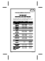
PROGRAMMING MANUAL
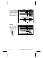
120 SELECT
CONTROLLER SOFTWARE
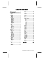
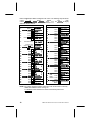
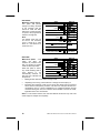
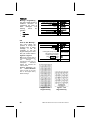
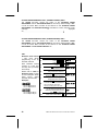
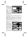
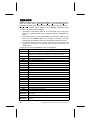
This manual contains only the programming instructions for the
120 Select Controller used on the vending machines listed below.
Please refer to your service manual for other information.
VENDOR
MODEL
SOFTWARE
COMBO 3/6
3155, 3155A
67185-8
SNACK
MART VI
3157, 3157A
3158, 3158A
3159, 3159A
67185-8
SM5700
3160, 3160A
67185-8
CF1000
3162, 3162A
67210-5
3168, 3168A
3169, 3169A
3170, 3170A
67185-8
67217-10
67257-3
3183, 3183A
3184, 3184A
3185, 3185A
67231-3
RFS
CHILLED
RFS
AMBIENT
JAN 2007
67185-8
RSQF 2000
3175, 3175A
3176, 3176A
3177, 3177A
67185-8
FF2000
3182, 3182A
67209-5
SC100
3187
67185-8
67212-1
67209-5
DUAL ZONE
SNACK
3195, 3195A
3193, 3193A
67232-7
67234-3
SINGLE ZONE (SZF)
/DUAL ZONE (DZF)
(DZF) FOAMED
SNACK
3207, 3207A
3208, 3208A
67256-3
67234-3
P/N 4212619 • H
TABLE OF CONTENTS
SERVICE MODE ............... 1
Service Mode Button ...................................1
Keypad ..........................................................1
Display...........................................................1
MENU 1......................................2
DIAGNOSE ....................................................3
MOTORS ........................................................... 4
CONFIG ............................................................. 4
ACCOUNT .....................................................4
HIST SALES ...................................................... 5
HIST COUNT ..................................................... 5
RES SALES....................................................... 5
RES COUNT ...................................................... 5
RDR SALES ...................................................... 6
2ND VEND......................................................... 6
SET RANGE ...................................................... 6
RANGE CASH ................................................... 7
RANGEVENDS.................................................. 7
CLEAR............................................................... 7
COIN ..............................................................7
CPO ................................................................... 8
TUBE FILL......................................................... 8
UNCON ACCP................................................... 8
EXACT CHNG ................................................... 9
TIME ................................................................ 29
DATE ............................................................... 29
MONTH............................................................ 29
YEAR ............................................................... 29
DAYLIGHT....................................................... 29
SHUTDOWN / ADVANCED POWER
MANAGEMENT .......................................... 30
OFF (ON) ......................................................... 31
TIME ................................................................ 32
DAY ................................................................. 33
RANGE ............................................................ 34
TEMPERTURE............................................ 34
DEGREE F - DEGREE C ................................. 35
SENSOR1 ........................................................ 35
ON/OFF.................................................................... 35
SET POINT .............................................................. 36
DELTA ..................................................................... 38
DEFROST ................................................................ 39
DURATION ......................................................... 40
PERIOD .............................................................. 40
DELAY................................................................ 41
MANUAL ............................................................ 41
H/S ........................................................................... 42
LEVEL ................................................................ 42
RANGE ............................................................... 43
TEST ..............................................................9
SENSOR2 ........................................................ 43
SENSOR3 ........................................................ 43
SENSOR4 ........................................................ 43
PRIORITY ........................................................ 43
TEST VEND....................................................... 9
TEST RELAY................................................... 10
DISCOUNT .................................................. 45
MENU 2....................................11
SERV/CONTR..............................................11
PRICE ..........................................................13
ITEM(S)............................................................ 13
COMBO ........................................................... 14
OPTIONS .....................................................15
BILL SCROW .................................................. 15
FORCE VEND.................................................. 15
MAX CHANGE................................................. 16
MULTI VEND ................................................... 16
FREE PROD .................................................... 17
PROMO VEND.............................................17
SENSOR1 ................................................................ 44
SENSOR2 ................................................................ 45
OFF (ON) ......................................................... 46
TIME ................................................................ 46
DAY ................................................................. 46
RANGE ............................................................ 46
VALUE............................................................. 46
AUTOREINST ............................................. 47
ON (OFF) ......................................................... 47
RANGE ............................................................ 47
COUPN/TOKN............................................. 47
COUP VALUE.................................................. 48
COUP RANGE................................................. 48
TOKN VALUE.................................................. 49
TOKN RANGE ................................................. 49
OFF/ON ........................................................... 17
RANGE ............................................................ 17
CAN/BOTTLE.............................................. 50
DEFAULT ........................................................ 18
MESSAGES..................................................... 21
OPTIONS......................................................... 21
OPTIC.......................................................... 51
CONFIG .......................................................18
MENU 3....................................23
POS/AUX .....................................................24
POS ................................................................. 24
LANGUAGE..................................................... 25
AUX ................................................................. 28
OFF (ON) ......................................................... 50
RANGE ............................................................ 50
DEPTH............................................................. 51
OFF - ON ......................................................... 52
RANGE ............................................................ 53
DEX/UCS........................ 54
TIME/DATE..................................................28
ii
COMBO • SMVI • SM5700 • RFS • RSQF • SC100 • DZ • P/N 4212619
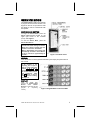
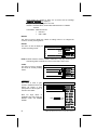
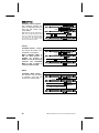
SERVICE MODE
The SERVICE MODE is used by the operator
to program and service the machine. The
keypad is used as an input device while
the display is used to communicate with
the operator.
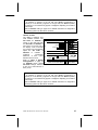
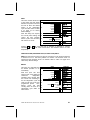
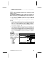
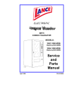
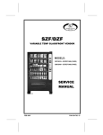
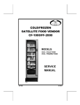
SERVICE MODE BUTTON
To begin the SERVICE MODE, press the
SERVICE MODE BUTTON located on the
upper right corner of the controller
(cover). See Figure 1.
To exit the SERVICE MODE, press the
SERVICE MODE BUTTON.
NOTES
If credit exists when entering the SERVICE
MODE, then it will be restored when the
machine is returned to SALES MODE.
While in SERVICE MODE, the controller will
automatically exit back to SALES MODE if
no key is pressed for approximately 25
seconds.
Figure 1. Controller Cover
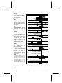
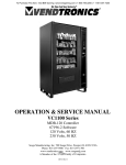
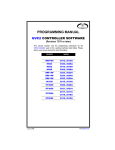
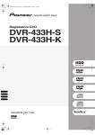
KEYPAD
Press the buttons on the keypad as instructed by the step-by-step instructions in
this manual.
NOTE
If the program is not
requiring you to input a
letter or range value, then
buttons A , B , C and E
are used to move between
the various modes, menus
and
sub-menus;
while
the D button is used to
confirm and save a setting.
See Figure 2.
DISPLAY
Watch
the
display
after
pressing the SERVICE MODE
BUTTON
and/or
KEYPAD
BUTTONS to make sure that the
program
is
responding
correctly.
Figure 2. Keypad Buttons in Service Mode
COMBO • SMVI • SM5700 • RFS • RSQF • SC100 • DZ • P/N 4212619
1
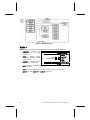
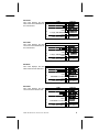
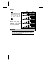
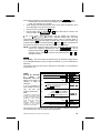
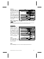
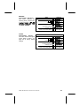
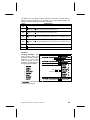
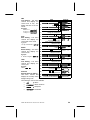
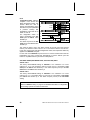
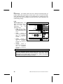
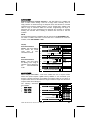
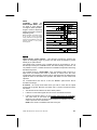
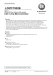
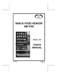
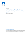
Figure 3 . MENU 1 Diagram
MENU 1
MENU 1 is the first group of service mode menus and it contains the following:
•
•
DIAGNOSE
- Perform selfdiagnostic check and display
possible errors.
1.
DISPLAY
DIAGNOSE
2.
Press A or C
to scroll available menus.
MOTOR
ACCOUNT
COIN
TEST
MENU 2
3.
Press Service Button .
(Sales Mode)
MOTOR
- Displays working
motors and configures currently
working motors.
STEP
Press Service Button .
•
ACCOUNT
•
COIN - For loading or unloading the coin mech tubes and set unconditional acceptance
•
TEST - Test vend a selection motor or range of selection motors, and test relays.
•
MENU 2 - Access to MENU 2 (and MENU 3) main menus.
- Displays various
types of cash and vend totals.
and exact change.
2
COMBO • SMVI • SM5700 • RFS • RSQF • SC100 • DUAL ZONE • P/N 4212619
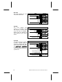
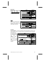
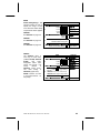
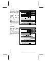
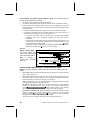
DIAGNOSE
This menu is used to perform a
self-diagnostics check and display
results. The steps are listed at
right.
It is possible that a sequence of
error
codes
could
follow
the VMC display if multiple errors
are found with that device.
1.
STEP
Press Service Button .
DISPLAY
DIAGNOSE
2.
Press B .
See Table 1 on page 3.
VMC
OK
CHANGER OK
VALIDATOR
READER OK
3.
Press Service Button .
(Sales Mode)
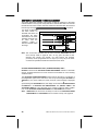
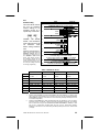
The diagnostics for the VMC will include an error code if any motor in the
configuration has been flagged as bad. In addition, the error code for the bad motor
will indicate why. A definition of possible error codes is shown in Table 1 on
page 3.
For software versions 67149-1, 67149-2, and 67154-1, the diagnostics provides no
indication as to which motor has failed.
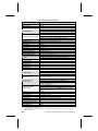
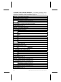
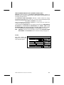
Table 1. Error Codes
ERROR CODE
VMC 1
VMC 2
ERROR DESCRIPTION
Too little motor current (under 100mA). For an example, the display will
show VMC A1 1 (software versions 67149-2 and earlier display
only VMC
1 if any motor in the configuration exhibits this problem).
Too much time to complete vend (9 seconds). For an example, the display
will show VMC C2 2 (software versions 67149-2 and earlier display
only VMC
2 if any motor in the configuration exhibits this problem).
VMC 4
NOVRAM checksum error. The display would read VMC
VMC 5
Health & safety error on temperature sensor 1. The display would
read VMC
5 .
Health & safety error on temperature sensor 2. The display would
read VMC
6 .
VMC 6
4
VMC 7
VMC 8
The door is still open after 30 minutes VMC
VMC 9
Selection was not detected by optical sensor and, as such, is considered
sold out. ). For an example, the display will show VMC A1 9
CHANGER 3
Loss of changer communications or no changer. The display would
show CHANGER
3 .
7 .
Eyes on the activated optical sensor are blocked.
(see Note)
VALIDATOR7
(see Note)
READER 8
(see Note)
Loss of bill validator communications or no bill validator. The display would
read VALIDATOR7 (Applies only to the MDB version of the controller)
Loss of card reader communications or no card reader. The display would
read READER 8 (Applies only to the MDB version of the controller)
NOTE: For software version 67256-3 and 67257-3 if the VMC 8 iVend optics error
is present the controller will beep once per second until the error is cleared.
The service mode time out is also increased to 5 minutes to allow time for
optics error correction.
Also, if no motors are detected or if no credit can be accepted by any of the
attached MDB devices due to the errors listed below, being reported to the
COMBO • SMVI • SM5700 • RFS • RSQF • SC100 • DZ • P/N 4212619
3
control board, the machine is taken out of service and the message
FUERA DE SERVICIO is displayed.
Changer - Acceptor unplugged or Coin Jam.
Validator - Defective Motor, Sensor Bad, ROM checksum or Validator
Jammed.
Cord Reader - Malfunction Errors
•
0x0A and
•
0x80 - 0xBF.
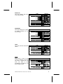
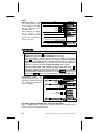
MOTOR
This menu is used to display the number of working motors or to configure the
vendor to currently working motors.
MOTORS
This menu is used to display the
number of working motors.
1.
STEP
Press Service Button .
DISPLAY
2.
Press C .
MOTOR
3.
Press B .
MOTORS
4.
Press B .
MOTORS 005
5.
Press Service Button .
(Sales Mode)
DIAGNOSE
NOTE: Software revisions 67232-7, 67256-3 and 67257-3 only. Any motors not at
home during sales mode will be moved to home after a motor count.
CONFIG
This menu is used to configure
the vendor to currently working
motors.
1.
STEP
Press Service Button .
DISPLAY
DIAGNOSE
2.
Press C , B .
MOTORS
3.
Press A or C .
CONFIG
4.
Press B .
CONFIGURED
5.
Press Service Button .
(Sales Mode)
1.
Press Service Button .
2.
Press C , C .
3.
Press B .
4.
Press A or C to scroll
through submenus.
5.
Press Service Button .
ACCOUNT
This menu is used to gain
access to additional menus that
display, set ranges, or clear
(reset) data for various types of
cash and vend totals.
Note: For large values of
resettable cash and vends use
RANGE CASH and RANGE
VENDS.
4
ACTION
DISPLAY
DIAGNOSE
ACCOUNT
HIST SALES
HIST COUNT
RES SALES
RES COUNT
RDR SALES
2ND VEND
SET RANGE
RANGE CASH
RANGEVENDS
CLEAR
(Sales Mode)
COMBO • SMVI • SM5700 • RFS • RSQF • SC100 • DUAL ZONE • P/N 4212619
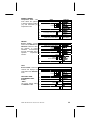
HIST SALES
This menu displays the total
sales value since initialization of
the control board.
1.
STEP
Press Service Button .
DISPLAY
2.
Press C , C .
3.
Press B .
HIST SALES
4.
Press B
to display Total Sales Value.
$00000.00
5.
Press E .
HIST SALES
6.
Press Service Button .
(Sales Mode)
1.
STEP
Press Service Button .
DIAGNOSE
2.
Press C , C , B .
HIST SALES
3.
Press C .
HIST COUNT
4.
Press B
to display Total Vend Count.
00000000
5.
Press E .
HIST COUNT
6.
Press Service Button .
(Sales Mode)
1.
STEP
Press Service Button .
DIAGNOSE
2.
Press C , C , B , C .
3.
Press C .
4.
Press B
Total Sales since last reset.
DIAGNOSE
ACCOUNT
HIST COUNT
This menu displays the total
vend count since initialization of
the control board.
DISPLAY
RES SALES
This menu displays the total
sales value since the last reset.
DISPLAY
HIST COUNT
RES SALES
$OOOOOO.OO
RES SALES
5.
Press E .
6.
Press Service Button .
(Sales Mode)
1.
STEP
Press Service Button .
DIAGNOSE
2.
Press C , C , B .
3.
Press C , C .
RES SALES
4.
Press C .
RES COUNT
5.
Press B .
Total Vends since last reset.
RES COUNT
This menu displays the total
vend count since the last reset.
6.
Press E .
7.
Press Service Button .
COMBO • SMVI • SM5700 • RFS • RSQF • SC100 • DZ • P/N 4212619
DISPLAY
HIST SALES
OOOOOOOO
RES COUNT
(Sales Mode)
5
RDR SALES
This menu displays the total
card reader sales value.
1.
STEP
Press Service Button .
DISPLAY
2.
Press C , C , B .
HIST SALES
3.
Press C , C , C .
RES COUNT
4.
Press C .
RDR SALES
5.
Press B .
$OOOOOO.OO
6.
Press E .
RDR SALES
7.
Press Service Button .
(Sales Mode)
1.
STEP
Press Service Button .
DIAGNOSE
DIAGNOSE
2ND VEND
This menu displays total
number of successful vends
that required a second vend
cycle. This value is resettable.
Product must be detected as
being delivered by the optical
sensor.
2.
DISPLAY
Press C , C , B .
HIST SALES
Press C , C , C .
RES COUNT
3.
Press C , C .
2ND VEND
4.
Press B .
OOOOOOOO
5.
Press E .
2ND VEND
6.
Press Service Button .
1.
Press Service Button .
(Sales Mode)
SET RANGE
This menu allows the operator
to define a specific range of
selections to display total value
or total vends since last reset.
Use RANGE CASH or RANGEVENDS
to display totals. Ranges can
only be defined by row and not
by selections.
6
STEP
2.
DISPLAY
DIAGNOSE
Press C , C , B .
HIST SALES
Press C , C , C .
RES COUNT
Press C , C .
2ND VEND
3.
Press C .
SET RANGE
4.
Press B .
SR/ER A-L
5.
6.
Press starting row letter.
Press ending row letter.
7.
Press D to save.
8.
Press Service Button .
SET RANGE
(Sales Mode)
COMBO • SMVI • SM5700 • RFS • RSQF • SC100 • DUAL ZONE • P/N 4212619
RANGE CASH
This menu displays total value
for the defined range.
1.
2.
STEP
Press Service Button .
DISPLAY
DIAGNOSE
Press C , C , B .
HIST SALES
Press C , C , C .
RES COUNT
Press C , C , C .
SET RANGE
3.
Press C .
RANGE CASH
4.
Press B .
$OOOOOO.OO
5.
Press E .
RANGE CASH
6.
Press Service Button .
(Sales Mode)
1.
STEP
Press Service Button .
DIAGNOSE
RANGEVENDS
This menu displays the number
of vended products for the
defined range.
2.
DISPLAY
Press C , C , B .
HIST SALES
Press C , C , C .
RES COUNT
Press C , C , C .
SET RANGE
RANGEVENDS
3.
Press C , C .
4.
Press B .
OOOOOOOO
5.
Press E .
RANGEVENDS
6.
Press Service Button .
(Sales Mode)
1.
STEP
Press Service Button .
DIAGNOSE
2.
Press C , C , B .
3.
Press A .
4.
Press B
to clear all reset-able values.
5.
Press Service Button .
(Sales Mode)
1.
STEP
Press Service Button .
DIAGNOSE
2.
Press C , C , C .
3.
Press B .
4.
Press A or C to scroll
through submenus.
5.
Press Service Button .
CLEAR
This menu clears all reset-table
values.
DISPLAY
HIST SALES
CLEAR
CLEARED
COIN
Coin mode is used to gain
access to additional menus that
can load or unload the coin
mech coin tubes, or sets
Unconditional Acceptance and
Exact Change values.
COMBO • SMVI • SM5700 • RFS • RSQF • SC100 • DZ • P/N 4212619
DISPLAY
COIN
CPO
TUBE FILL
UNCON ACCP
EXACT CHNG
(Sales Mode)
7
CPO
Coin Pay Out - Pays out coins
from the coin mech coin tubes.
1.
STEP
Press Service Button .
2.
Press C , C , C .
3.
Press B , B .
4.
DISPLAY
DIAGNOSE
COIN
DISPENSE
Press 1 to dispense most
significant coin.
Press 2 for next lower
significant coin.
Press 3 to dispense next
lower significant coin.
Press 4 to dispense least
significant coin.
Note: Press and hold down to rapidly
dispense coins.
5.
Press Service Button .
1.
Press Service Button .
(Sales Mode)
TUBE FILL
Tube Fill Mode - This mode
allows
the
controller
to
accurately track the amount of
available coins for change.
The display will show an
increasing total as coins are
entered through the coin mech.
Manually ejecting coins will not
subtract from the total.
STEP
2.
DISPLAY
Press C , C , C .
Press B , C .
DIAGNOSE
COIN
TUBE FILL
FILL COINS
3.
Press B .
4.
Begin loading coins
through the coin slot.
5.
Press Service Button .
(Sales Mode)
1.
STEP
Press Service Button .
DIAGNOSE
00.000
UNCON ACCP
Unconditional Acceptance Sets
the
unconditional
acceptance value. All coins or
bills equal to or less than this
set value will be accepted even
if the changer cannot return an
equal amount of change.
The Unconditional Acceptance
set value is adjustable but the
maximum value is equal to the
largest
denomination
of
currency or coin accepted by
the changer or validator.
2.
Press C , C , C .
Press B , C .
DISPLAY
COIN
TUBE FILL
Press C .
UNCON ACCP
4.
Press B .
00.000
5.
Press numbers on keypad.
3.
6.
Press D to save.
UNCON ACCP
7.
Press Service Button .
(Sales Mode)
If the operator attempts to save a value that exceeds this amount, a warning
message MAXIMUM VALUE will appear and the displayed setting will revert to this
maximum value.
8
COMBO • SMVI • SM5700 • RFS • RSQF • SC100 • DUAL ZONE • P/N 4212619
EXACT CHNG
Exact Change - Sets the exact
change value which also
triggers
the
display
of
the INSERT EXACT CHANGE m
essage.
STEP
Press Service Button .
1.
DISPLAY
DIAGNOSE
Press C , C , C .
COIN
Press B , C , C .
UNCON ACCP
3.
Press C .
EXACT CHNG
4.
Press B .
000.00
5.
Press numbers on keypad.
6.
Press D to save.
EXACT CHNG
7.
Press Service Button .
(Sales Mode)
1.
Press Service Button .
2.
Press A , A .
2.
TEST
This menu provides access to
menu functions that allow the
operator to test motors or test
relay output control lines.
STEP
DISPLAY
DIAGNOSE
TEST
TEST VEND
3.
Press B .
4.
Press A or C to scroll
through submenus.
TEST RELAY
5.
Press Service Button .
(Sales Mode)
TEST VEND
Test Vend Motors - This menu provides functions that allow the operator to test
vend individual motors or a range of motors. The selection and price will display
with the test vend.
If a test vend attempt
on a particular motor
fails,
then
the
controller will beep 3
times.
A successful test
vend on a motor
clears
all
errors
associated with that
selection.
STEP
Press Service Button .
1.
Press A , A , B .
2.
3.
Press B .
Press selection letter and number or
starting and ending selection row letters.
Example: A 1 for selection A1,
or A G selection rows A through G.
4.
Press D to begin test.
5.
Repeat steps 3 and 4 for other selections.
6.
Press E three (3) times to exit.
7.
Press Service Button .
COMBO • SMVI • SM5700 • RFS • RSQF • SC100 • DZ • P/N 4212619
DISPLAY
DIAGNOSE
TEST VEND
SELECT
--
SELECT
A1
A1$001.00
SELECT -TEST VEND
(Sales Mode)
9
TEST RELAY
Testing of Relays - This menu provides functions that allow the operator to test
the operation of the individual relay lines 1 through 3.
RELAY1 - Refrigeration Compressor.
Dual Zone (software 67232 & 67234)
only: If machine is located in a high
ambient temperature environment, the
condenser fan can be run all the time by
turning off the Energy Saver Mode
switch. This switch is located on the
power panel.
RELAY2 - Evaporator Fan
RELAY3 - Heater
Upon exit from the function, the
state of the corresponding relay
control line will revert to a state that
is dependent on the controller's
normal relay control algorithm.
1.
STEP
Press Service Button .
DISPLAY
2.
Press A , A , B .
3.
Press A or C .
4.
Press B .
RELAY1
5.
Press B .
OFF
*
6.
Press B to test.
ON
*
DIAGNOSE
TEST VEND
TEST RELAY
7.
Press D or E to exit.
RELAY1
8.
Press C .
RELAY2
9.
Press B .
OFF
*
10.
Press B to test.
ON
*
Press D or E to exit.
RELAY2
12
Press C .
RELAY3
13.
Press B .
OFF
*
14.
Press B to test.
ON
*
15.
Press D or E to exit.
16.
Press Service Button .
11.
RELAY3
(Sales Mode)
WARNING:
The operator should be aware that operations of the functions within this menu
have direct control over whatever device(s) is/are connected to those lines. With
some devices (such as compressors), there is the potential for damaging the
device with frequent toggling of this line.
10
COMBO • SMVI • SM5700 • RFS • RSQF • SC100 • DUAL ZONE • P/N 4212619
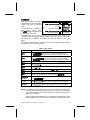
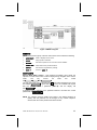
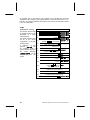
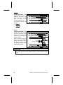
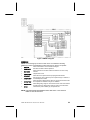
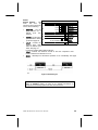
Figure 4. MENU 2 Diagram
MENU 2
MENU 2 is the second group of service mode menus and it contains the following:
•
SERV/CONTR
Hides or displays service menus.
•
PRICE
Assign prices to selections.
•
OPTIONS
Sets various options on the coin mech and the validator.
•
PROMO VEND
Allows free vend of promotional items.
•
CONFIG
Sets vendor to original factory settings.
•
MENU 3
Access to MENU 3.
SERV/CONTR
Service Mode Menu Control - This password accessible menu allows the
operator to control which menus to hide or display during navigation of the service
mode.
The
only
menus
not
under
this
control
are MENU 2 , MENU 3 and SERV/CONTR .
The user enters this menu by pressing the B button after navigating to the menu
item labeled SERV/CONTR . Upon entry to this menu, the controller will request
that the operator enter a password ( D B C A) and the display will
read PASS ---- .
If password entry is exited or if the password entered is incorrect then control
passes back to SERV/CONTR .
NOTE: For software revisions 67256-3 and 67257-3 the default password is
(2462). Also the password can be changed to any numeric sequence
desired, after the correct password has been entered.
COMBO • SMVI • SM5700 • RFS • RSQF • SC100 • DZ • P/N 4212619
11
Refer to Figures 3, 4 & 5 for a diagram of all menus. The following steps set all the
menus
to
factory
default.
The
main
menus DIAGNOSE , MOTOR , ACCOUNT , COIN , TEST and PRICE to display
and hides all other menus.
STEP
1.
Press Service
Button .
DISPLAY
STEP
DIAGNOSE
DISPLAY
28.
Press C
29.
Press B
SHUTDOWN
ON
*
2.
Press A .
MENU 2
30.
Press B
OFF
3.
Press B .
SERV/CONTR
31.
Press D
SHUTDOWN
4.
Press B .
PASS ----
32.
Press C
5.
Press D B C
A.
6
See Note below.
33.
34.
35.
Press B
Press B
Press D
TEMPERTURE
ON
*
OFF
*
TEMPERTURE
36.
Press C
DISCOUNT
7.
Press any key
once or H twice.
DIAGNOSE
37.
Press B
ON
8.
9.
Press C 6 times.
Press B
OPTIONS
ON
38.
39.
Press B
Press D
OFF
*
DISCOUNT
PASS ****
PRG CLAVE?
*
*
*
10.
11.
Press B
Press D
OFF
OPTIONS
*
40.
41.
Press C
Press B
AUTOREINST
ON
*
12.
13.
Press C
Press B
PROMO VEND
ON
*
42.
43.
Press B
Press D
OFF
*
AUTOREINST
14.
15.
Press B
Press D
OFF
*
PROMO VEND
44.
45.
Press C
Press B
COUP/TOKN
ON
*
16.
17.
Press C
Press B
CONFIG
ON
46.
47.
Press B
Press D
OFF
*
COUP/TOKN
18.
19.
Press B
Press D
OFF
CONFIG
48.
49.
Press C
Press B
CAN/BOTTLE
ON
*
20.
21.
Press C
Press B
POS/AUX
ON
50.
51.
Press B
Press D
OFF
*
CAN/BOTTLE
22.
23.
Press B
Press D
OFF
POS/AUX
*
52.
53.
Press C
OPTIC
ON
24.
25.
Press C
Press B
TIME/DATE
ON
*
54.
55.
26.
27.
Press B
Press D
OFF
*
TIME/DATE
56.
*
*
*
See
Press B
Note
Press
B
Below
Press D
Press Service
Button
OFF
OPTIC
*
*
(Sales Mode)
NOTE: For software revisions 67256-3 and 67257-3 the OPTICS menu is OFF by
default. See additional notes on Page 13.
For Software version 67256-3 and 67257-3 the default password is
2 4 6 2.
12
COMBO • SMVI • SM5700 • RFS • RSQF • SC100 • DUAL ZONE • P/N 4212619
If the password entered is correct, then the display will read DIAGNOSE which
corresponds to the first selection that appears upon entry to the service
mode. The operator may now either:
•
Scroll through the remaining functions in the menu which correspond to all of
the configurable menus in the service mode;
•
Enter a function by pressing the B button;
•
Exit this whole menu by pressing the E button which returns control to the
menu just above the SERV/CONTR menu.
If any of the menu items are entered, then the display will change to
ON
* or OFF
* where the * indicates editing mode. This initial
on/off status indicates if the corresponding service menu is currently active or
inactive. Pressing B again will toggle the on/off state. At any time the state may
be stored and this function exited by pressing D . If the E button is pressed then
the status of the specific service mode menu function is not modified.
NOTE: For software revisions 67256-3 and 67257-3 after the correct password is
will be
entered the password programming menu PRG CLAVE ?
displayed. By pressing B this menu is entered and any for digit numeric
sequence can be entered. To save the new password press D or E to
exit without saving.
PRICE
Price Setting - This menu allows the operator three (3) methods to assign prices:
a) To individual selections, b) Over a range of selections, or c) To a combination of
selections.
The maximum price that can be set is 199.99 for a scale factor of 1 and 999.95 for
a scale factor of 5.
ITEM(S)
Pricing by Selection
or
Range
of
Selections - This menu
allows price setting by
selection or range of
selections.
It is not necessary to
enter leading zeros and
only the first five
numbers will be used.
NOTE:
For Protocol A versions of the
controller, the operator should
be aware of changers that are
operating in price holding
mode. When this mode is
active,
product
price
information passed from the
controller to the changer
represents a price address.
1.
STEP
Press Service Mode Button .
2.
Press A , B , C .
3.
Press B .
ITEM(S)
4.
Press B .
SELECT
--
SELECT
A1
5.
6.
Press selection letter and number,
or starting and ending selection letter.
Examples: A 1 for selection A1
or A J for selections A through J.
If correct selection(s) selected,
press D and go to step 9.
If wrong selection(s) selected,
press E and repeat step 7 and 8.
8.
10
PRICE
A1$OOO.5O
Press number keys on keypad
to set the desired price.
7.
9.
DISPLAY
DIAGNOSE
Press D .
SELECT
--
Repeat steps 5 through 8 for other selections.
Press Service Mode Button .
(Sales Mode)
The price set in the controller must be equal to the address multiplied by the lowest
coin accepted by the coin mechanism (the scaling factor).
COMBO • SMVI • SM5700 • RFS • RSQF • SC100 • DZ • P/N 4212619
13
An example price of .05 stored in the controller for a particular item would be
equivalent to the changer's price holding address 1 when the scale factor is 5. In
this case, .05 would be displayed as the item's price and not the actual price stored
in the coin mechanism.
COMBO
Combination Pricing This function allows setup
of several products to be
purchased at a single
combined price.
The combo selection must
not be in the vendor
configuration of currently
working motors.
A maximum of five
products (RG1-RG5) can
be combined under a
combo selection and up to
five combo selections
(COMBO1-COMBO5) can be
programmed
into
the
vendor.
STEP
Press Service Mode Button .
2.
Press A , B , C , B .
3.
Press C .
COMBO
4.
Press B .
SELECT
--
5.
Press selection letter and number.
Example: A 4 for selection A4.
SELECT
A4
6.
Press D .
7.
Press number keys to set the
desired price.
DIAGNOSE
ITEM(S)
A4$OOO.5O
8.
Press D .
9.
Press A or C to select
and link to a combo selection.
10.
Press B .
RG1
11.
Press B .
RG1
*
RG1 XX
*
12.
13.
14.
15.
16.
17.
18.
14
DISPLAY
1.
Press starting selection letter and
number.
Press ending selection letter and
number.
COMBO1
RG1 XX YY*
Press D to save,
or press E to erase and RG2
start again at step 11.
Repeat steps 11 through 14 to combine other
selections to combo selection.
Press E .
SELECT
--
Repeat steps 5 through 16
to create another combo selection.
Press Service Mode Button .
(Sales Mode)
COMBO • SMVI • SM5700 • RFS • RSQF • SC100 • DUAL ZONE • P/N 4212619
OPTIONS
Vending Options - This
menu allows access to the
following optional submenu
features:
Bill Escrow
Force Vend
Maxi Change
Multi Vend
Free Product
1.
STEP
Press Service Mode Button .
DISPLAY
2.
Press A , B , C , C .
3.
Press B .
4.
Press A or C to view
available menus.
5.
Press Service Mode Button .
(Sales Mode)
1.
STEP
Press Service Mode Button .
DIAGNOSE
2.
Press A , B , C , C .
3.
Press B .
4.
Press B to view
or change setting.
5.
Press B to change setting.
6.
Press D to save.
BILL SCROW
7.
Press Service Mode Button .
(Sales Mode)
1.
STEP
Press Service Mode Button .
DIAGNOSE
DIAGNOSE
OPTIONS
BILL SCROW
FORCE VEND
MAX CHANGE
MULTI VEND
FREE PROD
BILL SCROW
Bill Escrow Option - Allows
the last bill accepted to be
returned, provided the bill
acceptor is capable of such
a feature.
DISPLAY
OPTIONS
BILL SCROW
ON
*
OFF
*
FORCE VEND
This option will force the
customer to complete a
purchase once they have
deposited money of any
form.
Note: If a vend is attempted on
a configured selection and the
motor fails during this vend, the
customer will be allowed to
escrow the credit, regardless of
the force vend status.
Press A , B , C .
2.
DISPLAY
PRICE
Press C , B .
BILL SCROW
3.
Press C .
FORCE VEND
4.
Press B to view
or change setting.
5.
Press B to change setting.
ON
*
OFF
*
6.
Press D to save.
FORCE VEND
7.
Press Service Mode Button .
(Sales Mode)
COMBO • SMVI • SM5700 • RFS • RSQF • SC100 • DZ • P/N 4212619
15
MAX CHANGE
Maximum Change Option This option will prevent
change from being returned
to the customer until the
amount of credit has been
reduced to a value less than
or equal to the programmed
maximum change limit.
Note:
The highest value that can
be set for the maximum
price is 199.99 for a scale
factor of 1 and 999.95 for a
scale factor of 5.
1.
STEP
Press Service Mode Button .
DISPLAY
DIAGNOSE
Press A , B , C .
PRICE
Press C , B , C .
FORCE VEND
3.
Press C .
MAX CHANGE
4.
Press B .
5.
To change on/off setting,
press B twice.
6.
Press D to save.
OFF
OFF
ON
ON
7.
Press C .
2.
8.
9.
Press B to view or change the
maximum change limit.
Press numbers on keypad.
10.
Press D to save.
11.
Press Service Mode Button .
1.
Press Service Mode Button .
*
*
VALUE
000.00
VALUE
(Sales Mode)
MULTI VEND
Multi-Vend Option - This
option
will
allow
the
customer to purchase more
than one product if enough
credit has been deposited.
When this option is active,
any credit remaining after a
vend
attempt
is
not
automatically returned. At
this point, the customer has
the option of:
STEP
2.
3.
DISPLAY
DIAGNOSE
Press A , B , C .
PRICE
Press C , B , C .
FORCE VEND
Press C , C .
MULTI VEND
OFF
*
ON
*
4.
Press B .
5.
Press B to change.
6.
Press D to save.
MULTI VEND
7.
Press Service Mode Button .
(Sales Mode)
Making another selection if there's enough credit.
depositing more money (cash credit from a changer or bill acceptor); or
Escrowing the remaining credit. If force vend is also active then the customer
will be forced to attempt the purchase of at least one valid (the selection is in
configuration) item. If a vend is attempted on a configured selection and the
motor fails during this vend, the customer will be allowed to escrow the credit,
regardless of the force vend status.
Note: For card reader sessions, the multi-vend feature will function only if the card
reader supports multiple vend capability.
16
COMBO • SMVI • SM5700 • RFS • RSQF • SC100 • DUAL ZONE • P/N 4212619
FREE PROD
Free Product Option - This
option allows a free product
to be given to the customer
at a preprogrammed vend
interval.
When enabled, every nTH
product will be vended at no
cost, all accumulated credit
will be returned, and the
message "FREE ON US"
will be displayed during the
vend process.
1.
STEP
Press Service Mode Button .
2.
3.
4.
5.
DISPLAY
DIAGNOSE
Press A , B , C .
PRICE
Press C , B , C .
FORCE VEND
Press C , C .
MULTI VEND
Press C .
Press B to view or
change interval setting.
Press number keys on keypad.
6.
Press D to save.
7.
Press Service Mode Button .
FREE PROD
FREE
000
FREE PROD
(Sales Mode)
Setting vend interval to
001
provides a free vend at every
transaction, 000 disables the option, and the maximum valid vend interval
is 255 .
Note: The determination of free product status is made only after credit equal to or greater than the normal
cost of a product has been deposited and the customer has selected the specific product.
PROMO VEND
Promotional Vend - This
function
will
allow
a
promotional product to be
given to a customer for free
in
response
to
their
purchase of another product.
When enabled, purchasing
selection '1' from one of the
two possible promotional
rows will result in both
selection '1' and '2' of that
row to vend sequentially.
OFF/ON
Promo Vend Off/On - This
menu displays and controls
the current status of the
Promo Vend menu.
1.
STEP
Press Service Mode Button .
2.
Press A , B , C .
3.
Press C , C .
4.
Press B .
5.
Press B twice
to change setting.
6.
Press D to save.
7.
Press C .
8.
Press starting letter of
promotional selections row.
Press ending letter of
promotional selections row.
9.
Press D to save.
10.
Press Service Mode Button .
DISPLAY
DIAGNOSE
PRICE
PROMO VEND
OFF
OFF
ON
ON
*
*
RANGE
SR/ER A-A
RANGE
(Sales Mode)
RANGE
Promo Vend Range - This menu is used for setting the promotional rows.
COMBO • SMVI • SM5700 • RFS • RSQF • SC100 • DZ • P/N 4212619
17
CONFIG
Configuration Menu - This
menu provides access to
additional submenus that
allow the operator to restore
some or many of the
controller default settings.
The following submenus are
available:
1.
STEP
Press Service Mode Button .
DISPLAY
2.
Press A , B , A , A .
3.
Press B .
4.
Press A or C
to view available submenus.
5.
Press Service Mode Button .
(Sales Mode)
1.
STEP
Press Service Mode Button .
DIAGNOSE
2.
Press A , B , A .
3.
Press A , B .
4.
Press B .
5.
Press A or C
to select a default setting.
6.
Press D to save.
DEFAULT
SNACK
*
COMBO
*
CHILLED *
CLO FRONT*
FOOD
*
SLACK
*
FROZEN
*
DEFAULT
7.
Press Service Mode Button .
(Sales Mode)
DIAGNOSE
CONFIG
DEFAULT
MESSAGES
OPTIONS
DEFAULT
MESSAGES
OPTIONS
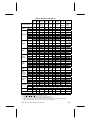
DEFAULT
Configuration Default - This
function allows the operator
to choose a specific set of
default machine settings that
correspond to the type of
vending machine.
Refer to Table 2 on page 19
for the list of factory default
settings that apply to each of
the different machine types
that are applied every time a
machine type is saved.
DISPLAY
MENU 3
CAUTION:
The Point of Sale Message (see page 21) and the Settings for Options (see page
21) are also restored to factory defaults whenever a default machine setting is
saved.
18
COMBO • SMVI • SM5700 • RFS • RSQF • SC100 • DUAL ZONE • P/N 4212619
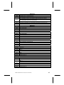
Table 2. Default Configurations 2
SOFTWARE VERSION
AUTO
REINST A-G
TEMPERTURE
SNACK
COMBO
CHILLED
CLO
FRONT
FOOD
SLACK
FROZEN
2 ZONE
2 ZONE
(SZF/DZF)
67185-8
67185-8
67185-8
67217-10/
67257-36
67185-8
67210-5
67209-5
67209-5
67232-76/
67234-34
67232-76
67256-35
67234-34
ON
ON
ON
ON
ON
ON
ON
ON
ON
RANGE
A-L
A-L
A-L
A-L
A-L
A-L
A-L
A-L
A-L
DEGREE
°F
°F
°F
°F
°C / °F
°C
SENSOR1
OFF
ON
°C
ON
°C
ON
ON
ON
°F
ON
ON
ON
SENSOR2
OFF
ON
OFF
OFF
OFF
ON
ON
ON
OFF
SENSOR1
SENSOR1
SENSOR3
SENSOR4
PRIORITY
SET POINT
4°C / 39°F
4°C / 39°F
-10°F
(10°C / 50°F)
(10°C / 50°F)
(16°C / 61°F)
50°F 16°C / 61°F
16°C / 61°F
SENSOR1
61°F
36°F
16°C
2°C
35°F
5°F
SENSOR2
61°F
70°F
16°C
16°C
35°F
50°F
SENSOR1
6°F
10°F
4°C
3°C
8°F
10°F
6°F
4°C / 7°F
4°C / 7°F
SENSOR2
6°F
6°F
4°C
4°C
8°F
1°F
1°F
3°C / 5°F
3°C / 5°F
SENSOR1
15 MIN
15 MIN
15 MIN
15 MIN
15 MIN
30 MIN
30 MIN
10 MIN
10 MIN
SENSOR2
15 MIN
15 MIN
15 MIN
15 MIN
15 MIN
12 HRS
8 HRS
2.5 HRS
2.5 HRS
SENSOR3
SENSOR4
DELTA
SENSOR3
SENSOR4
DEFROST
DURATION
SENSOR3
SENSOR4
DEFROST
PERIOD
SENSOR1
2 HRS
2 HRS
2 HRS
2 HRS
2 HRS
SENSOR2
2 HRS
2 HRS
2 HRS
2 HRS
2 HRS
SENSOR3
SENSOR4
DEFROST
DELAY
HEALTH SAFETY
LEVEL
(FROZEN=0°F)
(SLACK=15°F)
(COLD=41°F)
HEALTH SAFETY
RANGE 1
SENSOR1
0.0 HRS
0.0 HRS
0.0 HRS
SENSOR1
NONE
NONE
NONE
SENSOR2
NONE
NONE
NONE
0.0 HRS
0.0 HRS
0.0 HRS
0.0 HRS
3 MIN
3 MIN
COLD
COLD
SLACK
FROZEN
NONE
NONE
NONE
NONE
H-L
H-L
D-F
D-F
SENSOR3
SENSOR4
SENSOR1
J-L
J-L
J-L
A-L
H-L
SENSOR2
F-L
F-L
F-L
F-L
F-L
OFF
ON
OFF
OFF
OFF
OFF
OFF
OFF
OFF
H-H
J-J
H-H1
H-H1
H-H1
H-H1
H-H1
H-H1
H-H1
ON
OFF
ON
ON
ON
ON
ON
ON
ON
A-G
A-G
A-G
A-G
A-G
A-G
A-G
A-G
A-G
1.00
1.00
1.00 / 50
1.00
2.00
2.00
2.00
50 / 1.00
50
SENSOR3
SENSOR4
CAN-BOTTLE
RANGE
DEPTH
OPTIC
PRICES 3
MOTORS
1.
2.
3.
4.
5.
6.
RANGE
DOUBLE DEPTH
ALL MOTORS CONFIGURED WITH NO ERRORS
SR-ER = Starting Range-Ending Range.
If software should reset on its own, it defaults to this configuration setting.
Software versions 67217-10, 67232-7, 67257-3 & 67256-3 only: the price defaults to 50.
Software version 67234-3 used on SZF/DZF only: SENSOR1 SETPOINT default is 2°C (36°F)
Software version 67256-3 has Advanced Power Management intervals with set points of 10°C and 16°C in addition to the default of 4°C.
Software versions 67256-3, 67257-3 and 67232-7 have a default Auto reinstatement Range of A-G.
COMBO • SMVI • SM5700 • RFS • RSQF • SC100 • DZ • P/N 4212619
19
Table 3. SC100 Dual Satellite (67212-1) Default Configurations2
SOFTWARE VERSION
AUTOREINSTATEMENT
FRZ FRZ
FOD FRZ
FOD FOD
CHL FRZ
CHL FOD
CMO FRZ
CMO FOD
67212-1
67212-1
67212-1
67212-1
67212-1
67212-1
67212-1
ON
ON
ON
ON
ON
ON
ON
A-L
A-L
A-L
A-L
A-L
A-L
A-L
RANGE
DEGREE
TEMPERATURE
SET POINT
DELTA
ON
SENSOR2
ON
DURATION
°F
°F
ON
°F
ON
OFF
°F
ON
OFF
°F
ON
OFF
°F
ON
OFF
ON
ON
ON
SENSOR3
ON
ON
ON
ON
ON
ON
ON
SENSOR4
ON
ON
OFF
ON
OFF
ON
OFF
SENSOR1
-12°F
35°F
35°F
61°F
61°F
36°F
36°F
SENSOR2
50°F
35°F
35°F
61°F
61°F
70°F
70°F
SENSOR3
-12°F
-12°F
35°F
-12°F
35°F
-12°F
35°F
SENSOR4
50°F
50°F
35°F
50°F
35°F
50°F
35°F
SENSOR1
10°F
8°F
8°F
6°F
6°F
10°F
10°F
SENSOR2
1°F
8°F
8°F
6°F
6°F
6°F
6°F
SENSOR3
10°F
10°F
8°F
10°F
8°F
10°F
SENSOR4
1°F
1°F
8°F
1°F
8°F
1°F
SENSOR1
DEFROST
°F
SENSOR1
30 MIN
15 MIN
15 MIN
15 MIN
15 MIN
15 MIN
8°F
8°F
15 MIN
SENSOR2
SENSOR3
30 MIN
30 MIN
15 MIN
30 MIN
15 MIN
30 MIN
15 MIN
SENSOR4
SENSOR1
DEFROST
PERIOD
12 HRS
2 HRS
2 HRS
2 HRS
2 HRS
2 HRS
2 HRS
SENSOR2
SENSOR3
12 HRS
12 HRS
2 HRS
12 HRS
2 HRS
12 HRS
2 HRS
SENSOR4
HEALTH SAFETY
LEVEL
SENSOR1
FROZEN
COLD
COLD
NONE
NONE
NONE
NONE
SENSOR2
(FROZEN=0°F)
(SLACK=15°F)
(COLD=41°F)
SENSOR3
SENSOR1
HEALTH SAFETY
RANGE
FROZEN
FROZEN
COLD
FROZEN
COLD
FROZEN
COLD
SENSOR4
A-C
A-C
A-C
A-C
A-C
A-C
A-C
SENSOR2
SENSOR3
H-L
H-L
H-L
H-L
H-L
H-L
H-L
SENSOR4
ON
CAN-BOTTLE
OPTIC
MOTORS
20
J-J
J-J
DEPTH
DOUBLE
DOUBLE
.50
.50
RANGE
PRICES3
1.
2.
3.
ON
RANGE
.50
.50
.50
.50
.50
MOTORS CONFIGURED WITH NO ERRORS
SR-ER = Starting Range-Ending Range.
If software should reset on its own, it defaults to this configuration setting.
Software versions 67217-10, 67232-7, 67257-3 & 67256-3 only: the price defaults to 50.
COMBO • SMVI • SM5700 • RFS • RSQF • SC100 • DUAL ZONE • P/N 4212619
MESSAGES
Configuration Messages This menu restores the
following factory default Point
of Sale Message: "YOU ARE
GETTING HUNGRY ITS TIME
TO ENJOY A SNACK".
1.
STEP
Press Service Mode Button .
2.
Press A , B , A .
3.
Press A , B .
DISPLAY
DIAGNOSE
MENU 3
DEFAULT
MESSAGES
4.
Press C .
5.
To restore factory default
message, press B
CONFIGURED
6.
Press Service Mode Button .
(Sales Mode)
1.
STEP
Press Service Mode Button .
DIAGNOSE
OPTIONS
Configuration Options This menu restores the option
menus listed in Table 4 (on
page 22) to factory default
settings.
2.
DISPLAY
Press A , B , A .
MENU 3
Press A , B , C .
messages
OPTIONS
3.
Press C .
4.
To restore options default
settings, press B .
CONFIGURED
5.
Press Service Mode Button .
(Sales Mode)
COMBO • SMVI • SM5700 • RFS • RSQF • SC100 • DZ • P/N 4212619
21
Table 4. Default Setting of Options
MENU
Service Menu Configuration
DEFAULT SETTING
All menus restored
Diagnostic errors
Cleared
Accounting Resettable Range
Start row = "A" and End Row = "L"
0
Exact Change Value
Software 67232-7 67234-3: $ 2.00
Software 67217-10, 67232-7, 67256-3 & 67257-3 only: 20.00
0
Unconditional Acceptance Value
Software 67232-7 67234-3: $ 0.25
Software 67217-10, 67232-7, 67256-3 & 67257-3 only: 5.00
All Combo Values
0
All Combo Ranges
Start selection = "A1" and End selection = "A1"
Bill Escrowing
Enabled
Force Vending
Disabled
Multiple Vending
Disabled
Free Product
Disabled
Maximum Change
Disabled
Maximum Change Value
200 x least coin factor
Promotional Vending
Disabled
Promotional Vend Range
Start row = "A" and End Row = "A"
Language
Time Hours Value
English
Software 67217-10, 67232-7, 67256-3 & 67257-3: Spanish
0
Time Minutes Value
0
Time Date Value
1
Time Month Value
1
Time Year Value
0
Daylight Savings
North American Rules
Shutdown
Disabled
Start row = "A" and End Row = "A"
Shutdown Range1
Software 67232-7 only: Range settings for INTERVAL 1 are ignored
Software 67256-3 only: Range settings for INTERVAL 1 and 2 are ignored
Shutdown Start Time1
Intervals 1 thru 4
00:00 ( hours : minutes )
00:00 ( hours : minutes )
Shutdown Stop Time1
Intervals 1 thru 4
Software 67232-7 only: 06:00 (6:00 am) for INTERVAL 1 only
Software 67256-3 only: 06:00 (6:00 am) for INTERVAL 1 only and 23:59
(11:59 pm) for INTERVAL 2 only
All days are turned OFF
Shutdown Days (Note 1)
Intervals 1 thru 4
Software 67232-7 only: All days for INTERVAL 1 only are turned ON
Software 67256-3 only: MON - FRI for INTERVAL 1 and SAT - SUN for
INTERAL 2 only are turned on
Discount
Disabled
Discount Start Time
00:00 ( hours : minutes )
Discount End Time
00:00 ( hours : minutes )
Discount Days
All days are turned off
Discount Range
Start selection = "A1" and End selection = "A1"
Discount Value
0
All Coupon and Token Values
0
All Coupon and Token Ranges
Start selection = "A1" and End selection = "A1"
All Resettable Fields
Cleared
1. Software 67232-7 only: Interval-1 becomes Advanced Power Management instead of Shutdown Mode. Intervals 2 thru
4 are still available for Shutdown Mode.
2. Software 67256-3 only: Interval 1 and 2 become Advanced Power Management instead of Shutdown Mode. Interval 3
and 4 are still available.
22
COMBO • SMVI • SM5700 • RFS • RSQF • SC100 • DUAL ZONE • P/N 4212619
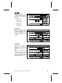
Figure 5. MENU 3 Diagram
MENU 3
MENU 3 is the third group of service mode menus. It includes the following
additional controller customization functions that may be used by an operator:
•
POS/AUX
Allows customization of Point Of Sale messages.
•
TIME/DATE
Sets time and date for timed operations.
•
SHUTDOWN
•
TEMPERTURE
Allows controller to shut down selections based on four time of day
intervals.
Temperature control.
•
DISCOUNT
Allows discount to specific items at preprogrammed intervals.
•
AUTOREINST
•
COUPN/TOKN
•
CAN/BOTTLE
•
OPTIC
Sets a range of rows so that every time a product range is selected, a
vend attempt will be made.
Allows operator to designate the values of coupons and/or tokens that
are accepted from attached changers or validators.
Allows designating ranges of rows that will contain cans and/or bottles.
Provides options for designating ranges of product rows that will be
monitored for product delivery by an optical sensor.
NOTE: FOR SOFTWARE REVISIONS 67256-3 AND 67257-3 THE OPTICS
MENU IS OFF BY DEFAULT.
COMBO • SMVI • SM5700 • RFS • RSQF • SC100 • DZ • P/N 4212619
23
POS/AUX
Message Programming This menu allows access to
additional submenus for
customizing the Point of
Sales
messages.
The
following
menus
are
available:
POS
LANGUAGE
AUX
1.
STEP
Press Service Mode Button .
DISPLAY
2.
Press A , B , A .
3.
Press B .
4.
Press B .
5.
Press A or C
to view available menus.
6.
Press Service Mode Button .
(Sales Mode)
1.
STEP
Press Service Mode Button .
DIAGNOSE
2.
Press A , B , A .
3.
Press B , B .
4.
Press B .
DIAGNOSE
MENU 3
POS/AUX
POS
LANGUAGE
AUX
POS
Point of Sale Message This menu allows the
operator to change the
scrolling Point of Sales
message. It will be
necessary to use the
keypad overlay that came
with your vendor. Refer to
Figure 6 & Figure 7.
Note: If the maximum limit of
105 characters is entered, the
new
message
is
automatically saved and any
subsequent
characters
entered will overwrite the
105th character.
5.
6.
7.
Use keypad overlay and press
new message on keypad.
If finished with message,
press ENTER 2 times
on keypad overlay.
Press Service Mode Button .
DISPLAY
MENU 3
POS
MESSAGE
(new message)
POS
(new message)
Shortcut Suggestion: Use
CONFIG / MESSAGES
the
menu (on page 21) to revert
back to the original factory
default message.
Figure 6. 3x7
Keypad Overlay
24
Figure 7. 5x5
Keypad Overlay
COMBO • SMVI • SM5700 • RFS • RSQF • SC100 • DUAL ZONE • P/N 4212619
The POS menu has special function characters that allow a special effect or
machine specific information to be included in the scrolling POS message. The
following is a list of all the special function characters:
CODE
*B
DESCRIPTION
Beep - When character is reached, a space will appear and controller will beep.
*D1
Display Sensor1 temperature - It will appear in degrees Celsius or Fahrenheit
depending on the unit of temperature the controller is set to.
*D2
Display Sensor2 temperature - It will appear in degrees Celsius or Fahrenheit
depending on the unit of temperature the controller is set to.
*D3
Display Sensor3 temperature – It will appear in degrees Celsius or Fahrenheit
depending on the unit of temperature the controller is set to. Software 67212-1
only.
*D4
Display Sensor4 temperature – It will appear in degrees Celsius or Fahrenheit
depending on the unit of temperature the controller is set to. Software 67212-1
only.
*P
Pause - When character is reached, scrolling will stop for 1/2 second.
*T
Time - Current time will be displayed in military format "hours.minutes".
LANGUAGE
Language Message - This
menu function allows the
operator to choose a specific
language in which sales
mode messages will be
displayed. The following is a
list of languages available:
•
•
•
•
•
•
•
•
ENGLISH
FRENCH
GERMAN
AUXILIARY
ITALIAN
DUTCH
SPANISH
DANISH
1.
STEP
Press Service Mode Button .
Press A , B , A .
2.
Press B , B .
DISPLAY
DIAGNOSE
MENU 3
POS
6.
Press D to save.
LANGUAGE
ENGLISH *
FRENCH
*
GERMAN
*
AUXILIARY*
ITALIAN *
DUTCH
*
SPANISH *
DANISH
*
LANGUAGE
7.
Press Service Mode Button .
(Sales Mode)
3.
Press C .
4.
Press B .
5.
Press A or C
to select a language.
If AUXILIARY is selected, then an alternative list of operator created sales mode
messages will be used.
COMBO • SMVI • SM5700 • RFS • RSQF • SC100 • DZ • P/N 4212619
25
CUSTOMER LEAD THROUGH MESSAGES - The following messages will be
affected by the language selection and will be stored in the controller memory to be
displayed as described in section LANGUAGE on page 25.
MESSAGE 1
English
Italian
Dutch
Spanish
Danish
French
German
Auxiliary
PLEASE INSERT EXACT MONEY
PER FAVORE INTRODURRE I PRECISI SOLDI
AFGEPAST GELD IN WERPEN
POR FAVOR DEPOSITE CANTIDAD EXACTA PLEASE INSERT EXACT MONEY
For Software 67217, 67232, 67256 & 67257 Only:
POR FAVOR DEPOSITE LA CANTIDAD EXACTA
INDKAST AFTALTE PENGE
FAITES L'APPOINT PLEASE INSERT EXACT MONEY
ABGEZAHLTES GELD EINWERFEN
[maximum length: 30]
MESSAGE 2
English
Italian
Dutch
Spanish
Danish
French
German
Auxiliary
PLEASE INSERT MORE MONEY
PER FAVORE INTRODURRE PIU SOLDI
MEER GELD IN WERPEN
POR FAVOR DEPOSITE MAS DINERO PLEASE INSERT MORE MONEY
For Software 67217, 67232, 67256 & 67257 Only: POR FAVOR DEPOSITE MAS DINERO
INDKAST FLERE PENGE
MONTANT INSUFFISANT INTRODUISEZ D'AUTRES PIECES PLEASE INSERT MORE
MONEY
MEHR GELD EINWERFEN
[maximum length: 30]
MESSAGE 3
English
Italian
Dutch
Spanish
Danish
French
German
Auxiliary
MAKE ALTERNATE SELECTION
FARE UNA ALTRE SCELTA
ANDERE KEUZE MAKEN
SELECIONE OTRO PRODUCTO MAKE ALTERNATE SELECTION
For Software 67217, 67232, 67256 & 67257 Only: SELECIONE OTRO PRODUCTO
VAELG ANDEN VARE
FAITES UNE AUTRE SELECTION MAKE ALTERNATE SELECTION
ANDERE WARE WAHLEN
[maximum length: 25]
MESSAGE 4
English
Italian
Dutch
Spanish
Danish
French
German
Auxiliary
PLEASE CALL SERVICE
PER FAVORE CHIAMARE SERVIZIO
SERVICEDIENST BELLEN
POR FAVOR LLAMAR A SERVICIO PLEASE CALL SERVICE
For Software 67217, 67232, 67256 & 67257 Only: POR FAVOR LLAMAR A SERVICIO
TILKALD SERVICEMONTOR
DEMANDEZ LE RESPONSABLE PLEASE CALL SERVICE
BITTE KUNDENDIENST RUFEN
[maximum length: 25]
MESSAGE 5
English
Italian
Dutch
Spanish
Danish
French
German
Auxiliary
26
VENDING OPERATION TO RESUME AT hh.mm
VENDING OPERATION TO RESUME AT hh.mm
VENDING OPERATION TO RESUME AT hh.mm
VENDING OPERATION TO RESUME AT hh.mm
For Software 67217, 67232, 67256 & 67257 Only:
LA MAQUINA SE ENCENDERA A LAS hh.mm
VENDING OPERATION TO RESUME AT hh.mm
VENDING OPERATION TO RESUME AT hh.mm
VENDING OPERATION TO RESUME AT hh.mm
[maximum length: 25]
COMBO • SMVI • SM5700 • RFS • RSQF • SC100 • DUAL ZONE • P/N 4212619
MESSAGE 6:
English
Italian
Dutch
MAKE SNACK SELECTION ONLY
DISPONIBILI SOlO LE SELEZIONI SNACK
ALLEEN SNACK KEUZES
SOLO DISPONIBLE PRODUCTOS EN ESPIRAL MAKE SNACK SELECTION ONLY
Spanish
For Software 67217, 67232, 67256 & 67257 Only:
SOLO DISPONSIBLE PRODUCTOS EN EXPIRALES
Danish
French
German
Auxiliary
KUN VALG AF KONFEKTURE MULIGT
English
Italian
Dutch
Spanish
Danish
French
German
Auxiliary
DOOR OPEN ERROR
English
Italian
Dutch
Spanish
Danish
French
German
Auxiliary
VERIFY REFRIGERATION OPERATION
English
Italian
Dutch
Spanish
Danish
French
German
Auxiliary
THANK YOU
GRAZIE
English
Italian
Dutch
FREE ON US
CHOISISSEZ UNIQUEMENT LES CONFISERIES MAKE SNACK SELECTION ONLY
NUR AUSGABE VON SUSSWAREN MOGLICH
[maximum length: 25]
MESSAGE 7:
DOOR OPEN ERROR
DOOR OPEN ERROR
FOR 67232, 67256 - ERROR PUERTA ABIERTA
DOOR OPEN ERROR
DOOR OPEN ERROR
DOOR OPEN ERROR
[maximum length: 25]
MESSAGE 8
VERIFY REFRIGERATION OPERATION
VERIFY REFRIGERATION OPERATION
FOR 67232, 67256 - VERIFICAR OPERACION DE REFRIGERACION
VERIFY REFRIGERATION OPERATION
VERIFY REFRIGERATION OPERATION
VERIFY REFRIGERATION OPERATION
[maximum length: 30]
MESSAGE 9
DANK U
GRACIAS
TAK
MERCI
VIEL. DANK
[maximum length: 10]
MESSAGE 10
Spanish
Danish
French
German
Auxiliary
FREE
*
FREE **
FREE ***
For Software 67217, 67232, 67256 & 67257 Only: GRATIS
FREE ****
FREE *****
FREE******
[maximum length: 10]
COMBO • SMVI • SM5700 • RFS • RSQF • SC100 • DZ • P/N 4212619
27
AUX
Auxiliary Message - This
function allows the operator
to create custom messages
that can be used in place of
the customer lead through
messages.
Refer
to
customer
lead
through
messages in LANGUAGE
section on page 25.
1.
2.
STEP
Press Service Mode Button .
Press A , B , A .
DISPLAY
DIAGNOSE
MENU 3
Press B , B .
POS
3.
Press A .
AUX
4.
Press B .
MESSAGE 01
5.
Press B .
MESSAGE
6.
7.
8.
9.
Use keypad overlay and press
new message on keypad.
If finished with message,
press ENTER 2 times.
MESSAGE 2
Repeat steps 5 through 7
to modify MESSAGE 1 through MESSAGE 9.
Press D to save.
AUX
10.
Press Service Mode Button .
(Sales Mode)
1.
STEP
Press Service Mode Button .
DIAGNOSE
2.
Press A , B , A .
3.
Press B , C .
4.
Press B .
5.
Press A or C
to view available submenus.
6.
Press Service Mode Button .
TIME/DATE
Set Time and Date - This
menu allows access to
submenus that allow the
operator to set the time and
date for timed operations.
The following submenus are
available:
28
TIME
DATE
MONTH
YEAR
DAYLIGHT
DISPLAY
MENU 3
TIME/DATE
TIME
DATE
MONTH
YEAR
DAYLIGHT
(Sales Mode)
COMBO • SMVI • SM5700 • RFS • RSQF • SC100 • DUAL ZONE • P/N 4212619
TIME
Time Setting - This menu
controls and displays the
current time of day. The
display will show a 24 hour
format.
Examples:
08:05 a.m. = TIME O8.O5
01:15 p.m. = TIME 13.15
11:45 p.m. = TIME 23.45
DATE
Date Setting - This menu
controls and displays the
current date of the month.
1.
STEP
Press Service Mode Button .
Press A , B , A .
2.
Press B , C .
DISPLAY
DIAGNOSE
MENU 3
TIME/DATE
4.
Press B .
TIME
5.
Press B .
TIME 23.17
6.
Press numbers on keypad to
change the current time.
7.
Press D to save.
TIME
8.
9.
Press C .
DATE
Press B to display
or change current date.
Press numbers on keypad to
change the date.
DATE
DATE
18
Examples:
th
18 day of the month = DATE 18
10.
11.
Press D to save.
MONTH
Month Setting - This menu
controls and displays the
current month.
12.
Press C .
MONTH
13.
Press B to view setting.
MONTH
14.
Press numbers on keypad to
change the month.
Example:
th
8 month or August = MONTH 08
15.
Press D to save.
16.
Press C .
YEAR
17.
Press B to view setting.
YEAR
18.
Press numbers on keypad to
change the year.
19.
Press D to save.
20.
Press C .
O2
21.
Press B to view
or change the setting.
DAYLIGHT
Daylight Savings Setting This menu controls and
displays the currently active
daylight savings rule.
22.
Press A or C to select the
matching time zone.
23.
Press D to save.
DAYLIGHT
N AMERICA*
OFF
*
AUSTRALIA*
EUROPE
*
DAYLIGHT
24.
Press Service Mode Button .
(Sales Mode)
YEAR
Year Setting - This menu
controls and displays the
current year.
Example:
2002 = YEAR
07
MONTH
02
YEAR
The following is a list of rules available:
OFF
N AMERICA* = North American
EUROPE
AUSTRALIA* = Australian
* = None
* = European
COMBO • SMVI • SM5700 • RFS • RSQF • SC100 • DZ • P/N 4212619
29
SHUTDOWN / ADVANCED POWER MANAGEMENT
This option allows the controller to shut down a range of selections or the entire
machine based on four (4) time of day intervals. If the time falls within one of these
intervals and the entire machine has been selected for shutdown then the customer
lead through message VENDING OPERATION TO RESUME AT hh.mm is scrolled.
If a range of selections
has been chosen for
shutdown that does not
encompass the entire
machine then the same
message will scroll once
for every time the
customer
makes
a
selection that falls within
the range.
1.
2.
STEP
Press Service Mode Button .
Press A . B . A .
Press B . C .
DISPLAY
DIAGNOSE
MENU 3
TIME/DATE
3.
Press C .
SHUTDOWN
4.
Press B .
5.
Press A or C to scroll menus.
OFF
TIME
DAY
RANGE
6.
Press Service Mode Button .
(Sales Mode)
Note: The correct time and date must be set so that the SHUTDOWN intervals
work correctly. Refer to page 28. Also, for any given day these 4 time
intervals may overlap one another. For each interval, the machine
(controller) can be programmed from no days up to every day of the week
on which the specified shutdown time intervals will be active.
FOR SOFTWARE VERSION 67232-7 (SPANISH SZF/DZF) ONLY:
INTERVAL 1 becomes the ADVANCED POWER MANAGEMENT instead of a shutdown
interval. Shutdown intervals 2 thru 4 will continue to be available for use as vending
shutdown timers.
The ADVANCED POWER MANAGEMENT feature reduces the energy consumption of
the refrigeration system from 12:00 am to 6:00 am by increasing the SET POINT for
SENSOR1 to 10°C (50°F). When it is active, the point of sale message is displayed
as ** GRACIAS ** MODO DEL AHORRO DE ENERGIA ACTIVO ** .
Upon entering the SHUTDOWN menu, the display scrolls the menu TEMPORIZADOR
DE ENERGIA 1 O APAGADOR DE TEMPORIZADOR 2-4. (ENERGY TIMER 1 OR
SHUTDOWN TIMER 2-4). Once the enter key is pressed, toggle the status to ON to
turn on the ADVANCED POWER MANAGEMENT and SHUTDOWN interval timers.
Note: TIME/DATE must also be set accurately in order for the ADVANCED POWER
MANAGEMENT and SHUTDOWN timers to activate correctly. See page 28.
30
COMBO • SMVI • SM5700 • RFS • RSQF • SC100 • DUAL ZONE • P/N 4212619
FOR SOFTWARE VERSION 67256-3 (SPANISH SZF/DZF) ONLY:
INTERVAL 1 and 2 becomes the ADVANCED POWER MANAGEMENT instead of a
shutdown interval. Shutdown intervals 3 thru 4 will continue to be available for use
as vending shutdown timers.
The ADVANCED POWER MANAGEMENT Interval 1 feature reduces the energy
consumption of the refrigeration system from 12:00 am to 6:00 am Monday through
Friday by increasing the SET POINT for SENSOR1 to 10°C (50°F).
Interval 2 increases the set point for SENSOR 1 to 16°C (61°F) from 12:00 am to
11:59 pm on Saturday and Sunday.
Upon entering the SHUTDOWN menu, the display scrolls the menu TEMPORIZADOR
DE ENERGIA 1-2 O APAGADOR DE TEMPORIZADOR 3-4. (ENERGY TIMER 1-2 OR
SHUTDOWN TIMER 3-4). Once the enter key is pressed, toggle the status to ON to
turn on the ADVANCED POWER MANAGEMENT and SHUTDOWN interval timers.
Note: TIME/DATE must also be set accurately in order for the ADVANCED POWER
MANAGEMENT and SHUTDOWN timers to activate correctly. See page 28.
OFF (ON)
This menu controls and
displays the on/off status
of the shutdown option.
STEP
1.
Press Service Mode Button .
2.
DISPLAY
DIAGNOSE
Press A , B , A .
MENU 3
Press B , C , C .
SHUTDOWN
OFF
3.
Press B to display the status.
4.
Press B twice to change.
ON
5.
Press D to save.
ON
6.
Press Service Mode Button .
COMBO • SMVI • SM5700 • RFS • RSQF • SC100 • DZ • P/N 4212619
*
(Sales Mode)
31
FOR SOFTWARE VERSION 67232-7 (SPANISH SZF/DZF) ONLY:
The OFF/ON sub-menu controls the status of the ADVANCED POWER
MANAGEMENT and the SHUTDOWN INTERVALS. The factory default setting is OFF.
It must be turned ON to activate all the features of the ADVANCED POWER
MANAGEMENT and SHUTDOWN INTERVALS 2-4. When it is active, the point of sale
message
is
as ** GRACIAS ** MODO DEL AHORRO DE ENERGIA ACTIVO ** .
displayed
FOR SOFTWARE VERSION 67256-3 (SPANISH SZF/DZF) ONLY:
The OFF/ON sub-menu controls the status of the ADVANCED POWER
MANAGEMENT and the SHUTDOWN INTERVALS. The factory default setting is OFF.
It must be turned ON to activate all the features of the ADVANCED POWER
MANAGEMENT and SHUTDOWN INTERVALS 3-4.
TIME
Shutdown Time Interval
- This menu allows
programming of four (4)
shutdown intervals.
Each shutdown interval
consists of a start time
and stop time (in military
time format).
Please refer to Table 5.
Shutdown Chart on page
33 and examples shown
below
before
setting
shutdown time intervals.
STEP
1.
2.
3.
4.
5.
6.
7.
Examples:
1STRT 07.30
1STOP 09.00
8.
Interval 1 Start 7:30 a.m.
Interval 1 Stop 9:00 a.m.
2STRT 11.00
2STOP 13.45
Interval 2 Start 11:00 a.m.
Interval 2 Stop 01:45 p.m.
32
Press Service Mode Button .
DISPLAY
DIAGNOSE
Press A , B , A .
MENU 3
Press B , C , C .
SHUTDOWN
Press B , C .
TIME
Press B to view start time of
shutdown interval.
Press numbers on keypad to
change start time of interval.
1STRT 00.00
Press D to save start time,
and display stop time of interval.
Press numbers on keypad to
change stop time of interval.
1STOP 00.00
Press D to save stop time,
and view start time of next interval.
Note: If invalid time values were
entered, the setting will not be saved.
9.
Repeat steps 5 through 8
for the remaining intervals or if
invalid time values were pressed
until TIME is displayed.
10.
Press Service Mode Button .
2STRT 00.00
TIME
(Sales Mode)
COMBO • SMVI • SM5700 • RFS • RSQF • SC100 • DUAL ZONE • P/N 4212619
DAY
STEP
DISPLAY
Read Shutdown Chart Instructions and fill out the
Shutdown Chart shown on shown below.
Shutdown Day
This menu allows each of
the four (4) shutdown
interval settings to be
activated (on/off) for a
specific day of the week.
Please read Shutdown
Chart Instructions and fill
out
Shutdown
Chart
before setting shutdown
time.
Shutdown Chart Instructions Use a pencil to write down the
Shutdown Interval start and
stop times (in military time) on
the Shutdown Chart shown
below. Also indicate (circle) if
the shutdown interval will be
on/off (active/inactive) for the
specific day of the week. Use it
to record your settings and refer
to it during programming.
1.
Press Service Mode Button .
2.
3.
DIAGNOSE
Press A , B , A .
MENU 3
Press B , C , C .
SHUTDOWN
Press B , C , C .
DAY
4.
Press B .
5.
To change the interval,
press A or C .
6.
Press B .
7.
To change the day,
press A or C ,
8.
To change (on/off) setting press B ,
press A or C .
1SUN
OFF
9.
Press D to save.
10.
Repeat steps 7 through 9
to set other days of the same interval.
To view another interval, press E and go to step 5.
11.
Repeat steps 5 through 10 until all days are set
according to Shutdown Chart.
Press Service Mode Button .
12.
(Sales Mode)
Table 5. Shutdown Chart
INTERVAL 11
START
STOP
1STRT
1STOP
1SUN
1MON
1TUES
1WED
1THUR
1FRI
1SAT
SUN
MON
TUE
WED
THR
FRI
SAT
:
:
ON
ON
ON
ON
ON
ON
ON
OFF
OFF
OFF
OFF
OFF
OFF
OFF
INTERVAL 2
2STRT
2STOP
2SUN
2MON
2TUES
2WED
2THUR
2FRI
2SAT
:
:
ON
ON
ON
ON
ON
ON
ON
OFF
OFF
OFF
OFF
OFF
OFF
OFF
INTERVAL 3
3STRT
3STOP
3SUN
3MON
3TUES
3WED
3THUR
3FRI
3SAT
:
:
ON
ON
ON
ON
ON
ON
ON
OFF
OFF
OFF
OFF
OFF
OFF
OFF
INTERVAL 4
4STRT
4STOP
4SUN
4MON
4TUES
4WED
4THUR
4FRI
4SAT
:
:
ON
ON
ON
ON
ON
ON
ON
OFF
OFF
OFF
OFF
OFF
OFF
OFF
1.
Software version 67232-7 only: When SHUTDOWN is ON, then INTERVAL 1 is factory set to
ON for every day. The machine does not to shut down but to goes into ADVANCED POWER
MANAGEMENT. INTERVAL 1 start time is set to 1STRT 00:00 (12:00am) while stop time is set
to 1STOP 06:00 (6:00am).
2.
Software version 67256-3 only: When SHUTDOWN is ON, then INTERVAL 1 and 2 are factory
set to ON. Interval 1 for Monday - Friday and Interval 2 to Saturday and Sunday. The machine
does not shut down but goes into ADVANCED POWER MANAGEMENT. INTERVAL 1 start
time is set to 1STRT 00:00 (12:00am) while stop time is set to 1STOP 06:00 (6:00am).
INTERVAL 2 start time is set to 1STRT 00:00 (12:00am) while stop time is set to 1STOP 23:59
(11:59pm).
COMBO • SMVI • SM5700 • RFS • RSQF • SC100 • DZ • P/N 4212619
33
RANGE
Shutdown Range - This
menu option sets the range
of the selection rows that
will be affected by the
shutdown option.
Valid selection row letters
are A through L. The
ending row letter must be
greater than or equal to the
starting row letter.
STEP
Press Service Mode Button .
1.
2.
DISPLAY
DIAGNOSE
Press A , B , A .
MENU 3
Press B , C , C .
SHUTDOWN
Press B , C , C .
DAY
3.
Press C .
RANGE
4.
Press B .
SR/ER A-J
5.
Press starting row letter on keypad.
Press ending row letter on keypad.
6.
Press D to save.
7.
Press Service Mode Button .
RANGE
(Sales Mode)
TEMPERTURE
NOTE:
While in Sales Mode, press 0 to display the current temperature sensor readings.
SENSOR2 will display on the left while SENSOR1 is on the right.
SC100 Dual Satellite software version 67212-1 only: While in Sales Mode,
press 0 to display the current temperature readings of SENSOR1, SENSOR2,
SENSOR3 and SENSOR4. The left or A satellite (for selections A-C) sensors will
display as A Sensor1 SENSOR2 for 3 seconds, then the right or B satellite (for
selections H-L) sensors will display B SENSOR3 SENSOR4 for 3 seconds.
Dual Zone Software 67232, 67234 & 67256 only: While in Sales Mode, press 0 to
display the current temperature readings of each zone and the status of RELAY1
and RELAY3. SENSOR1 is displayed on the left side as Bxxx* where B=bottom,
xxx=temperature°C, *=RELAY1 (compressor) is on. SENSOR2 is displayed on the
right side as Tyyy* where T=top, yyy=temperature°C, *=RELAY3 (heater) is on.
Temperature Control - This
menu has submenus that can
be used to activate and modify
the controller's temperature
control capabilities.
1.
2.
STEP
Press Service Mode Button .
DISPLAY
DIAGNOSE
Press A , B , A .
MENU 3
Press B , C , C .
SHUTDOWN
3.
Press C .
TEMPERTURE
4.
Press B .
5.
Press A or C
to view available menus.
DEGREE F
SENSOR1
SENSOR2
SENSOR3
SENSOR4
PRIORITY
6.
Press Service Mode Button .
(Sales Mode)
FOR DUAL ZONE (SOFTWARE 67232, 67234 & 67256) ONLY:
Refer to PRIORITY setting on page 43 for detailed information on refrigeration and
heating systems for Dual Zone machines.
34
COMBO • SMVI • SM5700 • RFS • RSQF • SC100 • DUAL ZONE • P/N 4212619
DEGREE F - DEGREE C
Temperature Units - This
menu allows the operator
to specify between Celsius
(°C) and Fahrenheit (°F)
temperature units.
SENSOR1
Sensor Control - Except
where noted, SENSOR1 and
SENSOR2 submenus allow
the operator to control
individual
characteristics
that are associated with 2
separate
temperature
sensors.
1.
STEP
Press Service Mode Button .
2.
DISPLAY
DIAGNOSE
Press A , B , A .
MENU 3
Press B , C , C .
SHUTDOWN
Press C .
TEMPERTURE
3.
Press B .
4.
To change units, press B twice.
DEGREE
DEGREE
DEGREE
DEGREE
F
F *
C *
C
5.
Press D to save.
6.
Press Service Mode Button .
(Sales Mode)
1.
STEP
Press Service Mode Button .
DIAGNOSE
2.
DISPLAY
Press A , B , A .
MENU 3
Press B , C , C .
SHUTDOWN
Press C , B .
DEGREE F
SENSOR1
ON
SET POINT
DELTA
DEFROST
H/S
3.
Press C .
4.
Press B .
5.
Press A or C
to view available menus.
6.
Press Service Mode Button .
(Sales Mode)
1.
STEP
Press Service Mode Button .
DIAGNOSE
ON/OFF
Sensor On/Off - This menu
controls and displays the
on/off state of the SENSOR1
menu.
FOR DUAL ZONE
SOFTWARE 67256-3,
67232-7
ONLY:
The factory default setting
for SENSOR2 is OFF.
2.
DISPLAY
Press A , B , A .
MENU 3
Press B , C , C .
SHUTDOWN
Press C , B .
DEGREE F
3.
Press C .
SENSOR1
4.
Press B .
5.
To change setting,
press B twice.
6.
Press D to save.
ON
ON
OFF
OFF
7.
Press Service Mode Button .
COMBO • SMVI • SM5700 • RFS • RSQF • SC100 • DZ • P/N 4212619
*
*
(Sales Mode)
35
SET POINT
Temperature Set Point - This
menu allows the user to set an
ideal operating temperature
that the controller will attempt
to maintain provided the
sensor is already on (enabled).
For
Frozen
or
Slack
health/safety
modes
of
operation,
then
SENSOR1
(compressor)
set
point
temperature
controls
the
refrigeration
system
while
SENSOR2 (evaporator fan) set
point designates the warm
temperature above which the
normal defrost operation will
cease and the refrigeration
operation will restart.
1.
2.
STEP
Press Service Mode Button .
DISPLAY
DIAGNOSE
Press A , B , A .
MENU 3
Press B , C , C .
SHUTDOWN
Press C , B , C .
SENSOR1
Press B .
ON
3.
Press C .
SET POINT
4.
Press B .
5.
Press A to increase or
press C to decrease set point.
6.
Press D to save.
7.
Press Service Mode Button .
36F
SET POINT
(Sales Mode)
In the event that this temperature is not exceeded during the normal defrost
operation, then the expiration of the normal DURATION time will determine the end
of the defrost cycle.
Temperature SENSOR1 and SENSOR2 will also be monitored during the normal
refrigeration cycle to control the enablement of a fan. Specifically, if the
temperature of SENSOR1 is greater than 40 degrees Fahrenheit or the temperature
of SENSOR2 is less than 30 degrees Fahrenheit then the fan will be turned on.
Once the fan turns on, it will remain on until the end of the refrigeration cycle
regardless of the temperature of either sensor.
The maximum value is 70°F or 21°C. The minimum value is -30°F and -34°C. The
temperature rolls over when the user scrolls through the maximum or minimum
values.
FOR DUAL ZONE (SOFTWARE 67232, 67234 & 67256) ONLY:
STEP
SENSOR1 SET POINT
The display is different from
other software versions. The
SET POINT for SENSOR1 is
shown on the left half of the
display while the SET POINT
for SENSOR2 is also shown
on the right half. This is
because the program will
automatically adjust the SET
POINT
of SENSOR2 to
maintain
a
maximum
temperature difference of
23°F (13°C) between the
two zones.
1.
2.
3.
DISPLAY
Press Service Mode Button .
DIAGNOSE
Press A , B , A .
MENU 3
Press B , C , C .
SHUTDOWN
Press C , B , C .
SENSOR1
Press B .
ON
Press C .
SET POINT
4.
Press B .
5.
Press A to increase or
press C to decrease set point.
6.
Press D to save.
7.
Press Service Mode Button .
B
4 T 17*
SET POINT
(Sales Mode)
Refer to Table 2 Default Configurations on page 19 for SENSOR1 factory default
SET POINT settings. Minimum is 35°F (2°C) and maximum is 80°F (27°C).
36
COMBO • SMVI • SM5700 • RFS • RSQF • SC100 • DUAL ZONE • P/N 4212619
NOTES:
If an asterisk (*) appears on the left half, then RELAY1 (compressor) is
currently on. If an asterisk (*) appears on the right half, then RELAY3 (heater)
is currently on. The asterisk may appear or disappear depending on the status
of the relays.
Refer to PRIORITY setting on page 43 for detailed information on refrigeration
and heating systems for Dual Zone machines.
SENSOR2 - SET POINT
The display is different from
other software versions. The
SET POINT for SENSOR2 is
shown on the right half while
the SET POINT for SENSOR1 is
also shown on the left half of
the display. This is because
the program will automatically
adjust the SET POINT of
SENSOR1
to maintain a
maximum
temperature
difference of 23°F (13°C)
between the two zones.
Refer to Table 2 Default
Configurations on page 19
for SENSOR2 factory default
SET POINT settings. Minimum
is 35°F (2°C) and maximum is
80°F (27°C).
STEP
1.
DISPLAY
Press Service Mode Button .
2.
DIAGNOSE
Press A , B , A .
MENU 3
Press B , C , C .
SHUTDOWN
Press C , B , C , C .
SENSOR2
Press B .
ON
3.
Press C .
SET POINT
4.
Press B .
5.
Press A to increase or
press C to decrease set point.
6.
Press D to save.
7.
Press Service Mode Button .
B
4 T 17*
SET POINT
(Sales Mode)
NOTES:
If an asterisk (*) appears on the left half, then RELAY1 (compressor) is
currently on. If an asterisk (*) appears on the right half, then RELAY3 (heater)
is currently on. The asterisk may appear or disappear depending on the status
of the relays.
Refer to PRIORITY setting on page 43 for detailed information on refrigeration
and heating systems for Dual Zone machines.
COMBO • SMVI • SM5700 • RFS • RSQF • SC100 • DZ • P/N 4212619
37
DELTA
Temperature Delta - With the
exception of the Frozen and
Slack refrigeration modes, this
function allows the user to
specify the temperature region
around the set point (described
in previous section) that
refrigeration control will use to
switch on and off.
The refrigeration switch on
point is equivalent to the SET
POINT plus the DELTA value
divided by 2.
The switch off point is the SET
POINT minus the DELTA value
divided by 2.
1.
2.
STEP
Press Service Mode Button .
DISPLAY
DIAGNOSE
Press A , B , A .
MENU 3
Press B , C , C .
SHUTDOWN
Press C , B , C .
SENSOR1
Press B , C .
SET POINT
3.
Press C .
DELTA
4.
Press B .
10F
5.
Press A to increase or
press B to decrease.
6.
Press D to save.
7.
Press Service Mode Button .
DELTA
(Sales Mode)
The value for delta is set in the same manner as the set point (see previous
section). The maximum value is 20°F or 11°C. The minimum value is 5°F and 2°C.
In the case of the Frozen and Slack refrigeration modes, the temperature delta only
applies to the SENSOR1 set point.
For the case of the SENSOR2 set point, there's no need for a delta value since the
temperature only has to exceed this temperature to end the defrost cycle and
there's no equivalent defrost cycle switch on temperature.
FOR DUAL ZONE (SOFTWARE 67232, 67234 & 67256) ONLY:
SENSOR1 - DELTA
The factory default DELTA setting for SENSOR1 is 4°C. Minimum is 3°C and
maximum is 11°C. The compressor switch on point (cut-in) is equivalent to SET
POINT plus the DELTA value divided by 2. The switch off point (cut-out) is the SET
POINT minus the DELTA value divided by 2.
SENSOR2 - DELTA
The factory default DELTA setting for SENSOR2 is 3°C. Minimum is 3°C and
maximum is 11°C. The heater switch on point (cut-in) is equivalent to SET POINT
plus DELTA value divided by 2. The switch off point (cut-out) is the SET POINT
setting.
NOTE:
Refer to PRIORITY setting on page 43 for detailed information on refrigeration
and heating systems for Dual Zone machines.
38
COMBO • SMVI • SM5700 • RFS • RSQF • SC100 • DUAL ZONE • P/N 4212619
DEFROST
Defrost Settings - This
menu
has
four
(4)
submenus which allows the
user to set the following:
•
DURATION - Set the
(time) duration for a
defrost cycle. See
page 40.
•
PERIOD - Set the (time)
period between defrost
cycles. See page 40.
•
DELAY - Controls the
(relative time) delay
when the defrost cycle
starts. See page 41.
1.
STEP
Press Service Mode Button .
2.
DISPLAY
DIAGNOSE
Press A , B , A .
MENU 3
Press B , C , C .
SHUTDOWN
Press C , B , C .
SENSOR1
Press B , C , C .
DELTA
3.
Press C .
DEFROST
4.
Press B .
5.
Press A or C
to view available submenus.
DURATION
PERIOD
DELAY
MANUAL
6.
Press Service Mode Button .
(Sales Mode)
For Dual Zone (software 67232, 67234 & 67256) only:
DELAY - Controls the minimum amount of time the compressor must
remain off before it is allowed to turn on.
•
MANUAL - Manually force the defrost operation to run immediately. See page
41.
Figure 8. Defrost Cycle
FOR DUAL ZONE (SOFTWARE 67232, 67234 & 67256) ONLY:
Refer to PRIORITY setting on page 43 for detailed information on
refrigeration and heating systems for Dual Zone machines.
COMBO • SMVI • SM5700 • RFS • RSQF • SC100 • DZ • P/N 4212619
39
DURATION
This menu sets the length
of time of a defrost cycle.
The maximum value is 60
minutes. The minimum
value is 10 minutes.
Refer to Table 2 on page
19 for factory default
settings.
1.
2.
STEP
Press Service Mode Button .
DISPLAY
DIAGNOSE
Press A , B , A .
MENU 3
Press B , C , C .
SHUTDOWN
Press C , B , C .
SENSOR1
Press B , C , C , C .
DEFROST
3.
Press B .
DURATION
4.
Press B .
10 MIN
5.
Press C to increase or
press A to decrease.
DURATION
6.
Press D to save.
7.
Press Service Mode Button .
(Sales Mode)
1.
STEP
Press Service Mode Button .
DIAGNOSE
PERIOD
This menu sets the total
amount of continuous time
(hours) a refrigeration
compressor must run
before the defrost cycle
will
execute.
Pressing A or C will
cause the time to increase
or decrease by 1/2 hour
increments. The maximum
and minimum value is
24.0
and
.5
hours
respectively.
Refer to Table 2 on page
19 for factory default
settings.
40
2.
DISPLAY
Press A , B , A .
MENU 3
Press B , C , C .
SHUTDOWN
Press C , B , C .
SENSOR1
Press B , C , C .
DELTA
Press C , B .
DURATION
3.
Press C .
PERIOD
4.
Press B .
12.0 HRS
5.
Press C to increase or
press A to decrease.
6.
Press D to save.
7.
Press Service Mode Button .
PERIOD
(Sales Mode)
COMBO • SMVI • SM5700 • RFS • RSQF • SC100 • DUAL ZONE • P/N 4212619
DELAY
This menu controls the amount
of time delay that will elapse
between the present time and
the time at which the defrost
portion of the refrigeration
cycle will start. Refer to Table
2 on page 19 for factory
default settings.
After this delay has expired,
the normal period setting will
control the time between
defrost cycles and this delay
will revert to 0.0 hours.
1.
STEP
Press Service Mode Button .
2.
DISPLAY
DIAGNOSE
Press A , B , A .
MENU 3
Press B , C , C .
SHUTDOWN
Press C , B , C .
SENSOR1
Press B , C , C .
DELTA
Press C , B , C .
PERIOD
3.
Press C .
DELAY
4.
Press B .
0.00 HRS
5.
Press C to increase or
press A to decrease.
6.
Press D .
7.
Press Service Mode Button .
DELAY
(Sales Mode)
Pressing A or C will cause the time to increase or decrease by 1/2-hour
increments. The maximum value is 24.0 hours. The minimum value is .5 hours
respectively.
FOR DUAL ZONE (SOFTWARE 67232, 67234 & 67256) ONLY:
DELAY sets the minimum amount of time the compressor must remain off before it
is allowed to turn on. The factory default is 3 minutes. The minimum value is 3
minutes and the maximum value is 10 minutes. Refer to Table 2 on page 19 for
other factory default settings.
MANUAL
This menu is to manually force
the defrost operation to run
immediately.
Note that upon exit from
service mode, a new period for
continuous
refrigeration
operation that is shorter than
the current time remaining in
the old refrigeration cycle will
reset the old cycle to the new
programmed period.
Also,
defrost
cycles
will
start
counting down as soon as a
refrigeration cycle starts for
either sensor.
STEP
1.
DISPLAY
Press Service Mode Button .
2.
DIAGNOSE
Press A , B , A .
MENU 3
Press B , C , C .
SHUTDOWN
Press C , B , C .
SENSOR1
Press B , C , C .
DELTA
Press C , B , C , C .
DELAY
3.
Press C .
MANUAL
4.
Press B .
OFF
*
5.
Press B to start manual
defrost.
ON
*
6.
Press D .
7.
Press Service Mode Button .
COMBO • SMVI • SM5700 • RFS • RSQF • SC100 • DZ • P/N 4212619
MANUAL
(Sales Mode)
41
H/S
Health Safety - This submenu allows the user to specify the operating region for
passing health safety requirements and the range of rows over which the health
safety requirements will be applied. If the requirements are violated then those
rows will be shut down accordingly. Note that each sensor has independent H/S
(health safety) settings.
LEVEL
Health Safety Level - This
menu allows the user to
select a health safety
requirement
for
the
particular sensor:
•
•
NONE - (Sensor1, Sensor2
& Sensor3) Ignore health
safety requirements for this
sensor.
COLD - (Sensor1 &
Sensor3) Block designated
rows
if
temperature
exceeds 41°F (5°C) for 5
minutes*.
•
SLACK - (Sensor1 &
Sensor3) Block designated
rows
if
temperature
exceeds 15°F (-9°C) for 15
minutes*.
•
FROZEN - (Sensor1 &
Sensor3) Block designated
rows
if
temperature
exceeds 0°F (-18°C) for 15
minutes*.
1.
2.
STEP
Press Service Mode Button .
DISPLAY
DIAGNOSE
Press A , B , A .
MENU 3
Press B , C , C .
SHUTDOWN
Press C , B , C .
SENSOR1
Press B , C , C , C .
H/S
3.
Press B .
LEVEL
4.
Press B .
5.
Press A or C to select a
health/safety level setting.
6.
Press D to save.
NONE
FROZEN
SLACK
COLD
NONE
LEVEL
7.
Press Service Mode Button .
*
*
*
*
*
(Sales Mode)
*NOTE:
The time requirements for FROZEN or SLACK levels do not apply for a period of
75 minutes immediately following machine filling (door open state), servicing
(service mode button pressed or door open detected) or a defrost cycle. The time
requirements for the COLD setting do not apply for a period of 30 minutes
immediately following machine filling or servicing.
42
COMBO • SMVI • SM5700 • RFS • RSQF • SC100 • DUAL ZONE • P/N 4212619
RANGE
Health Safety Range - This
submenu allows the user to
specify the range of rows
over which the health safety
requirements will be applied.
1.
STEP
Press Service Mode Button .
DISPLAY
DIAGNOSE
Press A , B , A .
MENU 3
Press B , C , C .
SHUTDOWN
Press C , B , C .
SENSOR1
Press B , A , B .
LEVEL
3.
Press C .
RANGE
SENSOR3
See SENSOR1 on page 35.
4.
Press B .
SR/ER A-J
5.
Press starting and ending
selection letters on keypad.
SENSOR4
See SENSOR1 on page 35.
6.
Press D to save.
7.
Press Service Mode Button .
1.
Press Service Mode Button .
SENSOR2
See SENSOR1 on page 35.
2.
RANGE
(Sales Mode)
PRIORITY
The PRIORITY menu is
used only on Dual Zone
(software 67232, 67234 &
67256).
This
menu
designates which zone
sensor has priority. The
factory
default
is
SENSOR1 (lower zone).
The other setting is
SENSOR2 (upper zone).
NOTE: If Sensor 2 is OFF
or not present Sensor 1 is
the priority.
STEP
2.
Press A , B , A .
MENU 3
Press B , C , C .
SHUTDOWN
Press C , B , A .
PRIORITY
3.
Press B to view setting.
4.
Example:
SENSOR1=Cool (Lower Zone) Priority
SENSOR2=Warm (Upper Zone) Priority
5.
Press D to save.
6.
Press Service Mode Button .
Press B to toggle setting.
COMBO • SMVI • SM5700 • RFS • RSQF • SC100 • DZ • P/N 4212619
DISPLAY
DIAGNOSE
SENSOR2
SENSOR1
(Sales Mode)
43
•
If the machine is plugged in and the power switch is on and the door is
open, then the top fan is on. RELAY1 (compressor), RELAY2 (evaporator fan),
and RELAY3 (heater and heater fan) are all turned off. A 30 minute door timer
starts and a compressor delay timer starts. The condenser fan is off. (For Dual
Zone Models 3193 & 3195 only: If Energy Saver Mode switch is off, then the
condenser fan remains on.)
If the door is open for more than 30 minutes, then the controller will resume
closed door operation and set an error code (VMC 7). The DIAGNOSE menu
will also display the current state of the door switch after all other messages (if
any) are displayed. DOOR is displayed if the door switch is in the “door open
position” and no message is displayed if the door switch is in the “closed door
position”. The controller evaluates the PRIORITY setting of the machine and
starts that mode of control. Refer to SENSOR1 OR SENSOR2 sections below.
If a defrost cycle is in progress and the door is opened, then the DURATION
timer continues while the door is open.
The PERIOD timer is reset if the compressor was on and the door was opened
for more than 95% of the defrost DURATION timer setting. If the door was
opened briefly (less than 95% of the defrost DURATION timer setting), then the
PERIOD timer continues even though the compressor is off.
•
If the door is closed, then RELAY2 (evaporator fan) is turned on. When the
compressor delay timer (defrost DELAY) expires, then the controller evaluates
the PRIORITY setting of the machine and starts that mode of control. Refer to
SENSOR1 or SENSOR2 sections below.
SENSOR1
The temperature settings of the cool/lower zone must be satisfied first, only then
can it begin to satisfy the temperature requirements of the warm/upper zone.
Specific details are as follows:
If the temperature at SENSOR1 is greater than or equal to its cut-in temperature and
if the compressor has been off for the amount of time equal to the defrost DELAY
setting, then RELAY1 (compressor) is turned on, RELAY3 (heater and heater fan) is
turned off if it was on and the defrost PERIOD timer starts.
•
If the temperature at SENSOR1 is less than or equal to its cut-out temperature,
then RELAY1 (compressor) is turned off and the compressor delay timer
(defrost DELAY) starts.
•
If the temperature at SENSOR1 has not reached cut-out temperature when
defrost PERIOD timer expires, then RELAY1 (compressor) is turned off and the
compressor delay timer (defrost DELAY) and defrost DURATION timer starts.
The heater system for SENSOR2 is allowed to turn on while the compressor is
off if the temperature at SENSOR2 is less than or equal to its cut-in temperature.
When the defrost DURATION timer expires, then the temperature at SENSOR1 is
checked.
If the temperature at SENSOR1 is less than cut-in temperature, then SENSOR2 is
checked.
•
44
If the temperature at SENSOR2 is less than or equal to its cut-in temperature,
then RELAY3 (heater and heater fan) is turned on and remains on until the
temperature at SENSOR2 is equal to or greater than its cut-out temperature
(SET POINT) or if SENSOR1 is greater than or equal to its cut-in temperature.
COMBO • SMVI • SM5700 • RFS • RSQF • SC100 • DUAL ZONE • P/N 4212619
•
If temperature at SENSOR2 is greater than cut-in temperature (SET POINT), then
SENSOR1 temperature is checked.
SENSOR2
The temperature of the warm/upper zone must be satisfied first, and only then can
it begin to satisfy the temperature requirements of the cool/lower zone. Specific
details are as follows:
If the temperature at SENSOR2 is less than or equal to cut-in temperature, then
RELAY1 (compressor) is turned off, RELAY3 (heater and heater fan) are turned on
and the compressor delay timer (defrost DELAY) is starts.
•
If the temperature at SENSOR2 is greater than or equal to its SET POINT
temperature (cut-out), then RELAY3 (heater and heater fan) are turned off and
SENSOR1 is checked.
If temperature at SENSOR2 is greater than its cut-in temperature, then SENSOR1 is
checked.
•
If the temperature at SENSOR1 is greater than or equal to its cut-in temperature
and if the compressor has been off for a time equal to the defrost DELAY timer
setting, then the defrost PERIOD timer starts and RELAY1 (compressor) is
turned on and remains on until the temperature at SENSOR1 is less than or
equal to its cut-out temperature or the temperature at SENSOR2 is less than or
equal to its cut-in temperature.
•
If the temperature at SENSOR1 has not reached its cut-out temperature when
defrost PERIOD timer expires, then RELAY1 (compressor) is turned off and the
compressor delay timer (defrost DELAY) and defrost DURATION timer starts.
The heater system for SENSOR2 is allowed to turn on while the compressor is
off if the temperature at SENSOR2 is less than or equal to its cut-in temperature.
When the defrost DURATION timer expires then temperature at SENSOR1 is
checked.
DISCOUNT
This menu option will access
to the following sub-menus
that allow the vending
machine
(controller)
to
charge a different price for
selections at different times
or on different days:
•
OFF (ON)
•
TIME
•
DAY
•
RANGE
•
VALUE
1.
STEP
Press Service Mode Button .
Press A , B , A .
2.
Press B , C , C , C .
3.
Press C .
4.
Press B .
5.
Press A or C to
view available sub-menus.
6.
Press Service Mode Button .
COMBO • SMVI • SM5700 • RFS • RSQF • SC100 • DZ • P/N 4212619
DISPLAY
DIAGNOSE
MENU 3
TEMPERTURE
DISCOUNT
OFF
TIME
DAY
RANGE
VALUE
(Sales Mode)
45
OFF (ON)
Discounting On/Off - This
menu controls and displays
the (on/off) status of the
discount mode.
TIME
Discounting Time - This
sub-menu sets the time of
day that the discount mode
is in effect.
1.
2.
STEP
Press Service Mode Button .
Press A , B , A .
MENU 3
Press B , C , C .
SHUTDOWN
Press C , C .
DISCOUNT
Press B .
4.
To change the on/off setting
press B twice.
ON
5.
Press D to save.
ON
6.
Press C .
7.
Press B to view start time.
8.
Press numbers on keypad
to change the start time
RANGE
Discounting Range - Sets
the range of selections to be
discounted.
9.
VALUE
Discounting Value - Sets
the
amount
for
the
discounted price.
Setting a value greater than
or equal to the maximum
priced
product
in
the
machine will make all
products within the discount
range free.
NOTE:
The maximum settable value for
discounting is equal to 199.99 for a
scale factor of 1 and 999.95 for a
scale factor of 5. If the operator
attempts to save a value that
exceeds this amount, a warning
message will appear and the
displayed setting will revert to this
maximum value.
46
OFF
3.
DAY
Discounting Day - Sets the
day(s) of the week the
discount mode is in effect.
Valid selection letters are A
through L. The ending
selection letter must be
equal to or greater than the
starting selection letter.
DISPLAY
DIAGNOSE
Press D to save.
10.
Press numbers on keypad
to change stop time.
11.
Press D to save.
12.
Press C .
13.
Press B to view day setting.
14.
15.
16.
17.
Press A or C to
view another day.
To change on/off setting
press B , then press A or C .
*
TIME
1STRT 00.00
1STOP 00.00
TIME
DAY
SUN OFF
SUN ON
Press D to save.
Repeat steps 14 through 16
to set other days of the week.
18.
Press E .
DAY
19.
Press C .
RANGE
20.
Press B to set discount range.
A1-A1
21.
Press starting selection letter
and number on keypad.
Press ending selection letter
and number on keypad.
22.
Press D to save.
RANGE
23.
Press C .
VALUE
24.
Press B .
000.00
25.
Press numbers on keypad
to set the discount price value.
26.
Press D to save.
27.
Press Service Mode Button .
VALUE
(Sales Mode)
COMBO • SMVI • SM5700 • RFS • RSQF • SC100 • DUAL ZONE • P/N 4212619
AUTOREINST
Auto-Reinstatement of Failed Selections - Use this feature for a satellite soft
drink or similar vendor utilizing a sold out or empty switch. Normally, when an
empty selection is detected during an attempted vend, that selection is recorded
inoperative and requires resetting before it can be vended again. Satellite units
utilize a range of selections within the controller. Programming this range of
selections into the auto reinstatement will eliminate the necessity of manually
resetting the controller after re-loading a selection that went into a sold out
condition.
NOTE:
If iVend™ Optical System is installed, then set optical rows to AUTOREINST ON.
For 67232-7, 67256-3 and 67257-3 a motor time out is considered as a sold out
condition, when AUTOREINST is OFF.
ON (OFF)
Auto-Reinstatement
On/Off - This menu displays
and controls the current
on/off
state
of
autoreinstatement mode.
RANGE
Auto-Reinstatement
Range - This menu allows
the setting of the range of
selection row(s) affected by
the
auto-reinstatement
mode.
1.
STEP
Press Service Mode Button .
Press A , B , A .
2.
DISPLAY
DIAGNOSE
MENU 3
Press B , A , A , A .
COUPN/TOKN
3.
Press A .
4.
Press B to view setting.
AUTOREINST
OFF
5.
Press B twice to toggle off/on.
ON
Press D to save.
ON
6.
7.
Press A or C .
8.
Press B to view RANGE setting.
9.
Press starting and ending
selection letters on keypad.
10.
Press D to save.
11.
Press Service Mode Button .
*
RANGE
SR/ER A-J
RANGE
(Sales Mode)
COUPN/TOKN
Value Coupon and Token - This menu enables the use of coupons and/or
tokens—this option requires a [MDB version] validator or coin mechanism (coin
changer). Several sub-menus are available that allows setting of the values of
coupons and/or tokens. It also allows the range of selection row(s) over which such
coupons and/or tokens will apply.
The following
are available:
•
•
•
•
COUP
COUP
TOKN
TOKN
VALUE
RANGE
VALUE
RANGE
STEP
sub-menus
1.
DISPLAY
Press Service Mode Button .
DIAGNOSE
Press A , B , A .
MENU 3
Press B , A , A .
CAN/BOTTLE
3.
Press A .
4.
Press B .
5.
Press A or C
to view available sub-menus.
COUPN/TOKN
COUP VALUE
COUP RANGE
TOKN VALUE
TOKN RANGE
6.
Press Service Mode Button .
2.
COMBO • SMVI • SM5700 • RFS • RSQF • SC100 • DZ • P/N 4212619
(Sales Mode)
47
COUP VALUE
Coupon Value Setting Sets the value of a coupon
to be used with this vendor.
Up to five different coupons
can be used. Coupons
beyond the first 5 will be
considered
free
vend
coupons.
After
one
coupon
is
accepted, further coupons
will not be accepted until a
successful vend has taken
place.
Note: Entering a price of 0
disables the coupon and it is
considered to be a free vend
token.
1.
2.
3.
STEP
Press Service Mode Button .
Press A , B , A .
MENU 3
Press B , A , A , A .
COUPN/TOKN
Press B .
COUP VALUE
CV1 000.00
4.
Press B .
5.
Press A or C
to view other coupon values.
6.
Press B to change value.
7.
Press number keys on keypad
to set the desired value.
8.
Press D to save.
9.
DISPLAY
DIAGNOSE
COUP VALUE
Repeat steps 4 through 8
to view or set other coupon values.
10.
Press Service Mode Button .
(Sales Mode)
1.
STEP
Press Service Mode Button .
DIAGNOSE
COUP RANGE
Coupon Range Setting Sets a range of selections
where
the
coupon
is
redeemable.
This selection allows the
user to select 5 separate
ranges of products that each
corresponding coupon will
cover.
2.
3.
Press A , B , A .
MENU 3
Press B , A , A .
CAN/BOTTLE
Press A , B .
COUP VALUE
Press C .
COUP RANGE
C1R1
4.
Press B .
5.
Press A or C to view
other coupon range settings.
6.
Press B to change settings.
C1R1
7
Press starting selection letter
and number on keypad.
Press ending selection letter
and number on keypad.
C1R1A1 A2*
8.
Press D to save.
COUP RANGE
9.
10.
48
DISPLAY
*
Repeat steps 4 through 8
o view or set other coupon ranges.
Press Service Mode Button .
(Sales Mode)
COMBO • SMVI • SM5700 • RFS • RSQF • SC100 • DUAL ZONE • P/N 4212619
TOKN VALUE
Token Value Setting - Sets
the values of tokens to be
used with this vendor. Up to
5 different tokens can be
used.
Note: The controller will
assign [these] values to the
first 5 tokens that the
attached validator reports.
Tokens beyond the first 5
will be considered free vend
tokens. After one token is
accepted, further tokens will
not be accepted until a
successful vend has taken
place.
1.
STEP
Press Service Mode Button .
DISPLAY
DIAGNOSE
Press A , B , A .
MENU 3
Press B , A , A .
CAN/BOTTLE
Press A , B , C .
COUP RANGE
Press C .
TOKN VALUE
4.
Press B .
TV1 000.00
5.
Press A or C
to view other token settings.
6.
Press B to change value.
7.
Press numbers on keypad
to set token value.
2.
3.
8.
9.
Press D to save.
TOKN VALUE
Repeat steps 4 through 8 for other token settings.
10.
Press Service Mode Button .
1.
Press Service Mode Button .
(Sales Mode)
TOKN RANGE
Token Range Setting Sets
the
ranges
of
selections a token can be
used with.
STEP
DISPLAY
DIAGNOSE
Press A , B , A .
MENU 3
Press B , A , A .
CAN/BOTTLE
Press A , B , C , C .
TOKN VALUE
Press C .
TOKN RANGE
4.
Press B .
T1R1
5.
Press B to edit.
T1R1
6.
Press the letter and number of
the 1st selection on the keypad.
Press the letter and number of
the 2nd selection on the keypad.
7.
Press D to save.
TOKN RANGE
8.
Press Service Mode Button .
(Sales Mode)
2.
3.
COMBO • SMVI • SM5700 • RFS • RSQF • SC100 • DZ • P/N 4212619
*
49
CAN/BOTTLE
Can/Bottle Control Options This submenu provides the
option of designating ranges of
rows that will contain cans
and/or bottles.
Note: Selections that are designated as
either cans or bottles will have the vend
motor run continuously during the vend
cycle until a drop sensor has signaled
the controller or the maximum vend
time of 9 seconds has expired.
1.
2.
STEP
Press Service Mode Button .
DISPLAY
DIAGNOSE
Press A , B , A .
MENU 3
Press B , A , A .
5.
Press D to save.
CAN/BOTTLE
OFF
RANGE
DEPTH
ON
6.
Press Service Mode Button .
(Sales Mode)
1.
STEP
Press Service Mode Button .
DIAGNOSE
3.
Press B .
4.
Press A or C to scroll menus.
OFF (ON)
Can/Bottle On/Off - Displays
and controls the status of the
Can/Bottle Control Option.
When Can/Bottle Mode is
ON, the Drop Sensor is
enabled for vending of
bottles or cans for the range
selected. Set Can/Bottle
Mode to OFF if bottles or
cans will not be vended.
2.
DISPLAY
Press A , B , A .
MENU 3
Press B , A , A .
CAN/BOTTLE
OFF
3.
Press B .
4.
Press B twice to change.
ON
5.
Press D to save.
ON
6.
Press Service Mode Button .
(Sales Mode)
1.
STEP
Press Service Mode Button .
DIAGNOSE
*
RANGE
Can/Bottle Mode Range This submenu sets the range
of selection rows that will
contain cans and/or bottles.
50
2.
Press A , B , A .
Press B , A , A , B .
DISPLAY
MENU 3
ON
3.
Press C .
RANGE
4.
Press B .
SR/ER H-H
5.
Press starting row letter, then
ending row letter on keypad.
6.
Press D to save.
7.
Press Service Mode Button .
RANGE
(Sales Mode)
COMBO • SMVI • SM5700 • RFS • RSQF • SC100 • DUAL ZONE • P/N 4212619
DEPTH
Can/Bottle
Single
Or
Double Depth Status - Sets
the depth of each selection
for single or double operation.
Single is used for dispensing
bottles and double is used for
dispensing cans.
Note: Can/Bottle On/Off must already
be set to ON to access the Depth
setting. Selections set at single depth
will vend for an additional 2.5 seconds
following detection of the product
delivery signal.
1.
STEP
Press Service Mode Button .
Press A , B , A .
2.
Press B , A , A , B .
DISPLAY
DIAGNOSE
MENU 3
ON
3.
Press A .
DEPTH
4.
Press B .
SELECT H1
5.
Press A or C
to scroll to another selection.
6.
Press B .
DOUBLE
*
7.
Press B to change setting.
SINGLE
*
8.
Press D to save.
SELECT H1
Repeat steps 5 through 8
for other can/bottle selections.
9.
10.
Press E to exit.
11.
Press Service Mode Button .
DEPTH
(Sales Mode)
OPTIC
Optical Sensor Control Options - This submenu provides the operator with
options for designating ranges of product rows that will be monitored for product
delivery by an optical sensor.
This optical sensor connects to the controller through pin 8 of header P7. This is
the same pin used by the Can/Bottle sensor. Due to this sharing of resources, it is
not possible to run the controller with both the Can/Bottle and Optical modes being
simultaneously active.
The controller must be in Sales Mode. If the accumulated credit is equal to or
larger than the selection price when a selection is entered, then the motor
corresponding to that selection will be turned on. Selections that are designated as
optical will have an associated vend operation that differs from the normal vend
operation.
For 5 milliseconds at the start of a vend, the iVend™ optical sensor will be
checked for blockage.
If blocked - the normal home-switch-vend cycle will be used and the optical
sensors will be ignored. Both the vend motor and a 9 second vend timeout timer
are started.
•
The selection motor rotates to the home-switch position.
•
If there is a home-switch signal, then the vend is considered successful.
•
If after 9 seconds and there is no home-switch signal, then the vend failed.
The vend motor is shut down and MAKE ALTERNATE SELECTION is
displayed. The customer can press selection buttons to activate this or another
motor or press the coin return button.
NOTE: Force Vend is overridden under this vend cycle.
COMBO • SMVI • SM5700 • RFS • RSQF • SC100 • DZ • P/N 4212619
51
If not blocked - the iVend™ Sensor System is used. The vend motor and a 9
second vend timeout timer are started.
•
The selection motor rotates to the home-switch position.
•
If a product is detected during this time period, then the vend is considered successful.
•
If after reaching the home-switch position and a product is not detected, then the vend
motor will pause for 1 second while the controller continues to monitor the optical sensor
for product delivery.
• If a product is detected during this pause, then the vend is considered successful.
• If a product is not detected, then the controller initiates a second vend cycle and a 9
second timer while continuing to monitor the optical sensor.
o
If a product is detected during this second cycle, the motor will be stopped
immediately. The vend is considered successful. The 2nd Vend Count is
increased by 1.
o
If a product is not detected and the motor reaches the home-switch position or if a
9 second timer runs out, then the vend has failed or the selection is sold out. Such
a state will trigger the display of the MAKE ALTERNATE SELECTION message.
The amount of credit is displayed. The customer can press selection buttons to
activate this or another motor or press the coin return button.
OFF - ON
Optical On/Off State This menu displays and
controls the current on/off
state of the optical option.
Note: If iVend™ is
present, this is normally
set to ON.
1.
2.
STEP
Press Service Mode Button .
Press A , B , A .
Press B , A
DISPLAY
DIAGNOSE
MENU 3
OPTIC
OFF
3.
Press B .
4.
Press B twice to change setting.
ON
5.
Press D to save.
ON
6.
Press Service Mode Button .
*
(Sales Mode)
FOR SOFTWARE VERSIONS 67232-7, 67256-3 AND 67257-3 ONLY.
NOTE: For software revisions 67256-3 and 67257-3 the OPTICS menu is OFF by
default.
•
When OPTIC is OFF, the machine will operate using the optical sensors and the standard
iVend™ algorithm program.
•
When OPTIC is ON, the iVend™ optical sensors will be checked during the idle sales
mode every 200ms. If there are three (3) or more consecutive readings of a blocked or
disconnected sensor, the VMC Error 8 (optics error) will be set.
When the VMC Error 8 is set, the controller will add to the default point of sale message
an illuminated decimal point on the right-most digit.
For 67232-7 only: When the VMC Error 8 is set and a selection is made, vending is
inhibited. The controller will beep three (3) times and scroll the current Spanish
message SELECIONE OTRO PRODUCTO (select another product). If any credit has
been established, pressing the escrow button shall return it in like coin fashion.
For 67256-3 and 67257-3 only: When the VMC Error 8 is set and a selection is made,
vending is inhibited. The controller will beep three (3) times and scroll the current
Spanish message FUERA DE SERVICIO . If any credit has been established,
pressing the escrow button shall return it in like coin fashion.
Once the vend cycle has begun, the current iVend™ algorithm will be used.
52
COMBO • SMVI • SM5700 • RFS • RSQF • SC100 • DUAL ZONE • P/N 4212619
In the Service Mode, the VMC Error 8 will continue to be visible in the Diagnostics menu.
Upon door switch opening or closing, if the iVend™ sensors continue to be disconnected
or blocked the controller will beep (3) times to alert the service person.
RANGE
Range of Optical Mode This menu allows the
operator to specify which
rows of products are
sensed
for
product
delivery by the optical
sensor.
Note: The last row in the range
may then be selected by entering
any letter that is greater than or
equal to the first row in the range
( A through L ).
1.
STEP
Press Service Mode Button .
2.
DISPLAY
DIAGNOSE
Press A , B , A .
MENU 3
Press B , A , B .
ON
3.
Press C .
RANGE
4.
Press B .
SR/ER A-L
5.
6.
Press starting row letter on keypad.
Press ending row letter on keypad.
7.
Press D to save.
8.
Press Service Mode Button .
COMBO • SMVI • SM5700 • RFS • RSQF • SC100 • DZ • P/N 4212619
RANGE
(Sales Mode)
53
DEX/UCS
DEX/UCS or DEX stands for Data EXchange/Uniform Communications Standard.
Within the vending industry, it defines the transfer of information/data between a
Hand Held Computer (HHC) or data collector and the electronic vending machine.
If the vendor operation will be tracked using a DEX/UCS capable hand held
computer, then please note the following:
•
Just below the instructional decal on the control board cover is the plug-in
point for the connecting cable from the hand-held computer. See Figure 1 on
page 1.
•
The vending machine must be in SALES MODE, and then plug in a HHC and the
vendor will enter DEX/UCS MODE. The exchange of information will begin
automatically. All resettable counters are automatically cleared (set to zero).
•
For software versions 67217-8 or later and 67257 only: Will accept DEX
uploads of prices (PC101, PC102) and asset number (IC106) with a 13
character limit.
The following is a list of the DEX/UCS codes and descriptions:
DEX FIELD
ID101
ID102
VA101
VA102
VA103
VA104
CA201
CA202
CA302
CA303
CA304
CA305
CA306
CA307
CA308
CA401
CA402
CA801
CA1001
CA1401
CA1403
MA202
MA504 block 1
MA504 block 2
MA504 block 3
54
DEX FIELD DESCRIPTION
Machine serial number
Machine model number
("SM6 67185-4 " for the Mdb version and "SM6 67201-2 " for the protocol a version)
Value of all paid sales since initialization
Number of all paid vends since initialization
Value of all paid sales since last reset
Number of all paid vends since last reset
Value of cash sales since initialization
Number of cash vends since initialization
Value of cash to coin box since last reset
Value of cash to tubes since last reset
Value of bills in since last reset
Value of cash in since initialization
Value of cash to coin box since initialization
Value of cash to tubes since initialization
Value of bills in since initialization
Value of cash dispensed since last reset
Value of cash manually dispensed since last reset
Value of cash overpay since last reset
Value of cash filled since last reset
Bill value,($1, 2, 5, 10, & 20)
Number of bills to stacker since last reset
Serial number of the vending machine controller.
Number of product deliveries detected during second vend cycle by optical sensing. (See 2ND
VEND on page 6)
"True" or "False" indication of machine health and safety error
Software versions 67217-10, 67256-3 & 67257-3 only: Value of credit cleared since
initialization
COMBO • SMVI • SM5700 • RFS • RSQF • SC100 • DUAL ZONE • P/N 4212619
DEX FIELD
MA505
TA201
TA202
TA203
TA204
TA205
TA206
TA207
TA208
TA301
TA302
PA101
PA102
PA201
PA202
PA203
PA204
PA303
EA201
EA202
EA204
EA201
EA202
EA204
EA201
EA204
EA201
EA204
EA301
EA302
EA303
EA304
EA305
EA306
EA307
EA501
EA502
DEX FIELD DESCRIPTION
Software versions 67217-10, 67256-3 & 67257-3 only: Value of credit cleared since last reset.
Value of vend token sales since initialization(free token no value)
Value of vend token vends since initialization(free token no value)
Value of vend token sales since last reset
Number of vend token vends since reset
Value of value token sales since initialization
Number of value token vends since initialization
Value of value token sales since last reset
Number of value token vends since initialization
Value of value tokens in since last reset
Value of value tokens in since initialization
Product number
Product price
Number of products vended since initialization
Value of paid product sales since initialization
Number of products vended since last reset
Value of paid product since last reset
Number of test vends since last reset
Event identification; one free product vends
Number of events since last reset
User defined field; value
Event identification; promo vends
Number of events since last reset
User defined field; value
Event identification; tube value (.05,.10,.25, 1.00)
User defined field; value
Event id; value of bills & cash box since last reset
User defined field; value
Number of reads since initialization
Date of this read out
Time of this read out
This terminal/interrogator identification
Date of last read out
Time of last read out
Last terminal/interrogator identification
Date of price setting
Time of price setting
COMBO • SMVI • SM5700 • RFS • RSQF • SC100 • DZ • P/N 4212619
55
NOTES
56
COMBO • SMVI • SM5700 • RFS • RSQF • SC100 • DUAL ZONE • P/N 4212619
NOTES
COMBO • SMVI • SM5700 • RFS • RSQF • SC100 • DZ • P/N 4212619
57
The contents of this publication are presented for informational purposes only, and while every effort has been made to ensure their accuracy, they
are not to be construed as warranties or guarantees, express or implied, regarding the products or services described herein or their use or
applicability. We reserve the right to modify or improve the designs or specifications of such products at any time without notice.
VendNet™
165 North 10th Street
Waukee, Iowa 50263
United States of America
USA & Canada
Service
(800) 833-4411
Parts
(888) 259-9965
Email
Web Site
4212619•G.DOC
International
(515) 274-3641
[email protected]
www.vendnetusa.com