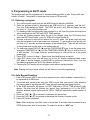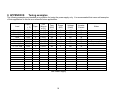
1
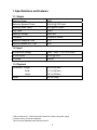
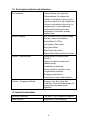
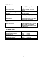
Induction Power Supplies
3kW; 135 – 400kHz
(Integral Heat Station)
User’s Guide
Model 3-135/400-3
Model 3-135/400-3W
Rev E
12/1/04
Table of Contents
1. SPECIFICATIONS AND FEATURES .................................................................................... 3
1.1. Output........................................................................................................................... 3
1.2. Input.............................................................................................................................. 3
1.3. Physical ........................................................................................................................ 3
1.4. Front panel controls and indicators............................................................................... 4
1.5. Internal heat station ...................................................................................................... 4
1.6. Protection...................................................................................................................... 5
1.7. Load.............................................................................................................................. 5
1.8. Cooling Water……………………………………………………………………………….…5
2. GETTING STARTED ............................................................................................................. 6
2.1. Safety Warnings ........................................................................................................... 6
2.2. Set-Up .......................................................................................................................... 6
3. CONNECTIONS..................................................................................................................... 7
3.1. Load.............................................................................................................................. 7
3.2. 230VAC input voltage ................................................................................................... 7
3.3. Circuit Breaker .............................................................................................................. 8
3.4. Terminal Block # 1 ........................................................................................................ 8
3.5. Terminal Block # 2 ........................................................................................................ 8
4. FRONT PANEL OPERATION ............................................................................................... 9
4.1. Limit and trip indicators................................................................................................. 9
4.2. Heat ON/OFF indicators. ............................................................................................ 10
4.3. Program status indicators. .......................................................................................... 10
4.4. Voltage, Current and Frequency Indicators. ............................................................... 10
4.5. Reset Button ............................................................................................................... 10
4.6. Heat switch ................................................................................................................. 10
4.7. Power Pot ................................................................................................................... 10
4.8. MODE switch .............................................................................................................. 11
4.9. E-Stop button.............................................................................................................. 11
4.10. Program buttons ....................................................................................................... 11
4.11. Power Display Indicator ............................................................................................ 11
4.12. Start frequency adjustment ....................................................................................... 11
4.13. Feedback selection................................................................................................... 12
5. PROGRAMMING IN AUTO MODE...................................................................................... 13
5.1. Entering a program ..................................................................................................... 13
5.2. Running a program ..................................................................................................... 14
5.3. Enabling external connections. ................................................................................... 14
6. LOAD STATION TUNING.................................................................................................... 15
6.1. Tuning......................................................................................................................... 15
6.2. Changing the heat station components. ..................................................................... 16
7. APPENDIX A: USER INTERFACE...................................................................................... 17
7.1. Terminal Block 1 ......................................................................................................... 17
7.2. Terminal Block 2 ......................................................................................................... 17
8. APPENDIX B: TUNING EXAMPLES ................................................................................ 18
2
1. Specifications and features
1.1. Output
Maximum Power
3kW1
Maximum Apparent Power
6.6kVA @ 230V input
Minimum Power Factor
0.50 @ 230 V input
Duty Cycle
100%
Maximum Voltage
350V rms 2
Frequency
135kHz to 400kHz
Maximum Response Time
0.1s3
Minimum Allowed OFF-Time
0.5s
1.2. Input
AC line-to-line voltage
208V – 240V ± 10%, 50 to 60Hz
AC line current
14.5A @ 230V
AC power
3.6kVA
1.3. Physical
Dimensions: Length
20.5in (521mm)
Width
11.7in (297mm)
Height
12.7in (323mm)
Weight
43.5lb (20kg)
1
3kW is output power. 3.6kVA input power allows for losses in the power supply.
Limited by rating of resonant capacitors.
3
When using the adjustable start-frequency feature.
2
3
1.4. Front panel controls and indicators
LED Indicators
Yellow indicator for power limit.
Yellow indicator for voltage limit.
Yellow or red indicator (dual color) for
inverter current limit or trip respectively.
Yellow or red indicator (dual color) for
frequency limit or trip respectively.
Individual red indicators for door,
temperature, flow and/or auxiliary
interlock trips.
Numeric Displays
Run time read-outs for output voltage,
inverter current and frequency
Power Meter (0-100%)
Job number (Auto mode)
Step (Auto mode)
Step Time (Auto mode)
Elapsed time (Manual and Auto mode)
Controls – Manual Mode
Rocker switch for output power
ON/OFF.
Single turn knob for power level.
(Manual mode)
Pushbutton to reset trips.
Rocker switch for manual or auto
(programmed) operation.
Emergency stop button.
Freq button to select start frequency
Controls – Programmed Mode
Program, Job, Step, Freq, Pwr,
Time/Freq, Clear and Enter buttons for
programming automatic mode
operation.
1.5. Internal heat station
Resonant capacitors
Two 660nF, 350V capacitors supplied.
Series inductor
Adjustable for load matching.
4
1.6. Protection
Power
Limited to 3kW in any feedback
configuration
Inverter output current
Limited to 70A peak. Short circuit
protected.
Resonant capacitor voltage
Limited to 350V rms
Line current
20A Circuit breaker
Temperature and cooling
Air-cooling provide by three fans.
Heatsink temperature switch for
protection.
Safety Interlocks
Emergency stop button or door switch
opens the main circuit breaker.
1.7. Load
Quality factor of load
Will operate with any load Q (including
resistive loads), provided that the
output frequency and voltage is within
the specifications.
1.8. Cooling Water
Maximum pressure
Minimum differential pressure
Minimum water flow
Maximum inlet water temperature
100PSI
30PSI
.5GPM
(690kPa)
(207kPa)
(0.032l/s)
105°F
(41°C)
Minimum water resistivity
590Ω.in
(1500Ω.cm)
Back of Cabinet
Supply hose location
5
2. Getting started
2.1. Safety Warnings
Have all operation, maintenance and servicing performed by qualified personnel only.
1.
2.
3.
Read this operation manual completely before using the power supply.
Induction heating can be dangerous. Obey all warnings on unit and in manual.
Do not touch live electrical parts. In operation, this means the output connectors,
the work coil, the work piece, and any bus work or cabling connecting them.
WARNING: These symbols, placed at the outputs of the
power supply, warn of the electric shock hazard there
and RF burn hazard at the outputs when the unit is
operating.
Disconnect input power before installing or servicing
this unit. The door interlock will open the breaker if the
cover is removed. However, the input AC voltage is live
at the top of the main circuit breaker.
2.2. Set-Up
The following is a list of steps describing the required actions to get the power supply set up.
1. Loosen the two quarter turn fasteners and remove the cover from the unit. Check for any
visual damage that could have happened during shipment. Check all plug-in connectors of
PCBs.
2. Connect the heating coil to the output of the unit (see section 3.1. on page 7).
3. Read section 4. on page 9 to become familiar with the front panel controls.
WARNING: Make sure that the
power is locked out before
connecting AC power to the unit.
Connect only 208-240VAC.
4. Ensure that the circuit breaker (identified by → in Figure 1) on the unit is in the OFF
position. Connect the power cord to a 230V single phase power source as described in
section 3.2. on page 7.
5. Perform the tuning of the heat station, as described in section 6.1. on page 15.
6. The unit is now ready for operation, and can either be controlled by the front panel (control
selection switches in “INT” position), or by external (control selection switches in “EXT”
position.
6
3. Connections
This section gives a description of the required steps to connect the load, input voltage and
what connections to make to run the unit remotely.
1
2
3
4
5
6
Output for mounting of heating coil
Water input connection
Water output connection
Terminal Block # 1
Terminal Block # 2
Power cord for connection to supply voltage (plug not supplied)
Figure 1: Terminal blocks, circuit breaker, load and input voltage connections.
3.1. Load
Mount the heating coil to the side of the unit (see 1 in Figure 1) using four 10-32 non-magnetic
(e.g. brass) screws. For most applications, a water cooled coil is necessary. If a flow switch is
used in the water path, it can be connected to Pins 4 & 5 of Terminal Block # 2. See Appendix
A for more details.
3.2. 230VAC input voltage
The unit is supplied with a 6 foot long cord (see 2 in Figure 1). Install a single phase grounded
locking plug on the power cord. Connect the plug to an appropriate supply voltage outlet
socket. Note the requirements of the supply voltage given in section 1.2. on page 3. Ensure
that a proper safety ground is connected to the ground terminal of the three-wire socket.
7
3.3. Circuit Breaker
The circuit breaker (see 3 in Figure 1 on page 7) is the is equipped with a shunt trip which will
shut off the power if the cover is removed from the unit, or if the E-Stop switch is pressed.
3.4. Terminal Block # 1
The top three terminals of Terminal Block # 1 can be utilized for remote power reference..
(see 4 in Figure 1 on page 7). The lower three terminals can be used to interface the power
supply with a computer. APPENDIX A: User Interface on page 17 explains the connections in
more detail.
3.5. Terminal Block # 2
Heat On, E-Stop, Auxiliary Interlock, and Reset functions can be run remotely from this
terminal block. There are also relay contacts for Heat On, Power Supply Fault and Power
Supply ready. APPENDIX A: User Interface on page 17 explains the connections in more
detail.
8
4. Front panel operation
This section identifies and describes the various parts of the front panel.
1)
2)
3)
4)
5)
6)
7)
8)
9)
10)
11)
Limit and trip LED
Heat On/Off LEDs
Program Indicators
Volt, Curr and Freq Indicators
Reset button
Heat switch
Power Knob
Mode Switch
E-Stop Switch
Program Buttons
Power Indicator
Figure 2: Front panel layout for model 3-135/400-3.
4.1. Limit and trip indicators.
Identified by 1 in Figure 2 on page 9.
Limit indicators: These indicators are yellow in color and are lit when the heat station is not
properly tuned. The power output of the unit is limited below the desired level set by the power
knob or remote pendant. There are four limit indicators:
• POWER: If lit the power is being limited at 3kW.
• VOLT: If lit the capacitor voltage is being limited at 350V rms.
• FREQ: If lit the circuit is being limited at the resonant frequency of the resonant tank.
• CURRENT: If lit the inverter current is being limited at 70A peak. (Note: The load coil
current could be much higher than 70A peak).
9
If any limit indicators are lit, the heat station components needs to be adjusted to obtain the
required power (see section 6.1. on page 15).
Trip indicators: These indicators are red in color and are lit if the unit is tripped. No power is
being delivered to the load and the heat OFF indicator will be lit. There are six trip indicators:
• FREQ: The circuit momentarily operated below the resonant frequency due to a short in the
load or heat station component or poor tuning of the heat station components.
• CURRENT: The inverter current momentarily exceeded 70A due to a short in the load or
heat station component of poor tuning of the heat station components.
• DOOR: Indicates that the cover of the unit is not replaced.
• TEMP: Indicates that the temperature of the heatsink has exceeded 85°C.
• FLOW: Not used on the 3kW power supply.
• AUX: An auxiliary interlock wired to the unit has tripped it, or the input AC voltage has
dropped.
4.2. Heat ON/OFF indicators.
These LEDs show whether the power supply is generating output or is off. (identified by d in
Figure 2 on page 9).
4.3. Program status indicators.
Identified by 2 in Figure 2 on page 9. These read-outs display the programs status when using
the AUTO mode. The STEP TIME indicator display minutes and the ELAPSED TIME indicator
displays seconds during manual mode operation.
4.4. Voltage, Current and Frequency Indicators.
Identified by 3 in Figure 2 on page 9. These read-outs display the output voltage, the inverter
current and the operating frequency when the power supply is operating.
4.5. Reset Button
Identified by g in Figure 2 on page 9. This button is used to clear the fault indicators if a runtime or interlock trip has occurred. Depressing the button will light the limit and trip indicators
and clear the latch for the fault indicator. If the LED does not go out, then the reason for the
fault is still present.
4.6. Heat switch
Identified by h Figure 2 on page 9. When the power supply is energized, and no fault
indicators are lit, putting this switch in the ON (I) position will start the power supply delivering
heat. When moved back to the OFF (O) position, the heating will be terminated. While in
AUTO mode, the ON position initiates the heat cycle. Putting the HEAT switch in the OFF
position will terminate the heat cycle.
4.7. Power Pot
Identified by iin Figure 2 on page 9. The power pot sets the requested power level as
indicated by the POWER read-out. The level of power feedback is indicated by the percentage
of the LED ring around the POWER POT that is illuminated. This pot is disabled during AUTO
mode operation.
10
4.8. MODE switch
Identified by jin Figure 2 on page 9. In the manual position, MAN, the power supply turns on
with the HEAT switch and power level is controlled by the POWER POT. The programming
the AUTO mode is done with the MODE switch in the MAN position. In the automatic position,
AUTO, the power supply runs programmed jobs. The heat cycle is initiated with the HEAT
switch and the power levels and duration of the cycle are controlled automatically, as
programmed.
4.9. E-Stop button
Identified by k in Figure 2 on page 9. Pressing the E-Stop switch will stop a heat cycle and
operate the shunt trip to open the circuit breaker.
4.10. Program buttons
Identified by l in Figure 2 on page 9. The program buttons are used to program and display
jobs for the power supply to run automatically. See section 5. on page 13 for a description of
how to program the power supply.
4.11. Power Display Indicator
Identified by (11) in Figure 2 on page 9. This read-out displays the demand power when the unit
is in standby or program mode, and displays the power output when the heat cycle is in
progress.
4.12. Start frequency adjustment
The Power Supply starts at a frequency above 400kHz. To generate power it lowers the
frequency until the operating frequency is near, yet still above, the resonance point of the tank
circuit. If this resonant point it fairly low, below 200kHz, then it may take the power supply over
one second to achieve power. A start frequency adjustment is provided to allow the user to
bring the start frequency closer to the operating frequency for quicker response times.
Depress the FREQ button for 3 seconds to enable the adjustment mode, indicated by a
brightening of the Frequency display. At this point, TIME/FREQ (S) and (T) keys can be
used to adjust the start frequency. Press the enter (ENT) button and hold until the frequency
lights dim. The start frequency is now set.
WARNING: Starting the power supply
below the operating frequency of the
tank circuit will result in a frequency trip
and may damage the unit.
11
4.13. Feedback selection
The feedback used by the power supply can be selected by setting a jumper on the control
PCB as shown by Figure 3 on page 12. The default is input power feedback (right most
position). Output voltage, auxiliary input, and inverter output current can also be selected.
Due to the various forms of auxiliary feedback possible, several options are provided. An area
is provided on the PCB for constructing additional circuitry for auxiliary feedback. If a 0-5V DC
feedback signal can be provided, it can be used directly. See Appendix A for more information
on connecting to the power supply.
Figure 3: Feedback jumper location
12
5. Programming in AUTO mode
The power supply can be programmed 12 separate heating profiles or jobs. Each profile can
contain 25 steps. The duration of each step can be up to 640 seconds.
5.1. Entering a program
1. Turn on the power supply and put the MODE selector switch in MANUAL.
2. Enter the program mode by depressing the JOB button for 2 seconds, until the Volt,
Curr, and Freq displays go blank. The STEP will read 1 and JOB will display the last
job used, or 1 if no other job was used.
3. If a heating profile has previously been entered in a Job, then the power and step time
will be displayed on the PWR and STEP TIME readouts.
4. To clear an existing program select the job to be cleared, press the CLR button then
press the ENT button twice. (once for JOB 2nd for Auto Repeat Ar)
5. A power level and a time can be entered for up to 25 steps. The power level will ramp
from the last power level to the power level requested. To get a power level quickly, set
the time to 0.1 seconds and then set power to the desired level. Then set the next step
to that power level and the time to the desired interval.
6. For each step, press PWR UP (S) and the PWR DOWN (T) keys to set the power level
and press TIME/FREQ UP (S) and the TIME/FREQ DOWN (T) keys to enter a time up
to 640 seconds. For longer intervals, several steps in a row can be set to the same
power level.
7. Press STEP to move to step 2. Enter power level and time as in step six.
8. Press ENT (enter) once, this will bring you to the “Ar” display (explained later), press
ENT again to record changes, or press JOB to move onto the next job. Note: If no Job
has been programmed an “AUX” trip indicator will be lit.
9. Pressing the CLR button will exit program mode without saving changes.
Note: Waiting too long to enter values, unit will time out and exit programming.
5.2. Auto Repeat Function
1. Each JOB (except JOB 0) has an auto repeat function, which enables a selected job to
be repeated up to 999 times.
2. To activate auto repeat press and hold JOB for more than one second, after selecting
the job you want to repeat press ENT once, this will open the auto repeat function.
3. In the STEP window Ar will appear, in STEP TIME and in TOTAL TIME window 0’s will
appear. The step time will indicate the “pause” time (indicated by a P in the STEP
window) between repeat cycles and the TOTAL TIME will indicate the repeat number of
cycles.
4. Press the TIME (S) (T) to increase or decrease the pause time.
5. Press the PWR (S) (T) to increase or decrease the number of repeat cycles.
6. Press ENT when completed.
Note: When using any one JOB, a time of more than .3 seconds must be entered at any
STEP and a power level of more than 1% entered to avoid an “AUX” trip.
13
5.3. Running a program
1. With the MODE selector in manual, press JOB to enter program mode. Press the JOB
key to select the job you wish to run. Press enter (ENT).
2. To view the job parameters before running the job, press the STEP button will display
the power and time for each step.
3. Put the MODE selector switch in the AUTO position.
4. Put the HEAT switch in the ON position to run the selected job.
5. To run a program with a momentary “on” signal such as a footswitch:
a)
On Terminal Block 2, connect the control common (#5) with the relay common
(#10).
b)
Connect terminal #1 with terminal #7.
c)
Wire in the momentary closed contact to terminals 1 and 5.
d)
Set E-H (external Heat) to EN (enable) as explained in section 5.4 below.
5.4. Enabling external connections.
The external connections on Terminal Block # 2 can be enabled from the front panel
controls. Pressing the PROG button for 2 seconds will enter the parameter setting mode.
The step button can be used to cycle through the parameters, and the TIME/FREQ UP and
DOWN buttons can be used to change them. For these parameters, EN means Enable
and DIS means Disable.
E-H
External Heat: Disable- The external heat control is not available and only
controlled from the front panel. Enable -The heat cycle is started by connecting
terminal 1 and 5 on Terminal Block # 2.
E-S
External Emergency Stop: Disable -The terminal block connection for E-Stop is
ignored. Enable - terminals 2 & 5 must be connected for the power supply to
operate. When opened, the heat cycle is terminated, but the circuit breaker will
not be opened by the shunt trip as it would by pressing the E-Stop button.
E-A
External Auxiliary Trip: Disable - The terminal block connection for Auxiliary Trip
is ignored. Enable - When terminals 3 & 5 are not connected, an Auxiliary Trip
will display on the front panel, and the unit will not operate.
Note that the RESET function, terminal 4 & 5 is always enabled. There is no soft switch for
this function.
ADR
Address: When the RS485 port is being used to control or monitor the power
supply, a unique ID for the machine can be entered (00-99).
BR
Baud Rate: The communications baud rate for an RS485 connection can be set
here (2.4, 4.8, 9.6, 19.2, 38.4 kbps).
14
6. Load station tuning.
WARNING: Make sure that the
circuit breaker is turned off before
adjusting heat station components.
This section describes the procedures for tuning the heat station so that full power will be
obtained at the desired frequency.
6.1. Tuning.
This section provides the procedures required for the final tuning of the heat station for a
specific heating coil and load. It is assumed that the initial setup of the heat station has been
completed as described in section 3.
The aim of this exercise is to have the unit operating at full power of 3kW without any
indicators lit.
1. Ensure that the heat switch on the front panel is in the OFF position, that the MODE
selection switch is in the MAN (manual) position and that the power level knob is turned
fully counter-clockwise (see Figure 2 on page 9). Turn on the circuit breaker. The green
STANDBY indicator should light up, indicating that the unit is powered up. Press the reset
button if any red trip indicators are lit.
2. Put the HEAT switch in the ON position.
•
If the unit is not delivering full power and the frequency is indicated as ~135kHz (no limit
indicators will be lit), the tank frequency is outside the range of the unit.
•
If the current limit indicator lights up or a current trip occurs, continue increasing the
inductance of the series inductor, i.e. increase the turns of the inductor, until the current
limit indicator stops to light up at full power. Increase the turns using the turn selector
bar, as described in section 6.2.1 on page 16. .
•
If the frequency limit indicator lights up or a frequency trip occurs, continue decreasing
the inductance of the series inductor, i.e. decrease the turns of the inductor, until the
frequency limit indicator stops to light up at full power. Decrease the turns in small
increments by using the shorting bar, as described in 6.2.1 on page 16.
3. Increasing the series inductance until the current reading is around 50% at full power will
optimize the efficiency of the system. This will act to protect the transformer and capacitors
from overheating. Highly recommended!
15
6.2. Changing the heat station components.
This section describes the procedures for changing the heat station components.
6.2.1. Series inductor.
The turn selector bar is identified by c in Figure 4 on page 16. The near position selects zero
turns and the far position eleven turns, as indicated in Figure 4 on page 16. Tighten the bar
into position using the mounting screws.
The shorting bar has to be used for finer adjustment of the series inductance during the tuning
(section 6.1. on page 15) of the heat station.
Example: If the initial setup was for 4 turns (shorting bar not installed), and the turns needs to
be decreased with a quarter turn, install the shorting bar in the low (3) position. If the shorting
bar reaches the high (1) position and the inductance still needs to be decreased, remove the
shorting bar completely and move the turns bar one position forward, e.g. from the 4 turns
position to the 3 turns position.
WARNING: Make sure that the
circuit breaker is turned off before
adjusting heat station components.
1
2
Turn selector bar (0 -11 turns)
Variable shorting bar
Figure 4: Adjusting the Series Inductor
16
7. APPENDIX A: User Interface
7.1. Terminal Block 1
1)
10V reference: This a 10V reference voltage for available for connecting to a
potentiometer remotely. Terminal 1 to top of the pot, terminal 2 to the wiper and terminal
3 (ground) to the bottom of the pot.
2)
Remote Power Reference: When SW301, the INT/EXT switch is set to EXT, the voltage
level at this terminal controls the command reference. O volts is minimum, and 10 volts
is maximum. A PLC can be connected to terminal 2 with its reference to terminal 3.
3)
Reference Ground: Used with terminals 1 & 2, the ground for the power reference.
4)
AFBK Auxiliary Feed Back not currently active.
5)
Common for AFBK.
6)
Flow : by shorting to common can be used to disable internal pressure switch.
7)
Common for Flow.
8-10) This is an RS485 Port. It is configured to be asynchronous, half duplex with an 8 bit, 1
stop bit format. This is a dedicated protocol. The baud rate is selectable to from 2400
baud to 38400 baud.
8)
Terminal A of the RS-485 port.
9)
Terminal B of the RS-485 port.
10)
Common for the RS 485 port.
7.2. Terminal Block 2
See section 5.4. on page 14 for more information on enabling these connections.
1)
START/STOP: Connecting terminal 1 to terminal 5 will start the unit. This is enabled
when E-H is set to EN and the HEAT switch is ON.
2)
E-STOP: Opening a connection between terminal 2 and terminal 5 will stop the heat
cycle. This is enabled when E-S is set to EN. This will not activate the shunt trip. The
front panel E-STOP switch remains in circuit.
3)
AUX: A user defined trip can be wired between terminals 3 and 5. Enabled when E-A
is set to EN.
4)
RESET: Connecting terminal 4 to terminal 5 will issue a fault reset. This is always
enabled.
5)
COMMON
6)
Not used
7-10) 7, 8, & 9 are normally open relay connections with 10 being common for all relays.
7)
HEAT ON: Connected to COM when HEAT cycle is on.
8)
FAULT:
Connected to COM when a FAULT occurs
9)
READY:
Connected to COM when the HEAT cycle is off and no faults exist.
10)
COM:
Common connection for the relays
The contacts for these relays are rated at 250V, 3A.
17
8. APPENDIX B:
Tuning examples
The following examples are intended as a guideline for tuning the power supply only. It is recommended that users add examples
of their applications to this list as a reference future applications.
Load
Caps (
μ F)
Taps
Coil
(# turns
x I.D.)
Freq
(kHz)
Power
(kW)
Voltage
(Vrms)
Inverter
Current
1” steel pipe
1” steel pipe
1” steel pipe
Open
1” steel pipe
1” steel pipe
1”steel pipe
.2” x 1/2” stud
1.320
1.320
1.320
1.320
1.320
0.660
0.210
1.320
8
7
5
8
3
5
10
5
4 x 2.5”
2 x 2.5”
1 x 2.5”
5 x 3/4”
3 x 1.5”
3 x 1.5”
8 x 4”
3 x 3/4”
165
223
349
308
324
392
256
300
3
3
2.9
3
3
1.2
2.3
3
180
160
183
230
90
70
500
230
74
54
70
44
70
24
65
70
3kW Power Supply
18
Notes
Frequency limit
Capacitor limit