1
ANC350 Piezo Motion Controller
EPICS Developers Manual
Issue:
2
Date:
15th April 2009
NAME
Prepared by Alan Greer, Observatory Sciences Ltd.
Checked by
Released by
Philip Taylor, Observatory Sciences Ltd.
DATE
15 April 2009
SIGNATURE
ANC350 Piezo Motion Controller
EPICS Developers Manual
TABLE OF CONTENTS
1
2
3
4
Scope ...................................................................................................................... 3
Reference Documents ............................................................................................ 3
Introduction ............................................................................................................ 4
Requirements ......................................................................................................... 4
4.1
Hardware Requirements................................................................................. 4
4.2
Software Requirements .................................................................................. 4
5 Installation.............................................................................................................. 5
5.1
Installing Under Linux ................................................................................... 5
5.2
Installing Under Windows ............................................................................. 6
6 Running the Test Application ................................................................................ 7
6.1
Running the EPICS Database ........................................................................ 7
6.2
Running the EDM Screens............................................................................. 8
6.3
Global EDM Screen ....................................................................................... 9
6.4
Stepper Module EDM Screen ...................................................................... 10
7 Using the Device Support Code ........................................................................... 11
7.1
Configuration of EPICS Records and Application ...................................... 11
8 Motor Record Support ......................................................................................... 15
8.1
Motor Record Database Configuration ........................................................ 15
8.2
Using the Motor Record with the ANC350 ................................................. 16
Appendix A.
Commands And Status Memory Locations ..................................... 18
15 April 2009
2
ANC350 Piezo Motion Controller
EPICS Developers Manual
1 Scope
This document describes the installation and use of EPICS device support code for the
Attocube Systems’ Piezo Motion Controller (ANC350). The ANC350 electronics is a
closed loop positioning and scanning system which can be used for up to six nano
positioners and scanners. It can be controlled directly from the front panel or through
a USB or ethernet interface. This document describes the EPICS software written to
control the unit via the ethernet interface.
2 Reference Documents
[RD1] IOC Application Developer’s Guide, Marty Kraimer et al.
[RD2] EPICS R3.14 Channel Access Reference Manual, Jeffrey O. Hill.
[RD3] attocube systems’ Piezo Motion Controller User Manual, attocube systems.
[RD4] asynDriver: Asynchronous Driver Support, Marty Kraimer, Eric Norum
and Mark Rivers.
[RD5] Motor Record and related software, Tim Mooney, Joe Sullivan, Ron
Sluiter.
15 April 2009
3
ANC350 Piezo Motion Controller
EPICS Developers Manual
3 Introduction
The ANC350 EPICS software module contains device support code for longin and
longout records to be used with an ANC350 motion controller (and associated
boards). The device support code allows all command and status requests to be issued
through these two records; longin records are used to request data and longout records
are used to send commands (with data if necessary). The module contains two EPICS
database template files, one for global control and one specifically designed to drive a
stepper positioner. Also contained are edm screens that can be used to interact with a
database generated by the template database files. A demonstration application is
provided, set up to work with an ANC350 controller and three stepper boards.
EPICS motor record support is also provided. Although this removes the ability to
fully control all aspects of the controller, it provides a well-recognized interface to
drive the stages as if they were motors.
4 Requirements
This section details the hardware and software requirements for using the ANC350
EPICS device support code.
4.1 Hardware Requirements
The following hardware is required to run the device support code:
- Standard PC with an ethernet port.
- ANC350 present on the network. For operation with the EPICS device
support code the ANC350 should be configured to have a static IP address.
4.2 Software Requirements
The following software is required to run the driver and device support code:
- Linux or Microsoft windows operating system. The device support code has
been written using general asyn and EPICS base function calls and methods
and as a result will be fully functional on any system that can compile the
required versions of EPICS base and the asynDriver module. The device
support code was written on CentOS 4.3 and tested on CentOS 4.3 and
Windows XP.
- EPICS (version 3.14.8 or later)
- EPICS module ‘AsynDriver’ (version 4.10 or later)
- MSI extension for EPICS (version 5 or later). Required if building the
supplied test application
- EDM to run engineering screens, if they are required.
- EPICS module ‘motor’ (version 6.4.2 or later) required to drive the axes using
the standard motor record.
- (Windows only) cygwin installed.
15 April 2009
4
ANC350 Piezo Motion Controller
EPICS Developers Manual
5 Installation
5.1 Installing Under Linux
This section will cover installation of the device support code for the ANC350 on a
Linux operating system. Before performing the following installation, ensure that
EPICS version 3.14.8 or later is installed and the asynDriver version 4.10 or later and
the module motor version 6.4.2 or later have been installed.
Unpack the ANC350 tar file and cd into the top directory. In here you will see the
following files and directories:
Directory
anc350App
Description
This directory contains the device support code, a template
database for a stepper module and a template edm screen
to use with the database template.
ancTest350App
This directory contains a test application. A substitutions
file sets up a system configured for an ANC350 with three
stepper modules.
anc350MotorApp This directory contains the motor record interface code.
configure
The configuration directory.
iocBoot
The boot directory for the test application. It contains the
startup script that defines the IP address of the ANC350
(see below).
Makefile
runTestApp
Linux only. Bash script to start the EPICS test application
and run the edm screens.
runTestAppWin
Windows only. Script to start the EPICS test application.
runGUI
Linux only. Bash script to start the edm application and
open the test edl screen.
Before making the application it is necessary to add references to the EPICS
installation and the asyn installation. Cd into the configure directory and edit the
RELEASE file. Update the lines that define the location of the asyn installation and
the motor module to point to wherever these modules are installed on your system.
For example
ASYN=/usr/software/epics/asyn-4.10
MOTOR=/usr/software/epics/motor-6.4.2
Also update the line that defines the location of your EPICS installation. For example
EPICS_BASE=/usr/software/epics/base-3.14.8.2
Save any changes and exit. Cd back up to the top level. Finally the host architecture
must be defined before the build can commence. From a terminal enter the following
line:
15 April 2009
5
ANC350 Piezo Motion Controller
EPICS Developers Manual
export EPICS_HOST_ARCH=linux-x86
There is a test application supplied with the device support code. If this is to be used
then the startup script should be altered. Cd into the iocBoot/iocancTest350 directory.
Edit the st.cmd file and update the line that configures the asyn IP port with the IP
address of the ANC350 unit on your network.
drvAsynIPPortConfigure(“IP1”,“10.2.2.71:2101”,0,0,0)
Now cd back to the top level and type make to build the device support code and the
test application. The build should complete with no errors.
5.2 Installing Under Windows
This section will cover installation of the device support code for the ANC350 on a
Windows operating system. Before performing the following installation, ensure that
EPICS 3.14.8 or later is installed and the asynDriver version 4.10 or later has been
installed. For the ANC350 test these were both installed using the cygwin (Linuxlike) environment and the gcc compiler (version 3.4.4 for cygwin). All instructions in
this section assume the developer is also using the cygwin environment and associated
tools (www.cygwin.com).
Open a cygwin terminal and unpack the ANC350 tar file. Cd into the top directory.
In here you will see the following files and directories:
Directory
anc350App
Description
This directory contains the device support code, a template
database for a stepper module and a template edm screen
to use with the database template.
ancTest350App
This directory contains a test application. A substitutions
file sets up a system configured for an ANC350 with three
stepper modules.
anc350MotorApp This directory contains the motor record interface code.
configure
The configuration directory.
iocBoot
The boot directory for the test application. It contains the
startup script that defines the IP address of the ANC350
(see below).
Makefile
runTestApp
Linux only. Bash script to start the EPICS test application
and run the edm screens.
runTestAppWin
Windows only. Script to start the EPICS test application.
runGUI
Linux only. Bash script to start the edm application and
open the test edl screen.
Before making the application it is necessary to add references to the EPICS and
installation and the asyn installation. Cd into the configure directory and edit the
RELEASE file. Update the lines that define the location of the asyn installation and
the motor module to point to wherever these modules are installed on your system.
15 April 2009
6
ANC350 Piezo Motion Controller
EPICS Developers Manual
ASYN=/usr/software/epics/asyn-4.10
MOTOR=/usr/software/epics/motor-6.4.2
Also update the line that defines the location of the EPICS installation.
EPICS_BASE=/usr/software/epics/base-3.14.8.2
Save any changes and exit. Cd back up to the top level. Finally the host architecture
must be defined before the build can commence. From a terminal enter the following
line:
export EPICS_HOST_ARCH=cygwin-x86
There is a test application supplied with the device support code. If this is to be used
then the startup script should be altered. Cd into the iocBoot/iocancTest350 directory.
Edit the st.cmd file and update the line that configures the asyn IP port with the IP
address and port number of the ANC350 unit on your network (see Section 7.1). The
example below shows an ANC350 on a network with the IP address 10.2.2.71
listening on port 2101. The details of the ANC350 IP and port configuration can be
found in [RD3].
drvAsynIPPortConfigure(“IP1”,“10.2.2.71:2101”,0,0,0)
Now cd back to the top level and type make to build the device support code and the
test application. The build should complete with no errors.
6 Running the Test Application
Once the system has successfully compiled on either a Windows or Linux OS the test
application should be executed to ensure a connection to the ANC350 is completed.
6.1 Running the EPICS Database
There are two scripts contained in the top-level directory to start the application. For
Linux, execute the script runTestApp. For windows execute the script
runTestAppWin from within the cygwin Bash shell (see section 5.2). Below is an
example of the output generated when the system is started on Linux.
[ajg@osllx8 anc350]$ ./runTestApp
#!../../bin/linux-x86/ancTest350
## You may have to change ancTest350 to something else
## everywhere it appears in this file
< envPaths
epicsEnvSet(ARCH,"linux-x86")
epicsEnvSet(IOC,"iocancTest350")
epicsEnvSet(TOP,"/home/ajg/applications/anc350")
15 April 2009
7
ANC350 Piezo Motion Controller
EPICS Developers Manual
epicsEnvSet(ASYN,"/usr/software/epics/asyn-4.10")
epicsEnvSet(ANC,"/home/ajg/applications/anc350")
epicsEnvSet(EPICS_BASE,"/usr/software/epics/base-3.14.8.2")
cd /home/ajg/applications/anc350
## Register all support components
dbLoadDatabase("dbd/ancTest350.dbd",0,0)
ancTest350_registerRecordDeviceDriver(pdbbase)
## Load record instances
#dbLoadRecords("$(ASYN)/db/asynRecord.db","P=OSL:,R=ASYN,PORT=
IP1,ADDR=0,OMAX=0,IMAX=0")
dbLoadRecords("db/ancTest.db", "")
drvAsynIPPortConfigure("IP1","10.2.2.71:2101",0,0,0)
cd /home/ajg/applications/anc350/iocBoot/iocancTest350
iocInit()
Starting iocInit
##############################################################
##############
### EPICS IOC CORE built on Sep 6 2006
### EPICS R3.14.8.2 $R3-14-8-2$ $2006/01/06 15:55:13$
##############################################################
##############
iocInit: All initialization complete
## Start any sequence programs
#seq sncxxx,"user=ajgHost"
epics>
Once the startup is complete and the records loaded the ANC350 can be controlled by
setting various records present in the database.
6.2 Running the EDM Screens
To allow fast testing some edl engineering screens have been added; these can be
started on Linux by executing the script runGUI present in the top-level directory.
The screens can be converted to other formats (http://www.aps.anl.gov/epics/) if
required to run on Windows but this has not been done within the ANC350 module as
the edl screens can be run on Linux and will connect to an IOC running on Windows.
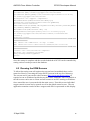
Once started the user is presented with the main screen. From this screen individual
stepper control screens can be opened as well as the global control screen. The test
application contains records for three steppers and each is represented on this display.
15 April 2009
8
ANC350 Piezo Motion Controller
EPICS Developers Manual
Figure 1 Main edl screen
Clicking on the global button opens the global parameters screen.
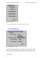
6.3 Global EDM Screen
Figure 2 Global parameters screen
This contains an input for altering the static voltage. This is the reference voltage
applied to the resistive readout system. The voltage can be set from 0.001 to 2.000V.
The current voltage is displayed immediately below the input. Below the voltage
15 April 2009
9
ANC350 Piezo Motion Controller
EPICS Developers Manual
indicator is another indicator displaying the temperature status. There are also buttons
to save or clear the current settings.
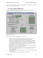
6.4 Stepper Module EDM Screen
From the main display clicking on one of the step module buttons opens the step
display for the corresponding step module.
Figure 3 Step module screen
The screen presents the following indicators and controls:
-
-
-
Position. This indicator displays the current position of the positioner
connected to the respective axis followed by the unit of this value.
Reference. Each /NUM positioner (see ANC350 manual) has its individual
reference position, a physical marker on the grating. The displayed value
corresponds to the distance between the reference position and the currently
set zero position. To get the reference position after starting the system, the
positioner has to travel over the marker only once.
Absolute Target. Entering a value here will result in the positioner moving to
this value. The move is executed immediately.
Relative Move. Entering a value in here sets up a relative movement step size.
To move the positioner by either the +ve or –ve amounts click on the
corresponding button.
Reset Position. Resets the current position to zero. This results in a loss of the
reference position.
Move To Reference. Moves the positioner to the reference.
15 April 2009
10
ANC350 Piezo Motion Controller
-
-
-
-
EPICS Developers Manual
Single Step Move. Click either of these buttons to move the positioner by a
single step.
Continuous Move. Click and hold either of these buttons to move the
positioner continuously. The positioner will move until the button is released.
Amplitude. Value for the drive voltage of this Piezo. By changing this value
the step size of the positioner can be varied. The allowed voltage values range
from 0V to 70V.
Speed. Indicates the positioner’s current travel speed.
Step Width. Indicates the positioner’s current step size.
DC Level. The applied DC voltage to the Piezo.
Frequency. Here the desired frequency can be entered with which the
positioner should move in the manual positioning mode.
Axis Status. This consists of six indicators:
o 1. Green if the positioner is connected.
o 2. Green if the axis is enabled.
o 3. Green if the positioner is referenced.
o 4. Green if there are no errors in the signal of the sensor.
o 5. This contains red text (hump detected) if the positioner reaches a
mechanical end stop.
o 6. The status of the positioner (moving or not moving).
Capacity Measure. Clicking on the Measure button determines the actual
capacitance of the connected positioner. The value is displayed in the
indicator directly below the button.
Exit. Click on this to close the screen.
7 Using the Device Support Code
The simple test application described in section 6 only presents a small subset of the
possible commands and status items available through the ethernet interface of the
ANC350 motion controller. Application developers are likely to want to create their
own databases of records; this section explains what is required to use the device
support for the ANC350.
7.1 Configuration of EPICS Records and Application
The ANC350 uses only long values when writing to and reading from its memory
locations. Therefore only two record types are required to use the device support;
they are the longin and longout record types. Longin records are used to request data
from the controller and Longout records are used to issue commands.
To set up a record for use with the ANC350 ensure the devAnc350.dbd file has been
included in the build. Set the DTYP field of the record to “ANC350”. Then the OUT
or INP links need to be configured with the following information:
-
Port Name. This must be the same name that is set in call into asyn in the
startup script (see below). This is used by the asyn layer to ensure the record
attempts communication with the correct controller.
15 April 2009
11
ANC350 Piezo Motion Controller
-
-
EPICS Developers Manual
Signal Number. This is either the number of the axis for axis specific
commands/requests, or zero for global commands/requests. It must be
prefixed with the letter ‘S’.
Memory Address. This is a hexadecimal format number that represents the
location in the ANC350 that should be written to/read from. A complete
listing of the locations and their description can be found in Appendix A.
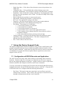
As an example, to read the current position of axis 0 you would use a Longin record
and could set the INP link to
@$(PORT) S0 0x0415
$(PORT) would need to be replaced with the name of the port created through asyn
registration.
Two template database files are included with the device support code and they
present many examples of the use of Longin and Longout records to read and set the
data inside the ANC350.
Figure 4 Reading the position and reference position from the ANC350
As well as setting up the necessary records there are some libraries that need to be
added into the source Makefile of the application (found in the directory
<appName>/src/ ). Figure 5 shows the complete source Makefile used for the test
application supplied with the ANC350 device support code.
TOP=../..
include $(TOP)/configure/CONFIG
#----------------------------------------
15 April 2009
12
ANC350 Piezo Motion Controller
EPICS Developers Manual
# ADD MACRO DEFINITIONS AFTER THIS LINE
#=============================
#=============================
# build an ioc application
PROD_IOC = ancTest350
DBD += ancTest350.dbd
# ancTest350.dbd will be made up from these files:
ancTest350_DBD += base.dbd
ancTest350_DBD += asyn.dbd
ancTest350_DBD += drvAsynIPPort.dbd
ancTest350_DBD += devAnc350.dbd
# <name>_registerRecordDeviceDriver.cpp will be created from
<name>.dbd
ancTest350_SRCS += ancTest350_registerRecordDeviceDriver.cpp
ancTest350_SRCS_DEFAULT += ancTest350Main.cpp
ancTest350_SRCS_vxWorks += -nil#The following adds support from base/src/vxWorks
ancTest350_OBJS_vxWorks += $(EPICS_BASE_BIN)/vxComLibrary
# Include the following libraries in the build
ancTest350_LIBS += asyn
ancTest350_LIBS += anc350
ancTest350_LIBS += $(EPICS_BASE_IOC_LIBS)
#===========================
include $(TOP)/configure/RULES
#---------------------------------------# ADD RULES AFTER THIS LINE
Figure 5 Source Makefile for ANC350 test application
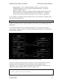
Finally, an asyn IP port must be configured at startup to connect to the ANC350
device; for this the IP address and port number of the device must be known. For the
test application the startup script is shown below.
#!../../bin/linux-x86/ancTest350
< envPaths
cd ${TOP}
## Register all support components
dbLoadDatabase("dbd/ancTest350.dbd",0,0)
ancTest350_registerRecordDeviceDriver(pdbbase)
## Load record instances
dbLoadRecords("db/ancTest.db", "")
15 April 2009
13
ANC350 Piezo Motion Controller
EPICS Developers Manual
drvAsynIPPortConfigure("IP1","10.2.2.71:2101",0,0,0)
cd ${TOP}/iocBoot/${IOC}
iocInit()
Figure 6 Startup script for the ANC350 test application
The drvAsynIPPortConfigure function call sets up the asyn port. For detailed
information see the asyn manual ([RD4]). The first argument supplied is the name of
the port; this defines the port name that should be used in all longin and longout
record INP and OUT fields. The second argument is a string that contains the IP an
address and port number to connect to. A colon separates these. The next argument
is the priority; a value of 0 indicates the use of epicsThreadPriorityMedium. The next
argument is the “auto connect” argument and a value of 0 here ensures the asyn layer
automatically connects to the port. The last argument is the noProcessEos argument.
These arguments can of course be configured as required.
15 April 2009
14
ANC350 Piezo Motion Controller
EPICS Developers Manual
8 Motor Record Support
This section deals with using the motor record to drive individual axes on the ANC
350. When creating a new application ensure the asyn, motor and anc350 modules
are all included in the configure/RELEASE file. To initialise the anc350 module the
following lines should be added to the startup script (st.cmd).
drvAsynIPPortConfigure("IP1","10.2.2.71:2101","0","0","0")
anc350AsynMotorCreate("IP1","0","0","1")
drvAsynMotorConfigure("ANC1", "anc350AsynMotor","0","1")
The first line configures the asyn layer to communicate with the ANC 350 over an
ethernet connection. This requires a name for the connection, followed by the IP
address and port number of the ANC hardware. After this there are some
configuration parameters that can be left at zero. For a full description of this
function call see the asyn driver manual [RD4].
The second line creates the ANC 350 specific device driver. Its first argument must
be the same name supplied to the previous function call. The address and card
number follow this. Finally the number of axes should be supplied to this call. In the
example above the device has been created with only a single axis.
The third and final call required sets up the motor record device support layer for the
motor record. The first parameter can be any name assigned to this device (the name
is used in the motor record itself, see below). The next parameter must be
“anc350AsynMotor”. This ensures the motor device support uses the ANC 350 driver
functions to attempt communications with the axes. The final two parameters
supplied to this function call are the card number and the number of axes.
8.1 Motor Record Database Configuration
To add motor records to a database in the application simply add an entry to a suitable
substitutions file that makes use of the motor record template. Foe example:
file ${MOTOR}/db/basic_asyn_motor.db {
pattern
{P,
M,
DESC, DTYP, DIR, VELO, VBAS, ACCL, BDST, BVEL,
BACC, PORT, ADDR, MRES, PREC, EGU, DHLM, DLLM, INIT}
{T1:, M1, Desc, asynMotor, 0,
300.0, 50.0, 1.0, 0.0,
0.0, 0.0, ANC1, 0,
0.001, 3,
um, 5000.0, -3000.0,
0}
}
The example substitution file above resulted in the following motor record
record(motor,"T1:M1")
{
field(DESC,"Desc")
field(DTYP,"asynMotor")
field(DIR,"0")
field(VELO,"300.0")
15 April 2009
15
ANC350 Piezo Motion Controller
EPICS Developers Manual
field(VBAS,"50.0")
field(ACCL,"1.0")
field(BDST,"0.0")
field(BVEL,"0.0")
field(BACC,"0.0")
field(OUT,"@asyn(ANC1,0)")
field(MRES,"0.001")
field(PREC,"3")
field(EGU,"um")
field(DHLM,"5000.0")
field(DLLM,"-3000.0")
field(INIT,"0")
field(TWV,"1")
}
The most important field is the “OUT” field. This must be set to point to the ANC
350 motor support. This is achieved by setting the value to ’@asyn(ANC1,0)’. The
ANC1 should match the name defined in the startup script and the number after this
represents the axis number (from 0 to n-1 axes).
Other motor record configuration is beyond the scope of this document: for further
details, consult the documentation [RD5].
8.2 Using the Motor Record with the ANC350
Specific features available when using the ANC350 with the motor record include the
following:
Velocity. Changing the velocity will result in a change to the frequency of the
axis. All axes are always driven in speed closed loop mode and so the change
in frequency effectively changes the velocity.
Jog. The motor can be jogged at a constant velocity in either direction.
Move. Absolute and relative moves can be made.
Referencing. The motor can be referenced. This will result in the axis
searching for its reference mark. Once found the axis will stop moving and its
position reset to zero. It is important to note that the ANC 350 hardware does
not reset the actual count value for the device to zero when it crosses its
reference mark: it simply remembers the count value at that position. The
ANC 350 motor record support internally subtracts this saved reference
position value from the actual value once the homing procedure is completed,
ensuring that the position is always zero whenever the axis is positioned at the
reference mark.
Units. The motor record described above is set up to use um as the default
unit. If the units were changed within the ANC controller then the motor
record would need to be updated accordingly (EGU, PREC, MRES).
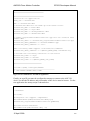
The figure below shows an example of a motor record running with an ANC 350
controller with a single axis.
15 April 2009
16
ANC350 Piezo Motion Controller
EPICS Developers Manual
Figure 7 Motor record control screen example.
15 April 2009
17
ANC350 Piezo Motion Controller
Appendix A.
Locations
EPICS Developers Manual
Commands And Status Memory
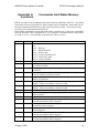
Below is a table of all commands and status locations within the ANC350. Any listed
below that do not specify units are either simple on/off commands. Items that rely on
the unit command (0x041D) have their units specified as [unit]. These units can be
set by the unit command described below.
Most simple commands operate when the value is supplied as 1, and some commands
turn off when the value is supplied as 0. For example, a continuous move starts when
its value is set to 1, and will only stop when the value is set to 0.
Location
0x0404
Global
0x0560
0x0415
x
0x0516
0x0407
0x0517
0x0441
0x0442
0x044F
0x0408
0x0518
0x040D
0x0418
0x0444
0x0410
0x0411
15 April 2009
Description
Read only. Provides information about the current states of an
axis.
Bit 0 – Moving
Bit 1 – Hump detected
Bit 8 – Sensor error
Bit 10 – Sensor disconnected
Bit 11 – Reference valid
Bit 12 – Sensor disable
Temperature status. Value of 0 indicates temperature problem.
Read only. Position of a specific axis ([unit]). Value is scaled
by a factor of 1000.
Read only. Count of rotations for position in case of rotator as
positioner.
Read only. Reference position of the appropriate axis ([unit]).
Value is scaled by a factor of 1000.
Read only. Count of rotations for reference position in case of
rotator as positioner.
Read only. Minimum position for position limited positioners
([unit]). Value is scaled by a factor of 1000.
Read only. Maximum position for position limited positioners
([unit]). Value is scaled by a factor of 1000.
Executes a reset of the position.
Defines the target position ([unit]). Value should be scaled by a
factor of 1000.
Defines the count of rotations for the target position.
Starts approach to the absolute target position (0x0408).
Previous movement will be stopped.
Starts approach to a relative target position (0x0408). Previous
movement will be stopped.
Starts approach to the reference position. Previous movement
will be stopped.
Starts a one step position update in the forward direction.
Previous movement will be stopped.
Starts a one step position update in the backwards direction.
Previous movement will be stopped.
18
ANC350 Piezo Motion Controller
0x040E
0x040F
0x0400
0x0542
0x0549
0x0514
0x0401
0x0447
0x051E
0x0569
0x0526
0x050C
0x0530
0x0531
0x0532
0x0533
0x0534
0x0535
0x0568
0x0561
0x0563
0x0562
0x0554
0x054B
0x054C
0x054D
0x054E
0x054F
0x0551
0x0553
0x0544
0x0545
0x053F
0x0540
0x053D
0x053A
0x0539
15 April 2009
x
x
EPICS Developers Manual
Starts a continuous move in the forward direction.
Starts a continuous move in the backward direction.
Set/read the amplitude (mV) for the positioner.
Set/read the speed of the positioner ([unit]/s). The value is
scaled by a factor of 1000.
Set/read the step width of the positioner ([unit]). The value is
scaled by a factor of 1000.
Set/read the DC voltage level (mV) of the positioner.
Set/read the frequency (Hz) of the excitation signal.
Switches the output relays of the amplifier.
Starts a capacitance measurement.
Read only. The result of the capacitance measurement.
Read/set the reference voltage (mV).
Sending a value of “1234” saves all parameters to controller
flash. Sending a value of “4321” clears all parameters from
flash.
Lower trigger threshold position ([unit]). Value is scaled by a
factor of 1000.
Upper trigger threshold position ([unit]). Value is scaled by a
factor of 1000.
Trigger polarity.
Number of assigned axis.
Epsilon ([unit]). Value is scaled by a factor of 1000.
Read only. Unit of trigger.
Switches bandwidth limitation. (Dither and scanner specific)
Switches the DC in connector. (Dither and scanner specific)
Switches the internal connection to the amplifier. (Dither and
scanner specific)
Switches the AC in connector, only valid for dither axes.
Position loop range ([unit]).
Gain of approach speed function in 1/s. The value is scaled by a
factor of 1000.
Enables approach speed function.
Positioner offset (mV).
Positioner gain ([unit]/V). The value is scaled by a factor of
1000.
Maximum amplitude (mV).
Sensor direction (0: Forward, 1: Backward).
Number of periods per chosen unit for optical sensors ([unit]).
Average factor for speed feedback.
Average factor for position feedback.
Sensitivity for speed feedback. The value is scaled by a factor
of 1000.
Sensitivity for position feedback. The value is scaled by a
factor of 1000.
Positioner speed for target approach ([unit]/s). The value is
scaled by a factor of 1000000.
Positioner direction (0: Forward, 1: Backward).
Type of sensor (0: Optical, 1: Resistive).
19
ANC350 Piezo Motion Controller
0x0559
0x055A
0x0527
0x0515
0x0452
0x0519
0x0450
0x041D
0x0558
0x044B
0x053B
0x0567
15 April 2009
EPICS Developers Manual
Minimum position of the sensor ([unit]). The value is scaled by
a factor of 1000.
Maximum position of the sensor ([unit]). The value is scaled by
a factor of 1000.
Gain for resistive transfer function ([unit]/V). The value is
scaled by a factor of 1000.
Maximum frequency for the positioner (Hz).
Positioner type (0: Positioner is linear, 1: Positioner is rotary).
Shortest way algorithm for rotary positioners.
Enables hump detection.
Sets the unit for the sensor.
0x00: mm
0x01: um
0x02: nm
0x03: pm
0x14: deg
0x15: mdeg
0x16: udeg
Sets the sensor average factor for the sensor ([unit]).
Minimum duration (ms) of holding target position for successful
target approach.
Reference offset ([unit]). The value is scaled by a factor of
1000.
Internal averaging of the sensor signal.
20