1
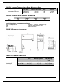
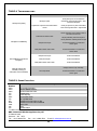
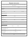
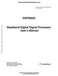
INSTALLATION, OPERATING AND SERVICING INSTRUCTION MANUAL NC SERIES COMMERCIAL NOODLE COOKER / STEAMER Model No‟s.: NC - 6 - R/S - 2RP/SP - CF - YC AGA Approval No.; 7828G B&S Commercial Kitchen Appliances Pty Ltd 57 Plateau Road Reservoir VIC 3073 AUSTRALIA Tel: +61 3 9469 4754 Fax: +61 3 94694504 Web: www.b-scka.com.au Please ensure this booklet is kept in a safe and prominent location for future reference. Owing to continual product development and improvements to its products, B&S Commercial Kitchen Appliances Pty Ltd reserves the right to change the product specifications and design without prior notice. Table of Contents Installation, operating and servicing instruction manual ................................... i NC Series Commercial Noodle Cooker / Steamer ............................................ i Product Specifications & Introduction .............................................................. 4 IMPORTANT WARNINGS ............................................................................... 5 TABLE 1: Nominal Terminal Input Rates & Injector Sizes .............. 6 TABLE 2: Standard Model General Information .............................. 6 FIGURE 1: Plumbing Connections.................................................. 6 TABLE 3: Plumbing Connections .................................................... 6 Installation Instructions .................................................................................... 7 Regulations .................................................................................................................................7 Data Label ..................................................................................................................................7 Ventilation ...................................................................................................................................7 Combustible Surfaces ................................................................................................................7 Gas Connection ..........................................................................................................................7 Pressure test point ......................................................................................................................7 Water Connection .......................................................................................................................7 Burner Adjustment ......................................................................................................................8 Before Leaving - Commissioning................................................................................................8 Operating Instructions ..................................................................................... 8 IMPORTANT WARNING! ................................................................................ 9 IMPORTANT WARNING! ................................................................................ 9 Lighting Instructions ....................................................................................................................9 Shutdown Procedure ..................................................................................................................9 Boil Out Procedure .................................................................................................................. 10 Laundry Arm Activation ........................................................................................................... 10 IMPORTANT NOTE! ..................................................................................... 10 Maintenance and Care ............................................................................................................ 10 Servicing Instructions .................................................................................... 11 Abnormal Operation ................................................................................................................ 11 Panel Removing ...................................................................................................................... 11 Controls ................................................................................................................................... 11 Thermostat............................................................................................................................... 11 Pilot Assembly ......................................................................................................................... 12 Piezo Assembly ....................................................................................................................... 12 Burners .................................................................................................................................... 12 Gas Valve ................................................................................................................................ 12 TABLE 4: Troubleshooting ............................................................ 13 TABLE 5: Spare Parts List ............................................................ 13 PRODUCT SPECIFICATIONS & INTRODUCTION Appliance Name: NC Series Noodle Cooker Manufactured By: Certificate Holder: B&S Commercial Kitchen Appliances Pty Ltd 57 Plateau Road Reservoir Victoria 3073 Tel; + 61 3 9469 4754 Fax: +61 3 9469 4504 E-mail: [email protected] Supplied in various configurations. Model Number/s: How to read model numbers; NC – 6 – R/S – 2RP/SP – CF - YC NC -6– Noodle Cooker (all models) R/S: No of round/square noodle/pasta baskets per pan 2 – two round/square baskets 4 – four round/square baskets 6 – six round/square baskets RP/SP: Number of rectangular/square pots per pan 1 – one rectangular pan 2 – two rectangular pan 3 – three rectangular pan CF – Chung Fung Steaming Tray YC – Yum Cha Steaming Tray E.G. NC-4R – 1P Is a noodle cooker with tank provisions for four round baskets and one rectangular pot. Approval Number: TBA Gas Types: Natural Gas and Propane Gas We are confident that you will be delighted with your B&S Noodle Cooker, and that it will become the backbone of your kitchen. To ensure you receive the utmost benefit from your new B&S appliance, there are two important things you can do. 1. Ensure you read this booklet carefully and carefully follow the instructions given. Ensure that this booklet is kept in a safe and prominent location for future reference. 2. Should you be unsure of any aspect of the operation/performance, servicing and installation of the appliance, please contact your B&S dealer immediately. In most instances a phone call could answer your question. NC Series (AGA No. 7828G -01) 4 February 2012 IMPORTANT WARNINGS THIS APPLIANCE SHALL ONLY BE INSTALLED/SERVICED BY AN AUTHORISED INSTALLER. THIS APPLIANCE MUST BE INSTALLED IN ACCORDANCE WITH THE SPECIFIED INSTRUCTIONS AND SPECIFICATIONS. IMPROPER INSTALLATION OR OPERATION OF THIS APPLIANCE MAY RESULT IN PRODUCT FAILURE WHICH MAY LEAD TO PROPERTY DAMAGE, PERSONAL INJURY OR DEATH. CAUTION MUST BE TAKEN WHEN OPERATING THIS APPLIANCE TO MINIMISE RISK OF FIRE. THE APPLIANCE MUST NOT BE LEFT ON UNATTENDED. REGULAR INSPECTIONS BY AN AUTHORISED SERVICE PERSON ARE STRONGLY RECOMMENDED TO ENSURE PROPER AND SAFE FUNCTIONING OF THIS APPLIANCE. AFTER ANY SERVICING OR ADJUSTING OF GAS CONNECTED COMPONENTRY, GAS LEAK TEST MUST BE CARRIED OUT TO ENSURE THERE ARE NO GAS LEAKING HAZARDS. NEVER STORE ANY FLAMMABLE LIQUIDS/VAPOURS IN THE VACINITY OF THIS APPLIANCE. NEVER SPRAY AEROSOLS IN THE VICINITY OF THIS APPLIANCE WHILE IT IS IN OPERATION. ENSURE ANY TRANSIENT PROTECTION IS REMOVED BEFORE INSTALLING THE APPLIANCE ENSURING ANY POSSIBLE DAMAGE TO THE APPLIANCE OR COMPONENTS/PARTS THAT MAY HAVE BEEN SUSTAINED DURING TRANSPORTATION IS REPORTED TO THE MANUFACTURER. ANY DAMAGE INCURRED DURING TRANSPORTATION MUST BE REPORTED IMMEADIATELY TO THE MANUFACTURER AND IT IS RECOMMENDED THE APPLIANCE IS NOT INSTALLED UNTIL FURTHER INSTRUCTIONS FROM MANUFACTURER. THIS APPLIANCE IS NOT INTENDED TO BE USED IN A MARINE ENVIRONMENT. ENSURE APPLIANCE IS INSTALLED IN A STABLE POSITION. FAILURE TO FOLLOW THE INFORMATION PROVIDED IN THIS BOOKLET WILL VOID THE B&S WARRANTY AND MAY RESULT IN DAMAGE TO EQUIPMENT OR INJURY TO PERSONNEL NC Series (AGA No. 7828G -01) 5 February 2012 TABLE 1: NOMINAL TERMINAL INPUT RATES & INJECTOR SIZES Burner Type KEEGAS KG14 Burners Gas Type Injector Size (mm) Natural Gas Propane Gas 1.75 mm 1.05 mm MJ/h per pan 58 50 Test Point Pressure 1.00 kPa 2.60 kPa TABLE 2: STANDARD MODEL GENERAL INFORMATION NC-6 Weight (kg) 100 Overall Height (mm) 1,150 Overall Depth* (mm) 840 Overall Width* (mm) 460 *Denotes minimum Overall Dimensions – Custom made appliances Height overall splashback 10750mm - 1,300mm + adjustable legs Width 1,680mm minimum with 4 pans Depth 840mm minimum FIGURE 1: PLUMBING CONNECTIONS TABLE 3: PLUMBING CONNECTIONS Water Inlet (WI) Gas Inlet (GI) Water Outlet/Waste (W) Connection Position from Floor (mm) Position from Rear of Appliance (mm) ½” Copper ¾” male BSP ¾” male BSP 330 (+/-5) 380 (+/-5) 325 (+/-5) 70 (+/-5) 65 (+/-5) 605 (+/-5) NC Series (AGA No. 7828G -01) 6 Position from LHS/RHS edge of Appliance (mm) 50 (+/-5) RHS 50 (+/-5) RHS 127 (+/-5) LHS February 2012 INSTALLATION INSTRUCTIONS REGULATIONS The appliance must be installed only by authorised persons and in accordance with the manufacturer‟s installation instructions, local gas fitting regulations, municipal building codes, AS 5601 – Gas Installations and any other health and safety regulations, local authority, gas, electrical any other statutory regulations. DATA LABEL The data label is located on the front of the appliance. This appliance is suitable for Natural Gas and LPG. Please ensure that the gas supply matches the Data Label ensuring that the gas supply is correct for the appliance being installed and that adequate supply pressure and volume is available – refer to appliance data plate for Mj/hr consumption, injector sizes of main burners/pilots, etc. VENTILATION It is strongly recommended that the appliance is installed under an extraction hood (with a clearance of 1200mm to the grease filter). Ventilation must be in accordance with AS5601 - Gas Installations. In general, the appliance should have adequate ventilation for complete combustion of gas, proper flueing and to maintain temperature of immediate surroundings within safe limits. COMBUSTIBLE S URFACES Clearances to combustible surfaces must be in accordance with AS 5601/AG 601- Gas Installations, clause 5.12.4.5. Install on a flat/level, solid, fire resistance floor. Where the floor is not fire resistant, a fire resistant material shall be put under the appliance which shall have a fire resistance rating at least equal to that of 10mm millboard. The material shall extend at least 50mm beyond the edge of the appliance. Leave a clearance of at least 200mm between the appliance and any combustible surface. Leave clearance of at least 500mm from the front of the noodle cooker for services GAS CONNECTION The gas connection is male 3/4” BSP and is situated at the rear of the appliance below the main body frame. The inlet is to the ¾” pipe inlet located at the rear of the appliance. This appliance is available in models for fixed installation. The appliance can be connected with rigid pipe as specified in AS5601. For fixed installation models we recommend connection with 20mm copper tube and an AGA approved isolating ball valve. BEFORE CONNECTING NEW PIPE TO THIS APPLIANCE, THE PIPE MUST BE BLOWN OUT THOROUGHLY TO REMOVE ALL FOREIGN MATERIAL. FOREIGN MATERIAL IN THE BURNER AND GAS CONTROLS WILL CAUSE IMPROPER AND DANGEROUS OPERATION. Connect to gas. PRESSURE TEST POINT All appliances that are dispatched from our factory are tested and adjusted according to the specifications for the required gas type. The regulator may require adjustment to achieve required gas pressure. Check the burner pressure at the test point on the regulator. The test point pressure should be adjusted to 1.00 kPa – Natural gas or 2.60 kPa – LPG with the burners operating at maximum. WATER CONNECTION NC Series (AGA No. 7828G -01) 7 February 2012 The water connection is 15mm copper and is situated at the rear of the appliance below the main body frame. The number of water inlets varies to client‟s particular needs. Water isolation valves are fitted to all water inlets. Ensure water is flushed through before final connection. Water pressure supply to the appliance is not to exceed 500kPa. Water waste and water overflow outlet is located on the left hand side of the waste gutter of the appliance (3/4” connection). The water inlets and water drains should be connected with rigid copper pipes. We do not recommend the usage of plastic/PVC piping for connection of waste outlet. BURNER ADJUSTMENT The burners do not require any adjustments Note: If any problems are experienced in maintaining the fryer burners, your local service agent should be contacted. BEFORE LEAVING - COMMISSIONING Check all connections for gas leaks with soap and water. Do not use a naked flame for detecting leaks. Ignite the pilot and main burners as prescribed below to ensure correct operation of gas valves, burners and ignition. When satisfied with the operation of the appliance, please instruct the user on the correct method of operation. Ensure that this instruction manual is left with owner of the appliance. A. Set thermostat to lowest setting. B. Turn gas cock knob such that indicator knob points to “OFF” (solid circle) position and allow 5 minutes for any gas in combustion chamber to escape (propane gas being heavier than air, may require forced ventilation). Note: If knob is in “ON” (flame) position, turn anti-clockwise to “PILOT” (spark) position. Then depress knob and turn to “OFF” position. C. Turn gas cock knob clockwise so indicator points to “PILOT” position. D. Then light the pilot manually while depressing the gas cock knob. E. Keep knob fully depressed for thirty seconds. F. Release gas cock knob. Pilot flame should continue to burn. Observe pilot is established. If pilot goes out when knob is released, repeat steps A. to F. allowing more time for thermocouple or pilot generator to heat up. G. When pilot stays alight, operation of gas valve may be given over to thermostat by turning gas cock counter clock-wise so indicator points to “ON” position (flame). H. Set thermostat to desired temperature. In the 1. 2. 3. event the appliance fails to operate correctly, check the following; Data plate to ensure correct gas type and pressure (adjust if necessary). Injector sizes – check against data plate and installation manual. View pilot size and adjust if required. OPERATING INSTRUCTIONS WARNING! DO NOT spray aerosols in the vicinity of this appliance while it is in operation. DO NOT store or use flammable liquids or items in the vicinity of this appliance. Prior to lighting, smell the area surrounding the appliance for gas (please note that as some gas types are heavier than air, we recommend the operator to also smell the floor around the appliance) NC Series (AGA No. 7828G -01) 8 February 2012 In the event you smell gas: DO NOT light any appliance. DO NOT touch/operate any electrical switch or phone in your building. Call the local gas supplier immediately and follow their instructions IMPORTANT WARNING! ALWAYS ENSURE NOODLE COOKER PAN HAS WATER IN IT WHEN MAIN BURNERS AND PILOT LIGHT ARE ALIGHT. To ensure noodle cooker pan is clean from any contamination resulting from the appliances manufacture, shipping and installation, the noodle cooker pan must be boiled out before first use. NEVER LEAVE THE APPLIANCE UNATTENDED DURING THE BOIL-OUT PROCESS. IF THE BOIL-OUT SOLUTION OVER BOILS, IMMEDIATELY TURN THE NOODLE COOKER OFF AND LET THE SOLUTION COOL FOR A FEW MINUTES BEFORE RESUMING THE PROCESS. BEFORE LIGHTING THE NOODLE COOKER, MAKE SURE THE NOODLE COOKER IS IS “OFF” AND THE NOODLE COOKER PAN DRAIN VALVE(S) IS/ARE CLOSED. NEVER ALLOW BURNER TO OPERATE WITH THE TANK EMPTY. LIGHT ONLY WHEN THE WATER IS AT THE MINIMUM OPERATING WATER MARK LOCATED ON REAR PANEL OF PAN (WHEN LOOKING INTO PAN STANDING IN FRONT OF THE APPLIANCE). IMPORTANT WARNING! ENSURE NO OR MINIMAL AMOUNTS OF OIL AND FOODSTUFFS FALL INTO THE BURNER AREA WHILST COOKING. FAILURE TO DO SO MAY AFFECT THE EFFICIENT AND SAFE OPERATION ON THE APPLIANCE AND MAY VOID WARRANTY. LIGHTING INSTRUCTIONS A. Set thermostat to lowest setting. B. Turn gas cock knob such that indicator knob points to “OFF” (solid circle) position and allow 5 minutes for any gas in combustion chamber to escape (propane gas being heavier than air, may require forced ventilation). Note: If knob is in “ON” (flame) position, turn anti-clockwise to “PILOT” (spark) position. Then depress knob and turn to “OFF” position. C. Turn gas cock knob clockwise so indicator points to “PILOT” position. D. Then light the pilot using piezo ignitor (or manually) while depressing the gas cock knob. E. Keep knob fully depressed for thirty seconds. F. Release gas cock knob. Pilot flame should continue to burn. Observe pilot is established. If pilot goes out when knob is released, repeat steps A. to F. allowing more time for thermocouple or pilot generator to heat up. G. When pilot stays alight, operation of gas valve may be given over to thermostat by turning gas cock counter clock-wise so indicator points to “ON” position (flame). H. Set thermostat to desired temperature. SHUTDOWN PROCEDURE A. Set thermostat to lowest setting. NC Series (AGA No. 7828G -01) 9 February 2012 B. Turn gas cock knob such that indicator knob points to “OFF” (solid circle) position and allow 5 minutes for any gas in combustion chamber to escape (propane gas being heavier than air, may require forced ventilation). C. Observe pilot flame is extinguished. BOIL OUT PROCEDURE 1. Prior to lighting burner, ensure noodle cooker drain valve is closed. 2. Fill noodle cooker pan with a mixture of cold water and dishwashing detergent up to the bottom of the water level line in the pan. 3. Operate the appliance as described in LIGHTING PROCEDURE above. 4. Simmer the solution for approximately one hour and turn off main burner and allow solution to cool. 5. Add approximately 5 litres of cold water into the pan and stir. 6. Open drain valve and drain the solution into a suitable container and then clean the pot thoroughly. 7. Close drain valve and rinse the fryer pan a couple of times by filling the pan with clean water and draining. 8. Dry the pan thoroughly with a clean/dry towel. LAUNDRY A RM ACTIVATION The water tank must be filled with water whenever the burners are in use to prevent the base of the pan from buckling and distorting. To activate; 1. Locate spindle on front panel. 2. Turn spindle anti-clockwise to activate water. 3. Adjust as necessary. 4. Turn spindle clockwise to de-activate water. IMPORTANT NOTE! A SMALL AMOUNT OF TRICKLING WATER MAY BE REQUIRED TO RUN INTO THE PAN WHILST IN OPERATIONS TO ENSURE ADEQUATE WATER SUPPLY TO THE TANK, ENSURE EXCESS STARCH CREATED DURING COOKING PROCESS EXITS VIA THE OVERFLOW PIPE AND ENSURE WATER PURITY. MAINTENANCE AND CARE To ensure longevity and continued performance efficiency of you appliance, a good cleaning and maintenance program is paramount. In general the use of steel wool, abrasive cloths/cleansers/powders should not be used to clean this appliance D AILY C HECKS & S ERVICE Look for any foreign materials in burner area, leaks, damaged knobs and any other signs that the wok table is not ready and safe for operation. Inspect burner area and ensure pilots are in position near the burner, and that the pilot flame when ignited is blue in color and approximately 20-40mm in length. If fitted with thermocouple ensure pilot flame is in contact with it. Call the manufacturer if you see any problems. Always ensure that area surrounding pilot and thermocouple is clear of any fats, oils or foodstuffs. Clean the exterior surfaces of the appliance with a clean, damp cloth soaked with mild detergent to remove any food stuffs, oils, dust and any other materials. Ensure the primary water drain (located in gutter of pan) is cleared of any food stuffs during operation of the appliance and on completion of use of the appliance. Y EARLY C HECKS & S ERVICE The appliance should be inspected and adjusted periodically by a qualified service person NC Series (AGA No. 7828G -01) 10 February 2012 as part of any kitchen maintenance program. B&S recommends that this appliance is inspected at least annually by a authorized service technician as follows: o Inspect the appliance inside-out for excessive build-up of any fats, oils and foodstuffs. o Inspect that the burners and other components (i.e. pilots, thermocouples, etc.) are in good condition and functioning properly. o Inspect all gas connections for leaks and ensure all connections are tightened properly. o Ensure burner manifold pressure is in accordance with that specified on the data plate of the appliance. o Inspect all gas connections for leaks and ensure all connections are tightened properly. In case of difficulties contact B&S Commercial Kitchen Appliances Pty Ltd or their authorised service agent. SERVICING INSTRUCTIONS WARNING! Servicing shall be carried out by authorised personnel only. Failure to do so will void the B&S warranty and may result in damage to equipment or injury to personnel. Before commencing any disassembly/assembly of gas controls, please ensure the gas supply is turned off (isolated). FAILURE TO DO SO WILL VOID THE B&S WARRANTY AND MAY RESULT IN DAMAGE TO EQUIPMENT OR INJURY TO PERSONNEL ABNORMAL OPERATION Any of the following are considered to be abnormal operation and may require servicing; Incomplete ignition of burner/Burner failing to keep alight Pilot is not holding Check connection of the thermocouple to the control is not loose. Check if pilot flame is in contact with thermocouple No pilot flame Check main gas valve is in “ON” position. Ensure pilot injector is not blocked Gas valves which are difficult to turn PANEL REMOVING 1. It is not necessary to remove any side or back panels for servicing the unit. 2. To remove the front panel, it will be necessary to pull off the thermostat control knob then undo the two screws holding the panel to the front hob section. CONTROLS If gas control fails to operate, check the following; 1. The thermocouple is in the pilot flame. The thermocouple must be hot in order to generate energy to operate an electromagnetic system to lift and maintain open the control valve. 2. To do so, it is necessary to generate approximately 650 milli-volts. If not functioning correctly, the thermocouple should be replaced. 3. Check both main and safety thermostats switching systems. If thermostat is malfunctioning, it should be replaced. THERMOSTAT 1. Pull thermostat knob off and unscrew thermostat from control panel. 2. Remove control panel. 3. Remove both terminals from the thermostat. NC Series (AGA No. 7828G -01) 11 February 2012 4. Remove thermostat capillary gland and remove thermostat bulb. 5. To fit new thermostat, reverse the above procedures. PILOT ASSEMBLY 1. Undo the two screws holding the pilot bracket assembly located on the front shield behind the gas valve. 2. Gently pull the pilot assembly bracket down and outwards. 3. To change thermopile a. Undo locking screw holding thermopile to pilot assembly bracket and gently pull the thermopile down. b. Undo terminal screws on located on „TH TP‟ and „TP‟ on main gas valve. c. Replace with new thermopile and assemble in reverse order. 4. To change thermocouple a. Undo locking screw holding thermocouple to pilot assembly bracket and gently pull the thermocouple down. b. Undo thermocouple screw located in the main gas valve. c. Replace with new thermocouple and assemble in reverse order. 5. To change new pilot assembly a. Follow steps 1 and 2 b. Undo the two screws on the pilot mounting bracket and pilot bracket c. Follow procedures 3. A. and 4. A. listed above d. Remove piezo lead from piezo e. Undo pilot gas flexible tube f. Change pilot assembly over and reassemble in reverse order PIEZO ASSEMBLY 1. To change piezo ignitor a. Undo the piezo screw located on the back of the piezo ignitor located on the bottom right hand side of the main gas control b. Gently remove piezo lead from rear of piezo ignitor c. Replace piezo ignitor and replace in reverse order 2. To change piezo lead a. Gently remove piezo lead from rear of piezo igitor b. Gently remove piezo ignitor lead from pilot assembly c. Replace with new lead and assemble in reverse order. BURNERS 1. To change/service burner (ensure burner is cool to prevent injury to service person) a. Undo the wing nut(s) located on the front burner support channel. b. Gently lift the front section on an angle and pull forwards so that the rear of the burner is removed off the burner injector. c. Allow the rear section of the burner to fall outside the combustion chamber and move backwards so that burner is clear of the combustion area. d. Reassemble in reverse order. GAS VALVE 1. To remove/change/service main gas valve. a. Undo barrel union on right hand side of gas valve b. Undo flexible tube to main gas valve from burner manifold. c. Undo flexible tube from pilot assembly to main gas valve. d. Undo terminals from thermostat on the main gas valve. e. Undo thermocouple leading into main gas valve f. Remove piezo igniter as described under PIEZO ASSEMBLY 1. a. above g. Undo mounting screws on the gas valve support bracket. h. Gently remove main gas valve i. Reassemble in reverse order NC Series (AGA No. 7828G -01) 12 February 2012 TABLE 4: TROUBLESHOOTING FAULT POSSIBLE CAUSE CHECKS Blockage of pilot Check pilot injector is not blocked as described in servicing instructions – pilot and flame safeguard Adjustment of pressure from flame failure control Check gas pressure to pilot as described under servicing instructions – adjustments Pilot light not igniting Positioning of thermocouple Check connection of the thermocouple to the control is not loose. Adjust positioning of thermocouple to ensure pilot flame is hitting thermocouple Pilot light not establishing Faulty thermocouple Contact manufacturer or authorised service agent Faulty flame failure control valve Contact manufacturer or authorised service agent Faulty thermocouple Contact manufacturer Faulty Thermopile Contact manufacturer Faulty flame failure control valve Contact manufacturer Pilot established, main burner not lighting Telescopic laundry arm constantly running (on water/deck cooled wok tables) Change washers in tap assembly. Worn tap washer Contact manufacturer or authorised service agent TABLE 5: SPARE PARTS L IST Part Description Number 0569 Thermopile Generator 0590 Pilot for Millivolt Control 0580 SIT 820 Nova Gas Valve 033 Laundry Arm 010 Front Stop tap 0581 Thermostat Switch 212 ¾” M/F Ball Valve 602 Flexitube from Gas valve to pilot 602A Flexitube from Gas Vale to Manifold 036A Piezo Lead 036 Piezo 325 Noodle Basket To obtain further service information concerning this appliance, pleased contact; B&S Commercial Kitchen Appliance Pty Ltd 57 Plateau Road Reservoir VIC 3073 Tel.: + 61 3 9469 4754 Fax.: + 61 3 9469 4504 E-mail: [email protected] NC Series (AGA No. 7828G -01) 13 February 2012 STANDARD WARRANTY CONDITIONS 1. 2. 3. 4. 5. 6. 7. 8. 9. a. b. 10. 11. B&S Commercial Kitchen Appliances Pty Ltd of 57 Plateau Road, Reservoir, Victoria (hereinafter called „B&S‟) undertakes by this warranty, that B&S or its agent will pay for the cost of labour for eighteen (18) months from the date of delivery to the purchaser, and for eighteen (18) months from the date of delivery to the purchaser for the cost of parts which B&S or its agent find defective. The liability of B&S under this warranty is limited to the repair or replacement of defective goods or components. All other costs including, without limitation, cartage, carriage and installation shall be borne by the purchaser. Warranty labour is supplied free of charge during business hours (8 a.m. to 5 p.m. AEDST) Monday to Friday. Should warranty work be requested outside of our normal working hours, a labour charge will be applied equivalent to a normal hour rate, with out of hours penalty rates. Penalty rates amount must be bourne by the purchaser. Claims for non-covered parts, no faults found, travel over 100km or other items outside our standard terms and conditions will be chargeable. This warranty applies only for mainland Australia and Tasmania, and does not cover any service consequent upon accident, alterations, misuse, fire, flood or act of God. This warranty is valid only if the appliance has been installed in accordance with local regulations by a duly authorised person, and the B&S installation instructions provided with the appliance. If in doubt, please contact B&S or their representative for further information. No responsibility will be accepted for defects or damages by improper installation, for changes to the product not authorised by B&S or for the operation outside the technical specifications of the appliance. This warranty is conditional upon the appliance being used in normal commercial catering operations. This warranty is the only express warranty given by the Company. No person has authority to change or to add to these obligations and liabilities. The Company has the right to determine whether or not a fault is caused by faulty workmanship or material or that any part is defective. This warranty does not apply to any loss suffered through or resulting from the non-operation or the ineffective operation of the cooking appliance or any part of the cooking appliance. This warranty does not extend to goods and components thereof manufactured either entirely or substantially of glass or similar substances, light globes, infrared or quartz tubes and electrical controls or elements. While the goods are in custody of the seller for investigation or repair, they shall be at the risk of the purchaser and no liability shall attach to the Company, its servants or agents for any damage occasioned to, or loan of, the goods whatsoever. To obtain the benefit of this warranty, the purchaser must; complete the attached „Warranty Activation‟ form supplied with this „Warranty Conditions‟ form. give notice to the Company immediately upon it becoming aware of the alleged defect and in any event before the expiration of the said eighteen (18) month period. Nothing in this warranty, however, shall be construed as affecting any rights you may have under the Trades Practices Act or any other Commonwealth or State Legislation which gives you rights which cannot be modified or excluded by agreement. SPECIAL PROVISIONS Hi-Pacs are only covered by a three (3) month labour Warranty and twelve (12) month parts warranty as they are very sensitive to moisture and extra care must be taken. Cleaning of spark and ignition sensors is not covered by warranty. Damage caused by oils, water and foodstuffs falling into burner area will not be covered under warranty. Cleaning of burners due to blockage of burner orifices caused by foodstuffs and/or oils is not covered by warranty. Breakage of glass covers (for Yakitori / Satay Grill), pilot knobs, main gas valve handles and knee wands (on waterless wok tables) are not covered under warranty. Piezo leads and ignitors are covered by twelve (12) months parts and labour only. All service warranty requests must be authorised by B&S via an official purchase order by an authorised person. FAILURE TO RETURN WARRANTY ACTIVATION FORM WILL RESULT IN REVERSION TO STANDARD B&S SERVICE WARRANTY TERMS OF TWELVE (12) MONTHS PARTS AND TWELVE (12) MONTHS LABOUR. For any service, refer to the Company or its appointed agents B&S Commercial Kitchen Appliances Pty Ltd 57 Plateau Road Reservoir VIC 3073 Ph: + 613 9469 4754 Fax: +613 9469 4504 E-mail: [email protected] Web: www.b-scka.com.au NC Series (AGA No. 7828G -01) 14 February 2012 WARRANTY ACTIVATION The Warranty Conditions shall be void unless this form is signed by the customer and the authorised installer and returned within 14 days to B&S. *Failure to complete or provide installers licence number on this form will fail to activate warranty. Model Number: Serial Number: Date Installed: Installed by: Installers address: State: Post Code: Installers Contact Details: Installers License Number: Phone (Site): Mobile: Distributor: Distributors address: State: Post Code: Distributors Contact Details: Customer: Customers address: Customer contact details: Name: Phone: Mobile: I hereby acknowledge having read the operation manual for the above mentioned (model number) appliance: Customers name(please print): Customers signature: Date: I hereby acknowledge having read and hereby accept B&S warranty terms and conditions: Customer’s Signature: Date: (or where customer is a company, the signature of a duly authorised officer) Customers Name: NC Series (AGA No. 7828G -01) 15 February 2012