1
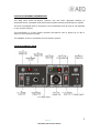
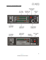
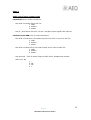
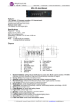
AEQ LIVE 20
Reporting unit with talkback
.
USER MANUAL
ED 07/06
LIVE 20TR USER’S MANUAL
LIVE 20TR General description
3
Front View
VHF Transmitter
UHF Receiver
Antenna connectors
Channel code
Battery low indicator
Autonomy
3
4
4
5
5
5
5
LIVE 20TR Technical specifications
VHF Transmitter
UHF Receiver
Mechanical specifications
6
6
6
6
LIVE 20T & LIVE 20R USER’S MANUAL
LIVE 20T & LIVE 20R General description
7
Front View
LIVE 20R Technical specifications
LIVE 20T Technical specifications
Starting to work
8
9
10
11, 12
ANEX 1 – Audio signal input/output codes
ANEX 2 – TX frequencies of LIVE 20T and
RX frequencies of LIVE 20TR
ANEX 3 – RX frequencies of LIVE 20R and
TX frequencies of LIVE 20TR
13
14
14
AEQ LIVE
REPORTING UNIT WITH TALKBACK
.
2
LIVE 20TR GENERAL DESCRIPTION
The AEQ LIVE 20TR full-duplex reporter unit has been designed thinking in
situations where a portable and autonomous system allows performing live reports.
The unit is equipped with 16 channels in the transmitter side as well as 16 channels
in the receiver section.
The transmitter is a high quality wireless microphone with a power up to 3W in
order to cover extensive areas.
The talkback receiver completes the full-duplex system.
LIVE 20TR FRONT VIEW
AEQ LIVE
REPORTING UNIT WITH TALKBACK
.
3
LIVE 20TR VHF TRANSMITTER
1. TX 16 CHANNEL CONNECTOR – The user can choose any of 16 channels by a
digital selector.
2. AUDIO IN CONNECTOR: By a XLR3 F connector with the following code:
1 – GND
2 – Phase +
3 – Phase –
3. Gain Potentiometer
4. Audio peak indicator LED
5. BATTERY LEVEL INDICATOR
- LOW – enough battery charge. If LOW is lighting you must replace the
batteries.
6. ANTENNA CONNECTOR (BNC) – Please check that the antenna is correctly
placed before switch on the unit.
7. Power ON/OFF.
LIVE 20TR UHF RECEIVER
8. RX 16 CHANNEL SELECTOR – The user can choose any of 16 channels by a
digital selector.
9. HEADPHONES CONNECTORS – The unit has two headphones connectors.
(1/4” and 3,5 mm)
10. TALKBACK VOLUME POTENTIOMETER – You can regulate the headphones
volume from 0 to 140mW approx. (in 16 ohms headphones)
11. ANTENNA RX CONNECTOR – TNC type.
12. POWER ON/OFF
AEQ LIVE
REPORTING UNIT WITH TALKBACK
.
4
LIVE 20TR ANTENNA CONNECTORS
•
•
VHF Transmitter: BNC connector.
UHF Receiver: TNC connector.
You must use the antennas that we enclose with the unit because this are adjusted to the frequencies.
LIVE 20TR CHANNEL CODE
CH
0
1
2
3
4
5
6
7
FREC.
1
2
3
4
5
6
7
8
CH
8
9
A
B
C
D
E
F
FREQ.
9
10
11
12
13
14
15
16
LIVE 20TR BATTERY LOW INDICATOR
It is the battery status indicator. If the led is lighting, then you must change the
batteries.
LIVE 20TR AUTONOMY
During normal (HI POWER) operation with fresh batteries you can expect more than
4 hours of continuous operation.
NOTE this unit can also be powered with a Li-Ion pack battery type DR-202 that can
be charged inside the LIVE 20TR or with the charger CH-42.
AEQ LIVE
REPORTING UNIT WITH TALKBACK
.
5
LIVE 20TR TECHNICAL SPECIFICATIONS
RADIO VHF TRANSMITTER
-Frecuency range:
-Power:
-Output impedance:
-Channels :
-Modulation:
-Spurious emissions:
-RF connector:
-Channel selection:
ON and channel change
170-250 MHz
3W
50 ohms
16 digital PLL
+/- 30KHz pre-emphasis 75us
<- 60dBc
BNC
1 digit hexadecimal encoder, delayed
AUDIO VHF TRANSMITTER
-Input:
-NR system:
-Gain control
-AF bandwidth:
-Distorsion:
-Audio connector:
-SNR:
Balanced mic and line switchable
“Silenzo” compressor limiter
50Hz/15 KHz +/- 0,5 dB
<0,3%
XLR 3 F
>85dB
RADIO UHF RECEIVER
-Frecuency range:
-Channels:
-Sensitivity:
-Demodulation:
-Input impedance:
-Spurious emissions:
-RF connector:
-Channel selection:
440-470 MHz
16 digital PLL
-112dBm / 12dB SINAD
+/-30 KHz de-emphasis 50 us
50 Ohms
<- 2nW
TNC
1 digit hexadecimal encoder
AUDIO UHF RECEIVER
-Output:
-NR system:
-AF bandwidth:
-Distorsion:
-Connector:
-SNR:
Headphones output 1,5V/8 ohm
“Silenzo” expander
50 Hz/15KHz +/- 0,5dB
<0,3%
Jack stereo ¼” and minijack 3,5 mm
>85dB
DIMENSIONS, WEIGHT AND CONTROLS
-ON/OFF switch:
TX and RX
-Separate RX and TX channel connector
-Mechanized aluminium enclosure, microwave technology
-Battery status
-Audio peak
-Dimensions:
190 x 59 x182 mm
-Weight:
2,5 kgs (including batteries)
-Power:
12 alcaline batteries LR-14 or Ion/Lithium battery DR-202
type
AEQ LIVE
REPORTING UNIT WITH TALKBACK
.
6
LIVE 20T & LIVE 20R GENERAL DESCRIPTION
The system LIVE 20T & LIVE 20R is a full duplex portable station including a
“PROGRAM” diversity receiver LIVE 20R and a “TALKBACK” transmitter LIVE 20R.
Together with the LIVE 20TR, they conforms a complete reporter system.
LIVE 20T
The talkback transmitter is 16 channels, usually pre-programmed in the 400-500
MHz band which could be reprogrammed by the user with very simple PC running
software.
The frequency deviation depends on local regulations and must be aligned in
factory.
The audio signal is processed with a compressor and limiter.
LIVE 20R
The RD-42 is a true diversity receiver containing two complete receivers with a low
noise amp in each front end.
The audio processing consist in a very advanced expander that works together with
the compressor-limiter equipped in the STAR-42, allowing a very high SNR.
The frequency selection is made by the front panel selector among 16 preprogrammed channels.
The channel space as well as the centre frequency can be PC programmed by the
user.
The standard frequency deviation is +/- 30 KHz but any value could be ordered and
must be the factory aligned.
AEQ LIVE
REPORTING UNIT WITH TALKBACK
.
7
LIVE 20T & LIVE 20R FRONT VIEW
AEQ LIVE
REPORTING UNIT WITH TALKBACK
.
8
LIVE 20R TECHNICAL SPECIFICATIONS
RADIO
Frecuency range:
Sensitivity:
Channels:
Ch Selector:
Demodulation:
Input impedance:
Spurious emissions:
RF input connectors:
174-187 MHz
-112dBm / 12dB SINAD
16, PLL digital.
1 digit hexadecimal encoder
+/- 30 Khz de-emphasis 75us
50 Ohm
< -2nW
BNC (2)
AUDIO
Audio Output:
NR system:
DSP:
Monitor Control:
AF bandwidth:
Distorsion:
Audio connector:
SNR:
Líne/600 ohm/balanced(rear).
Headphones(front)
“Silenzo” Expander
32 bit (option)
Front Panel
50 Hz/15 KHz +/- 0,5 dB
<0,3%
XLR3, M (rear) jack stereo 1/4” (front)
>100 dB
INDICATORS
RSSI (90dB range)
VU-meter
1 digit hexadecimal encoder display
DSP enable
Diversity A/B
GENERAL AND CONTROL
ON/OFF Switch
Channel encoder control
Monitor volume and Squelch
Aluminium enclosure
Power:
Dimensions:
Weight:
Power connector:
External 12V DC / 0,25 A
300x145x40 mm (1/3 rack)
0,9 Kg
XLR4 F
RS 232 bus for reprogramming.
AEQ LIVE
REPORTING UNIT WITH TALKBACK
.
9
LIVE 20T TECHNICAL SPECIFICATIONS
RADIO
Frecuency range:
Power:
Channels:
Ch Selector:
Modulation:
Output impedance:
Spurious emissions:
RF output connector:
174-500 MHz
Up to 5W, 100%, duty cycle, delayed ON.
16, PLL digital.
1 digit hexadecimal encoder, delayed
+/- 30 Khz pre-emphasis 50us
50 Ohm
< -65 dBc
Type N
AUDIO
Audio Input:
NR system:
Gain Control:
AF bandwidth:
Distorsion:
Audio connector:
SNR:
Mic/líne sel.
“Silenzo”Compressor limiter
Front Panel
50 Hz/15 KHz +/- 0,5 dB
<0,3%
XLR3 F
>85 dB
INDICATORS
VU-meter
Audio Peak
DSP enable
Channel display
GENERAL
ON/OFF Switch
Mic/line Switch
Channel encoder control
Audio Gain control
Power:
Dimensions:
Weight:
Power connector:
RS 232 bus for reprogramming.
external 12V DC / 2 A
300x145x40 mm (1/3 rack)
0,8 Kg
XLR4 F
AEQ LIVE
REPORTING UNIT WITH TALKBACK
.
10
STARTING TO WORK WITH THE LIVE 20TR
•
Connect the antennas.
•
To get the best transmission range, we recommend putting the TX antenna
on the shoulder adaptor (option).
•
Check the batteries. The user must put a new battery pack totally charged
before a new work.
•
Select the correct TX channel and RX channels.
•
Adjust the input audio level.
•
Check the output audio level in the headphones.
STARTING TO WORK WITH THE LIVE 20T & LIVE 20R
•
Connect the antennas. The TX antenna will be a magnetic base type (with
the system) or GP-70 or colineal type (optional)
•
In any case we recommend using high quality coaxial cable of impedance 50
ohms.
•
For the RX the user will have two magnetic base antennas (BM-150 type).
•
Switch on the power supply and connect it to the LIVE 20T and LIVE 20R
back connectors.
•
Select the TX and the RX channel.
•
Check the TX power ON
AEQ LIVE
REPORTING UNIT WITH TALKBACK
.
11
STARTING TO WORK WITH THE WHOLE SYSTEM
1. Connect all the antennas (LIVE 20TR, LIVE 20T & LIVE 20R). Be careful to
put all the magnetic antennas on a magnetic material in order to have a
good ground plane. The minimum separation must be 2 meters between one
to each other.
2. Insert the battery in the LIVE 20TR. We suggest charging totally the battery
before the use.
3. Choose, of course, the same channel at the LIVE 20R and the TX of the LIVE
20TR and also do the same with the LIVE 20T and the RX of the LIVE 20TR.
4. Adjust the audio in the LIVE 20TR and the LIVE 20T
5. Connect the LIVE 20R to a mixing desk or just listen with headphones.
6. Adjust for a proper listening level in your headphones (LIVE 20TR)
7. Now, you can send audio in both ways and test if you has the right program
on the LIVE 20R and the proper talkback on the RX of the LIVE 20TR
AEQ LIVE
REPORTING UNIT WITH TALKBACK
.
12
ANEX 1
Audio signal input/output codes
LIVE 20TR have 3 audio connectors:
-
One XLR-3 to audio input VHF TX:
1. GND
2. Phase +
3. Phase -
-
One ¼” jack stereo and one 3,5 mm. minijack output signal from UHF RX
LIVE 20T/LIVE 20R have 3 audio connectors:
-
One XLR-3 F that this is the audio input at line level or micro to UHF TX:
1. GND
2. Phase +
3. Phase -
-
One XLR-3 M that this is the audio output at line level of VHF RX:
1. GND
2. Phase +
3. Phase -
-
One stereo ¼” Jack to audio output of VHF RX for headphones monitor.
-
XLR4 12 V DC.
1.
2.
3.
4.
NC
NC
+
AEQ LIVE
REPORTING UNIT WITH TALKBACK
.
13
ANEX 2
TX frequencies of LIVE 20T and RX frequencies of LIVE 20TR:
ANEX 3
RX frequencies of LIVE 20R and TX frequencies of LIVE 20TR:
AEQ LIVE
REPORTING UNIT WITH TALKBACK
.
14