1
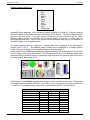
InstantHMI 5.0
HMI/SCADA Software for Windows PC, Windows CE and PDA
(Pocket PC, Windows Mobile, Smart Phone, Palm OS) Platforms
Part# 51Man-xx, Version 5.0.14, 2008 Jul 20.
Copyright © 2000-2008 Software Horizons Inc., 100 Treble Cove Road, N Billerica, MA 01862, USA.
All rights reserved. No part of this manual may be reproduced or transmitted in any form or by any means without
the written permission of Software Horizons Inc.
Software Horizons and InstantHMI are registered trademarks, and InstantPanel, OI-Widgets are trademarks of
Software Horizons Inc. All other trademarks belong to the respective companies.
InstantHMI® - Choose your flavor. Enjoy the benefits.
Welcome to InstantHMI version 5.0, your multi-platform HMI solution, which reinforces our motto 'Simplify'
while building upon the success of InstantHMI 4.x to accomplish our vision: ‘Design Once, Deploy Anywhere’
platform scalable new generation HMI Technology for Windows PC, Windows CE (touch panels), PDA (Pocket
PC and Palm OS) and Smart Phone Platforms. In late 1999, we embarked upon the challenge of meeting this
vision. The new InstantHMI architecture was first released in version 1.x for PDAs (Palm and Pocket PC) and
in version 2.0 functional differences between the two PDA-OS implementations were, for all practical
purposes, eliminated. Our legacy HMI technology (OI-2000) continued to support Windows PC platforms.
The elegance and strength of the InstantHMI architecture was realized in version 4.0, which was capable of
supporting all the powerful and convenient features of earlier PC-based HMI-technology (OI-2000 3.50 for
Windows), as well as infusing the ‘Instant On – Ready to Go’ philosophy incorporated in the Version 2.0 for
PDA platforms. InstantHMI 4.0 incorporated the new Windows PC based LaunchPad Development System,
which you use to design your Project screens and Tag database that can then be deployed on any of the
target platforms which has an installed InstantHMI Runtime engine. The LaunchPad allows pre-testing of the
tags and screens on the Windows PC platform before deploying on the target PC, CE or PDA platform.
InstantHMI 5.0 reinforces our motto 'Simplify' while furthering our objective of providing ‘Anytime, Anywhere’
connectivity to process and machine control information taking advantage of the unique features of the various
platforms: mobility, wireless connectivity, barcoding and GPS capabilities of PDAs, compactness and power of
CE platforms, and full-featured functionality of PC platforms.
Why Upgrade to InstantHMI 5.0: Our legacy technology, OI-2000 for Windows has been retired. Users of OI2000 3.50 can easily transfer their PC projects to the new InstantHMI 5.0 framework and enjoy all the new
functionality, including access to the PDA platform deployment. Users of earlier versions of InstantHMI can
transfer their project (Tag databases, screens, etc.) easily to InstantHMI 5.0 framework and take advantage of
all the new functionality, including powerful new object assemblies for screen development, 'Simpler is Better'
architecture and numerous enhancements.
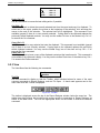
Benefit from Important InstantHMI features (including the following):
•
•
•
•
•
•
•
•
•
•
•
•
•
•
•
•
•
•
•
•
The screen data object display format is independent of the raw data of the tag object in the Tag Database. You can
view data from a data source in different formats on one or more screens.
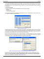
Use enhanced Data Table Viewer in Screen Designer to monitor/modify controller tags and transfer pre-tested tags to
the Tag database (5.0.9).
Real Time and Historic Trend Plots that can be viewed in the PDA as well as PC (4.1)
Project Protection to help OEMs and Designers to prevent screen/tag modifications (4.1)
Alarm Logging as an Object (4.1)
Enhanced Tanks, Scales, Gauges, Faders, Knobs, and other widgets (4.1)
Print Screen feature to help operator create an 'Instant Runtime Status Dump' (4.1)
The Title Bar, Menu Bar, and Status Bar may be hidden at Runtime. A right click on screen allows the screen view to
include or exclude Title/Menu/Status bars (4.1, 4.2).
Widget and Plot objects allow negative and floating point values and labels (4.2)
InstantHMI software release is made available in Unicode as well as non-Unicode versions (4.2, 5.0).
Scripting tool is enhanced. You may use any (long) variable names for local and global variables (4.2, 5.0).
OLE, COM, ActiveX component support enhanced with improved user interface and functionality (4.2, 5.0)
'Simpler is Better' architecture and related enhancements (5.0)
'Tag Alias' feature and related enhancements (5.0.1- 5.0.5)
Use dynamic runtime association of Object Assemblies with multiple Tag Groups for streamlined monitoring of similar
sub-systems (5.0.5 - 5.0.9)
Use Watch Lists in Runtime to monitor/modify controller tags from different groups (5.0.5 - 5.0.8). A single watch list (in
an object assembly) can provide a comprehensive, yet simple, interface to let you monitor thousands of tag variables,
for dozens of controller stations in a very concise and familiar manner (like browsing through the Controller user
manuals).
New Project Wizard guides you step by step to quickly create and run a new project in minutes (5.0.9).
Enhanced Buttons (Widget, Windows or Bitmap) with settable colors and font as well as testable preview (5.0.10).
Enhanced Widgets (LEDs, Gauge, Knob, etc.) with many settable properties etc. as well as testable preview (5.0.14).
All known and customer reported bugs have been fixed and many feature requests implemented (5.0.14).
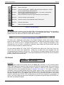
We appreciate the feedback from our valued customers. With these powerful enhancements and 'Simpler is
Better' architecture InstantHMI 5.0 hopes to be your preferred HMI/SCADA solution.
The InstantHMI 5.0 Development Team
®
SOFTWARE HORIZONS INC. InstantHMI PROGRAM LICENSE AGREEMENT
YOU SHOULD CAREFULLY READ THE FOLLOWING TERMS AND CONDITIONS BEFORE USING THIS PACKAGE. IF YOU
DO NOT AGREE WITH THEM, PROMPTLY RETURN THE PACKAGE UNUSED WITHIN 10 DAYS AND YOUR MONEY WILL
BE REFUNDED. USING THIS PACKAGE INDICATES YOUR ACCEPTANCE OF THESE TERMS AND CONDITIONS.
Software Horizons Inc. (SH) provides InstantHMI (the "Program") and licenses its use pursuant to license agreements. You
assume responsibility for the selection of the Program to achieve your intended results, and for the installation, use, and results
obtained from the Program. You may a) Install and operate the Program on a single computer. b) Transfer the Program, subject
to the terms of this license, to another party if the other party agrees to accept the terms and conditions of this Agreement. If you
transfer the Program, you must at the same time either transfer all copies whether in printed or machine-readable form to the
same party or destroy any copies not transferred.
You may not: a) use, copy, modify or transfer the Program, or any copy, in whole or in part, except as expressly provided for in
this license. b) provide or allow use of the Program in any network, time sharing, multiple CPU, or multiple-user arrangements.
c) grant sub-licenses or other rights in the Program. d) reproduce the documentation.
IF YOU TRANSFER POSSESSION OF THE PROGRAM OR ANY COPY TO ANOTHER PARTY, YOUR LICENSE IS
AUTOMATICALLY TERMINATED.
TERM: This license is effective until terminated. You may terminate it at any other time by destroying the Program together with
all copies in any form. It will also terminate upon conditions set forth elsewhere in this Agreement. You agree upon such
termination to destroy the Program together with all copies in any form. No refunds will be made on termination of license.
LIMITED WARRANTY: SH warrants the diskette(s) and computer chips on which the Program is furnished to be free from
defects in materials and workmanship under normal use for a period of ninety (90) days from the date of delivery to you as
evidenced by a copy of your receipt. However, SH does not warrant that the Program will meet your requirements or that the
operation of the Program will be uninterrupted or error free.
THE PROGRAM IS PROVIDED "AS IS" WITHOUT ANY WARRANTY, EXCEPT AS STATED ABOVE, OF ANY KIND, EITHER
EXPRESSED OR IMPLIED, INCLUDING, BUT NOT LIMITED TO THE IMPLIED WARRANTIES OF MERCHANTABILITY AND
FITNESS FOR A PARTICULAR PURPOSE. THE ENTIRE RISK AS TO THE QUALITY AND PERFORMANCE OF THE
PROGRAM IS WITH YOU.
LIMITATIONS OF REMEDIES: SH's entire liability and your exclusive remedy shall be: the replacement of any diskette(s)
and/or chips not meeting SH's "Limited Warranty" and which is returned to SH with a copy of your receipt.
IN NO EVENT WILL SH BE LIABLE TO YOU FOR DAMAGES, INCLUDING ANY LOST PROFITS, LOST MONIES OR OTHER
INCIDENTAL OR CONSEQUENTIAL DAMAGES ARISING OUT OF THE USE OR INABILITY TO USE (INCLUDING BUT NOT
LIMITED TO LOSS OF DATA OR DATA BEING RENDERED INACCURATE OR LOSSES SUSTAINED BY THIRD PARTIES
OR A FAILURE OF THE PROGRAM TO OPERATE WITH PROGRAMS NOT DISTRIBUTED BY SH) SUCH PROGRAM EVEN
IF SH HAS BEEN ADVISED OF THE POSSIBILITY OF SUCH DAMAGES, OR FOR ANY CLAIM BY ANY OTHER PARTY.
SOME STATES DO NOT ALLOW THE LIMITATION OR EXCLUSION OF LIABILITY FOR INCIDENTAL OR CONSEQUENTIAL
DAMAGES OR IMPLIED WARRANTIES SO THE ABOVE LIMITATION OR EXCLUSION MAY NOT, IN WHOLE OR IN PART,
APPLY TO YOU.
GENERAL: You may not sublicense, assign or transfer this license or the Program except as expressly provided in this
Agreement. Any attempt otherwise to sublicense, assign, or transfer any of the rights, duties or obligations hereunder is void.
This Agreement shall be governed by the laws of the Commonwealth of Massachusetts.
Should you have any questions concerning this Agreement, you may contact SH by writing to Software Horizons Inc., 100
Treble Cove Road, N. Billerica, Massachusetts 01862.
YOU ACKNOWLEDGE THAT YOU HAVE READ THIS AGREEMENT, UNDERSTAND IT AND AGREE TO BE BOUND BY ITS
TERMS AND CONDITIONS. YOU FURTHER AGREE THAT IT IS THE COMPLETE AND EXCLUSIVE STATEMENT OF THE
AGREEMENT BETWEEN US, WHICH SUPERSEDES ANY PROPOSAL OR PRIOR AGREEMENT, ORAL OR WRITTEN, AND
ANY OTHER COMMUNICATIONS BETWEEN YOU AND SH RELATING TO THE SUBJECT MATTER OF THIS AGREEMENT.
U.S. Government Restricted Rights. The SOFTWARE and documentation are provided with RESTRICTED RIGHTS. Use,
duplication, or disclosure by the United States Government is subject to restrictions as set forth in subparagraph (c)(1)(ii) of The
Rights in Technical Data and Computer Software clause at DFARS 252.227-7013 or subparagraphs (c)(1) and (2) of the
Commercial Computer Software--Restricted Rights at 48 CFR 52.227-19, as applicable. Manufacturer is Software Horizons
Inc., 100 Treble Cove Road, N. Billerica, MA 01862, USA.
Table of Contents
1 InstantHMI® for your Application................................................................................................................................... 1-1
1.1 Introduction ............................................................................................................................................................ 1-1
1.2 InstantHMI Design and Runtime Platforms ............................................................................................................ 1-1
1.3 InstantHMI Overview ............................................................................................................................................. 1-3
1.4 Get Started Immediately ........................................................................................................................................ 1-5
2 LaunchPad Development System................................................................................................................................. 2-1
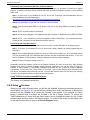
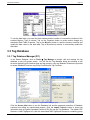
2.1 Help ....................................................................................................................................................................... 2-2
2.2 Login...................................................................................................................................................................... 2-3
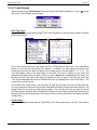
2.3 Design ................................................................................................................................................................... 2-5
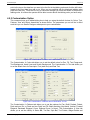
2.3.1 Design Æ Screens .......................................................................................................................................... 2-5
2.3.2 Design Æ Screen Æ Troubleshoot Scripts ..................................................................................................... 2-6
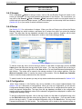
2.3.3 Design Æ Reports .......................................................................................................................................... 2-7
2.3.4 Design Æ Tags ............................................................................................................................................... 2-7
2.3.5 Design Æ Data Sources ................................................................................................................................. 2-9
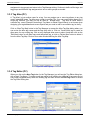
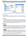
2.4 Setup ..................................................................................................................................................................... 2-10
2.4.1 Setup Æ Project (New, Remove, Platform)..................................................................................................... 2-12
2.4.2 Setup Æ Project Æ Users............................................................................................................................... 2-14
2.4.3 Setup Æ Project Æ Protect ............................................................................................................................. 2-15
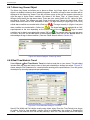
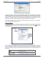
2.4.4 Setup Æ Project Æ Deploy ............................................................................................................................. 2-17
2.4.5 Setup Æ Screens............................................................................................................................................ 2-18
2.4.6 Setup Æ Reports ............................................................................................................................................ 2-19
2.4.7 Setup Æ Special Tags .................................................................................................................................... 2-19
2.5 Run ........................................................................................................................................................................ 2-20
2.5.1 Project Overview............................................................................................................................................. 2-21
2.5.2 Project Runtime Options ................................................................................................................................. 2-21
2.5.3 Run/Emulate Project....................................................................................................................................... 2-21
2.5.4 Project Reports ............................................................................................................................................... 2-22
2.6 Exit......................................................................................................................................................................... 2-24
3 Data Bases ................................................................................................................................................................... 3-1
3.1 Data Sources ......................................................................................................................................................... 3-1
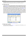
3.2 Data Table Viewer ................................................................................................................................................. 3-2
3.2.1 Data Viewer (PC)............................................................................................................................................ 3-3
3.2.2 Data Table Tool (PDA) ................................................................................................................................... 3-3
3.3 Tag Database ........................................................................................................................................................ 3-4
3.3.1 Tag Database Manager (PC).......................................................................................................................... 3-4
3.3.2 Tag Group Functions (PC)............................................................................................................................. 3-5
3.3.3 Tag Alias (PC) ................................................................................................................................................ 3-6
3.3.4 Tag Editor (PC)............................................................................................................................................... 3-6
3.3.5 Tag Database Manager (PDAs)...................................................................................................................... 3-12
3.3.6 Tag Group Functions (PDAs).......................................................................................................................... 3-13
3.3.7 Tag Editor (PDAs)........................................................................................................................................... 3-14
3.4 Message Database................................................................................................................................................ 3-17
3.4.1 Message Database Manager (PC) ................................................................................................................. 3-18
3.4.2 Message Database Manager (PDAs) ............................................................................................................. 3-19
3.5 Bitmaps.................................................................................................................................................................. 3-20
3.5.1 Bitmap (Screen Capture) Utility ...................................................................................................................... 3-20
3.5.2 Bitmap Groups (PC) ....................................................................................................................................... 3-21
3.5.3 Bitmap Groups (PDAs) ................................................................................................................................... 3-21
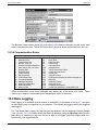
3.6 Recipes and Configurations................................................................................................................................... 3-21
3.6.1 Recipes (PC) .................................................................................................................................................. 3-22
3.6.2 Recipes (PDA) ................................................................................................................................................ 3-22
3.6.3 Configurations (PC) ........................................................................................................................................ 3-23
3.6.4 Configurations (PDA) ...................................................................................................................................... 3-24
3.6.5 Examples ........................................................................................................................................................ 3-25
3.7 Data Logs .............................................................................................................................................................. 3-28
3.7.1 Time Based Data Logging .............................................................................................................................. 3-28
3.7.2 Event Triggered Data Logging ........................................................................................................................ 3-29
3.7.3 Viewing Logged Data...................................................................................................................................... 3-30
3.8 Database Info ........................................................................................................................................................ 3-30
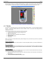
4 Screen Designer ........................................................................................................................................................... 4-1
4.1 Getting Started....................................................................................................................................................... 4-1
4.1.1 Title Bar .......................................................................................................................................................... 4-2
4.1.2 Status Bar ....................................................................................................................................................... 4-3
4.1.3 Tool Bar .......................................................................................................................................................... 4-3
4.1.4 Style Bar ......................................................................................................................................................... 4-4
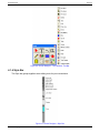
4.1.5 Menu Bar (Main Menu) ................................................................................................................................... 4-5
4.1.6 Creating Application Screens.......................................................................................................................... 4-5
4.2 File......................................................................................................................................................................... 4-6
4.3 Edit ........................................................................................................................................................................ 4-8
4.3.1 Redraw ........................................................................................................................................................... 4-9
4.3.2 UnDelete Object (Ctrl + A) .............................................................................................................................. 4-9
4.3.3 Move Object.................................................................................................................................................... 4-9
4.3.4 Copy Object .................................................................................................................................................... 4-9
4.3.5 Delete Object .................................................................................................................................................. 4-9
4.3.6 Make Object Assembly ................................................................................................................................... 4-9
4.3.7 Break Object Assembly .................................................................................................................................. 4-12
4.3.8 Arrange Objects.............................................................................................................................................. 4-13
4.4 View....................................................................................................................................................................... 4-13
4.5 Tag Data................................................................................................................................................................ 4-14
4.6 Objects .................................................................................................................................................................. 4-14
4.6.1 Static Objects.................................................................................................................................................. 4-14
4.6.2 Data Object..................................................................................................................................................... 4-19
4.6.3 Watch List ....................................................................................................................................................... 4-20
4.6.4 Object Assembly............................................................................................................................................. 4-21
4.6.5 Touch Zone Object ......................................................................................................................................... 4-24
4.6.6 Text Scroll Object ........................................................................................................................................... 4-25
4.6.7 Alarm Log Viewer Object ................................................................................................................................ 4-26
4.6.8 Real Time/Historic Trend ................................................................................................................................ 4-26
4.6.9 OLE Object ..................................................................................................................................................... 4-27
4.6.10 ActiveX Object .............................................................................................................................................. 4-29
4.6.11 OLE/ActiveX Verbs ....................................................................................................................................... 4-33
4.7 Format ................................................................................................................................................................... 4-34
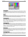
4.7.1 Patterns .......................................................................................................................................................... 4-34
4.7.2 Color ............................................................................................................................................................... 4-35
4.7.3 Font ................................................................................................................................................................ 4-37
4.8 Tools...................................................................................................................................................................... 4-37
4.9 Options .................................................................................................................................................................. 4-37
4.9.1 Tabbing Order Option ..................................................................................................................................... 4-37
4.9.2 Customization Option ..................................................................................................................................... 4-38
4.9.3 Password Option ............................................................................................................................................ 4-39
4.10 Help ..................................................................................................................................................................... 4-39
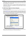
4.11 Create Data Display Object ................................................................................................................................. 4-40
4.11.1 Data Type ..................................................................................................................................................... 4-42
4.11.2 Text Data Format.......................................................................................................................................... 4-43
4.11.3 Graphic Data Format - Input Widgets ........................................................................................................... 4-45
4.11.4 Clipboard Tools............................................................................................................................................. 4-49
4.11.5 Graphic Data Format - Monitor Widgets ....................................................................................................... 4-51
4.11.6 Color and Font .............................................................................................................................................. 4-56
4.11.7 Sample Time................................................................................................................................................. 4-56
4.11.8 Script ............................................................................................................................................................ 4-57
4.11.9 Remark ......................................................................................................................................................... 4-57
4.11.10 OK and Cancel ........................................................................................................................................... 4-57
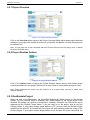
4.12 Edit Data Display Object ...................................................................................................................................... 4-57
4.13 Document Data Display Object............................................................................................................................ 4-58
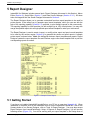
5 Report Designer............................................................................................................................................................ 5-1
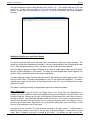
5.1 Getting Started....................................................................................................................................................... 5-1
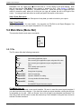
5.2 Main Menu (Menu Bar) .......................................................................................................................................... 5-3
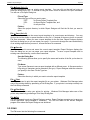
5.2.1 File.................................................................................................................................................................. 5-3
5.2.2 Edit ................................................................................................................................................................. 5-4
5.2.3 View................................................................................................................................................................ 5-5
5.2.4 Insert............................................................................................................................................................... 5-6
5.2.5 Tag Data ......................................................................................................................................................... 5-7
5.2.6 Help ................................................................................................................................................................ 5-10
5.3 Spooling................................................................................................................................................................. 5-12
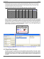
5.3.1 Naming Spool Files......................................................................................................................................... 5-12
5.3.2 Overview......................................................................................................................................................... 5-13
5.3.3 Spool Register Functions................................................................................................................................ 5-13
5.3.4 Examples ........................................................................................................................................................ 5-16
5.4 Creating Reports at Runtime ................................................................................................................................. 5-17
5.4.1 Using Reports Æ Print Menu at Runtime ........................................................................................................ 5-17
5.4.2 Using Reports Æ Spool Menu at Runtime ...................................................................................................... 5-17
5.4.3 Using Spooled Data in Printer Reports ........................................................................................................... 5-17
6 Macro Editor ................................................................................................................................................................. 6-1
6.1 Getting Started....................................................................................................................................................... 6-2
6.2 Screen/Project Macros .......................................................................................................................................... 6-2
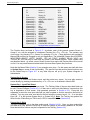
6.3 Macro Commands ................................................................................................................................................. 6-3
6.4 Macro Example...................................................................................................................................................... 6-5
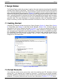
7 Script Editor .................................................................................................................................................................. 7-1
7.1 Getting Started....................................................................................................................................................... 7-1
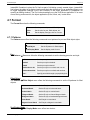
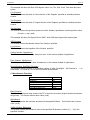
7.2 Script Elements...................................................................................................................................................... 7-1
7.2.1 Variables and Keywords ................................................................................................................................. 7-3
7.2.2 Operators........................................................................................................................................................ 7-3
7.2.3 Functions ........................................................................................................................................................ 7-3
7.2.4 Expression ...................................................................................................................................................... 7-12
7.2.5 Assignment Statement.................................................................................................................................... 7-13
7.2.6 Label and Comments...................................................................................................................................... 7-13
7.2.7 Control Statement........................................................................................................................................... 7-13
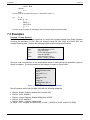
7.3 Examples ............................................................................................................................................................... 7-14
7.4 Error Messages ..................................................................................................................................................... 7-19
8 Communication Links ................................................................................................................................................... 8-1
8.1 RS-232 Signal Assignments .................................................................................................................................. 8-1
8.2 RS-232/RS-485 Serial Link using Cables .............................................................................................................. 8-1
8.3 IR Link using Infrared Kit ....................................................................................................................................... 8-2
8.4 RF-Link using RF-Kit ............................................................................................................................................. 8-3
9 Runtime Engine (PC).................................................................................................................................................... 9-1
9.1 Introduction ............................................................................................................................................................ 9-1
9.2 Your Application Step By Step............................................................................................................................... 9-2
9.2.1 'Hit the Ground Running'................................................................................................................................. 9-2
9.2.2 Methodically Design Your HMI........................................................................................................................ 9-3
9.3 Project Setup ......................................................................................................................................................... 9-5
9.3.1 Data Sources .................................................................................................................................................. 9-5
9.3.2 Screens .......................................................................................................................................................... 9-5
9.3.3 Special Tags ................................................................................................................................................... 9-6
9.3.4 File Locations.................................................................................................................................................. 9-7
9.3.5 Data Logging .................................................................................................................................................. 9-7
9.4 Runtime Menu ....................................................................................................................................................... 9-8
9.4.1 Login............................................................................................................................................................... 9-10
9.4.2 View................................................................................................................................................................ 9-10
9.4.3 Screens .......................................................................................................................................................... 9-11
9.4.4 Recipe ............................................................................................................................................................ 9-11
9.4.5 Configuration .................................................................................................................................................. 9-11
9.4.6 Comm Links.................................................................................................................................................... 9-12
9.4.7 Alarms ............................................................................................................................................................ 9-12
9.4.8 Reports ........................................................................................................................................................... 9-12
9.4.9 Help ................................................................................................................................................................ 9-13
9.4.10 Print/Save Screen......................................................................................................................................... 9-13
9.4.11 Exit................................................................................................................................................................ 9-13
9.5 System Commands ............................................................................................................................................... 9-13
9.6 Data Entry in Runtime............................................................................................................................................ 9-16
9.7 Trending ................................................................................................................................................................ 9-18
9.8 Watch Lists ............................................................................................................................................................ 9-18
9.9 Printing Reports ..................................................................................................................................................... 9-19
9.10 Touch Screen ...................................................................................................................................................... 9-19
9.11 Communications Errors ....................................................................................................................................... 9-19
10 Runtime Engine (PDA) ............................................................................................................................................... 10-1
10.1 PDA and CE Platform Familiarity......................................................................................................................... 10-1
10.2 Runtime Menu ..................................................................................................................................................... 10-2
10.2.1 Login / Logout ............................................................................................................................................... 10-2
10.2.2 Data Monitor ................................................................................................................................................. 10-3
10.2.3 Trend Graphs................................................................................................................................................ 10-3
10.2.4 Tag Variables................................................................................................................................................ 10-3
10.2.5 Utilities .......................................................................................................................................................... 10-4
10.2.6 Setup ............................................................................................................................................................ 10-5
10.2.7 Troubleshoot................................................................................................................................................. 10-6
10.2.8 Help .............................................................................................................................................................. 10-7
10.2.9 About IHMI.................................................................................................................................................... 10-7
10.2.10 Exit.............................................................................................................................................................. 10-8
10.3 Data Monitoring ................................................................................................................................................... 10-8
10.3.1 Comm Setup Screen .................................................................................................................................... 10-8
10.3.2 Data Monitor Screen..................................................................................................................................... 10-9
10.3.3 Controller Data Table.................................................................................................................................... 10-9
10.3.4 Graphic Monitor Screen ................................................................................................................................ 10-10
10.3.5 Trend Graphs................................................................................................................................................ 10-12
10.3.6 Bar Graph ..................................................................................................................................................... 10-13
10.3.7 Bar Codes..................................................................................................................................................... 10-15
10.3.8 Communication Errors .................................................................................................................................. 10-16
10.4 Data Logging ....................................................................................................................................................... 10-16
10.5 Data Entry in Runtime.......................................................................................................................................... 10-18
10.6 Printing Reports ................................................................................................................................................... 10-19
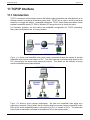
11 TCP/IP Interface ......................................................................................................................................................... 11-1
11.1 Introduction .......................................................................................................................................................... 11-1
11.2 TCP/IP Interface Setup Overview ........................................................................................................................ 11-2
11.2.1 TCP/IP InstantHMI Server Node................................................................................................................... 11-3
11.2.2 TCP/IP InstantHMI Client Node .................................................................................................................... 11-3
11.2.3 TCP/IP Client Objects in Screen Designer ................................................................................................... 11-3
11.2.4 TCP/IP Used in Project Deployment............................................................................................................. 11-5
11.2.5 TCP/IP Chat Utility........................................................................................................................................ 11-6
11.3 TCP/IP Interface Example ................................................................................................................................... 11-7
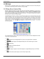
12 OPC Interface ............................................................................................................................................................. 12-1
12.1 Introduction .......................................................................................................................................................... 12-1
12.2 OPC Client Objects in Screen Designer .............................................................................................................. 12-2
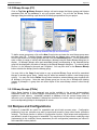
12.3 OPC over DCOM via TCP/IP ............................................................................................................................... 12-3
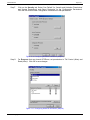
12.3.1 Configure DCOM on Server PC and Client PCs ........................................................................................... 12-3
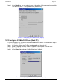
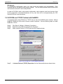
12.3.2 Configure DCOM for OPCEnum (Server PC) ............................................................................................... 12-7
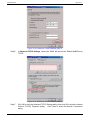
12.3.3 Configure DCOM for OPCEnum (Client PC)................................................................................................. 12-9
12.3.4 Domains vs. Workgroups.............................................................................................................................. 12-11
12.3.5 DCOM over TCP/IP Protocol with NetBIOS.................................................................................................. 12-12
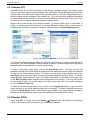
12.4 Example: DCOM for UniOPC Server ................................................................................................................... 12-14
12.4.1 Configure DCOM on Server PC.................................................................................................................... 12-14
12.4.2 Configure DCOM on Client PC ..................................................................................................................... 12-16
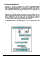
13 Historic Trend Utility.................................................................................................................................................... 13-1
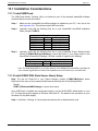
13.1 Installation Considerations................................................................................................................................... 13-2
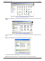
13.1.1 Install IHMITrend .......................................................................................................................................... 13-2
13.1.2 Install ODBC DSN (Data Source Name) Setup ............................................................................................ 13-2
13.1.3 Create Default IHMIDatalog-Default.MDB Database .................................................................................... 13-4
13.2 IHMITrend Program Elements ............................................................................................................................. 13-5
13.2.1 Status Bar ..................................................................................................................................................... 13-6
13.2.2 Main Menu .................................................................................................................................................... 13-7
13.2.3 File Menu ...................................................................................................................................................... 13-7
13.2.4 View Menu .................................................................................................................................................... 13-8
13.2.5 Window Menu ............................................................................................................................................... 13-8
13.2.6 Help Menu .................................................................................................................................................... 13-8
13.3 Application Data for Historic Trending ................................................................................................................. 13-9
13.3.1 Application Example ..................................................................................................................................... 13-9
13.3.2 Log Application Data..................................................................................................................................... 13-9
13.3.3 Analyze Logged Data in IHMITrend.............................................................................................................. 13-9
14 User DLL .................................................................................................................................................................... 14-1
14.1 Introduction .......................................................................................................................................................... 14-1
14.2 Writing User DLL ................................................................................................................................................. 14-1
14.3 Skeleton User DLL............................................................................................................................................... 14-2
14.4 Special Considerations ........................................................................................................................................ 14-4
14.5 Example 1: Read / Write PLC Data .................................................................................................................... 14-4
14.6 Example 2:Time Triggered Spooling.................................................................................................................... 14-6
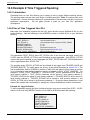
14.6.1 Introduction ................................................................................................................................................... 14-6
14.6.2 Use of Time Triggered User DLL .................................................................................................................. 14-6
14.7 Example 3:Time-Triggered Control...................................................................................................................... 14-7
14.7.1 Introduction ................................................................................................................................................... 14-7
14.7.2 Use of User DLL ........................................................................................................................................... 14-7
14.7.3 Application to Watlow Controllers ................................................................................................................. 14-9
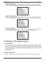
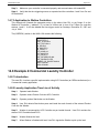
14.8 Example 4:Commercial Laundry Controller ......................................................................................................... 14-9
14.8.1 Introduction ................................................................................................................................................... 14-9
14.8.2 Laundry Application Time Line of Activity ..................................................................................................... 14-9
14.8.3 User DLL Overview....................................................................................................................................... 14-10
14.8.4 User DLL Project File Descriptions ............................................................................................................... 14-11
14.8.5 User DLL Classes......................................................................................................................................... 14-12
14.8.6 Remarks ....................................................................................................................................................... 14-12
A. Installation, Registration and Activation....................................................................................................................... A-1
A.1 Overview ............................................................................................................................................................... A-1
A.1.1 Compatible Hardware..................................................................................................................................... A-1
A.1.2 InstantHMI License Agreement ...................................................................................................................... A-2
A.1.3 Registration Activation Policy ......................................................................................................................... A-2
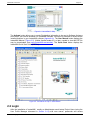
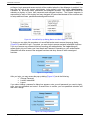
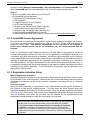
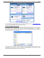
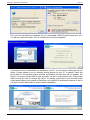
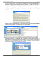
A.2 Installing InstantHMI.............................................................................................................................................. A-3
A.2.1 Installing LaunchPad Designer on PC............................................................................................................ A-3
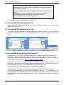
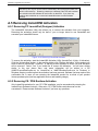
A.2.2 InstantHMI Runtime Engine for PC ................................................................................................................ A-8
A.2.3 InstantHMI Runtime Engine for CE ................................................................................................................ A-8
A.2.4 InstantHMI Runtime Engine for Pocket PC .................................................................................................... A-8
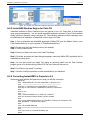
A.2.5 InstantHMI Runtime Engine for Palm OS ....................................................................................................... A-9
A.2.6 Converting InstantHMI 4.x Projects to 5.0 ...................................................................................................... A-9
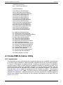
A.3 InstantHMI Activation Utility................................................................................................................................... A-10
A.3.1 Introduction..................................................................................................................................................... A-10
A.3.2 PC LaunchPad / Runtime Registration Activation .......................................................................................... A-11
A.3.3 PDA / CE Runtime Registration Activation ..................................................................................................... A-12
A.4 Moving InstantHMI Activation ................................................................................................................................ A-12
A.4.1 Moving PC Runtime Activation ....................................................................................................................... A-12
A.4.2 Moving PC LaunchPad (Designer) Activation................................................................................................. A-14
A.4.3 CE, PDA Runtime Installation......................................................................................................................... A-14
A.4.4 Backing up InstantHMI CE/PDA Activation .................................................................................................... A-15
A.5 Removing InstantHMI Activation ........................................................................................................................... A-16
A.5.1 Removing PC LaunchPad (Designer) Activation ............................................................................................ A-16
A.5.2 Removing CE / PDA Runtime Activation ........................................................................................................ A-16
B. FAQ - Frequently Asked Questions............................................................................................................................. B-1
B.1 What is 'InstantHMI Designed for OEM' ................................................................................................................ B-1
B.2 Assorted Questions ............................................................................................................................................... B-1
C. Communication Drivers............................................................................................................................................... C-1
InstantHMI for Your Application
Page 1-1
1 InstantHMI® for your Application
1.1 Introduction
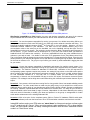
InstantHMI® incorporates our “Design Once, Deploy Anywhere” HMI technology. This will allow you
to design your HMI project on a Windows PC platform, and deploy it on any Windows PC, or
Windows CE, or PDA (Windows Mobile, Pocket PC or Palm) platform, which has an installed
InstantHMI Runtime engine. Install it on Windows PC platforms for a traditional single or multi-node
Client/Server HMI setup. For a mobile/wireless solution install it directly on a Windows Mobile PDA
or use our InstantChip™ technology to run from a CF/SD card. Use InstantPanel™, our Windows
CE color touch system (5.6", 8", 10.4" and 12.1" screens), for panel mount machine control
applications. Any InstantHMI runtime engine can stand-alone or be part of a client-server
network.
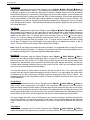
Figure 1.1: InstantHMI for Your Hardware Platform
InstantHMI 5.0 reinforces the 'Simpler is Better' Software Philosophy by re-architecting and reengineering the numerous HMI functions in InstantHMI 4.x. With its “Design Once, Deploy
Anywhere” HMI technology, the 'Simpler is Better' software philosophy, the many useful and
convenient features, and the ‘Instant On – Ready to Go’ approach of PDA based technology,
InstantHMI 5.0 hopes to be your preferred HMI/SCADA solution.
This manual covers all platforms on which InstantHMI can be deployed (Windows PC, Windows CE, Windows
Mobile, Pocket PC and Palm OS). All figures and discussions are illustrated with any one of the platforms
unless there are significant differences among the implementations for the different platforms in which case
the specific platform will be identified. Differences that are obvious or minor graphical appearance type will not
be documented. If a specific feature is critical for successful implementation of your project, you must verify its
availability; please contact Software Horizons for assistance.
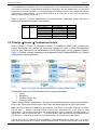
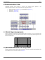
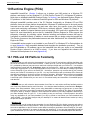
1.2 InstantHMI Design and Runtime Platforms
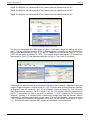
InstantHMI LaunchPad allows you to design your HMI project on a Windows PC platform, and
deploy it on any Windows PC, Windows CE or PDA (Windows Mobile, Pocket PC or Palm) platform,
which has an installed InstantHMI Runtime engine. PC-based HMI is well understood and most
people are familiar with the concept. However, since 'full featured HMI' on a PDA platform is not
commonly expected and is not well understood, in the rest of this section we address some salient
PDA and CE platform issues. While InstantHMI Nodes (Runtime engines) on various platforms can
interact with each other, any InstantHMI node (including a PDA node) can stand alone; that is,
PDA based InstantHMI does not require a PC node (to act as a 'server').
InstantHMI: Copyright © 2000-2008 Software Horizons Inc.
5.0 - 20Jul2008
InstantHMI for Your Application
Page 1-2
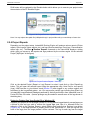
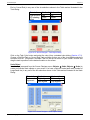
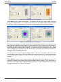
Figure 1.2: Illustrating InstantHMI on Windows CE and PDA platforms
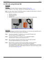
Why Deploy InstantHMI on a PDA? Mobility, low cost, and wireless connectivity are some of the reasons
why PDA based HMI can enhance your total HMI solution. We list a few illustrative scenarios below.
Scenario 1: You are the operator responsible for running your process. Your boilers are working OK but you
know you can make them work more efficiently if you could only monitor what the controller was doing. You
have that wonderful handheld computer (PalmTM or Pocket PC) in your shirt pocket. Moreover, you have
InstantHMI software installed in your handheld. You walk over to the controller cabinet, plug in the
communication cable to the serial port on the handheld, turn on the handheld, and tap the stylus over the
InstantHMI icon on the touch screen. The monitoring screen shows the Boiler Temperature and pressures for
the two boilers. (If your controller has an infrared port on it, you don’t even need a cable; just beam the
handheld’s built in IR head at the controller). Of course, InstantHMI will show any other variables that are
relevant to your task at hand. You decide to look at the P-I-D parameters for the Feed Water control loop.
Tap on the screen fields to change the tag names to display the P-I-D tags and the Set Points. Enter the new
values (based on your analysis) through the screen and switch to monitoring and log the data in the handheld
for the next ten minutes or so. Go get your cup of coffee (you earned it!), while InstantHMI is logging the data
for your review.
Scenario 2: You are the operator responsible for installation and startup of a machine control system. Your
task includes verifying that the Input/Output wiring for the system is as required before the machine can go
into production. The machine includes an elaborate PC based HMI. Verification of the I/O tags and the
corresponding system response requires two persons: one setting I/O tag values on the HMI screen and the
other to observe and verify the actual system component response. But you have a mobile, wireless Pocket
PC with InstantHMI installed on it. You walk over to a location where you can observe the system
component(s) of interest, use the InstantHMI I/O tags to set the I/O values, and observe the actual system
response. Your colleague can be doing other useful tasks during this verification period rather than act as your
helper.
Scenario 3: Your process, which has been running fine for a long period of time, has started exhibiting certain
unusual behavior. You have certain ideas on what may be going wrong, but you would like to collect some
additional data to confirm which of your thoughts are worth pursuing further in detail. Changes or additions to
the existing, elaborate, sophisticated HMI are not feasible over the short haul. You whip out your Pocket PC
based InstantHMI, collect some data for tags of interest, independent of and without disturbing the existing
HMI, and use this information to solidify your ideas and present it to the group or management for further
action and/or enhancement of the existing elaborate HMI.
Scenario 4: With a low price for the complete system (Palm or Pocket PC hardware, RS232 serial cable,
adapter and software) now even the lowest cost “micro” PLCs and other controllers can have their own HMI.
InstantHMI runtime engine on a PDA node can 'stand alone' as it does not require a runtime engine
on a PC node to act as a 'Server'. When a runtime engine is also available on a PC or other platform
nodes, the PDA based runtime can easily exchange information with the other InstantHMI runtime
nodes in a 'Client-Server' setup.
InstantHMI: Copyright © 2000-2008 Software Horizons Inc.
5.0 - 20Jul2008
InstantHMI for Your Application
Page 1-3
Quick deployment of InstantHMI on a PDA platform is possible (without the need for elaborate
Project setup) if you can take advantage of the integrated Runtime and Design screens of a
traditional HMI provided in InstantHMI by the use of a tag database (organized into tag groups) and
pre-formatted screens. The Scrollable Monitor screen allows the small touch screen of the handheld
to be used to view Data Registers, I/O bits, Timer/Counter values etc. in conveniently named tag
groups. (The Data Table function allows you to view / modify controller information even when you
have not setup any tags). Parameter values such as P-I-D can be input from the handheld by touch
or with the help of a stylus (Password protection is built-in). Register and other data values can be
logged in the handheld computer and reviewed later.
InstantHMI is Screens and Buttons oriented to make it straightforward and easy to use. PLC
communication protocol parameters can be easily configured. The Tag Editor allows you to add,
modify or delete tags. (OEM versions come with pre-created tag database). These tags are used to
monitor and /or modify data through the runtime screen. The Tag Group Manager allows you to
organize tags into named groups; this is useful in functional grouping of tags (Recipes, Configuration
etc.). InstantHMI allows on-demand data logging of selected tags in a database which can be
reviewed on the handheld in a scrollable table or the handheld can be connected to a desktop PC at
a later time to transfer the logged data for Historic Trending, Reporting or other analysis.
InstantHMI has an architecture which supports traditional HMI screens (designed and deployed
using the LaunchPad Development system) on PDA platforms. This feature permits OEM and
machine control applications to be built using specialized screens (see Project Protection, Section
2.4.3). If you have any special applications contact us so we may adapt InstantHMI to meet your
special needs.
InstantHMI runtime installed in the PDA (Palm OS or Pocket PC) makes configuration, diagnostic,
trouble shooting and data logging tasks for your controller equipment as simple as possible. The
compact shirt pocket size of the handheld and the infrared beaming and wireless RF capability
incorporated in InstantHMI, provide for the greatest mobility and make InstantHMI available ‘any
time, any place’ as a human machine interface. The creation of tags may be done directly on the
handheld with InstantHMI; however, this chore is made much more convenient using the
LaunchPad's Screen Designer (Section 4) running on a Windows Desktop PC.
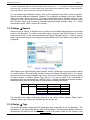
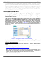
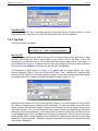
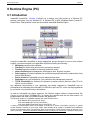
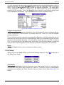
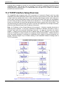
1.3 InstantHMI Overview
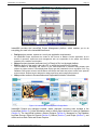
The important elements in the design and implementation of a Human Machine Interface (HMI) are
shown in the InstantHMI Architecture block diagram below.
InstantHMI: Copyright © 2000-2008 Software Horizons Inc.
5.0 - 20Jul2008
InstantHMI for Your Application
Page 1-4
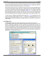
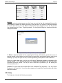
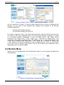
Figure 1.3: InstantHMI Architecture
InstantHMI provides the LaunchPad Project Management platform, which enables you to do
everything you need in the InstantHMI framework:
•
Design project screens, reports etc. to suit your application requirements.
An InstantHMI Project implements the 'model of the Process or Machine Control Application' for the
benefit of operators, supervisors and management who are responsible for the proper and efficient
operation of the machine and the plant.
•
•
Setup all project elements (and users) so it is 'Ready to Run' on the target platform.
RUN the project (if the target is the same PC on which the LaunchPad is installed).
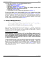
The information for Monitoring and Control of your machine/process is presented using display data
objects on project screens. These display data objects get their parameters from a tag object in the Tag
Database. Most project screens include Macros and Scripts that make the project screens more powerful
and convenient. Reports can be designed to assist supervisory and management personnel.
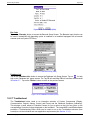
•
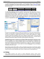
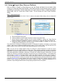
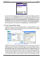
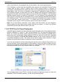
Help provides access to Documentation and Registration/Activation information.
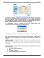
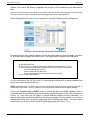
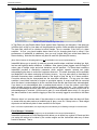
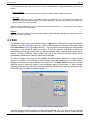
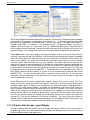
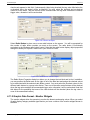
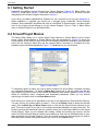
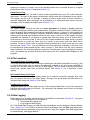
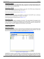
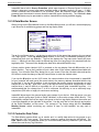
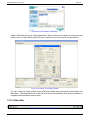
Figure 1.4: LaunchPad at Startup and in Design Mode
InstantHMI Projects are managed (created, stored, deployed, etc.)using tools included in the
LaunchPad (Section 2). Critical information used to define project elements is stored in Databases
(Section 3). The LaunchPad includes a Screen Designer (Section 4), Managers for Tag Database
and Data Sources, Editors for Reports (Section 5), Macros (Section 6), and Scripts (Section 7), and
utilities such as Data Table and Screen Capture.
InstantHMI: Copyright © 2000-2008 Software Horizons Inc.
5.0 - 20Jul2008
InstantHMI for Your Application
Page 1-5
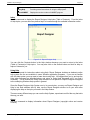
Your Project may include some or all of the Project Elements listed below:
• Tag Database (Section 2.3.4, Section 3.3),
• Screens (Section 2.3.1, Section 4),
• Report/Spool Templates (Section 2.3.3, Section 5),
• Data Sources (Section 2.3.5, Section 3.1), (controller and InstantHMI IP node address
database, communication setup parameters and drivers),
• Project Users (Section 2.4.2), and
• Target Platforms (PC, PDA, CE) where project will be deployed (Section 2.4.1).
The LaunchPad enables you to deploy InstantHMI Projects to one or more Runtime Engine
platforms of your choice: PC, PDA or Windows CE (Sections 9 and 10). The Runtime uses available
Communication Link(s) (Section 8) and its Communication Interfaces (Sections 11 and 12) to
retrieve Process/Machine information and renders them on the Operator Display for monitoring by
the Human Operator as well as enabling Operator input (using displayed screen objects and
keyboard, mouse or touch hardware) to control the Process/Machine operation. Runtime Engine
may also log Data for Historic Trending analysis (Section 13).
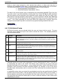
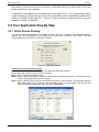
1.4 Get Started Immediately
•
•
•
•
Review InstantHMI License (see front of the manual)
Review Activation / Registration Policy, moving and removing the Activation (Appendix A)
Install InstantHMI LaunchPad on Windows PC and the Runtime Engine on target platforms
(Windows PC, CE, Pocket PC, Palm etc.). See Appendix A for details.
Register and Activate InstantHMI on all nodes (handhelds and Desktop)
Before proceeding further it is important that you take a minute to fill in and email, fax or mail your
Registration Form. This is the only way we have of informing you about important changes and
improvements to InstantHMI. Special update and support privileges are only available to Registered
customers, so please send in your registration form promptly.
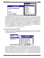
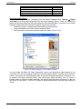
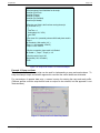
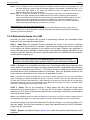
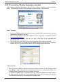
Quick Familiarity with InstantHMI
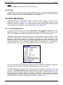
For illustrative purposes, InstantHMI includes a 18-Screen Demo Project, which includes a few
illustrative applications. To make it convenient for you, when you complete installing InstantHMI on
your PC, the LaunchPad (which serves as the command and control center from which you may
access the main program elements of InstantHMI) appears and presents you with an opportunity to
run the 2-minute demo. Run this 2-minute Demo to get a feel for various InstantHMI features that
you can use in your own application.
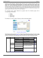
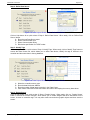
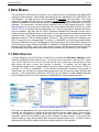
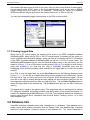
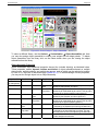
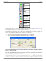
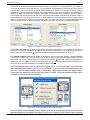
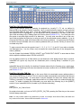
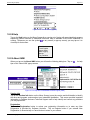
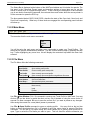
Throughout this manual we will use the Demo project for illustrative purposes. We recommend that
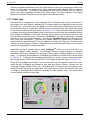
you use the Demo project elements (Screens, Scripts, Macros, etc.) as a tool to shorten your
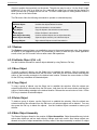
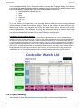
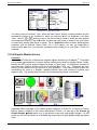
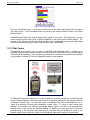
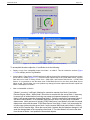
learning curve in using InstantHMI for your application solution. A sample screen from the
Temperature Monitoring application included in the Demo project (Figure 1.5) shows boiler and
pump states and allows the input of Temperature Setpoint and monitoring of (High/Low
Temperature) alarm conditions.
InstantHMI: Copyright © 2000-2008 Software Horizons Inc.
5.0 - 20Jul2008
InstantHMI for Your Application
Page 1-6
Figure 1.5: Demo Project-Sample Screen
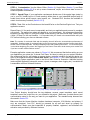
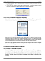
We recommend that for self-training on screen design, controller interface and project design you
refer to the separate document 'Quick Start Guide'. We include below a brief description of the
Water Supply System used in the Quick Start Guide for illustration. You may access the 'Quick Start
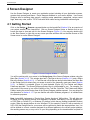
Guide' by clicking the Help button at the bottom left of the LaunchPad (Figure 1.4).
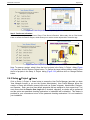
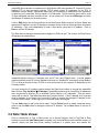
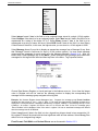
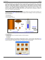
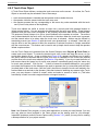
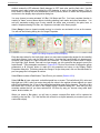
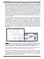
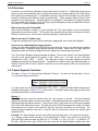
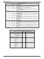
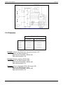
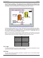
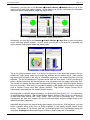
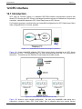
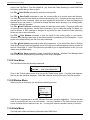
Figure 1.6: Application Example - Water Supply System
The Water Supply System for a small community consists of two Tanks A & B, a Well Pump, and a
Booster Pump station monitored and controlled from a central facility. Tank A supplies water to
community members living in its vicinity. Tank A draws its water from the Well by initiating a
'Required' command to the Well (Pump). Tank B supplies water to community members living in its
vicinity. Tank B draws its water from Tank A by initiating a 'Required' command to the Booster
Pump. Manual overrides are required at the central facility to operate Well Pump and Booster
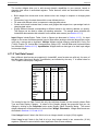
Pump. All Remote sites are connected to the host central site's PLC via radio RTUs. The variables
of interest (tabulated below) are maintained and the site logic is programmed in the PLC.
Our task is to provide a Human Machine Interface for the operator(s) in the Water Supply System
facility. InstantHMI can provide such an interface on multiple platforms. The HMI solutions on these
platforms are very similar.
InstantHMI: Copyright © 2000-2008 Software Horizons Inc.
5.0 - 20Jul2008
InstantHMI: LaunchPad
Page 2-1
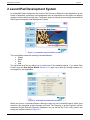
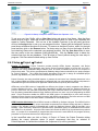
2 LaunchPad Development System
An InstantHMI Project implements the 'model of the Process or Machine Control Application' for the
benefit of operators, supervisors and management who are responsible for the proper and efficient
operation of the machine and the plant. The project design and setup are done using the LaunchPad
HMI-Project Development and Management System.
Figure 2.1: InstantHMI LaunchPad Before Activation
The LaunchPad includes the following Command Buttons:
• Design
• Setup
• Run
• Help
The pull-down list at the top allows you to select one of the available projects. If you select 'New
Project' here, the New Project Wizard (Section 2.4.1) pops up to guide you through creation of a
new project for your application.
Figure 2.2: InstantHMI LaunchPad After Activation
When you click on a Command Button a dialog box pops up in the LaunchPad panel, which gives
access to the associated project elements and tools. The hierarchy of project functions and the
associated Project Elements (Screens, Databases, etc.) as well as the Tool or Utility used in the
design and setup are shown in Figure 2.3.
InstantHMI: Copyright © 2000-2008 Software Horizons Inc.
5.0 - 20Jul2008
InstantHMI: LaunchPad
Page 2-2
Command
Functions
Project Elements
Tool or Utility
Design
Screens
Screen (Objects)
Scripts
Macros
Screen Designer
Script Editor
Macro Editor
Recipe Editor
Configuration Editor
Troubleshoot Editor
Report Designer
Report Designer
Alarm Viewer
Historic Trend Utility
Log Viewer
Tag Manager
Datalog Events Dialog
Message Manager
Bitmap Manager
Data Source Manager
IP Manager
New Project Dialog
Remove Project Dialog
Select Platform Dialog
User Profile Manager
Project Protection Utility
Deploy, Retrieve Dialog
Screen Designer,
Add, Insert, Remove, Delete Dialog
Report Designer, Assign, Remove,
Delete Dialog
Setup
Configurations
Troubleshoot Scripts
Reports
Printer Reports
Spool Reports
Alarm Reports
Historic Trends
Logs
Tags
Tag Database
Datalog Events
Message Groups
Bitmap Groups
Data Sources Comm Links
TCP/IP Links
Project
New Project
Remove Project
Change Platform
Users
Protect
Deploy
Screens
Project Screens
Reports
Run
Help
Printer Report
Templates
Spool Reports
Templates
Special Tags Print Control Tags
Spool Control Tags
Switch Screen Tags
Update Enable Tags
Recipe Enable Tags
Runtime Setup Project Runtime Setup
Emulate
Run
Runtime
Project Runtime
Reports
Reports
Activate
Designer
Runtime Engine
User Manual Documentation Manual
Quick Start
Quick Start Guide
See
Section
4
7
6
3.6
3.6
2.3.2
5
5
13
2.4.1
2.4.2
2.4.3
2.4.4
2.4.5
2.4.6
Tag Manager Add, Remove Dialog
2.4.7
Runtime Setup Dialog
Target Runtime Engine Emulation
PC Runtime Engine
Runtime Report Viewer
2.5.1
2.5.3
2.5.2
2.5.4
Activation Utility
2.1
Adobe Acrobat Viewer
Figure 2.3: Project Functions, Associated Project Elements and Design Tools
2.1 Help
The LaunchPad Help command displays program version information (Figure 2.4) and also provides
three buttons: Activate, User Manual, and Quick Start.
InstantHMI: Copyright © 2000-2008 Software Horizons Inc.
5.0 - 20Jul2008
InstantHMI: LaunchPad
Page 2-3
Figure 2.4: LaunchPad Æ Help
The Activate button allows you to create Registration information to be sent to Software Horizons
and receive your license activation for InstantHMI software. Activation is essential to access all the
installed features in your InstantHMI software (Appendix A). The User Manual button displays the
InstantHMI Manual ( Figure 2.5). (Adobe Acrobat reader 6.0, or later, needed to view this PDF file
may be downloaded from www.InstantHMI.com/acrobat). The Quick Start button displays the
InstantHMI Quick Start Guide (PDF file).
Figure 2.5: LaunchPad Æ Help Æ User Manual
2.2 Login
After the installation of InstantHMI usually an Administrator would setup Project Users (using the
User Profile Manager discussed in Section 2.4.2) with user names, passwords and access
InstantHMI: Copyright © 2000-2008 Software Horizons Inc.
5.0 - 20Jul2008
InstantHMI: LaunchPad
Page 2-4
privileges. Login password access control will be enabled when the User Manager is enabled. You
may play the role of the system administrator (using default Login User Name: Administrator,
Password: a ) and setup users, passwords and assigned functions. The InstantHMI LaunchPad
maintains a registry of users, their passwords and assigned functions. The System Integrator is
responsible for setup of this registry and may designate a System Administrator at the customer site
to setup additional users, passwords and assigned functions.
Figure 2.6: LaunchPad Pop-up Dialog (Before and After Login)
To Login you may right click anywhere on LaunchPad border area to access the pop-up dialog
(Figure 2.6) and select 'Login'. If required, you must Login to access assigned InstantHMI functions.
If you try to access any protected functions requiring user authentication, the Login dialog will
appear and to let you to enter your User Name and Password. Depending on your authentication
InstantHMI will allow access to the assigned functions and deny access to other unassigned
functions.
Figure 2.7: Login Dialog
After you login, you may access the pop-up dialog (Figure 2.6) to do the following:
• Change Password
• Lockout InstantHMI
• Logout
If you select 'change password' a dialog box appears: enter your old password (you used to login),
enter your new password and enter it a second time to confirm your new password selection and
then click Change.
Figure 2.8: Change Password
InstantHMI: Copyright © 2000-2008 Software Horizons Inc.
5.0 - 20Jul2008
InstantHMI: LaunchPad
Page 2-5
To Logout, select 'Logout <User Name>' and enter your password. The system will default to user
‘Guest' if no one is logged. The system administrator can decide what InstantHMI functions are
accessible when user is ‘Guest’.
To leave InstantHMI in a locked state, select ' Lock InstantHMI'. A Resume Screen appears and all
LaunchPad functions are locked out until you click on Resume button and enter your password.
Figure 2.9: Locking InstantHMI LaunchPad
2.3 Design
2.3.1 Design Æ Screens
InstantHMI implements a ‘Design Once Deploy Anywhere’ technology. The project Tag Database
can be transferred to any target platform, which has an installed InstantHMI runtime engine.
Likewise, the project screens created in the Screen Designer will be transferable to Windows PC,
CE and PDA platforms. Screens for different platforms with different screen resolutions may be
designed on the LaunchPad platform and converted (automatically) while deploying on the target
platform.
Figure 2.10: Design Æ Screens (Thumbnails View and List View)
The Design Æ Screens command shows all the screens included in the selected project (Demo, in
our example) as Thumbnail bitmaps or in a list. If you right click on any screen in the preview panel
you will see a popup menu of options: New Screen and Edit Screen. Double clicking on a screen in
the preview panel invokes the Screen Designer (Section 4) and allows the screen objects to be
viewed and edited. Note: Screen editing access may be restricted to designated users via Login
password control in the User Manager (Section 2.4.2).
InstantHMI: Copyright © 2000-2008 Software Horizons Inc.
5.0 - 20Jul2008
InstantHMI: LaunchPad
Page 2-6
The InstantHMI Screen Designer allows you to assign tags from the Tag Database to any data display objects
you include on the screen. If the desired tag definition is not already in the Tag Database then you may create
a tag on the fly using the Tag Editor, or if no tag specification is desired at the time then a default tag (linked to
local memory) will be generated. You may edit the default tag at a later time or use it as is for preliminary
testing of screen objects. (Section 2.3.4)
Table in Figure 2.11 briefly summarizes the screen elements, associated design tools and a
reference to Sections where these are discussed.
Command Function
Design
Screens
Screen Elements
Screen (Objects)
Scripts
Macros
Recipes
Configurations
Troubleshoot Scripts
Tool or Utility
Screen Designer
Script Editor
Macro Editor
Recipe Editor
Configuration Editor
Troubleshoot Editor
See Section
4
7
6
3.6
3.6
2.3.2
Figure 2.11: Designing Screen Elements
2.3.2 Design Æ Screen Æ Troubleshoot Scripts
Click on Design Æ Screen Æ Troubleshoot Scripts Æ Troubleshoot Editor button (provided your
System Administrator has granted you this access privilege) to create a custom troubleshooting
script for your application to be downloaded to the Runtime Engine on any supported platform.
Figure 2.12 shows a sample troubleshoot script database (IHMI-TroubleshootDB.idb) for a Watlow
Temperature Controller application.
Figure 2.12: Design Æ Troubleshoot Scripts and Troubleshoot Editor Dialog
Troubleshoot editor has four (hierarchical) levels for script customization:
• Topics,
• Symptoms,
• Possible Causes, and
• Corrective Steps.
'Topics' identify different subsystems or areas (in the application) that are prone to have problems.
Click on the 'Topics' entry field to enter a 'New Topic' (as shown) and click on 'Add Topic' button.
Note: 'Add Topic' button will be labeled as 'Add Symptom', 'Add Cause' or 'Add Step' depending on context.
Use the 'Add …', 'Remove', and 'Edit' buttons at the chosen hierarchical level of the script for script
customization. The text entry field is below the corresponding list (Topics, Symptoms, Possible Causes). To
add an entry, enter its text and click 'Add …'. To remove an entry, select the entry from the displayed list and
click 'Remove'. To edit an entry, select the entry and enter the new text and click on 'Edit' button.
The text entry field for Corrective Steps is scrollable to allow detailed multi-line entries. Also, one or more
action steps may be required to correct a selected Possible Cause. To add a 'Corrective Step', enter its text in
InstantHMI: Copyright © 2000-2008 Software Horizons Inc.
5.0 - 20Jul2008
InstantHMI: LaunchPad
Page 2-7
Corrective Steps text field and click 'Add Step' button. Use the |<, <, >, >| buttons to select any specific
corrective step. To remove a corrective action step, select it and click the Remove button. To edit a corrective
action step select it, enter the new text, and click the 'Edit' button.
For any selected topic (Example: Alarms), click on the 'Symptoms' entry field to enter a symptom.
Repeat entering additional symptoms if desired. Two symptoms are shown for the topic 'Alarms':
Alarm won't clear, Alarm won't occur. For each Symptom add a list of 'Possible Causes' for the
symptom that the user can identify (example: Alarm set points incorrect) and then proceed to enter
the 'Corrective Steps' script to assist in troubleshooting the problem (example: Step 1 of 1: Check
the operation mode). Finally, click on 'Done' button.
2.3.3 Design Æ Reports
When you click on Design Æ Reports button, you will see the Available Report types for the selected
project in the left panel. To create a new printer report, select its type (Printer Report) in the left
panel and then click on the associated design tool (Report Designer) button. To edit an existing
printer report, select its type in the left panel and then double-click on the specific report name in the
right panel.
Figure 2.13: Design Æ Reports
Other Report types (Spool Reports, Alarm Reports, Historic Trends and Logs) are created or edited
in a similar manner. The LaunchPad provides access to the Report Designer (Section 5) to create
the spool and printer report templates that can be used by the runtime engines to produce printer
and spool reports. In addition Special Tags (Section 2.4.7) can be setup in the LaunchPad to
generate event driven reports and logs. Table in Figure 2.14 briefly summarizes the report elements,
associated design tools and a reference to Sections where these are discussed.
Command Function
Design
Reports
Report Elements
Printer Reports
Spool Reports
Alarm Reports
Historic Trends
Logs
Tool or Utility
Report Designer
Report Designer
Alarm Viewer
Historic Trend Utility
Log Viewer
See Section
5
5
13
Figure 2.14: Designing Report Elements
The LaunchPad can collect all Reports produced in the various runtime engines: Printer, Spool,
Datalogs, Alarm Logs, Event Logs, System/User activity logs, etc.
2.3.4 Design Æ Tags
The screen data display objects get their parameters from a tag object in the Tag Database. The
data source for the tag provides the raw data of the tag object. The screen data display object then
translates the raw data into the chosen display format of the screen object for your viewing on the
InstantHMI: Copyright © 2000-2008 Software Horizons Inc.
5.0 - 20Jul2008
InstantHMI: LaunchPad
Page 2-8
screen. Clicking on Design Æ Tags and selecting the Project Element 'Tag Database' displays the
tags defined in the tag database (Figure 2.15).
Figure 2.15: Design Æ Tags Æ Tag Database
Table in Figure 2.16 briefly summarizes the tag elements, associated design tools and a reference
to Sections where these are discussed.
Command Function Tag Elements
Design
Tags
Tag Database
Datalog Events
Message Groups
Bitmap Groups
Tool or Utility
Tag Manager
Datalog Events Dialog
Message Manager
Bitmap Manager
See Section
3.3
3.7
3.4
3.5
Figure 2.16: Designing Tag Elements
The tags in the InstantHMI Tag Database have separate raw data and display format parameters.
Depending on the raw data source, each tag can have an IP address assigned to it in the Data
Source Æ IP Manager. The IP Manager maintains a list of IP addresses, port numbers, and
descriptive names for the devices (controller and InstantHMI runtime nodes). The Data Source
entries include a driver name so that InstantHMI can support multiple brands of controllers over the
same TCP/IP network simultaneously.
Figure 2.17: Design Æ Tags Æ Tag Database Æ Tag Manager
The InstantHMI Screen Designer allows you to assign tags from the Tag Database to any data display objects
you include on the screen. If the desired tag definition is not already in the Tag Database then you may create
a new tag on the fly using the Tag Editor, or if no tag specification is desired at the time then a default tag
(linked to local memory) will be generated. You may edit the default tag at a later time or use it as is for
preliminary testing of screen objects.
InstantHMI: Copyright © 2000-2008 Software Horizons Inc.
5.0 - 20Jul2008
InstantHMI: LaunchPad
Page 2-9
Figure 2.18: Tag Editor
The Tag Manager (implemented as a DLL) serves as a common interface for use with the Screen
Designer, Runtime Engine, Report Designer, and other LaunchPad utilities. The Data Table
implementation in InstantHMI allows for rapid creation of pre-tested tags, which can be transferred
to the Tag Database. The Tag Manager allows for automatic tag name creation and tag
customization where prefix and postfix strings can be included in tag names. The prefix and postfix
may be variable based on the memory type, data type, and other such parameters. The tag names
can be edited to suit your preference at a later time.
2.3.5 Design Æ Data Sources
InstantHMI implements a Data Source Manager (as a DLL) that maintains a list of all the data
sources. The data source identifies where the runtime data will come from. Typically, field sensor
devices bring the physical plant/machine data to the I/O modules on the controller. As far as
InstantHMI is concerned the raw data is stored in the controller memory. The controller (stations)
may be in a network. The communication link between the InstantHMI node and the raw data may
be any of the following:
• direct serial link,
• infrared link,
• TCP/IP link to controller,
• TCP/IP link to a remote InstantHMI node, to which the data source is linked,
• Barcode Scanner, and
• OPC Server (to which the data source is linked).
Figure 2.19: LaunchPad Æ Design Æ Data Sources
InstantHMI: Copyright © 2000-2008 Software Horizons Inc.
5.0 - 20Jul2008
InstantHMI: LaunchPad
Page 2-10
To request and receive data from the controller, a Communication Protocol must be followed; this
protocol is incorporated in the communication driver in InstantHMI. Table in Figure 2.20 briefly
summarizes the Data Source elements, associated design tools and a reference to Sections where
these are discussed.
Command Function
Data Source Elements Tool or Utility
See Section
Design
Data Sources Comm Links
Data Source Manager 2.3.5
2.3.5
TCP/IP Links
IP Manager
Figure 2.20: Designing Data Source Elements
The Data Source Manager maintains a database of data sources. Each data source will have a
name (you provide) to identify it. In addition, you will select the communication driver and the
communication link (Direct Serial, Infrared, TCP/IP to controller, or TCP/IP to InstantHMI). If the
selected communication method is direct serial or infrared then you will setup the communication
parameters such as baud rate, parity, data bits, and stop bits. If the communication method is
TCP/IP then you will select or create a Device Name that links to the IP address and Port # of the
controller or InstantHMI device that originates the data.
Figure 2.21: Data Source Manager and Editor
Each tag in the tag database will have a Data Source attached to it. For the active objects placed on
a screen, you will be able to override the tag data source at screen creation time if you so desire.
This may be necessary for projects where you want to view the same parameter on multiple
controllers, where the only difference may be the IP address or station number. In the case of the
station number you may use the station offset concept at the active object level. If a station offset is
specified this offset will be added to the station number specified in the tag object.
InstantHMI allows access to controllers over an Ethernet LAN using wireless RF connectivity (using
EtherNet/IP, Modbus TCP or other protocols involving TCP/IP which require IP addresses for the
PLC or InstantHMI runtime nodes). InstantHMI makes the job of specifying IP addresses more
convenient by allowing you to associate ‘Device Names’ to IP addresses. Only the device names
will be used in Tags associated with that controller device so that if a network is reconfigured,
updating the tag database is easy. All you need to do is use the IP Manager to reenter the changed
IP address for the device name.
When assigning a target platform (PDAs, or PCs, or CE panels) to the project you will be able to specify
whether the data source for each tag is Local or Remote. When the data source is Local, it will be polled by
the runtime engine on the target platform; and when the data source is Remote, the tag data (for this client
node) will come from another InstantHMI runtime engine on a platform (server node) identified by you.
2.4 Setup
Project Setup command gives access to Project Management features. These include
administrative functions (such as setting up Project Users and their access privileges, Deploying
InstantHMI: Copyright © 2000-2008 Software Horizons Inc.
5.0 - 20Jul2008
InstantHMI: LaunchPad
Page 2-11
Projects on target platforms), assigning project elements (such as operator Screens, Printer and
Spool Reports), and setting up Special Registers for creating event-driven Printer reports, Spool
reports, etc. Without Administrative privileges you will not be able to access the Project Users
button and some other critical setup features. For each selected function, the Project Setup dialog
reconfigures itself to display the details in panels and provides appropriately labeled function buttons
to let you accomplish the desired project management objectives. All setup functions apply to the
specific project selected from the pull down list of projects.
For convenient setup, project elements are grouped under four functional groups with a
correspondingly labeled button:
•
•
•
•
Project,
Screens,
Reports, and
Special Tags.
For example, if you click on Setup Æ Project you will see the following dialog.
Figure 2.22: Setup Æ Project
The hierarchy of setup functions and the associated Project Elements as well as the Tool or Utility
used in the setup are shown in Figure 2.23. Click on one of these function buttons, select a project
element on the left and/or right hand panel and proceed with your setup of that project element.
Command Functions
Setup
Project
Screens
Project Elements
New Project
Remove Project
Change Platform
Users
Protect
Transfer
Project Screens
Reports
Printer Report Templates
Tool or Utility
New Project Wizard
Remove Project Dialog
Select Platform Dialog
User Profile Manager
Project Protection Utility
Deploy, Retrieve Dialog
Screen Designer,
Add, Insert, Remove, Delete Dialog
Report Designer,
Assign, Remove, Delete Dialog
Section
2.4.1
2.4.2
2.4.3
2.4.4
2.4.5
2.4.6
Spool Reports Templates
Special Tags Print Control Tags
Spool Control Tags
Switch Screen Tags
Update Enable Tags
Recipe Enable Tags
Tag Manager Add, Remove Dialog
2.4.7
Figure 2.23: Setup Functions, Associated Project Elements and Design Tools
InstantHMI: Copyright © 2000-2008 Software Horizons Inc.
5.0 - 20Jul2008
InstantHMI: LaunchPad
Page 2-12
2.4.1 Setup Æ Project (New, Remove, Platform)
Click on Setup Æ Project Æ New Project (or use the Project pull-down list and select <New
Project>) to access the New Project Wizard. The wizard will guide you through the steps in creating
and testing a new project. Click on Help button for a quick review of 'Step 1: Create New Project'.
When ready, click on 'Create New Project' button. This will display the 'New Project Definition'
dialog.
Step 1: Create New Project
Click on Help button for a quick review of how to create a new project. When ready, click on 'Create New
Project' button.
Figure 2.24: New Project Wizard - Step1: Create New Project
A. Enter the desired project name
B. Choose <Default> or other Project Template to create a new project folder
C. Accept Runtime Platform inherited from the project template or change the Target Runtime
Platform (Windows PC/CE/Mobile, Pocket PC, Smart Phone or Palm OS) using the pull-down list.
D. Accept the Screen Resolution inherited from the project template or change it to one of the
available Screen Resolutions for your new project.
This will allow you to design your HMI project screens on a Windows PC platform, and deploy it on the target
platform, which has an installed InstantHMI Runtime engine. Click on Done button to proceed with the new
project creation or 'X' to cancel. The New Project Wizard will take you to the next step.
Note: You may use the 'Change Platform' button to change the 'Screen Resolution' to match the screen
size/resolution for a new target platform at a later date. This would be 640x480 (or higher) for desktop
applications, 240x320 (or higher) for Pocket PC/ Windows CE based applications, and 160x160 (or higher) for
Palm based applications. InstantHMI implements a “Design Once, Deploy Anywhere” HMI solution; you may
design your screens for one platform and easily convert them for use on another platform. To accomplish this,
click on Setup Æ Project Æ Change Platform, switch the platform selection, and then click on Setup Æ
Screens button (Section 2.4.5) and then re-save each of the project screens for the new platform (resolution).
You may use the automatic re-saving (of screens and other selected project elements) feature built-in project
protection (Section2.4.3) to change platform and screen resolution. Simply select a simple password to protect
screens, let the screens be 'protected' and re-saved. Repeat the same, resetting the password to 'no
password'. Project Designer/Administrator usually deploys projects and not the operator.
InstantHMI: Copyright © 2000-2008 Software Horizons Inc.
5.0 - 20Jul2008
InstantHMI: LaunchPad
Page 2-13
Step 2: Define Data Source
Figure 2.25: New Project Wizard - Step2: Define Data Source
Click on Help button for a quick review of 'Step 2: Define Data Source'. When ready, click on 'Define Data
Source' button.
A. Enter the new Data Source name
B. Select Communication Link
C. Select Communication Driver
D. Edit device specification for TCP/IP nodes
Step 3: Identify Tags
Click on Help button for a quick review of 'Step 3: Identify Tags'. When ready, click on 'Identify Tags' button to
access the Data Viewer tool, which allows you to define data blocks, identify the tags of interest in the
controller and then save them to the tag database.
Figure 2.26: New Project Wizard - Step3: Define Data Source
A.
B.
C.
D.
Select the controller memory type
Enter the data block start address
Enter the number of data items to monitor in the Data Viewer
Click 'Online' button and let the Data Viewer tool retrieve and display the memory data values
Step 4: Design Screen
Click on Help button for a quick review of 'Step 4: Design Screen'. When ready, click on ' Design Screen'
button to access the Screen Designer, which allows you to create widgets and other data blocks on the
screen, tie them to controller tags. You may also create text and other graphic objects and then save the
screen.
InstantHMI: Copyright © 2000-2008 Software Horizons Inc.
5.0 - 20Jul2008
InstantHMI: LaunchPad
Page 2-14
Figure 2.27: New Project Wizard - Step4: Design Screen
Step 5: Test Screen in Runtime
Click on Help button for a quick review of 'Step 5: Test Screen in Runtime'. When ready, click on 'Run Screen'
button to access the Runtime Engine, which allows you to test the screen objects tied to controller tags.
Figure 2.28: New Project Wizard - Step5: Test in Runtime
Note: To remove a project, select it from the list of projects in the Setup Æ Project dialog (Figure
2.22) and then click on Remove Project button. To change the target runtime platform select it from
the list of projects in the Setup Æ Project dialog (Figure 2.22) and then click on Change Platform
button.
2.4.2 Setup Æ Project Æ Users
Click on Setup Æ Project Æ Users button to access the User Profile Manager (provided you have
'User Manager Access' or you are the System Administrator). User Profile Manager allows the
creation of users with different access levels such as System Integrator, Administrator, Designer,
and Operator. Each user level has default properties that are assigned to that access level. You
must ensure that the Require User Login box is checked, otherwise, no checks will be performed
and the entire user password checking mechanism in InstantHMI will be disabled. This feature is
provided for your convenience to turn off the password checking mechanism if it is not needed in
your installation.
InstantHMI: Copyright © 2000-2008 Software Horizons Inc.
5.0 - 20Jul2008
InstantHMI: LaunchPad
Page 2-15
Figure 2.29: Setup Æ Project Æ Users Æ New User 'Operator - Joe'
To set up a new User Profile, click on New User button and enter a User Name. Note that User
Name must be unique. Select the Access Level from the pull-down list, enter a User Password and
repeat to Confirm Password. Click on one of the Available Functions (in the left panel) and then
click on the Assign button to set up a user assigned function. Repeat until the Assigned Functions
panel shows all desired functions for this user. To remove an Assigned Function, select it in the right
panel and then click on the Remove button. For faster setup you may click on the Assign All button
and selectively Remove the undesired user assigned functions. Click the Save User button to save
the user profile in the user database (IHMI-UsersDB.idb). Click the Delete button to delete the
selected user from the user database. Click 'X' button to Cancel (without saving) the user setup in
progress. Click Done when finished setting up User Profiles.
2.4.3 Setup Æ Project Æ Protect
Benefits of Protection: Project Protection provides benefits OEMs, System Integrators, and Project
Designers. InstantHMI project designers may use the Project Protection feature to prevent the end users /
operators from using InstantHMI design features (such as screen modifications) that are not required to
perform their tasks. This will be accomplished by disabling design features selected by the project designer
for 'Project Protection'. Thus, OEMs and System Integrators will be able to design an InstantHMI project
(screens, tag database, etc.) that can not be modified by their end users.
Project Protection has many beneficial aspects. It protects the end users from 'shooting themselves in the
foot'. It allows OEMs and System Integrators to safeguard their own value-add project design components in
InstantHMI and gain future business for application enhancements required by their customers.
OEMs may sell an OEM version of InstantHMI at a different price (higher or lower) compared to the Software
Horizons published list price. If the OEM sells InstantHMI at a higher price than the Software Horizons list
price (to reflect their own value-add components) the Project Protection feature will prevent their end users
from purchasing InstantHMI software through Software Horizons at a lower cost, thus safeguarding the OEM
sales. Project Protection enables the OEM to sell OEM version of InstantHMI at a price lower than the
Software Horizons list price (as a 'bundling promotion' with OEM's own products). End users who are not OEM
customers will be unable to use OEM version of InstantHMI for non-OEM projects.
OEM Protection Mechanism: Each OEM is issued an OEM ID by Software Horizons. This OEM ID will be
stored with the project to identify unique value added components from different OEMs, and also by Software
Horizons. The standard version of InstantHMI will contain the Software Horizons OEM ID internally in the
software. When necessary, OEMs will be provided with a specialized version of InstantHMI that will contain
their OEM ID in the software. All project files created will contain the OEM ID of the software that produced
them. If a project file is accessed by a program that does not have the same OEM ID, the program will deny
permission to run and not allow access to that project file.
In the LaunchPad when you click on Setup Æ Project Æ Protect, the Project Protection dialog
displays the current protection status of project components that may be selected to
Protect/Unprotect. A checked box indicates the component is (or will be) protected.
InstantHMI: Copyright © 2000-2008 Software Horizons Inc.
5.0 - 20Jul2008
InstantHMI: LaunchPad
Page 2-16
Figure 2.30: Setup Æ Project Æ Protect
An unchecked box indicates the component is (or will be) unprotected. After selecting the desired
components, enter a password and click on Change Protection. (Click 'X' to cancel, that is, leave the
dialog without making any changes to component protection.) You should record this password in a
safe place for any future changes to the project protection. This password will be used in all future
protection schemes for this project until the project is completely unprotected.
If you have selected 'Screens' to be protected you will see the dialog box shown below.
Subsequently, each screen being protected will be displayed briefly.
Figure 2.31: Screen Protection
To change the password for a protected project, you must login with the old password and unprotect
it, select components to protect, enter the new password, and then protect the project again.
Note: You may use the automatic re-saving (of screens and other selected project elements) feature built-in
project protection to change platform and screen resolution. Simply select a simple password to protect
screens, let the screens be 'protected' and re-saved. Repeat the same resetting the password (to no
password).
Forgotten Password?: If the designer (OEM or End User) should forget his project protection password, the
OEM or Software Horizons (as appropriate) may be able to provide, a temporary unlocking password that will
be good for the day that it is issued. It is preferable for the designer to maintain both a protected and
unprotected version of their project to avoid the need for requesting a temporary password and any applicable
service charge.
Protection Verification: Among other things, an InstantHMI project includes a mandatory master protection
file. A protection file must be present to run your project (whether protected or unprotected). This file includes
information about the following items:
•
•
•
•
•
Version of the software used for protection
OEM ID
Time and date of protection
Status of project components (protected/unprotected)
Password to protect/unprotect the project components
InstantHMI: Copyright © 2000-2008 Software Horizons Inc.
5.0 - 20Jul2008
InstantHMI: LaunchPad
Page 2-17
It is strictly recommended that no attempt be made to tamper with or modify this protection file. A corrupted
protection file will render your InstantHMI installation useless as it will not be able to run any of your projects.
When running the protected project, the runtime will verify that all project components conform to the
original 'protected file' state by checking the information stored in the master protection file with the
information in the component files. If any project component fails the verification, the project will not
be run and will produce an error code and a log file.
2.4.4 Setup Æ Project Æ Deploy
InstantHMI LaunchPad allows you to design your project on a Windows PC platform, and deploy it
on any target platform such as Windows PC, or Windows CE, or PDA (Palm or Pocket PC), which
has an installed InstantHMI Runtime engine. We assume you have established connectivity between
the design PC and the runtime platform (see details below for various platform connectivity) before
attempting to deploy the project.
If the Project you wish to deploy is different from the current project, select it from the pull-down list
of projects. Click on the Setup Æ Project Æ Deploy button in LaunchPad. Select the Runtime
Platform to Deploy to, and the Transfer Action (Deploy or Retrieve). In the 'Select Project Elements'
list box select the items (such as Tag Database, Project Screens, etc.) you want to deploy to the
runtime platform (Pocket PC platform illustrated in Figure 2.32). Click on 'Start in Screen Mode' on
the target node if desired. Finally, click on Deploy button to transfer the selected project elements to
the target node.
Figure 2.32: Setup Æ Project Æ Transfer Æ Deploy to Pocket PC
Note that this feature allows you to Deploy a single master project on the Desktop PC to several
target nodes.
Connectivity with Pocket PC Platform
InstantHMI uses the database synchronization feature 'Active Sync' on Pocket PC platforms to deploy
projects.
Step 1. If Active Sync is not installed on your PC, do so now. ActiveSync can be downloaded from the
Microsoft Website using the following link:
http://www.microsoft.com/windowsmobile/downloads/activesync38.mspx
Step 2. If ActiveSync software is running you will see the Active Sync icon in the Windows System Tray (on
the bottom right of the Windows task bar which includes the Windows Start button). If not, click Start Æ
Programs Æ Microsoft ActiveSync to start Active Sync, then click File Æ Get Connected.
Step 3. Connect the Pocket PC to your PC.
InstantHMI: Copyright © 2000-2008 Software Horizons Inc.
5.0 - 20Jul2008
InstantHMI: LaunchPad
Page 2-18
Connectivity with InstantPanel (Windows CE Panel) Platform
InstantHMI uses the database synchronization feature 'Active Sync' on Windows CE platforms to deploy
projects. To Serially ActiveSync with a Windows CE Panel provided by Software Horizons, use the following
instructions.
Step 1. If Active Sync is not installed on your PC, do so now. ActiveSync can be downloaded from the
Microsoft Website using the following link:
http://www.microsoft.com/windowsmobile/downloads/activesync38.mspx
Step 2. Run ActiveSync on your PC, then click File Æ Get Connected.
Step 3. Connect COM1 (DB9 Male) on CE Panel to RS-232 on PC using adapter provided by Software
Horizons.
Step 4. On PC, click Next button in ActiveSync.
Step 5. On CE Panel, Navigate to the Windows folder (My Computer -> Windows) and run REPLLOG.EXE.
Step 6. On PC – once connected, you will be prompted to create a Partnership. We recommend that you
do this (as this is necessary to use Network ActiveSync later on).
Connectivity with Palm OS Platform
InstantHMI uses the database synchronization feature 'Hot Sync' on Palm OS platforms to deploy projects.
Step 1. If Hot Sync is not installed on your PC, do so now. HotSync software is usually supplied with your
Palm PDA.
Step 2. If the HotSync Manager software is running you will see the HotSync icon in the Windows System
Tray (on the bottom right of the Windows task bar which includes the Windows Start button). If not, click
Start Æ Programs Æ Palm Desktop Æ HotSync Manager to start the HotSync Manager.
Step 3. Connect the HotSync cradle to your PC.
InstantHMI LaunchPad software running on the Desktop Windows PC does not require the Palm Desktop
software to be running to perform its Deploy Project functions. Moreover, if you click the 'Setup Æ Project Æ
Transfer Æ Deploy' button in LaunchPad, InstantHMI LaunchPad will offer to start the HotSync Manager
automatically. You will see a list of Palm Users to Sync with. Click on Add User(s) button and select users
from the list of available Palm Users and click OK. You may also Remove Users form the list by first selecting
the user in the list and then clicking on the Remove User(s) button.
Using TCP/IP to Transfer InstantHMI Project(s)
This feature is not available at this time.
2.4.5 Setup Æ Screens
When you click on the Screens button, you will see the Available Screens for the selected project in
the left panel (see Figure 2.33). Use the buttons provided (Add, Insert, and Remove) to define which
screens from the Available List of screens are included in your project. In our example, the Demo
project is selected and 18 screens are included in the list of Project Screens. To exclude the
'PalmTempMonitor.scr' screen from the Demo project, click to highlight and select it in the ‘Project
Screens’ panel and then click on the Remove button. To create a new screen for the project, click
on the New Screen button or click on the Screen Designer button.
InstantHMI: Copyright © 2000-2008 Software Horizons Inc.
5.0 - 20Jul2008
InstantHMI: LaunchPad
Page 2-19
Figure 2.33: Setup Æ Screens
2.4.6 Setup Æ Reports
When you click on the Reports button, you will see the Available Reports (Printer or Spool,
depending on the radio button selection) for the selected project. Use the Assign button to define
which printer report (templates) is assigned to a specific printer report slot number in your project.
For example, click on 'Service Log.prt' report template on the left hand panel to select it, click on slot
3 on the right panel, and then click on Assign button to make the assignment as shown (Figure
2.34).
Figure 2.34: Setup Æ Reports Æ Printer
To exclude a previously assigned printer report from the project, click to highlight and select the
printer report in the ‘Assigned Printer Reports’ panel and then click on the Remove button. To
create a new printer report template for the project, click on the Report Designer button. Our
discussion here for 'Printer Reports' applies to Spool Reports as well.
The slot number are used at Runtime to associate reports with screens. The spool and printer report
templates are used by the runtime engines to produce printer and spool reports. In addition, Special
Tags can be setup in the LaunchPad to generate event driven reports and logs. The LaunchPad can
collect all Reports produced in the various runtime engines: Printer, Spool, Datalogs, Alarm Logs,
Event Logs, System/User activity logs, etc. for later analysis.
2.4.7 Setup Æ Special Tags
When you click on the Special Tags button, you will see the Tags assigned to serve special tag
functions (Section 9.3.3):
InstantHMI: Copyright © 2000-2008 Software Horizons Inc.
5.0 - 20Jul2008
InstantHMI: LaunchPad
•
•
•
•
•
Page 2-20
Print Control,
Spool Control,
Switch Screen,
Update Enable, and
Recipe Enable.
Figure 2.35: Setup Æ Special Tags (Print Control)
For example, the tag named 'Demo-Print Register' is assigned the Print Control special tag function.
To define a special tag, click on the Special Tag function on the left hand panel (Print Control
selected in Figure 2.35) and then click on 'Assign' button. This will invoke the Tag Manager to select
or define associated tag(s) from the project tag database to be used to trigger printer reports
included in your project. To exclude a tag from the Assigned Tags list click to highlight and select it,
and then click on the De-Assign Tag button. To create a new tag (to be assigned for Print Control),
click on the Tag Manager button.
2.5 Run
When you click on the Run command button, the LaunchPad displays the Splash screen for the
selected project with a count down (of 10 seconds). You may now click on the Pause button to
suspend auto-run of the project. At this time, you may verify Project Overview and Options before
clicking on Run button to start execution of the project in the Runtime Engine. After project
execution, the 'Runtime Reports' may be viewed as well. Without Runtime execution privileges you
will not be able to access the Runtime Engine.
Figure 2.36: LaunchPad Æ Run Command - Count Down
Note: If the target platform is not a PC, you may 'Emulate' it using runtime engine on PC (if available). You
may replace the image file (IHMIProjectImage.bmp) in your project folder with your own project image bitmap
of same size. Likewise, IHMICompanyImage.bmp may also be replaced.
InstantHMI: Copyright © 2000-2008 Software Horizons Inc.
5.0 - 20Jul2008
InstantHMI: LaunchPad
Page 2-21
2.5.1 Project Overview
Figure 2.37: Project Runtime Overview
Click on the Overview button to pop-up the Project Overview dialog, which shows project elements
included in your project: the number of screens in your project, the platform on which the project will
be deployed, etc.
Note: You may right click on the LaunchPad and select 'Project Overview' from the pop-up menu, to display
the Project Overview dialog.
2.5.2 Project Runtime Options
Figure 2.38: Project Runtime Options
Click on the Options button to pop-up the Project Runtime Options dialog, which shows project
runtime parameters for your project. Double click on any of them to review and/or change its value.
Note: These parameters are saved in the file Project.ini in your project folder and may be edited using
Windows Notepad.
2.5.3 Run/Emulate Project
When you click on the Run button, the LaunchPad displays the Splash screen for the selected
Project. The Run Function button is enabled if the Target Platform for the current project is the
Windows PC platform (on which the LaunchPad is installed). Otherwise, the RUN button will be
replaced with the 'Emulate Target' button. If you are ready to run the project, click on the Run
(Project) button. If your project runtime target platform is PC (and you have the Runtime Engine
installed on the same PC as LaunchPad) your project will start executing under the control of the
Runtime Engine. If your project runtime target platform is not the same PC as the LaunchPad, the
InstantHMI: Copyright © 2000-2008 Software Horizons Inc.
5.0 - 20Jul2008
InstantHMI: LaunchPad
Page 2-22
RUN button will be replaced by the Emulate button which allows you to execute your project under
the emulation of the PC Runtime Engine.
Figure 2.39: Project Execution - Splash Screen
Note: You may replace the splash file (IHMIsplash.bmp) in project folder with your own bitmap of same size.
2.5.4 Project Reports
Depending on the project setup, InstantHMI Runtime Engine will produce various reports (Printer
reports, Spool reports, Alarm reports, etc.) and logs (Runtime data logs, Event logs, Communication
status logs, etc.). The Run Æ Runtime Reports command on the LaunchPad displays a dialog
which gives you access to the reports and logs produced by the runtime engine for the selected
Project ('MyProject' in the figure).
Figure 2.40: Project Runtime Reports - View Log
Click on the desired Project (Report or Log) Element to select it and click on View Report/Log
button. This will open the selected report using the appropriate utility: Note Pad for text reports
(logs), IHMITrend.exe to view historic trend (Section 13) data logged in any runtime engine and
transferred to the LaunchPad system., etc. You may access various logs including User Event Log
in InstantHMI LaunchPad and Datalogs transferred by ActiveSync/HotSync from InstantHMI runs on
Pocket PC/Palm OS nodes. (Access privilege may be needed to access some of the logs shown in
the dialog box.)
Retrieving 'Datalog Data' from Pocket PC or Windows CE
Suppose your project run on the target (Pocket PC or CE) platform logged data for several tags over
a period of time and you wish to retrieve the logged data (and view it in Microsoft Excel, for
example). Click on the Runtime Reports, select Datalog Data and click on Retrieve Logs button
(Figure 2.40). If the target platform is properly linked to the LaunchPad PC, then the log files (for
each of the tags) from the target platform will be retrieved. The log for each tag from the target
InstantHMI: Copyright © 2000-2008 Software Horizons Inc.
5.0 - 20Jul2008
InstantHMI: LaunchPad
Page 2-23
platform (in its native .idb format) is appended into a single '.idb' file identified by the data retrieval
date.
(Note: It is recommended you save the file to the default name and directory that is prompted. At each transfer
time you will have the option to delete the previously logged data from the target platform.)
Select 'Datalog Data' and click on View Log button to access the Datalog Viewer dialog shown.
Figure 2.41: Runtime Reports - Datalog Data - Datalog Viewer
From the pull-down lists, select the Datalog File for the specific date of interest (Example: Logs-Sep07-2006.idb) and the logged Tag Name to view. The logged data for that tag will be displayed.
How to import datalogs into Microsoft Excel
(a) Run Microsoft Excel
(b) File Æ Open Æ C:\IHMI-5\'Project Name'\Datalogs\Logs-Month-DD-YYYY.txt
(c) In the text import wizard, (after making sure you allow ‘All Files’ to be selected),
select Delimited and Click Next,
select comma and Click Next, and
select column data formats as appropriate and click Finish.
(d) File Æ Save and Exit Excel.
For your convenience, the .idb file on the PC is automatically transferred to a comma separated text
file for easy import into Microsoft Excel.
NOTE: InstantHMI Historic Trending utility must be installed and properly configured (including defining an
ODBC data source name - Section 13) before you can successfully transfer data to an ODBC database.
Click on the 'Transfer Logs to ODBC' button to convert the data to an ODBC database, which is
compatible with several analysis programs (including InstantHMI Historic Trend Utility discussed in
Section 13). Since data may be logged on several different platforms running InstantHMI, it is
important to identify the runtime-node where the data was logged. For this purpose, you will see a
'Datalog Association' Dialog to flag the logged data with a 'Runtime Node Name'. You can use data
selected from one or more runtime nodes for trending purposes (see Section 13.2).
InstantHMI: Copyright © 2000-2008 Software Horizons Inc.
5.0 - 20Jul2008
InstantHMI: LaunchPad
Page 2-24
Figure 2.42: Database User Dialog Use a Different ID name
Create 'New Node Name' or select a previously defined node name and click Start Transfer. The
logged data from the .idb file will be transferred into the ODBC database (.MDB) identified in the
ODBC DSN setup.
2.6 Exit
Click on 'X' button on LaunchPad to access the Exit dialog (under password control):
Figure 2.43: LaunchPad-Exit Dialog
InstantHMI: Copyright © 2000-2008 Software Horizons Inc.
5.0 - 20Jul2008
InstantHMI: Databases
Page 3-1
3 Data Bases
The information for Monitoring and Control of your machine/process is presented using display data
objects on project screens. These display data objects get their parameters from a tag object in the
Tag Database. The data source for the tag provides the raw data of the tag object. The screen
object then translates the raw data into the chosen display format of the screen object. InstantHMI
maintains a database of all the various raw data information items (‘tags’) of interest to you in a tag
database. For convenience, the tags may be assigned to one or more named tag groups. All the
tags assigned to a tag group can be monitored on a preformatted Data Monitor Screen on a PDA
(Section 10.2.2) or on project screens designed by you. Special tag groups for Recipes and Alarms
are also available. Tags may also be used to represent messages from Message Groups and to
display a bitmap from Bitmap Groups on the screen. Finally, tags may be automatically and implicitly
associated with a Data Table representing arrays of memory locations from your controller. The
databases resident in PDAs (Windows Mobile, Pocket PC, Palm) and Windows CE platforms may
differ in format from the corresponding PC versions. In InstantHMI you would design and maintain
the project databases using the Tag Manager and Screen Designer in the LaunchPad. However, for
your convenience, some utilities are available in InstantHMI to manage/edit databases on the target
platforms (such as PDAs), and in such cases we have included a discussion of them along with the
corresponding Tag Manager/Editor and other utilities available in the LaunchPad for PC platform.
3.1 Data Sources
In Screen Designer, click on Tag Data Æ Data Sources to access the Data Source Manager, which
maintains a database of data sources. Note: You may also click on LaunchPad Æ Data Sources Æ Comm
Links, select a data source from the pre-view panel and then click on Data Source Manager button). Each
data source will have a name (you provide) to identify it. In addition, you will select the
communication driver and the communication link (Direct Serial, Infrared, OPC Server, TCP/IP to
controller, or TCP/IP to InstantHMI). If the selected communication method is direct serial or
infrared then you will setup the communication parameters such as baud rate, parity, data bits, and
stop bits. If the communication method is TCP/IP then you will select or create a Device that links
to the IP address and Port # of the controller or InstantHMI device that originates the data.
Figure 3.1: Data Source Manager and Editor (PC)
Each tag in the tag database will have a Data Source attached to it. For the active objects placed on
a screen, you will be able to override the tag data source at screen creation time if you so desire.
This may be necessary for projects where you want to view the same parameter on multiple
controllers, where the only difference may be the IP address or station number. In the case of the
station number you may use the station offset concept at the active object level. If a station offset is
specified this offset will be added to the station number specified in the tag object.
InstantHMI: Copyright © 2000-2008 Software Horizons Inc.
5.0 - 20Jul2008
InstantHMI: Databases
Page 3-2
InstantHMI allows access to controllers over an Ethernet LAN using wireless RF connectivity (using
Modbus TCP or other protocols involving TCP/IP which require IP addresses for the PLC or
InstantHMI runtime nodes). InstantHMI makes the job of specifying IP addresses more convenient
by allowing you to associate ‘Device Names’ to IP addresses. Only the device names will be used
in Tags associated with that controller device. All you need to do is use the IP Manager to reenter
the changed IP address for the device name.
Click on Edit button next to Device Names in the Data Source Editor to specify a Device Name and
associated IP address. Use the IP Manager to manage the list of device names and their associated
IP addresses. Click on the Add button to enter a new device name and its IP address. Click on
Done to exit the IP Manager.
The Data Source Manager discussed above applies to PDAs as well. The screens for Data Source
IP Manager are shown below.
Figure 3.2: Data Source IP Manager (PDA)
InstantHMI allows access to Controllers over an RF link using Ethernet and / or serial adapter
modules available as an RF-kit from Software Horizons Inc. Wireless RF connectivity (using Modbus
TCP or other protocols) involves TCP/IP in most cases which in turn requires IP addresses for the
Controller nodes.
You may access the IP manager screen through the Data Source editor or through the InstantHMI
Menu Screen (Tag Variables Æ IP Manager). InstantHMI makes the job of specifying IP addresses
more convenient by allowing you to associate ‘Device Names’ to IP addresses. Only the device
names will be used in Tags associated with that Controller device. If the IP address for a Controller
node is changed, all you need to do is use the IP editor to reenter the changed IP address for the
Controller device name. All the tags for the Controller remain unchanged.
Tap the Add button to add a new device name. Tap the Delete button to delete a selected device
name or tap the Edit button to change the device’s IP Address. Tap on Done button to exit the IP
Manager.
3.2 Data Table Viewer
Click on LaunchPad Æ Tags Æ Data Viewer (or in Screen Designer click on Tag Data Æ Data
Viewer) to access the Data Viewer tool, to rapidly verify communications with controller memory of
interest, display the data from these memory locations in a tabular form, and transfer the
InstantHMI: Copyright © 2000-2008 Software Horizons Inc.
5.0 - 20Jul2008
InstantHMI: Databases
Page 3-3
automatically created tags for these memory locations to the Tag Database. Use the Watch List in
InstantHMI Runtime to monitor tag groups (controller memory of interest) in a tabular form.
3.2.1 Data Viewer (PC)
The Data Viewer tool allows you to define data blocks, identify the tags of interest in the controller
and then save them to the tag database. The data viewer tool is an integral part of the new project
wizard (Section 2.4.1). To use the data table viewer, you define a data block as follows: select a
Data Source (and a Device Name if appropriate), select a Memory Type and enter the Station
number, Start Address and the number of consecutive data items. You may also select the Data
Type and Display Format and enter the display Field Width as appropriate (see Section 4.11 for
details). (We have illustrated Data Table Viewer for Register Memory, with a Data Source and
Device Name selected). The automatically created tag names (Register 1, Register 2, …) appear in
the Tag Name column. Click on 'Go Online' button to monitor the tag data values. The LED widget
will blink each time the table is updated. The Comm Status for each tag is also indicated. Before
saving the automatically created tags to the tag database, you may double click on the tag name
field to enter a new tag name. You may also change the r/w (Read/Write) property and make the tag
read only. You may now select any tags by clicking on its checkbox (or the Select All check box) and
then click on Create Tag(s) button to transfer the selected tags to the tag database.
Figure 3.3: Data Table Viewer (PC)
3.2.2 Data Table Tool (PDA)
The Data Table Viewer discussed in Section 3.2.1 is implemented on the PDA platforms, (to suit
their smaller form factor), as shown below.
InstantHMI: Copyright © 2000-2008 Software Horizons Inc.
5.0 - 20Jul2008
InstantHMI: Databases
Page 3-4
Figure 3.4: Data Table Viewer (PDA)
To use the data table, you enter the Start Address and the number of consecutive locations of the
selected Memory Type of interest. Tap on the Properties button to review and/or change any
associated Data Table Properties. Tap on the M(onitor) button to read the memory locations and
update the data values in the data table. Tap on C(ontinuous) monitor to continuously update the
data table.
3.3 Tag Database
3.3.1 Tag Database Manager (PC)
In the Screen Designer, click on Tools Æ Tag Manager to design, edit and manage the tag
database to suit your project needs. You will see the Tag Manager dialog box showing a tree
structure displaying all the defined tags and tag groups in your tag database. Buttons are provided
to access Database Functions, tag Group Functions and Tag Functions.
Figure 3.5: Tag Database Manager (PC)
Click the Access Info button to see the Database Info and the password protection of Database
contents from editing by unauthorized persons. Click the Import Database button to import tag
information from a Comma Separated Variable (CSV) file into the Tag Database. The default CSV
filename is IHMI-TagExport.csv (with the associated IHMI-TagExport-Groups.csv containing group
InstantHMI: Copyright © 2000-2008 Software Horizons Inc.
5.0 - 20Jul2008
InstantHMI: Databases
Page 3-5
names), however, you can import any file that is in the correct format. Click the Export Database
button to export your entire Tag Database into a Comma Separated Variable file. Again, the default
filename is IHMI-TagExport.csv, however, you can save it using any name you like. This CSV file
can then be imported into Excel (or similar program) for viewing/editing. While defining a large
number of tags and Tag Groups the following approach might be a big time saver:
•
Define the anticipated tag group names
•
Define one or two representative tags (for each memory type) and assign them to desired tag
groups
•
Export tag database (IHMI-TagExport.csv containing). Edit tag database (using Microsoft
Excel or other suitable software) to add/define additional tags.
Note: We recommend that you do the editing of group membership only in the Tag Manager. However, if you
wish to do this while you are editing the tag information, you may do so (carefully) using the group names and
Group ID in IHMI-TagExport-Groups.csv, and the Tag Number (ID) in IHMI-TagExport.csv.
The Tag Groups and their tag members are displayed in the tree diagram in the Tag Manager. The
tag groups are listed alphabetically. Note that the special default group called All Tags includes all
the tags in the tag database. Likewise, the special group called Alias Tags includes all the alias
tags (for other tags in the tag database). Any group with a ‘+’ sign on its left contains one or more
tags assigned to it; to see the collapsed tags assigned to this group click on the ‘+’ sign. To collapse
a tag list in view under its group heading, click on the ‘–‘ sign attached to the group. Double click on
a tag (or a tag group) in the tree to view and / or edit the details. To select a tag (or a tag group)
click on it and see your selection hi-light.
You may access the three tag functions New Tag, Edit Tag and Delete Tag (Section3.3.4), the 'Alias
Tag' function (Section 3.3.3), and the four Group functions New Group, Add Tag, Remove Tag(from
group), and Remove Group (Section 3.3.2) by clicking on the corresponding function buttons. Click
on Save button periodically while working with the Tag Manager. Click on Done when you are
finished with the Tag Manager.
3.3.2 Tag Group Functions (PC)
InstantHMI maintains a database of all the various information items (‘tags’) of interest to you in a
tag database. Any tag maybe assigned to one or more tag groups for convenient access to the
controller information in functional groups.
Four Group Function buttons are provided in the tag manager. The New Group button is used to
create a new Tag Group name. (For convenience, this button is also available in the Tag Editor
dialog box when you click on the Add Tag to Group button). The Remove Group button is used to
remove a group from the list of groups. The Add Tag to group button is available in the Tag
Manager dialog as well as the Tag Editor dialog. Likewise, the Remove Tag from group button is
available in the Tag Manager dialog as well as the Tag Editor dialog.
Any tag may be assigned to one or more tag groups. If the tag and the group are already created
you may select the group and click the Add Tag to group button and use the popup dialog to select
the tags you like to add to the group. Alternatively, while creating or editing the tag definition in the
Tag Editor, you may click on the Add Tag To Group button. This will display the available Tag
Groups that you can assign the tag to. To assign the tag to a new group (not in the list of groups)
click on the New Group button and create a new Tag Group name. Click on one of the available
Tag Groups to select it; the selected group is hi-lighted. Click OK to assign the tag to the selected
group, or Cancel to make no group assignment. You will return to the Tag Editor dialog. Note the
tag groups that the current tag has been assigned to. Click on OK to finish the tag definition (and
InstantHMI: Copyright © 2000-2008 Software Horizons Inc.
5.0 - 20Jul2008
InstantHMI: Databases
Page 3-6
assignment to tag groups) and return to the Tag Manager dialog. Continue to define all the tags, and
tag groups and make the tag assignments to one or more groups as needed.
3.3.3 Tag Alias (PC)
A 'Tag Alias' is just another name for a tag. You may assign one or more tag aliases to any tag
name. InstantHMI treats Tag Alias as a pointer to another Tag. You may use multiple aliases for a
single tag; however, you may not use an alias for another alias. Tag Alias is useful when a
controller tag name (Example:ControlLogix Tag Name or Bristol Signal Name) is not known when
designing your tag database and screen objects and you need to refer to a controller tag 'on the fly'.
Click on 'Alias Tag Map' button in the Tag Manager to access the Alias Tag Map dialog where you
can review the alias tag names and the tags they refer to. Click on 'Create Alias' tag to create an
alias name for any existing tag. Click on any displayed alias name to select it and then click on the
'Edit Alias' button to edit alias name and referenced tag, or click on 'Delete Alias' button to delete it
from the Alias Tag Map. Click on Done when finished defining the Alias Tag Map.
Figure 3.6: Alias Tag Map
3.3.4 Tag Editor (PC)
When you click on the New Tag button (in the Tag Manager) you will see the Tag Editor dialog box,
with a blank Tag Name. To create a new tag related to an existing tag (differing in tag name and or
some other tag parameters) select the existing tag and then click on the Edit Tag button to access
the Tag Editor dialog box.
Figure 3.7: Tag Editor Dialog (PC)
InstantHMI: Copyright © 2000-2008 Software Horizons Inc.
5.0 - 20Jul2008
InstantHMI: Databases
Page 3-7
Note: The 'Show Display Properties' button exposes the Tag Display Properties. These display properties
stored with the tag definition are used for pre-formatted screen display objects in InstantHMI (usually on nonPC platforms). The Screen Designer can access the Display Object Properties (Section 4.6.2) stored with
objects on user designed screens; these properties supersede the default display properties stored with the
tag definition.
Tag Name
Click on the Tag Name field and enter a descriptive tag name. This identifies the information item
you need from your controller for monitoring, data logging etc.
Note1: You may also assign a 'Tag Alias' to a tag name (Section 3.3.3). A Tag Alias is useful when a controller
tag name (Example:ControlLogix Tag Name or Bristol Signal Name) is not known when designing your tag
database and screen objects and you need to refer to a controller tag 'on the fly'.
Note2: Group membership of the tag are managed in the Tag Manager using the Add Tag To Group and the
Remove Tag From Group buttons.
Data Source and Device Name
The Data Source for the tag provides the raw data of the tag object. If no Data Source has been
defined, click on Edit (Data Source) button to invoke the Data Source Manager to define data source
parameters (including a comm-link).
If your Data Source uses TCP/IP communications you also need to select a network Device Name
from the pull down list to associate that Device Name with the tag. If no device name has been
defined, click on Edit (Device Name) button to invoke the IP Manager, which allows you to associate
an IP Address/Port Number to a "Device Name".
Tag Definitions
The Tag Definitions (Memory Address, Bit , Station and Data Type) completely specify the data
source for the tag value. The Data Type may be a single Bit, 8-bit Byte, 16 or 32 bit integers (Int16,
Int32), single float value (32 bits) or double float value (64 bits), or a String of 8-bit text bytes. Check
the Unsigned check box if the raw data is unsigned. You may make any tag 'Read Only' or allow
both 'Read/Write' by the operator at runtime.
Register
Bit
Digital Input
Digital Output
Analog Input
Analog Output
Timer-Preset
Timer-Current
Counter-Preset
Counter-Current
Alias Tag
Local
Click on the Memory Type pull down list to select a memory type. This list will depend on the
communication driver for the controller identified in the Data Source. Many different memory types
are supported in InstantHMI.
By choosing the appropriate items from the Memory Type pull down list you connect the tagged data
field on the screen with memory locations in your controller (or Local memory provided in
InstantHMI) for your data items. The discussion here is generic for all controller types. See Appendix
C, Section XX (XX = driver number for your controller) for additional model specific information.
InstantHMI: Copyright © 2000-2008 Software Horizons Inc.
5.0 - 20Jul2008
InstantHMI: Databases
Page 3-8
Choose Register if you wish to use a data register (16 bits usually) from your controller for the data.
Choose Bit to use a specific bit in a register for the (Boolean) data for this field. Choose Digital
Input to specify discrete inputs and Digital Output for discrete outputs. Choose Analog Input to
specify analog inputs and Analog Output for analog outputs. Choose Timer-Preset to use preset
value of Timers and Timer-Current for current value of Timers. Note that the Timer choices may not
be distinct for some PLC's which use Register for this purpose. Choose Counter-Preset to use
preset value of counters and Counter-Current to use current value of counters; note that the
counter choices may not be distinct for some Controllers which use Register for this purpose.
Choose Alias Tag if you wish for this tag to inherit its memory type (and other tag properties) from
another tag defined earlier. You may access the 'Alias Tag Map' from the Tag Manager (Section
3.3.3).
Choose Local if you wish to use local storage for the data item. Local Memory is provided for
storage of the screen field data without using up controller registers that incur a communication
overhead. Local memory is allocated from your computer memory; you may use any addresses
(except the ones reserved for special purposes as documented below). We recommend you not use
2xxx and 3xxx addresses except as provided below.
Certain 2000 Series Addresses (2000, 2001-2005 etc.) are reserved for special purposes. You may set Local
2000 = 1 to disable the special functions provided in Local 2001-2005, etc. Some Local Memory addresses
are used for the simulated variables as noted in table below.
Local Memory
Address
2000
2001
2002
2003
2004
2005
Simulated Function
Disable the special Local Memory Functions here (1= disable)
Random number between 0 and 100 at each sample time
Counter that counts up from 0 to 100 and then counts down from 100 to 0
Counter that counts down from 100 to 0 and then counts up from 0 to 100
Random number between 0 and 100 at each sample time (different from 2001)
Random number between 0 and 100 at each sample time (different from 2001, 2004)
Certain 3000 Series Addresses (3000, 3001-3099) are documented here and are meant to be used by
Software Horizons personnel for troubleshooting purposes only. You may set Local 3000 = 1 to disable the
special functions provided in Local 30xx.
Local Memory
Address
3000
3001
3002
3003
3005
3007-3010
3011
3012
3013
3015
3017-3020
3021
3022
3023
3025
3027-3031
3032
3033
3035
3037-3060
3061
3065-3099
Simulated Function
Disable the special 3000 series Local Memory Functions here (1= disable)
Polling Thread - Thread Status (1=Active, 0=Bad)
Polling Thread -Thread Activity Counter (counts up from 0 to 64000)
Polling Thread - Elapsed Time in each thread iteration (milli-sec)
Polling Thread - Elapsed Time in each thread iteration (micro-sec)
Reserved
TCP/IP Client Request - Thread Status (1=Active, 0=Bad)
TCP/IP Client Request - Thread Activity Counter (counts up from 0 to 64000)
TCP/IP Client Request - Elapsed Time in each thread iteration (milli-sec)
TCP/IP Client Request - Elapsed Time in each thread iteration (micro-sec)
Reserved
TCP/IP Client Update - Thread Status (1=Active, 0=Bad)
TCP/IP Client Update - Thread Activity Counter (counts up from 0 to 64000)
TCP/IP Client Update - Elapsed Time in each thread iteration (milli-sec)
TCP/IP Client Update - Elapsed Time in each thread iteration (micro-sec)
Reserved
Switch Screen Function - Function Activity Counter (counts up from 0 to 64000)
Switch Screen Function - Elapsed Time in each Function iteration (milli-sec)
Switch Screen Function - Elapsed Time in each Function iteration (micro-sec)
Reserved
CPU Clock Speed (Hz)
Reserved
InstantHMI: Copyright © 2000-2008 Software Horizons Inc.
5.0 - 20Jul2008
InstantHMI: Databases
Page 3-9
After choosing data Memory Type you must specify the appropriate Address and Bit number. To do
this, move the mouse cursor to the Address field and click the left button and observe that an I-bar
appears in this edit field. Type in the address number. Since in most cases Screen Designer has no
way to check for valid addresses, you must enter a valid address. The range of valid address for
Register memory will depend on the particular controller you are using. Note that Screen Designer
will accept addresses as integers only. When a Bit Number is required in addition to a register
address (for a complete specification of the address for Bit Data Memory, for example) you must
enter a bit number.
InstantHMI allows communication with multiple PLC or I/O devices concurrently. These devices may
be connected in a multi-drop or network arrangement to a single Com Port on the computer.
InstantHMI also supports communication via multiple Com Ports concurrently. You have the option
of choosing same or different communication drivers for the different Com Ports to meet your
requirements. These PLCs which serve as the raw data sources are identified in the Data Source
manager, which allows you to identify the Com Port parameters and communication diver that will
be used to communicate with a group of PLC in a multi-drop or network setup. Enter the Station
number (as part of the Tag definition) to identify the specific PLC, which has the raw data for the
current data field.
Example: Suppose you have three Modicon PLC's with station numbers 1,2,3 in a Modbus network connected
to COM1 on the computer, and one Allen Bradley PLC with station number 9, connected over a serial DF1 link
to COM2 on the computer. Suppose you have four data display fields on your screen each one showing data
from one of the four different PLC's connected to the two Com Ports on the computer. Your tag specifications
for these fields may be as shown below:
Field
1
2
3
4
Data Source
DS1
DS1
DS1
DS2
Station
1
2
3
9
Remark
DS1 defines Modicon-Modbus Com Parameters
DS1 defines Modicon-Modbus Com Parameters
DS1 defines Modicon-Modbus Com Parameters
DS2 defines AB-DF1 Com Parameters
Station Offset (PDAs): InstantHMI allows communication with multiple PLC or I/O devices
concurrently. These devices may be connected in a multi-drop or network arrangement to the serial
port on the PDA (or to an infrared head, which can be beamed at using the built-in infrared
transceiver on the PDA). The actual station number used by the comm driver is Station Number +
Station Offset. The default value of Station Offset is 0. The use of Station Offset (a single editing
change in the PDA) allows a group of tags defined for one controller station to be used to
communicate with a different controller station if necessary.
Datalog Setup
Click the Log to Database check box in the Tag Editor dialog box if you wish to log the data in a
monitored data field to an ODBC compatible database InstantHMI.MDB for historical trending
(Section 13) or other analysis using tools available to you. You may select the Datalog Interval
(defaulted to 1 sec. Specifying a smaller datalog sample time, will cause data to be logged more
frequently; a higher sample time leads to the tag value to be logged less frequently. Note that your
InstantHMI installation must have the Historic trending option installed for the logged data to be
useful for trending analysis.
InstantHMI: Copyright © 2000-2008 Software Horizons Inc.
5.0 - 20Jul2008
InstantHMI: Databases
Page 3-10
Alarm Setup and Management
Figure 3.8: Alarm Setup in Tag Editor (PC)
In Tag Editor you may Enable Alarm Check against Alarm Setpoints you designate. If the data type
is Monitor then a High or Low alarm will be generated at runtime if data exceeds the specified limit.
The data field value will be checked at each Sample Time to ascertain if the field is in alarm
condition. At first, you should enable alarm check only for changing data that is critical. If the
performance of InstantHMI is satisfactory, then you may include other less critical data fields for
Alarm checking. Note that this feature may also be used with (Boolean) Bit memory.
(Note: Some features in this paragraph may not be available in the current implementation)
InstantHMI allows you to specify for each tag several possible alarm conditions including low, high,
low-low and high-high alarm conditions. In addition, other types of alarm triggers such as Range of
values, rate of change, major and minor deviations can be specified. For these alarm conditions
InstantHMI provides a description parameter which accepts operator entered text (while
acknowledging the alarm to record the symptoms observed. The alarm description will be available
and displayed in the alarm monitoring and history screens. You may also specify a dead-band to
eliminate momentary alarm conditions based on the length of time the tag is in alarm condition.
Corrective actions may be incorporated into the new alarm definitions. If a tag goes into alarm
condition it can initiate execution of scripts or spool/print reports. A script could also be executed
when the alarm is acknowledged to let the controller know that the alarm has been acknowledged.
If an alarm is not acknowledged after a predetermined amount of time the runtime could begin
polling outside sources to correct the alarm via telephone, pager, email etc. If an outside source
does not acknowledge the alarm then the runtime will continue polling the outside sources until an
acknowledgement is received. (All this can be part of a user-definable alarm script.) If a tag goes
into alarm condition it can cause the logging of the of the currently logged in user name to the alarm
log.
When an object is in an alarm state, if the data object is a text data object then the object will flash
on screen and may also produce an audible beep or play a .wav file, if setup to do so. Most widget
objects do not indicate any kind of alarm condition for the object.
Note: In a future implementation, the object may be surrounded by a red flashing rectangle in its alarm state.
Event Manager / Scheduler
(Note: Some features in this paragraph may not be available in the current implementation)
InstantHMI implements an Event Manager which allows you to define any number of Events and lets
you assign the actions to be taken by the runtime engine and the LaunchPad when any of these
events is detected. That is,
InstantHMI: Copyright © 2000-2008 Software Horizons Inc.
5.0 - 20Jul2008
InstantHMI: Databases
Page 3-11
if (Event) then Action.
An event may be any function involving tag data values such as a combination of tags being in a
certain range of values at the same time (where none of the tag values may be an alarm condition).
These events may trigger a script, spool/print a report, initiate a call to User DLL function (written by
you), play sound/video clips, or start data logging of a predefined tag group. Event scheduling
would be another useful feature. Here users could schedule scripts to execute, spool or print
reports, and other features based on a Time of Day, Hourly, Daily, Weekly, and/or Monthly basis.
Tag Display Properties (Default)
Note: The 'Show Display Properties' button exposes the Tag Display Properties. These display properties
stored with the tag definition are used for pre-formatted screen display objects in InstantHMI (usually on nonPC platforms). The Screen Designer can access the Display Object Properties (Section 4.6.2) stored with
objects on user designed screens; these properties supersede the default display properties stored with the
tag definition.
Text Format
Field Width
Monitor Sample Time
Graphic Format
Text Format
See Section 4.11.2
Field Width
The first field indicates the total number of digits for the data field. The second field (following the
implicit decimal point) allows you to specify the number of (implicit) Decimal Places in the data value
(integer: Int16, or long: Int32, signed or unsigned) stored in registers. InstantHMI supports the
concept of Fixed Format integers to promote operator understanding of displayed raw data
(unsigned or signed). This concept also implies an implicit scaling of the data stored in the register.
Example: Suppose the physical variable is a voltage 1.056V. Stored as milli-volts (scaled by a factor 103,
1.056V = 1056mV) this represents the raw data value 1056 in the data register. To display this variable as
1.056 on screen, use the fixed integer format with number of decimals = 3. This will cause the raw data value
1056 (stored in the register) to be displayed on screen as the fixed integer 1.056 with 3 decimal places which
exactly matches the external physical variable. Note that you should specify a Field Width to accommodate all
the digits in the number (= 4 or more in this example).
Monitor Sample Time
See Section 4.11.7.
Graphic Format
See Section 4.11.3 and Section 4.11.5.
You can specify a Low/High End Value for Graphical Widgets (Sections 4.11.3, 4.11.5). These
limits are for display/input purposes. Setting a Low/High end value for non-graphic tags has no
effect.
Tag Display Information (for non-PC Platforms)
Any tag may be associated with more than one display object. The important parameters in the display object
properties dialog (Section 4.6.2) are included for convenience in the Tag Editor dialog in the 'Tag Display
Information' panel. The information in this panel is used only when a pre-formatted screen object requires the
tag display information. This is the case, for example, when the tag database is deployed on a Pocket PC
platform. Tag display information panel shows the default Field Width value of 5, which is compatible with the
highest number (32767) that can be stored in the 16 bit PLC registers. For Message data display format the
field width should be large enough to accommodate the longest message; also, click on the Select Message
button to invoke the Message Manager (Section 3.4) and select the message group containing the text
messages to be associated with the values for the data field. To change Field Width, click inside its edit box
InstantHMI: Copyright © 2000-2008 Software Horizons Inc.
5.0 - 20Jul2008
InstantHMI: Databases
Page 3-12
(the mouse pointer changes to an I-beam) and enter the width. If the display format is Fixed, enter the number
of Decimal Places to the right of the decimal point.
Data Entry Limits
Click on Data Entry Limits button to specify High and Low limits for data entry. If the data type is
Input, then the Operator entry will be restricted to be within the High and Low limits specified.
Tag Alias
Click on 'Tag Alias' if you wish to assign an alias to a tag name. A Tag Alias is useful when a
controller tag name (Example:ControlLogix Tag Name or Bristol Signal Name) is not known when
designing your tag database and screen objects and you need to refer to a controller tag 'on the fly'
using its name in the controller. Since the communication driver provided in InstantHMI for your
controller is aware of the communication requirements of the controller, the appropriate 'Signal
Name' will be used via the 'Tag Alias' feature implemented in InstantHMI (Section 3.3.3).
Figure 3.9: Alias Tag Map
Test Tag
Click on the Test Tag button to invoke the driver referred to in the data source (if it is valid and you
have a PC runtime engine installed); the driver will display the tag value if the communication
required for the tag was successful.
Done and Cancel
The Tag Editor dialog box includes several fields that were discussed above. After completing the
tag parameter editing and specifications click on the Done button to save the changes you made or
click on the X button to cancel and discard the changes you made.
3.3.5 Tag Database Manager (PDAs)
You may access the Tag Manager in InstantHMI runtime on the PDA by tapping on the Tag
Manager button on the ‘Tag Variables’ pop-up dialog. If the tag database is password protected
(Passwords assigned to Read or Modify tag database) you will be asked to ‘Enter Password’.
Depending on your password you will be allowed to view or modify the tag database. Once you
enter your password and tap OK, you will see the Tag Manager with a list of all tags from the tag
database (in a scrollable table) on the screen. The ‘# of tags’ in the tag database is displayed at the
top.
InstantHMI: Copyright © 2000-2008 Software Horizons Inc.
5.0 - 20Jul2008
InstantHMI: Databases
Page 3-13
Figure 3.10: Tag Database Manager (PDA)
TM
The Tabbed Scroll Bar provides rapid scrolling even when you have a very long list (of tags).
Use the arrows above and below the Tabs (A,B,C,...Z). Note that any specific alphabet tab is
included only if there are any tag names starting with that alphabet. When you tap on a Tab (say,
the letter S) you will see the alphabetized list of all tags starting with the letter ‘S’. Now you may use
the (Down/Up Arrow) inside the tag list view to scroll further. To select any existing tag from the
scrollable list of tags just tap on it; the selected tag will be highlighted. Tap on the Del button to
delete the selected tag from the tag database. To edit the selected tag tap on the Edit button. To
define a new tag (and add it to the tag database) tap on the New button. The Tag Editor screen
(Section 3.3.7) appears and you can enter your tag specifications for the new or edited data item.
Tap on the Define Groups button to define the tag groups (Section 3.3.6).
Tap on the Done button to exit the Tag Manager screen.
3.3.6 Tag Group Functions (PDAs)
The tags in a tag database are assigned to various tag groups. You may access the Tag Group
Definitions by tapping on the Define Groups button on the Tag Manager screen. You will then see
the tag group definitions screen.
Figure 3.11: Tag Group Definitions (PDA)
Tap on the New Group button, to define a new Tag Group name. Tap on the Del Group button to
delete the Group name (the tags in the group and the group name are displayed on the screen) from
the list of Tag Groups. Note that the tags in the group will not be deleted but only the tag group
definition will be deleted. You select a different Tag Group to view on this screen (from the pull
down list of Tag Groups) by tapping on the down arrow u near the top of the screen, and then
selecting the Tag Group from the list of groups shown. You will then see this (current) tag group
name together with all the tags associated with this group. Do not mistake the Tag Positioning Bar
InstantHMI: Copyright © 2000-2008 Software Horizons Inc.
5.0 - 20Jul2008
InstantHMI: Databases
Page 3-14
(described below) for the scroll bar which appears when the number of tags exceeds the display
area available. Use the scroll bar on the right to view all the tags in this group.
To select a tag tap on its name in the selected tag group. Tap on the Remove Tag button to
remove the selected tag from the tag group. Tap on the Add Tag button and then select a tag name
from the list of ‘All Tags’ to assign it to the current group. The functionality of the Tabbed Scroll Bar
is exactly as described in Section 3.3.5.
The Tag Positioning Bar has four controls on it, which are used to re-position a selected tag within
the group. The Top control
moves the tag to the top of the list of tags in the group. The Bottom
moves the tag to the bottom of the list of tags in the group. The Up and Down controls in
control
the middle
move the selected tag one position up or down in the list of tags in the group.
Thus, the Tag Positioning Bar allows you to visually define the exact order of the tags within a
group. This is extremely useful while viewing the tags in a group on the scrollable Data Monitor or
Graphic Monitor or the Bar Graph Monitor screens.
3.3.7 Tag Editor (PDAs)
When you Edit a selected tag from the tag database, or when you add a New tag to the tag
database, you will see the Tag Editor screen. The Tag Editor screen includes several fields which
are discussed below.
Tap on the Tag Name field and enter a descriptive tag name (using the ‘graffiti’ area on the Palm or
the built-in keyboard on the PDA). This identifies the information item in your controller for
monitoring, data logging etc.
Figure 3.12: Tag Editor (PDA)
The Memory Type, Address, Bit Number, and Station Number are same as discussed in Section
3.3.3.
You may enter a Monitor Sample Time for each monitor field. InstantHMI provides a mechanism to
update the data field (by continuously sampling the data memory associated with the Tag) at the
sample time you specify. A smaller sample time means that this field will be checked more
frequently; a higher sample time means that the field will be sampled less frequently. Sample time
is specified in milliseconds or seconds. We recommend a minimum of 500 msec to ensure efficient
communications.
You may enter a Datalog Sample Time for each field you wish to include in a datalog. InstantHMI
provides a mechanism to log the data from the field (by sampling the data memory associated with
the Tag) at the sample time you specify. Sample time is specified in milliseconds or seconds. We
recommend a minimum of 500 msec to ensure efficient communications.
Tap on the Data Format pull down list (‘down arrow’ u) to select a data format from the list of
available formats. Many different data formats are supported in InstantHMI.
InstantHMI: Copyright © 2000-2008 Software Horizons Inc.
5.0 - 20Jul2008
InstantHMI: Databases
Page 3-15
Integer
Uinteger
Hex
Binary
BCD
Message
Long
Ulong
Fixed Int
Fixed Uint
Fixed Long
Fixed Ulong
ASCII
Select Integer format if data in the field is to be a signed integer stored in a single (16 bit) register.
Select UInteger if the data is to be an unsigned integer. Select Hex format if data in the field is to be
represented as a string of hex digits 0-9, A-F. Select Binary format if data in the field is to be
represented as a string of zeros and ones. Select BCD format if data in the field is to be a Binary
Coded Decimal. Note that, in this case, the highest value you can store in a 16-bit register is 9999.
Select Message format if you wish to display an appropriate message from a Message Group. Note
that "Message" format is valid even for Input (I on the runtime screen). You may create message
groups and the messages for each group using the Message Manager (Section 3.4). After you
select Data Format Message, tap on the More… button and select the message group where the
messages for this tag field are listed and then tap Done in the More...Tag Properties screen.
Figure 3.13: More Tag Properties
Choose Data Memory Register (or Local) and type in the Address xxxx etc. At run time the integer
value in Register xxxx will be used as the message number to display the corresponding text
message from the message group assigned to this tag field.
Example: We illustrate Register based Messages here. Suppose the message group Event Condition
contains four lines of text (0. Low, 1. High, 2. Rise, 3. Fall), each line representing a possible message to be
displayed in a field (data format = Message, data Memory = Register, Address = 123, Message Group = Event
Condition). At runtime, if register 123 has the value 2 in it, then the text ‘Rise’ for line 2 in message group
‘Event Condition’ will be displayed. Also if the value in register 123 has no associated message text defined
then the message text will be blanked.
Select Long format if data in the field is to be a signed long integer stored in two consecutive (16bit) registers. Data will be stored with the least significant word at lower address. Select ULong if the
data is to be an unsigned long integer.
Fixed Format, Field Width, and Decimal Places are as discussed in Section 3.3.3.
InstantHMI: Copyright © 2000-2008 Software Horizons Inc.
5.0 - 20Jul2008
InstantHMI: Databases
Page 3-16
Graphic Format (Pocket PC)
<None>
LED
Button
Spinner
VBar
Gauge
Fader
Knob
V-Meter
Tank
Dual Spinner
InstantHMI takes advantage of the enhanced graphic capability of Pocket PC to support graphic
format for display of the numeric data discussed earlier in this Section. Tap on the Graphic Format
pull down list (‘down arrow’ u) to select a graphic format from the list of available formats. Many
different graphic formats are available for convenient display of discrete or analog data for
monitoring and data entry. Some of the graphic features discussed here may not be available or
may differ slightly on your implementation.
The default graphic format is no graphics i.e. Numeric data will be displayed on the Data Monitor
Screen (Section 10.2.2). The available graphic formats may be displayed on a Graphic Monitor
Screen with small, medium, or large graphic widgets as illustrated below.
Select Graphic Format LED (Monitor Widget) to place an indicator light on the screen. You can enter
the LED trigger value in tag editor screen. The LED assumes “Green Color” when the value in the
associated memory address equals or exceeds the high-end value and assumes “Red Color” when
the value is below the low-end value.
Figure 3.14: Sample Graphic Widgets
Select Graphic Format Button (Input/Monitor Widget) to place a button on the screen. The operator
can toggle between two states Off and On. Note that you can tie a button to a bit memory (where On
= 1 and Off = 0) or register memory (where On = high-end value and Off = low-end value).
Object
LED
Button
Spinner
V – Bar
Gauge
Fader
Knob
V – Meter
Tank
Dual Spinner
Widgets Can Be Displayed
Small
Medium
Y
Y
Y
Y
Y
Y
Y
Y
N
Y
N
Y
N
Y
N
Y
N
Y
N
Y
InstantHMI: Copyright © 2000-2008 Software Horizons Inc.
Large
Y
Y
Y
Y
Y
Y
Y
Y
Y
Y
5.0 - 20Jul2008
InstantHMI: Databases
Page 3-17
Select Graphic Format Spinner (Input/Monitor Widget) to place a thumb-wheel spinner on your
screen that the operator can click on to increment or decrement the value in the associated memory
address. You can set the Spinner high-end value and low-end value in tag editor screen. The range
of the spinner is (Low End Value – High End Value) and it wraps around.
Select Graphic Format V-Bar (Monitor Widget) to have a dynamic vertical bar on the screen. The
low end (0%) value and high end (100%) value along with the value in the register (whose address
you must specify) will determine the % size of the vertical bar seen by the operator. The color of this
vertical bar is fixed (Red).
Select Graphic Format Gauge (Monitor Widget) to have a dynamic needle moving in a circular arc
enclosed in a box. You can set the data values for the low end and high end in tag editor screen.
Note that the gauge Green range (0% - 40%), Yellow range (41% - 80%) and Red range (81% 100%) are specified in %. Once you set the values, you will see the needle represent the
associated memory address value on the gauge.
Select Graphic Format Fader (Input/Monitor Widget) to place a fader/slider on the screen. The
operator can set any value between Low-end value and High-end value to an associated memory
address by dragging the slider on the fader up and down or click on the fader slot. You can set the
Low-end value and High-end value in tag editor screen.
Select Graphic Format Knob (Input/Monitor Widget) to place a knob on the screen. The operator
can enter any values between low-end value and high-end value to an associated memory address
by tuning the knob in any direction. You can set the low-end value and high-end value in tag editor
screen.
Select Graphic Format V-Meter (Monitor Widget) to place a vertical meter on screen, which lights up
strips of Green, Yellow and Red to indicate the values in associated memory address. You can set
the meter low-end value and high-end value in tag editor screen. Note that the V-Meter Green range
(0% - 60%), Yellow range (61% - 90%) and Red range (91% - 100%) are specified in %.
Select Graphic Format Tank (Monitor Widget) to see a tank with an embedded dynamic vertical bar
on the screen. The memory address associated with the tank (Vertical Bar) represents the tank
level. If level falls, the outlet is open; otherwise it is closed.
Select Graphic Format Dual Spinner (Input/Monitor Widget) to place a dual thumb-wheel spinner on
your screen. The operator can click on either left (fast) or right (slow) thumb-wheel to increment or
decrement the value in the associated memory address. You can set the Dual Spinner high-end
value and low-end value in tag editor screen. The range of the dual spinner is (Low End Value –
High End Value) and it wraps around.
You can specify a Low/High End Value for Graphical Widgets (like V-Bars and Spinners) and
Trend Graphs. These limits are for display/input purposes. Setting a Low/High end value for NonGraphics tags has no effect.
Tap on the OK button to save the changes you made or tap on the Cancel button to discard the
changes you made. The More button will be used if there is more specification available for any
fields shown on this screen.
3.4 Message Database
InstantHMI allows you to define text messages corresponding to numeric values stored in controller
registers or local memory. InstantHMI maintains a database of all the various message items of
interest to you in a message database. A message database contains several message groups
(each of which may be associated with one or more tags in the tag database). Each message group
InstantHMI: Copyright © 2000-2008 Software Horizons Inc.
5.0 - 20Jul2008
InstantHMI: Databases
Page 3-18
contains several message items. A message item consists of a numeric value and a corresponding
text of message to be displayed on screen.
3.4.1 Message Database Manager (PC)
In LaunchPad click on Design Æ Tags Æ Message Groups (or in Screen Designer click on Tag
Data Æ Message Groups) to access the Message Database Manager, where you can design, edit
and manage the message groups and message items (associated with the tags in the tag database)
to suit your project needs. You will see the Message Manager dialog box showing a pull down list of
message groups defined for your project.
Figure 3.15: Message Manager
To define a new group name, click on the New Group button and enter the new message group
name, select a reference group if desired, and then click OK.
For your convenience, you may define all messages for a project collectively in a 'Reference Group' and then
let any Message Group define its messages by reference to messages from the reference group. All 'reference
messages', that is, messages for a group with an associated reference group, must be created or edited in the
reference group. Maintaining all message text in a single reference file may be very useful when dealing with
multi-lingual setup. The 'Export' function allows all messages for all groups to be exported to a CSV file; you
may add message groups and messages in the CSV file and use the 'Import' function to update your message
database.
To define messages associated with any message group, select it in the list of message groups
displayed in the Message Manager dialog, and then click the New Msg button. You will see the
Message Editor dialog box where you can enter a message value and the corresponding text of the
message to display. (If you indicated a 'reference group' for this message group, then select your
message from the displayed list of messages from the reference group). All messages (message
value and text of message) corresponding to the selected message group will be displayed in the
table of messages in the Message Manager dialog box. To select a message click on it in the
message list box and see it hi-lighted. You may then click on the Delete Msg button to delete the
message (from the message group) or click on the Edit Msg button to edit the selected message.
You may click on the Copy Group button to copy a selected Message Group and all its associated
messages to another group name (which may be edited as needed to define a new message group
quickly). You may click on the Delete Group button to delete a selected message group together
with all messages in the group. Note that each message group has its own list of messages and
deleting messages in a group does not affect copies of the same messages in other message
groups.
InstantHMI: Copyright © 2000-2008 Software Horizons Inc.
5.0 - 20Jul2008
InstantHMI: Databases
Page 3-19
3.4.2 Message Database Manager (PDAs)
You may access the Message Groups screen through the InstantHMI Menu Screen (Tag Variables
Æ Messages). If the Message database is password protected (Passwords may be assigned to
Read or Modify Message database) you will be asked to ‘Enter Password’. Depending on your
password you will be allowed to view or modify the tag database. Once you enter your password
and tap OK you will see the Message Groups screen.
Figure 3.16: Message Database Manager (PDA)
You select a Message Group on this screen by tapping on the Message Group from the list of
groups shown (you will see the selected group hi-lighted). The Tabbed Scroll BarTM (See Section 3)
provides rapid scrolling even when you have a very long list (of messages). Tap on the New Group
button, to enter a new Message Group name. Tap on the Del Group button to delete the selected
message Group from the list of Message Groups. Tap on the Done button to leave the Message
Groups screen.
Message Database
Figure 3.17: Message Editor (PDA)
Tap on the Edit Group button to edit the selected message group. You will then see a Messages
screen with the selected message group name together with all the messages for this group. Use
the scroll arrows on the right to view all the messages in this group. Tap on a message to select it.
This hilights the message in the selected message group.
Tap on the Del Message button to delete the selected message from the message group.
Tap on the Done button to exit the Messages screen.
Tap on the New Message button on the Messages Screen to define a new message for the current
group or tap on the Edit Message button to edit an old message. You will then see the Message
Editor screen where you can define / edit the message item selected. Enter the numeric value and
the text of message to display corresponding to this numeric value.
Tap on OK button to keep the new or edited message item for the message group or tap on Cancel
button to discard the message item.
InstantHMI: Copyright © 2000-2008 Software Horizons Inc.
5.0 - 20Jul2008
InstantHMI: Databases
Page 3-20
3.5 Bitmaps
Bitmap groups in InstantHMI include names of bitmaps. The bitmaps are stored in files (having the
same name as the bitmaps) with the extension (file type) .bmp.
3.5.1 Bitmap (Screen Capture) Utility
Microsoft Windows provides the 'Paint' utility and the 'Clip Board' mechanism. You may use a
screen or window print command (Shift + PrtScr or Alt + PrtScr or similar key combinations on your
PC) to capture an image on the Windows 'Clip Board'. You may use any other application which
allows you to copy bitmap images to the Windows clipboard. This captured image may be pasted in
Microsoft Paint to create your bitmap images.
InstantHMI Screen Designer provides a powerful Screen Capture tool to acquire bitmaps from other
sources available to you. You may also use the 'Clip Board' image or previously saved bitmaps
(which may include scanned photographic images) as the source of your images in the Screen
Capture utility to create the bitmaps for use in your InstantHMI projects. To access the Screen
Capture utility, tap on the Tools Æ Screen Capture in InstantHMI Screen Designer. You will see
the following dialog.
Figure 3.18: Screen Capture Utility
The InstantHMI Screen Capture utility includes several tools (whose icons are displayed on the left).
These tools are described below.
1.
2.
3.
4.
5.
6.
7.
Open
Open a bitmap file by browsing bitmap files (*.bmp) in your project folder or elsewhere.
Select/Cut
Select a rectangular region of the displayed bitmap and cut the desired region to extract.
Save
Save edited bitmap.
Paste
Paste bitmap from Windows clipboard.
Print
Print edited bitmap.
Rotate
Specify the angle in degrees to rotate the displayed or cropped bitmap and tap on the Rotate
button.
Done
Click on Done button (bottom right) to exit the Screen Capture utility.
InstantHMI: Copyright © 2000-2008 Software Horizons Inc.
5.0 - 20Jul2008
InstantHMI: Databases
Page 3-21
3.5.2 Bitmap Groups (PC)
Click on Tag Data Æ Bitmap Groups to design, edit and manage the bitmap groups and bitmaps
associated with the tag database to suit your project needs. You will see the Bitmap Group
Manager dialog box showing a pull down list of bitmap groups defined for your project.
Figure 3.19: Bitmap Database Manager and Select Bitmap
To define a new group name, click on the New Group button and enter the new bitmap group name
and then click OK. To define bitmaps associated with any bitmap group, select the group name
from the pull-down list of bitmap groups and then click the Add Bitmap button. You will be asked to
enter a value (or range of values) and then assign a bitmap (using the Select Bitmap dialog box) to
display. All bitmaps (bitmap value and associated bitmap) corresponding to the selected bitmap
group will be displayed in the table of bitmaps in the Bitmap Manager dialog box. To select a bitmap
click on it in the bitmap list box and see it hilighted. You may then click on the Remove Bitmap
button to delete the bitmap (from the bitmap group).
You may click on the Copy Group button to copy a selected Bitmap Group and all its associated
bitmaps to another group name (which may be edited as needed to define a new bitmap group
quickly). You may click on the Delete Group button to delete a selected bitmap group together with
all bitmaps in the group. Note that each bitmap group has its own list of bitmaps and deleting
(names of) bitmaps in a group does not affect copies of the same bitmap names in other bitmap
groups.
3.5.3 Bitmap Groups (PDAs)
(Note: Some features in this paragraph may not be available in the current implementation)
InstantHMI allows you to define bitmaps corresponding to numeric values stored in controller
registers or local memory. InstantHMI maintains a database of all the various bitmap items of
interest to you in a bitmap database. A bitmap item consists of a numeric value (or range of values)
and a corresponding bitmap to be displayed on screen.
3.6 Recipes and Configurations
Recipes in InstantHMI are useful for repeatable and quick batch process setup. Configuration
parameters from one controller may also be saved and reused to setup other similar controllers
instantly. The Recipe function is similar to Configuration function. Both recipes and configurations
are defined in terms of tag groups in InstantHMI. You may think of a Recipe as an underlying script
(implemented in the controller) whose parameters (like the configuration parameters) are stored in
the InstantHMI runtime platform.
InstantHMI: Copyright © 2000-2008 Software Horizons Inc.
5.0 - 20Jul2008
InstantHMI: Databases
Page 3-22
3.6.1 Recipes (PC)
InstantHMI allows you to define the recipes (as tag groups), download recipes in the runtime engine
from your controller registers, preview recipes in the LaunchPad (Recipe Manager) and upload any
selected recipe from the runtime engine to the controller registers. Controller configurations can be
similarly viewed, stored, uploaded to the controller etc. You could also setup additional safeguards
for recipe transfer to the controller to ensure a smooth transition from one batch to the next or from
one setup to the next without exceeding machine or process limits.
Recipes are included as one of the project elements. To access recipes, click on LaunchPad Æ
Design Æ Screens and select Recipes in the Screen Elements column, select a recipe name (if
available) from the Recipe Groups pre-view panel and then click on the Recipe Manager button.
Figure 3.20: Recipe Manager (PC)
You will see the Recipe Manager dialog box showing a pull down list of recipe groups defined for
your project. Use Recipe Manager Group Functions to design, edit and manage the recipe groups
associated with the tag database to suit your project needs.
To define a new recipe group name, click on the New Recipe button. The tags (from the tag
database) included in the recipe definition together with their data values for the recipe are displayed
in a table in the Recipe Manager dialog. To include a new tag in the recipe definition, click on the
Add Tag(s) button, select the tag(s) from the tag database displayed and click Done. To edit the
recipe tag value (which defaults to zero), click on the tag to select it in the table of recipe tags, click
on the Edit Tag Value button and then enter the tag value for the recipe. (You may also double
click on the tag to edit it.) To exclude a tag from the list of recipe tags, click on it to select it and then
click on the Remove Tag button.
To define a new recipe group quickly, you may click on the Copy Recipe button to copy a selected
recipe (group) to a new recipe name and then edit it as needed. To delete a selected recipe group
click on the Delete Recipe button. Note that the tags included in the recipe definition will not be
deleted from the tag database, only the tag values defined for the recipe will be deleted.
3.6.2 Recipes (PDA)
When InstantHMI is running, tap on the Utilities Æ Recipes button. This brings up the following
screen, if the Recipe option is included in your InstantHMI installation:
InstantHMI: Copyright © 2000-2008 Software Horizons Inc.
5.0 - 20Jul2008
InstantHMI: Databases
Page 3-23
Figure 3.21: Recipe Manager (PDA)
Tap on the Define Recipes button to define new recipes. Select the desired recipe from the
(previously defined) pull-down list of recipes by tapping on the down arrow u. You can now preview
the tag values stored under this recipe name in the scrollable table, which lists tag names with their
values shown in editable fields. Make any changes you want for the tag parameter values. (At this
point the controller still has the old recipe). Tap on the Upload button to transfer the selected (and
edited) recipe tag values to the corresponding registers in the controller. Tap on the Save button to
save the edited recipe under a new name or under the old name. Tap on the Dnload button to
transfer the register values from the controller to the recipe tags. (Tap on the Save button to save
the downloaded recipe under a new name or an existing recipe name). Tap on Done button to
return to the InstantHMI monitor screen.
You may think of a ‘Recipe Cluster’ as consisting of all the recipes that share a common recipe
definition; that is, they include exactly the same tags from the tag database and exactly in the same
order. InstantHMI maintains the recipe names in sorted order alphabetically. We suggest that while
saving downloaded recipes from the controller you name the recipes using the common recipe
name followed by a suitable suffix; you can then see the recipes in convenient clusters when you
review the list of recipes.
Tap on the down arrow u and select a recipe name from the list of available recipes (created by you
earlier). You may now preview the tags included in this recipe definition. Tap on the New Recipe
button to create a new recipe. Tap the Del Recipe button to delete any selected recipe. Tap the
Add Tag button to add a new tag in the definition of recipe displayed on screen. Select a tag in the
preview list of tags and then tap on the Remove Tag button to remove this tag from the recipe
definition. The ‘Tag Positioning Bar’ (Section 3.3.7) allows you to re-order the tags included in the
Recipe exactly the way you want them. Tap on the Done button when you are finished with the
recipe definition and review. This will return you to the Recipe Manager screen where you can
review and edit the tag data values for any selected recipe.
3.6.3 Configurations (PC)
In InstantHMI the definition and management of Configuration parameters is very similar to that of
Recipe parameters.
InstantHMI allows you to define the configurations (as tag groups), download configurations in the
runtime engine from your controller registers, preview configurations in the configuration manager
and upload any selected configuration from the runtime engine to the controller registers.
Configurations are included as one of the project elements. To access configurations, click on
LaunchPad Æ Design Æ Screens and select Configurations in the Screen Elements column, select
a configuration (if available) from Configuration Groups pre-view panel and then click on the Recipe
Manager button.
InstantHMI: Copyright © 2000-2008 Software Horizons Inc.
5.0 - 20Jul2008
InstantHMI: Databases
Page 3-24
Figure 3.22: Configuration Manager (PC)
You will see the Configuration Manager dialog box showing a pull down list of configuration groups
defined for your project. Use Configuration Manager to design, edit and manage the configuration
groups associated with the tag database to suit your project needs.
To define a new configuration group name, click on the New Configuration button. The tags (from
the tag database) included in the configuration definition together with the data values for the
configuration, are displayed in a table in the Configuration Manager dialog. To include a new tag in
the configuration definition, click on the Add Tag(s) button, select the tag(s) from the tag database
displayed and click Done. To edit the configuration tag value (which defaults to zero), click on the
tag to select it in the table of configuration tags, click on the Edit Tag Value button and then enter
the tag value for the configuration. (You may also double click on the tag to edit it.) To exclude a tag
from the list of configuration tags, click on it to select it and then click on the Remove Tag button.
To define a new configuration group quickly, you may click on the Copy Configuration button to
copy a selected configuration (group) to a new configuration name and then edit it as needed. To
delete a selected configuration group click on the Delete Configuration button. Note that the tags
included in the configuration definition will not be deleted from the tag database, only the tag values
defined for the configuration will be deleted.
3.6.4 Configurations (PDA)
Figure 3.23: Configuration Manager (PDA)
InstantHMI allows you to define a configuration in terms of selected tags from the tag database.
Configurations can be saved and given names of your choice. Configuration parameters form one
or more controllers can be saved in the handheld, new configurations created in the handheld (or
the InstantHMI LaunchPad), and stored configurations could be restored back in controllers.
InstantHMI: Copyright © 2000-2008 Software Horizons Inc.
5.0 - 20Jul2008
InstantHMI: Databases
Page 3-25
When you tap on the Utilities Æ Configuration you will see the configuration screen. (Tap on
Setup Æ Configuration from OEM Menu Screen). The ‘current configuration’ in the controller will
be monitored and displayed on the handheld.
You may review the Tag Names and associated parameter values and edit the parameter values by
tapping on that field. Tap on the Menu Æ Save button to save the configuration under a convenient
name. Tap on the Menu Æ Delete button to delete the selected configuration. The unique name
‘current configuration’ can not be deleted as it will always reflect the current configuration
parameters in the controller. Tap on the Restore button to transfer the configuration being viewed
on the handheld to the controller. Tap on the Done button to return to the Menu Screen.
Compare Configurations
Figure 3.24: Compare Configurations (PDA)
You may compare any two saved configurations. Also, any configuration may be compared with the
'Current Configuration' in the controller. To proceed, select CFG 1 and CFG 2 from the available
saved configurations.
Tap on 'Compare' button to compare the two selected configurations. If the two configurations do not
match then you will see the number of mismatched tags. Select any mismatched tag from pull down
list. Review the associated tag values. You may match a specific tag value from CFG 1 to that for
CFG 2 or you may tap on a tag field to enter a new value. You will not be allowed to modify tag
values of the 'Current Configuration' (which is meant to reflect the configuration in the controller).
3.6.5 Examples
Example 1: Simple Recipe Scheme
Our application example (See Figure below) involves a batch process which uses 64 parameters
stored in a bank of registers R 2101-R2164. To allow for smooth transition from one recipe (that is
currently running in the machine) to a new recipe we depend on the operator to confirm that the
batch is completed and that the controller is ready to accept a new recipe.
Figure 3.25: Simple Batch Recipe with 64 Tags
Note: In Example 2 below, the use of dual banks of registers and handshaking provides a very safe
batch operation. If we can assume that the batch has finished and the operator can safely and
directly upload a new recipe from the handheld to the controller, the recipe upload and download
InstantHMI: Copyright © 2000-2008 Software Horizons Inc.
5.0 - 20Jul2008
InstantHMI: Databases
Page 3-26
can be carried out using a single bank (A) of registers. The handshake register R2165 can be
eliminated as well. This simpler scheme is shown in table below.
GROUP A
ACTION
R2101-R2164
Download and Save Recipe (Recipe Manager Screen)
Initially controller is executing a batch process
Recipe A
using ‘Recipe A’ (in register R2101-R2164)
Tap on Download button to read recipe tag
Recipe A
data values from the controller.
Tap on Save button to save Recipe A.
Recipe A
Preview Recipe (Recipe Manager Screen)
Confirm that Batch operation with Recipe A is
Recipe A
complete and controller is ready for new recipe
Select new recipe (Recipe B) in Recipe
Old
Manager
Recipe A
Review Recipe B on screen, confirm it is good. Old
Recipe A
Upload Recipe (Recipe Manager Screen)
Tap on upload button.
?
InstantHMI transfers new recipe to controller.
New
Recipe B
REMARKS
Batch operation (Recipe A) in
progress
Batch operation with Recipe A is
finished.
Batch operation with new Recipe B
is ready to start.
Example 2: Complex Recipe Scheme with Safeguards
Our application example (See Figure below) involves a batch process which uses 64 parameters
stored in a group (call it Group A) of registers R 2101-R2164. To allow for smooth transition from
one recipe (that is currently running in the machine) to a new recipe we use a backup group (call it
Group B) of registers R2301-R2364. In addition, each bank will have a hand shake register (R2165
for A and R2365 for B) to signal intentions between InstantHMI running in the handheld and your
control program running in the controller.
Figure 3.26: Enhanced Batch Recipe with 64 Tags
In this example application we define a single recipe containing 64 tags as shown in the
list of tags below.
Figure 3.27: Recipe Manager (PDA)
InstantHMI: Copyright © 2000-2008 Software Horizons Inc.
5.0 - 20Jul2008
InstantHMI: Databases
Page 3-27
In addition, we include a tag for the handshake register. InstantHMI provides a scrollable list of
recipe names so the operator never has to type in the recipe names etc.
The chart below lists the various operator actions and the state of the registers in the controller
during the recipe upload, download and save process. Use this chart as a guide to understand the
details of the recipe management process and troubleshoot the application.
ACTION
GROUP B
R2301R2364
GROUP A
R2101R2164
R2165
REMARKS
Recipe A
0
Batch operation (Recipe A)
Recipe A
0
Recipe A
1
"Recipe Save request" signal
from InstantHMI to controller
control Program
"Recipe ready to save" signal
from controller to InstantHMI
(control program will maintain
this for about 10 secs).
Recipe A
1
Recipe A
0
Old
Recipe A
Old
Recipe A
0
Old
Recipe A
Old
Recipe A
0
1
New
Recipe B
0
0
New
Recipe B
0
R2365
Download and Save Recipe (Recipe Manager Screen)
Initially controller is executing a batch
?
0
process using ‘Recipe A’ (in register
R2101-R2164)
Through a screen field, set handshake
?
2
register R2365 = 2 and wait 100 msec for
PLC to complete next step.
PLC control Program copies Recipe from Recipe A
1
Group A to Group B. Sets handshake
register R2165 and R2365 = 1. Tap on
Download button to read recipe tag data
values from the controller.
Tap on Save button to save Recipe A
Recipe A
1
along with the handshake register R2365
(which has value 1).
PLC control program resets handshake
?
0
registers R2165 and R2365 (after 10
secs or so to allow time for saving of
recipe by InstantHMI).
Preview New Recipe (Recipe Manager Screen)
Select new recipe in Recipe Manager
?
0
Review recipe on screen, confirm it is
?
good
Upload Recipe (Recipe Manager Screen)
Tap on upload button (after reviewing
?
new recipe tag values).
InstantHMI transfers new recipe to
New
controller. (The handshake register
Recipe B
R2365 is restored along with the recipe)
PLC control program transfers new
New
recipe from Group B to Group A when it
Recipe B
is ready for the next batch.
PLC control program resets handshake
?
registers R2165 & R2365
0
0
1
0
0
"New recipe" signal from
InstantHMI to controller control
program
Batch operation (Recipe B)
Example 3: Configuration of Controllers Using Recipe
The close similarly between Recipes and Configuration sometimes leads to confusion. InstantHMI
provides separate function buttons for Recipes and Configuration. Here we will explain how the
recipe concept can be used to mimic the configuration of a controller (which is performing as
desired) in another similar controller quickly without the need for any tedious parameter setup.
Assume that Controller A (Station # 1) has 64 configuration parameters stored in a bank of
registers R2101 – R2164 (similar to Example 1). Save the configuration in a recipe named
‘controller configuration A’. Now suppose you wish to setup another Controller B (Station # 3)
similar to Station A. The configuration parameters for station B match the functional definition of
those in Station A, registers R2101 – R2164. The 64 tags defined for Station A (registers R2101 –
InstantHMI: Copyright © 2000-2008 Software Horizons Inc.
5.0 - 20Jul2008
InstantHMI: Databases
Page 3-28
R2164) match the corresponding tags defined for Station B, the only difference being the Station #
for the two Controllers. The ‘controller configuration A‘ from Station A will have the value 1 for
Station #. This Station # must be offset to match the value 3 for Station # of Controller B before
transferring the saved ‘Controller Configuration A’ recipe. This is easily done using the Station
Offset parameter included in Data Source part of the tag definition (Sections 3.1):
Station Offset = Station # (Controller B) - Station # (Controller A) = 2.
3.7 Data Logs
You may use spooled reports (Section 5.3) as a way of logging data in a text file (use commas or
other delimiter to separate variables) which may then be imported into Microsoft Excel or other
suitable software for analysis. InstantHMI provides a powerful (optional) feature to support two types
of data logging on most platforms: Time based data logging and Event triggered data logging.
You may think of Data Logging as the response to the following conditional statements:
If (Event1) then datalog (Tag List1),
If (Event2) then datalog (Tag List2),
etc.
In Time based data logging, the Event is simply defined in terms of datalog Sample Time associated
with each tag. Event triggered data logging is illustrated by an example below.
Example: General event triggered data logging
Suppose you have a tag called Temperature with a high value THigh and a low value TLow and you wish
to log Temperature values if it is in high alarm condition (Temperature > THigh) or in low alarm condition
(Temperature < TLow). You define Event1, with Trigger Tag as Temperature and Trigger value = THigh,
Trigger Type = Transition On, Data Logging Method = Log Continuous, and include the Temperature tag in
the Tags to Log list. You also define Event2, with Trigger Tag as Temperature and Trigger value = TLow,
Trigger Type = Transition Off, Data Logging Method = Log Continuous, and include the Temperature tag in
the Tags to Log list. Finally, you choose both Event1 and Event2 as Datalog Trigger Events. This will
ensure that the Temperature tag will be logged whenever it is in (high or low) alarm condition.
3.7.1 Time Based Data Logging
Any tags from the tag database may be assigned a Datalog Sample Time (Sections 3.3.3 and
3.3.7). To setup time-driven data logging, click the Log to Database check box in the Tag Editor
dialog box if you wish to log the data in a monitored data field. When using a PC runtime engine, the
datalog will be saved in an ODBC compatible database InstantHMI.MDB. When using a PDA or Win
CE runtime engine, the datalog will be saved in a format compatible with the specific platform, which
can then be converted using the PC LaunchPad to the ODBC compatible database InstantHMI.MDB
(as well as a .CSV file, in some cases). The InstantHMI.MDB database may be used for historical
trending (Section 13) or other analysis using tools (such as Microsoft Access) available to you. You
may select the logging interval. Specifying a smaller datalog sample time will cause data to be
logged more frequently; a higher sample time leads to the tag value to be logged less frequently.
Note that your copy of InstantHMI LaunchPad must have the Historical trending option installed for
the logged data to be useful for trending analysis.
InstantHMI: Copyright © 2000-2008 Software Horizons Inc.
5.0 - 20Jul2008
InstantHMI: Databases
Page 3-29
Figure 3.28: Datalog Manager (PDA)
Note: On a PDA you can access the Data Log Manager at runtime. This enables you to decide to
log data on the fly. Use the Data Log button/menu from the Main Menu to display the Data Log
Manager screen. Tap the Add Tag button, to include any selected tag data items defined from the
Tag database in the data log tag list for logging (in the handheld) at specified sample times. Tap the
Remove Tag button to delete an item from the data log tag list. Tap the Done button to leave the
Data Log Manager screen. You may tap the Start / Stop button to start / stop the logging of data (in
the Handheld). If the button label shows ‘Stop’, you may tap it to stop data logging in progress. If
the button label shows ‘Start’, you may tap it to start data logging. Tap Delete All Logged Data to
delete all logged data from the database. Tap the View Data button to view the logged data.
3.7.2 Event Triggered Data Logging
Datalog Events are included as one of the project elements. To access Datalog Events, click on
LaunchPad Æ Design Æ Tags and select Datalog Events in the Tag Elements column, select a
datalog event (if available) from the Datalog Events pre-view panel and then click on the Datalog
Events button to define the datalog event triggers.
Figure 3.29: Datalog Event Manager (PC)
InstantHMI provides a 'Setup Event Triggers' dialog, which allows you to define one or more Event
Triggers. Tap on 'New Event' button in this dialog and enter a new Event Trigger name (such as
Etch Setpoint, shown in the figure). For each event trigger, you may select a Trigger Tag and an
associated Trigger Value. The 'On (True)' condition is defined for the Trigger Tag when its data
value exceeds the Trigger Value, otherwise the Trigger Tag is in the 'Off (False)' condition. You
have a choice of two Trigger Types: Transition On (when the Trigger Tag enters its On state) and
Transition Off (when the Trigger Tag enters its Off state). You also have two Data logging Methods:
Log Once on Trigger condition (On or Off), Log Continuously as long as trigger condition (On state
or Off state) persists. In addition, you may select one or more tags (Tags to Log List) to be logged
when the trigger event happens. If defined, the Runtime engine will use the Handshake tag to signal
InstantHMI: Copyright © 2000-2008 Software Horizons Inc.
5.0 - 20Jul2008
InstantHMI: Databases
Page 3-30
the controller that data logging is done for the event. Once you have 'Setup Events' for data logging,
you may specify which (if any, some, or all) of the defined trigger events will be used as Datalog
Trigger Events during the current run of InstantHMI. The Events are saved in a database
IHDLEvents.IDB and may be deployed on the runtime platform (PC or PDA or WIN CE).
You may also setup datalog trigger events directly on the PDA as shown below.
Figure 3.30: Datalog Event Manager (PDA)
3.7.3 Viewing Logged Data
When using a PC runtime engine, the datalog will be saved in an ODBC compatible database
IHMIDatalog.MDB. When using a PDA or Win CE runtime engine, the datalog will be saved in a
format compatible with the specific platform, which can then be converted using the PC LaunchPad
to the ODBC compatible database IHMIDatalog.MDB (as well as a .CSV file, in some cases). The
IHMIDatalog.MDB database may be used for historical trending using on-line plot history (se Plot
widget in Section 4.11.5) or off-line historic trending module (Section 13) or subject to other analysis
using tools available to you. Note that your copy of InstantHMI LaunchPad must have the
Datalogging and/or Historical trending option installed for the logged data to be useful for trending
analysis.
On a PDA, to view the logged data, tap on the View Data button on the Data Log Manager screen
(Section 3.7.1). You will see a scrollable table listing the data logged for the selected tag. Tap the
pull down list of Tags to select a tag from the list of tags for which data has been logged. Use the
scroll bar on the right to browse through the table (tapping the arrow scrolls the table one line at a
time, tapping the scroll bar scrolls the table one page at a time). Tap the Delete Tag Data button to
delete the logged data for the selected tag. Tap the Done button when you are done viewing the
data log.
The logged data is saved in the runtime engine. The logged data may be transferred to a desktop
PC (using the InstantHMI LaunchPad software) and after transfer to the LaunchPad platform it is
saved in the database InstantHMI.MDB and/or a .CSV file. The transferred data can be subjected to
analysis using Microsoft Excel, companion tools (such as Historic Trending, Section 13) or other
tools available to you.
3.8 Database Info
InstantHMI maintains information about tags, messages etc. in databases. Each database has a
header record which contains information such as Creation Date, Last Modified Date, Password
required to read database, Password required to edit database etc. The crucial Passwords to
InstantHMI: Copyright © 2000-2008 Software Horizons Inc.
5.0 - 20Jul2008
InstantHMI: Databases
Page 3-31
read/edit the database can be assigned by the Owner /Administrator/OEM of the database using
appropriate password.
In the Screen Designer, click on Tag Data Æ Tag Manager to design, edit and manage the tag
database to suit your project needs. You will see the Tag Manager dialog box showing a tree
structure displaying all the defined tags and tag groups in your tag database. Buttons are provided
to access Database Functions, tag Group Functions and Tag Functions. Click the Database Info
button to see the Database Info and for the password protection of Database contents from editing
by unauthorized persons.
Figure 3.31: Tag Database Info (PC)
On a PDA platform, when you tap on the Main Menu Æ Setup Æ Database Info you will see a popup dialog Box.
Figure 3.32: Tag Database Info (PDA)
Tap on the Tag DB Info button to access the header record. You may change the Read/Edit
passwords by tapping on the Edit button. For the old password enter the previous password or a
higher level password with authorization to change the database header record. After entering the
Read/Edit Passwords, tap on Save to make the changes or Cancel to discard the changes.
Tap on Msg DB Info to access Message Database header record exactly as in Tag DB Info.
InstantHMI: Copyright © 2000-2008 Software Horizons Inc.
5.0 - 20Jul2008
Screen Designer
Page 4-1
4 Screen Designer
Use the Screen Designer to create your application project including all your Application screens,
operator help screens and Macro / Script elements attached to your screen objects. Use Screen
Designer also for defining data sources, modifying setup parameters, passwords, recipe control
flags, data entry order, and for TCP/IP links with other nodes running InstantHMI runtime engine.
4.1 Getting Started
Click on the Design Æ Screens command button on the LaunchPad (Section 2) for an overview of
your project screens in the LaunchPad. Click on Screen Designer button or double click on any
screen pre-view to view and edit it in the Screen Designer (Figure 4.1). You may also double click
on the ‘New Screen’ or right click on any screen pre-view and then click on the New Screen or Edit
Screen menu to run the Screen Designer.
Figure 4.1: Screen Designer Window
You will be working with your screen in the Design Area of the Screen Designer window using the
Menu Bar (Section 4.1.5). This window also has a Title Bar at the top (Section 4.1.1) and a Status
Bar at the bottom (Section 4.1.2). A Tool Bar and a Style Bar are also provided below the Menu Bar
(in the Design Area) for direct short cut access to some of the frequently used menu items (Section
4.1.3). In addition, a re-sizable (Figure 4.1) and dockable (Figure 4.2) Tool Palette and Widget
Palette are provided. The Screen Designer window View is customizable by you. For example, you
may use the View menu to turn off the visibility of the Tool Bar, Style Bar, Tool Palette and Widget
Palette, leaving the entire Design Area of the Screen Designer window exposed. You may skip over
the discussion in Section 4.1.1 if you are familiar with other Windows programs, it is included here
for reference purposes.
Note: InstantHMI implements a “Design Once, Deploy Anywhere” HMI solution. This will allow you
to design your HMI project screens on a Windows PC platform, and deploy it on any Windows PC,
or PDA (Palm or Pocket PC), or Windows CE platform, which has an installed InstantHMI Runtime
engine. When the target platform is not a Windows PC (for example, Pocket PC with a resolution of
240 x 320) the Design Area for your screen will be restricted to match the target platform size. You
will be allowed to convert a screen designed for a different platform to the current project platform;
the resulting screen may or may not be to your liking depending on the transformation required for
InstantHMI: Copyright © 2000-2008 Software Horizons Inc.
5.0 - 20Jul2008
Screen Designer
Page 4-2
the conversion. Feel free to edit the resulting screen or create a new screen for the current platform.
The PC platform screens are named *.scr and all other platform screens are named as *.iscr.
Figure 4.2: Screen Designer - Design Area - Pocket PC Platform
4.1.1 Title Bar
The title bar is located along the top of the Screen Designer design window. To move the window, drag the
title bar. A maximized window cannot be moved or resized. Note: You can also move dialog boxes by
dragging their title bars.
Screen Designer window title bar contains the following elements:
• Program Control-menu button (Screen Designer Icon)
• Name of the Screen File
• Name of the Program (InstantHMI: Screen Designer)
• Minimize button
• Maximize/Restore button
• Close button
When you click on the Control Menu button (Screen Designer Icon) on the title bar you will see a pull down
menu of six options:
Restore (Control Menu)
Use this command to return the active window to its size and position before you chose the Maximize or
Minimize command.
Move (Control Menu)
Use this command to display a four-headed arrow so you can move the active window or dialog box with the
arrow keys. Press the Enter key after moving the window to desired position. This command is not available
if you maximize the window.
Size (Control Menu)
Use this command to display a four-headed arrow so you can size the active window with the arrow keys.
After the pointer changes to the four-headed arrow:
• Press one of the Direction keys (left, right, up, or down arrow key) to move the pointer to the border you
want to move.
• Press a Direction key to move the border.
• Press Enter when the window is the size you want.
InstantHMI: Copyright © 2000-2008 Software Horizons Inc.
5.0 - 20Jul2008
Screen Designer
Page 4-3
This command is not available if you maximize the window. You may also use the mouse and drag the size
bars at the corners or edges of the window.
Minimize (Control Menu)
Use this command to reduce the Screen Designer window to a task button on the task bar. You may also click
the Minimize button on the title bar.
Maximize (Control Menu)
Use this command to enlarge the active window to fill the available space. Click the maximize icon on the title
bar or double-click the title bar.
Close (Control Menu)
Use this command to close the active window or dialog box. Double-clicking a Control-menu box is the same
as choosing the Close command. ALT + F4 closes the Screen Designer window or dialog box.
4.1.2 Status Bar
The status bar is displayed at the bottom of the Screen Designer design area whenever it is enabled
in the View menu.
Figure 4.3: Screen Designer - Status Bar
The Command Prompt area of the status bar describes actions of menu items as you use the arrow
keys to navigate through menus. If after viewing the description of the command you do not wish to
execute the command, then release the mouse button while the pointer is off the command. The
XPOS and YPOS panes (areas) identify the mouse cursor position. The Object pane shows the
currently chosen object or tool. The pane to the right of object pane shows a filled box whose
border is the current Pen Color and whose interior is the current Fill Color. The rightmost pane
shows the text Font & Color.
4.1.3 Tool Bar
The Tool bar is usually displayed across the top of the Screen Designer window, below the Menu
bar. You may hide the tool bar using the View Tool bar menu. The tool bar buttons provide short
cuts to some of the more commonly used menu commands as shown.
A Tool Palette that includes commonly used tools from the Tool Bar is also provided for your
convenience in screen creation. You may re-size the Tool Palette window or dock it to any edge of
the design screen. To dock the tool palette, move it to the left or right or bottom border of the Screen
Designer window by clicking on its title bar and dragging it to the desired boundary.
InstantHMI: Copyright © 2000-2008 Software Horizons Inc.
5.0 - 20Jul2008
Screen Designer
Page 4-4
Figure 4.4: Screen Designer - Tool Palette & Tool Bar
4.1.4 Style Bar
The Style bar groups together some editing tools for your convenience.
Figure 4.5: Screen Designer - Style Bar
InstantHMI: Copyright © 2000-2008 Software Horizons Inc.
5.0 - 20Jul2008
Screen Designer
Page 4-5
The Alignment Tools allow you to align objects to the left, right, top, and bottom of other objects.
These four alignment tools work in the same manner. For example, if you select three Box objects
on screen and then click on Align Left, then the first two boxes will be moved on screen so that their
left side aligns with the left side of the third box.
When two objects are overlapping then you may select one of them and click on the Move to Front
or Move to Back tool to achieve the desired effect. These tools are helpful when you decide to draw
an object underneath another object already on screen.
The Toggle Grid display tool is used to turn on or turn off grid display on screen to help you during
the screen creation process. The Line Style and Line Size tools are used to set the line style and
size of a selected object on screen.
The Fill Pattern tool is used to change the fill pattern of the selected object on screen. The Color tool
is used to change the predominant color (border or fill depending on the object) of the selected
object.
4.1.5 Menu Bar (Main Menu)
The menu bar lists the main menu commands which are discussed in detail in Sections 4.2 - 4.10.
File
See Section 4.2
Edit
See Section 4.3
View
See Section 4.4
Tag Data
See Section 4.5
Objects
See Section 4.6
Format
See Section 4.7
Tools
See Section 4.8
Options
See Section 4.9
Help
See Section 4.10
You may select any menu command by pointing to it with the mouse and clicking the left button. You
may de-select any menu command by clicking on it again or by pressing the Alt key.
4.1.6 Creating Application Screens
A Thumb Nail Sketch
The Screen Designer includes four features (Data Viewer, Watch List, Screen Capture, and Object
Assemblies) which facilitate rapid creation of your project screens.
• Step 1: Use the Data Viewer feature to automatically create tags; pre-test the tags for proper
communication with your controller if desired. Here you may transfer the automatically created
tags to the tag database. The tag names can be edited to suit your own naming preferences, as
well as assigned to convenient Tag Groups. The Watch List object allows you to monitor/modify
tags from your Tag Groups at Runtime.
• Step 2: Use the Screen Capture feature to import any bitmaps that you wish to place on the
application screens to enhance operator familiarity.
• Step 3: Use the Object Assembly feature to build functional objects for placing on screen.
These named object assemblies (stored in a library of object assemblies) may include re-sizable
collection of active widgets, touch zones, and static objects. They also allow for dynamic
association with multiple tag groups at Runtime.
• Step 4: Use the other LaunchPad utilities to define other project elements as desired.
InstantHMI: Copyright © 2000-2008 Software Horizons Inc.
5.0 - 20Jul2008
Screen Designer
Page 4-6
Details
Use the Screen Designer main menu and other menu commands or the Tool Bar buttons or the
Widget Palette to create your screen. The Status Bar will provide instantaneous feed back. Use the
context sensitive help by pressing the help key F1 after highlighting any menu item; this will tell you
about the menu item selected.
To modify an existing application screen, use the File, Open option to retrieve your screen. Use
Select or Block Select item from the Tool palette and click on any object to select it. The Edit menu
is used to Copy, Move or Delete the selected block of objects; you may also Save selected objects
as an Object Assembly for re-use in other screens. Use any of the options from the Objects menu to
add new objects (such as Text, Box, Line etc.) to your screen. The Grid option from the View menu
is used to set the size of the snap grid. Use the Format menu to dress up your objects as desired.
The Objects Æ Data Object menu is utilized to include data items on your screen to enable you to
enter data through the screen or monitor data on screen at runtime. The Tabbing Order from the
Options menu allows you to set your own tabbing order for data entry fields.
Screen Designer uses many distinct mouse cursors; each including a pointer with an object attached
depending on the tool selected. The tip of the arrow indicates mouse positions in the design area of
the screen. A simple arrow is used to select objects and to indicate Menu choices. At start the
default cursor, selected by you, will appear in the design area and its position will be indicated on
the Status Bar.
Screen Creation Process Summary
Create Text and Graphic Objects
Use the Status Bar as a guide to position the cursor on the screen at any specific x, y coordinates. Status Bar
shows the object selected. Use the Main Menu Object choices or the Tool Palette or the Tool Bar buttons to
enter Text, draw Box, Line, Circles, etc. and obtain the desired layout for the screen.
Create OI-Widgets and other Data Objects
Pick and place widgets from the Widgets Palette or use the Objects Æ Data Object or Objects Æ Object
Assembly menu to define data fields on your screen and tie them to your PLC or other I/O devices supported
by InstantHMI. You may also choose the Objects Æ Touch Zone menu to define touch zones on the screen.
Save Screen and Exit
Use the File Æ Save option to save your screen. Use the File Æ Exit option to exit the program.
4.2 File
The File menu offers the following commands:
New...
Open...
Save...
SaveAs...
Recent File
Exit
Create new application screen.
Open existing application screen.
Save currently open application screen using same file name.
Save currently open application screen using different file name.
Not used
Exit Screen Designer program.
File Æ New (Ctrl + N)
Use this command to create a new application screen in Screen Designer. Be sure to save the current
application screen if you want to preserve any changes. If you have not saved your application screen, a
dialog box will pop up prompting you to save. After you choose Yes or No, a blank (new) screen is presented.
File Æ Open (Ctrl + O)
Use this command to open an existing application screen. You will see a File Open Dialog box.
InstantHMI: Copyright © 2000-2008 Software Horizons Inc.
5.0 - 20Jul2008
Screen Designer
Page 4-7
Figure 4.6: Screen Designer - File Open Dialog
To understand what each element in the Open dialog box stands for, you may click on the ‘What Is This’
(question mark) button on the right of the Open dialog box and then click on the element you want to learn
about. Note that if you move the mouse selection cursor to an element and wait for a moment, a ‘tool tip’ will
tell you what that element’s name is. The following options allow you to specify which file (application screen)
to open.
File Name: Type or select the file name you want to open. This box lists files with the extension you select in
the Files of Type box.
Files of Type: Select the type of file you want to open; this must be *.SCR.
Look in (Folders): Select the project directory where Screen Designer should find/save the file that you want to
open.
After you have chosen the file name, click on the OK button or click on the Cancel button to cancel the File
Open request without opening a file. If the screen file you open was saved in a resolution different from your
current screen resolution it will be transformed to appear the same (size) as before.
File Æ Save (Ctrl + S)
Use this command to save the current application screen to its current name and directory. When you save
an application screen for the first time, Screen Designer displays the Save As dialog box so you can name
your screen. If you want to change the name and directory of an existing screen before you save it, choose
the Save As command.
File Æ Save As
Use this command to save and name the current application screen. Screen Designer displays the Save As
dialog box so you can name your screen. This dialog box has elements similar to File Open. To save an
application with its existing name and directory, use the Save command.
Figure 4.7: Screen Designer - File Save As Dialog
InstantHMI: Copyright © 2000-2008 Software Horizons Inc.
5.0 - 20Jul2008
Screen Designer
Page 4-8
The following options allow you to specify the name and location of the file (application screen) you are about
to save.
Save in (Folders):
Select the project directory (or the Folder) in which you want to store the application screen.
File Name
Type a new filename to save an application screen with a different name. A filename can contain many
characters and an extension (file type) of up to three characters. Screen Designer adds the extension you
specify in the Save File As Type box.
Click on the Save button when you are finished specifying the file name etc. You may click on the Cancel
button to cancel the File Save request.
File Exit
Use this command to end your Screen Designer session. Screen Designer prompts you to save your current
application screen if necessary.
4.3 Edit
The standard mouse cursor (arrow pointer) acts as a Select tool. Use this tool to select any specific
object on screen by clicking the mouse on or near it. When an object is selected on the screen, eight
small sizer boxes (Figure 4.8) appear around it. You may point inside the object you wish to select
and drag it on the screen to position the object; or you may use the sizer boxes to resize the
selected object just as you would resize any Windows window (that is, drag the desired sizer box to
resize). To select a different object simply click near it; the previously selected object will be
automatically deselected and the new object will be selected.
The Screen Designer also gives you the capability to modify common features of multiple selected
objects. For example, if you selected a static text object and a text data object, you would be able to
change the font and color of both objects at the same time. The Block Select tool lets you click and
drag the mouse to select all objects in any rectangular region on the screen. To select multiple
objects, hold the shift key down and continue to select all the objects you want by clicking on them.
Hit the ESC key to deselect all selected objects.
Figure 4.8: Sizer Boxes Show Object Selected (Box)
You may perform any Edit operations on the selected objects. Also, you may move any selected
object by dragging it on the screen to the desired location. (Use the arrow keys to 'nudge' selected
InstantHMI: Copyright © 2000-2008 Software Horizons Inc.
5.0 - 20Jul2008
Screen Designer
Page 4-9
objects to position them precisely on the screen. The grid size may be set to 1 for the finest 'nudge'
positioning.) If you click on a sizer box for a selected text object you will see the font dialog box
which you can use to change the font size etc. To select a data object for editing double click on it
when you are in the Select mode.
The Edit menu offers the following commands to operate on selected object(s):
Redraw
Clear screen to background color and redraw all objects.
UnDelete Object
Undelete the objects deleted via select.
Move Object
Move the selection to a new location.
Copy Object
Copy all objects in the selection to new location.
Delete Object
Delete all objects in the selection.
Make Object Assembly
Combine selected objects into an object Assembly.
Break Object Assembly
Separate object assembly into individual objects.
Arrange Objects
Align selected Objects to match last selection.
4.3.1 Redraw
The Redraw command clears your application screen to the screen background color, then redraws
all objects in your application screen. This command is useful to check out your actual application
screen, when you find "crumbs" left over after certain Edit operations.
4.3.2 UnDelete Object (Ctrl + A)
Use the Undelete command to restore objects deleted by using Delete or Del key.
4.3.3 Move Object
To move a group of objects, use the Select tool to establish the selection. After the objects are
selected execute this command from the Edit menu, hold down the left mouse button and drag the
outline of the bounding rectangle to the desired new location. Release the mouse button to finish.
Hit the ESC key to deselect all selected objects.
4.3.4 Copy Object
To copy a group of objects, use the Select tool to establish the selection. After the objects are
selected execute this command from the Edit menu, hold down the left mouse button and drag the
outline of the bounding rectangle to the desired location. Release the mouse button to finish. Hit the
ESC key to deselect all selected objects.
4.3.5 Delete Object
To delete a group of objects, use the Select tool to establish the selection. After the objects are
selected execute this command from the Edit menu; all selected objects will be deleted. You may
also press the Del key to delete the objects. Use the Undelete Object command to restore your
deletion.
4.3.6 Make Object Assembly
The Screen Designer allows for the creation of Object Assemblies. Object Assemblies may include
active data objects as well as static objects, bitmaps and touch zones. Also bitmap objects are
allowed to be part of object assemblies and they resize if the object assembly is resized. An object
InstantHMI: Copyright © 2000-2008 Software Horizons Inc.
5.0 - 20Jul2008
Screen Designer
Page 4-10
assembly will behave as a single object which can be selected, re-sized, deleted etc. Use the Edit
menu option 'Make Object Assembly' to "glue" together the selected objects on screen and make
them into a single object assembly. You may convert a single object as well into an Object
Assembly, since Object Assemblies have additional properties beyond the included object(s). These
properties, enable 'dynamic runtime association' of object assemblies based on multiple data
sources, multiple stations, and multiple tag groups, each of which may be selected at runtime by
User or by Tag Value of associated tags.
Example: How to Build Object Assembly 'Tank A'
Here we will show you how to build the 'Tank A' object assembly using native objects included in the
InstantHMI Designer. Figure 4.9 shows the component objects used in building the 'Tank A' object assembly
which are listed below:
1. Tank Structure
2. Tank Level Indicator
3. Tank supply pipe, label etc.
Figure 4.9: Tank A Object Assembly Components
1. Tank Structure
To build the Tank Structure we assemble together the following objects:
(a) Tank body
(b) Tank legs
(c) Tank top
In the Screen Designer click on Objects Æ Static Objects Æ Tank. You will see the 'Tank' dialog (Figure
4.10), where you make the entries as shown. Note that we selected a vertical orientation, Flat End Tank, and
Tank Color as shown. Click OK and position the Tank Body on the screen as desired.
Figure 4.10: Tank A - Tank Body
InstantHMI: Copyright © 2000-2008 Software Horizons Inc.
5.0 - 20Jul2008
Screen Designer
Page 4-11
Use the same Tank dialog to build the two Tank Legs. You may accept the Tank Top as is. We have chosen
to re-shape the Tank Top by placing an Ellipse of the right size and color from the Tool palette. We could also
have chosen to use a Curved End tank instead of Flat End. You have several flexible choices in building a
Tank Structure.
2. Tank Level Indicator
To build the Tank Level Indicator we assemble together the following objects:
(a) Scale
(b) VBar widget
(c) VBar bounding rectangle
In the Screen Designer click on Objects Æ Static Objects Æ Scale. You will see the 'Scale' dialog (Figure
4.11), where you make the entries as shown.
Figure 4.11: 'Tank A' Scale
Position the Scale on the Tank as desired. Now 'Pick and Place' a VBar widget, position it next to the Scale
on the Tank Body, double click on the VBar widget and attach the Tag ' Water Level -Tank A'. (If you so wish,
you may place a bounding rectangle (for special effect) before placing the VBar widget. You may also use the
Tank dialog to add the outlet pipe. Finally, enter any Label Text desired).
Now you have finished assembling 'Tank A' object assembly. Use the 'Block Select' tool on the Tool Palette
and drag a rectangle encompassing all the objects in the Tank A you just assembled and right click to pop-up
the 'Block Menu'. Click on 'Make Object Assembly' to display the following dialog:
Figure 4.12: Make Object Assembly 'Tank A' (Show/Hide Parameters in Dialog)
Enter the name 'Tank A' (ignore the other Object Assembly Parameters, which are explained later on) and
click OK. You have successfully created the Object Assembly 'Tank A' and stored it in the Object Assembly
library. Note: The default name for the library is ObjectAssembly.LIB. You may change the object assembly
library name using Options, Customization, Misc (Section 4.9.2).
InstantHMI: Copyright © 2000-2008 Software Horizons Inc.
5.0 - 20Jul2008
Screen Designer
Page 4-12
Besides the label 'Tank A' the only item unique to Tank A is the tag value 'Tank Level A'. You may use the
'User Specified' Tag Group property to switch from tag 'Tank Level A' to tag 'Tank Level B'; use a second
name tag which takes two values 'Tank A' and 'Tank B'. We will illustrate this using a 'Tank Status' object
assembly to represent Tank A and Tank B at runtime.
Use Object Assembly Parameters to Re-Assign Object Assembly 'Tank Status' at Runtime
Tag Name
Water Level - Tank A
Alarm State-Tank A
Alarm Message-Tank A
Label Text -Tank A
Water Level - Tank B
Alarm State-Tank B
Alarm Message-Tank B
Data
Type
Monitor
Monitor
Monitor
Monitor
Monitor
Monitor
Monitor
Data
Format
Integer
Integer
Message
Message
Integer
Integer
Message
Memory
Type
Local
Local
Local
Local
Local
Local
Local
Memory
Address
101
102
102
???
151
152
152
Tag Group
Membership
Tank A
Tank A
Tank A
Tank A
Tank B
Tank B
Tank B
See
Figure 4.13
Item 1
Item 2
Item 3
Item 4
We have included here an excerpt from a 'Water Supply System' example described in detail in Quick Start
Guide. Six tags from the tag database are shown as well as the Object Assembly 'Tank Status'. Note that the
Tag Group (Tank A or Tank B) will be selected by user at Runtime so the single 'Tank Status' object assembly
may display Tank A Status or Tank B Status. The same assembly could be used for many tanks defined in a
similar manner. The Tag Group (ID) may also be selected by the Tag Value of a special tag assigned to the
Object Assembly. This allows the use of a 'Pull-Down List', a Spinner, or even a PLC register at runtime to
switch the Object Assembly from one tag group to another.
Figure 4.13: Object Assembly ' Tank Status'
Figure 4.14: Tag Group Selected by User at Runtime for 'Tank Status' Object Assembly
4.3.7 Break Object Assembly
This Edit menu option is enabled when you have selected an object assembly on the screen. Select
the object assembly you want to break up into individual objects and then click on the Edit Æ Break
Object Assembly command. After the break up, individual objects in the former object assembly can
be selected, moved, deleted etc. All object assembly properties defined for this assembly will be
discarded.
InstantHMI: Copyright © 2000-2008 Software Horizons Inc.
5.0 - 20Jul2008
Screen Designer
Page 4-13
4.3.8 Arrange Objects
The Arrange menu offers the following commands to facilitate screen design:
Align Left
Align selected Objects to match last selection.
Align Right
Align selected Objects to match last selection.
Align Top
Align selected Objects to match last selection.
Align Bottom
Align selected Objects to match last selection.
Move to Front
Move Selected Object to front.
Move to Back
Move Selected Object to back.
These menu items are also available on the Style Bar (Section 4.1.4). Four of the commands are
used for alignment of selected objects on screen and they work in the same manner. For example,
if you select three Box objects on screen and then click on Align Left, then the first two boxes will
be moved on screen so that their left side aligns with the left side of the third box.
When two objects are overlapping then you may select one of them and click on the Move to Front
or Move to Back command to achieve the desired effect. Any object that is hidden by other objects
in front of it may be moved to the front of the screen. Just select the hidden object and then click on
the Move to Front command. You may also select the object in front and then click on the Move to
Back command to reveal the objects hidden behind it. These tools are also helpful when you decide
to draw an object underneath another object already on screen.
4.4 View
The View menu offers the following commands to customize the view of the Screen Designer design
windows to suit your preferences:
Grid
Set grid spacing and Hide/show Grid lines
Tool Bar
Hide or show Tool Bar
Style Bar
Hide or show Style Bar
Status Bar
Hide or show Status Bar
Tool Palette
Hide or show Tool Palette
Widget Palette
Hide or show Widget Palette
Clipboard Palette
Hide or show Clipboard Palette
Keypad
Hide or show Keypad (reserved)
The Grid command pops up a dialog box to specify the horizontal (x) and vertical (y) grid
dimensions. When objects are sized or moved, they are aligned to the nearest grid location that is
not greater than the current mouse pointer location. This option can be used to help you align text
and other objects visually on screen. You may turn on or turn off the on screen grid display to help
you during screen design using the Toggle Grid display on/off tool on the Style Bar (Section 4.1.4).
The Tool Palette, and Widget Palette may be re-sized as well as dragged and placed anywhere in
the Screen Designer window to create a view to suit your convenience. The Key Pad feature is
reserved for later implementation.
InstantHMI: Copyright © 2000-2008 Software Horizons Inc.
5.0 - 20Jul2008
Screen Designer
Page 4-14
4.5 Tag Data
The Tag Data menu offers the following commands, which are discussed in detail in other Sections
as indicated:
Data Viewer
See Section 3.2
Tag Manager
See Section 3.4
Data Sources
See Section 3.1
Message Groups
See Section 3.4
Bitmap Groups
See Section 3.5
IP Manager
See Section 3.1
4.6 Objects
The Objects menu offers the following commands to create objects on your application screen:
Static Objects
Create a static object (Text, Line, Box, etc.).
Data Object
Create data object.
Watch List
Create data object.
Object Assembly
Recall object assembly from library.
Touch Zone
Create touch zone object.
Text Scroll
Create a Text Scroll box and specify a file to get text contents from.
Alarm Log Viewer
Create alarm log viewer object.
Real Time/Historic Trend
Create Trend object for viewing Real Time/Historic trends.
OLE Object
Create OLE object.
ActiveX Object
Create ActiveX container and identify the ActiveX server file.
4.6.1 Static Objects
We use the terms Tool and Object interchangeably to denote items in the Static Objects menu. This
is because the Text tool is used to create the Text object, Box tool is used to create Box object etc.
Note that the Status Bar always shows the tool (object) selected. Any selected tool remains in effect
until another tool is selected. (See Section 4.9.2, Customization, to set the defaults for your screen
design).
InstantHMI: Copyright © 2000-2008 Software Horizons Inc.
5.0 - 20Jul2008
Screen Designer
Page 4-15
Text
Enter text after selecting desired Font, size, color etc. The Status Line
shows current font and color.
Line
Create line objects.
Poly Line
Create connected multiple line objects.
Draw
Create freehand drawn graphic objects.
Fill
Create graphic fill objects.
Box
Create box (rectangle) objects. The box may be empty or filled.
Circle
Create circle objects. The circle may be empty or filled.
Tank
Create Tank objects.
Scale
Create Scale objects.
Bitmap
Load bitmap objects (bitmaps imported from other applications).
Text Object
Use Text tool (accessed from the Screen Designer menu Objects Æ Static Objects Æ Text) to
create static text objects on screen; that is, to enter text on the screen. The Status Bar shows the
current Text font and color. Use the Font menu and the Color menu to change the font and color for
the text. You may also change the font and color of any text on screen by using the Select tool to
select the text object and then using the Font and Color menus. The changes apply only to the
selected text object; all future text objects will have the color and font shown on the status bar. (See
also Section 4.7.1, Text Display Mode). Note that you may use the customization option (Section
4.9.2) to set the default Color, Font, etc. for Text objects.
Line / Poly Line Object
Use the Line tool (accessed from the Screen Designer menu Objects Æ Static Objects Æ Line) to
draw a line on screen, that is, create a static line object. The current pen width and pen color are
used to draw the line. Note that the Status Bar shows the pen color for the line and the Style bar
shows the Line Style and Line Color. To draw a line, position the mouse on one end of the proposed
line and drag the mouse (hold the left button down while moving the mouse). You will see a rubber
band line indicating what your line would look like. When you are happy with the line on screen
release the mouse button. To change the line style after it is drawn, select it and use the Line Style
pull down list on the Style bar or use the Format Æ Pattern menu.
Use the Poly Line tool (accessed from the Screen Designer menu Objects Æ Static Objects Æ
Poly Line) to draw multiple connected lines on the screen. To draw a straight line, click on the
screen at the start of the line, release the mouse button and move the mouse to the end of the line.
A "rubber band line" will appear on screen. When you see the desired line click the mouse. If you
drag the mouse (click and hold the left button while moving the mouse) then you will be drawing
continuously on the screen. To finish drawing the Poly Line, release the mouse button and press
the Esc key.
InstantHMI: Copyright © 2000-2008 Software Horizons Inc.
5.0 - 20Jul2008
Screen Designer
Page 4-16
Draw Object
Use this tool (accessed from the Screen Designer menu Objects Æ Static Objects Æ Draw) to
create static freehand drawn objects. The drawing pen width and pen color are controlled by a pop
up dialog box shown to you when the draw object is created. Change the pen and color as desired
and press the Enter key to start drawing by dragging the mouse on the screen. Use the Escape key
to open the dialog box to change pen size and color for further drawing. All free hand drawing done
with a single selection of the Draw object will be treated as a single object for future reference. The
draw dialog box may also be opened (by pressing the escape key) to change pen color or pen width
when editing the draw object. When finished with drawing tool press Escape key and click on Done
in the draw dialog box.
Fill Object
Use this tool (accessed from the Screen Designer menu Objects Æ Static Objects Æ Fill) to create
static graphical fill objects to fill any open area of screen bounded by a well defined continuous
single color boundary. When you choose the fill tool, the tool name ‘Fill’ and the current fill color will
appear on the Status bar. To change the fill color use the Format Æ Color Æ Fill menu option
(Section 4.7.2) and to change the boundary color use the Format Æ Color Æ Pen option (Section
4.7.1). Now click inside an area you propose to fill. If all goes well the intended area will be filled
and a little "fill identifier" box would appear at the point where you started the creation of the fill
object. This box will be used by select tool to identify the Fill object.
Note: Since fill can lead to an occasional runaway situation, it is suggested that you save the current
screen before creating fill objects. It is always a good idea to save your screen periodically to serve
as a backup starting point in case an unexpected catastrophe strikes.
Box Object
Use this tool (accessed from the Screen Designer menu Objects Æ Static Objects Æ Box) to
create static box objects (unfilled rectangles), that is, to draw a box on screen. Note that the Status
Bar shows the pen color for the box. To draw a box, position the mouse on the top left corner of the
proposed box and drag the mouse (hold the left button down while moving the mouse). You will see
a rubber band rectangle indicating what your box would look like. When you are satisfied with the
size of box on screen release the mouse button.
You may also choose to fill the interior of the box with the current fill color. The current pen width
and pen color are used to draw the rectangular outline of the box. You may change the outline color
or thickness of any box you drew by selecting it and then changing the Pen Color or Pattern. The
changes apply only to the selected box object; all future box objects will have the Pen Color shown
on the Status Bar.
Circle Object
Use this tool (accessed from the Screen Designer menu Objects Æ Static Objects Æ Circle) to
draw a circle, that is create static circle objects. The current pen width and pen color are used to
draw the circular outline of these objects. Note that the status line shows the pen color for the circle.
To draw a circle, position the mouse at the center of the proposed circle and drag the mouse (hold
the left button down while moving the mouse). You will see a rubber band circle indicating what your
circle would look like. When you are happy with the circle on screen release the mouse button.
You may change the outline color or thickness of any circle by selecting it and then changing the
Pen Color or Pattern. You may also choose to fill the circle. The current pen width and pen color are
used to draw the circular outline of these objects. The interior of the circle is filled with the current fill
color.
Tank Object
Use this tool (accessed from the Screen Designer menu Objects Æ Static Objects Æ Tank) to
create and include Tank objects on your screen. You have a choice of Tank Colors tank Styles (Flat
InstantHMI: Copyright © 2000-2008 Software Horizons Inc.
5.0 - 20Jul2008
Screen Designer
Page 4-17
End or Curved End) in any one of the six selections shown in the Table and as illustrated in the
Tank Dialog.
Orientation
Light Source/
3-D shading
effect
Vertical
Left
Front
Right
Horizontal
Top
Center
Bottom
Figure 4.15: Screen Designer - Tank Object Dialog
Click on the Tank Color button and select the color (from a standard color dialog (Section 4.7.2).
Choose a Flat End Tank or Curved End Tank and then click on one of the six available selections
and then click OK. This places a resizable Tank on the top left corner of your screen. Re-size and
drag the tank to position it at the desired location on the screen.
Scale Object
Use this tool (accessed from the Screen Designer menu Objects Æ Static Objects Æ Scale) to
create and include Scale objects on your screen. You have a choice of scale hash mark (number of
Large/Small tics) in any one of the four selections shown in the Table and as illustrated in the Scale
Dialog.
Orientation
Hash marks
alignment
Vertical
Right aligned
Left aligned
Horizontal
Bottom aligned
Top aligned
Figure 4.16: Screen Designer - Scale Object Dialog
InstantHMI: Copyright © 2000-2008 Software Horizons Inc.
5.0 - 20Jul2008
Screen Designer
Page 4-18
The scale previews shown correspond to the number Large and Small Tics shown. To change the
Tics click on the Large/Small Tics edit field and type the number of tics desired and the Tab key.
Observe the scales in the preview change. Click on one of the four available scale selections and
then click OK. This places a resizable Scale on the top left corner of your screen. Re-size and drag
the Scale to position it at the desired location on the screen. An example of the use of Scales and
Tanks is shown below:
Figure 4.17: Screen Designer - Object Using Scales and Tank
Bitmap Object
Use this tool (accessed from the Screen Designer menu Objects Æ Static Objects Æ Bitmap) to
create bitmap objects that include bitmap images created and saved in some other application. This
tool will be useful to include your company logo, scanned images of the part of your machine or
process on display screen, CAD images etc. To include a bitmap on your screen, select this tool and
position the mouse cursor where you want the top left corner of the bitmap. (To re-size the bitmap
drag a rectangle of the desired size to place the bitmap). You will see a ‘Select Bitmap’ browser
dialog. Select desired bitmap and click OK. You will see the 'Bitmap Properties' dialog. You may
resize the bitmap; maintain its aspect ratio to avoid distortion. Check the transparent color box and
click on the color button; you may now move the cursor on the bitmap to choose one of the colors on
the bitmap as the 'transparent color' or enter the RGB numbers for the desired transparent color.
Note: a 'transparent color' allows the background beneath the transparent color pixels to show
through.
InstantHMI: Copyright © 2000-2008 Software Horizons Inc.
5.0 - 20Jul2008
Screen Designer
Page 4-19
Figure 4.18: Screen Designer - Select Bitmap and its Properties
Screen Designer will display your bitmap on screen. To reposition the bitmap object click to select it
and drag to the desired location. To resize the bitmap, select it and then resize as desired. To
restore the bitmap to its original size click Reset. Note that Screen Designer also allows an animated
Bitmap data object (Section 4.11.2).
4.6.2 Data Object
This section gives a brief sketch of the Data Object. A more detailed discussion is included in the
later Section 4.11. Use this tool (accessed from the Screen Designer menu Objects Æ Data
Object) to create data objects on screen. Note that OI-Widgets data objects can be accessed from a
convenient Widgets Palette (Sections 4.11.3, 4.11.5). Data objects display information to the
operator for monitoring and control when the InstantHMI Runtime Engine application is running.
Locate the data object on screen by moving the mouse cursor and then click the left button. When
the data object is thus created, a pop up dialog box is presented to help you enter the data 'Display
Object Properties': Data Type, Display Format, Field Width, Font, Color, etc. Also shown is the
associated Tag Information: Tag Name, Data Source, Sample Time etc.
Figure 4.19: Display Object Properties (Left: Screen Designer - Right: Tag Editor)
InstantHMI: Copyright © 2000-2008 Software Horizons Inc.
5.0 - 20Jul2008
Screen Designer
Page 4-20
Note: The Screen Designer can access the Display Object Properties stored with objects on user designed
screens; these properties supersede the default display properties stored with the tag definition. Tag Display
Properties stored with the tag definition as shown in the Tag Editor (Section 3.3.3) dialog are used for preformatted screen display objects in InstantHMI (usually on non-PC platforms).
Select the Data Type Input, Monitor, Input/Monitor from the pull-down list. Select the Display Format
Text (and one of the options Integer, Long, etc.) or Graphic (and one of the options LED, Gauge,
etc.). Select the Tag Name to be associated with this data display object. The detailed tag definition
under this Tag Name is made using the Tag Manager (Section 3.3.1). If you change your mind
about creating the new data item you may click on the Cancel button. If you choose to accept your
data display object properties by clicking on the OK button you will return to the design window.
Here your data display object will be indicated by a suitable symbol such as ####, a raised box, etc.
You may click on any widget on the Widgets Palette (Sections 4.11.3, 4.11.5) and then click on the
screen to place the selected widget on screen. To customize the widget double-click on it and
change the data display object properties to suit your requirements. Some widgets will be shown on
screen using a static bitmap representing the widget (which will be animated at runtime by the
runtime engine).
4.6.3 Watch List
The Watch List object allows you to monitor/modify tags from your Tag Groups at Runtime.
Click on Objects Æ Watch List to place a watch list on the top-left corner of your screen. Click on it
to select it, and drag it to reposition it on screen, and resize it like any other object on screen. The
Watch List object displays tag values from any watch list tag group selected (at runtime) from its
pull-down list of tag groups. To define the watch list tag groups double click on the watch list title bar
to access its Parameters dialog. (Note that double-clicking on a row in the body of the list selects it
at runtime for data entry.) Here you may create Watch List groups, which may be groups from the
tag database or specially created watch list groups, where you may include tags of interest from the
tag database by clicking the Add Tag button.
Figure 4.20: Watch List Object, Parameters and Properties Dialogs in Screen Designer
InstantHMI: Copyright © 2000-2008 Software Horizons Inc.
5.0 - 20Jul2008
Screen Designer
Page 4-21
In the Parameters dialog, click on Properties button to access the Properties dialog, which allows
you to setup the tabular tag display columns (properties) useful at runtime. The default columns that
must be included are Tag Name and Tag Value. Other available Columns are:
• R/W (Read/Write or Read only tag)
• Date
• Time
• High Limit
• Low Limit
• Etc.
The order of the included columns is shown on the right. Click on additional column name of interest
on the left and then the Add button. Use the Insert button to add the column before a selected
column (already included for the tabular display). These are the columns of data included in the
Watch List at runtime. You may enter title text for the watch list as well as set the colors for the
watch list (Background, Title and Data). At runtime the same watch list can be used to 'watch' tags
from any of the watch groups. In addition, if the Tag allows data input (that is, it has r/w property),
you may enter data through the watch list by double clicking on that tag name.
Using Watch List in an Object Assembly
You may convert the Watch List object into a (single-object) object assembly to create a compact and yet
powerful monitoring and data entry screen. In this case, the object assembly tag groups, which will supersede
the watch list groups (pull-down list), may be selected based on tag values etc. as discussed earlier (Section
4.3.6). An example screen using such a concept is shown in Figure 4.21; here a single watch list is capable of
providing monitoring and data entry access to over 1600 tags associated with three different controller types
(EZ-Zone ST, Series-SD and Series-96) connected on a Modbus network, the tags for each controller station
being organized neatly into Pages (Operations, Setup, Factory, etc.) with menus (that is tag groups Alarm,
Analog Input, Operations, etc.) changing based on operator selected page. The Pages and Menus are
implemented as Touch Zones with associated macros enabling the object assembly tag group selection.
Figure 4.21: Watch List Object Assembly in Runtime
4.6.4 Object Assembly
In the context of Object Assemblies there are several topics of interest as tabulated below.
InstantHMI: Copyright © 2000-2008 Software Horizons Inc.
5.0 - 20Jul2008
Screen Designer
Page 4-22
Topic
Making Object Assembly
Breaking Object Assembly
Object Assembly Library
Object Assembly Properties (Runtime Assignment)
Example: Watch List in an Object Assembly
See
Section 4.3.6
Section 4.3.7
Below
Below
Section 4.6.3
Object Assembly Library
Use the Object Assembly tool (accessed from the Screen Designer menu Objects Æ Object
Assembly) to recall an object assembly from the object assembly library. When you choose this
option you will see a dialog box listing the objects from the selected library. In version 5.0, the Object
Assembly Library has been enhanced to support several new functions:
• Assembly Groups, to organize object assemblies in named groups
• Import assemblies from another project assembly library
• Each Assembly has dynamic properties useful at runtime (Section 4.3.6)
Figure 4.22: Screen Designer - Select Object Assembly
You may select the default 'All Object Assemblies' group, scroll through the object names as you
view them in the pre-view window to help you select the desired object. Use New Group button to
create a new group, use Add Assembly button to add selected object assemblies to the group, etc.,
to organize your object assembly library. After selecting an object assembly, click on 'Insert on
Screen' button to retrieve the object assembly you selected from the library and place it on the topleft corner of your screen. Click on it to select it, and drag and resize it like any other object on
screen.
InstantHMI: Copyright © 2000-2008 Software Horizons Inc.
5.0 - 20Jul2008
Screen Designer
Page 4-23
Figure 4.23: Screen Designer - Object Assemblies
To select a different library, use the Options Æ Customization Æ Object Assemblies tab. Here
you may also assign object assemblies to custom user widgets on the widget palette. To delete
object assemblies from the library click on the Delete button when you are viewing the object
assemblies from the library.
Object Assembly Properties
Object Assemblies have additional properties beyond the included object(s) as tabulated below.
These properties, enable 'dynamic runtime association' of object assemblies based on multiple
data sources, multiple stations, and multiple tag groups, each of which may be selected at runtime
by User or by Tag Value of associated tags (Section 4.6.3). To take advantage of these properties,
you may convert a single object into an Object Assembly.
Assign How?
Scheme 1
(No assignment)
Scheme 2
Data Source
Not Used
Station ID
Not Used
Tag Group
Not Used
Remarks
Same as legacy object assemblies
Not Used
Not Used
Scheme 3
Not Used
Not Used
Selected By
User
Selected By
Tag Value
Scheme 4
Not Used
Scheme 5
Not Used
Selected By Not Used
User
Selected By Not Used
Tag Value
Scheme 6
Selected By
User
Selected By
Tag Value
Not Used
Not Used
Not Used
Not Used
?
?
?
One of the tag groups defined for the object assembly is
selected by the Operator at runtime.
One of the tag groups defined for the object assembly is
selected by an associated tag at runtime. This tag value
may also be set by the operator (macro button?).
One of the Station IDs defined for the object assembly is
selected by the Operator at runtime (spinner?).
One of the Station IDs defined for the object assembly is
selected by an associated tag at runtime. This tag value
may also be set by the operator (spinner?).
One of the Data Sources defined for the object assembly
is selected by the Operator at runtime (pull-down list?).
One of the Data Sources defined for the object assembly
is selected by an associated tag at runtime. This tag
value may also be set by the operator (pull-down list?).
A combination of above scenarios can be accomplished
by other assignment schemes.
Scheme 7
Other Schemes
InstantHMI: Copyright © 2000-2008 Software Horizons Inc.
5.0 - 20Jul2008
Screen Designer
Page 4-24
4.6.5 Touch Zone Object
A Touch Zone Object defines a rectangular touch zone area on the screen. At runtime, the Touch
Object on a screen may be activated in one of three ways:
• touch screen hardware is installed and the operator touches inside the zone,
• the operator clicks the mouse inside the touch zone, and
• the operator presses the key corresponding to the macro key code associated with the touch
zone (if such a key exists on his keyboard).
Touch zone objects are useful to convert a screen into a control panel with graphical buttons to
initiate various actions. You can associate two bitmaps with the touch zone object. These bitmaps
represent how the touch zone will appear in the (normal) untouched state and the touched state.
The purpose of these bitmaps is to give a visual feedback to the operator at runtime. Two actions
can be associated with the touch zone: the first action to be taken when the touch zone is pressed,
and the second action to be taken when the touch zone is released. Actions may be defined by
associating macros (see Section 6) with the touch zone pressed and / or released. Note that you
may be able to use the macros to affect the execution of selected functions in Scripts associated
with the current screen. This feature can be used to set up simple touch zones to help the operator
initiate complex actions.
Use the Touch Object tool (accessed from the Screen Designer menu Objects Æ Touch Zone) to
create touch zone objects. To create the desired touch zone, locate and drag the mouse, as you
would while drawing a box. A pop up dialog box (Figure 4.24) appears and allows you to specify
two action macros to associate with the touch zone: one to correspond to the touch zone pressed
and the other to the touch zone released (See Section 6 for details). If you do not need the action of
both macros leave the “macro key for touch zone pressed” unused and specify only the “macro key
for touch zone released”. Click on the "..." button to browse the available bitmaps for your project
and select the filenames for the bitmaps to be used to represent the Up (untouched) and the Down
(touched) state of the touch zone. (Use the 'Latch' check box to keep the touch zone latched in the
touched-state as a reminder to the operator.) Note that instead of attaching any macros to the Touch
zone, you may choose a 'switch to screen' action and select a screen to switch to. (This latter
functionality is useful on runtime engines that do not support macros.)
Figure 4.24: Touch Zone
Note: Use Windows Paint program, or some other application, to create your own bitmaps. You may
also use what we have provided in the Demo project as the starting point for your bitmaps.
InstantHMI includes a powerful Screen Capture utility (Section 3.5.1) which you may use for creating
a bitmap collection for your project screens.
InstantHMI: Copyright © 2000-2008 Software Horizons Inc.
5.0 - 20Jul2008
Screen Designer
Page 4-25
At runtime, you can test the touch zone pressed action by clicking and holding the mouse on the
touch zone; to activate the touch zone released action you must release the mouse button before
leaving the touch zone. You may also activate the touch zone by pressing the keys (if they exist on
the keyboard) associated with the touch zone. At runtime, when the touch zone is activated, action
corresponding to the associated keys will be initiated. For example, look at the Demo Project
screen 'Training-mainmenu.scr'. Here we have associated the Switch to Screen 'Training-tmpzone1'
function with the touch zone having the appearance of 'Training-tmpzone1.scr'; no macro is
associated with the touch zone since it is not required. AT runtime, clicking (or touching if touch
hardware is present) activates the touch zone on the Training-mainmenu screen to perform the
'switch to screen' function and switch you over to screen 'Training-tmpzone1'. In general, you could
define the action for the touch zone by defining macros for the touch zone. The global macro file
macros.idb in the Demo project includes all macros definitions.
4.6.6 Text Scroll Object
The Text Scroll tool allows you to place a Text Scroll object on screen and attach a Text File, which
contains the text contents to display in the scrolling text box. You may also specify the foreground
and background colors for the scrolling text; in addition, as shown in the Text scroll example below.
You may control font size in any block of text by a preceding font size choice: large ('\l' at end of
line), medium ( '\m' at end of line)and small ('\s' at end of line). At runtime, the operator can select
the scroll speed (freeze, slow, medium or fast) and scroll direction (up or down). (Not implemented
in this version: You may use the object assembly concept to create an assembly to tie the text scroll
box with a check list and action sequence.)
Figure 4.25: Text Scroll Object
/l
Instructions
/s
The 'Demo' project includes sample screens.
Each Screen uses objects to illustrate
one or more aspects of InstantHMI screens.
/m
Screen 1: Function Key Menu Screen
/s
This screen has 'Macro Buttons'
to switch to other screens.
/m
Screen 2: Temperature Zone 1
/s
This screen illustrates Set Point
and Actual Temperature display for
a 'trivial system' which heats up
InstantHMI: Copyright © 2000-2008 Software Horizons Inc.
5.0 - 20Jul2008
Screen Designer
Page 4-26
4.6.7 Alarm Log Viewer Object
The Alarm Log Viewer tool allows you to place an Alarm Log Viewer object on the screen. This
object is re-sizable but has no other settable properties. At runtime, all tags in alarm condition will be
displayed in the Alarm Log Viewer. From the pull-down menu at the top, the operator can select to
view the tags in 'Active Alarm' condition, the status of 'All Alarm Tags', or 'Alarm History'. Six
different icons identify the tag alarm status. These are color coded Green for OK, Yellow for Alert,
and Red for Critical. Two shapes are used: Circle for Normal and Triangle for Alert/Critical. When
Acked these icons have an 'Ack' embedded in them. The tags currently in (High-High or Low-Low)
critical alarm condition are marked with a Red icon
alarm condition are marked with a Yellow icon
. The tags currently in (High or Low) alert
. The Acked alarms are marked with an 'Ack'
superimposed on the icon depending on the current state of the tag
. Tags in normal
. The operator may click on a tag name
condition (not in alarm) are marked with a green 'OK' icon
to select it and click on the Ack button to acknowledge it. He may click on the Ack All button to
acknowledge all tags in alarm condition. (See also 'Show Alarms' macro in Section 6.3).
Figure 4.26: Screen Designer - Alarm Log Viewer
4.6.8 Real Time/Historic Trend
Select Objects Æ Real Time/Historic Trend to include a trend plot on your screen. This plot object
includes both real time and historic views of the trend selectable on demand at runtime. Figure 4.27
shows example Plot Parameters for a trend plot after entering all the specifications. (You can get the
desired plot by choosing appropriate plot parameters).
Figure 4.27: Plot Parameters Dialog for Trend Plot
Specify Plot Width and Plot Height visually using object sizing. Enter the Time Period to be shown
on screen, Units for time (seconds, minutes, hours or milliseconds), the number of Samples/Plot
Period. You can enter the Plot Title and the (vertical) Y-axis Title. The (horizontal) x-axis will display
InstantHMI: Copyright © 2000-2008 Software Horizons Inc.
5.0 - 20Jul2008
Screen Designer
Page 4-27
the time intervals. You have a choice of colors for the text titles, plot window color, and plot
backgrounds for both the real time and historic views.
Figure 4.28: Plot Widget Sowing Real Time Trend at Runtime
Select a pen and associate a tag variable to be plotted. You can select the Tag Names for Pens 1 4 as needed from the All Tags group or select a Tag Group (which assigns the first four tags from
the group to Pens 1-4). You can choose the Pen colors. You can also specify the data value
corresponding to Low Value on the plot and High Value on the plot; these will be used to scale the
plotted trends automatically. You may select the grid colors and the number of tics for the x-axis
and y-axis scales. You may choose to include a Legend (listing the pens, tag names and values,
etc.) below the plot area. You may also choose to include History view; this allows the runtime
operator to select Runtime/History view from a pull down menu included in the top right of the
runtime plot view. When all the specs needed for the plot are finished click on the OK button.
You will see a plot object on the design screen. If this is not what you want, you may select it and
resize it or go back and edit the specs for the plot using the Edit Select option (double click on the
Plot data field). Select the Real Time/History view from the pull-down menu at the top to check out
the two views the operator can select at run time. Note that the History view includes a scroll bar at
the bottom of the plot that the operator can use to review the historic trend over any time period he
selects.
4.6.9 OLE Object
OLE (Object Linking and Embedding) technology can be used to create compound documents
(Example: Embedded Excel Worksheet in an InstantHMI Screen). The InstantHMI Screen Designer
and PC Runtime Engine are OLE containers. OLE containers are applications that manage, in
addition to native data, a set of OLE server items. Screen Designer supports multiple-embedded
OLE objects, and allows you to select and edit any of them. We discuss OLE Objects here; ActiveX
Objects are discussed in Section 4.6.10).
Creating OLE Objects
The Screen Designer as a OLE container will allow you to insert OLE objects into the screen
document. Use the 'Objects Æ OLE Object' command to insert a new OLE object on your screen.
When you choose this command you will see the Insert OLE Object dialog box shown.
InstantHMI: Copyright © 2000-2008 Software Horizons Inc.
5.0 - 20Jul2008
Screen Designer
Page 4-28
Figure 4.29: Screen Designer - Insert Object
Select the object type you wish to insert in the Screen and click OK. This will create a place holder
rectangle ('container') for the object type you selected (example: Excel Worksheet). If you right click
on this rectangle you will access the OLE Verbs menu appropriate for the inserted OLE object
(Section 4.6.11). When finished creating the document object return to the Screen Designer (the
ESC key would usually work or you may click outside the OLE object on the screen).
The container rectangle (for an OLE object) is like any other object on the screen. You may select,
move or resize the object on the screen.
Editing OLE Objects
To avoid confusion with non-OLE object commands (example, Edit Æ Copy Object) the OLE Edit
commands are accessed only by right clicking the OLE container rectangle; they are not accessible
from the Edit menu.
Figure 4.30: Example Screen with Inserted OLE Document (Excel Worksheet)
Figure 4.30 shows an 'Example Screen with Inserted OLE Document (Excel Worksheet)'. To access
the OLE edit properties that have been exposed to the container by the OLE document's application
(Excel in our example), right click on the OLE document object to pop up its OLE Edit Functions as
listed below.
Copy
Copy the selection and put it on clipboard.
Delete
Delete selected object.
OLE Object Æ
(Example 'Worksheet Object') OLE Verbs
Animate Control
Assign InstantHMI Tags/Scripts to Control Object.
Figure 4.31: OLE Edit Functions
InstantHMI: Copyright © 2000-2008 Software Horizons Inc.
5.0 - 20Jul2008
Screen Designer
Page 4-29
Copy
Use this option to copy the OLE object. After the object is selected, hold down the left mouse button
and drag the outline of the bounding rectangle to the desired location. Release the mouse button to
finish. Hit the ESC key to deselect all selected objects.
Delete
Use this command (or the Del key) to delete any selected OLE object from your screen.
OLE Object
When you select this command you will see a list of the OLE verbs (Edit, Open etc. See Section
4.6.11) applicable to the selected 'OLE' object ('Worksheet' in our example). When you select an
OLE verb the OLE application (Excel in our example) that created the OLE object will run and allow
you to perform the OLE verb (Edit, Open etc.) on the OLE document.
Figure 4.32: Excel Running in Screen Designer Allows Editing OLE Document (Excel Worksheet)
Note that the Excel Menus and Tool Bars appear along with Screen Designer Menu and Tool Bars.
You may use them to edit the inserted OLE (Excel Worksheet) document. When you exit Excel you
will see the edited worksheet document incorporated in the screen document.
Animate Control
See Section 4.6.10.
4.6.10 ActiveX Object
As stated earlier, OLE technology can be used to create compound documents. OLE2, the next
release of OLE, introduced COM (Component Object Model), which defines a common
communication protocol for objects to interact with each other based on abstract interfaces. This
enabled application developers to use COM in ways that had nothing to do with OLE. In 1996,
Microsoft coined the term ActiveX to refer to a set of COM based technologies. ActiveX controls
inherit much of their design (and reputation for being among the most complex COM objects) from
the larger and more complex OLE documents, which allow applications to embed their data
transparently in other applications. This implies several complex interactions, including inter-process
communication. Controls were introduced as an in-process special case version of OLE documents,
which made them immediately usable by containers that knew how to embed OLE documents.
InstantHMI: Copyright © 2000-2008 Software Horizons Inc.
5.0 - 20Jul2008
Screen Designer
Page 4-30
An ActiveX control is just another term for an OLE Control Object or COM Object. In general,
ActiveX Controls are COM objects with an User Interface. The term OLE reverted back to the OLE
technologies that apply to object linking and embedding. An OCX is a file that can hold one or more
ActiveX controls. Since other files (example, .DLL files) may also hold one or more ActiveX controls,
these controls should not be referred to as OCXs.
ActiveX controls are designed to behave much like native Windows controls. You may integrate your
(or third party) ActiveX components into InstantHMI screen documents. In general, InstantHMI
container should be able to ask the ActiveX control to Create its window, Toggle the window's
display, Set the window size, Get the window size and Destroy the window. ActiveX controls can
also provide methods and notifications that the InstantHMI containers can call and respond to.
We recommend that you test your control with InstantHMI containers for possible use in your
application. If a control requires the support of a component category to perform its designated
function, that category should be entered as a requirement in the Windows Registry to ensure that
an inappropriate control will not be inserted in an InstantHMI screen document serving as a
container.
The Screen Designer, as a container, offers many ways to setup the ActiveX control:
• Insert ActiveX Control objects into the screen document
• Edit the control properties that have been exposed to the container by the control’s Property
Dialog and by interacting with the control in-place (not all controls support in-place activation).
• Setup Animation of the ActiveX object if the control has exposed interfaces for the container
to interact with the properties of the control. The basis for animating the control may involve
assigning InstantHMI Tags to Control Properties and designating Script execution to be
triggered by Control's property change events. (The actual animation will take place in the
Runtime Engine.)
Creating ActiveX Objects
The InstantHMI Screen Designer and PC Runtime Engine are ActiveX containers. The Screen
Designer as a container will allow you to insert ActiveX Control objects into the screen document.
Use the 'Objects Æ ActiveX Object' menu to insert a new ActiveX object on your screen. When you
choose this menu command you will see the Insert ActiveX Object dialog box shown. For inserting
ActiveX control object, the 'Create Control' option must be selected. For inserting OLE objects
proceed as discussed in Section 4.6.8.
Figure 4.33: Insert ActiveX Object
(If you do not see the ActiveX control object you wish to insert on the screen click on the Add
Control button and browse to locate the control (usual file type is .DLL or .ocx) and add it so it will
show up in the list.) Select the ActiveX control object type you wish to insert in the Screen and click
OK. This will create a place holder rectangle ('container') for the object type you selected (example:
DAS_Knob Class). If you right click on this rectangle you will access the ActiveX Verbs menu
appropriate for the inserted ActiveX object (Section 4.6.11). When finished creating the control
InstantHMI: Copyright © 2000-2008 Software Horizons Inc.
5.0 - 20Jul2008
Screen Designer
Page 4-31
object return to the Screen Designer (the ESC key would usually work or you may click outside the
ActiveX object on the screen).
The container rectangle (for an ActiveX object) is like any other object on the screen. You may
select, move or resize the object on the screen.
Editing ActiveX Objects
To avoid confusion with non-ActiveX object commands (example, Edit Æ Copy Object) the ActiveX
Edit commands are accessed only by right clicking the ActiveX container rectangle; they are not
accessible from the Edit menu.
Figure 4.34: Example Screen with Inserted ActiveX Control Object (LED)
Figure 4.34 shows an 'Example Screen with Inserted ActiveX Control Object (LED)'. To access the
ActiveX edit properties that have been exposed to the container by the ActiveX control application
('DAS' in our example), right click on the ActiveX control object to pop up its ActiveX Edit Functions
as listed below.
Copy
Copy the selection and put it on clipboard.
Delete
Delete selected object.
Properties '…' Object Æ
(Example 'DAS_LED Class') ActiveX Properties
Animate Control
Assign InstantHMI Tags/Scripts to Control Object.
Figure 4.35: ActiveX Edit Functions
Copy
Use this option to copy the ActiveX object. After the object is selected, hold down the left mouse
button and drag the outline of the bounding rectangle to the desired location. Release the mouse
button to finish. Hit the ESC key to deselect all selected objects.
Delete
Use this command (or the Del key) to delete any selected ActiveX object.
Properties 'Inserted' Object
When you select this command you will see a Property Dialog exposed to the container by the
ActiveX control. (In our example: 'DAS_DigitalLED Class Object' Properties dialog appears as
shown below. Your dialog will depend on your ActiveX control.)
InstantHMI: Copyright © 2000-2008 Software Horizons Inc.
5.0 - 20Jul2008
Screen Designer
Page 4-32
Figure 4.36: ActiveX LED Object-Properties
Note: When you select some ActiveX controls on screen you may only see a placeholder rectangle
selected. The LED control, for example, will show itself when you hold the control key and double
click on the object.
Animate Control
If you select the Animate Control menu you will see the 'Animate Control Setup' dialog (see LED
Example in Figure 4.34). This dialog lists all the Properties and Events exposed by the ActiveX
control to its container. Any properties exposed by the control (such as value displayed by the LED
object) may be assigned an InstantHMI Tag by double clicking on it, which brings up the Property
Setup dialog shown. In this dialog, you assign a Tag ('LED Value'). The data will be transferred
From Tag to the LED property 'Value'. You may also assign a script to be executed if the control
provides access to the Property Change event.
Figure 4.37: ActiveX LED Object-Animation Setup
Similarly, any Events exposed by the control such as mouse events (click, double click, etc.), key
events (key down, key up, etc.), and custom events (Setpoint Change etc.) may also be assigned
scripts through the ‘Setup’ dialog.
Figure 4.38: ActiveX Knob Object-Event Setup
InstantHMI: Copyright © 2000-2008 Software Horizons Inc.
5.0 - 20Jul2008
Screen Designer
Page 4-33
Similar to object scripts assigned to other standard data objects, an object script may also be
attached to the embedded control object, to be executed at the object sample time in the Runtime.
Two new script functions (Section 0) support getting and setting of control properties:
• ActiveXGetProperty( PropertyName )
• ActiveXSetProperty( PropertyName, Value )
The data for the control property may be transferred to the associated InstantHMI Tag or from the
Tag to the control. If you have selected to transfer data 'From Control To Tag' the data associated
with that property will be transferred (at the specified control sample time) from the control to the
(Data source of the) tag assigned to that property. If you have selected to transfer data 'From Tag
To Control' the data will be sampled from the assigned tag’s Data Source and transferred to the
control. If the control generates an event that notifies the container that a property value has
changed, the associated script will be executed for any special handling needed for this event.
ActiveX Verbs
See Section 4.6.11.
4.6.11 OLE/ActiveX Verbs
OLE/ActiveX controls must be activated before the user can interact with the control. The user
interaction will be determined by the verb used to activate the control. The standard predefined
verbs are tabulated below.
ID
Do Verb
Description
0
Primary
Action performed when user double-clicks the object in InstantHMI Runtime. The object, not the
Runtime, determines this action. If the object supports in-place activation, the primary verb usually
performs this action.
-1
Show
Instructs an object to show itself for editing or viewing. Called to display newly inserted objects for
initial editing and to show link sources.
-2
Open
Instructs an object, including one that supports in-place activation, to open itself for editing in its
own window distinct from the container's window. If the object does not support in-place activation,
this verb has the same action as Show.
-3
Hide
Causes an object to remove its user interface from the view. Applies only to objects that are
activated in-place.
-4
UIactivate
Activates an object in place, along with its full set of user-interface tools, including menus, toolbars,
and its name in the title bar of the container window.
-5
InPlaceActivate
Activates an object in place without displaying tools, such as menus and toolbars, that users need
to change the behavior or appearance of the object. Single-clicking such an object causes it to
negotiate the display of its user-interface tools with its container. If the container refuses, the object
remains active but without its tools displayed.
InstantHMI obtains the custom verbs supported by a control (identified with ID values 1 and above)
by enumerating the verbs of the control. The Primary verb is defined by the control itself and
activates the control for its main purpose. In most cases the Primary verb for OLE objects is 'Edit'
(Examples: Word Document and Excel worksheet objects). An exception to this is the Sound
Recorder object, whose primary verb is a custom verb 'Play', which plays the sound associated with
the object.
In InstantHMI runtime, when you single-click an embedded control the verb specified as the 'Default
Activation Verb' will be invoked. If the user double clicks the control the 'Primary' verb is invoked. If
the user holds the control key down and double clicks the control, the 'Open' verb is invoked. If the
user right clicks the control the runtime pops up a menu to allow the selection of the custom verbs
supported by the control.
InstantHMI: Copyright © 2000-2008 Software Horizons Inc.
5.0 - 20Jul2008
Screen Designer
Page 4-34
InstantHMI Container invokes the Do Verb as part of initializing a newly created object. (InstantHMI
first informs the object of its display location and alerts the object that it is an embedded object so as
to trigger appropriate changes to the user interface of the object application in preparation for
opening an editing window.) The Do Verb automatically runs the OLE server application. If an error
occurs during verb execution, the object application (Excel, Word, etc.) is shut down.
4.7 Format
The Format Menu has the following commands:
Patterns
Set the patterns for pen and filled objects.
Color
Set the color for pen, filled objects, etc..
Font
Set the display font type, size etc. for text.
4.7.1 Patterns
The Patterns menu offers the following commands to set patterns for pen and filled object styles.
Pen
Set the pen style and size (width).
Filled Object
Set the fill pattern for filled objects.
Text Display Mode
Set the display mode for text.
Pen
The Patterns Æ Pen menu offers the following commands to set the drawing pen size and style:
Solid
Set the pen style to solid.
Dashed
Set the pen style to dashed.
Dotted
Set the pen style to dotted.
Dash and one dot
Set the pen style to one dash and one dot.
Dash and two dots
Set the pen style to one dash and two dots.
Size...
Specify pen width through a popup dialog box.
Filled Object
The Patterns Æ Filled Object menu offers the following commands to set the fill patterns for filled
objects:
Solid
Set the fill style to solid.
Horizontal Hatch
Set the fill style to horizontal hatch.
Vertical Hatch
Set the fill style to vertical hatch.
FDiagonal Hatch
Set the fill style to forward diagonal hatch.
BDiagonal Hatch
Set the fill style to backward diagonal hatch.
Cross Hatch
Set fill style to cross hatch.
Diagonal Cross Hatch
Set fill style to diagonal cross hatch.
Text Display Mode
The Patterns Æ Text Display Mode menu offers two choices:
InstantHMI: Copyright © 2000-2008 Software Horizons Inc.
5.0 - 20Jul2008
Screen Designer
Page 4-35
Opaque
Make Text Background Opaque.
Transparent
Make Text Background Transparent.
The Text object has a foreground color and background color. You may think of this as writing the
text with a (foreground color) pen on a (background color) placard. Normally, the placard is opaque
and hence its color (the text background color) hides the object behind it. You may use the Select
tool to select any text you entered on screen and set its Text Display Mode to Transparent which
makes the usually opaque text placard to be transparent so you can see through behind the text
object. You may switch the text display mode as often as you like.
4.7.2 Color
The Color menu offers the following commands to set color properties of objects:
Pen
Set the pen color.
Fill
Set the color of filled objects.
Text Foreground
Set foreground color of text objects.
Text Background
Set background color of text objects.
Hatch Lines
Set hatched line color of hatched objects.
Screen Background
Set application screen background color.
The Status Bar indicates current colors for text and pen. In addition to the standard Windows Color
Dialog, InstantHMI has internally defined RGB color combinations as shown in the color chart
below. If you are asked to enter a color number you may use this chart. The colors in this chart will
be displayed when a register value (int:0-16 or long: 24-bit rgb value) is used to display a color on
screen at runtime.
Color
Black
Blue
Green
Cyan
Red
Magenta
Brown
Light Gray
Gray
Light Blue
Light Green
Light Cyan
Light Red
Light Magenta
Yellow
White
COLOR CHART
Ref. Number
R
0
0
1
0
2
0
3
0
4
255
5
255
6
128
7
208
8
192
9
128
10
128
11
128
12
255
13
255
14
255
15
255
G
0
0
255
255
0
0
64
208
192
128
255
255
128
128
255
255
B
0
255
0
255
0
255
0
208
192
255
128
255
128
255
0
255
When you choose any Color menu command you will see a Color Dialog box to help you choose
color. Click on one of the 48 Basic color choices. Custom colors (16 choices) are also implemented
in Screen Designer. To use custom colors, click on one of the 16 custom color boxes, mix the
custom color (by clicking on the Define Custom Color button and then setting the Hue, Saturation
and luminance) and then click the Add Custom Color button. The custom color you mixed will
appear in the custom color box and thereafter it can be used just like the basic colors. You may
define up to 16 custom colors for a screen and use them for the screen objects in addition to the 48
basic colors. When you are done, click the OK button.
InstantHMI: Copyright © 2000-2008 Software Horizons Inc.
5.0 - 20Jul2008
Screen Designer
Page 4-36
Figure 4.39: Color Dialog
Pen (Drawing) Color
The Color Æ Pen menu is used to draw line objects, the outlines of graphic objects such as Boxes
and Circles etc. This command pops up the Color Dialog box to select a new pen color. If an object
is currently selected, this command will change only the pen color for the selected object. If no
object is selected, then this command will set the pen color for all subsequently created objects that
use the pen.
Fill Color
The Color Æ Fill menu is used to color fill solid objects such as filled boxes and filled circles etc.
This command pops up the Color Dialog box to select a new fill color. If an object is currently
selected, this command will change only the fill color for the selected object. If no object is selected,
then this command will set the fill color for all subsequently created filled objects.
Text Foreground Color
This Color Æ Text Foreground menu item is used to change the foreground color of static text
objects. This command pops up the Color Dialog box to select a new text foreground color. If a text
object is currently selected, this command will change only the foreground color for the selected
object. If no object is selected, then this command will set the text foreground color for all
subsequently created text objects. Note: To change the foreground color of data objects, use the
color button in display object properties dialog.
Text Background Color
This Color Æ Text Background menu item is used to change the background color of static text
objects. This command pops up the Color Dialog box to select a new text background color. If a text
object is currently selected, this command will change only the background color for the selected
text object. If no object is selected, then this command will set the text background color for all
subsequently created text objects. Note: To change the background color of data objects, use the
color button in the display object properties dialog.
Hatch Lines Color
The Color Æ Hatch Lines menu item is used to draw filled objects that are assigned a hatched
pattern. This command pops up the Color Dialog box to select a new hatch lines color. If a filled
hatched object is currently selected, this command will change only the color of the hatched lines for
the selected object. If no object is selected, then this command will set the hatched line color for all
subsequently created filled hatched objects.
Screen Background Color
The Color Æ Screen Background menu item is used to clear (fill) the entire application screen
before the screen objects are displayed. This command pops up a dialog box to select a color for
the screen background. You may set the screen background even after you have created objects on
the screen.
InstantHMI: Copyright © 2000-2008 Software Horizons Inc.
5.0 - 20Jul2008
Screen Designer
Page 4-37
Note: You may change Color for (multiple) selected objects.
4.7.3 Font
Figure 4.40: Font Dialog
The Font command pops up a standard dialog box to select a font type, style and size to use for text
objects. Note: To set the font type, style and size for data objects, use the Font button in the data
display object properties dialog box.
Screen Designer-displays the standard windows Font dialog box. You choose the Font Type, Font
Style and Font Size and then observe the Font sample displayed; when satisfied with your selection
click on OK button to return to your application screen. Note: You may change Font for (multiple)
selected objects.
4.8 Tools
The Tools menu allows you to access the companion utilities that come with InstantHMI from the
Screen Designer. These Tools are discussed in greater detail in other Sections as indicated.
Report Designer
See Section 6
Macro Editor
See Section 7
Script Editor
See Section 8
Screen Capture
See Section 3.5.1
4.9 Options
The Options menu offers the following commands to configure InstantHMI:
Tabbing Order
Customization
Password
Set tabbing order for keyboard input via data Input objects.
Customize default parameters in Screen Designer.
Set screen password.
4.9.1 Tabbing Order Option
The tabbing order command displays on the current screen the labels for each data input field as a
number tag in the top left corner of the data object. This number is the relative order in which the
operator can access (set keyboard focus to) the data objects. To change the tabbing order, just
InstantHMI: Copyright © 2000-2008 Software Horizons Inc.
5.0 - 20Jul2008
Screen Designer
Page 4-38
point to the tag on the data item you want to be the first in the tabbing order and click the left button;
repeat for the next data item and so on. When you are satisfied with the displayed tabbing order
press the Enter key. Press the Esc key to cancel the changes you made and return to the previous
tabbing order. At runtime the operator will be able to enter data in the tabbing order you have setup.
4.9.2 Customization Option
This command pops up a tabbed dialog box to help you setup the default choices for Colors, Text,
Patterns, View and Object Assemblies as shown below. The parameters you set will be in effect
each time you run Screen Designer subsequent to your customization.
Figure 4.41: Customization Æ Colors and Customization Æ Text
The Customization Æ Colors tab allows you to set the default colors for Pen, Fill, Text Foreground,
Text Background, Hatch Lines and Screen Background. The Customization Æ Text tab allows you
to set the default fonts for Descriptive Text (static text) and Data Text.
Figure 4.42: Customization Æ Patterns and Customization Æ View
The Customization Æ Patterns tab allows you to set the patterns for Pen (Solid, Dashed, Dotted,
Dash and one Dot, or Dash and two Dots) and Fill Object Hatching (Horizontal, Vertical, Forward
Diagonal, Backward Diagonal, Cross, Diagonal Cross, or None). The Customization Æ View tab
allows you to set the visibility of Status Bar, Tool Bar, Style Bar, Tool Palette, Widget Palette and
InstantHMI: Copyright © 2000-2008 Software Horizons Inc.
5.0 - 20Jul2008
Screen Designer
Page 4-39
Keypad. In addition, it also displays the (editable) location of the Tool Palette, Widget Palette and
the Keypad on the Screen Designer window.
4.9.3 Password Option
This command pops up a dialog box to set password and read/write access attributes for the current
screen. You may enter any password in the combo list box provided, click on the Read and/or write
access check box, and click on the Add button. Read access is required by the runtime to display
data on the current screen. Write access is required for input data on screen to be written to PLC or
other memory locations. You will see the list of passwords for the current screen in the list box. To
review the current access privileges for a password, select it in the password list box and observe
the Read/Write access check box. To delete a password, select it in the list box and click on the
Delete button. Click on OK when you are finished with the password option.
Figure 4.43: Set Password Attributes
4.10 Help
The Help menu offers the following commands to help you with the Screen Designer program.
Index
Shows an index to Screen Designer topics on which you can get help.
Using Help
Provides general instructions on using the Help system.
About Screen Designer
Displays the version number of Screen Designer application.
Index
Use this command to display the Screen Designer Help Index (Table of Contents). From the index
of Help topics, you can select any desired topic to browse through the available information on-line.
You can click the Contents button in the Help window whenever you want to return to the Index
(Table of Contents) of Help topics. You may also click on the Search button and look for help on
topics of interest to you. Note: Another way to use online Help in Screen Designer is to press Shift +
F1, which adds a question mark to the mouse pointer. Then click on the menu item you need help
on.
Using Help
Use this command for instructions about using Help. Screen Designer includes an elaborate on-line
help system like the one available in many Windows application programs. If you are not familiar
with this help system you may want to learn about using help. We suggest that you try and use the
Help Index command as described above and return to Using Help command only if you find it
necessary. This is because the Using Help command is not specific to Screen Designer but applies
to the underlying Windows Help system in general.
InstantHMI: Copyright © 2000-2008 Software Horizons Inc.
5.0 - 20Jul2008
Screen Designer
Page 4-40
You may run Screen Designer and Help in two windows; use the Screen Designer window to do
your work after displaying the help on the topic you need in the Help window (in the Help window
click on Options, keep help on Top).
There are many different ways you can use the Help System; experiment and find the way that suits
the way you work.
About Screen Designer
Use this command to display the copyright notice and version number of your copy of Screen
Designer.
4.11 Create Data Display Object
You may use one of two methods to create data display objects on screen:
Method 1: If widget palette is not displayed on screen, click on the Widget tool on the Tool Bar or
click on the View Æ Widget Palette menu command. Select the widget tool on the screen by clicking
on the widget palette. (Note that you will not be able to change one widget type to another by
changing its properties.) Now click on the screen to display the selected widget object with its default
properties. Double click on the widget object to see its Display Object Properties dialog box
(discussed in detail below) and make any required changes.
Figure 4.44: Widget Palette
Method 2: Click on the Objects Æ Data Object menu choice. Now click on screen where you want
to place a data object. You will be presented with Display Object Properties dialog box where you
make the required selections.
Figure 4.45: Creating a Screen Data Display Object
Think of the first method above as a shortcut to create the widget data objects on screen. With this
view in mind, we shall discuss creating the data objects using only Method 2, with brief remarks
regarding Method 1 where appropriate.
InstantHMI: Copyright © 2000-2008 Software Horizons Inc.
5.0 - 20Jul2008
Screen Designer
Page 4-41
Only the display area of the screen and the system resource in your computer limit the number of
data fields on a screen. The theoretical maximum number of fields is 65536. Only the system
resources available in your computer, likewise, limit the number of screens. The theoretical
maximum number of screens is 65536. The data field will be tied to the PLC or other I/O device
addresses when you select a Tag Name and data type, format, etc. as explained below. Screen
Designer will display your data field on the screen using a string of #### indicating your choice of
field width, font and color, or a widget with an appropriate bitmap or a raised box. You should select
color and font for the data field by using the Color and Font options from the Display Object dialog
box. Note that if you select a field width which is too small for the data the run time engine will
display *** in the available field width instead of displaying truncated data or overflowing the display
field. Note that if you select a field width which is too small for the data the run time engine will
display *** in the available field width instead of displaying truncated data or overflowing the display
field. So you must select appropriate field width. To change field width or any other data
specification select the data object for editing by double clicking on it. (Note that the customization
option, Section 4.9.2, can be used to set Data Text font, Widget defaults etc).
To define a new data field using Method 2 (the Objects Æ Data Object menu choice), position the
Cross Hair at the spot where you wish to display data and click the left button; Screen Designer will
pop up the Display Object Properties Dialog Box. Here, you may select a Data Type from a pulldown list. Display Formats may be Text or Graphic as you specify with available display formats
shown in a pull-down list. You can enter the field width for the integral and decimal part of the data.
In addition, you may choose to have a border around the data field or not. There are Buttons you
can click on to call up dialog boxes for Foreground color, Background color, and Font.
Figure 4.46: Tag Manager and Tag Editor
The Select Tag button allows you to associate a previously defined tag from the Tag database
created and maintained using the Tag Manager. Click on the New Tag or Edit Tag button to invoke
the Tag Editor. Here you may specify the tag Group Name, Tag Name, Tag Description etc. The
Tag definition includes data Memory Type with a combo-list box showing the current selection.
There are edit fields (similar to display Field Width) where you can enter numeric data (such as
Station Number, Memory Address etc.) You can customize some of the names for the fields using
InstantHMI.INI file to suit your PLC naming conventions (see Section 9). Active items are shown in
black and inactive items are shown in gray. Additional information (such as Bit number) may be
shown but not used. When you click on an Edit Field such as Address that requires entering a
number, the pointer changes to an I-beam. You may now use any of the usual Edit control keys
(Arrows, Ins, Del, Bksp, Home, End, etc.) while entering your number.
InstantHMI: Copyright © 2000-2008 Software Horizons Inc.
5.0 - 20Jul2008
Screen Designer
Page 4-42
When the tag data specifications in the Tag Editor Dialog box meet your requirements, click the OK
button. You will return to the design screen which shows appropriate indication (###, a raised box
etc.) for your data field. To discard the tag data specification you have started, click the CANCEL
button; you will be immediately returned to the design screen. The major elements in the Display
Object and Tag Editor Dialog Boxes are discussed in the following sections.
4.11.1 Data Type
Each data field is assigned one of two categories (Text or Graphic) each of which can be one of
three types: User Input, Monitor, Input/Monitor. The chosen data type is highlighted in the pull-down
list combo box. Choose the type (User) Input if you wish to allow entry of data values into memory
by the Operator while your application machine is running. Note that Data Type (User) Input should
not be confused with discrete Input memory in Section 4.11.5. The (User) Input fields are initialized
by reading (monitoring) the associated memory value just once at the start when InstantHMI runtime
goes through its initialization. No further monitoring will take place and this field will reflect the last
user input data through the screen. Choose the type Monitor if you wish to just display a changing
value on a screen for Operator Monitoring. Use data type Input/Monitor to define a data type to be
both (User) Input and Monitor. Note that only monitor fields on a screen will be continuously
monitored (at the specified Sample Time) and updated on screen by the Runtime. For faster screen
updates you should keep the number of monitored fields as small as possible and/or use as large a
sample time as possible for less important fields.
InstantHMI provides a powerful feature called OI-WidgetsTM, which you can access when you
choose the ‘Graphic’ display category. The OI-Widgets feature in Screen Designer is a metaphor
that makes HMI screens analogous to "bolting and wiring together available gadgets into a control
panel". To implement this metaphor the OI-Widgets are provided in a Palette form as shown earlier
in Section 4.11. OI-Widgets are animated representations of common system monitor/control units
like Gauges, Meters, Knobs, Buttons and LED's. Some sample widgets are shown in Figure 4.47).
These are fully scalable and movable. You have full control over the aesthetic features like colors,
labels and text. OI-Widgets are included for both data entry (Knobs, Buttons, Spinners etc) and
monitoring (Gauges, Meters, LED's, etc). OI-Widgets with 3-D features and eye-catching colors,
enhance the look and feel of your application. They make common actions like increasing the value
of a Register, updating Boolean fields and monitoring PLC data registers, easy. The operator does
not even need a keyboard to enter data.
Figure 4.47: Sample OI-Widgets
InstantHMI: Copyright © 2000-2008 Software Horizons Inc.
5.0 - 20Jul2008
Screen Designer
Page 4-43
The monitor widgets allow you to add several dynamic capabilities to your screens, based on
changing data values in associated registers. These features, which are described further below,
allow you to:
•
•
•
•
•
Build shapes from boxes and circles whose colors can change in response to changing data
values.
Plot trends of up to four data items within a user defined plot box.
Fill areas with different colors in response to changing data values.
Create vertical and horizontal bars, meters, and gauges that respond on a percentage basis to
changing data values.
Display different bitmaps corresponding to different values in the memory address you specify.
This feature can be used to create eye-catching animation. The sample demo provided with
InstantHMI demonstrates this animation on the waste water screen (see Section 4.11.2).
Input Widgets include Button, Fader, Knob or Spinner (as discussed in Section 4.11.3). An input
widget on the screen facilitates operator input of data values (analog or discrete) through the screen
using only a mouse and no keyboard. Monitor Widgets include changing colored Box, Circle, Plot
(Trend), Graphic Fill, Vertical Bar, Horizontal Bar, Gauge, LED, Vertical Meter and Horizontal Meter
(as discussed in Section 4.11.5). Input/Monitor Widgets define a data type to be both input widget
and monitor widget.
4.11.2 Text Data Format
Many different data formats are supported in InstantHMI, some formats are valid only for some of
the data types (User Input, Monitor, Input/Monitor) as indicated by the entry ‘Y’ in tables below for
Text / Graphic Data Display Categories.
Text Data Display Category
Data Format
Integer
Long
Boolean
Alpha
Fixed
Float
Double
BCD
Binary
Hex
Long Fixed
Message
Bitmap
Date
Time
Input
Y
Y
Y
Y
Y
Y
Y
Y
Y
Y
Y
Monitor
Y
Y
Y
Y
Y
Y
Y
Y
Y
Y
Y
Y
Y
Y
Y
Input/
Monitor
Y
Y
Y
Y
Y
Y
Y
Y
Y
Y
Y
The combo list box for Data Format lists only the valid data formats for the currently chosen Data
Type and Data Display Category. A subset of the Graphic widgets has properties that you can
change by clicking on the Properties button under Display Object Properties dialog. The current
widget parameters will be described in the box titled ‘Widget’ Parameters. Widget data formats are
discussed in Sections 4.11.3 and 4.11.5.
Select Integer format if data in the field is to be an integer stored in a single (16 bit) register.
Select Long format if data in the field is to be a long integer stored in two consecutive (16 bit)
registers. (Data will be stored with the least significant word at lower address).
InstantHMI: Copyright © 2000-2008 Software Horizons Inc.
5.0 - 20Jul2008
Screen Designer
Page 4-44
Select Boolean format if data in the field relates to the boolean status of a bit with the only two
values being 1 (for YES or ON) and 0 (for NO or OFF). For display purposes you may choose any
pair of message text lines from a Message Group to represent the YES/NO or ON/OFF pairs. (Note
that you may choose a pair of colors for the boolean display color values for bit box and bit circle as
discussed in Sections 4.11.5.)
Select Alpha format if the data is to be alpha-numeric. (This format is useful to store Alpha-numeric
data in your PLC registers even if such a feature is not provided on your PLC.) In this case the field
width can be up to 50 characters wide and the Type can be Input or Monitor. The field is stored in
consecutive memory locations, two characters per location. Example: Assume that the data in an
Alpha field of width eight is ABCD56GH and the address chosen by you for this field is Register 101.
Here Register 101 will contain the first two characters AB, Register 102 will contain CD, Register
103 will contain the two characters 56 and the Register 104 will contain the last two characters GH.
Select Fixed format if you wish to treat the integer value in a single memory location as a fixed point
number. For example, suppose you wish to have on your screen a fixed point field ###.## separated
by a decimal point. Choose Fixed format and Register Memory, enter the register Address (say,
address 101). You should then move to and select Field Width. Enter the width of the integral part, 3
in this example and then Fractional width, 2 in this example. InstantHMI at runtime will use (two
consecutive bytes in) a single Register to store the fixed point number. Select Long Fixed format if
you wish to treat the long integer value stored in two consecutive 16 bit memory words as a long
fixed point number. The Long Fixed format works similar to the Fixed format.
Select Float if you desire the 32 bit IEEE floating point format for the data. Note that this
representation requires 32 bits and hence two consecutive registers starting with the register
address you specify will be used to store the floating point data. Select Double if you desire the 64
bit IEEE floating point format for the data. Note that this representation requires 64 bits and hence
four consecutive registers starting with the register address you specify will be used to store the
double precision value.
Select BCD format if data in the field is to be a Binary Coded Decimal. Note that, in this case, the
highest value you can store in a 16-bit register is 9999. Note: BCD text object can be displayed in a
fixed format if Fixed is selected as the Default Display Format in the tag.
Select Binary format if data in the field is to be represented as a string of sixteen zeros and ones.
Select Hex format if data in the field is to be represented as a string of four hex digits 0-9, A-F.
Select Message format if you wish to display an appropriate message from a Message Group. Note
that "Message" format is valid only if you have chosen data type "Monitor".
You may create any number of message groups each containing any number of messages. The Tag
associated with the message display object may refer to a 16-bit register / local memory or a single
bit. At run time the integer value in the memory location associated with the tag will be used as the
message number to display the corresponding text message from the selected message group (for
example, Temperature Msgs as in the figure). The values associated with a bit are 0 and 1, which
can support two text messages.
InstantHMI: Copyright © 2000-2008 Software Horizons Inc.
5.0 - 20Jul2008
Screen Designer
Page 4-45
Figure 4.48: Creating a Message Display Object
We illustrate Register based Messages with an example. Suppose the Temperature Msgs message
group contains 10 messages corresponding to the values 0, 1, …, 9. Each line represents a possible
message to be displayed in a field (data type = Monitor, data format = Message, data Memory =
Register, Field Width = 15, Address = 123, 'Message Group' = Temperature Msgs). At runtime, if
register 123 has the value 2 in it, then text for line 2 in Temperature Msgs group ('Temp between 20
and 30 degrees') will be displayed. Note that the field width must be wide enough for the text of the
longest message. The message text will have the color and size as designated for the data field.
Select Date format if you wish to display the Computer System date on your screen. Date format is
valid only if you choose Data Type "Monitor". Note that Date format causes the runtime to constantly
update the PLC registers (or Local Memory) you choose and also the data field on the screen. For
faster screen updates, you should use Local Memory with Date format unless you wish to transfer
computer system date information into your PLC registers. The system date will be read from the
computer and stored in three consecutive PLC Registers or Local memory locations starting with the
address you specify for the field with Date format. The first location will contain the month MM, the
second location will contain the date DD, and the third location will contain the year YYYY. Date will
be displayed on screen in the format MM/DD/YY. You should allow for a field width of 8 or more for
date display (Screen Designer defaults to a width of 10 to accommodate the default Date format
MM/DD/YYYY). You may include date fields on multiple screens; make sure to use the same
addresses. Only the addresses for the date field on the current screen will be used to update the
memory addresses you specify.
Select Time format if you wish to display the Computer System Time on your screen. The Time
format is valid only if you choose Data Type "Monitor". Note that Time format causes the runtime to
constantly update the PLC registers (or Local Memory) you choose and also the changing fields on
the screen. For faster screen updates, you should use Local Memory with Time format unless you
wish to transfer computer system time information into your PLC registers. The system time will be
read from the Computer and stored in three consecutive PLC Registers or Local memory locations
starting with the address you specify for the field with Time format. The first location will contain the
hour HH, the second location will contain the minutes MM, and the third location will contain the
seconds SS. Time will be displayed in the format HH:MM:SS. You may include time fields on
multiple screens; make sure to use the same addresses. Only the addresses for the time field on the
current screen will be used to update the Memory addresses you specify.
4.11.3 Graphic Data Format - Input Widgets
The input widgets allow the operator input of analog and discrete values using a mouse and no
keyboard input. When you select Graphic display category and data type Input, you have a choice of
the input widgets shown in the table below:
InstantHMI: Copyright © 2000-2008 Software Horizons Inc.
5.0 - 20Jul2008
Screen Designer
Page 4-46
Graphic Data Display Category
Widget
Data Format
Input
Monitor
Input/
Monitor
Button
Y
Y
Fader
Y
Y
Spinner
Y
Y
Knob
Y
Y
Radio Button
Y
Y
Check Box
Y
Y
Combo Box
Y
Y
Select Button to place a button on screen that the operator can toggle between two states, On and
Off. Double click on the Button to see its display object properties (Input/Monitor, Graphic Button,
…). Click on 'Properties …' to see the dialog box for Button Properties. Here you may select one of
three button types:
Widget Button, or Windows Button, or Bitmap Button.
Figure 4.49: Display Object Properties: Widget /Windows/Bitmap Buttons
You may also create a Button by using the Widgets palette. Click on the Button Widget, note that the cursor
changes shape to a button cursor, move to the desired location on screen and click. You get the default
InstantHMI: Copyright © 2000-2008 Software Horizons Inc.
5.0 - 20Jul2008
Screen Designer
Page 4-47
button on screen and the cursor changes to a Select Tool cursor. Double click on the button and change any
button properties.
Widget Button Properties
For the Off state enter the tag value (example, 0) and label text (example, Start). Note that we have
chosen to label the button with the action to take: (push to) Start. For the On state enter the tag
value (example, 1) and label text (example, Stop). You also have complete control of the text font,
text color, and button color for both the On and Off states. By default, the text font and color for the
On state are the same as those for the Off state. Choose the label, font and colors to suit your
application. You may also choose the to show the button frame and its color. Finally, you may select
the button to stay latched in the On/Off state or return to its state after a momentary transition to the
On or Off state. Click on the button in the preview panel to verify desired functionality. (Button height
and width are better adjusted visually on screen.) Note that you can tie a button to a bit memory (up
and down values must be 0 or 1) or register memory (up and down values may be any numbers).
Click on Done button to change the button parameters or Cancel (X) button to retain the old
parameters and return to the data specification dialog box.
Windows Button Properties
The Windows (style) Button is very similar to Widget Button in terms of its properties except for the
frame thickness and 3D-height of the button.
Bitmap Button Properties
For the Off state enter the tag value (example, 0) and select a bitmap file to represent the way the
button appears on screen in the Off state. For the On state enter the tag value (example, 1) and
select a bitmap file to represent the way the button appears on screen in the On state. You may also
choose the to show the button frame and its color. Finally, you may select the button to stay latched
in the On/Off state or return to its state after a momentary transition to the On or Off state. Click on
the button in the preview panel to verify desired functionality. (Button height and width are better
adjusted visually on screen. The on/off bitmap will be re-sized so as to fit the button size). Note that
you can tie a button to a bit memory (up and down values must be 0 or 1) or register memory (up
and down values may be any numbers). Click on Done button to change the button parameters or
Cancel (X) button to retain the old parameters and return to the data specification dialog box.
Select Fader to place a fader/slider on the screen. The Fader is functionally equivalent to the
Windows scroll bar. The operator can enter any integer values by dragging the slide on the fader up
or down. If you double click on the fader, the Data display object specs dialog is brought up. Click
on properties and you will see the following Fader Properties dialog (Figure 4.50). Enter the Limits
(values for high end and low end), and the major ticks and minor ticks for label spacing. Select fader
colors ('Background' and 'Slider') as desired. Check border if desired. Click on Done button to
change the fader parameters or X 'Cancel' button to retain the old parameters and return to the
Display Object Properties dialog box. Click on Fader preview to test the slide operation at runtime.
You may also create a Fader by using the Widgets palette. Click on the Fader Widget, note that the cursor
changes shape to a fader cursor, move to the desired location on screen and click. You get the default fader
on screen and the cursor changes to a Select Tool cursor. Double click on the fader and change any fader
properties.
InstantHMI: Copyright © 2000-2008 Software Horizons Inc.
5.0 - 20Jul2008
Screen Designer
Page 4-48
Figure 4.50: Fader Parameters (Two Examples)
Select Knob to place a knob on the screen. The operator can enter any integer values by clicking
on the knob setting desired. If you double click on the Knob, the Display Object Properties dialog
box appears. Click on Properties and you will see the following dialog box for Knob Properties.
Figure 4.51: Knob Properties (Two Examples)
Enter the Limits (High and Low data values and the corresponding Angle for knob positions). Note
that angles are measured anti-clockwise with the horizontal line (left to right) as the zero reference
so that 900 will point to top of the screen and 2700 will point to bottom of the screen, etc. Select
'Knob Background' and 'Knob Color' as desired. If the preview shown is satisfactory, click on Done
button to change the knob parameters or X 'Cancel' button to retain the old parameters and return to
the Display Object Properties dialog box.
You may also create a Knob by using the Widgets palette. Click on the knob Widget, note that the cursor
changes shape to a knob cursor, move to the desired location on screen and click. You get the default knob
on screen and the cursor changes to a Select Tool cursor. Double click on the knob and change any knob
properties.
Select Spinner to place on your screen a thumb wheel spinner which the operator can click on to
increment or decrement the integer value in the associated memory address. If you double click on
the Spinner, the Display Object Properties dialog box pops up. Click on Properties and you will see
the following dialog box for Spinner Parameters.
InstantHMI: Copyright © 2000-2008 Software Horizons Inc.
5.0 - 20Jul2008
Screen Designer
Page 4-49
Figure 4.52: Spinner Parameters
Enter the spinner low and high end data values, and the incremental step value to use when you
click on the up or down arrow of the spinner. Click on OK button to change the spinner parameters
or Cancel button to retain the old parameters and return to the Display Object Properties dialog box.
You may also create a Spinner by using the Widgets palette. Click on the Spinner Widget, note that
the cursor changes shape to a spinner cursor, move to the desired location on screen and click.
You get the default spinner on screen and the cursor changes to a Select Tool cursor. Double click
on the spinner and change any spinner parameters.
The input widgets (Button, Fader, Knob and Spinner) may also be used as Input/Monitor Widgets.
In this case the Buttons, Faders and Knobs on the screen will show the correct value of the memory
location attached to them. Of course, all input widgets will display the information correctly as of their
last use on that screen.
The graphic input widgets 'Combo Box, Check Box, and Radio Button ' are included in the Clipboard
Tools discussed in Section 4.11.4.
4.11.4 Clipboard Tools
Static Text
Text Box
Radio Button
Pull-Down List
Check Box
Macro Button
Figure 4.53: Clipboard Tools
Usually, HMI software screens include input and/or monitor fields that are tied to data sources,
which in turn derive their data values from memory locations in controllers. However, when the
purpose is manual data entry by the operator, it maybe unnecessary to burden the controller
program logic and memory for this purpose. InstantHMI Screen Designer includes various screen
elements that are amenable to manual data entry by the operator. These elements are grouped
together under the heading 'Clipboard Tools' and can be used to build a Clipboard for use by the
operator (see Figure above). The clipboard tools are as follows:
InstantHMI: Copyright © 2000-2008 Software Horizons Inc.
5.0 - 20Jul2008
Screen Designer
Page 4-50
Static Text tool (Section 4.6.1, Objects Æ Static Objects Æ Text) is used to enter descriptive text
on the screen. It is repeated as part of clipboard palette for convenience.
The Text Box allows the operator entry of Ascii text and is obtained from the standard Text Display
object (Section 4.11.2) with data format = Alpha.
Select Pull-Down List to place a pull-down list of options on the screen. The Pull-Down List is
functionally equivalent to the Windows combo-box. The operator can enter any one of text
messages displayed when the pull-down list arrow is clicked. The text messages would be included
in a message group (Operator Names, in the figure) associated with the pull-down list as shown in
the Display Object Properties dialog box.
Figure 4.54: Pull-Down List Object
Select Macro Button to place a macro button on the screen. The macro button is functionally
equivalent to the Windows button control. Note that the Macro Button properties dialog box allows
you to place a Label text in your choice of colors and Font, attach a macro key to the button and/or
induce a 'Switch To Selected Screen' functionality. Only the portion of the Label Text that will fit the
available button area will be displayed. You may have multiple lines of text (text wrapping happens
automatically) if the button height can accommodate them as shown in the button examples in the
figure. (Compare the Macro Button to the graphic input Button widget discussed in Section 4.11.3).
Figure 4.55: Macro Button Object
Select Check List to place one or more check boxes on the screen. You will be prompted for the
number of check box controls you want on the screen. The check box is functionally equivalent to
the Windows check-box control. Note that the check box display object properties dialog box allows
you to place a Label text in your choice of colors. The Check Box Properties dialog box allows you
to change the text label and its font. In addition, you may position the check mark on the right or left
of the label text and assign the checked and unchecked values to be associated with the check box
control. The meaning of the checked/unchecked values is as follows: Assume the box is unchecked
to start with. When the tag associated with the check box control exceeds the 'checked value' a
InstantHMI: Copyright © 2000-2008 Software Horizons Inc.
5.0 - 20Jul2008
Screen Designer
Page 4-51
check mark appears in this field. If subsequently (after being checked) the tag value falls below the
un-checked value, the control will be un-checked. You may select the checked and un-checked
values to be the same. Then the control will be checked when the tag value exceeds the common
trigger value, otherwise it will be unchecked.
Figure 4.56: Check List Object
Select Radio Button to place one or more radio buttons on the screen. You will be prompted for
the number of radio button controls you want on the screen. The radio button is functionally
equivalent to the Windows radio button control. Note that the radio button display object properties
dialog box allows you to place a Label text in your choice of colors.
Figure 4.57: Radio Button Selector Object
The Radio Button Properties dialog box allows you to change the text label and its font. In addition,
you may position the Bullet mark on the right or left of the label text and assign the checked values
to be associated with the selected radio Button control. You must select the checked values for the
different radio buttons in a group to be distinct. Then one of the radio control buttons will be checked
when the tag value matches the enumerated trigger value, otherwise it will be unchecked. Note that
this allows for the possibility that none of the radio buttons will be checked (when the tag value is
none of the enumerated values).
4.11.5 Graphic Data Format - Monitor Widgets
The monitor widgets allow the operator to monitor the discrete and analog values. When you select
Graphic display category and data type Monitor you have a choice of the monitor widgets shown in
the table.
InstantHMI: Copyright © 2000-2008 Software Horizons Inc.
5.0 - 20Jul2008
Screen Designer
Page 4-52
LED
Gauge
Plot
V/H Bar
V/H Meter
Active Bitmap
Active Circle
Active Box
Active Fill
Line Animate
The abbreviation V stands for Vertical, and H stands for Horizontal. The input widgets in Section 4.11.3 can
also act as monitor widgets if you invoke the Input/Monitor data format.
Select LED to place an indicator light on the screen. Associated with the LED are two states 'Off'
and 'On, and corresponding trigger values (Trigger-Off and Trigger-On).
•
•
The LED is in its Off state when the associated tag value <= 'Trigger-Off'
The LED is in its On state when the associated tag value >= 'Trigger-On'
Figure 4.58: LED Parameters
A third 'Intermediate' state may also be defined to represent the intermediate values during transition
from On to Off (or vice versa).
Note: When the associated tag takes on only two discrete values (0 and 1, for example), the intermediate is
the state during transition from 0 to 1 (or vice versa).
Entering the trigger values for Off and On states and define 'Colors' for the LED indicator in each of
its states. In addition, you may also include a 'Flash' attribute for any LED state(s). The Flash
InstantHMI: Copyright © 2000-2008 Software Horizons Inc.
5.0 - 20Jul2008
Screen Designer
Page 4-53
attribute makes the LED alternate (flash) between its OFF state color and the flash color. Use the
preview panel radio buttons to simulate the LED behavior in each of the defined states. Click on
Done button to change the LED parameters or the X (Cancel) button to retain the old parameters
and return to the display object properties dialog box.
You may choose to create animated V/H Bar, V/H Meter and Plot. You have complete freedom in
creating a "frame" around these objects including shading, hash marks and other annotation. You
add your annotation making sure to stay outside the active area covered by the plots, bars, or
meters. Samples showing Plot, Bar, etc. objects are included in the Demo project.
Select Gauge to have a dynamic needle moving in a circular arc enclosed in a box on the screen.
You will see the following dialog box for Gauge Properties.
Figure 4.59: Gauge Properties (Three Examples)
Enter the data values for the Limits (high value, low value and corresponding angles for the neeedle)
and Labels (Name, Units, and # of ticks with a label). Note that the needle angle is in degrees anticlockwise with respect to a right horizontal zero reference. By selecting the colors and % ranges
(for High High, High, Normal, Low and Low Low ranges) you can customize the gauge to meet your
requirements. Three examples are shown in Figure 4.59. Click on Done button to change the gauge
parameters or X (Cancel) button to retain the old properties and return to the Display Object
Properties dialog box. This dialog shows the Gauge in its pre-view panel; click on Simulate button to
pre-view gauge as it will appear at runtime.
Select Plot to include a Real/Historic Trend Plot on your screen (Section 4.6.8).
Select V/H Bar to have a dynamic vertical/horizontal bar on screen. The low/left end (0%) value and
high/right end (100%) value you enter along with the value in the register (whose address you must
specify) will determine the % size of the vertical/horizontal bar seen by the operator. The color of this
bar will be the Fill Color you enter in the Display Object Properties dialog box. Note that you may
annotate outside the box you have selected for V/H Bar any way you choose using scale hash
marks, division labels, etc.
When you create a Bar object, you will see on screen a sample Bar which will be replaced at
runtime by the true Bar. (Tip: Use the Bar with a Scale in an object assembly to construct your own
custom Bar object).
InstantHMI: Copyright © 2000-2008 Software Horizons Inc.
5.0 - 20Jul2008
Screen Designer
Page 4-54
Figure 4.60: V/H Bar Prpoerties
Select V/H Meter to place a vertical/horizontal meter on screen which lights up strips of Green,
Yellow and Red to indicate the value in the associated memory address. You will see the following
V/H Meter Properties dialog box:
Figure 4.61: H/V Meter Properties
Enter the meter width, height, data values for the low end and high end, Low/Green range,
Middle/Yellow range, High/Red range, and the number of blocks (strips) of light in the meter. Click
on Done button to change the Meter parameters or Cancel button to retain the old parameters and
return to the data specification dialog box.
Select Bitmap if you wish to display (active) bitmaps. Compare this with the (static) bitmap object
discussed in Section 4.6.1. This option works like register and bit based message; instead of
messages in your message group # you will now specify bitmap file names in your bitmap groups.
The register or bit values will be used to select the bitmap file name that will be displayed on screen.
This feature can be used to produce nice animation effects (see InstantHMI Demo). Note:
Transparency attribute may be set for active bitmaps (Section 4.6.1).
Select Active Circle if you wish to include a circle (whose radius you specify) on your screen and
change its color dynamically. You have three choices:
• a (bit) circle whose On Color and Off Color you can specify. The color at runtime reflects the
On (value 1) or Off (value 0) state of the bit you specify in a tag (e.g. Register or Local
memory address and bit number).
•
A (16 color) circle based on the integer value (0 - 15) in the associated tag (register or Local
memory). Any register values higher than 15 will be reduced to the range 0-15 by using the
remainder obtained after dividing the register value by 16. Note that the circle can be
animated on the screen using sixteen colors you specify.
InstantHMI: Copyright © 2000-2008 Software Horizons Inc.
5.0 - 20Jul2008
Screen Designer
•
Page 4-55
A (24-bit color) circle based on the rgb value in the associated tag (long-integer stored in
register or Local memory).
Select Active Box if you wish to include a box (whose height and width you specify) on your screen
and change its color dynamically. You have three choices:
• a (bit) box whose On Color and Off Color you can specify. The color at runtime reflects the
On (value 1) or Off (value 0) state of the bit you specify in a tag (e.g. Register or Local
memory address and bit number).
• A (16 color) box based on the integer value (0 - 15) in the associated tag (register or Local
memory). Any register values higher than 15 will be reduced to the range 0-15 by using the
remainder obtained after dividing the register value by 16. Note that the circle can be
animated on the screen using sixteen colors you specify.
•
A (24-bit color) box based on the rgb value in the associated tag (long-integer stored in
register or Local memory).
Note: If you wish to include an animated box (or circle) widget, we suggest that you draw it first, using the box
(or circle) drawing feature, and take note of its upper left and lower right coordinates (or measure its radius).
Then, by subtraction, you'll know the pixel height and width (or radius) of the box (or circle) you want to create
with the monitor widget facility. (After you've noted the coordinates, and are satisfied with them, you can delete
the box or circle). Remember that the point you mark as your data location will serve as the upper left corner
of an animated box (or the center of an animated circle).
Select Active Fill to fill an area of screen starting from the dataspec location to a boundary color
you specify. The color of the fill will be controlled dynamically by the tag value (bit 0-1, integer 0-15,
or long 24-bit rgb value) at run time. You may use this Fill feature to fill any shape with a color you
specify for the boundary. Note that if the boundary is not well defined (closed), you may get
unexpected ('spill') results at run time. To guard against any potential problem, test using the Static
Fill Option (see Section 4.6.1) from the main menu before using the Active Fill dataspec option. You
have three choices:
• a (bit) fill whose On Color and Off Color you can specify. The color at runtime reflects the On
(value 1) or Off (value 0) state of the bit you specify in a tag (e.g. Register or Local memory
address and bit number).
•
A (16 color) fill based on the integer value (0 - 15) in the associated tag (register or Local
memory). Any register values higher than 15 will be reduced to the range 0-15 by using the
remainder obtained after dividing the register value by 16. Note that the circle can be
animated on the screen using sixteen colors you specify.
•
A (24-bit color) fill based on the rgb value in the associated tag (long-integer stored in register
or Local memory).
Select Line Animate to create a powerful monitor widget using any object from the Object Assembly
library. The concept of line animation is as follows. You specify graphically any straight line on the
screen. This line is defaulted to be a short horizontal line, which you could reposition, stretch or
shrink as desired. The line itself will be invisible at runtime. Its purpose is to serve as a reference
animation path for the object assembly you have selected. The point of reference will move along
this line based on the value in the associated memory location (register or local defined by the
associated tag name). You may specify the Start/End value corresponding to the Start/End of the
line. You then select an object assembly to attach to the line.
InstantHMI: Copyright © 2000-2008 Software Horizons Inc.
5.0 - 20Jul2008
Screen Designer
Page 4-56
Figure 4.62: Animated Line Object
You may click OK button at this point and get the "single segment, single object" line animation. If
you click on the More button you will have access to additional parameters for the animation. (If the
animated line segment dialog covers your animated line on the screen, move the dialog box so your
animated line is visible).
Figure 4.63: Animated Line Segments
You may then enter the Start size and End size of the object assembly as it travels from Start to End
of the line. The size will be varied proportionally between the Start and End size as the object
travels the length of the line. Once you specify all the parameters for the current animation click on
Apply button. You may now repeat the above process to introduce a line segment or click on Done
button.
To review your specification click on the Next button to cycle through the animation line segments.
Click on the Delete button to delete the Segment under review. Click on the Done button when you
are finished.
Note: The Function Key Menu screen included in the Demo project has two animated vertical line
segments which animates the "Click Me" and "Touch Me" objects. The limit switch on the Waste Water
screen (See Demo project) uses line animation to achieve the desired effect.
4.11.6 Color and Font
Screen Designer Display Object Properties dialog provides buttons for Foreground and
Background colors. Click on these buttons to specify the colors for the data field (see also Section
4.7.2). Click on the Font button to specify the font for the data field.
4.11.7 Sample Time
The Sample Time for each display object data field defaults to the Monitor Sample Time defined for
the associated Tag. You may change the Sample Time for the display object. InstantHMI runtime
InstantHMI: Copyright © 2000-2008 Software Horizons Inc.
5.0 - 20Jul2008
Screen Designer
Page 4-57
interface provides a mechanism to update the data field (by sampling the associated data memory)
at the sample time you specify. A smaller sample time means that this field will be checked most
frequently; a higher sample time means that the field will be sampled less frequently. Select the
units msec(s), sec(s), min(s), or hour(s) for sample time. Note that in addition to monitor sample
time, InstantHMI Tag Editor also allows an Alarm Sample Time as well as a Datalog Interval to be
defined for each tag.
4.11.8 Script
You can create and edit Scripts from within Screen Designer. First create a monitor data item to
which you wish to attach a Script. Double-Click on the new data object. The Data Display Object
dialog will appear. Select a Script from the pull-down list (if it exists). Click on the Edit button for
viewing/editing selected script or to create a new script. A dialog entitled “Select Script File” will
appear. Click on the Create Script File check box and enter a new script name. Click OK. The
Script field will display the script you selected or created. (See Section 7 for details on how to create
scripts).
Figure 4.64: Script Editor
4.11.9 Remark
In the Remark field you may enter a description of the data field or other notes. Note that these
remarks are for your convenience in documentation.
4.11.10 OK and Cancel
After completing the display object data specification review the dialog box entries and click OK to
accept your specification for the data field. If you change your mind about creating the new data
field click on Cancel button. You will return to the design screen.
4.12 Edit Data Display Object
After you accept the Display Object data spec and return to the design screen if you wish to edit the
data specs for any data object then choose the Select tool (from the Tool bar) and double click on
the data object. You may also right click on a display object and select the Properties option from
the pop-up menu. You will see the dialog box for the data object selected. Make the editing
changes to the data display object specs and click on OK button.
InstantHMI: Copyright © 2000-2008 Software Horizons Inc.
5.0 - 20Jul2008
Screen Designer
Page 4-58
To delete a display object you created earlier, select it and use the Del key. You may also right click
on a display object and select the Delete option from the pop-up menu. Screen Designer will
delete the selected data object from the screen. After deletion click on Redraw if necessary.
4.13 Document Data Display Object
When you are finished with screen creation and saved it in a file Screen Designer automatically
creates a doc file listing every data object included on your screen. Review the Demo project screen
documentation files *.doc.
InstantHMI: Copyright © 2000-2008 Software Horizons Inc.
5.0 - 20Jul2008
IHMIRPT: Report Designer
Page 5-1
5 Report Designer
InstantHMI for Windows includes several tools: Report Designer (discussed in this Section), Macro
Editor (Section 6), Script Editor (Section 7) and Data Source Manager (Section 2.3.5 ). All these
tools are integrated into the Screen Designer discussed in Section 4.
The Report Designer allows you to generate customized free-form report templates to be used for
printer reports. It also allows you to generate spool record templates, which you can use with the
help of the spooling capability (Section 5.3) provided, to print multiple reports to disk concurrently.
This spooling capability in effect provides you with multiple (up to 100) virtual printers. You may also
merge the spooled reports into a single printed report whose template is under your total control.
The Report Designer is used to create, inspect, or modify printer report and spool record templates
to be used by the runtime engine (Section 9) to generate the printer and spool reports. A sample
printer report is shown below. Note: We distinguish between report templates and reports. Report
Designer creates the report template files and Runtime engine uses these template files to print the
corresponding reports at runtime.
Figure 5.1: Sample Printer Report
5.1 Getting Started
If you have not installed InstantHMI LaunchPad on your PC do so now (see Appendix A). When
installation is complete click on the InstantHMI icon to run the InstantHMI LaunchPad. Click on the
Screens button to run Screen Designer, click on Tools Æ Report Designer. (You may also access
Repot Designer from LaunchPad directly: Setup Æ Reports Æ Report Designer.) You will see the
following screen (Figure 5.2). You will be working with your report template in the Design Area of
InstantHMI: Copyright © 2000-2008 Software Horizons Inc.
5.0 - 20Jul2008
IHMIRPT: Report Designer
Page 5-2
the Report Designer window using the Menu bar (Section 5.2). This window also has a Title bar
(Section 4.1.1) and a Tool bar (Section 5.2.3) at the top and a Status Bar (Section 5.2.3) at the
bottom. Please review the discussion in Section 4.1 if you are not familiar with Screen Designer
Window.
Figure 5.2: Report Designer Window
Modifying/Creating your Application Report
(A Thumb Nail Sketch)
You will be using the main menu and other menu commands to create your report template. The
status Bar will provide instantaneous feed back. Use the context sensitive help by pressing the help
key F1 after highlighting any menu item; this will tell you about the menu item selected.
Since the primary purpose of Report Designer is to create or modify printer report we will illustrate
the use of Report Designer in this context. To modify an existing application report template, use
the File, Open command to retrieve your report template file.
You may have any number of printer and spool reports; each printer and spool report may be of any
size up to 65535 lines. The resources available on your PC may limit these capabilities. To create a
multiple page report use the Insert Æ New Page option or the <F5> key to indicate start of a new
page in your report.
The Steps in modifying/creating your application reports are summarized below.
Step 1. Enter Text
Use the edit control keys (Up, Down, Left, Right), Home, End, <Page Up> and <Page Down> to
position the cursor anywhere in the report template and type text as desired. Use the <Enter> key
to begin a new line, <Home> key to move to the beginning of the current line, and <End> to move to
the end of the line. The Status Bar indicates where the cursor is. Your report may have numerous
lines but only about 40 lines will be shown on the screen at any given time. Use <Page Up> key to
scroll up by one screen and <Page Down> key to scroll down one screen. Use <Ctrl Home> or <Ctrl
End> to go to beginning or end of the report.
Now type any text you wish. The only reserved character is the pipe symbol "|" which serves to
identify the data location in the report. All text entry in Report Designer is usually done in insert
mode, that is, whatever you type is inserted at the cursor. For editing you may use the Tab,
InstantHMI: Copyright © 2000-2008 Software Horizons Inc.
5.0 - 20Jul2008
IHMIRPT: Report Designer
Page 5-3
Backspace, Del, Ins, Right arrow Æ, and Left arrow Å, for any editing in the usual manner. Note
that you may set the Tab Width to any number of spaces you like. (See Section 9, [Runtime
Engine], Tab Width = 8 parameter). Its default value is 8. Press the Ins key to toggle the insert
mode to overwrite mode; when you do this text you type will replace the text to the right of the
cursor. You may go back and correct or modify any part of the report on the screen.
Step 2. Enter Data specs
Use the Tag Data menu to enter Data specs for any data you wish to include in your report.
Step 3. Save Report
Refer to Sections 5.2.1 for more details. You may also use File Exit to exit Report Designer. You
will be reminded to save your report template file if it is not saved.
5.2 Main Menu (Menu Bar)
The menu bar lists the main menu commands:
File
Edit
View
Insert
Tag Data
Help
5.2.1 File
The File menu offers the following commands:
New
Create new application report.
Open...
Open existing application report.
Save
Save currently open application report using same file name.
SaveAs...
Print
Save currently open application report using different file
name.
Print currently open report file
Print Preview
Not implemented
Print Setup
Setup printer for printing
1. Report1.PRT
Last four report files
2. Report2.PRT
opened in IHMIRPT for editing.
3. Report3.PRT
You may double click these directly
4. Report4.PRT
for editing
Exit
Exit IHMIRPT Report Generator program.
File Æ New (Ctrl + N)
Use this command to create a new report template. Be sure to save the current report template if
you want to preserve any changes. If you have not saved your report template, a dialog box will pop
up prompting you to save. After you choose Yes or No, a blank (new) template is presented. You
may click on the tool bar button or press the shortcut key Ctrl+N instead of using the menu choice to
execute File New command.
InstantHMI: Copyright © 2000-2008 Software Horizons Inc.
5.0 - 20Jul2008
IHMIRPT: Report Designer
Page 5-4
File Æ Open (Ctrl + O)
Use this command to open an existing report template. You may click on the tool bar button or
press the shortcut key Ctrl + O instead of using the menu choice to execute File Open command.
You will see a File Open Dialog box.
Files of Type
Select the type of file you want to open:
*.PRT
for Printer Report Template files,
*.SPL
for Spool Report Template files, and
*.*
for any text files.
Folders:
Select the project directory in which Report Designer will find the file that you want to
open.
File Æ Save (Ctrl + S)
Use this command to save the current report template to its current name and directory. You may
click on the tool bar button or press the short cut key Ctrl + S instead of the menu choice to execute
File Save command. When you save a report template for the first time, Report Designer displays
the Save As dialog box so you can name your report. If you want to change the name and directory
of an existing report before you save it, choose the Save As command.
File Æ Save As
Use this command to save and name the current report template. Report Designer displays the
Save As dialog box so you can name your report template. To save a report template with its
existing name and directory, use the Save command.
Save As Dialog Box
The following options allow you to specify the name and location of the file you're about to
save.
File Name:
Type a new filename to save a report template with a different name. A filename can be a
long string of characters and an extension (file type). Report Designer adds the extension
you specify in the Save File As Type box.
Folders:
Select the directory in which you want to store the report template.
File Æ Print
Use this command to print the report template file on your printer. Windows Print Manager takes
care of the printing details by presenting a Print Dialog Box. If your printer is not setup correctly use
the Print Setup command.
File Æ Print Setup
Use this command to setup your printer for printing. Windows Print Manager takes care of the
printer setup details by presenting a Print Setup Dialog Box.
File Æ Exit
Use this command to end your Report Designer session. Report Designer prompts you to save your
current application report template if necessary. You will now return to the Screen Designer
program from where the Report Designer was launched.
5.2.2 Edit
The Edit menu lists the following five commands:
InstantHMI: Copyright © 2000-2008 Software Horizons Inc.
5.0 - 20Jul2008
IHMIRPT: Report Designer
Page 5-5
Undo
Cut
Copy
Paste
Ctrl + Z
Ctrl + X
Ctrl + C
Ctrl + V
Undo (Ctrl + Z)
Use this command to reverse the last editing action, if possible.
Cut (Ctrl + X)
Use this command to delete the currently selected text from the report and copy it to clipboard. To
select text in the report, position the mouse at the beginning of the selection, click and drag the
mouse to the end of the selection. The selected text will be highlighted. This command is not
available (grayed) if there is no text currently selected. Cutting data to the clipboard replaces the
previously stored clipboard contents. You may use the toolbar Cut icon or the shortcut key Ctrl + X
to execute the Cut command.
Copy (Ctrl + C)
Use this command to copy selected text onto the clipboard. This command is not available (grayed
out) if there is no text currently selected. Copying data to the clipboard replaces the previously
stored clipboard contents. You may use the toolbar Copy icon or the short cut key Ctrl + C to
execute the Copy command.
Paste (Ctrl + V)
Use this command to insert a copy of the clipboard contents at the insertion point. This command is
not available if the clipboard is empty. You may use the toolbar Paste icon or the shortcut key Ctrl +
V to execute the Paste command.
5.2.3 View
The View Menu lists the following two commands:
Tool Bar
Status Bar
Tool Bar
Use this command to display or hide the Toolbar, which includes buttons for some of the most
common commands in Report Designer, such as File Open. A check mark appears next to the
menu item when the Toolbar is displayed.
Figure 5.3: Tool Bar
The toolbar is displayed across the top of the Report Designer window, below the menu bar. The
toolbar has eight buttons that provide quick mouse access to commands in Report Designer as
shown in the table below. You click the appropriate button on the toolbar to execute the desired
command.
InstantHMI: Copyright © 2000-2008 Software Horizons Inc.
5.0 - 20Jul2008
IHMIRPT: Report Designer
Page 5-6
Button
Command
File New
Open a new report
File Open
Edit Cut
Open an existing report. IHMIRPT displays the Open dialog box, in which
you can locate and open the desired file.
Save the active report with its current name. If you have not named the
report, displays the Save As dialog box.
Remove selected text from the report and store it on the clipboard.
Edit Copy
Copy the selection to the clipboard.
Edit Paste
Insert the contents of the clipboard at the insertion point.
File Print
Print the active report.
Help
Show information about IHMIRPT
File Save
Figure 5.4: Tool Bar Buttons
Status Bar
Use this command to display or hide the Status Bar, which describes the action to be executed by
the selected menu item or depressed toolbar button, and keyboard latch states. A check mark
appears next to the menu item when the Status Bar is displayed.
Figure 5.5: Report Designer - Status Bar
The status bar is displayed at the bottom of the Report Designer window and consists of seven
panels as shown above. The Command Prompt panel of the status bar describes actions of menu
items as you use the mouse to navigate through menus. If after viewing the description of the
command you do not wish to execute the command, then release the mouse button while the
pointer is off the command or press the Esc key.
The four panels labeled CAP, NUM, SCRL, OVR describe the state of the Caps Lock, Num Lock,
Scroll Lock and Insert keys respectively. When any of these locks are engaged then the
corresponding panel indicator will show up. The ROW and COL panels identify the mouse cursor
position; Row shows row (line) number in the report template and Col shows the column (character
position) number on the current line.
5.2.4 Insert
Spool File
Page Break F5
Insert a spooled report file
Start a new page
Spool File
Report Designer supports the special data format Spool_file. Spooling is a very powerful feature
used in data logging and reporting. Spool reports are exactly like printer reports; the only difference
is that they are printed on a virtual printer (that is, written to a disk file). This feature is covered
briefly here with a more detailed discussion in Sections 5.2.5 and 5.3. The Insert Æ Spool File
command is used to include spooled report files (written earlier to disk) in your printer report. Spool
files can not be inserted in other spool record templates. When using this command you must enter
the spool template File ID. For example, type in 5 for File ID if you wish to include in your printer
report the spooled report SPOOL.S05 (corresponding to the fifth spool template in your project). Of
course, you must create the spool record template to generate the spooled report SPOOL.S05 at a
later time using Report Designer.
InstantHMI: Copyright © 2000-2008 Software Horizons Inc.
5.0 - 20Jul2008
IHMIRPT: Report Designer
Page 5-7
Figure 5.6: Report Designer - Spool Register Dataspec
Page Break(F5)
Use this command to insert a new page character in the report; printer will start printing on a new
page at this point in your report. You may use the shortcut key F5 for this command.
5.2.5 Tag Data
This menu has two commands:
New Tag (F2)
Insert a new tag data spec
Edit Tag (Ctrl + E)
Edit an existing tag dataspec
New Tag (F2)
You may include data from any data source (your PLC or other I/O devices) in your report. Locate
the text cursor where you wish to include data in your report. Click on Tag Data Æ New Tag
command (or use the short cut key F2) to include data from any raw data source in your report. A
pop up dialog box (Figure 5.7) appears. Select a tag name (which has the data source associated
with it) from the tag database, or create a new tag using the Tag Manager.
The discussion of Data Format in Section 4.11.2 applies here for Integer, Binary, Hex, Long,
Boolean, Message, Alpha, Fixed, Float, Double, BCD, Date, Time, Unsigned Int, Unsigned Fixed,
and Long Fixed. When you use binary and Hex formats in your reports, Binary data will be printed
as 16 digits (value 0 or 1) and Hex data will be printed as 4 digits (value 0-9, A-F).
Figure 5.7: Report Designer Dataspec Dialog Box
Specify the data Format to be used in the report by clicking on one of the formats in the pull-down
list. Select a message group if display format is Message. To enter Field Width, move the mouse
cursor inside the edit control box (where it changes to an I-beam), click the left button, and then type
the number desired. The Tag ID box shows the tag number (chosen automatically and maintained
internally for the current data item.) If you change your mind about creating the new data item click
on the Cancel button. Click on the OK button to accept your data specs; you will return to the report
design window where your data position will be indicated by a pipe symbol followed by a three digit
tag number. (The pipe symbol ‘|’ identifies a tag and is reserved for this purpose in printer report and
spool record Templates.)
InstantHMI: Copyright © 2000-2008 Software Horizons Inc.
5.0 - 20Jul2008
IHMIRPT: Report Designer
Page 5-8
Report Designer supports the special data format Spool_file. Spooling is a very powerful feature
used in data logging and reporting. This feature is covered briefly here with a more detailed
discussion in Section 5.3. The Spool_file format is used to include in your report spooled report files
written to disk. Spool reports are exactly like printer reports; the only difference is that they are
printed on a virtual printer (that is, written to a disk file). To print spool reports “include” them in a
printer report template using the special data format "Spool_file" and then print that report. You may
use Spool_file data format only inside a printer report template and never inside a spool record
template; that is, Spooled files can not included in spool records. When you use the Spool_file data
format you must enter the spool template File ID; other fields in the dataspecs will be ignored. For
example, type in 5 for “File ID” if you wish to include in your printer report the spooled report
SPOOL.S05 ('SPOOL' represents the name of fifth spool template in your project). Of course, you
must create the spool record template to generate the spooled report SPOOL.S05 at a later time
using Report Designer. Note: For convenience, you may select a ‘Spool Register Function’ (Section
5.3) from a pull-down list.
Figure 5.8 illustrates use of spooled report. One spool record will be spooled (saved) to disk every
time a request is made to activate the spool report. The saved spool report in our example will be
named SPOOL.S05 (see Section 5.3 for, Daily, Hourly etc. spool reports). The extension S05
indicates that the spool record format used for the spool report was 5.SPL. The spool activation
request is made to Report Designer at run time by changing the zero value in the Spool Register to
the spool template “File ID”, 5 in our example. The Spool Register is discussed in Section 9.2. and
Section 5.3. When the spool register has the value 5, the record according to record template 5.SPL
will be spooled to disk. This can be repeated as often as desired based on events detected in the
PLC. When a request is made to print the report as per report template containing a data format
spool_file with file id = 5, the entire data spooled to disk in file SPOOL.S05 will be included in the
printer report.
Figure 5.8: Illustrating Spool Register Functions and Use of Spooled Report
Example: Suppose you wish to print a report that summarizes the defects produced during a
production run. Each time a defect is detected during the run the relevant data in three registers (1,
2 and 3) must be recorded. Other reports also must be printed during the same production run on
the same (physical) printer. The spooling feature provides the answer to this demand.
Figure 5.9 shows the "Summary of Defects” report file 1.PRT, which includes data from the spool
report file SPOOL.S5. This file 1.PRT contains 4 data tags 1 - 4 discussed below:
Tag 1: This dataspec requires that spooled data SPOOL.S5 with the record format 5.SPL be
included here. The number of spooled records included will depend on the number of defects,
which determines how many times the spooling action will be requested. This is controlled by
operator demand at run time and by the Spool Register contents (events). Our record format 5.SPL
specifies one line of data sampled from Registers 1-3.
InstantHMI: Copyright © 2000-2008 Software Horizons Inc.
5.0 - 20Jul2008
IHMIRPT: Report Designer
Page 5-9
Tag 2: The Register 101 contains total of Reg 1 data column as maintained in the PLC.
Tag 3: The Register 102 contains total of Reg 2 data column as maintained in the PLC.
Tag 4: The Register 103 contains total of Reg 3 data column as maintained in the PLC.
Figure 5.9: Sample Report File 1.PRT
The spool record template file 5.SPL shown in Figure 5.10 contains a single line starting with "Spool
data:". The tag information stored in 5.SPL by Report Designer is used by run time for spooling to
disk the data corresponding to Tags 10, 11 and 12. (Note: Do not confuse the Tags 10, 11, 12 in
5.SPL with the same tag numbers in 1.PRT. They contain different data specs). For illustration we
have shown in Figure 5.10 the data spec dialog box for Tag 12; Tag 10 and 11 are similar.
Figure 5.10: Spool record Format file 5.SPL
Suppose data is spooled to disk three times due to spooling events ("defects") triggered by the spool
register. Suppose Register 1 had the values 101, 102, 103 at the three spooling instances. Similarly,
let Register 2 have the values 201, 202, 203 and Register 3 have the values 301, 302, 303 at the
same three spooling instances. The PLC registers 101, 102, 103 are assumed to be programmed in
the PLC to accumulate the total of the values in registers 1, 2 and 3 respectively, at the spooling
instances. Similarly, it is assumed that the ladder logic accepts input from the operator (when a
visual defect is detected) and enters the trigger value ‘5' in the Spool Register. Suppose the report
1.PRT is printed (on demand by the operator) at this point. You will see the report shown in Figure
5.11. Notice that the three ‘spooled data’ records are embedded in the printer report.
InstantHMI: Copyright © 2000-2008 Software Horizons Inc.
5.0 - 20Jul2008
IHMIRPT: Report Designer
Page 5-10
Summary of Defects
Reg 1 data
Reg 2 data
Reg 3 data
Spool data:
101
201
301
Spool data:
102
202
302
Spool data:
103
203
303
====
====
306
606
906
====
====
====
====
Total:
Figure 5.11: Printed Report Using 1.PRT
Edit Tag
To Edit (or review) your data specs move the I beam cursor to the line with a tag data field and click
the left button to position the blinking text entry cursor and click on Tag Data Æ Edit tag command
(or use the short cut key Ctrl + E). Make sure that the Data spec dialog box shows the Tag number
you selected (and not a ‘New ‘ Tag being created). Go through the Dialog box selections and make
changes as needed.
Figure 5.12: Report Designer Dataspec Dialog Box
To Delete a data field, delete the line containing the field tag. Alternatively, position the cursor at
the pipe symbol for the field and use the Del key as many times as required to delete | and the tag
following it; you may also type over the | and the tag following it with spaces or other characters.
When you create a data spec for a field, you will notice a Tag number appearing immediately after
the pipe symbol "|". It is important that you do not change this Tag number if you want the correct
information printed at runtime. You may of course, delete the Tag number if you are deleting the
field associated with it.
Caution: The report and spool template files have embedded Tag information. Use only Report
Designer to edit these files. Use of any other program will corrupt the Tag information and render
these files useless.
5.2.6 Help
The Help menu includes the following commands:
InstantHMI: Copyright © 2000-2008 Software Horizons Inc.
5.0 - 20Jul2008
IHMIRPT: Report Designer
Page 5-11
Index
Shows an index to IHMIRPT topics on which you can get help.
Using Help
Provides general instructions on using the Help system.
About IHMIRPT
Displays the version number of IHMIRPT program.
Index
Use this command to display the Report Designer Help Index (Table of Contents). From the index
of Help topics, you can select any desired topic to browse through the available information online.
Figure 5.13: Report Designer Help
You can click the Contents button in the Help window whenever you want to return to the Index
(Table of Contents) of Help topics. You may also click on the Search button and look for help on
topics of interest to you.
Using Help
Use this command for instructions about using Help. Report Designer includes an elaborate online
help system like the one available in some Windows application programs. If you are not familiar
with this help system you may want to learn about using help. We suggest that you try and use the
Help Index command as described above and return to Using Help command only if you find it
necessary. This is because the Using Help command is not specific to Report Designer but applies
to the underlying Windows Help system in general.
Since the Report Designer Help System runs in its own window, you may run Report Designer and
Help in two tiled windows side by side; use the Report Designer window to do your work after
displaying the help on the topic you need in the Help window.
There are many different ways you can use the Help System; experiment and find the way that suits
the way you work.
About
Use this command to display information about Report Designer (copyright notice and version
number).
InstantHMI: Copyright © 2000-2008 Software Horizons Inc.
5.0 - 20Jul2008
IHMIRPT: Report Designer
Page 5-12
Figure 5.14: Help About Report Designer
5.3 Spooling
You may use spool record templates, which you can use with the spooling capability discussed in
this Section, to print multiple reports to disk concurrently. This spooling capability in effect provides
you with multiple (up to 100) virtual printers. You may also merge the spooled reports into a single
printed report whose template is under your total control. Spooling feature is available on PC, CE
and Pocket PC platforms.
5.3.1 Naming Spool Files
For user convenience named spool templates are preferable; but to allow access to spool template
files from controller registers numbered template files ‘#.SPL’ (# = 1,2,...,99) are more convenient.
Here we describe how you may assign any named spool record template file ‘SpoolName.SPL’ to
act as the numbered template file ‘#.SPL’ (# = 1,2,...,99). In LaunchPad, click on Setup and then
click on the button Spool Reports. In the ‘Available Spool Reports’ panel select ‘SpoolName.SPL’. In
the ‘Assigned Spool Reports’ panel click on 5 and then click on the Assign button.
Figure 5.15: Named Spool Template assignments
Repeat this with each available spool report that is to be used in the project. (Note that for the sake
of backward compatibility any available spool reports with names 1.SPL, 2.SPL, etc. will be implicitly
assigned to slots 1,2,etc. (This implicit assignment will not be shown explicitly unless you make the
corresponding assignments or override the corresponding assignments). Click the Remove button
to clear (or reset) a specific assignment. Click the Done button when you have completely assigned
the spool reports for the project. The assignments are recorded in the Project.INI file in the Project
folder.
Note that the spooled reports will include the spool template file name in addition to the
‘YYMMDDHH’ etc. name as documented in Section 5.3.3. For example, assume that the spool
template file ‘OperatorJohn.SPL’ was assigned the slot ‘1.’ and the Spool Register contained the
value 3073 (i.e., Archive SPOOL.S01 into file YYMMDDHH.S01 as per the old scheme using
numbered spool format file 1.SPL). The Spool Register value 3073 will then cause the spooled
report file SPOOL.S01 to be archived under the name ‘YYMMDDHH OperatorJohn.S01 identifying
by name the spool format file used in producing the spooled report SPOOL.S01.
InstantHMI: Copyright © 2000-2008 Software Horizons Inc.
5.0 - 20Jul2008
IHMIRPT: Report Designer
Page 5-13
5.3.2 Overview
In general, you may think of spooling as saving data to disk for later use. Traditionally, spooling has
been used as an intermediate step to printing and allows the running program to do other things
while 'printing in the background'. In InstantHMI, spooling is used to set up multiple (up to 99) virtual
printers to produce many different reports simultaneously. These spooled reports could be later
included in any printed report. Spooling feature in InstantHMI is controlled by a Special Register
(the Tag named ‘Spool Register’ in the Tag Group ‘Special Registers’) setup in InstantHMI as shown
in Section 9.3.3 and is summarized below:
What is done by the PC/InstantHMI
Spool Record template is setup in a spool template file. The spool register is read to determine
appropriate (event driven) action. The operator may demand spooling action through the runtime
Reports Æ Spool menu. Current data is spooled (stored) in a spool report file.
What is done by PLC/Ladder Logic
Trigger the spooling action as an event by storing the appropriate value in the Spool Register.
How to set up a Spooling/Data Logging System
Create up to 99 spool template files. Edit the tag ‘Spool Register’ to suit your spool register address
and data source. Determine which spooling function you want. Ensure the PLC logic loads the
appropriate value into the Spool Register and thus triggers the desired spooling function.
The (16 bit) Spool Register will be interpreted as follows. The low byte (8 bits) in the Spool Register
will refer to the spool template file number (1.SPL, 2.SPL, etc). You may use up to 99 spool
template files 1.SPL, 2.SPL, ..., 99.SPL. The High byte (8 bits) in the spool register will provide
additional functionality as discussed below. The default file, which contains spooled information, is
SPOOL.SXX (and this is the file, which is included in your printer reports, when you use the Spool
data format).
5.3.3 Spool Register Functions
The table in Figure 5.16 lists the Spool Register Functions. You will note that the table in Figure
5.16 lists three groups of functions.
Spool
Archive
Save
(High byte = 0-2, low byte = 0-99)
(High byte = 10-13, low byte = 0-99)
(High byte = 20-23, low byte = 0-99)
You may create up to 99 spool template files 1.SPL, 2.SPL,..., 99.SPL to define different data record
formats as discussed in Section 5.3.1 of the manual. InstantHMI allows data logging to disk using
two different methods as discussed below.
Method 1
Save data directly in disk files created every day, hour, minute, or second. The Spool Register
triggers the saving of data by its non-zero content. InstantHMI resets the spool register back to zero
after performing the required function. The low byte value (1-99) selects one of the spool template
files 1-99 for the data record format. The high byte value (20-23) determines the duration for which
data continues to be saved in the same file: one Day, one Hour, one Minute or one Second. The
saved file names depend on the year YY, day DD, hour HH, minute mm, second ss, and the spool
template file XX.
Example: The Spool Register has the value 5635 (with high byte value = 22, and low byte value =
3). It causes a data record according to the data format in 3.SPL to be saved in an hourly file
(99112010.S03) when the date and time are YY = 99, MM = 11, DD = 20, HH = 10 (10AM on 12th
Nov 99). Until the time is past 11AM on this day, each time the Spool Register contains the value
InstantHMI: Copyright © 2000-2008 Software Horizons Inc.
5.0 - 20Jul2008
IHMIRPT: Report Designer
Page 5-14
5635, a new data record according to the template in 3.SPL will be appended to the spool report file
99112010.S03.
Method 2
Use a two step process to save data in disk files created every day, hour, minute or second.
Step 1: Spool (save) data in an intermediate file SPOOL.SXX. The value in the low byte (1-99)
selects the spool template file 1.SPL - 99.SPL used for the data record format. When high byte = 0,
and low byte = xx, data will be spooled in separate spool files SPOOL.SXX using the format in
corresponding template file XX.SPL. When high byte = 2, and low byte = xx, data will be spooled in
a single aggregate spool file SPOOL.S00 using the record format XX.SPL. Thus you may control
the data that gets collected in up to 100 different spool report files in a very flexible manner by
controlling the Spool Register contents. Note that at any time you can delete (flush) the contents of
the individual spool report file SPOOL.SXX (XX = 1-99) or the aggregate spool file SPOOL.S00 by
setting the Spool Register high byte = 2 and low byte = 0-99.
For example, if the Spool Register has the value 2 (high bye = 0, low byte = 2), then a data record
according to the template 2.SPL will be saved in the spool report file SPOOL.S02. If the Spool
Register has the value 514 (high byte = 2, low byte = 2) then a data record according to the template
2.SPL will be saved in the aggregate spool report file SPOOL.S00. If the Spool Register has the
value 258 (high byte = 1, low byte = 2), then the spool report file SPOOL.S02 will be deleted. If the
Spool Register has the value 256 (high byte = 1, low byte = 0), then the aggregate spool report file
SPOOL.S00 will be deleted. Note: The Spool Report files SPOOL.SXX may be included in printer
reports as discussed in Section 5.2.5 and then flushed (deleted) as discussed here.
Step 2: Archive the spooled data from Step 1. Archiving allows you to save the individual spool
reports SPOOL.SXX (XX = 1-99) or the aggregate spool report SPOOL.S00 in disk files created
every day, hour, minute or second as in Method 1. The high byte value (10-13) determines the
saved file name: Day (YYMMDD), Hour (YYMMDDHH), Minute (MMDDHHmm), or Second
(DDHHmmss). The low byte value (xx = 0 - 99) and the corresponding spool report SPOOL.SXX
determines the saved file extension. Note that when you archive any spool report, its contents are
automatically deleted (flushed).
Example: The Spool Register has the value 3074 (high byte = 12, low byte = 2). The data records in
the spool report file SPOOL.S02 will be archived in the hourly report 99112010.S02 (assuming the
time was 10AM and the date was 20 Nov 99) and the SPOOL.S02 will be flushed so that it is ready
to receive new data records. If the Spool Register has the value 3074 again during the same hour
(10AM) additional records stored in the spool report SPOOL.S02 will be appended to the archive
99112010.S02.
InstantHMI: Copyright © 2000-2008 Software Horizons Inc.
5.0 - 20Jul2008
IHMIRPT: Report Designer
Page 5-15
High
Byte
00
Low
Byte
XX
Register Word
(Decimal)
Spool #
01
XX
256 + Spool#
02
XX
512 + Spool#
03 - 09
XX
10
XX
2560 + Spool#
11
XX
2816 + Spool#
12
XX
3072 + Spool#
13
XX
3328 + Spool#
14 - 19
XX
20
XX
5120 + Spool#
21
XX
5376 + Spool#
22
XX
5632 + Spool#
23
XX
5888 + Spool#
24 - 29
XX
SPOOL REGISTER FUNCTIONS
Function Selected/
Action Desired
SPOOL INDIVIDUAL
Spool in file SPOOL.SXX using record format in spool control file XX.SPL
SPOOL DELETE
Delete contents in SPOOL.SXX. Note that XX can be 00.
SPOOL AGGREGATE
Spool in file SPOOL.S00 using record format in XX.SPL. Use this function to merge
information from different XX.SPL.
Reserved
ARCHIVE SECONDS
Archive SPOOL.SXX into file DDHHMMSS.SXX (Delete contents in SPOOL.SXX).
Note that XX can be 00.
ARCHIVE MINUTES
Archive SPOOL.SXX into file MMDDHHmm.SXX (Delete contents in SPOOL.SXX).
Note that XX can be 00.
ARCHIVE HOURS
Archive SPOOL.SXX into file YYMMDDHH.SXX (Delete contents in SPOOL.SXX).
Note that XX can be 00.
ARCHIVE DAYS
Archive SPOOL.SXX into file YYMMDD.SXX (Delete contents in SPOOL.SXX). Note
that XX can be 00.
Reserved
SAVE SECONDS
Save information for XX.SPL into file DDHHmmss.SXX (New spool file every second)
SAVE MINUTES
Save information for XX.SPL into file MMDDHHmm.SXX (New spool file every
minute)
SAVE HOURS
Save information for XX.SPL into file YYMMDDHH.SXX (New spool file every Hour)
SAVE DAYS
Save information for XX.SPL file into file YYMMDD.SXX (New spool file every day)
Reserved
Figure 5.16: Spool register Functions
SPOOL REGISTER FUNCTIONS SUMMARY
(Register Value = Spool format File Number + Adder)
OPTION
ADDER = 256 X OPTION
SPOOL INDIVIDUAL
00
0
SPOOL DELETE
01
256
SPOOL AGGREGATE
02
512
SECONDS
10
2560
MINUTES
11
2816
HOURS
12
3072
DAYS
13
3328
SECONDS
20
5120
MINUTES
21
5376
HOURS
22
5632
DAYS
23
5888
SPOOLING
ARCHIVING
SAVING
Figure 5.17: Spool Register Function Summary
InstantHMI: Copyright © 2000-2008 Software Horizons Inc.
5.0 - 20Jul2008
IHMIRPT: Report Designer
Page 5-16
Figure 5.18: Illustrating Spool Register Functions
5.3.4 Examples
Spool Register Content
Bit Number
High Byte
(Spool Option)
fedcba98
Low Byte
(Spool Control File #)
76543210
Example 1
00000000
00000001
Example 2
00000001
00000010
Example 3
00000010
00000011
Example 1: Spool in file SPOOL.S01 using record format 1.SPL
Value in the Spool Register = 1
Spool format file selected = SPOOL.S01
Spool option selected = 00
Example 2: Delete contents in SPOOL.S02
Value in the Spool Register = 258
Spool format file selected = SPOOL.S02
Spool option selected = 01
Example 3: Spool in aggregate SPOOL.S00 using 3.SPL.
Value in the Spool Register = 515
Spool format file selected = SPOOL.S03
Spool option selected = 02
InstantHMI: Copyright © 2000-2008 Software Horizons Inc.
5.0 - 20Jul2008
IHMIRPT: Report Designer
Page 5-17
5.4 Creating Reports at Runtime
5.4.1 Using Reports Æ Print Menu at Runtime
Use the Reports Æ Print command to print a report on the printer. The report printed will correspond
to the screen displayed on the monitor. That is, if you are looking at screen 2 and use the Print
command then report 2.PRT will be printed. Of course, the format and content of the report is totally
flexible and determined by you.
Note that using the SPOOL command in conjunction with the PRINT command the operator can
produce totally different reports to suit diagnostic or other special needs.
5.4.2 Using Reports Æ Spool Menu at Runtime
If you click on Report Æ Spool menu choice when you are looking at screen XX at runtime the effect
is same as setting the spool register Upper Byte = 00, Lower Byte = XX. The Runtime Engine will
add a data record according to the template XX.SPL in the spool report file SPOOL.SXX.
5.4.3 Using Spooled Data in Printer Reports
Data spooled in spool report files SPOOL.SXX may be included in printer reports using the Insert Æ
Spool File command in Report Designer. Note that the added functionality listed in Figure 5.16 and
Figure 5.17 are available even when you use the Spool_file data format. The ‘File ID’ together with
your choice of ‘Spool Register Function’ from the pull down list in the data specification dialog
(Section 5.2.4) generate the equivalent Spool Register word. While printing a report, which calls for
the inclusion of data in "Spool_file" format, only the existing spools SPOOL.SXX will be used.
InstantHMI: Copyright © 2000-2008 Software Horizons Inc.
5.0 - 20Jul2008
Macro Editor
Page 6-1
6 Macro Editor
The Runtime Engine enables the operator to perform his project tasks by interacting with InstantHMI
through Screen Objects (using Mouse, Touch Screen some other pointing device) and Keyboard
keys. The macro button (Section 4.11.4), which may be attached to a macro key and/or induce a
'Switch To Selected Screen' functionality, is an easy way to provide operator access to any of the
pre-defined system commands (see Section 9.5, Figure 9.17). The Touch Zone object (Section
4.6.5) allows use of more fancy graphical customized buttons for the same purpose. The Macro
Editor discussed in this section allows you to define alternative (virtual or real) keys to provide the
same functions as the pre-defined commands listed in Figure 6.1. In addition, you may create, view
and delete macro command sequences.
COMMAND
PARAMETERS
1
Document Viewer
(DocumentType)
2
Execute Script
(ScriptName)
3
Exit Runtime Engine
()
4
Goto Field
(ScreenName, FieldID)
5
PLC Function
(Flash Write / Run Mode / Stop Mode)
6
Print
(ReportName)
7
Print Screen
()
8
Read Inputs
(ScreenName)
9
Recipe Save
(RecipeName)
10
Recipe Write
(RecipeName)
11
Screen Write
()
12
Set Data
(ScreenName, TagName, Value)
13
Show Alarms
(Large/Medium/Small)
14
Show Help Screen
(HelpScreenName)
15
Show Historic Trend
(Tag Group Name, Large/Small)
16
Show Keypad
(TagName)
17
Show Real Time Trend
(Tag Group Name, Large/Small)
18
Spool
(ReportName)
19
Switch Screen
(ScreenName)
20
Transmit String
(String)
21
Wait
(MilliSeccnds)
SYSTEM KEYS
(See Section 9.5)
Figure 6.1: List of Macro Commands
InstantHMI allows each application screen to have its own unique set of macro key definitions
(called 'Screen Macros'). The 'Screen Macros' are stored within the screen file. Any common
(global) definitions applicable to all screens in the Project (called 'Project Macros') are stored in the
file MACROS.IDB. The global definitions are overridden by local definitions specific to the current
screen. That is, any keystrokes from the operator at runtime will first be translated using the macro
key definitions for the current screen (if no such definition exists then any definition in the global
macro file MACROS.IDB will be used) and the resulting commands will be executed.
Note: All local or global definitions for the same macro key will be executed; that is, you may chain together
multiple macro commands to be executed by a single macro key action.
InstantHMI: Copyright © 2000-2008 Software Horizons Inc.
5.0 - 20Jul2008
Macro Editor
Page 6-2
6.1 Getting Started
InstantHMI LaunchPad includes several tools: Report Designer (Section 5), Macro Editor (this
Section 6), Script Editor (Section 7) and Data Source Manager (Section 2.3.5). All these tools are
integrated into the Screen Designer discussed in Section 4.
If you have not installed InstantHMI for Windows on your computer do so now (see Appendix A).
When installation is complete you should see a program group InstantHMI Human Machine
Interface. Run InstantHMI LaunchPad and click on LaunchPad Æ Screens button, and then double
click on any screen preview bitmap to run the Screen Designer. Click on Tools Æ Macro Editor
menu in Screen Designer to run the Macro Editor.
6.2 Screen/Project Macros
The Macro Editor allows you to create global Project Macros or Screen Macros for the current
screen. Select Project Macros or Screen Macros from the pull-down list. (Figure 6.2 shows the
Project Macros for the Demo Project included in the standard InstantHMI installation. Note that each
row in this list contains a Macro Key and the assigned Macro Command.) A scrollable list of the
available macro commands tabulated in Figure 6.1 is displayed for your convenience.
Figure 6.2: Macro Editor
To completely specify a macro you need to define a Macro Key and a Macro command (including
any command Parameters). To define a Macro Key choose one of the key codes from the pull
down (Macro Key) list and click on the Ctrl and Shift attribute check boxes if desired. Section 6.3 has
details for specifying macro commands and associated parameters. When you are finished
specifying a new macro click on the Enter Macro button.
New macros you create will be appended to the end of the displayed list (Project/Screen Macros).
You may click on any existing macro to select it. Click on the Delete button to delete the selected
macro. Use the Move Up and Move Down button to order the list (Project/Screen Macros) as you
wish. This may be useful if you wish to use multiple commands attached to a single macro key. The
Runtime executes all commands listed for a specific macro key in the Project Macros or the current
Screen Macros. When you are finished with creating, editing and inserting the macros, and the
macro list (Project/Screen Macros) reflects your preferences, then click on the Done button to save
them and return to the Screen Designer. If you do not want to save any of the changes you made in
this Macro Editor session, then press the Esc key or click on the Cancel Button.
InstantHMI: Copyright © 2000-2008 Software Horizons Inc.
5.0 - 20Jul2008
Macro Editor
Page 6-3
Note: If you need multiple macro commands to be initiated with a single macro key, simply define the
appropriate sequence of commands associated with the same macro key. The runtime will execute all the
macro functions sequentially as you have defined them. See example in Section 6.4.
6.3 Macro Commands
Use the pull down list of Macro Commands to select the desired command and then enter the
appropriate Parameter(s) that appear in the dialog box. When you have completely specified the
macro, click the Enter Macro button and see your macro definition displayed in the dialog window. If
more than one command is to be tied to a single macro key, repeatedly select the same key code
and define the additional commands. If the specified macro key definition already exists, it will be
appended with the new command sequence. Refer to Figure 6.1 for a full listing of macro
commands. These are discussed in detail below.
1. Document Viewer: This macro allows you to setup a macro button to give the operator access to
the InstantHMI Document Viewer at runtime to view selected reports/logs of interest. The syntax for
this macro is Document Viewer (Document Type).
Macro Key
<SHIFT> D
Command
Document Viewer (.S01, .S02, …)
For example, this is how you can define a macro key D to invoke the Document Viewer to let the
operator view all spool files created in the project during runtime. Select the macro key D. Now
select the command Document Viewer by clicking on it in the commands list box. Select the
Parameter Document Type '.S01, .S02, …' from the pull down list that appears. Click on Enter
Macro button. Note that for upper case D, you must click on the Shift check box and then select the
D key.
Note: To prevent unauthorized access to documents at runtime, the Document Viewer (with integrated text
and graphic printing support for all platforms) is accessible only through the Macro function; the project
designer may decide to enable operator access.
2. Execute Script: This macro has the syntax Execute Script (Script Name) and causes all
statements in the script to be executed. In conjunction with a touchzone, this macro command can
enhance the functionality of your runtime screens tremendously.
3. Exit Runtime Engine: When this macro is executed at runtime it will perform the 'Exit Runtime
Engine' function with or without 'Prompt' for operator confirmation, chosen by you.
4. Go To Field: This macro allows you to move to a specific field on any screen on the monitor and
has the syntax Go To Field (Screen Name, Field ID). Note that this macro (available only on the PC
Runtime) is retained for legacy purposes and we recommend you not use this macro (see Set Data
macro).
Macro Key
<CTRL> T
Command
Go To Field (Training-tmpzone1, 29)
For example, suppose the field of your choice is on screen Training-tmpzone1, in our Demo and has
the Field ID 29 (as determined from the .doc file for the screen) and you want to define the key Ctrl
+ T as the macro key. Click on the check box for Ctrl. Select the key T. Click on the command Go
To Field. Select (screen name) parameter Training-tmpzone1 and enter the Field ID value 29. Click
on Enter Macro button.
5. PLC Function: This macro is reserved for use with drivers that support PLC Functions (such as
Flash Write / Run Mode / Stop Mode for Yaskawa PLC). Please contact Software Horizons if you
need this functionality.
InstantHMI: Copyright © 2000-2008 Software Horizons Inc.
5.0 - 20Jul2008
Macro Editor
Page 6-4
6. Print: This macro (included with PC Runtime at no charge, requires the 'Printing option' to be
enabled for CE and PDA platforms) allows you to print a report using the selected report template
and has the syntax Print (Report Name). Select macro key and command as explained above.
Select the report template name from the pull-down list.
7. Print Screen: (available only for PC, CE and PDA Runtime) This macro has the syntax Print
Screen (Option). When this macro is executed at runtime it will perform the Print Screen function
'Print / Save / Print & Save' depending on the macro option parameter. The saved screen is a
bitmap of the screen view.
8. Read Inputs: This macro (available only for the PC Runtime) has the syntax Read Inputs (Screen
Name) and causes all the data fields with a data type (user) Input on the specified screen (current
screen?) to be updated. This macro is useful to 'update all fields' on a screen without requiring them
to be constantly monitored. It may be convenient to include a Macro Button (Section 4.11.4) labeled
'Refresh Screen' and attach it to the Read Inputs Macro.
9. Recipe Save: (Available only for the PC Runtime.) Use this macro to save the recipe from the
controller using the recipe (group) name parameter specified. (Section 3.6 has a discussion of
Recipes). This macro has the syntax Recipe Save (Recipe Name). Select macro key and command
as explained above. Select the Recipe Name from the pull-down list.
10. Recipe Write: This macro is similar to the Recipe Save macro. Use this command to transfer a
recipe to the controller.
11. Screen Write: This macro may be used to transfer all data entered in input fields on the current
screen to the corresponding tag memory locations. It may be convenient to include a Macro Button
(Section 4.11.4) labeled 'Write Screen Data' and attach it to the Screen Write Macro.
12. Set Data: This macro allows you to set the data value associated with a tag (which need not be
on the current or any screen). The syntax for this macro is Set Data (Tag Name, data value).
Macro Key
<CTRL><SHIFT>INS
Command
Set Data (Tag29, 1)
For example, suppose you want the macro key <Ctrl> <Shift> Insert to set the tag 'Tag29' to the
value 1. Select the macro key by clicking on the two check boxes Ctrl and Shift, and select the
Insert key from the Macro key list box. Then select the command Set Data, select the tag name
Tag29, and enter the value 1. Click on Enter Macro.
13. Show Alarms: This macro has the syntax Show Alarms (Size). When this macro is executed at
runtime it will pop-up an Alarm Log Viewer object sized as per the macro size parameter
(Large/Medium/Small) (See also Section 4.6.7). The operator can view the Alarms and Alarm
History, Acknowledge all or selected alarms and dismiss the pop-up Alarm Log Viewer when Done.
14. Show Help Screen: This macro has the syntax Show Help Screen (Screen Name) and causes
the indicated help screen to be displayed.
15. Show Historic Trend: (available for Pocket PC and CE Runtime) This macro has the syntax
Show Historic Trend (Tag Group, Plot Size). When this macro is executed at runtime it will pop-up a
Historic Trend Viewer sized as per the macro size parameter (Large/Small) and displaying the
historic trend of the tags from the Tag Group macro parameter (See also Plot widget in Section
4.11.5).
16. Show Keypad: This macro (available only for the Pocket PC and CE Runtime) displays the
QuickPad keypad to aid in data entry for the specified tag field.
InstantHMI: Copyright © 2000-2008 Software Horizons Inc.
5.0 - 20Jul2008
Macro Editor
Page 6-5
17. Show Real Time Trend: (available only for the Pocket PC and CE Runtime) This macro has the
syntax Show Real Time Trend (Tag Group, Plot Size). When this macro is executed at runtime it will
pop-up a Real Time Trend Viewer sized as per the macro size parameter (Large/Medium/Small) and
displaying the trend of the tags from the Tag Group macro parameter (See also Plot widget in
Section 4.11.5).
18. Spool: This macro (available only for the PC Runtime) allows you to create a spool report using
a selected spool template and has the syntax Spool (Spool Name). Select macro key and command
as explained above. Select the spool template name from the pull-down list.
19. Switch Screen: This macro allows you to switch to any screen and has the syntax Switch
Screen (Screen Name).
Macro Key
<SHIFT> P
Command
Switch Screen (Training-tmpzone1)
For example, this is how you can define a macro key P to switch to screen 'Training-tmpzone1' in
our Demo. Select the macro key P. Now select the command Switch Screen by clicking on it in the
commands list box. Select the Parameter Screen Name 'Training-tmpzone1' from the pull down list
that appears. Click on Enter Macro button. Note that for upper case P, you must click on the Shift
check box and then select the P key.
20. Transmit String: This macro is reserved and should not be used.
21. Wait: This macro allows you to cause a specified wait period and has the syntax Wait (msec).
Select the macro key and command as before and type in the number of milli-seconds in the value
field. (This macro is useful in conjunction with other macros; you can ensure that InstantHMI allows
enough time for previous command to complete before issuing further commands.)
22. SYSTEM KEYS:
(See Section 9.5)
6.4 Macro Example
Figure 6.3 illustrates how you may define the macro key <CTRL> BACKSPACE to toggle a bit (Tag2
definition, not shown here, refers to a bit) using a sequence of three macro commands:
Macro Key
Command Sequence
<CTRL> BACKSPACE SET DATA (Tag2, 1)
<CTRL> BACKSPACE WAIT (100)
<CTRL> BACKSPACE SET DATA (Tag2, 0)
Figure 6.3: Macro Command Sequence
To define the command sequence for macro key CTRL + BACKSPACE, click on the CTRL check
box and select BACKSPACE from the list box. Click on SET DATA under Macro Command, select
the tag name (Tag2) from the pull-down list and enter the tag value 1. Click on Enter Macro button.
Then select the same macro key again to start the second command in the sequence; select the
command WAIT and enter the value 100 under Parameter(s). Click on Enter Macro button. Select
the same macro key a third time and enter the third command. Click on Enter Macro button. Review
the macro sequence displayed. Click on Done.
The file of Demo Project Macros, MACROS.IDB, is included on your InstantHMI disk. A partial list of
the Demo Project Macros is shown in Figure 6.2.
InstantHMI: Copyright © 2000-2008 Software Horizons Inc.
5.0 - 20Jul2008
Script Editor
Page 7-1
7 Script Editor
The Runtime Engine enables the operator to perform his project tasks by interacting with InstantHMI
through Screen Objects (using Mouse, Touch Screen or some other pointing device) and Keyboard
keys. The macro button and Touch Zone objects facilitate operator access to system commands as
described in the Macro Editor discussion in Section 6. In addition, you may execute a Script using a
Macro. The Runtime Engine processes any script attached to a data field or a macro button or touch
zone. The script Startup.sct is executed once when the InstantHMI Runtime Engine starts executing.
The script ShutDown.sct is executed once when the InstantHMI Runtime Engine exits its runtime
execution state. The script Runtime.sct is executed periodically when the InstantHMI Runtime
Engine is executing. Use the Script Editor described in this Section to create, view and edit scripts.
7.1 Getting Started
InstantHMI for Windows includes several tools: Report Designer (Section 5), Macro Editor (Section
6), Script Editor (this Section 7) and Data Source Manager (Section 2.3.5). .All these tools are
integrated into the Screen Designer discussed in Section 4. If you have not installed InstantHMI for
Windows on your computer do so now (see Appendix A). When installation is complete you should
see a program group ‘InstantHMI Human Machine Interface’ and an icon for InstantHMI LaunchPad.
Run InstantHMI LaunchPad and click on LaunchPad Æ Screens button, and then double click on
any screen bitmap to run the Screen Designer. Click on Tools Æ Script Editor menu in Screen
Designer to run the Script Editor.
Figure 7.1: Script Editor Window
7.2 Script Elements
Your script may contain various source lines, each line containing upto 256 characters. All lines
starting with '//' (two slashes) will be treated as comments. A source line may contain Variables,
Keywords, Operators, and Functions. Some functions may include Tag Name or Data Source as a
parameter. The syntax of different kinds of source lines is discussed in Sections 7.2.1- 7.2.7 below.
InstantHMI: Copyright © 2000-2008 Software Horizons Inc.
5.0 - 20Jul2008
Script Editor
Page 7-2
Script files are named 'YourFileName.sct' which have a file type (extension) 'sct'. Since script files
are saved in binary and contain critical pre-processed information about your script source code,
they should only be edited using the InstantHMI script Editor. Use the File Æ Open command to
open any existing script, use the File Æ New command to create a new script, File Æ Save
command to save the edited script, File Æ Save As command to save the edited script under a new
name, File Æ Print command to print the script. Three script file names (Startup, Runtime and
ShutDown) are reserved. Startup.sct is executed once when the InstantHMI Runtime Engine starts
executing. ShutDown.sct is executed once when the InstantHMI Runtime Engine exits its runtime
execution state. Runtime.sct is executed once every 'RUNTIME_SCRIPT_SAMPLE_TIME', when
the InstantHMI Runtime Engine is executing. This parameter has the default value (1000 msec)
initialized in the [IHMIRT] section of the Project.ini file in your Project folder. You may edit this
Project.ini file using NotePad or any text editor. Any other script you create may be attached to any
monitor data field on any screen in your project. Such a script will be executed when it is time for the
Runtime Engine to sample the associated field. Since the Runtime Engine performs other tasks
besides script execution, it allocates a percentage of the Sample Time for each script specified by
the parameter 'SCRIPT_EXEC_DURATION_PERCENT'. This parameter has the default value (50)
initialized in the [IHMIRT] section of the Project.ini file in your Project folder.
;These lines are excerpted from Project.ini file
[IHMIRT]
RUNTIME_SCRIPT_SAMPLE_TIME = 1000
SCRIPT_EXEC_DURATION_PERCENT=50
You may change it to any value between 10 (%) and 90 (%) to suit your application. Scripts which
require longer executing time than allotted (as a % of allocated Sample Time) will continue with their
execution at the subsequent sample time(s). Most (short) scripts will finish execution in the allotted
time (50% of Sample Time, by default). For longer scripts, the associated Sample Time and the %
Script Execution Duration determine the total time needed to finish executing the scripts.
In the script editor text window directly edit the script statements, move the cursor freely to any
position in the script. You may directly Append or Insert new source lines, or Edit or Delete an
existing source line in your script file.
To Import Scripts from Text files use File Æ Import and select the text file containing your script
source lines, which will then appear in the Script Text editor window. You may then edit, validate
and save the script. To Export a Script you have edited in the Script editor to a text file, use File Æ
Export and specify the text file name. (Of course, to Import script source text from a text file you may
open it in Windows Notepad, use Edit Æ Copy to copy selected script lines and in the InstantHMI
Script Editor use Edit Æ Paste to get your script lines in the script text window. Likewise, to export a
script to a text file, you may use Edit Æ Copy the script displayed in the Script Editor text window
and paste it into Windows Notepad with ease.)
Use the Edit Æ Cut, Edit Æ Copy, and Edit Æ Paste command to modify selected script lines in the
obvious manner.
Although buttons are provided for Keywords, Logical Operators and Math Operators, you may find it
more convenient to type them using the corresponding keys on your keyboard. Use the pull-down
list of Functions to select a function. Click on Insert button to insert Functions and/or Tag Names
and/or Data Source in your script. Click on Keywords and/or Operators as required to create your
script source lines. Click on Validate button to check for syntax and other script errors and save
your script. Click on the Done button when you are finished creating your script; this will validate
your script, save the script if you choose, and return you back to the Screen Designer. If any syntax
errors are detected, edit the script to fix the errors.
InstantHMI: Copyright © 2000-2008 Software Horizons Inc.
5.0 - 20Jul2008
Script Editor
Page 7-3
7.2.1 Variables and Keywords
Starting with version 4.1.2.B2005, you are allowed to use any long variable names for local and
global variables. Each variable name must start with a letter (alphabetic character A-Z or a-z) and
may contain any number of letters, numbers, period ('.'), and underscore ('_'). You may not use
blanks or the minus (-) sign in variable names. Local variables are not shared between scripts.
These variables retain their values between executions of the same script. Global variables may be
used to transfer parameter values between Scripts. (You were previously restricted to use any of 26
local variables a, b,...,z and any of 26 Global variables A,B,...,Z). The declaration LocalVar
(VarName) defines 'VarName' as a local variable. The declaration GlobalVar (VarName) defines
'VarName' as a global variable; we recommend you include all your GlobalVar declarations in the
Startup script 'Startup.sct' for your easy reference. Any undeclared variables will be treated as local
variables if their name is 2 or more characters long. For backward compatibility (with scripts created
using previous version of InstantHMI Script Editor), undeclared single character upper-case
variables A, B, …,Z are treated as global variables (declared automatically by the Script Editor).
Undeclared single character lower-case variables a, b, …,z are treated as local variables. We
recommend you use local vars a, b, …z (with or without declaration) for temporary variables in your
script. All variables are of type double but may contain integer, boolean, float or double values.
The keywords (If, Else, While, Goto) and symbols (Label, {, and } ) have special syntactical meaning
as explained in Section 7.2.7.
7.2.2 Operators
Valid Logical and Math operators are listed below:
Operator
+
*
/
^
()
%
>
>=
<
<=
==
!=
AND
OR
XOR
!
Description
Addition
Subtraction
Multiplication
Division
Power
Parentheses
Modulo
Greater than
Greater than or Equal to
Less than
Less than or Equal to
Equal to
Not Equal to
Logical ‘AND’ (&&)
Logical ‘OR’ (||)
Exclusive OR
Bitwise complement (‘NOT’)
7.2.3 Functions
Valid functions (57 in all) are grouped into eight categories as listed in table below.
Function Categories
ActiveX Functions
Communications Functions
Local Memory Functions
Math/Trig Functions
InstantHMI: Copyright © 2000-2008 Software Horizons Inc.
Miscellaneous Functions
Recipe Functions
Time/Date Functions
Variable Initialization Functions
5.0 - 20Jul2008
Script Editor
Page 7-4
Function Category
ActiveX
Number
3
6
4
5
Communications
44
31
51
29
50
16
43
26
49
Local Memory
24
25
23
22
47
48
46
45
Math/Trig
7
2
8
53
12
56
52
11
55
54
1
37
10
14
41
Miscellaneous
9
57
15
42
21
13
Recipe
38
39
40
Time/Date
19
20
27
30
28
17
32
18
Variable Initialization
33
34
35
36
Script Function
ActiveXGetProperty (PropertyName)
ActiveXSetProperty (PropertyName, Value)
ActiveXSetDoVerb (VerbName)
ActiveXSetDoVerbId (VerbId#)
SetDataSoure (DataSourceName)
GetTag (Tag Name)
SetTag (Tag Name, Value)
GetRegisterInt (Address, Bit#, Station#)
SetRegisterInt (Address, Bit#, Station#, Value)
GetByte (Address, Byte, Station#)
SetByte (Address, Byte, Station#, Value)
GetMemory (MemType, Address, Bit#, Station#)
SetMemory (MemType, Address, Bit#, Station#, Value)
GetLocalInt (Address)
GetLocalLong (Address)
GetLocalFloat (Address)
GetLocalDouble (Address)
SetLocalInt (Address,IntValue)
SetLocalLong (Address,LongValue)
SetLocalFloat (Address,FloatValue)
SetLocalDouble (Address,DoubleValue)
Asin (Value)
Acos (Value)
Atan (Value)
Sinh (Value)
Cosh (Value)
Tanh (Value)
Sin (Degrees)
Cos (Degrees)
Tan (Degrees)
Sqrt (Number)
ABS (Number)
Log (Number)
Ceiling (Number, Precision)
Floor (Number, Precision)
Round (Number, Precision)
Beep (Number)
Wait (Msecs)
GetBit (Variable, BitNumber)
SetBit (Variable, BitNumber, BitValue)
GetLast Error ( )
Execute Macro (Macro Key)
RecipeLoad (RecipeName)
RecipeSave (RecipeName)
RecipeWrite (RecipeName)
GetElapsedTime ( )
GetHour ( )
GetMinute ( )
GetSecond ( )
GetMonth ( )
GetDay ( )
GetYear ( )
GetDayOfWeek ( )
GlobalVar (VariableName)
InitAllGlobals (Value)
InitAllLocals (Value)
LocalVar (VariableName)
InstantHMI: Copyright © 2000-2008 Software Horizons Inc.
Return Value
double
void
void
void
void
double
void
double
void
double
void
double
Void
double
double
double
double
BOOL
BOOL
BOOL
BOOL
double
double
double
double
double
double
double
double
double
double
double
double
double
double
double
void
void
BOOL
Void
double
double
void
void
void
double
Int
Int
Int
Int
Int
Int
Int
void
void
void
void
5.0 - 20Jul2008
Script Editor
Page 7-5
1. ActiveX Functions
Script Function
ActiveXGetProperty (PropertyName)
ActiveXSetProperty (PropertyName, Value)
ActiveXSetDoVerb (VerbName)
ActiveXSetDoVerbId (VerbId#)
Return Value
double
void
void
void
ActiveXGetProperty (PropertyName)
This function returns the value of property 'PropertyName' as a double precision value. To get the
native value (int, float etc.) of the property, you may assign the returned value to a Tag with format
matching that of 'PropertyName'.
ActiveXSetProperty (PropertyName, Value)
This function sets the value of property 'PropertyName' equal to (double precision) value. To set the
native value (int, float etc.) of the property, you may assign the desired value to any script variable
and pass that variable as the second argument 'Value'. This function has no return value (‘void’).
ActiveXDoVerb (VerbName)
This function issues the DoVerb (VerbName) request to the ActiveX control associated with the
script. This function has no return value (‘void’).
Example:
Assume the following script is attached to a OLE (Wave Sound) 'Sound Recorder Document' object.
When the Tag 'PlaySound' has the value 1, this script will cause the Sound Recorder to Play the
associated '.wav' file.
a = GetTag( PlaySound )
if( a == 1 )
{
SetTag( PlaySound, 0 )
ActiveXDoVerb( Play )
}
ActiveXDoVerbId (VerbId#)
This function behaves exactly like 'ActiveXDoVerb (VerbName)' and issues the DoVerb request
(using VerbId corresponding to the VerbName as described in Section 4.6.11) to the ActiveX control
associated with the script. This function has no return value (‘void’).
2. Communications Functions
Script Function
SetDataSoure (DataSourceName)
GetTag (Tag Name)
SetTag (Tag Name, Value)
GetRegisterInt (Address, Bit#, Station#)
SetRegisterInt (Address, Bit#, Station#, Value)
GetByte (Address, Byte, Station#)
SetByte (Address, Byte, Station#, Value)
GetMemory (MemType, Address, Bit#, Station#)
SetMemory (MemType, Address, Bit#, Station#, Value)
Return Value
void
double
void
double
void
double
void
double
Void
SetDataSource (Data Source Name)
This function selects the specified Data Source Name from the list of data sources defined for the
project for all subsequent communications in the current script. All subsequent script functions (in
this script) requiring a data source will use this specified data source.
Example: SetDataSource (ModbusDevice)
InstantHMI: Copyright © 2000-2008 Software Horizons Inc.
5.0 - 20Jul2008
Script Editor
Page 7-6
GetTag (Tag Name)
This function returns the value of the tag specified by ( ‘Tag Name’).
Example: a = GetTag( Local201 ), where Local201 is a defined tagname.
This example will get the current value of Tag 'Local201' and place the value into variable a.
SetTag (Tag Name, Value)
This function can be used to set the value (specified by 'Value') of the tag specified by (‘Tag Name’).
Example: a = SetTag( Local201, 100 ), where Local201 is a defined tag name.
This example will set the current value of tag 'Local201' to a value of 100.
GetRegisterInt (Address, Bit#, Station#)
This function returns the (integer) value stored in the register specified by the four function
parameters ‘Address’ ‘Bit#’, ‘Station#’ (see Section 3.3.3). Use the function #3 SetDataSource
(Data Source Name) in the script prior to the line calling this function.
SetRegisterInt (Address, Bit#, Station#, Value)
This function can be used to write the ‘Value’ in the register specified by the by the four function
parameters ‘Address’ ‘Bit#’, ‘Station#’ (see Section 3.3.3). Use the function #3 SetDataSource (Data
Source Name) in the script prior to the line calling this function.
GetByte (Address, Byte, Station#)
This function can be used to read the value stored in the low byte (Byte=0) or high byte (Byte=1) of
the register at specified ‘Address’, ‘Station#’. Use the function #3 SetDataSource (Data Source
Name) in the script prior to the line calling this function.
SetByte (Address, Byte, Station#, Value)
This function can be used to set the ‘Value’ stored in the low byte (Byte=0) or high byte (Byte=1) of
the register at specified ‘Address’, ‘Station#’. Use the function #3 SetDataSource (Data Source
Name) in the script prior to the line calling this function.
GetMemory (MemType, Address, Bit#, Station#)
This function returns the value stored in ‘MemType’ location specified by the four function
parameters ‘Address’ ‘Bit#’, ‘Station#’ (see Section 3.3.3). Valid definitions of MemType are listed
below. Use the function #3 SetDataSource (Data Source Name) in the script prior to the line calling
this function.
1 = Register
2 = Bit
3 = PTimer
4 = Ctimer
6 = Local
9 = Input
10 = Output
11 = PCounter
12 = CCounter
17 = Byte
Example: a = GetMemory (1, 100, 0, 1)
This example will get the current value of (Register MemType 1), Address 100, Bit 0, Station 1 from
your device and place the value into variable a.
SetMemory (MemType, Address, Bit#, Station#, Value)
This function can be used to write the ‘Value’ in the ‘MemType’ location register specified by the by
the four function parameters ‘Address’ ‘Bit#’, ‘Station#’ (see Section 3.3.3). See MemType listed
under GetMemory().Use the function #3 SetDataSource (Data Source Name) in the script prior to
the line calling this function.
InstantHMI: Copyright © 2000-2008 Software Horizons Inc.
5.0 - 20Jul2008
Script Editor
Page 7-7
Example: SetMemory (1, 100, 0, 1, 200 )
This example will set the current value of Register Address 100, Bit 0, Station 1 to a value of 200.
3. Local Memory Functions
Script Function
GetLocalInt (Address)
GetLocalLong (Address)
GetLocalFloat (Address)
GetLocalDouble (Address)
SetLocalInt (Address,IntValue)
SetLocalLong (Address,LongValue)
SetLocalFloat (Address,FloatValue)
SetLocalDouble (Address,DoubleValue)
Return Value
double
double
double
double
BOOL
BOOL
BOOL
BOOL
GetLocalInt (Address)
This function returns the integer value in local memory ‘Address’ specified.
Example: a = GetLocalInt( 2500 )
In this Example the integer value at Local Address 2500 will be placed into variable ‘a’. Note:
GetLocalLong, GetLocalFloat and GetLocalDouble have the same syntax and will return a Long,
Float or Double value respectively.
GetLocalLong (Address)
This function returns the long integer value stored in two consecutive locations starting with local
memory ‘Address’ specified.
GetLocalFloat (Address)
This function returns the floating point value stored in two consecutive locations starting with local
memory ‘Address’ specified.
GetLocalDouble (Address)
This function returns the double precision value stored in four consecutive locations starting with
local memory ‘Address’ specified.
SetLocalInt (Address,IntValue)
This function sets the value in Local memory ‘Address’ equal to the ‘Int Value’ specified. It returns
Success ‘1' or failure ‘0' as a Bool value.
Example: a = SetLocalInt (2500, 500)
This example will set the current integer value of Local Address 2500 to 500. Note: SetLocalLong,
SetLocalFloat and SetLocalDouble have the same syntax and will set a Long, Float or Double value
respectively.
SetLocalLong (Address,LongValue)
This function sets the long value in two consecutive addresses starting with Local memory ‘Address’
equal to the ‘Long Value’ specified. It returns Success ‘1' or Failure ‘0' as a Bool value.
SetLocalFloat (Address,FloatValue)
This function sets the float value in two consecutive addresses starting with Local memory ‘Address’
equal to the ‘Float Value’ specified. It returns Success ‘1' or Failure ‘0' as a Bool value.
InstantHMI: Copyright © 2000-2008 Software Horizons Inc.
5.0 - 20Jul2008
Script Editor
Page 7-8
SetLocalDouble (Address,DoubleValue)
This function sets the double value in four consecutive addresses starting with Local memory
‘Address’ equal to the ‘Double Value’ specified. It returns Success ‘1' or Failure ‘0' as a Bool value.
4. Math/Trig Functions
Script Function
Asin (Value)
Acos (Value)
Atan (Value)
Sinh (Value)
Cosh (Value)
Tanh (Value)
Sin (Degrees)
Cos (Degrees)
Tan (Degrees)
Sqrt (Number)
ABS (Number)
Log (Number)
Ceiling (Number, Precision)
Floor (Number, Precision)
Round (Number, Precision)
Return Value
double
double
double
double
double
double
double
double
double
double
double
double
double
double
double
Asin (Value)
This is the inverse of the Sine function (#39). If ‘Value’ is the double precision result returned by
Sin(‘Degrees’) then ‘degrees’ will be returned by ASin (‘Value’).
Example: a = Asin ( 0.7660 )
This example will return the inverse sine of 0.7660 in degrees. Note: Acos and Atan have the same
Syntax.
Acos (Value)
This is the inverse of the Cosine function (#40). If ‘Value’ is the double precision result returned by
Cos (‘Degrees’) then ‘degrees’ will be returned by Acos (‘Value’).
Atan (Value)
This is the inverse of the Tangent function (#41). If ‘Value’ is the double precision result returned by
Tan (‘Degrees’) then ‘degrees’ will be returned by Atan (‘Value’).
Sinh (Value)
This is the hyperbolic Sine function. The argument ‘Value’ is used in the hyperbolic Sine function to
return a double precision value.
Cosh (Value)
This is the hyperbolic Cosine function. The argument ‘Value’ is used in the hyperbolic Cosine
function to return a double precision value.
Tanh (Value)
This is the hyperbolic Tangent function. The argument ‘Value’ is used in the hyperbolic Tangent
function to return a double precision value.
Sin (Degrees)
This function returns the value of Sine function of the ‘Degrees’ specified as a double precision
number.
Example: a = Sin ( 50 )
InstantHMI: Copyright © 2000-2008 Software Horizons Inc.
5.0 - 20Jul2008
Script Editor
Page 7-9
This example will return the Sine of 50 degrees. Note: Cos, Tan, Sinh, Cosh, Tanh have the same
syntax.
Cos (Degrees)
This function returns the value of Cosine function of the ‘Degrees’ specified as a double precision
number.
Tan (Degrees)
This function returns the value of Tangent function of the ‘Degrees’ specified as a double precision
number.
Sqrt (Number)
This function returns the (positive) square root of the ‘Number’ specified as a double precision value.
Example: a = Sqrt ( 4096 )
This example will return the Square Root of 4096. Note: ABS and Log have the same syntax.
ABS (Number)
This function returns the absolute value of the ‘Number’ specified.
Log (Number)
This function returns the logarithm of the ‘Number’ specified.
Ceiling( Number, Significance)
This function rounds 'Number' up, away from zero, to the nearest multiple of significance.
Floor (Number, Significance)
This function rounds 'Number' down, towards zero, to the nearest multiple of significance.
Round (Number, NumDigits, Direction)
This function rounds 'Number' to a specified number of digits 'NumDigits'. Set Direction to
round down, 1 to round up, or 0 to round to nearest whole number.
-1 to
5. Miscellaneous Functions
Script Function
Beep (Number)
Wait (Msecs)
GetBit (Variable, BitNumber)
SetBit (Variable, BitNumber, BitValue)
GetLast Error ( )
Execute Macro (Macro Key)
Return Value
void
void
BOOL
Void
double
double
Beep (Number)
This function produces a beep sound on the PC (if sound is not muted). Higher ‘Number’ produces a
longer beep. This function has no return value (‘void).
Wait (Msecs)
This function pauses the execution and waits for the specified ‘Msecs’. This function has no return
value (‘void’).
GetBit (Variable, BitNumber)
This function returns the boolean bit value in the specified ‘Bit Number’ position (0,1,...,15) in the
specified ‘Variable’.
InstantHMI: Copyright © 2000-2008 Software Horizons Inc.
5.0 - 20Jul2008
Script Editor
Page 7-10
Example: a = GetBit( b, 1 )
This example will get Bit Number 1 from variable b and place the result into variable a.
SetBit (Variable, BitNumber, BitValue)
This function sets the ‘Bit Number’ in ‘Variable’ equal to the ‘Bit Value’ (0 or 1).
Example: SetBit( a, 1, 0 )
This example will set Bit Number 1 in variable a to 0.
GetLast Error ( )
This function returns the last runtime error encountered during script execution (as per the table in
Section 7.4) and resets the error to zero.
Execute Macro (Macro Key)
Just as the macro command Execute Script (Script Name) causes all statements in the script 'Script
Name' to be executed, this script function executes the macro command defined for the 'Macro Key'.
However, make sure you avoid nested script execution (which is disallowed) as the result is
unpredictable.
6. Recipe Functions
Script Function
RecipeLoad (RecipeName)
RecipeSave (RecipeName)
RecipeWrite (RecipeName)
Return Value
void
void
void
RecipeLoad (RecipeName)
Use the Recipe Load function to read the recipe parameters from the controller.
RecipeSave (RecipeName)
You may need Password authorization for this function. The recipe will be saved to the storage
medium on the runtime platform.
RecipeWrite (RecipeName)
Use the Recipe Write function to transfer the recipe to the controller.
7. Time/Date Functions
Script Function
GetElapsedTime ( )
GetHour ( )
GetMinute ( )
GetSecond ( )
GetMonth ( )
GetDay ( )
GetYear ( )
GetDayOfWeek ( )
Return Value
double
Int
Int
Int
Int
Int
Int
Int
GetElapsedTime ( )
This function returns the elapsed time as a double precision number of msecs since the execution of
InstantHMI runtime started. By using two calls to this function you can determine time intervals
precisely.
Example: a = GetElapsedTime()
InstantHMI: Copyright © 2000-2008 Software Horizons Inc.
5.0 - 20Jul2008
Script Editor
Page 7-11
In this example local variable ‘a’ will be assigned the amount of milliseconds since the InstantHMI
Runtime has been started.
GetHour ( )
This function returns the Hour portion of current time as an integer value.
Example: a = GetHour()
In this example local variable ‘a’ will be assigned the integer value of hour.
GetMinute ( )
This function returns the Minute portion of current time as an integer value.
Example: a = GetMinute()
In this example local variable ‘a’ will be assigned the integer value of minute.
GetSecond ( )
This function returns the Second portion of current time as an integer value.
Example: a = GetSecond()
In this example local variable ‘a’ will be assigned the integer value of second.
GetMonth ( )
This function returns the Month portion of current date as an integer value.
Example: a = GetMonth()
In this example local variable ‘a’ will be assigned the integer value of month.
GetDay ( )
This function returns the Day portion of current date as an integer value.
Example: a = GetDay()
In this example local variable ‘a’ will be assigned the integer value of day.
GetYear ( )
This function returns the Year portion of current date as an integer value.
Example: a = GetYear()
In this example local variable ‘a’ will be assigned the integer value of year.
GetDayOfWeek ( )
This function returns the Day of Week for current date as an integer value.
Example: a = GetDayOfWeek()
In this example local variable ‘a’ will be assigned the integer value of day of week.
InstantHMI: Copyright © 2000-2008 Software Horizons Inc.
5.0 - 20Jul2008
Script Editor
Page 7-12
8. Variable Initialization Functions
Script Function
GlobalVar (VariableName)
InitAllGlobals (Value)
LocalVar (VariableName)
InitAllLocals (Value)
Return Value
void
void
void
void
GlobalVar (VariableName)
Starting with version 4.1.2.B2005, you are allowed to use any long variable names for global
variables. (You were previously restricted to use any of 26 global variables A, B,...,Z.) Each variable
name must start with a letter (alphabetic character A-Z or a-z) and may contain any number of
letters, numbers, period ('.'), and underscore ('_'). You may not use blanks or the minus (-) sign in
variable names.
Global variables are shared between scripts. Global variables may be used to transfer parameter
values between Scripts because these variables retain their values between executions of any and
all scripts. The declaration GlobalVar (VarName) defines 'VarName' as a global (script) variable.
This function has no return value (‘void’). All global variables must be declared, otherwise they will
be treated as local variables. However, for backward compatibility (with scripts created using
previous version of InstantHMI Script Editor), undeclared single character upper-case variables A, B,
…,Z are treated as global variables (declared automatically by the Script Editor). We recommend
you include all your GlobalVar declarations in the Startup script 'Startup.sct' for your easy reference.
InitAllGlobals (Value)
This function allows you to set the initial value of all the 26 global script variables A,B,...,Z to the
specified ‘Value’. This function has no return value (‘void’).
Example: InitAllGlobals (50)
This example will set all global variables (A-Z) to a value of 50. Note: InitAllLocals has the same
syntax.
LocalVar (VariableName)
Starting with version 4.1.2.B2005, you are allowed to use any long variable names for local
variables. (You were previously restricted to use any of 26 local variables a, b,...,z.) Each variable
name must start with a letter (alphabetic character A-Z or a-z) and may contain any number of
letters, numbers, period ('.'), and underscore ('_'). You may not use blanks or the minus (-) sign in
variable names.
Local variables are not shared between scripts. These variables retain their values between
executions of the same script. The declaration LocalVar (VarName) defines 'VarName' as a local
(script) variable. This function has no return value (‘void’).
Any undeclared variables will be
treated as local variables. For backward compatibility (with scripts created using previous version of
InstantHMI Script Editor), undeclared single character upper-case variables A, B, …,Z are treated as
global variables (declared automatically by the Script Editor). We recommend you use local vars a,
b, …z (with or without declaration) for temporary variables in your script.
InitAllLocals (Value)
This function allows you to set the initial value of all the 26 local script variables a,b,...,z (for the
current script) to the specified ‘Value’. This function has no return value (‘void’).
7.2.4 Expression
An expression is any valid mathematical expression obtained by combining variables, constants,
functions returning a value, and operators.
InstantHMI: Copyright © 2000-2008 Software Horizons Inc.
5.0 - 20Jul2008
Script Editor
Page 7-13
Example expressions:
10.0
Sin (a) + Cos (a) + 0.5
A-5
GetTag (TagName)
GetLocalInt (101)
7.2.5 Assignment Statement
The syntax of an assignment statement is simple (variable = expression).
Examples:
a = 10
b = Sin (a) + Cos (a) + 0.5
c = A-5
7.2.6 Label and Comments
Labels are identified by the prefix ‘:’ (for example, :TAG) and are useful in changing the sequence of
execution of the script lines. Note that a statement (even a dummy one such as x=0) must be
present on a labeled line.
Any line starting with ‘//’ will be treated as a comment line in your script and will not be executed.
Starting with version 4.2 of InstantHMI, you may add in-line comment at the end of your script code
line; the rest of the line starting with ‘//’ will be treated as a comment.
7.2.7 Control Statement
Source lines are compiled into code lines and then the script is executed sequentially starting with
the first code line. Control statements are useful to alter the sequence of this execution at run time.
InstantHMI script supports control statements involving the following keywords: IF, ELSE, GOTO,
WHILE.
Examples control statements:
(i)
IF (A > O)
{
SetLocalInt (101, 1111)
}
Here if the variable A is greater than zero (i.e. positive) then Local Memory address 101 is set to the integer
value 1111.
(ii)
IF (A > O)
{
SetLocalInt (101, 1111)
}
ELSE
{
SetLocalInt (101, 2222)
}
Here Local 101 is set to the value 1111 if A > O, otherwise it is set to the value 2222.
(iii)
A = GetLocalInt (101)
IF (A > O)
{
GOTO :Greater
}
: LessOrEqual
X=-1
InstantHMI: Copyright © 2000-2008 Software Horizons Inc.
5.0 - 20Jul2008
Script Editor
Page 7-14
GOTO :END
: Greater
X=1
:END
Here if Local 101 is positive X is set to 1, otherwise X is set to -1.
(iv)
T = 10
WHILE (T > 0)
{
BEEP (1)
WAIT (500)
T=T-1
}
Here the script will cause 10 short Beeps, with a half second pause between beeps.
7.3 Examples
Example 1: Power Systems
We will illustrate the use of math equations in a script with a simple example from Power Systems
involving the calculation of KVA (Kilo Volt Ampere) using KW (Kilo Watt) and KVAR (Kilo Volt
Ampere-Reactive) data. Assume the following register and local memory allocations:
Memory
R801
L1
R803
L3
R806
Meaning
KW reading(input to PLC)
computed (KW)2
KVAR reading(input to PLC)
computed (KVAR)2
computed KVA, where
(KVA)2 = (KW)2 + (KVAR)2
Figure 7.2: Register Definitions for Power Systems Example
We have used Local Memory for the intermediate results; if these results are needed they may be
stored in registers. The script needed for this example is shown in Figure below.
a=GetRegisterInt (801)
b=GetRegisterInt (803)
c=a*a
SetLocalInt (1, c)
d=b*b
SetLocalInt (3,d)
e=c+d
e=Sqrt (e)
SetRegisterInt (806, e)
Beep (5)
Figure 7.3: Script 1.SCT for Power System Example
We will create a screen with five data fields with the following dataspecs:
• Monitor, Integer, Register, Address 801 (monitor KW)
• Monitor, Local, Address 1
• Monitor, Integer, Register, Address 803(monitor KVAR)
• Monitor, Local, Address 3
• Monitor, Script 1, Register, Address 806
(In Script 1.SCT, compute and store (KW)2 in Local 1, (KVAR)2 in Local3, and KVA in R806)
InstantHMI: Copyright © 2000-2008 Software Horizons Inc.
5.0 - 20Jul2008
Script Editor
Page 7-15
Example 2: Standard 4-20 mA Signal
Figure 7.4 illustrates a screen used in this example. The fader simulates the 4-20 mA input signal to
the PLC converted to a digital value ranging from 2048 - 4095. The gauge displays the calculated
(D to A) 4-20 mA signal.
Figure 7.4: Screen for 4-20 mA Example
The dataspecs are listed below.
• Input, Fader Widget, Register, Address 101
Properties: Low End Data Value: 2048
High End Data Value:4096
Label Spacing: 10
• Monitor, Gauge, Widget, Local, Address: 102
• Monitor, Integer, Local, Address: 102, Script 4-20 mA
Note the following register allocations:
Register
L101
L102
Meaning
(Simulated)
Analog input signal converted to digital value ranging from
2048 to 4096
Digital value in L101 converted using Script 4-20 mA.SCT
back to a 4-20 mA gauge reading
Figure 7.5: Register Definition for 4-20 MA Example
The Script used in this example is shown in the Figure below. Variable Temp1 converts the Analog
In A-D digital value to a zero based one ranging from 0 to 2048. The range 2048 corresponds to 20
- 4 = 16 mA. This yields the scaling factor (16 / 2048) and the offset 4 used in the script.
InstantHMI: Copyright © 2000-2008 Software Horizons Inc.
5.0 - 20Jul2008
Script Editor
Page 7-16
//Declare named Local Variables for the script
LocalVar (FirstTime)
LocalVar (Temp1)
LocalVar (Temp2)
LocalVar (AI.Unscaled)
LocalVar (AI.Scaled)
//Check to see if this is the first time running the script
if ( FirstTime == 0 )
{
FirstTime = 1
SetLocalInt( 101, 3072 )
goto :END
}
// Get Local 101 (unscaled), subtract 2048 and place result in
Temp1
AI.Unscaled = GetLocalInt( 101 )
Temp1 = ( AI.Unscaled - 2048.0 )
Temp2 = 16.0 / 2048.0
// Do the conversion, place result in AI.Scaled
AI.Scaled = ( Temp1 * Temp2 ) + 4.0
// Set the result in local 102
SetLocalInt( 102, AI.Scaled )
:END
Figure 7.6: Script '4-20 mA.SCT' for 4-20 mA Example
Example 3: Ramp and Soak
This example illustrates how a script can be used for implementing a ramp and soak scheme. To
keep the example simple a simulation approach is used and the control details are eliminated.
For convenience of operator data entry, a screen is setup for entering the ramp and soak profile.
(Different profiles could be setup before hand as recipes to be selected, but that approach is not
illustrated here).
Figure 7.7: Ramp Soak Profile Data Entry Screen
InstantHMI: Copyright © 2000-2008 Software Horizons Inc.
5.0 - 20Jul2008
Script Editor
Page 7-17
// Ramp Soak --- Uses Temp Zones Screen in Demo Project
//Ramp Soak -- Uses TempZones Screen
//Assumes initial value of z=0
LocalVar(Stage)
LocalVar(SetPoint.Low)
LocalVar(SetPoint.High)
LocalVar(RampRate.Heat)
LocalVar(RampRate.Cool)
LocalVar(Temperature)
LocalVar(Duration.Soak1)
LocalVar(Duration.Ramp1)
LocalVar(Duration.Soak2)
LocalVar(Duration.Ramp2)
if( z == 0 )
{
//Not setup yet. Initialize Ramp-Soak parameters
z=1
Temperature.Start = 20
Duration.Soak1 = 10
SetPoint.High = 80
Duration.Ramp1 = 15
Duration.Soak2 = 20
SetPoint.Low = 10
Duration.Ramp2 = 10
u = GetElapsedTime ()
SetTag( Temp Zone 4, Temperature.Start )
Stage = 0
goto :END
}
if (Stage == 0)
{
goto :SOAK1
}
if (Stage == 1)
{
goto :RAMP1
}
if (Stage == 2)
{
goto :SOAK2
}
if (Stage == 3)
{
goto :RAMP2
}
goto :END
:SOAK1
t = GetElapsedTime ()
t = (t - u) / 1000
if ( t <= Duration.Soak1 )
{
// Do nothing. Just Soak.
SetTag( Temp Zone 4, Temperature.Start )
goto :END
}
else
InstantHMI: Copyright © 2000-2008 Software Horizons Inc.
5.0 - 20Jul2008
Script Editor
Page 7-18
{
Stage = 1
RampRate.Heat = (SetPoint.High - Temperature.Start) / Duration.Ramp1
goto :END
}
:RAMP1
t = GetElapsedTime ()
t = (t - u) / 1000
Temperature = GetTag( Temp Zone 4 )
Temperature = Temperature + RampRate.Heat
if( Temperature > SetPoint.High )
{
Temperature = SetPoint.High
}
SetTag( Temp Zone 4, Temperature )
if ( t <= (Duration.Soak1 + Duration.Ramp1) )
{
goto :END
}
else
{
Stage = 2
goto :SOAK2
}
:SOAK2
t=GetElapsedTime ()
t=(t-u)/1000
if( t <= (Duration.Soak1 + Duration.Ramp1 + Duration.Soak2) )
{
// Do nothing. Just Soak.
goto :END
}
else
{
Stage = 3
RampRate.Cool = (SetPoint.Low - SetPoint.High) / Duration.Ramp2
Temperature = GetTag( Temp Zone 4 )
goto :END
}
:RAMP2
t=GetElapsedTime ()
t = (t - u) / 1000
Temperature = Temperature + RampRate.Cool
if( Temperature < Temperature.Start )
{
Temperature = Temperature.Start
}
SetTag( Temp Zone 4, Temperature )
if( t <= (Duration.Soak1 + Duration.Ramp1 + Duration.Soak2 + Duration.Ramp2) )
{
goto :END
}
else
{
Stage = 0
Temperature.Start = 20
InstantHMI: Copyright © 2000-2008 Software Horizons Inc.
5.0 - 20Jul2008
Script Editor
Page 7-19
u = GetElapsedTime ()
}
:END
Figure 7.8: Ramp Soak Trend Screen
7.4 Error Messages
The table in Figure 7.9 lists the error messages you might encounter during script execution.
Error
1001
1002
1003
1004
1005
1006
1007
1008
1009
1010
1011
1012
1013
1014
1015
1016
1017
1018
1019
1020
1021
1022
Description
Error in executing GetLocalInt function
Error in executing GetLocalLong function
Error in executing GetLocalFloat function
Error in executing GetLocalDouble function
Error in executing SetLocalInt function
Error in executing SetLocalLong function
Error in executing SetLocalFloat function
Error in executing SetLocalDouble function
Error in executing GetField function
Error in executing SetField function
Error in executing GetRegister function
Attempt at division by zero error
Error in executing GetByte function
Error in executing SetByte function
Error in executing GetMemory function
Error in executing SetMemory function
Error in executing SetRegister function
Unsupported function called
No ActiveX Control associated with script
ActiveX Control Property name does not exist or is read-only
ActiveX Control Dispatch not implemented
ActiveX Control verb not supported
Figure 7.9: List of Error Messages for Script Editor
InstantHMI: Copyright © 2000-2008 Software Horizons Inc.
5.0 - 20Jul2008
Communication Links
Page 8-1
8 Communication Links
InstantHMI provides various options to connect your Runtime Engine platform to the
machine/process controllers. The communication links supported include:
•
•
•
Wired Serial Cable (Section 8.2) or TCP/IP Ethernet (Section 11)
Wireless IR (Section 8.3)
Wireless RF (Section 8.4)
Figure 8.1: InstantHMI Architecture
8.1 RS-232 Signal Assignments
Legacy controllers and devices may have RS-232 DB-25 connectors. For your convenience the
signal assignments for the usual DB-9 connectors and the corresponding DB-25 assignments are
listed in the table below.
9 Pin
1
2
3
4
5
6
7
8
9
Function
Received Line Signal Detect
Received Data
Transmit Data
Data Terminal
Signal Ground
Data Set Ready
Request to Send
Clear to Send
Ring Indicator
25 Pin
8
3
2
20
7
6
4
5
22
8.2 RS-232/RS-485 Serial Link using Cables
Different controllers require different cable connections. The cable connections are described in the
driver appendix for your controller included in section C.
InstantHMI: Copyright © 2000-2008 Software Horizons Inc.
5.0 - 20Jul2008
Communication Links
Page 8-2
8.3 IR Link using Infrared Kit
Kit Contents
Pocket PC
Item A: Infrared Converter Adapter in Orange or Yellow color (Figure 8.2).
Item B: IR Adapter w/ Power Supply - Black Box with InstantHMI Label (Figure 8.2).
.
Note: If you are using a Pocket PC 2002 PDA (example: Compaq Ipaq 3800 series) for Infrared to
function properly you may need to do the following:
•
•
•
•
Tap Start Æ Settings
Tap Connections tab.
Tap Beam Icon.
Uncheck the box “Receive all incoming beams” and select discoverable mode.
Figure 8.2: Infrared Converter and IR Adapter with Power Supply
Instructions
Infrared communications in the IR-Kit is fixed at 9600 baud. Your controller and InstantHMI must be
configured to use 9600 baud to ensure proper communications.
Step 1.
Connect the end labeled "To Infrared" on your InstantHMI IR Adapter (item
B) to the infrared Converter Adapter (item A).
Step 2.
Connect the end labeled "To Controller" on your InstantHMI IR Adapter
(item B) to the PLC cable end (that usually goes to PC).
Step 3.
After checking all connections carefully Plug in the power supply (Software
Horizons Part# 37PIR-220LR-xx) to a 110V AC outlet.
Step 4.
Beam the Palm or Pocket PC IR port at the IR adapter connected to the PLC
(from 4" to a maximum of about 6 to 10 feet away from the IR adapter).
This range depends on many factors. For the IR-Link to function properly, the IR beam
from the Palm or Pocket PC to the IR adapter should have a clear 'cone of sight', just like
a TV remote controller (Figure 8.3).
InstantHMI: Copyright © 2000-2008 Software Horizons Inc.
5.0 - 20Jul2008
Communication Links
Page 8-3
Figure 8.3: IR 30° Cone of Sight
8.4 RF-Link using RF-Kit
Kit Contents
Item A:
Item B:
Item C:
Item D:
Item E:
(1) Wireless Access Point
(1) Compact Flash Wireless Network Adapter
(1) 10 Mbit Ethernet Hub (4-Port Standard)
(4) 14ft RJ-45 Ethernet Cables
(1) 5ft RJ-45 Crossover Cable
We provide several RF kits to suit your PLC configuration(s). Some RF Kits do not include an
Ethernet Hub (item C) or 4 Ethernet cables (item D). Instead, these kits come with a single RJ-45
"crossover" cable (item E) that connects directly your Controller to your Access point.
You must have a PC with a working Network Interface Adapter (10Mbit, RJ-45 type) to configure the
RF-Kit. The PC must be configured to use the TCP/IP Protocol and initially needs to have an IP
Address in the 192.168.0.XXX range (this may be changed later). Please ensure that no devices
have duplicate IP Addresses, as this will cause network problems.
The RF-Kit from Software Horizons, provided for your convenience, is pre-tested for correct
functionality. Software Horizons provides only limited support for configuration of your wireless
network and devices. Please read and follow the product manuals for help with your configuration.
For assistance with these products, please contact the manufacturer.
Overview
The Wireless Access Point (AP) is required for wireless access to your network. The AP has a
usual range of 100 meters indoors and 300 meters outdoors. Any wireless device you are using
must be well within this range for RF communications to work properly.
Default Configuration
Access Point (Item A):
Your Wireless Access Point is configured for the address 192.168.0.200. You can change this
address by using the configuration software that comes with your Access Point.
CF Wireless Adapter (Item B):
If you purchased a handheld from Software Horizons with your RF Kit, your Compact Flash Wireless
Network Adapter is configured for the address 192.168.0.201. You can change this address from
your Handheld with the configuration utility that comes with the adapter.
InstantHMI: Copyright © 2000-2008 Software Horizons Inc.
5.0 - 20Jul2008
Communication Links
Page 8-4
We recommend using the RF-Kit as a standalone network not connected to any other network. If
you wish to connect your Wireless RF-Kit to an existing network, please contact your Network
Administrator and/or the Manufacturer of the product for assistance in configuring your equipment.
Controller Configuration:
Your Controller must have an available Ethernet port to connect to the Wireless RF Kit. The
Controller must be configured to use an IP address in the 192.168.0.XXX range in order to function
properly if you are using the Controller with our pre-configured Wireless Kit.
Instructions:
Step 1: Connect a 14ft Ethernet cable (Item D) from the first port (1) on the Hub
(Item C) to the Access Point (Item A).
Step 2:
Connect another 14ft Ethernet cable from the second port on the Hub (Item
C) to your Controller’s Ethernet Port (10 Mbit).
Step 3:
Connect power to the Ethernet Hub.
Step 4:
Connect power to your Controller.
Step 5:
Connect power to your Access Point.
Step 6:
Insert the Compact Flash Wireless Network Adapter (Item B) into your
Pocket PC’s Compact Flash slot and turn the Pocket PC on.
InstantHMI: Copyright © 2000-2008 Software Horizons Inc.
5.0 - 20Jul2008
Runtime Engine (PC)
Page 9-1
9 Runtime Engine (PC)
9.1 Introduction
InstantHMI LaunchPad (Section 2) allows you to design your HMI project on a Windows PC
platform, and deploy it on any Windows PC, or Windows CE, or PDA (Windows Mobile, Pocket PC,
Smart Phone, Palm) platform, which has an installed InstantHMI Runtime Engine.
Figure 9.1: InstantHMI Architecture
Using the InstantHMI LaunchPad to design appropriate project elements for one or more runtime
engines, you can accomplish your application objectives including the following:
• Monitoring useful process variables.
• Data Entry for direct setup and control of process by operator.
• Trending important variables for ensuring production quality.
• Alarm monitoring acknowledgement and response from ‘anyplace, anytime’.
• Data Logging on selected variables for troubleshooting and productivity enhancement using
historic trend analysis.
• Recipe Control for repeatable and quick batch process setup.
• Reporting as per your template for your production and management personnel.
• TCP/IP Connectivity for access to the process or machine control data from other PC’s via
LAN or over the Internet.
Any additional requirements of your application not readily supported in InstantHMI may be
accomplished by extending the functionality via OEM DLL and User DLL, which can be programmed
by you and/or us to meet most any requirements.
In order to accomplish the above objectives, the Runtime engine utilizes a communication link
(Section 8) and a driver (COMMxx.DLL) to connect the operator and the raw data source (via
programmable and other I/O controllers used in the application).
The two-digit number xx in COMMxx identifies the communication driver:
04 for Modicon RTU Comm04.DLL driver,
33 for Allen Bradley DF1 driver Comm33.DLL,
78 for Allen Bradley EtherNet/IP driver Comm78.DLL, etc.
A variety of communication drivers are available. A partial list of drivers is included in Appendix C; please
consult Software Horizons for your driver needs. Also, Multiple driver support is available where additional
drivers are connected to other communication ports on the computer. These drivers may be for other PLC's or
other I/O devices. A driver kit comm00 is available to help you write your own drivers. Software Horizons can
InstantHMI: Copyright © 2000-2008 Software Horizons Inc.
5.0 - 20Jul2008
Runtime Engine (PC)
Page 9-2
also provide you with a price quote for the services to customize the driver kit or the User DLL to meet any
special requirements of your application.
If InstantHMI is not installed on your platform do so now (Appendix A). You can access the runtime
engine by clicking on the runtime icon (or the Run Project button on the InstantHMI LaunchPad if the
runtime is installed on the same PC). Section 9.2 lists the steps you need to follow to get your
application running in InstantHMI.
9.2 Your Application Step By Step
9.2.1 'Hit the Ground Running'
If you wish to add HMI capability to an existing controller, and have a computer with InstantHMI Runtime
installed, just use an appropriate communication link to hook up the controller to the Runtime. The New
Project Wizard gets you ready to 'hit the ground running'.
Figure 9.2: New Project Wizard
First time you are running 'New Project'
Click on LaunchPad Æ Setup Æ New Project. This starts the New Project Wizard.
(At any step, click on Help for a quick review, if needed.)
Step 1: Click on 'Create New Project' button.
Step 2: Click on 'Define Data Source' to specify a Data Source to access the controller. The Data Source sets
up the communication link with your controller.
Step 3: Click on 'Identify Tags' to specify a Data Block to monitor from the controller. The wizard will display a
Data Table Viewer for the controller. Use Data Table Viewer to monitor/modify controller tags and
transfer selected pre-tested tags of interest to the Tag database
Figure 9.3: DataViewer-Modbus
InstantHMI: Copyright © 2000-2008 Software Horizons Inc.
5.0 - 20Jul2008
Runtime Engine (PC)
Page 9-3
Step 4: Click on 'Design Screen' to access the Screen Designer and build a screen using widgets etc. You
may skip designing a screen since the Runtime generates automatically a WatchList screen. If no
screens have been added to the project this WatchList screen will appear as the first screen.
Otherwise this screen will be the last screen.
Step 5: Click on 'Test Screen in Runtime' to verify the functionality of the screen you designed. Switch to
Watch List or other available 'pre-formatted screens' for monitoring, data entry and supervisory
control. Use Watch Lists in Runtime to monitor/modify controller tags from different groups. A single
watch list (in an object assembly) can provide a comprehensive, yet simple, interface to let you
monitor thousands of tag variables, for dozens of controller stations in a very concise and familiar
manner (like browsing through the Controller user manuals).
Subsequent times you are running 'New Project'
Setup the project to run the way you want. Design project elements (Screens, macros, scripts, etc.) as
desired. Use dynamic runtime association of Object Assemblies with multiple Tag Groups for streamlined
monitoring of similar sub-systems.
9.2.2 Methodically Design Your HMI
Now that you have a functional HMI, proceed to methodically enhance your InstantHMI Project
design to suit all your application requirements.
Step 0. Game Plan: An InstantHMI Project implements the 'model of the Process or Machine
Control Application' for the benefit of operators, supervisors and management who are responsible
for the proper and efficient operation of the machine and the plant. Visualize your application in
terms of the data sources available for the raw data to be presented via display data objects on the
screens to assist the Operator in his task of monitoring and control of the Machine/Process using the
runtime platform chosen by you.
Note: We recommend that for self-training on screen design, controller interface and project
design you refer to the separate document 'Quick Start Guide'. See Section1.4 for a brief
description of the Water Supply System application used in the Quick Start Guide for illustration.
STEP 1. Screens: Use InstantHMI LaunchPad tools (Tag Manager, Data Source Manager, Data
Table, Watch List and Screen Designer) to rapidly create and test the Tag Database and preliminary
screens for your application (see Sections 2, 4). Refine the screens to enhance the operator comfort
and effectiveness (using subsequent iterations as necessary). Save your application screens in the
Project directory using names of your choice to suit application functions.
Note: At runtime, the operator may right click on the screen to access a pop-up menu; this menu includes the
option of displaying or hiding the Status Bar (bottom of screen), Title Bar (top of screen), Menu Bar (below
Title Bar) and Tool Bar (below Menu Bar). While creating your screens you should either not use the space
intended for status bar / tool bar for your objects or be prepared for some portion of screen to be hidden when
status bar / tool bar appears in the runtime screen view.
STEP 2. Setup: Click on the LaunchPad Æ Setup button and verify that the project setup
parameters are as desired (Section 9.3). Be sure the "Driver Name" parameter in data source
matches your PLC driver. Create as many data sources as necessary to match the communication
links and controller network.
Note: If your installation does not include the options you need, then you will not be able to access some of
the InstantHMI functionality. If you only have the demo version of Runtime Engine you do not need a driver.
Use Screen Designer also for Screen Passwords. Exit Screen Designer. (You may skip Steps 3-5 in
the early stages). Use the Setup command to setup User password security levels to Administer,
Design, and Run your project.
STEP 3. Reports: Use Report Designer (Section 5) to create all the printer report and spool record
templates.
InstantHMI: Copyright © 2000-2008 Software Horizons Inc.
5.0 - 20Jul2008
Runtime Engine (PC)
Page 9-4
STEP 4. Customization: Use the Macro Editor (Section 6), Script Editor (Section 7), and Data
Source Manager (Section 2.3.5) to set up macro commands, scripts, and remote data sources to
enhance operator convenience.
STEP 5. Special Tags: If your application requirements dictate use of the special tags (setup by
you in your PLC ladder logic or in Local memory) define them in your InstantHMI project setup to
enable event driven printer reports, spool reports, etc. Simulated PLC functions are available in
certain Local memory locations (Section 3.3.3).
STEP 6. Test: Click on the Run button on the LaunchPad or on the Runtime Engine icon. Test your
application screens.
Repeat Steps 1-6 for each screen incrementally and test your application and proceed to complete
your project. The method you adopt will depend on your convenience. We recommend that at the
beginning you skip Steps 3-5, and get a simple screen working, and then include Step 3 and/or Step
4 and / or Step 5 in the next iteration. It is important that you check out communication with your
PLC before investing your time on elaborate screens.
Note: The number of monitored fields and the sampling time will affect the communication performance of
InstantHMI. Smaller number of monitored fields (on the current screen), smaller number of alarm check fields,
smaller number of data log fields, and larger sampling times lead to better performance. You should keep this
in mind while designing your screen. We suggest you use Date or Time tied to local memory as a monitor field
if you have no other monitor fields on screen.
Example application screens are shown in Figure 9.4. We recommend that before setting up your
own application you review the '2-minute Free Demo' for ideas in setting up your project elements.
We recommend that for self-training on screen design, controller interface and project design you
refer to the separate document 'Quick Start Guide'. See Section 1.4 for a brief description of the
Water Supply System application used in the Quick Start Guide for illustration. Additional training
(and complete Application setup with screens, reports, messages, alarm logging etc.) is available at
a reasonable cost from Software Horizons.
Figure 9.4: Sample Application Screen (Temp. Zones) & Sample Application Screen (Elevator)
Your Project directory should have the tag database, screens, report templates, spool record
templates, macro files, script files, etc. you created for the project. Make sure your data source (and
communication setup) is the way you want for your application. The standard setup elements are
discussed in Section 9.3.
Make sure that the Human Machine Interface hardware (computer, VGA Monitor, and printers, if
any) are energized. Your PLC should be powered up as well and wired up properly for
communication. Make sure that InstantHMI is properly installed, registered, and activated with
activation code provided by Software Horizons.
InstantHMI: Copyright © 2000-2008 Software Horizons Inc.
5.0 - 20Jul2008
Runtime Engine (PC)
Page 9-5
9.3 Project Setup
Runtime Engine uses the Data Source parameters to configure the communication ports, and other
setup parameters to identify special purpose registers in your PLC, etc. To make changes in the
setup, use the LaunchPad Æ Setup button.
9.3.1 Data Sources
InstantHMI supports various communication links (serial, Ethernet, IR, RF, etc. depending on
runtime platform - see Section 8) to access the raw data for your application. Use the Data Source
Manager and Editor to setup one or more data sources as required for your application. You may
define multiple data sources, each associated with a different communication driver in the same
application. Carefully select the data source comm link parameters (Baud Rate, Parity, Data Bits
and Stop Bits) to match the corresponding communication parameters in your PLC. Make sure the
com port name COM1, COM2 etc. matches the com port to which your PLC is connected. Finally,
the Driver Name should match the InstantHMI driver name for your PLC.
Figure 9.5: Data Source Manager and Editor
If you are using a printer, connect it to the appropriate port on the PC. Printer reports are also saved
to disk. We recommend that you refer to the spooling capability (Section 5.3) in InstantHMI for
greater control of your saved reports. Any printing will be done on the printer configured for printing
under Windows.
9.3.2 Screens
You may use the LaunchPad Æ Setup Æ Screens command to decide what screens are included in
your project. The first screen is the one Runtime Engine will display after the Logo screen.
Figure 9.6: Project Screens
InstantHMI: Copyright © 2000-2008 Software Horizons Inc.
5.0 - 20Jul2008
Runtime Engine (PC)
Page 9-6
The order of the screens is controlled by you and serves merely as an added convenience for the
operator when he uses the runtime Screens Æ Select menu. The screens at runtime may also be
accessed by the operator using the corresponding Function keys <F1>, <F2>, etc. (defined in the
global Project Macros file Macros.IDB) (see Section 9.4.10).
9.3.3 Special Tags
Command Functions
Project Elements
Setup
Special Tags Print Control Tags
Spool Control Tags
Switch Screen Tags
Update Enable Tags
Recipe Enable Tags
Tool or Utility
Tag Manager Add, Remove Dialog
Section
2.4.7
Figure 9.7: Setup Special Tags
InstantHMI allows you to define several Special Tags for performing special functions: Print Control,
Spool Control, etc. The tags in this group may be setup so that you may control printing, spooling,
etc. (without operator intervention) from your PLC, based on events detected in your PLC. To use
any of the special tags assign one or more tags from your tag database to each of the Special Tags
Group, with the tag parameters Memory Type, Address, Bit Number, Data Source, etc. to suit the
special register you have defined and setup in your controller. Since you may assign multiple tags
for each of the Special Tags, when you have multiple PLC stations the same 'special register' from
each of the stations can then perform the specified special function.
Figure 9.8: Special Registers’ for Project Setup
Print Control Tag
The Print Control Tag is used for causing a printout of reports based on some "events" detected in
your PLC. A value of 1 in this register will cause report 1.PRT to be printed; if value is 2 then report
2.PRT will be printed etc. The register value will be changed back to 0 automatically by Runtime
Engine once your request for printing is processed. You should control the value in the Print register
to produce event driven reports as often as you want. Note that the Operator can use the Print
system key (Section 9.4.10) to produce reports on demand.
Spool Control Tag
The Spool Control Tag is analogous to the Print Control Tag and is used for spooling reports to disk
based on some events detected in your PLC. See Section 5.3 for a detailed discussion of Spooling.
You may equate the process of spooling to printing on virtual printers (i.e., print spools created for
you inside your computer). A value of 1 in this register will cause spool report corresponding to the
spool record format file 1. SPL to be spooled to disk; a value of 2 will cause spooling of 2.SPL etc.
The register value will be changed back to 0 automatically by Runtime Engine once your request for
spooling is processed. You should control the value in the spool register to produce event driven
spooling. Note that the operator may use the Spool System Key (Section 9.4.10) to produce
InstantHMI: Copyright © 2000-2008 Software Horizons Inc.
5.0 - 20Jul2008
Runtime Engine (PC)
Page 9-7
spooling on demand. Of course, any of the spooled reports can be included as part of a regular
printed report (See Section 5.2.4and also Section 5.3).
Switch Screen Tag
Use Switch Screen Tag if you wish to switch screens dynamically from your PLC without Operator
intervention. The value in this register will determine which screen will be displayed on the monitor.
This register may be used, for example, to display an Alarm Screen when an alarm condition is
detected. Appropriate alarm messages can be displayed on a designated alarm screen using the
Message format for display data object (see Section 4.11.2).
Update Enable Tag
The Update Enable Tag may be used as a super password for enabling or disabling Operator
access for updating the screen input parameters as it provides a means for the PLC ladder logic to
control change of input parameters through the InstantHMI interface. A value of 2 in this register will
signal InstantHMI that the Operator is allowed (read/write access depending on his password) to
observe and to change input field data values on any screen. A value of 1 in this register will signal
InstantHMI the Operator is not allowed to change input field data values, as he is allowed only a
Read access to monitor the field. A value of 0 in this register disables both Read access to monitor
and write access to modify any fields; that is no access to any screen with input fields will be
provided. Of course, there is also a separate Password protection for each screen that you could
also use (see Section 4.9.3). You may eliminate use of this parameter completely; in this case it will
be assumed that update enable register value is always 2. Note that to use this super password
feature effectively, the authorized operator (supervisor?) should have a way of modifying the register
value. (A hardware key could be wired as a direct input to the PLC Update Enable Register for this
purpose.)
9.3.4 File Locations
Drive and Directory for Data Logging
This is the drive that will be used for saving or retrieving any data while InstantHMI is running. If this
is a floppy drive make sure you have a formatted disk available in this drive when InstantHMI is
running. You may also specify a directory for data logging. The files saved in this directory include
Alarm Logs, spooled report files and printer reports. See Section 5.3 for a discussion of data
logging.
Drive and Directory for Recipes
This specification, similar to data logging, allows you to keep the recipe files separate from other
files. You specify the name of the recipe group. The tags in the group define the data fields to be
included in the recipe (see Section 3.6 for details).
Database Source Name
InstantHMI allows you to collect data from any of the monitored data fields on any of the screens at
specified data logging rates for the fields. You can specify the database source name for the data
collection (see Section 13).
9.3.5 Data Logging
Data Logging is an available optional feature in InstantHMI. As discussed in Section 3.7, two types
of data logging may be supported on your platform:
• Time based data logging and
• Event triggered data logging.
For Time Based Data Logging, any tags from the tag database may be assigned a Datalog Sample
Time (Section 3.3.7). At runtime access the Data Log Manager (use the Data Log button/menu
from the Main Menu) to add/remove tags from the list of tags to be logged, Start/Stop logging data
for a selected tag, view logged data etc.
InstantHMI: Copyright © 2000-2008 Software Horizons Inc.
5.0 - 20Jul2008
Runtime Engine (PC)
Page 9-8
Figure 9.9: Design ÆTags Æ Datalog Events- Setup Event Triggers
Use the LaunchPad Æ Design Æ Tags and select Datalog Events to access the Datalog Event
Manager. You may think of event triggered Data Logging as the response to the following
conditional statements:
If (Event1) then datalog (Tag List1),
If (Event2) then datalog (Tag List2), etc.
For example, suppose you have a tag called Temperature with a high value THigh and a low value
TLow and you wish to log Temperature values if it is in high alarm condition (Temperature > THigh)
or in low alarm condition (Temperature < TLow). You define Event1 with Trigger Tag as
Temperature and Trigger value = Thigh, Trigger Type = Transition On, Datalog Type = Log
Continuous, and include Temperature tag in the datalog tag list. You also define Event2 with
Trigger Tag as Temperature and Trigger value = TLow, Trigger Type = Transition Off, Datalog Type
= Log Continuous, and include Temperature tag in the datalog tag list. Finally, you choose both
Event1 and Event2 as Datalog Trigger Events. This will ensure that the tag Temperature will be
logged whenever it is in alarm condition.
9.4 Runtime Menu
When you click on the Run button, the LaunchPad gets ready to run your project and displays the
following dialog.
Figure 9.10: Project Runtime - Paused for Review
InstantHMI: Copyright © 2000-2008 Software Horizons Inc.
5.0 - 20Jul2008
Runtime Engine (PC)
Page 9-9
LaunchPad will start the runtime after a five second delay if you include ' LP_RUN_PROJECT_AT_START=1'
in the [Setup] section of the Project.ini file. For convenience, this dialog has a Pause button, which can be
activated when there is time left to go ahead with the Runtime Execution. You may click on RUN to proceed
immediately. (The Run button is enabled if the Target Platform for the current project is the Windows PC
platform, on which the LaunchPad is installed. Otherwise, the RUN button will be relabeled 'Emulate Target'.)
The Runtime may also be setup to be run in the future on its own (without LaunchPad involvement). Click on
Overview button for a Project Overview; click on Options button to review the Runtime Options. Click on RUN
button to let the Runtime Engine run your project. Note: You may right click on the LaunchPad border and
select 'Project Overview' or 'Runtime Options' from the pop-up menu, to display the corresponding dialog.
Figure 9.11: Project Overview and Runtime Options
The Project Overview dialog shows which project elements are included in your project: the number of
screens in your project, the platform on which the project will be deployed, etc. For a detailed review of your
project setup click on LaunchPad Æ Setup and modify setup parameters if desired (Section 9.3).
The Runtime Options dialog shows status of parameters such as Auto Start Runtime, Datalog Database
Type (Access or SQL), etc. You may double click on any of these to edit these parameter settings. You may
also review your project runtime options by clicking on LaunchPad Æ Setup and modify setup parameters if
desired (Section 9.3). Note: We strongly recommend that you do not change setup parameters directly in the
'Project.ini' file to avoid unpredictable or inconsistent runtime behavior.
Click on the Run button or click on the Runtime Engine icon to run Runtime Engine. You should see
the InstantHMI splash screen (Figure 9.12 on the Monitor. You may replace this splash screen with
your own. The file 0.BMR contains a list of bitmap files *.BMP which represent the splash screen.
Create your own bitmap files and include their names in 0.BMR. Note that animation effects can be
achieved by a clever sequence of bitmaps.
Figure 9.12: Runtime Splash Screen & Startup Status
Once the splash screen appears Runtime Engine initializes its internal data structure for each of the
tags associated with your screen data fields. You will see a Runtime Engine Startup Status message
InstantHMI: Copyright © 2000-2008 Software Horizons Inc.
5.0 - 20Jul2008
Runtime Engine (PC)
Page 9-10
box informing you of progress. Finally, the first screen for your application will be displayed on the
monitor. If this does not happen, you should check to make sure that all the communication cables
are properly connected and then run InstantHMI again. You may copy the Runtime icon to the Start
Up Program Group so that InstantHMI will run automatically when the PC boots up.
Figure 9.13: Runtime Engine Window (Title/Menu/Status Bars not in View)
The Runtime Engine window (Figure 9.12) has a Title Bar at the top and a Status Bar at the bottom,
which may appear based on the operator preference. The project designer may setup the project so
that a Menu Bar appears (or not depending on the operator preference). The Menu Bar (which may
or may not be in view) includes the following commands.
Note: The Title Bar, Menu Bar, and Status Bar may be hidden at Runtime. You may right click on any runtime
screen to pop-up a menu that essentially replicates the Menu Bar commands. This menu may be used to
Hide/Show the Menu Bar (View command), or Hide/Show the Status Bar or Exit the runtime.
Login
View
Screens
Recipe
Configuration
Comm Links
Alarms
Reports
Help
Print/Save Screen
Exit
Section 9.4.1
Section 9.4.2
Section 9.4.3
Section 9.4.4
Section 9.4.5
Section 9.4.6
Section 9.4.7
Section 9.4.8
Section 9.4.9
Section 9.4.10
Section 9.4.11
9.4.1 Login
The System Administrator may require a Login Username and Password for authorization to access
various runtime functions including exit from Runtime Engine.
9.4.2 View
The View menu offers the following commands to customize the view of the Runtime Engine
windows to suit your preferences:
InstantHMI: Copyright © 2000-2008 Software Horizons Inc.
5.0 - 20Jul2008
Runtime Engine (PC)
Page 9-11
Hide or show Menu Bar
Hide or show Menu Bar
Hide or show Status Bar
Title
Menu
Status
9.4.3 Screens
Click on Screens Æ Select to select a screen; click on OK and Runtime Engine will switch to the
screen you selected. You may need Password authorization for this function. For convenience, you
may click on the Screens Æ Next or Screens Æ Back command to switch to next project screen or
switch back to the previous project screen. Your screen designer can also setup touch zone buttons
(Section 4.6.5) on your screen to switch to different screens.
9.4.4 Recipe
See Section 3.6.1 for a discussion of recipes. When you click on Recipe you will see the Recipe
Manager dialog box which includes a pull-down list of recipes from which you select the desired
recipe. The tags (from the tag database) included in the recipe definition, together with the data
values for the selected recipe are displayed in a table in the Recipe Manager dialog.
Figure 9.14: Recipe Manager
To edit the recipe tag value, click on the tag to select it in the table of recipe tags, click on the Edit
Value button and then enter the tag value for the recipe. (You may also double click on the tag to
edit it.) To save an edited recipe click on the Save button. You may need Password authorization for
this function. The recipe will be saved to the storage medium on the runtime platform. Click the
Write to Controller button to transfer the recipe to the controller. Click the Read from Controller
button to read the recipe parameters from the controller.
To make it easier for the operator you may set up macros and buttons as discussed in Section 3.6.5.
9.4.5 Configuration
(Note: Some features in this Section may not be available in the current implementation) See
Section 3.6.3 for a discussion of configurations. When you click on Configuration you will see the
Configuration Manager dialog box which includes a pull-down list of configurations from which you
select the desired configuration. The tags (from the tag database) included in the configuration,
together with the associated data values for the selected configuration are displayed in a table in the
Configuration Manager dialog.
To edit the configuration tag value, click on the tag to select it in the table of configuration tags, click
on the Edit Value button and then enter the tag value for the configuration. (You may also double
click on the tag to edit it.) To save an edited configuration click on the Save button. You may need
Password authorization for this function. The configuration will be saved to the storage medium on
InstantHMI: Copyright © 2000-2008 Software Horizons Inc.
5.0 - 20Jul2008
Runtime Engine (PC)
Page 9-12
the runtime platform. Click the Write to Controller button to transfer the configuration to the
controller. Click the Read from Controller button to read the configuration parameters from the
controller.
Figure 9.15: Configuration Manager
To make it easier for the operator you may set up macros and buttons as discussed in Section 3.6.5.
9.4.6 Comm Links
(Note: Some features in this Section may not be available in the current implementation) This menu
includes two commands: Comm Status and Chat Utility. See Section 11.2.5 for a discussion of Chat
Utility.
9.4.7 Alarms
If you observe any alarm conditions displayed on the Status line, or hear any alarm beeping sounds,
you may click on the Alarms menu. You will be shown a list of tags which are in alarm condition
(High or Low), the alarm limits set for each tag, and the current data value for that tag. You may
select any field in alarm condition and click on the Acknowledge button to acknowledge the alarm.
Note that under any alarm condition InstantHMI can cause a Beep sound from the computer
speaker depending on how the screen tag is setup. (See also Section 9.4.10).
9.4.8 Reports
Print Report
Use the Reports Æ Print command to print a report on the printer. You may need Password
authorization for this function. This command works exactly like System Key 6: Print (Section
9.4.10). The report printed will correspond to the screen displayed on the monitor. That is, if you are
looking at screen 2 and use the Print command then report 2.PRT will be printed. Of course, the
format and content of the report is totally flexible and determined by you and may contain any
information from any other screen, or any PLC registers not on the screen, if you so desire.
Spool Report
Use the Reports Æ Spool command to spool reports to disk. You may need Password authorization
for this function. This command works exactly like System Key 10: Spool (Section 9.4.10). The
spooled data is controlled by the spool record format for your screen (1.SPL for screen 1.SCR,
2.SPL for screen 2.SCR etc). The saved spool report will be named SPOOL.S1 for screen 1,
SPOOL.S2 for screen 2 etc. See Section 5.3 for a detailed discussion on Spooling.
Note that using the SPOOL command in conjunction with the PRINT command the operator can
produce totally different reports to suit diagnostic or other special needs.
InstantHMI: Copyright © 2000-2008 Software Horizons Inc.
5.0 - 20Jul2008
Runtime Engine (PC)
Page 9-13
Log Reports
You may access Alarm Logs, Event Logs, Comm Logs and data logs. The logged data can be
transferred to the LaunchPad platform (InstantHMI.MDB or .csv file) and then be subjected to
analysis using Microsoft Excel, companion tools (such as Historic Trending, Section 13) or other
tools available to you.
9.4.9 Help
The Help menu includes following:
Troubleshoot
User Guide
Help Screen
About
Troubleshoot
When implemented, this will display a Troubleshoot script for the operator.
User Guide
When implemented, this will display a User Guide for the operator.
Help Screen
This will display the Application Help screen if setup by the project designer.
About
This will display the following dialog box:
Figure 9.16: About InstantHMI Runtime Engine
9.4.10 Print/Save Screen
Print/Save Screen feature helps operator to create an 'Instant Runtime Status Dump'.
9.4.11 Exit
This command allows you to setup a macro button to exit runtime.
9.5 System Commands
To access any screens on the monitor when Runtime Engine is running use the Function keys.
Some of the functions are also accessible through the menu bar. It is recommended that System
Integrator or Administrators on site provide appropriate keyboard labels for the Operator. Note that
Macro Editor (Section 6) may be used to thoroughly customize your system by reassigning keys,
defining special purpose keys and so on to suit your application needs.
InstantHMI: Copyright © 2000-2008 Software Horizons Inc.
5.0 - 20Jul2008
Runtime Engine (PC)
Page 9-14
Key
*
*
*
*
*
*
Function Label
Default Key
F1
F2
...
F10
System Key 0
System Key 1
System Key 2
System Key 3
System Key 4
System Key 5
System Key 6
System Key 7
System Key 8
System Key 9
System Key 10
System Key 11
System Key 12
System Key 13
System Key 14
System Key 15
Screen 1
<F1>
Screen 2
<F2>
...
...
Screen 10
<F10>
SCREEN
<Alt S>
INPUT/FIELD SELECT
<TAB>
WRITE
<ENTER>
CANCEL
<ESC>
YES
<Shift F4>
NO
<Shift F5>
PRINT
<ALT P>P
RESERVED
<Shift F7>
ALARMS
<ALT A>
RESERVED
<Shift F9>
SPOOL
<ALT P>O
HELP
<ALT H>
RESERVED
<Ctrl F2>
RESERVED
<Ctrl F3>
RESERVED
<Ctrl F4>
TOGGLE BIT OFF/ON
<Ctrl F5>
Runtime Menu must be turned on
Figure 9.17: Function Key Labels
The Function Keys are listed in Figure 9.17. As shown, each of the process screens Screen 1,
Screen 2, etc. may be assigned to a dedicated Function Key <F1>, <F2> etc. The operator may
view Screen 1 by pressing <F1>, Screen 2 by pressing <F2> etc. (These definitions are provided in
Macros.IDB and may be changed to suit your application). The InstantHMI System Keys SCREEN,
INPUT/FIELD SELECT, WRITE, CANCEL, YES, NO, PRINT, ALARMS, SPOOL, HELP, and
TOGGLE BIT OFF/ON may be used with any screen if the situation permits. These System Keys
are described below. As noted, some of these System Keys require the Runtime Menu to be turned
on first. You may need Password authorization to access these System Key functions.
Note that the Macro Editor (Section 6) may reassign some keys. For this reason we shall refer here
to System Keys in terms of their functionality. The specific keys that perform these functions may
be the Default keys in Figure 9.17 or any other keys as set up by your System Integrator or
Administrator.
System Key 0: Screen
Use this key to access the Screens menu and then select any screen. You may also access a
screen directly by pressing its dedicated key <F1>, <F2> etc. or as defined in Macros.IDB.
System Key 1: Input/Field Select
You may use this key to enter data input mode. The Tabbing Order of the user input data fields can
be set in Screen Designer (Section 4.9.1). If there are no user input data fields on a screen then this
key is inoperative on that screen. (See password protection in Section 4.9.3). Press this key
repeatedly to select the user input data field you wish to update or click the mouse on the field to be
updated. You may now enter new data for the field using the numeric keys 0,1,2,...,9 or the alpha
keys A,B,...,Z or the boolean System Key 4 or System Key 5. Note: The Tab key may perform the
Write function if Data Entry on TAB is set to YES in InstantHMI.INI file (Section 9.6).
System Key 2: Write
This key is operative only in the data update mode (Section 9.4.10). Once you have entered the
new data for a field, press the Write key to make the change in the memory address for this field.
Note that the Write function may be incorporated in the Tab key (Section 9.6).
InstantHMI: Copyright © 2000-2008 Software Horizons Inc.
5.0 - 20Jul2008
Runtime Engine (PC)
Page 9-15
System Key 3: Cancel
This key is operational only in the data update mode. Use this key to cancel the data changes made
in the screen field (but not yet written to the memory address for this field), restore data value on
screen field and leave the update mode.
System Key 4: YES/ON
Use this key to enter the boolean value YES/ON in a data field. The YES/ON value in Boolean field
will turn on the corresponding bit and assign it the value 1.
Recall the discussion on Boolean format in Section 4.11.2.
System Key 5: NO/OFF
Use this key to enter the boolean value NO/OFF in a data field. The NO/OFF value in a Boolean
field will turn off the corresponding bit and assign it the value 0.
Recall the discussion on Boolean format in Section 4.11.2.
System Key 6: Print
Use this key to print a report on demand on the printer. The report printed will correspond to the
screen displayed on the monitor (as prescribed in your project Setup). Of course, the format and
content of the report is totally flexible and determined by you and may contain any information from
any other screen, or any PLC registers not on the screen, if you so desire.
System Key 7: Reserved
This Key is reserved.
System Key 8: Alarms
When you use this key the first time an Alarm Screen will be displayed showing all the Monitor fields
from all the screens that have been tagged for checking high and low alarm conditions. The fields
that are in an alarm state (High or Low) will be indicated (see also Section 9.4.6).
Figure 9.18: Alarm Conditions Viewer
InstantHMI will continue to log the alarms on any Monitor fields for which the Check Limits option
was chosen at screen creation time. Whenever the field data value exceeds the High Limit a High
Alarm will be logged. A log file will be created using the file name YYMMDD.LOG where YY denotes
InstantHMI: Copyright © 2000-2008 Software Horizons Inc.
5.0 - 20Jul2008
Runtime Engine (PC)
Page 9-16
the year, MM the month, and DD the date. The logged message will have the following Ascii format :
Time, Tagname, Screen, Field, Alarm State, HiLim, LoLim, Data Value. If the field data value falls
below the Low Limit a Low Alarm will be logged. When the data value in a Monitor field under Alarm
state returns to normal range then an Alarm Cleared state will be logged. When you see the Alarm
Conditions window select the alarm and click the Acknowledge button. Acknowledged alarms will
be marked (with a * or an ACK icon) and logged in the Log file. Select View 'Active Alarms' to see
only the active alarms listed. This may be useful to select and acknowledge alarms. Click DONE
button to return to your screen.
System Key 9: Reserved
This Key is reserved.
System Key 10: Spool
This key works similar to System Key 6, Print Key, to spool files to disk on demand.
The spooled data is controlled by the spool record format for your screen (assigned in project
Setup). The saved spool report will be named SPOOL.S1 for screen 1, SPOOL.S2 for screen 2 etc.
See Section 5.3 for a detailed discussion on Spooling.
Note that using the SPOOL Key in conjunction with the PRINT Key the operator can produce totally
different reports to suit diagnostic or other special needs.
System Key 11: Help
Use this key to look at the help screen for the current screen (*.sch). When on the help screen,
press any key or click the mouse button to return to your screen.
System Key 12: Reserved
This Key is reserved.
System Key 13: Reserved
This Key is reserved.
System Key 14: Reserved
This Key is reserved.
System Key 15: Reserved
This Key is reserved.
System Key 16: Toggle Bit ON/OFF
Use this key similar to System Key 4 and System Key 5 to toggle the values in boolean input fields
from ON to OFF or from OFF to ON.
9.6 Data Entry in Runtime
Runtime Engine allows data entry in many different ways: keyboard entry, mouse entry or both.
When a touch screen is installed, touch may be used to replace or supplement mouse entry. Light
Pen or other pointing devices may also be used.
Data Entry Using QuickPad
The InstantHMI QuickPadtm keypad facilitates convenient data entry (especially when a touch
screen is provided but no keyboard is available). The appropriate QuickPad (Decimal, Hex, Binary,
Alpha) pops-up depending on the data format specified for the data entry field.
InstantHMI: Copyright © 2000-2008 Software Horizons Inc.
5.0 - 20Jul2008
Runtime Engine (PC)
Page 9-17
Figure 9.19: QuickPad Keypads for Data Entry (Decimal, Hex and Alpha)
Data Entry Using Keyboard Only
Switch to the desired screen by pressing its assigned key (usually F1, F2, etc. as defined in
Macros.IDB) or by using the Screen command. Here, we assume that the screen you have selected
has some data fields for User Input. Press the Update system key or the Tab key. The first user
input data field will be highlighted. You can press the Tab key repeatedly to visit each of the userinput fields according to the Tabbing Order set for this screen (Section 4.9.1). You could also click
the mouse on any data field to select it for data entry. You may enter new data in any of the userinput fields and press the Enter key to write your entry in the associated memory address. If you do
not press the Enter key, data will not be written to the memory address. You may setup the Runtime
to write the current field data value to its memory address when you use the Tab key to move to the
next data entry field.
To enter numeric data use the numeric keys 0, 1, 2, 3, 4, 5, 6, 7, 8, and 9. If you make a mistake,
use Backspace key. Use the <Enter> key to transfer the current field entry to the designated tag
memory address.
Use the System Keys labeled YES/ON, NO/OFF, and TOGGLE BIT ON/OFF to enter data in fields
which expect the boolean values YES/ON or NO/OFF.
Use any alpha-numeric key in fields where you are allowed to enter alpha-numeric data. In general,
InstantHMI will ignore any keys that are disallowed (with a warning Beep if available on your
system).
InstantHMI has a built in facility for checking if the data entered by the Operator is in a valid range.
This feature for Checking Limits must be requested at screen creation time in SCREEN DESIGNER
(see Section 3.3.3).
Data Entry Using the TAB Key
By Default InstantHMI only writes data on the screen field to its associated memory address when a
user hits the ENTER key on a field. This is to minimize data communication and ensure that the user
only enters the desired data. In some cases it may be desirable for data to be entered when the
TAB key is pressed (For example, applications where a lot of data need to be entered through the
screen). To enable or disable this functionality you must define the following key in the [IHMIRT]
section of your InstantHMI.INI file (Located in your Windows directory)
[IHMIRT]
DATA_ENTRY_ON_TAB=YES/NO
No matter what value you have for DATA_ENTRY_ON_TAB, pressing the Enter key on the current
field will always enter data.
Note: You may include a Macro Key (labeled as you wish, for example: 'Write Screen Data') and attach this
key to the macro function ' Screen Write' discussed in Section 6.3.
InstantHMI: Copyright © 2000-2008 Software Horizons Inc.
5.0 - 20Jul2008
Runtime Engine (PC)
Page 9-18
Data Entry Using Mouse Only
InstantHMI allows any screen to be set up with Input Widgets, Buttons and Touch zones so that data
entry (discrete and analog) can be done entirely with the help of a mouse without using the
keyboard. All that is needed is the click of a mouse to press a button or touch zone or drag a slide
or turn a dial or toggle a switch.
Data Entry Using Keyboard and Mouse
When your screen has usual integer or boolean data entry fields and also input widgets you may
use the mouse to directly click on an input field (no need to go through the Tabbing Order) and enter
your data.
User Feedback on Data Entry
To enable or disable this functionality you must ADD or CHANGE the following key in the [IHMIRT]
section of your InstantHMI.INI file (Located in your Windows directory)
[IHMIRT]
BEEP_ON_DATA_ENTRY=YES/NO
When this key is set to YES, the runtime will beep when data is entered through the screen. By
default, BEEP_ON_DATA_ENTRY is set to NO.
9.7 Trending
InstantHMI allows you to include trend plots on screen (see Section 4.11.5).
Figure 9.20: Sample Plot Screen (Trend)
Each plot can be located anywhere on screen and show up to four trend variables per plot. You
have control over the sampling rate and the trend window. You can have multiple plots on same
screen. You will see in the Free Demo a screen like the one in Figure 9.20 showing a 60 sec trend
of four variables sampled every second. You will also note that InstantHMI allows you to annotate
the plot quite freely.
9.8 Watch Lists
The Watch List object allows you to monitor/modify tags from your Tag Groups at Runtime.
InstantHMI: Copyright © 2000-2008 Software Horizons Inc.
5.0 - 20Jul2008
Runtime Engine (PC)
Page 9-19
Figure 9.21: Watch List Object (in Runtime) Need New Fig
At runtime the same watch list can be used to 'watch' tags from any of the watch groups included in
the pull-down list at the top. In addition, if the Tag allows data input, you may enter data through the
watch list; just double click on the row where the input tag is listed and enter the new value.
9.9 Printing Reports
With InstantHMI you can print reports very easily and with utmost flexibility. Use Report Designer
(see Section 5) to create the report templates. Review the discussion in Section 9.5 on the two
system keys PRINT and SPOOL. Using these keys, the operator can print a variety of reports. The
Operator can print on demand a report associated with any screen by pressing the PRINT function
key. The report may include information from the displayed screen, some other screen, or any other
information accessible from your PLC. Use of the SPOOL key in conjunction with the PRINT key
can produce very flexible reports (see Section 5.3). Printer setup, if needed, will be done using
Windows Control Panel.
9.10 Touch Screen
InstantHMI allows a mouse to activate touch zones on any screen (see Section 4.6.5). No touch
hardware is necessary for this feature. If touch hardware is available the touch zones may be
activated by touch.
9.11 Communications Errors
For the purpose of trouble-shooting communication error codes are listed below. If you see any error
codes on the status line the following table may be helpful.
-1
-2
-3
-4
-5
-6
-7
-8
-9
-11
-10
-12
-13
-14
-15
-16
Runtime Error Codes
-17
Framing Error
General Error
Mismatch Error
-18
Parity Error
Transmit Time Out
-19
Data Over Run
Receive Time Out
-20
Device Busy
General Communication Error
-21
Command Error
Sum Check, CRC, etc. Error
-100
Unknown Error
Request Error
-101
TCP/IP Connection Failed
Response Error
-102
Unable to locate device
Invalid Address
-103
Invalid Path
Bad Command
-104
General Timeout
Invalid Bit Number
-105
No Response Pending or Returned length of 0
Command Disabled
-106
Bad Path
Message Restarted
-107
Node Not Present
Data Terminated Early
-108
Node Not Found
Data Ended Early
-109
No global data present
Break in Data
-110
Invalid Path Specified in InstantHMI.ini file
InstantHMI: Copyright © 2000-2008 Software Horizons Inc.
5.0 - 20Jul2008
Runtime Engine (PC)
Page 9-20
InstantHMI also records the communication statistics in the file COMMSTAT.LOG. If you have any
problems with communications with your PLC you may inspect the COMMSTAT.LOG file (see
example in Figure 9.22) by clicking the Status button on the LaunchPad. The profile string
CommStat in InstantHMI.INI file in your Windows Directory controls logging in COMMSTAT.LOG.
COMMMSTAT = NEW, starts logging in a new COMMSTAT.LOG file (archiving the old data in a file
COYYMMDD.LOG where YY, MM, DD denote the year, month and date. COMMSTAT = APPEND,
appends new data to the existing COMMSTAT.LOG file.
InstantHMI Communication Log
Port ID Date
Start time
End time
0
0
0
0
0
0
0
0
10/07/93
10/07/93
10/07/93
10/07/93
10/19/93
10/19/93
10/19/93
10/19/93
Total Comm
Attempts
Total
Errors
09:08:26a
09:09:59a
1430
0
09:11:08a
09:16:00a
4282
0
09:16:00a
09:21:00a
4376
0
09:21:00a
09:22:12a
1059
0
10:32:52
10:33:25a
760
4
10:47:07a
10:50:18a
2730
1
10:56:18a
10:59:50a
2843
19
11:00:54a
11:01:10a
143
0
Figure 9.22: sample Communication Statistics
InstantHMI: Copyright © 2000-2008 Software Horizons Inc.
Timeouts
Recv Send
0
0
0
0
0
0
0
0
0
0
0
0
0
0
2
0
General
Errors
0
0
0
0
4
1
17
0
5.0 - 20Jul2008
Runtime Engine (PDA)
Page 10-1
10 Runtime Engine (PDA)
InstantHMI LaunchPad (Section 2) allows you to design your HMI project on a Windows PC
platform, and deploy it on any Windows PC, or PDA (Palm or Pocket PC), or Windows CE platform,
which has an installed InstantHMI Runtime Engine. In Section 9 we discussed Runtime Engine on
PC platforms. In this Section we discuss Runtime Engines for PDA and Windows CE platforms.
Although InstantHMI provides most of the PC Runtime functionality on Windows CE and PDA
platforms, there are unique platform characteristics. Windows CE platforms tend to be touch panels
mounted near the action (panel mount) and more often have very specific (more often limited)
control and monitoring requirements. PDAs have a distinctly different 'Instant On, Ready to Go'
philosophy in addition to special features such as barcoding, GPS and built-in wireless links, and
tend to be used intermittently and on-the-Go. InstantHMI Runtime Engines for PDAs support this
philosophy inherently by providing various features including pre-formatted screens that can be
configured or modified instantly (in addition to usual screens that you design using the LaunchPad).
This Section focuses on the preformatted screens and other features built into InstantHMI Runtime
Engines for PDAs.
If InstantHMI runtime engine is not installed in your Pocket PC or Windows CE or Palm platform do
so now (Appendix A lists compatible hardware and describes the installation procedure). Turn on
the PDA handheld or CE hardware, tap on the InstantHMI icon with your stylus to run InstantHMI
Runtime Engine (referred to as IHMI for short). If you have not registered the software with
Software Horizons please do so now (Appendix A).
10.1 PDA and CE Platform Familiarity
Pocket PC
We assume that you will review the documentation for your Pocket PC and achieve sufficient familiarity with
the use of the Pocket PC and its useful functions. A book (such as, ‘How to do Everything with Your Pocket
PC’, published by Osborne) may serve as a useful tool to become familiar with your Pocket PC. You should at
least familiarize yourself with the ‘ActiveSync’ feature of the Pocket PC. When you are using InstantHMI to
create tags, tag groups etc. (or some other application on the Pocket PC to enter data) it is always a good idea
to have a backup of your work on the Pocket PC. ‘ActiveSync’ operation only ensures that all your personal
data in your Pocket PC is backed up on your PC. You may use ActiveSync with your desktop PC to restore all
data that was ‘backed up’ during the previous ActiveSync operation. ActiveSync does not back up InstantHMI
files (and other program files) not stored in the Synchronized Files Folder. If you have the InstantHMI
LaunchPad option installed then you can use it for convenient backup and restoration of InstantHMI project
and data files.
Palm OS
We assume that you will review the documentation from Palm Inc. and achieve sufficient familiarity with the
use of the Palm handheld and its useful functions. You should at least familiarize yourself with the ‘HotSync’
feature of the Palm handheld. When you are using InstantHMI to create tags, tag groups etc. (or some other
application on the Palm to enter data) it is always a good idea to have a backup of your work on the handheld.
This can be done by ‘HotSync’ operation, which ensures that all data in your Palm Handheld is backed up in
your Palm desktop setup on your PC. In the (unlikely) event you encounter a ‘Fatal Exception’ alert while
using any application on your Palm handheld, you may be forced to hard Reset your Palm handheld and
‘erase all data’. You may then HotSync with your desktop PC to restore all data that was ‘backed up’ during
the previous HotSync operation.
Windows CE
We assume that you will review the documentation for your Windows CE (3.0 or higher) computer and achieve
sufficient familiarity with its useful functions. When you are using InstantHMI to create tags, tag groups etc. (or
some other application on the CE device to enter data) it is always a good idea to have a backup of your work.
You may use your desktop PC to restore all data that was ‘backed up’. If you have the InstantHMI LaunchPad
option installed then you can use it for convenient backup and restoration of InstantHMI project and data files.
InstantHMI: Copyright © 2000-2008 Software Horizons Inc.
5.0 - 20Jul2008
Runtime Engine (PDA)
Page 10-2
For your convenience, Software Horizons Inc. can provide a Windows CE touch panel
(InstantPaneltm) with InstantHMI software preinstalled and ready to go. You may access InstantHMI
by double-tapping the 'InstantHMI Icon' on the InstantPanel Desktop. Alternatively, you can doubletap the 'My Computer' Icon on the desktop, navigate to the NORFlash Æ InstantHMI folder, and
double-tap the InstantHMI Icon (IHMI.EXE).
10.2 Runtime Menu
When InstantHMI is running you will see a Menu Screen of buttons. (OEM versions of InstantHMI
will start with a Menu Screen tailor made for the OEM equipment functions. That screen will include
a button labeled IHMI Functions which leads to the standard function Menu Screen like the one
shown. Contact Software Horizons for details on OEM screens to suit your customers’ application
needs).
The Menu Screen consists of 10 buttons which provide access to the powerful features in
InstantHMI described below in Sections 10.2.1 – 10.2.10.
Figure 10.1: Runtime Menu (PDA)
10.2.1 Login / Logout
Palm OS
Tap on the Login button and then tap on the User Name field so you can enter your User Name.
Similarly enter your Password and tap OK. A valid User Name and Password are required to
access any of the functions on the Menu Screen. Without logging in you may only access ‘About
IHMI’, ‘Help’ and ‘Exit’.
Figure 10.2: Login/Logout Screen IPDA)
To prevent unauthorized access you may Logout if you are leaving the Palm handheld unattended;
this will permit the data logging and other background activity to continue uninterrupted. If there is
no user activity detected for a specified time (30 Sec – 10 Min) the system will automatically enter
the Logout State where data entry and monitor screens are hidden from unauthorized users.
InstantHMI: Copyright © 2000-2008 Software Horizons Inc.
5.0 - 20Jul2008
Runtime Engine (PDA)
Page 10-3
To return to your InstantHMI application screens tap on the ‘Resume’ button and enter your
Password (The Administrator with a higher level password may resume any suspended InstantHMI
operation). InstantHMI traps the silk-screened buttons on the Palm (such as Home, Calculator,
etc.) and prevents their use while executing InstantHMI application program. InstantHMI also traps
the Power button; turning off power is allowed only after Exit from the InstantHMI application to
ensure that on going data logging and Trending functions are not interrupted. (You may however
turn the back lighting on using the Power button on the Palm handheld).
10.2.2 Data Monitor
Figure 10.3: Data Monitor Screen (PDA)
Tap on the Data Monitor button to switch to the data monitor screen which gives access to any
defined tag variables or through the Data Table to any memory locations in the controller (See
Section 3.2.2 for details).
10.2.3 Trend Graphs
When you tap on the Trend Graphs button you will see the following dialog box.
Tap on the ‘Return’ button to return to the previous screen. The functions Real Time, Trend History
and Bar Graph are discussed in Section 10.3.5. Tap on for help tips on this ‘Trend Graphs’ popup
screen.
Figure 10.4: Trend Graphs Menu (PDA)
10.2.4 Tag Variables
Tap on Tag Variables button to access and / or change the tag definitions. You will see a pop–up
dialog with four buttons. (Note: InstantHMI uses this kind of pop-up dialog with built-in Help tips in
many contexts. This provides a less-cluttered screen, fewer and relevant user choices, which make
for a better user experience).
Figure 10.5: Tag Variables Menu (PDA)
InstantHMI: Copyright © 2000-2008 Software Horizons Inc.
5.0 - 20Jul2008
Runtime Engine (PDA)
Page 10-4
Tap on Tag Manager button to access the Tag Database and the Tag Editor to create, delete and
group tags (See Section 3).
Tap on Messages button to create, edit, delete and group text messages (See Section 3.4).
Use InstantHMI IP Manager to create, edit and delete entries in a table of device names and IP
Addresses (See Section 3.4).
Tap on Return button to get back to the InstantHMI Menu Screen. Tap on
‘Tag Variables’ popup screen.
for help tips on this
10.2.5 Utilities
When you tap on the ‘Utilities’ button on the Menu Screen you will see the following dialog box. Tap
on for help tips on this ‘Utilities’ popup screen.
Figure 10.6: Utilities Menu (PDA)
Recipes
Tap on the Recipes button to access the Recipe function (see Section 3.6 for details). Recipes in
InstantHMI are useful for repeatable and quick batch process setup. The Recipe function is similar
to the Configuration function. You may think of a Recipe as an underlying script (implemented in the
controller) whose parameters (like the configuration parameters) are stored in the handheld.
InstantHMI allows you to define recipes, download recipes in the handheld from your controller
registers, preview recipes on screen and upload any selected recipe from the handheld to the
controller registers. You could also setup additional safeguards for recipe transfers from the
handheld to the controller to ensure a smooth transition from one batch to the next or from one
configuration setup to the next without exceeding machine or process limits.
Data Logging
Data Logging is an available optional feature in InstantHMI. You can access it by tapping on the
Data logging button on the Utilities Screen (See Section 10.4 for details).
Figure 10.7: Datalog Manager (PDA)
Configuration
When you tap on the Utilities Æ Configuration you will see the configuration screen. (Tap on
Setup Æ Configuration from OEM Menu Screen). The ‘current configuration’ in the controller will
be monitored and displayed on the handheld.
InstantHMI: Copyright © 2000-2008 Software Horizons Inc.
5.0 - 20Jul2008
Runtime Engine (PDA)
Page 10-5
You may review the Tag Names and associated parameter values and edit the parameter values by
tapping on that field. Tap on the MenuÆSave button to save the configuration under a convenient
name. Tap on the MenuÆDelete button to delete the selected configuration. The unique name
‘current configuration’ can not be deleted as it will always reflect the current configuration
parameters in the controller. Tap on the Restore button to transfer the configuration being viewed
on the handheld to the controller. Tap on the Done button to return to the Menu Screen.
Figure 10.8: Compare Configurations (PDA)
Compare Configurations
You may compare any two saved configurations. Also, any configuration may be compared with the
'Current Configuration' in the controller. To proceed, select CFG 1 and CFG 2 from the available
saved configurations.
Tap on 'Compare' button to compare the two selected configurations. If the two configurations do not
match then you will see the number of mismatched tags. Select any mismatched tag from pull down
list. Review the associated tag values. You may match a specific tag value from CFG 1 to that for
CFG 2 or you may tap on a tag field to enter a new value. You will not be allowed to modify tag
values of the 'Current Configuration' (which is meant to reflect the configuration in the controller).
Return
Tap on the ‘Return’ button to return to the previous (Menu) screen.
10.2.6 Setup
When you tap on the ‘Setup’ button you will see the following dialog box. Tap on
this ‘Setup’ popup screen.
for help tips on
Figure 10.9: Setup Menu (PDA)
Comm Setup
Tap on the ‘Comm Setup’ button to access the Comm Setup screen where you can select the
communication link (Serial cable, Infrared, IR Comm or TCP/IP-RF) and the communication
parameters such as Baud rate, Parity, Data bits, Stop bits, Station ID etc. (See Section 10.3.1 for
details).
InstantHMI: Copyright © 2000-2008 Software Horizons Inc.
5.0 - 20Jul2008
Runtime Engine (PDA)
Page 10-6
Figure 10.10: Comm Setup (PDA)
Bar Code
Tap on the ‘Barcode’ button to access the Barcode Setup Screen. The Barcode Input function can
be used if InstantHMI with barcoding option is installed on a handheld equipped with a barcode
scanner (such as Symbol PPT28xx).
Figure 10.11: Barcode Setup (PDA)
Database Info
Tap on the ‘Database Info’ button to access the Database Info Setup Screen. Tap on
for help
tips on this ‘Database Info’ popup screen. The Tag DB Info and Msg DB Info functions are discussed
in Section 3.7. Tap on the ‘Return’ button to return to the previous screen.
Figure 10.12: Database Info Menu (PDA)
10.2.7 Troubleshoot
The Troubleshoot button leads to an interactive selection of System Components (Display,
Communication, Outputs, Alarms, Control, and Errors) and the Observed Symptoms (Indication).
This displays a small subset of Probable Causes for you to select so that you may focus on the
corresponding Corrective Actions displayed on the handheld. The InstantHMI LaunchPad software
provides a Troubleshooting Editor which can be used to set up the Troubleshoot scheme (from
scratch) to suit the individual end user application requirements (see Section 2.3.2).
InstantHMI: Copyright © 2000-2008 Software Horizons Inc.
5.0 - 20Jul2008
Runtime Engine (PDA)
Page 10-7
Figure 10.13: Troubleshooting (PDA)
10.2.8 Help
Tap on the Help button on the Menu Screen for a concise set of topics with associated help screens
explaining various functions in InstantHMI Extensive help is available on-line while InstantHMI is
running. Whenever you see the symbol
on any screen (or pop-up screen) you may tap on it to
view help for that screen.
Data Monitor
Trend Graphs
Comm Setup
Data Logging
Recipe
Tag Variables
10.2.9 About IHMI
When you tap on the About IHMI button you will see the following dialog box. Tap on
tips on this ‘About IHMI’ popup screen.
for help
Figure 10.14: Help About InstantHMI Runtime Engine (PDA)
Version Info
Tap on the Version Info button on the Menu Screen to see the version and build details to identify
the driver and program versions about your InstantHMI installation. This screen provides important
information to Software Horizons Technical Support staff to help identify and correct any problems
you may experience.
Registration
Tap on the Registration button to review your registration information or to enter any New
Registration # provided by Software Horizons. Tap on Register button if you entered New
Registration #, otherwise tap on Cancel button to return to your screen.
InstantHMI: Copyright © 2000-2008 Software Horizons Inc.
5.0 - 20Jul2008
Runtime Engine (PDA)
Page 10-8
Return
Tap on the ‘Return’ button to return to the previous screen.
10.2.10 Exit
The Exit button on the Menu Screen allows authorized users to exit the InstantHMI application
program. You may then access other applications on the Palm through the silk-screened Home
button, Calculator button etc. or turn off the power on the Handheld.
10.3 Data Monitoring
InstantHMI has built in communication driver to interface with your controller. The list of drivers
supported is included in Appendix C. Make sure the version of InstantHMI installed on your
handheld supports your controller. Connect the appropriate communication cable from the controller
to the serial port on the handheld. (See details for your driver in Appendix C).
10.3.1 Comm Setup Screen
To access the Comm Setup screen tap on Comm Setup or Setup Æ Comm Setup button on the
Main Menu screen. You will see the following communication parameters on the Comm Setup
screen. Tap on Done button after making any desired changes on the Comm Setup screen.
InstantHMI supports direct serial connection as well as the Infrared port on the handheld. If your
controller is equipped with a serial port, it could be converted to an Infrared port using an IR-Kit.
When this is done select Infrared link in the Comm Setup and then use the infrared port on the
handheld to ‘beam’ the comm driver communication requests at the controller. Similarly, you can
convert the serial port on your controller to support TCP/IP over Ethernet and / or RF capability.
Contact Software Horizons for IR-Kit, Serial to Ethernet Kit, and / or RF Kit for your controller.
Figure 10.15: Comm Setup (PDA)
Tap on the appropriate fields and enter the Baud rate, Parity, Data Bits and Stop Bits to match with
the settings on your controller. Select the communication driver for your controller.
The Time Out parameter (default value 1000 msec) may be changed if necessary to suit your
controller. The Station Offset parameter (default value 0) is used in Recipes (Section 3.6) and
allows the recipe parameters saved from a Station A to be uploaded to another Station B by using
the simple scheme: Station B (Station #) = Station A (Station #) + Station offset. This scheme
allows tags defined for Station A to be used for Station B. Similarly, the comm driver will use the
modified station # for all communications with the controller (See Section 3.3.7).
InstantHMI: Copyright © 2000-2008 Software Horizons Inc.
5.0 - 20Jul2008
Runtime Engine (PDA)
Page 10-9
InstantHMI has a built-in Screen Protection, which super-imposes a ‘Resume Screen’ to hide any
monitor / data entry screens, after some specified period of operator inactivity (30 secs – 10 Min).
Screen Protection can be disabled if you so desire. When the Resume Screen appears, a valid
password must be entered to resume normal InstantHMI screen functionality. The Handheld’s Auto
Power Off feature may be prevented to continue InstantHMI monitoring and data logging.
10.3.2 Data Monitor Screen
When you tap on the Data Monitor button on the Main Menu screen you will see a screen displaying
a pull down list of available tag groups and four tag display fields.
Figure 10.16: Data Monitor Screen (PDA)
Tap on the pull-down arrow u at the top, to select one of the named tag groups or the un-named
<All Tags> group. Each tag display field consists of two lines of information pertaining to the
selected tag from your tag database. The first line displays the Tag name and a small pull down
arrow u, which you can tap to select a different tag (from your tag group) to be associated with the
tag display field. The second line displays the data value associated with the tag.
A three position button labeled I,M,C is provided on the tag display field with M (monitor) as its
default position. Tap on the I position to input a data value in the memory address associated with
the tag. You will see a Data Entry dialog box on your screen. Enter the new data value and tap the
OK button to make the change or tap the Cancel button to retain the old data value.
If you tap the M position on the I,M,C button, the communication driver incorporated in InstantHMI
for your controller will read (once) the current value in the memory address associated with the tag
for the field. If you tap the C position, it acts to perform the monitor function continuously at every
sample time for the tag. Note that if any of the tags are being monitored continuously at small
sample times, it may be difficult or impossible for you to access other InstantHMI functions. It is
recommended that you change from C to M to overcome this difficulty or use a sufficiently large
sample time (500 msec or larger) for continuous monitoring.
InstantHMI allows tags to be grouped under group names of your choice. With tag groups, you may
select a specific group name (such as ‘Boiler Variables” in the monitor screen shown above). This
automatically assigns the first four tags in this group to the four tag display fields on the screen and
a scroll bar appears on the right side of the screen. Use the scroll bar to scroll through and monitor
all the ‘Boiler Variables’ on the screen. The concept of Tag Groups along with the ‘Scrollable
Monitor Screen’ makes monitoring any number of tags, on the handheld, an easy task in
InstantHMI.
10.3.3 Controller Data Table
The Data Monitor screen allows you to monitor and / or modify data values for tag groups or any
tags from the <All Tags> group. This process, however, requires that tags be pre-defined. The
Data Table function in InstantHMI allows you to monitor/modify memory locations in your controller
without the need for any Tag Definition.
InstantHMI: Copyright © 2000-2008 Software Horizons Inc.
5.0 - 20Jul2008
Runtime Engine (PDA)
Page 10-10
Figure 10.17: Data Table (PDA)
You simply select the Memory Type, select the Data Format, specify a starting address and the
consecutive locations in the controller for which you want the data to be displayed on the Data
Table. Use the
or
controls or tap on the field to enter the data to specify the start address
and consecutive locations. Tap on M button to update the data values on screen or tap on C button
to continuously monitor data values on screen. Tap on ‘Properties’ button to specify additional data
properties such as Station#, Station Offset, etc. In this manner, you can use InstantHMI to
monitor/modify data from your controller immediately after installing it on your Palm / Pocket PC
handheld.
10.3.4 Graphic Monitor Screen
Pocket PC
InstantHMI for Pocket PC includes some graphical objects classified as OI-WidgetsTM. OI-Widgets
are animated representations of common system monitor/control units like Gauges, Meters, Knobs,
Buttons and LED’s (some sample widgets are shown in Figure below. OI-Widgets are included for
both data entry (Buttons, Spinners etc) and monitoring (Bars, LED, etc). OI-Widgets with eyecatching colors enhance the look and feel of your application. They make common actions like
incrementing the value of a Register, updating Boolean fields and monitoring Controller data
registers, easy. The operator does not even need a keyboard input panel to enter data.
Figure 10.18: Graphic Widgets (PDA)
InstantHMI takes advantage of the superior graphic capability of Pocket PC to support a Graphic
Monitor Screen in addition to the numeric Data Monitor Screen. You may tap on the Screens Æ
Graphic Monitor Æ Small menu to go to the Monitor screen with small graphic widgets. On this
screen you will see a pull down list of available tag groups and four small graphic widget tag display
fields.
InstantHMI: Copyright © 2000-2008 Software Horizons Inc.
5.0 - 20Jul2008
Runtime Engine (PDA)
Page 10-11
Alternatively you may tap on the Screens Æ Graphic Monitor Æ Medium Menu to go to the
monitor screen with large graphic widgets. On this screen you will see a pull down list of available
tag groups and two large graphic widget tag display fields.
Figure 10.19: Graphic Monitor - Medium/Small (PDA)
Alternatively you may tap on the Screens Æ Graphic Monitor Æ Large Menu to go to the monitor
screen with large graphic widgets. On this screen you will see a pull down list of available tag
groups and two large graphic widget tag display fields.
Figure 10.20: Graphic Monitor - Large (PDA)
Tap on the Group pull-down arrow u at the top, to select one of the named tag groups or the unnamed <All Tags> group, which is your entire tag database and the default choice. Each graphic
tag display field consists of two lines of information pertaining to the selected tag from your tag
database. The first line displays the Tag name and a small pull down arrow u which you can tap to
select a different tag (from the selected group) to be associated with the graphic tag display field.
The second line displays the data value associated with the tag (usually a specified register address
from your controller). Note that to be included for display on the graphic monitor screen a tag must
have a Graphic Format (other than <None>) defined. Tags without Graphic Format will be
automatically eliminated from the Graphic Monitor screens.
Also displayed is a graphic widget selected by you for this field (See Section 3.3.7 for a discussion
of available graphic widgets). Some of the Widgets (Button, Spinner, Fader, Knob, etc.) allow you to
do data entry while others (LED, VBar, Gauge, Tank, etc.) are for monitoring only. For your
convenience, the data entry widgets will also monitor and reflect external changes made to the
associated memory addresses.
InstantHMI allows tags to be grouped under group names of your choice. With tag groups, you may
select a specific group name (such as ‘Boiler Variables” in the graphic monitor screen shown
above). The concept of Tag Groups (and the Tag Positioning Bar in the Tag Manager) along with
the graphic OI-Widgets makes monitoring any number of tags an easy task in InstantHMI.
InstantHMI: Copyright © 2000-2008 Software Horizons Inc.
5.0 - 20Jul2008
Runtime Engine (PDA)
Page 10-12
10.3.5 Trend Graphs
When you tap on the Trend Graphs button you will see the following dialog box. Tap on
tips on this ‘Trend Graphs’ popup screen.
for help
Figure 10.21: Trend Graphs Menu (PDA)
Real Time Trend
Tap on ‘Real Time’ button and set Real Time Trend Properties on the Plot Setup screen to see the
Real Time trend plot.
Figure 10.22: Real Time/History Plot (PDA)
On the Plot Setup screen you may select the Time Period (Minute, Hours etc.), Plot Interpolation
(None or Line), and the Tag Group to be plotted. In addition, you may assign any tag from the
selected group to the four pens by tapping on the button next to the pen labels (1:, 2:, 3:, 4:). You
may also assign colors to the pen traces on the Real Time plot by tapping on the color tiles
associated with each of the four pens. When you tap on Done after completing the Plot Setup, you
will see the Real Time trend of the tags you assigned to the four pens. The left hand end of the
Time axis corresponds to the time you initiated the trend (by tapping Done on the Plot Setup). The
current time is on the top left.
On the Real Time Trend screen, you may Show or Hide any pen trace, turn on or off the grid lines.
You may temporarily Pause the trend while InstantHMI continues to collect the trend data so it can
display it later for you when you Start the trend again. The trend plot will scroll left when the end of
the Time period is reached, and InstantHMI will continue to record the real time trend data until you
stop the real time trend by tapping on the Stop button or switch to Main Menu by tapping on Menu
Æ Main Menu.
Trend History
Tap on the ‘History’ button and set Trend History Plot Setup properties to see the Trend History
plot.
InstantHMI: Copyright © 2000-2008 Software Horizons Inc.
5.0 - 20Jul2008
Runtime Engine (PDA)
Page 10-13
Figure 10.23: History Plot (PDA)
On the Plot Setup screen you may select the trend Time Period and the Plot Interpolation. In
addition, you may assign the
four pens to tags for which Trend History logs are available. This
includes any tags you designated for data logging previously, or any tags you selected for real time
trending, and hence implicitly assigned for data logging. You may select pen trace colors, turn off
grid, show/hide pen trace etc. as in the Real Time trend. The Start Time and End Time of the trend
history log are shown at the top. You may tap the
control to trend from beginning of the
control to trend from the end of the History Log, or the scroll arrows
to
History Log, or
scroll the trend left or right by one-third of the Time Period. To see the x-y values on any trace tap
on it. You will see the trace blink to acknowledge your tap and then you will see the following info.
Tap on the ‘Delete History’ button to review the Trend History log in a chart form and then confirm
deletion by tapping on the Delete History button again.
Figure 10.24: Trend History Chart (PDA)
10.3.6 Bar Graph
When InstantHMI starts executing on your Palm or Pocket PC the Menu Screen is the first screen to
appear. Tap on the Trend Graphs Æ Bar Graph button to go to the Bar Graph Monitor screen. On
this screen you will see a pull down list of available tag groups and a bar graph. If you have any
selected group or any selected tag(s) on the Data Monitor Screen, you will see the default
horizontal stacked bar graph. If the bar graph properties have not been set as you want, tap on the
Properties... button to setup the bar graph properties.
InstantHMI: Copyright © 2000-2008 Software Horizons Inc.
5.0 - 20Jul2008
Runtime Engine (PDA)
Page 10-14
Figure 10.25: Bar Graph Properties Setup (PDA)
On the bar graph properties screens you can customize the tag(s) displayed on the bar graph.
Group:
Tap on the pull-down arrow at the top, to select one of the named tag groups or the un-named <All
Tags> group.
Bar Tag Names:
Select tags to be associated with each bar A,B,...,I by tapping on the button on the left hand
side(next to the check box). Only checked tag(s) will be shown on the bar graph screen, the others
will be hidden.
Tap on the More... Button to setup more graph properties.
On the Graph Style screen you can select various items to customize your bar graph display.
Display:
Select Horizontal or Vertical bar graph display.
Select Stacked (up to 9 Bars A,B,C,...,I) or Spaced (upto 7 bars A,B,...,G) bars for your bar graph.
Detail:
Select Tag Name and/or Tag value to be displayed for each bar. You can Hide or Show these
details while viewing the bar graph.
Bar Colors:
Select bar colors for each of the bars A,B,...,I by tapping on the button next to the color indicator for
the bar.
Tap on Done to return to the graph properties screen. Again tap on Done to return to the Bar graph
monitor screen and see your bar graph displayed with the new bar graph properties. Tap on Cancel
to discard the changes and return to the Bar Graph monitor screen and see the bar graph with the
old bar graph properties.
Note that tapping on the Hide/Show Details button allows you to hide or show the details (tag name
and/or tag value) for the bars.
InstantHMI: Copyright © 2000-2008 Software Horizons Inc.
5.0 - 20Jul2008
Runtime Engine (PDA)
Page 10-15
Figure 10.26: Bar Graph (PDA)
Tap on the pull-down arrow u at the top, to select one of the named tag groups or the un-named
<All Tags> group. Tap on the Done button on the bar graph monitor screen to return to the Data
Monitor screen.
InstantHMI allows tags to be grouped under group names of your choice. With tag groups, you may
select a specific group name (such as ‘Boiler Variables” in the monitor screen shown above). The
concept of Tag Groups (and the Tag Positioning Bar in the Tag Manager) along with the Bar Graph
Screen makes monitoring any number of tags an easy task in InstantHMI.
10.3.7 Bar Codes
The Barcode Input function can be used if InstantHMI with barcoding option is installed on a
handheld equipped with a barcode scanner (such as Symbol PPT28xx).Bar Codes can be scanned
and stored in the handheld. They may also be transferred to a controller connected to the handheld
using a serial or wireless RF link with InstantHMI acting as a ‘go-between’.
Figure 10.27: Wireless Barcode Transfer Example (PDA)
The Barcode Setup screen allows you to specify whether you wish to transfer the scanned barcode
to the controller registers (Max # barcode consecutive registers starting with the address specified
in Barcode Transfer Tag). You may also setup a Handshake Tag, which InstantHMI can use to
‘signal’ the controller by setting the handshake register (value = 1) when a new barcode was
scanned. The controller can reset this handshake register (value = 0) when it has processed the
barcode and is ready for the next barcode reading. In addition, you may select how to store the
barcode string in the controller (High Byte first or Low Byte first) and whether to switch to the
Barcode viewer screen when the ‘trigger’ on the handheld is pressed to scan in a new barcode.
InstantHMI: Copyright © 2000-2008 Software Horizons Inc.
5.0 - 20Jul2008
Runtime Engine (PDA)
Page 10-16
Figure 10.28: Barcode Scan Setup (PDA)
The Barcode Viewer screen shows the Scan History of the scanned barcodes as well as the most
recent (Last) barcode scan. Tap on the Delete History button to delete the barcodes from the Log.
10.3.8 Communication Errors
-1
-2
-3
-4
-5
-6
-7
-8
-9
-11
-10
-12
-13
-14
-15
-16
General Error
Mismatch Error
Transmit Time Out
Receive Time Out
General Communication Error
Sum Check, CRC, etc. Error
Request Error
Response Error
Invalid Address
Bad Command
Invalid Bit Number
Command Disabled
Message Restarted
Data Terminated Early
Data Ended Early
Break in Data
Runtime Error Codes
-17
Framing Error
-18
Parity Error
-19
Data Over Run
-20
Device Busy
-21
Command Error
-100
Unknown Error
-101
TCP/IP Connection Failed
-102
Unable to locate device
-103
Invalid Path
-104
General Timeout
-105
No Response Pending or Returned length of 0
-106
Bad Path
-107
Node Not Present
-108
Node Not Found
-109
No global data present
-110
Invalid Path Specified in InstantHMI.ini file
When communication errors occur InstantHMI may display any of the above error codes. These
codes may be helpful in understanding and mitigating the cause of the errors.
10.4 Data Logging
Data Logging is an available optional feature in InstantHMI. As discussed in Section 3.7, two types
of data logging may be supported on your platform: Time based data logging and Event triggered
data logging.
For Time Based Data Logging, any tags from the tag database may be assigned a Datalog Sample
Time (Section 3.3.7). At runtime access the Data Log Manager (using the Data Log button from the
Main Menu) to add/remove tags from the list of tags to be logged, Start/Stop logging data for a
selected tag, view logged data etc.
InstantHMI: Copyright © 2000-2008 Software Horizons Inc.
5.0 - 20Jul2008
Runtime Engine (PDA)
Page 10-17
Tap the Add Tag button, to include any selected tag data items defined from the Tag database in
the data log tag list for logging in the handheld at specified sample times. Tap the Remove Tag
button to delete an item from the data log tag list. Tap the Done button to leave the Data Log
Manager screen. You may tap the Start / Stop button to start / stop the logging of data in the
Handheld. (If the button label shows ‘Stop’, you may tap it to stop data logging in progress. If the
button label shows ‘Start’, you may tap it to start data logging). Tap Delete All Logged Data to
delete all logged data from the database.
Figure 10.29: Datalog Manager (PDA)
You may think of event triggered Data Logging as the response to the following statements:
If (Event1) then datalog (Tag List1),
If (Event2) then datalog (Tag List2), etc.
Figure 10.30: Datalog Trigger Events Setup (PDA)
For example, suppose you have a tag called Temperature with a high value THigh and a low value
TLow and you wish to log Temperature values if it is in high alarm condition (Temperature > THigh)
or in low alarm condition (Temperature < TLow). You define Event1 with Trigger Tag as
Temperature and Trigger value = Thigh, Trigger Type = Transition On, Datalog Type = Log
Continuous, and include Temperature tag in the datalog tag list. You also define Event2 with Trigger
Tag as Temperature and Trigger value = TLow, Trigger Type = Transition Off, Datalog Type = Log
Continuous, and include Temperature tag in the datalog tag list. Finally, you choose both Event1
and Event2 as Datalog Trigger Events. This will ensure that the tag Temperature will be logged
whenever it is in alarm condition.
To View the logged data, tap on the View Data button on the Data Log Manager screen. You will
see a scrollable table listing the data logged for the selected tag. Tap the pull down list of Tags to
select a tag from the list of tags for which data has been logged. Use the scroll bar on the right to
InstantHMI: Copyright © 2000-2008 Software Horizons Inc.
5.0 - 20Jul2008
Runtime Engine (PDA)
Page 10-18
browse through the table (tapping the arrow scrolls the table one line at a time, tapping the scroll bar
scrolls the table one page at a time). Tap the Delete Tag Data button to delete the logged data for
the selected tag. Tap the Done button when you are done viewing the data log.
Figure 10.31: Datalog Viewer (PDA)
The logged data may be transferred to a desktop PC (using the InstantHMI LaunchPad). The
logged data can then be subjected to analysis using Microsoft Excel, or other tools available to you.
InstantHMI provides the capability to view logged data on a Trend History plot as discussed in
Section 13.
Figure 10.32: Trend History (PDA)
10.5 Data Entry in Runtime
Runtime Engine on a PC allows data entry in many different ways: keyboard entry, mouse entry or
both. When a touch screen is installed, touch may be used to replace or supplement mouse entry.
Light Pen or other pointing devices may also be used. A PDA has a built-in touch screen, a tiny softkey pop-up keyboard and a stylus used for tapping on the touch screen. To make data entry more
convenient in a PDA InstantHMI provides the QuickPadtm pop-up soft keypad.
Switch to the desired screen on the PDA using the stylus to tap on touch zone buttons or Screen
menu choices. Here, we assume that the screen you have selected has some data fields for User
Input. Tap on the edit area of the data field. Depending on the data format of the input field
(Decimal Integer, Alpha, Hex, Binary) the appropriate QuickPad keypad will pop-up. Tap on the
large keys provided to enter data. To enter numeric data use the numeric keys 0, 1, 2, 3, 4, 5, 6, 7,
8, and 9. If you make a mistake, use Backspace key. Use the <Enter> key to transfer the current
field entry to the designated tag memory address. Tap on the ESC key to cancel the entry and
return to the data field on your screen.
InstantHMI: Copyright © 2000-2008 Software Horizons Inc.
5.0 - 20Jul2008
Runtime Engine (PDA)
Page 10-19
Figure 10.33: QuickPad Data Entry Pads(PDA)
If the QuickPad keypad shown is not what you want, tap on '123', or 'ABC', or 'HEX', or 'BIN' to
switch to the Integer, or Alpha, or Hex, or Binary keypad. Tap on the 'keyboard' icon if you need the
full keyboard provided by the PDA operating system. You will notice that the QuickPad keys are
much larger than the PDA's keyboard; and in addition, only the relevant keys are displayed to make
data entry even easier.
Figure 10.34: QuickPad Data Entry Example (PDA)
InstantHMI has a built in facility for checking if the data entered by the Operator is in a valid range.
This feature for Checking Limits must be requested at screen creation time in SCREEN DESIGNER
(see Section 3.3.3).
Note: You may include a Macro Key (labeled as you wish, for example: 'Write Screen Data') and
attach this key to the macro function ' Screen Write' discussed in Section 6.3.
Data Entry Using Stylus Only
InstantHMI allows any screen to be set up with Input Widgets, Buttons and Touch zones so that data
entry (discrete and analog) can be done entirely with the help of a mouse without using the
keyboard. All that is needed is the tap of the stylus to press a button or touch zone or drag a slide or
turn a dial or toggle a switch.
Data Entry Using Keyboard and Stylus
When your screen has usual integer or boolean data entry fields and also input widgets you may
use the stylus to directly tap on an input field and enter your data.
10.6 Printing Reports
With InstantHMI you can print reports very easily and with utmost flexibility. Use Report Designer
(see Section 5) to create the report templates. Review the discussion in Section 9.5 on the two
system keys PRINT and SPOOL. Using these keys, the operator can print a variety of reports. The
InstantHMI: Copyright © 2000-2008 Software Horizons Inc.
5.0 - 20Jul2008
Runtime Engine (PDA)
Page 10-20
Operator can print on demand a report associated with any screen by pressing the PRINT function
key. The report may include information from the displayed screen, some other screen, or any other
information accessible from your PLC. Use of the SPOOL key in conjunction with the PRINT key
can produce very flexible reports (see Section 5.3). Printer setup, if needed, will be done using a
pop-up printer setup dialog.
InstantHMI supports printing from PDA and CE platforms using Bluetooth, Infrared, WiFi, network
and serial links. Printing support is available for all ARM CE platforms but not for x86 CE platforms.
Text and graphic bitmaps may be printed. Contact Software Horizons with your portable PDA or CE
platform based printing requirements and a quote for complete printing solution.
InstantHMI: Copyright © 2000-2008 Software Horizons Inc.
5.0 - 20Jul2008
InstantHMI TCP/IP
Page 11-1
11 TCP/IP Interface
11.1 Introduction
TCP/IP is a network communication protocol that allows nodes (computers and other devices) on an
Ethernet network to exchange information among them. TCP/IP can be used in a LAN (Local Area
Network) or through the Internet. InstantHMI implements TCP/IP, which allows the transfer of data
between InstantHMI nodes (PC, PDA or Windows CE) across the room or across the world.
For illustrative purposes, we show below two InstantHMI configurations for TCP/IP networking.
Many other configurations are, of course, possible.
Figure 11.1: InstantHMI TCP/IP link over Internet
Figure 11.1 shows one InstantHMI node (client node) connected through the Internet to another
InstantHMI node (server) connected to a PLC. The client node can view and modify data from the
PLC (connected to the server node) across the Internet. This allows you the flexibility of having
remote InstantHMI nodes interconnected.
Figure 11.2: InstantHMI TCP/IP link over LAN
Figure 11.2 shows a more complex configuration. We have one InstantHMI node acting as a
supervisory computer ('Super Node') that is collecting data from several (server) InstantHMI nodes.
Each of the server InstantHMI nodes is connected to a PLC or network of PLCs. This allows the
Super Node to read and/or write data to the attached PLCs of the remote nodes.
InstantHMI: Copyright © 2000-2008 Software Horizons Inc.
5.0 - 20Jul2008
InstantHMI TCP/IP
Page 11-2
Using the above example as a guide you can configure InstantHMI to exchange information among
InstantHMI nodes. This can be used, for example, if you need to transfer data from one PLC to
another that are at different sites, or to transfer data from one type of PLC (model 'A') to another
(model 'B') at a remote location.
11.2 TCP/IP Interface Setup Overview
The InstantHMI node (computer) with a PLC connected to it is termed a 'Server' node. Any other
InstantHMI node which reads/writes data to/from the Server node is termed a 'Client' node. Note that
a single node may perform both roles: a client accessing data through another node acting as a
server, and a server providing data access to some other client node. Each tag in the tag database
(for both Client and Server) will have a Data Source attached to it. For the data objects placed on a
screen, you will be able to override the tag data source at screen creation time if you so desire. This
may be necessary for projects where you want to view the same parameter from multiple controllers,
where the only difference may be the IP address of the server.
Note: An IP address is like a Postal Address for the Internet. It lets any computer know how to
reach any other computer. To find your computer's IP Address in Windows, click Start Æ Run Æ
and type "cmd" and in the command window type "ipconfig". You may see more than one network
adapter. (If dialing into the Internet get the IP address from the PPP adapter). If you are unsure
what your IP address is, please consult your company's Network Administrator. Software Horizons
does not provide assistance to configure or troubleshoot your network or Internet connection; we
provide Technical Support only for matters relating to the InstantHMI Software Package and its
TCP/IP functionality.
Figure 11.3: TCP/IP Client/Server Interaction in InstantHMI Runtime Engines
InstantHMI: Copyright © 2000-2008 Software Horizons Inc.
5.0 - 20Jul2008
InstantHMI TCP/IP
Page 11-3
11.2.1 TCP/IP InstantHMI Server Node
The tags and display objects for the server node are exactly what we have discussed in earlier
sections (Sections 4.6, 4.11). After the runtime engine is initialized, if it has a server task (that is, it
provides read/write access to controller data from other client nodes), it will begin listening for
connections from Runtime Engine clients. When a client tries to connect with the server there may
be some type of authentication (involving user name and password passed between them) to
ensure the connection is one that should be accepted or not. If the connection is accepted the client
will ask the server for its available Data Sources; the server will send a list of available data sources
and the client will match its remote data source name with an appropriate data source name from
the server. The client will then send a list of active tags (referencing the server as the remote IHMI
Node) which the server will then add to its list of monitor tags. When the server detects that the data
has changed, it will send the changed data to the requesting client.
11.2.2 TCP/IP InstantHMI Client Node
The tags and display objects for the client node are similar to what we have discussed in earlier
sections (Sections 4.6, 4.11). However, one big difference is that the remote Data Source is
attached to a remote server. The server is identified by selecting the Comm Link as an IHMI Node
with Device/Node Name to match that of the server (that is, its associated IP address).
(Note: Some features in this paragraph may not be available in the current implementation)
After the runtime engine is initialized, if it has a Client task (that is, it requires read/write access to
controller data from other server nodes), it will try to connect with the server(s). If the IP address is
not known (or the server is off-line) the client will use known email address for the server and
request the server's IP address (or its status). Once a reply email is received with the server's IP
address, the client will proceed to connect with the server. If the connection is accepted the client
will ask the server for its available Data Sources; the server will send a list of available data sources
and the client will match its remote data source name with an appropriate data source name from
the server. The client will then send a list of active tags (referencing the server as the remote IHMI
Node) which the server will then add to its list of monitor tags. When the server detects that the
client data has changed, it will send the changed data to the requesting client. The client will receive
the data from the server and update the screen and other data objects as appropriate.
11.2.3 TCP/IP Client Objects in Screen Designer
When you create any data object (in the InstantHMI Screen Designer) you will have the option of
addressing a local (client's own) data source or a remote (server) data source. The data source
identifies where the runtime data will come from. Each data source will have a name (you provide)
to identify it. In addition, you will select the communication link (Direct Serial, Infrared, TCP/IP to
controller, or TCP/IP to IHMI Node); in the case of a local (client's own) data source you will also
identify the communication driver. The remote data item for the client will come from an Runtime
Engine server running on a TCP/IP network such as the Internet or LAN.
If the communication method is TCP/IP then you will select or identify a Device by a Device/Node
Name that links to the IP address and Port # of the controller or InstantHMI device (IHMI Node) that
originates the data. For a remote data item on the client screen, the communication link between the
client InstantHMI node and the raw data is the TCP/IP link to the remote InstantHMI node (server),
to which the data source is linked.
InstantHMI: Copyright © 2000-2008 Software Horizons Inc.
5.0 - 20Jul2008
InstantHMI TCP/IP
Page 11-4
Figure 11.4: Data Source Manager and Editor (PC)
We shall now illustrate the creation of a remote (server) data source. In Screen Designer click on
Tag Data Æ Data Sources to display the Data Source Manager dialog. Click on Add New button to
display the Data Source Editor dialog. Here you can identify the remote InstantHMI (server) node as
follows. Select the Comm Link 'IHMI Node'. Click on Edit button to display the IP Manager dialog.
Click on the Add button and enter the server node 'Device Name' (WinME, in our illustration) and its
IP address (192.168.0.7, in our illustration). Click Done to return to the Data Source Editor with the
just defined (WinME) server 'IHMI Node Name'. Since the remote server may have associated with it
more than one Data Source, enter the specific Remote Data Source Name (Mitsubishi, in our
illustration). If Remote Data Source Name is not known leave it blank. If the specific remote data
source is unknown at project design time then the InstantHMI runtime engine will request it at
runtime. Note that the client objects will reference the remote (server) data source name.
InstantHMI allows access to controllers over an Ethernet LAN using wireless RF connectivity (using
Modbus TCP or other protocols involving TCP/IP which require IP addresses for the PLC or
InstantHMI runtime nodes). As discussed above, InstantHMI makes the job of specifying IP
addresses more convenient by allowing you to associate ‘Device/Node Names’ to IP addresses.
Only the device/node names will be used in Tags associated with that controller/IHMI Node. Hence,
if a network is reconfigured, updating the tag database is easy. All you need to do is use the IP
Manager to reenter the changed IP address for the device/node name. Use the IP Manager to
manage the list of device names and their associated IP addresses.
The Data Source Manager discussed above applies to non-PC platforms (PDAs and Windows CE)
as well. On a PDA based InstantHMI, you may access the IP manager screen through the Data
Source editor or through the InstantHMI Menu Screen (Tag Variables Æ IP Manager). The screens
for Data Source IP Manager are shown below.
Figure 11.5: Data Source IP Manager (PDA/CE)
InstantHMI: Copyright © 2000-2008 Software Horizons Inc.
5.0 - 20Jul2008
InstantHMI TCP/IP
Page 11-5
(Note: Some features in this paragraph may not be available in the current implementation)
The IP Manager is useful when the InstantHMI node (computer with InstantHMI Runtime Engine
running) does not have a static IP address (due to dial-up Internet access or a dynamic IP
environment). InstantHMI allows IP-names to be used in your InstantHMI tags (for use in Widget and
Data Objects). Later, at run time it is possible to assign actual IP addresses to these IP-names. If
the IP address changed, you simply have to use the IP Manager and change the IP address that is
assigned to a IP-name, and all of your objects now point to the correct IP address. The IP Address
Manager simplifies setup in a dynamic IP environment. It is also possible for an InstantHMI node
that is going to be sharing data (an InstantHMI Server) to inform potential InstantHMI client nodes of
its IP address by email. Then any client node can retrieve the InstantHMI server node's IP address
from its email and connect to the server. It is simpler (and we also recommend it) for any
InstantHMI server using the TCP/IP connectivity option to use a static IP address.
Note: Due to bad Internet connections, server latency and other factors you may experience
difficulty getting the client object monitor sample time that you request. It is best to try different
sample times and see what works the best in your case.
11.2.4 TCP/IP Used in Project Deployment
InstantHMI projects (screens and other elements) may be deployed on any of the supported runtime
platforms (Windows PC, Pocket PC, Palm OS and Windows CE). The LaunchPad design system
allows you to select the platform (which implies the OS and screen resolution). InstantHMI has a
built-in inter-node communication facility (including TCP/IP link, serial link and RF link). InstantHMI
TCP/IP link incorporates a Chat and File Transfer capability at each run-time node as well as the
LaunchPad development system. This facility can be used to deploy project elements on target
platforms as well as retrieve reports and data from runtime engine nodes.
If you click on LaunchPad Æ Setup command button and then click on Deploy Project button, you
will see the Deploy Project dialog suitable for PDA platforms. Select the Project to Deploy from the
pull-down list of projects, select the Device to Deploy to, and the Deploy Action. You may also select
the project elements such as Tags, Project Screens, etc. to deploy.
Figure 11.6: Launch Pad - Deploy Project to PDA Platforms (using HotSync/Active Sync)
Tap on 'Deploy Project Using TCP/IP' to access this facility for deploying projects on nodes with
InstantHMI TCP/IP file transfer capability. You will see the following dialog.
InstantHMI: Copyright © 2000-2008 Software Horizons Inc.
5.0 - 20Jul2008
InstantHMI TCP/IP
Page 11-6
Figure 11.7: Launch Pad - Deploy Project to any Platforms (using TCP/IP link)
Select LaunchPad PC as Super Node (and other nodes as Target Nodes). Click on Listen Button on
the Super Node so it can connect to any target nodes attempting to connect. All Target Nodes will
use Super Node’s known IP address (example 192.168.0.55). Do not change the port number 2364
(the special assigned port for InstantHMI). Now click a “Connect” button on any target nodes to
connect to the Super Node. Try to chat with Super Node to verify connection.
Select the Target Node IP address from the list of connected Target platforms, before you send a
chat message or file(s) from Super Node to Target Node. If you do file transfer – the files are saved
on the other side under selected Project Directory on Windows PC nodes and under \InstantHMI
Directory on PDA nodes. Use the file transfer facility to transfer any of the Project Screens,
Databases, etc. to the target nodes.
Figure 11.8: Launch Pad - Chat with any Platforms (using TCP/IP link)
11.2.5 TCP/IP Chat Utility
When the TCP/IP connectivity option is installed, you may use the InstantHMI Chat utility. This
allows for text messages to be exchanged between two InstantHMI nodes. Chat can be useful in
many instances. For example, suppose there is a supervisory InstantHMI node responsible for
keeping track of efficiency, production rates and other information about the process being
monitored. The InstantHMI Chat feature allows for communication to the plant/factory floor to
discuss with Operators about an Alarm, low production or other problem that may be occurring.
These nodes may be located 'across the room' only a few feet away on your company LAN, or miles
away on your company WAN, or 'across the world' over the Internet.
InstantHMI: Copyright © 2000-2008 Software Horizons Inc.
5.0 - 20Jul2008
InstantHMI TCP/IP
Page 11-7
Figure 11.9: Chat Utility Dialog
To access the Chat feature, in the Runtime Engine click on Comm Links Æ Chat Utility; the chat
utility dialog will appear. The InstantHMI Chat feature also allows for dissemination of information to
multiple InstantHMI nodes using the 'Broadcast Sent Message' mode. The broadcast chat mode
may be restricted to certain nodes.
Click on one of the available InstantHMI node names to chat with. When a TCP/IP connection is
made with the selected node its name will appear in the 'Connected InstantHMI Nodes' list. Any
node may 'Accept Incoming Messages' or refuse such messages. In the broadcast chat mode, each
of the connected InstantHMI nodes will see your sent message. In the private (non-broadcast) chat
mode only the selected (connected) node will receive the private chat messages sent. To switch
between 'broadcast' and 'private' chat modes click on the 'Broadcast Sent Message' check box.
To start a private chat, make sure the 'Broadcast Sent Message' box is unchecked and select one of
the 'Connected InstantHMI Nodes' or one of the 'Available InstantHMI Nodes' to start a private chat
with. Use the text edit field to enter the 'New Message to Send' to the selected node. Type Enter key
or click Send. The message will be sent to the node (user) you want to have a private chat with. If he
accepts, your private chat will begin. When you click the Send button, the message will be displayed
in a scrollable 'Sent/Received Messages' panel on all of the chat screens involved in the chat
including the sender of the message. The message displayed will be preceded by the node name
and/or user name the message was sent from. To go back to the broadcast chat mode click on the
'Broadcast Sent Message' button.
11.3 TCP/IP Interface Example
For illustrative purposes assume we have two InstantHMI nodes (Node 1 and Node 2) connected
over an Ethernet LAN. Node 1 has a Direct Logic DL205 PLC connected to its serial port. Assume
you have created and tested an HMI project capable of monitoring and modifying memory locations
(registers and I/O) in the PLC. Now you wish to mimic the functionality of Node 1 in Node 2 so that
you may monitor and control the process (PLC parameters) from Node 2 as easily as you could from
Node 1. The situation is as follows:
• Node 1 has a server task (provides read/write access to its controller data from Node 2)
• Node 2 has a Client task ( requires read/write access to Node 1 controller data)
InstantHMI: Copyright © 2000-2008 Software Horizons Inc.
5.0 - 20Jul2008
InstantHMI TCP/IP
Page 11-8
Figure 11.10: TCP/IP Demo Project Screen
Figure 11.11: Data Source for Server (Node 1) and Client (Node 2)
To accomplish the above objective, it is sufficient to do the following:
•
Deploy a copy of the InstantHMI project from Node 1 on Node 2. This will include the screens (Figure
11.10 for example) and the Tag Database.
•
Assume Node 1 Data Source 'CCM2 Data Source' defines the serial link parameters to access and control
the DL205 PLC serially (Figure 11.11). Since all screen objects refer to the 'CCM2 Data Source', edit this
Data Source for Node 2 making Comm Link = IHMI Node, and Remote Data Source = 'CCM2 Data
Source'. It is convenient to use the same name 'CCM2 Data Source' for the client (local) Data Source
Name as well. This will allow you to use (without any change) all screen objects and screens copied from
Node 1 and deployed on Node 2.
•
Now run InstantHMI on Node 2.
If Node 1 is running, it will begin listening for connection request from Node 2 (and other
Runtime Engine clients. When Node 2 client tries to connect with the server Node 1, there may
be some type of authentication (involving user name and password passed) to ensure that
Node 1 can accept connection request from Node 2. Once the connection is accepted, Node 2
will ask the server Node 1 for its available Data Sources. Node 1 will send a list of available
data sources (which we know to include 'CCM2 Data Source') and Node 2 will match its remote
data source name with the name 'CCM2 Data Source' from Node 1. Node 1 will now send a list
of active tags (referencing the server Node 1 as the remote IHMI Node) which Node 1 will then
add to its list of monitor tags. When the server Node 1 detects that the data has changed, it will
send the changed data to the requesting client Node 2. The client Node 2 will receive the data
from the server Node 1 and update the screen data objects.
InstantHMI: Copyright © 2000-2008 Software Horizons Inc.
5.0 - 20Jul2008
InstantHMI TCP/IP
Page 11-9
On Server Node 1, try entering data into the input field (Fader) and see if it is monitored back on
the Gauge on the Server Node 1 as well as Client Node 2. On client Node 2, try entering data
into the input field (Fader) and see if it is monitored back on the Gauge on the Client Node 2 as
well as Server Node 1. This successfully tests the ease with which you can duplicate and
deploy projects on multiple Client Nodes. All it took was a simple re-definition of data source on
the client. In our simple TCP/IP Demo example there was a simple screen and tag database
which were copied onto the client. Of course, you may have totally different screens and tags on
the client node if you like.
InstantHMI: Copyright © 2000-2008 Software Horizons Inc.
5.0 - 20Jul2008
InstantHMI OPC
Page 12-1
12 OPC Interface
12.1 Introduction
OPC (OLE for Process Control) is a standard OLE/COM interface communication protocol that
allows OPC Servers and OPC Clients to exchange information relevant to field devices, and process
controllers. InstantHMI implements OPC Client Data Access to OPC Servers.
For illustrative purposes, we show below two InstantHMI configurations for OPC Data Access. Many
other configurations are, of course, possible.
Figure 12.1: InstantHMI OPC Data Access (Single PC platform)
Figure 12.1 shows InstantHMI software (OPC Data Access client) connected to an OPC Server
connected to a PLC. The InstantHMI client can view and modify data from the PLC (connected to
the server). This allows you the flexibility of connecting with multiple servers.
Figure 12.2: InstantHMI OPC Data Access over LAN
Figure 12.2 shows a more complex configuration. We have one InstantHMI node acting as a
supervisory computer ('Super OPC Client Node') that is collecting data from several (server)
InstantHMI: Copyright © 2000-2008 Software Horizons Inc.
5.0 - 20Jul2008
InstantHMI OPC
Page 12-2
InstantHMI nodes. Each of the server InstantHMI nodes is an OPC client connected to an OPC
server connected to a PLC or network of PLCs. This allows the Super Node to read and/or write
data to the attached PLCs of the remote nodes.
Using the above example as a guide you can configure InstantHMI to exchange information among
InstantHMI nodes. This can be used, for example, if you need to transfer data from one PLC to
another that are at different sites, or to transfer data from one type of PLC (model 'A') to another
(model 'B') at a remote location.
12.2 OPC Client Objects in Screen Designer
InstantHMI OPC Client reads/writes data from/to the OPC Server. Each tag in the tag database will
have a Data Source attached to it.
The tags and display objects for the OPC client are similar to what we have discussed in earlier
sections (Sections 4.6, 4.11). However, one big difference is that the Data Source is an OPC
server. The server is identified by selecting the Comm Link as an OPC Server with OPC Server
Name to match that of the relevant OPC server. (You must install and register the OPC Server(s)
relevant to your application so that their registered OPC Server names are available in the PC's list
of OPC servers for the Data Source identification in InstantHMI.)
Example (Unitronics PLC 'UniOPC' OPC Server)
• Install UniOPC Server (from Unitronics)
• UniOPC Server Î Add Channel (connection to device - M90 PLC)
• UniOPC Server Î Add PLC
• UniOPC Server Î Register
• UniOPC Server Î Run
Now you are ready to get data from/to Uni OPC Server. Create IHMI
Data Source 'Unitronics OPC Server'.
Figure 12.3: OPC Server Setup Example
When you create any data object (in the InstantHMI Screen Designer) you will have the option of
addressing a local (client's own) data source or a remote (server) data source.
InstantHMI: Copyright © 2000-2008 Software Horizons Inc.
5.0 - 20Jul2008
InstantHMI OPC
Page 12-3
Figure 12.4: OPC Data Source Setup Example
The data source identifies where the runtime data will come from. Each data source will have a
name (you provide) to identify it. In addition, you will select the communication link (OPC Server).
The remote data item for the OPC client will come from an OPC server. Create OPC Data Source as
shown. The OPC tags in Tag Manager will correspond to 'OPC items'. (For the UniOPC server the
tag name has the form <PLC Name>.<Item Prefix><Address>; for example, the tag name M90.MI1
identifies the Memory Integer 1 in PLC M90.)
Figure 12.5: OPC Display Object Properties Example
12.3 OPC over DCOM via TCP/IP
This section describes how to configure an OPC Server and an OPC Client for communication over
a network using DCOM. This document applies to Windows XP Service Pack 2, other Operating
System Versions are not covered. This document assumes you have two computers, which will be
referred to as Server PC and Client PC. The Server PC denotes the PC that will be actively
running the OPC Server. The Client PC refers to the PC that will connect to the Server PC to get
OPC data over DCOM. Before proceeding install an OPC Server on your Server PC and Client PC
(See Example in Section 12.2).
12.3.1 Configure DCOM on Server PC and Client PCs
The steps in this section should be performed on both the Server PC and Client PC.
In Windows, click on Start Æ Run, type dcomcnfg and then click OK.
InstantHMI: Copyright © 2000-2008 Software Horizons Inc.
5.0 - 20Jul2008
InstantHMI OPC
Step A.
Step B.
Page 12-4
Under Component Services, click Computers.
Right-Click My Computer in the right-pane and choose Properties.
Figure 12.6: Configuring DCOM (Steps A & B)
Step C.
Click the Default Properties Tab. Ensure 'Enable Distributed COM on this Computer' is
Checked. The 'Default Authentication Level' should be set to 'Connect'.
'Default
Impersonation Level' should be set to 'Identify'.
Figure 12.7: Configuring DCOM (Steps C)
Step D.
Click the Default Protocols Tab. If more than one protocol exists, ensure 'Connectionoriented TCP/IP' is at the 'TOP' of the list. Other protocols may be used but are beyond
the scope of this document.
InstantHMI: Copyright © 2000-2008 Software Horizons Inc.
5.0 - 20Jul2008
InstantHMI OPC
Page 12-5
Figure 12.8: Configuring DCOM (Steps D)
Step E.
Click the COM Security Tab. On this dialog there are security settings for 'Access
Permissions' (Limits and Defaults) and 'Launch and Activation Permissions' (Limits and
Defaults).
Figure 12.9: Configuring DCOM (Steps E)
InstantHMI: Copyright © 2000-2008 Software Horizons Inc.
5.0 - 20Jul2008
InstantHMI OPC
Step F.
Page 12-6
Under Access Permissions (Step E), click 'Edit Limits'. Ensure 'Local Access and
Remote Access' are checked for Group or User Names 'ANONYMOUS LOGON and
'Everyone' and click OK.
Figure 12.10: Configuring DCOM (Steps F)
Step G.
Under Launch and Activation Permissions (Step E), click 'Edit Limits'.
'Everyone' user and check 'Allow' for 'Permissions for Everyone'.
Select the
Figure 12.11: Configuring DCOM (Steps G)
InstantHMI: Copyright © 2000-2008 Software Horizons Inc.
5.0 - 20Jul2008
InstantHMI OPC
Page 12-7
Step H.
For both Access Permissions and Launch and Activation Permissions (Step E), click
Edit Defaults and make the same changes that were made in Step F (Access
Permissions) and Step G (Launch and Activation Permissions).
Step I.
Click OK to save changes to DCOM.
12.3.2 Configure DCOM for OPCEnum (Server PC)
OPCEnum is used by OPC clients to browse available OPC servers. Use the following steps to
configure the OPCEnum DCOM component.
Step A.
Step B.
Step C.
Step D.
In Windows, click on Start Æ Run, type dcomcnfg and then click OK.
Under Component Services, expand ComputersÆMy ComputerÆDCOM Config.
Right-Click OpcEnum and choose properties.
In the General tab, select an 'Authentication' Level of 'None'.
Figure 12.12: Configuring DCOM for OPCEnum (Steps A-D)
Step E.
In the Location tab, choose 'Run application on this computer'. Do not make more than
one selection.
Figure 12.13: Configuring DCOM for OPCEnum (Steps E)
InstantHMI: Copyright © 2000-2008 Software Horizons Inc.
5.0 - 20Jul2008
InstantHMI OPC
Step F.
Page 12-8
Click on the Security tab. Select 'Use Default' for 'Launch and Activation Permissions'
and 'Access Permissions', and Select 'Customize' for the 'Configuration Permissions'.
Click the Edit button under Configuration Permissions to edit permissions.
Figure 12.14: Configuring DCOM for OPCEnum (Steps F)
Step G.
For Everyone that may launch OPCEnum, set permissions to 'Full Control (Allow) and
Read (Allow)'. Click OK to save changes.
Figure 12.15: Configuring DCOM for OPCEnum (Steps G)
InstantHMI: Copyright © 2000-2008 Software Horizons Inc.
5.0 - 20Jul2008
InstantHMI OPC
Step H.
Page 12-9
In the Identity tab, you can select anyone of the options. We recommend you use either
'The launching user' or 'The System Account (services only)'.
Figure 12.16: Configuring DCOM for OPCEnum (Steps H)
12.3.3 Configure DCOM for OPCEnum (Client PC)
OPCEnum is used by any OPC clients to browse available OPC servers. Use the following steps to
configure the OPCEnum DCOM component.
Step A. In Windows, click on Start Æ Run, type dcomcnfg and then click OK.
Step B. Under Component Services, expand ComputersÆ My ComputerÆ DCOM Config.
Step C. Right-Click OpcEnum and choose properties.
Step D. In the General tab, select an 'Authentication Level' of 'None'.
Figure 12.17: Configuring DCOM for OPCEnum (Client: Steps A-D)
InstantHMI: Copyright © 2000-2008 Software Horizons Inc.
5.0 - 20Jul2008
InstantHMI OPC
Step E.
Page 12-10
In the Location tab, choose 'Run application on the following computer' and enter the
name of the 'Server PC', in this example 'SERVER_PC'. Do not make more than one
selection in this dialog.
Figure 12.18: Configuring DCOM for OPCEnum (Client: Step E)
Step F.
In the Security tab, Select 'Use Default' for 'Launch and Activation Permissions, Access
Permissions' and 'Customize' for the 'Configuration Permissions'. Click the Edit button
under Configuration Permissions to edit permissions.
Figure 12.19: Configuring DCOM for OPCEnum (Client: Step F)
Step G.
For 'each user' that may launch OPCEnum, set permissions to 'Full Control (Allow) and
Read (Allow)'. Click OK to save changes.
InstantHMI: Copyright © 2000-2008 Software Horizons Inc.
5.0 - 20Jul2008
InstantHMI OPC
Page 12-11
Figure 12.20: Configuring DCOM for OPCEnum (Client: Step G)
Step H.
In the Identity tab, you can select either of the options. It is recommended to use either
'The launching user or The System Account (services only)'.
Figure 12.21: Configuring DCOM for OPCEnum (Client: Step H)
12.3.4 Domains vs. Workgroups
When using OPC over DCOM in a Windows environment, the type of network that is being used
(Domain or Workgroup) determines how DCOM handles and authenticates users.
Domains:
In a Domain configuration, there is a Network Server where all user accounts are stored. When
DCOM needs to authenticate a user, it contacts the Network Server (Note: this is usually a different
PC than the OPC Server) and uses the accounts/configuration information that was setup using
dcomcnfg in sections 1 and 2. In a Domain configuration dealing with OPC over DCOM, no special
action needs to be taken.
InstantHMI: Copyright © 2000-2008 Software Horizons Inc.
5.0 - 20Jul2008
InstantHMI OPC
Page 12-12
Workgroups:
In a Workgroup configuration, there is no main server that handles user authentication. Each
computer has it’s own security and account settings. This can cause problems with DCOM as the
user accounts on each PC are usually different.
In order for DCOM to work in this network configuration, each computer must have the same User
Account information (Username/Password) for any user that will be running/accessing the OPC
Server/OPCEnum over the network.
12.3.5 DCOM over TCP/IP Protocol with NetBIOS
It is important when using DCOM over TCP/IP that you have the NetBIOS option enabled. Without
NetBIOS, DCOM will not be able to browse remote computers. Use the following steps to enable
NetBIOS in TCP/IP.
Step A.
Step B.
Step C.
Click Start Æ Settings Æ Network Connections.
Right-Click your Network Card and click Properties.
Select Internet Protocol (TCP/IP) and click the Properties button.
Figure 12.22: DCOM over TCP/IP-NetBIOS (Steps A-C)
Step D.
In Internet Protocol (TCP/IP) Properties click the Advanced button as shown below.
InstantHMI: Copyright © 2000-2008 Software Horizons Inc.
5.0 - 20Jul2008
InstantHMI OPC
Page 12-13
Figure 12.23: DCOM over TCP/IP-NetBIOS (Step D)
Step E.
In Advanced TCP/IP Settings, choose the 'WINS' tab and choose 'Enable NetBIOS over
TCP/IP'.
Figure 12.24: DCOM over TCP/IP-NetBIOS (Step E)
Step F.
Click OK to close the Advanced TCP/IP Settings dialog, then click OK to close the Internet
Protocol (TCP/IP) Properties dialog.
Click Close to close the Network Connections
dialog.
InstantHMI: Copyright © 2000-2008 Software Horizons Inc.
5.0 - 20Jul2008
InstantHMI OPC
Page 12-14
12.4 Example: DCOM for UniOPC Server
12.4.1 Configure DCOM on Server PC
UniOPC Server, is the OPC server for Unitronics controllers. Use the following steps to configure
the UniOPC DCOM component.
Step A.
Step B.
Step C.
Step D.
In Windows, click on Start Æ Run, type dcomcnfg and then click OK.
Under Component Services, expand ComputersÆ My Computer ÆDCOM Config.
Right-Click UniOPC and choose properties.
In the General tab, select an 'Authentication Level' of Default.
Figure 12.25: DCOM for UniOPC Server (Steps A-D)
Step E.
In the Location tab, choose 'Run application' on this computer. Do not make more than
one selection.
Figure 12.26: DCOM for UniOPC Server (Step E)
InstantHMI: Copyright © 2000-2008 Software Horizons Inc.
5.0 - 20Jul2008
InstantHMI OPC
Step F.
Page 12-15
In the Security tab, Select 'Use Default' for 'Launch and Activation Permissions' and
'Access Permissions' and 'Customize' for the 'Configuration Permissions'. Click the Edit
button under 'Configuration Permissions' to edit permissions.
Figure 12.27: DCOM for UniOPC Server (Step F)
Step G.
For Everyone that may launch OPCEnum, set permissions to 'Full Control (Allow) and
Read (Allow)'. Click OK to save changes.
Figure 12.28: DCOM for UniOPC Server (Step G)
InstantHMI: Copyright © 2000-2008 Software Horizons Inc.
5.0 - 20Jul2008
InstantHMI OPC
Step H.
Page 12-16
In the Identity tab, you can select either of the options. It is recommended to use either
'The launching user' or 'The System Account (services only)'.
Figure 12.29: DCOM for UniOPC Server (Step H)
12.4.2 Configure DCOM on Client PC
When using OPC over DCOM it is necessary for the Client PC to know the program name of the
OPC Server on the Server PC. This allows the Client PC to remotely launch the Server PC’s OPC
Server using DCOM. Before proceeding install an OPC Server on your Client PC (See Example in
Section 12.2).
UniOPC Server, is the OPC server for Unitronics controllers. Use the following steps to configure
the UniOPC DCOM component.
Step A.
Step B.
Step C.
Step D.
In Windows, click on Start Æ Run, type dcomcnfg and then click OK.
Under Component Services, expand ComputersÆ My ComputerÆ DCOM Config.
Right-Click UniOPC and choose properties.
In the General tab, select an Authentication Level of Default.
Figure 12.30: DCOM for UniOPC Server (Client Steps A-D)
InstantHMI: Copyright © 2000-2008 Software Horizons Inc.
5.0 - 20Jul2008
InstantHMI OPC
Step E.
Page 12-17
In the Location tab, choose 'Run application on the following computer' and enter the
name of the 'Server PC', in this example SERVER_PC. Do not make more than one
selection in this dialog.
Figure 12.31: DCOM for UniOPC Server (Client Step E)
Step F.
In the Security tab, Select 'Use Default for Launch and Activation Permissions' and
'Customize' for the 'Configuration Permissions'. Click the Edit button under Configuration
Permissions to edit permissions.
Figure 12.32: DCOM for UniOPC Server (Client Step F)
Step G.
For 'each user' that may launch OPCEnum, set permissions to 'Full Control (Allow) and
Read (Allow)'. Click OK to save changes.
InstantHMI: Copyright © 2000-2008 Software Horizons Inc.
5.0 - 20Jul2008
InstantHMI OPC
Page 12-18
Figure 12.33: DCOM for UniOPC Server (Client Step G)
Step H.
In the Identity tab, you can select either of the options. It is recommended to use either
'The launching user' or 'The System Account (services only)'.
Figure 12.34: DCOM for UniOPC Server (Client Step H)
InstantHMI: Copyright © 2000-2008 Software Horizons Inc.
5.0 - 20Jul2008
InstantHMI Historic Trend Utility
Page 13-1
13 Historic Trend Utility
When using a PC runtime engine, the datalog will be saved in an ODBC compatible database
IHMIDatalog.MDB. When using a PDA or Win CE runtime engine, the datalog will be saved in a
format compatible with the specific platform, which can then be converted using the PC LaunchPad
to the ODBC compatible database IHMIDatalog.MDB (as well as a .CSV file, in some cases). The
IHMIDatalog.MDB database may be used for historical trending or other analysis using tools
available to you. (Note that your copy of InstantHMI LaunchPad must have the Historical trending
option installed for the logged data to be useful for trending analysis.)
IHMITrend Historic Trend Utility provides you with a graphical representation of data logged by
InstantHMI. The IHMITrend Utility discussed in this section will enable you to select data items, time
periods, and data formats (Line or Scattered symbol graphs). Data interpolation may be done using
Linear or Spline algorithm. To view your database in IHMITrend a trend profile must be created. A
trend profile will include the name of the source database, pen assignments, labels, colors, fonts,
etc. The same database data may be displayed using several different profiles.
The figure below summarizes the role played by the ODBC drivers using Data Source Name to link
the ODBC database with the Historic Trending Utility.
Note: Do not confuse 'Data Source Name' here in the ODBC setup with the name of the 'Data Source' for
communications discussed elsewhere (Section 2.3.5).
Figure 13.1: Historic Trending and ODBC Database
InstantHMI: Copyright © 2000-2008 Software Horizons Inc.
5.0 - 20Jul2008
InstantHMI Historic Trend Utility
Page 13-2
13.1 Installation Considerations
13.1.1 Install IHMITrend
The IHMITrend Historic Trending utility is included as part of the standard InstantHMI software
download delivered over the Internet.
Step 1.
Make sure the InstantHMI LaunchPad software is installed on your PC, if not, do so first
(see Appendix A.2). This will also install IHMITrend utility.
Step 2.
(optional) Verify that the following files are in your InstantHMI LaunchPad installation
folder (usually C:\IHMI-5).
IHMITREND
QCBASED
QCBSEF
QCRTD
QCRTF
WCT32D
Step 3.
IHMITrend Installation Files
EXE
IHMITrend Utility
DLL
Required DLL
DLL
Required DLL
DLL
Required DLL
DLL
Required DLL
DLL
Required DLL
(optional) Verify that the following files are in your InstantHMI Project Datalog folder
(usually C:\IHMI-5\MyProject\Datalogs), where MyProject is your project name in the
LaunchPad Software and Datalogs is a folder created to organize your datalogs.
IHMITrend Datalog Database Files
IHMIDatalog
MDB
Default IHMITrend Database
IHMIDatalog-Default
MDB
Empty IHMITrend Database
Note: The IHMIDatalog.MDB in your project directory is the database that InstantHMI LaunchPad will
use to transfer logged data from other runtime platforms (such as Pocket PC) to LaunchPad PC.
13.1.2 Install ODBC DSN (Data Source Name) Setup
Note: The text file Project.Ini in your Project directory (usually C:\IHMI-5\MyProject, where
MyProject is the name of your project) should have the following line in the [Setup] section:
[Setup]
ODBC_DSN=InstantHMI Datalogs (or some other name)
Once IHMITrend is installed and configured correctly, run the 32-Bit ODBC Administrator on your
PC. The discussion below applies to Windows 2000 and XP. The details of the procedure on your
Windows OS may differ slightly.
Step 1. Click Start Æ Setting Æ Control panel and double click on Administrative tools.
InstantHMI: Copyright © 2000-2008 Software Horizons Inc.
5.0 - 20Jul2008
InstantHMI Historic Trend Utility
Page 13-3
Figure 13.2: ODBC DSN Setup (Step 1)
Step 2. The Administrative Tools dialog should now appear. Now double click on Data Sources
(ODBC).
Figure 13.3: ODBC DSN Setup (Step 2)
(For other Windows OS, click Start Æ Settings Æ Control Panel and double click on ODBC Data Sources
(32bit).)
Step 3. The ODBC Data Source Administrator dialog should now appear.
Figure 13.4: ODBC DSN Setup (Step 3)
You should see the User DSN tab dialog, if not click the User DSN tab.
Step 4. Next click the Add button. A ‘Create New Data Source’ dialog box will appear.
InstantHMI: Copyright © 2000-2008 Software Horizons Inc.
5.0 - 20Jul2008
InstantHMI Historic Trend Utility
Page 13-4
Figure 13.5: ODBC DSN Setup (Step 4)
Select the Microsoft Access Driver (*.mdb) and click Finish. A ‘ODBC Microsoft Access Setup’
dialog box will appear. Enter ‘InstantHMI Datalogs' in the Data Source Name field, and enter ‘DSN
used by IHMI Trend Utility’ in the Description field, and then click the Select button.
Step 5. Navigate to your IHMI Project Datalog directory (usually, C:\IHMI-5 \MYPROJECT\Datalogs)
and select the database IHMIDatalog.MDB and then click OK. When you are finished, click OK
again.
Figure 13.6: ODBC DSN Setup (Step 5)
Historic trending utility on your LaunchPad PC should now be configured properly.
13.1.3 Create Default IHMIDatalog-Default.MDB Database
Your standard InstantHMI installation includes a ready-to-use database IHMIDatalog.MDB (as well as a
backup database IHMIDatalog-Default.mdb) located in your project directory (usually, C:\IHMI-5\MyProject).
For the sake of completeness we show below the detailed steps in creating the IHMIDatalog-Default.MDB
database using Microsoft Access database software. You should never have to use these steps to create
the empty IHMIDatalog.MDB database from scratch. A simple copy command to transfer the contents of
the IHMIDatalog-Default.MDB from C:\IHMI-5\MyProject to IHMIDatalog.MDB in your ‘Project’ directory should
suffice.
Step 1.
Run Microsoft Access.
Step 2.
From the File menu choose New Database and enter the name IHMIDatalog.MDB and click <OK>.
Step 3.
Create a New table. Using Design view enter the following table elements and save as Header.
Table Æ Open will show the empty database.
InstantHMI: Copyright © 2000-2008 Software Horizons Inc.
5.0 - 20Jul2008
InstantHMI Historic Trend Utility
Step 4.
Step 5.
Step 6.
Page 13-5
Field Name
Data Type
ID
MajorVersion
MinorVersion
MinorMinorVerson
AutoNumber
Number
Number
Number
Repeat Step 3 to create a second table using the following table elements and save as Tag Info.
Field Name
Data Type
ID
UserID
TagName
TimeStamp
Description
DatalogSampleTime
ScreenSampleTime
PortID
StationID
TcpipAddress
NetDeviceName
MemoryType
DataFormat
Address
BitNum
FieldWidth
FractionWidth
MessagID
MessageGroupName
HighEndValue
LowEndValue
AutoNumber
Text
Text
Date/Time
Text
Number
Number
Number
Number
Text
Text
Text
Text
Number
Number
Number
Number
Number
Text
Number
Number
Repeat Step 3 to create a third table using the following table elements and save as Datalogs.
Field Name
Data Type
ID
UserID
LogSession
TagName
TimeStamp
DataHigh
DataLow
Exception
EventID
StringData
AutoNumber
Text
Number
Text
Date/Time
Number
Number
Text
Text
Text
Exit Microsoft Access program.
13.2 IHMITrend Program Elements
Click on 'LaunchPad Æ Design Æ Reports Æ Historic Trend Profiles' and then click on Historic
Trend Utility button to run the IHMITrend. You will see the IHMITrend window.
InstantHMI: Copyright © 2000-2008 Software Horizons Inc.
5.0 - 20Jul2008
InstantHMI Historic Trend Utility
Page 13-6
Figure 13.7: Run Historic Trend Utility
Initially, IHMITrend pops-up a 'Profile Specification' dialog. Work with this profile to create your new
profile or click on 'Open Existing Profile' button to choose one of the previously created profiles.
Figure 13.8: Historic Trend Utility Window
You can create your trend profiles in the IHMITrend window using commands executed from the
Main Menu. This window also has a Title Bar at the top and a Status Bar at the bottom in addition to
navigation buttons and plot property fields.
13.2.1 Status Bar
Figure 13.9: Historic Trend Utility - Status Bar
InstantHMI: Copyright © 2000-2008 Software Horizons Inc.
5.0 - 20Jul2008
InstantHMI Historic Trend Utility
Page 13-7
The Status Bar is displayed at the bottom of the IHMITrend window and it includes four panels. The
first panel is the 'Command Prompt' panel and describes actions of menu items as you use the
mouse or arrow keys to navigate through menus. If after viewing the description of the command
you do not wish to execute the command, then release the mouse button while the mouse pointer is
off the command or press the ESC key.
The three panels labeled CAPS, NUM, SCRL, describe the state of the Caps Lock, Num Lock, and
Scroll Lock respectively. When any of these locks are engaged the corresponding panel indicator
will show up.
13.2.2 Main Menu
Figure 13.10: Historic Trend Utility - Main Menu
The menu bar lists the main menu commands:
File
View
Window
Help
You will be using the main menu and other menu commands to create your Trend Profiles. The
status bar will provide instantaneous feedback. Use the context sensitive help by pressing the help
key F1 after highlighting any menu item; this will display the contextual help about the menu item
selected.
13.2.3 File Menu
The File Menu offers the following commands
New Window
Open Profile
Close Profile
Save Profile
Save Profile As
Print Window
Print Options
Print Setup…
1
2
3
4
Exit
Create new trend profile
Open existing trend profile
Close currently open trend profile
Save currently open trend profile
Save currently open trend profile using different file name
Print currently open trend plot
Set Print Parameters
Set up default printer parameters
Four
Most recently
Used
Profiles
Exit IHMITrend Historic Trend Utility
Use File Æ New Window (Ctrl + N) command to create a new Trend Profile in IHMITrend. You may
click on the tool bar button or press the short cut key Ctrl+N instead of using the menu choice to
execute File New command. Be sure to save the current file if you want to preserve any changes.
After saving the current file, a new (blank) screen is presented.
Use File Æ Open Profile command to open an existing profile. You may click on the tool bar
button or press the shortcut key Ctrl + O instead of using the menu choice to execute File Open
command. You will see a File Open Dialog box, which allows you to specify which profile file to
open. Type or select the File Name you want to open. This box lists files with the extension you
InstantHMI: Copyright © 2000-2008 Software Horizons Inc.
5.0 - 20Jul2008
InstantHMI Historic Trend Utility
Page 13-8
select in the 'List Files of Type' box (default is *.prf). Select the Folder (directory) in which IHMITrend
will find the profile that you want to open.
Use File Æ Close Profile command to close the current profile.
Use File Æ Save Profile command to save the current profile to its current name and directory.
You may click on the tool bar button or press the shortcut key Ctrl + S instead of the menu choice to
execute the File Save command. When you save a profile for the first time, a Save As Dialog box is
displayed so you can name it. If you want to change the name and/or directory of an existing profile,
choose the Save As command.
Use File Æ Save Profile As command to name and save the current profile. (To save a profile with
its existing name and directory, use the Save command.) Type or select the profile File Name you
want to save as. A .PRF extension is assigned to any profile you save. Select the Folder (directory)
where you wish to store the profile.
Use File Æ Print Window command to print the trend for the current profile on your printer.
Windows Print Manager takes care of the printing details by presenting a Print Dialog Box. If your
printer is not setup correctly use the Print Setup command.
Use File Æ Print Options command to setup print parameters. If you select Exact Size for Printing
Style then you may locate the upper left corner of the plot on the printed page by entering a value for
the Left % and Right %. Note: Print options are provided for you to experiment with to see if you can
obtain more desirable results.
Use File Æ Print Setup command to setup your printer for printing. Windows Print Manager takes
care of the printer setup details by presenting a Print Setup Dialog Box.
13.2.4 View Menu
The View Menu offers the following commands.
Toolbar
Status Bar
Hide or show Tool Bar
Hide or show Status Bar
Click on the Toolbar option to turn off or turn on the Toolbar menu option. If a check mark appears,
then the tool bar would be displayed. Status Bar selection works similar to the Tool Bar selection.
13.2.5 Window Menu
When you click on this menu you will have the following choices:
New Window
Cascade
Tile
Arrange Icons
1
Untitled
2
2.prf
IHMITrend is implemented as an MDI (Multiple Document Interface) application. This means that
each of your profiles will run in its own window. You may Cascade or Tile these windows on your
screen, minimize them to task bar icons, etc. You may also select the window (screen) to focus on.
13.2.6 Help Menu
The Help menu offers the following information about IHMITrend.
InstantHMI: Copyright © 2000-2008 Software Horizons Inc.
5.0 - 20Jul2008
InstantHMI Historic Trend Utility
Page 13-9
Index
Using Help
About IHMITrend
Displays an index of Historic Trend Topics
Provides general instructions on using the Help system
Displays the version number of IHMITrend application.
Click on Help About IHMITrend to see the release information (Version # and Copyright).
13.3 Application Data for Historic Trending
13.3.1 Application Example
We will use a Waste Transfer facility application as an example to illustrate how you may use
IHMITrend in your application. In this example six variables are of interest and they are set up as
shown in table below for data logging. The PC runtime engine was used.
TagName
Influent Q-Meter
D.O. Meter
MLSS Meter
CL2 Level
pH Level
RAS/WAS TSS Meter
Address
File:Offset
7:0
7:1
7:2
7:5
7:6
7:102
Display
Format
1.3
1.2
4.0
1.2
2.2
5.0
Datalog
SampleTime
60000
60000
60000
60000
60000
120000
13.3.2 Log Application Data
In our example, the PC runtime engine logs the CL2 level (Chlorine) every 60 seconds and the D. O.
Meter reading (Dissolved Oxygen) also every 60 seconds. The other four variables are also logged
as shown. The logged data is captured directly in the ODBC database IHMIDatalog.MDB. (If your
runtime platform is other than a PC use steps below).
Transfer Logged Data from Pocket PC runtime to IHMIDatalog.MDB Database on PC
(This applies to many Windows CE platforms as well)
•
Click on the LaunchPad Æ Reports Button. Click on the Logs tab, select the ‘Pocket PC Datalogs’
option and click View Datalogs Button. ‘Datalog Viewer’ Dialog Box will appear.
•
Click on ‘Transfer Datalogs’ Button to transfer the datalogs from your Pocket PC and save that
file under your \<Project Name>\Datalogs directory.
•
When the Datalog transfer from Pocket PC is complete, a message box will appear. Select ‘Yes’
to transfer datalogs into the ODBC Database.
•
When transfer of datalogs to ODBC database IHMI.MDB is finished click on ‘OK’ button on
‘Datalog Viewer’ dialog box.
Transfer Logged Data from Palm runtime to IHMIDatalog.MDB Database on PC
13.3.3 Analyze Logged Data in IHMITrend
Step 1. Run IHMITrend Utility
Click on 'LaunchPad Æ Design Æ Reports Æ Historic Trend Profiles' and then click on Historic
Trend Utility button to run the IHMITrend. You will see the IHMITrend window (Figure 13.7). You will
see a (Datasets) Profile Specification dialog.
InstantHMI: Copyright © 2000-2008 Software Horizons Inc.
5.0 - 20Jul2008
InstantHMI Historic Trend Utility
Page 13-10
Step 2. Create Trend Profile
Figure 13.11: Historic Trend - Datasets Profile Setup
Plot Properties: Enter the Plot Interval and select the time units from the list. Next, select one of the
following four options for trend:
•
•
•
•
Trend From Start - Shows entire database from the Start.
Trend From Chosen Time - Shows the data from the chosen date and Time.
Trend Most Recent - Shows the most recent data (including end of database).
Trend Specific Interval - Shows the data from the specified Start to End (Date & Time).
Data Sets: Choose the (IHMI Project, TagName) pair from the drop down lists. Click on the “...”
button to the right of the pen color shown to change it. You may also click the Style button to change
the Line color along with other line parameters. Repeat this for the other pens (as required).
Step 3. View Logged Data
Once you have completed specifying the DataSet profile, click on Done to view your data. Figure
13.12 below shows a sample trend with the profile defined in Step 2.
InstantHMI: Copyright © 2000-2008 Software Horizons Inc.
5.0 - 20Jul2008
InstantHMI Historic Trend Utility
Page 13-11
Figure 13.12: Historic Trend Plot Screen
Click on 'Change Profile' button to make changes to the profile to get the trend plot to your liking.
Click on the (left or right) scroll buttons at the bottom to scroll the trend to left or right by half a timeperiod. Click on Reset Plot to return to the trend plot displayed initially.
Change Plot Properties
Many graph properties can be accessed and changed by clicking on the 'Edit Properties' button.
Figure 13.13: Historic Trend Plot - Graph Properties
Text Parameters for Main title, x-axis title, and y-axis title are changed either by double clicking on
the title text itself or by clicking Graph Properties button.
InstantHMI: Copyright © 2000-2008 Software Horizons Inc.
5.0 - 20Jul2008
InstantHMI Historic Trend Utility
Page 13-12
Show/Hide pen trace from Trend Charts
The ‘datasets’ section of the ‘profile specification’ dialog allows the selection of up to four pens for
the trend charts. Set the dataset properties of all selected pens. Once you exit the profile
specification dialog by clicking ‘Done’ Button, you will have the option to ‘Show/Hide’ the trace of
each pen selected. All pen traces are shown by default. You can hide a pen trace by clicking the
‘Hide’ button. Once hidden, the button label will change to ‘Show’.
You can click the Show button to show the pen trace. The ability to toggle the Show / Hide state of
the trace of the pen is helpful when the plot traces overlap.
Step 4. Print Trend Charts
In your trend history analysis, if you have discovered interesting trend click on 'File Æ Print Window'
to obtain a trend chart printout for your records.
Note: If you do not wish to see a trace printed, you must de-select the corresponding tag in the
(Datasets) Profile Specification, display the trend and then print.
InstantHMI: Copyright © 2000-2008 Software Horizons Inc.
5.0 - 20Jul2008
InstantHMI User DLL
Page 14-1
14 User DLL
14.1 Introduction
InstantHMI User DLL is an integral part of the InstantHMI architecture. It is an MS-Windows dynamic
link library (DLL) that you may write to extend the functionality of the runtime engine to meet your
own special requirements. The InstantHMI architecture allows User DLL to exchange information
with the InstantHMI runtime engine. Once written, your User DLL becomes an integral part of the
InstantHMI runtime engine and enables access to runtime process information for analysis, or for
monitoring and controlling systems external to the runtime process.
Figure 14.1: InstantHMI Architecture showing User DLL Functionality
14.2 Writing User DLL
The responsibility of writing a properly functioning User DLL is entirely yours. Writing DLL's
is somewhat more complicated than conventional C/C++ programming. If you are an inexperienced
DLL programmer you should consult references such as compiler documentation or the
MS-Windows SDK "Guide To Programming", or books such as Charles Petzold's "Programming
Windows". If you are unfamiliar or new to writing DLLs we strongly recommend that you seek
competent help. Software Horizons provides engineering services at a reasonable cost; you may
choose this option and let us write your User DLL for you.
We provide a skeleton User DLL that may be modified by you. To modify the DLL use a
MS-Windows compatible language compiler, preferably a C/C++ compiler such as the Microsoft
Visual C/C++ version 6.0 or later.
Compilers have standard make/project templates that you may use to build a MS-Windows
compatible DLL. The make/project file performs the required programming steps of compilation and
object module linking of the DLL. It is recommended that you use a standard compiler make file, to
ensure that appropriate object modules, and windows libraries are linked to/from your DLL. There
are no additional InstantHMI files or libraries required to build User DLL.
InstantHMI: Copyright © 2000-2008 Software Horizons Inc.
5.0 - 20Jul2008
InstantHMI User DLL
Page 14-2
After writing your DLL you should copy it to the InstantHMI runtime project directory for PC runtime
engines and to the InstantHMI installation directory for PDA/CE runtime engines. At startup, if the
User DLL option is enabled the runtime program searches for the DLL named "IHMIUser.dll" and
automatically loads it. You must name your User DLL "IHMIUser.dll".
14.3 Skeleton User DLL
The source code of the Skeleton User DLL is shown below. It is a bare bones MS-Windows DLL
with the single entry point, UserEntry. The file IHMIUser.cpp contains example code for UserEntry
function (Figure 14.2). Examination of the included header file (Figure 14.3) shows that the above
function is treated as a C function, not a C++ function. This single entry point (function) is called
periodically by the runtime program. The userinfo (Figure 14.4) structure is used to transfer
information between the runtime engine and User DLL.
To modify the DLL, create your own (special) functions and place calls to them within the above
function, UserEntry().
Figure 14.2: Skeleton User DLL
Figure 14.3: Include File IHMIUser.h
InstantHMI: Copyright © 2000-2008 Software Horizons Inc.
5.0 - 20Jul2008
InstantHMI User DLL
Page 14-3
/****************************************************************************************
----------------------------------------------------------------------------------------DISCLAIMER
----------------------------------------------------------------------------------------The software sample is provided on an "AS IS" basis, without warranty. Software Horizons Inc. does not
make any representation, or warranty, either express or implied, with respect to the software programs,
their quality, accuracy, or fitness for a specific purpose. Therefore, Software Horizons Inc. shall have
no liability to you or any other person or entity with respect to any liability, loss, or damage caused
or alleged to
have been caused directly or indirectly by the programs contained here. This includes, but is not
limited to, interruption of service, loss of data, loss of consulting or anticipatory profits, or
consequential damages from the use of these programs.
----------------------------------------------------------------------------------------UserDll.h
Copyright(c) 2000 - 2006 Software Horizons Inc.
****************************************************************************************/
#ifndef __USERDLL_H__
#define __USERDLL_H__
#define SUCCESS
0
// Commands to be processed by Runtime
#define USERCMD_NOCMD
0
#define USERCMD_READ
1
#define USERCMD_WRITE
2
#define USERCMD_SPOOL
3
// Status Definitions of commands sent to Runtime
#define USERSTAT_NOSTATUS
0
#define USERSTAT_NOCMD_DONE
1
#define USERSTAT_NOCMD_PENDING
2
#define USERSTAT_READ_DONE
3
#define USERSTAT_READ_PENDING
4
#define USERSTAT_WRITE_DONE
5
#define USERSTAT_WRITE_PENDING
6
#define USERSTAT_SPOOL_DONE
7
#define USERSTAT_SPOOL_PENDING
8
// Error Codes if Command not successfully processed
#define USERERR_NOERR
0
#define USERERR_CMDNOTSUPPORTED
1
// Information passed between the Runtime and User DLL
class IHMIUSER
{
public:
WORD
Status;
// Status of last issued command upon entering UserEntry()
WORD
Command;
// See commands above
WORD
bUseTagName;
// If true read/write operation based on Tag Name member,
// if false read/write operation based on MemType, Address,
// BitNum, Station, DataSourceName, and DeviceName members.
TCHAR TagName[30];
// Tag Name to use for read/write when bUseTagName member
// is true
WORD
MemoryType;
// See memory types in IHMIUser.cpp. Check manual for
// additional use of memory types.
DWORD Address;
// Address to Read from or Write to.
WORD
BitNum; // Bit number - Used in select drivers
WORD
Station;
// Station number of device to communicate with. This will
// be added to the Station Offset of the selected Data
// Source.
TCHAR DataSourceName[30];
// Data source the command is to be issued on.
TCHAR DeviceName[30];
// Device Name from IP Manager for TCP/IP comms
BYTE
buffer[256];
// Buffer to pass data back and forth between Runtime and
// USERDLL.
WORD
*pLocalMem;
// Pointer for direct access to local memory. Avoids need to
// issue command to Runtime to read/write Local Memory
WORD
NumBytes;
// Number of bytes to read/write
WORD
Error;
// Used to pass error codes between Runtime and USERDLL.
};
#endif // __USERDLL_H__
Figure 14.4: Include File UserDLL.h
InstantHMI: Copyright © 2000-2008 Software Horizons Inc.
5.0 - 20Jul2008
InstantHMI User DLL
Page 14-4
14.4 Special Considerations
In general you can do anything in your modified version of IHMIUser.dll that you are allowed to do in
any MS-Windows DLL. To simplify writing User DLL as an InstantHMI extension consider the
following:
If you must export functions, write them as "C" not "C++" functions. "C++" function names are
mangled (decorated) and are much more difficult to export.
Remember that your DLL must co-exist with the rest of the runtime engine and the responsibility
for writing a well-behaved IHMIUser.dll is entirely yours. If your dll "hogs the CPU" you may
degrade runtime program performance and even bring it to a grinding halt.
The runtime calls the DLL periodically. You cannot depend on a specific calling frequency or
fixed number of "time slices". The runtime engine tries to call the entry point constantly
whenever no other program has messages in its input queue.
Note: Four application examples are described in Sections 14.5 - 14.8 to illustrate the power and
flexibility of the User DLL extensibility built into the InstantHMI runtime architecture. Contact
Software Horizons for a quote if you need a custom User DLL implementation.
14.5 Example 1: Read / Write PLC Data
This example implementation of User DLL (Figure 1.4) illustrates how User DLL may interact with
InstantHMI to read a register value form a PLC (using a InstantHMI driver). The register value read
will be compared against some alarm value. The result of this comparison will be transferred back
to a bit in the PLC via InstantHMI.
In summary,
1.
InstantHMI accepts a single command from the User DLL and will return the result the next time
the runtime calls the User DLL.
2.
By piggy-backing on the runtime engine with its PLC driver, the User DLL communicates with
the PLC without any knowledge of the PLC communication protocol.
3.
The logic in User DLL becomes an extension of the PLC ladder logic without any need for
modifying the PLC ladder logic. This feature is helpful in trying out modification in PLC logic
without changing the original ladder logic.
4.
InstantHMI runtime serves as the bridge between any devices connected and known only to the
User DLL and any devices connected and known only to InstantHMI (CommXX32.DLL).
InstantHMI: Copyright © 2000-2008 Software Horizons Inc.
5.0 - 20Jul2008
InstantHMI User DLL
Page 14-5
/********************************************************************************************************************
--------------------------------------------------------------------------------------------------------------------DISCLAIMER
--------------------------------------------------------------------------------------------------------------------The software sample is provided on an "AS IS" basis, without warranty. Software Horizons Inc. does not make any
representation, or warranty, either express or implied, with respect to the software programs, their quality, accuracy,
or fitness for a specific purpose. Therefore, Software Horizons Inc. shall have no liability to you or any other person
or entity with respect to any liability, loss, or damage caused or alleged to have been caused directly or indirectly by
the programs contained here. This includes, but is not limited to, interruption of service, loss of data, loss of
consulting or anticipatory profits, or consequential damages from the use of these programs.
--------------------------------------------------------------------------------------------------------------------IHMIUser.cpp
Copyright(c) 2000 - 2006 Software Horizons Inc.
********************************************************************************************************************/
#include <windows.h>
#include "UserDLL.h"
// Definition of IHMIUSER structure
#include "IHMIUser.h"
// Function definitions
#include <stdio.h>
#include <stdlib.h>
#include <string.h>
// ***** The beginning of the user defines and global variables.
#define READ_PLC
1
#define WRITE_PLC
2
#define NO_COMMAND
0
#define ALARM_CONDITION 100 // Defined for register 810.
static
int
mystatus = READ_PLC,
call_count = 0;
// USERDLL Entry point
int UserEntry( IHMIUSER &userinfo )
{
int
result = ~SUCCESS;
switch ( mystatus )
{
case READ_PLC: // Ask the runtime module to read a register from the PLC. Set a bit in the plc
// depending on the condition of the register.
userinfo.command = USERCMD_READ; // Command to read.
userinfo.memorytype = REG_MEM;
// Reg memory type
userinfo.address = 810;
// Address 810
userinfo.station = 0;
// Station 0
userinfo.portid = 0;
// 1st commdll installed
mystatus = WRITE_PLC;
// switch to WRITE_PLC next time
result = SUCCESS;
break;
case WRITE_PLC:
if ( userinfo.error != SUCCESS ) // There was a communication error.
{
mystatus = NO_COMMAND;
userinfo.command = USERNOCMD;// No command for Runtime.
result = ~SUCCESS; // FAIL
}
else
{
// If the register (810) is in alarm condition set Output 200
// Else reset output 200
userinfo.command = USERWRITE;
// Command to write.
userinfo.memorytype = OPUT_MEM;
// Output memory type
userinfo.address = 200;
// Address 200
userinfo.station = 0;
// Station 0
userinfo.portid = 0;
// 1st commdll installed
if ( atoi( (char *)userinfo.buffer ) > ALARM_CONDITION ) // In alarm condition?
strcpy ((char *)userinfo.buffer, "1");// YES, Set the Output
else
strcpy ((char *)userinfo.buffer, "0");// NO, Reset the Output
mystatus = NO_COMMAND; // Switch to NO_COMMAND
result = SUCCESS;
}
break;
default: //NO_COMMAND
if ( ++call_count > 10 ) // Issue commands to InstantHMI once every 10 times.
{
call_count = 0;
mystatus = READ_PLC; // Switch to read plc
}
else
userinfo.command = USERNOCMD;
result = SUCCESS;
break;
}
return result;
}
Figure 14.5: Example User DLL to Read/Write PLC Data
InstantHMI: Copyright © 2000-2008 Software Horizons Inc.
5.0 - 20Jul2008
InstantHMI User DLL
Page 14-6
14.6 Example 2:Time Triggered Spooling
14.6.1 Introduction
Described here is a User DLL allowing you to specify a time to trigger different spooling actions.
The spooling actions can be done upon single or multiple spool files. Note: The source code is not
included here. Contact Software Horizons for implementation of this and other User DLL to suit your
application requirements.
We will gladly provide a quote for your User DLL application
development.
14.6.2 Use of Time Triggered User DLL
Make sure your installation supports the User DLL option and the correct IHMIUser.dll file is in the
project directory. Add the following to the [USERDLL] section in IHMI-4.INI file in your Windows
directory:
[USERDLL]
FIRST_SPOOL=1
LAST_SPOOL=1
TRIGGER_HOUR=0
TRIGGER_MINUTE=0
TRIGGER_SECOND=0
SPOOL_ACTION=3328
LOCAL_START_ADDRESS=1
;must be greater than 0.
;must be greater than or equal to FIRST_SPOOL
;0 - 23.
;0 - 59.
;Reserved for future use
;Spool function from Section 6.3.3
;Must be greater than 0
The parameters FIRST_SPOOL and LAST_SPOOL refer to the first and last spool control files
XX.SPL when the SPOOL_ACTION is spool individual or spool aggregate. If the SPOOL_ACTION
is other than spool individual or spool aggregate the FIRST_SPOOL and LAST_SPOOL parameters
refer to spooled data files SPOOL.SXX.
The spooling action (SPOOL_ACTION) will be initiated at the trigger time (TRIGGER_HOUR and
TRIGGER_MINUTE). The spool action can be any of the actions described in Section 5.3.3. The
first six parameters listed in [USERDLL] section of IHMI-4.INI (see above) will be stored at run time
in six consecutive local memory locations starting at address LOCAL_START_ADDRESS. For
example if LOCAL_START_ADDRESS = 1 then the FIRST_SPOOL parameter will be stored in
local memory address 1, LAST_SPOOL parameter will be stored in local memory address 2,
TRIGGER_HOUR will be stored in local memory address 3, TRIGGER_MINUTE will be stored in
local memory address 4, TRIGGER_SECOND will be stored in local memory address 5, and
SPOOL_ACTION will be stored in local memory address 6. By placing these parameters in local
memory the operator has the flexibility to change any of these parameters at runtime if so desired.
Example 2A: Spool Individual
To have InstantHMI execute the Spool Individual function using spool control files 10.SPL - 20.SPL
daily at 12:00 noon the [USERDLL] section of your IHMI-4.INI should contain the following:
[USERDLL]
FIRST_SPOOL=10
LAST_SPOOL=20
TRIGGER_HOUR=12
TRIGGER_MINUTE=0
TRIGGER_SECOND=0
SPOOL_ACTION=0
LOCAL_START_ADDRESS=1
InstantHMI: Copyright © 2000-2008 Software Horizons Inc.
5.0 - 20Jul2008
InstantHMI User DLL
Page 14-7
Example 2B: Spool Delete
To have InstantHMI execute the Spool Delete function for spool data files SPOOL.S01 SPOOL.S05 daily at 5:30pm the [USERDLL] section of your IHMI-4.INI should contain the following:
[USERDLL]
FIRST_SPOOL=1
LAST_SPOOL=5
TRIGGER_HOUR=17
TRIGGER_MINUTE=30
TRIGGER_SECOND=0
SPOOL_ACTION=256
LOCAL_START_ADDRESS=1
Example 2C: Archive Minutes
To have InstantHMI execute the Archive Minutes function for spool data files SPOOL.S23 SPOOL.S33 daily at 6:45am the [USERDLL] section of your IHMI-4.INI should contain the following:
[USERDLL]
FIRST_SPOOL=23
LAST_SPOOL=33
TRIGGER_HOUR=6
TRIGGER_MINUTE=45
TRIGGER_SECOND=0
SPOOL_ACTION=2816
LOCAL_START_ADDRESS=1
Example 2D: Save Hours
To have InstantHMI execute the save hours function for spool data files SPOOL.S01 - SPOOL.S15
daily at 12:00pm the [USERDLL] section of your IHMI-4.INI should contain the following:
[USERDLL]
FIRST_SPOOL=1
LAST_SPOOL=15
TRIGGER_HOUR=12
TRIGGER_MINUTE=0
TRIGGER_SECOND=0
SPOOL_ACTION=5632
LOCAL_START_ADDRESS=1
14.7 Example 3:Time-Triggered Control
14.7.1 Introduction
This User DLL allows you to specify On time and an Off time. At these times a value will be written
to the controller. This action can be done upon multiple controllers on a network. Note: The source
code is not included here. Contact Software Horizons Inc. for implementation of this and other User
DLL to suit your application requirements. We will gladly provide a quote for your User DLL
application development.
Use of User DLL
14.7.2 Use of User DLL
Step 1:
Make sure the following lines are included in IHMI-4.INI file in your Windows directory:
InstantHMI: Copyright © 2000-2008 Software Horizons Inc.
5.0 - 20Jul2008
InstantHMI User DLL
Page 14-8
[USERDLL]
REGISTER=717
;Address of register to be written to
FIRST_STATION=1
;Can not = 0.
LAST_STATION=1
;Can not = 0.
ON_HOUR=0
;0 - 23.
ON_MINUTE=0
;0 - 59.
ON_VALUE=1
;Value to be written at specified address at on time.
OFF_HOUR=0
;0 - 23.
OFF_MINUTE=0
;0 - 59.
OFF_VALUE=0
;Value to be written at specified address at off time.
SKIP_SATURDAYS=YES
;YES = Do not write values to the controller on
Saturdays.
;NO = Continue to write values to the controller on
Saturdays.
SKIP_SUNDAYS=YES
;YES = Do not write values to the controller on
Sundays.
;NO = Continue to write values to the controller on
Sundays.
NUMBER_OF_EXCEPTIONS=1;
;Number of days to skip writing values to controller.
SKIP1=09/08/97;
;Date to skip writing values to controller.
;Date must be of format MM/DD/YY
;where MM, DD, and YY are all two digit numbers
The FIRST_STATION and LAST_STATION parameters refer to the first and last station number the
ON_VALUE and OFF_VALUE should be written to. To write the value to only one specific station
number you would set the FIRST_STATION = station number, LAST_STATION = station number (=
FIRST_STATION).
The ON_HOUR and ON_MINUTE refer to the hour and minute that trigger the writing of the
ON_VALUE the specified controllers.
The OFF_HOUR and OFF_MINUTE refer to the hour and minute that trigger the writing of the
OFF_VALUE to the specified controllers.
The SKIP_SATURDAYS and SKIP_SUNDAYS parameters allow you to disable the time triggering
action User DLL on Saturdays and Sundays.
The NUMBER_OF_EXCEPTIONS parameter allows you to specify the number of other days (such
as holidays) you would like to disable the time triggering. To specify the dates the time triggering is
to be disabled use the parameters SKIP1, SKIP2, SKIP3, etc.. These SKIP# parameters have the
format of MM/DD/YY where MM is the two digit month, DD is the two digit day, and YY is the last
two digits of the year.
Step 2:
The appropriate DLL file IHMIUser.dll should be in the InstantHMI project directory.
InstantHMI: Copyright © 2000-2008 Software Horizons Inc.
5.0 - 20Jul2008
InstantHMI User DLL
Step 3:
Page 14-9
Make sure your controller is connected properly and communicates with InstantHMI.
Step 4: Verify that the time triggering occurs as expected and the controllers 1 and 2 turn On and
Off as desired.
14.7.3 Application to Watlow Controllers
This example will illustrate the parameter setup in the above User DLL to set Output 2 on the
Watlow 96 Controller (= address 717) to heat at 3:00am and to turn off at 7:00pm for controller
stations 1 and 2. It will also disable the time trigger control on Sundays, December 25, 1997 and
July 4, 1998.
The [USERDLL] section in the IHMI-4.INI contains the following:
[USERDLL]
REGISTER=717
FIRST_STATION=1
LAST_STATION=2
ON_HOUR=3
ON_MINUTE=0
ON_VALUE=1
OFF_HOUR=19
OFF_MINUTE=0
OFF_VALUE=0
SKIP_SATURDAYS=NO
SKIP_SUNDAYS=YES
NUMBER_OF_EXCEPTIONS=2
SKIP1=12/25/97
SKIP2=07/04/98
14.8 Example 4:Commercial Laundry Controller
14.8.1 Introduction
This user DLL involves a specific implementation using ACS Controllers (an OEM manufacturer) in a
Commercial Laundry application.
14.8.2 Laundry Application Time Line of Activity
Step 1:
Operator loads Washer.
Step 2:
Operator enters Product Code into ACS Controller
Step 3:
Operator pushes Start button on the Washer.
Step 4: User DLL detects Start button press and loads the wash formula of the entered Product
Code into the Washer.
Step 5: Washer is sequenced by ACS Controller as per loaded formula. User DLL monitors the
status of ACS Controllers and PLCs.
Step 6:
Washer finishes the load.
Step 7:
When Washer is finished with load, User DLL signals the Shuttle to pick up the load.
InstantHMI: Copyright © 2000-2008 Software Horizons Inc.
5.0 - 20Jul2008
InstantHMI User DLL
Page 14-10
Step 8: User DLL signals Washer to unload onto the Shuttle and transfers the Product Code to
the Shuttle.
Step 9: When a dryer becomes free User DLL signals the Shuttle to move to the free Dryer,
unloads the Shuttle into the Dryer, and transfers the Product Code and corresponding Dry formula to
the Dryer.
Step 10: User DLL monitors Dryer controller.
Step 11: When drying is complete User DLL signals the dryer to unload onto the conveyor.
14.8.3 User DLL Overview
This implementation of IHMIUser.dll has two functions: (i) allow for creating and editing of Product,
Wash and Dry formulas, (ii) automate the washing and drying process and serve as a “traffic cop” to
oversee the transfer of product among the Washers, Dryers, Shuttle and conveyor. (See Section
14.8.2for a Time Line of Activity in the Laundry application).
The IHMIUser.dll allows for the creation of 9,999 product formulas, 255 wash formulas with 99 steps
per formula, and 255 dry formulas. All of these formulas are saved to disk and are loaded when
InstantHMI is started. All formulas may also be printed. The following should be in the [USERDLL]
section of the IHMI-4.INI file located in the Windows directory.
[USERDLL]
OutputStr1=Cold Water
OutputStr2=Hot Water
…
OutputStr32=Steam
The strings listed above are used in the printing of the wash formulas. OutputStr1 will correspond
with Output 1 of the wash controller, OutputStr2 will correspond with Output 2 of the wash controller,
etc..
The automation portion of the IHMIUser.dll is setup to run with four washers (extensible to maximum
of 9), 3 dryers (extensible to a maximum of 9), 1 shuttle, and 1 conveyor and requires the following
parameters to be setup in the [USERDLL] section of the IHMI-4.INI file in the Windows directory.
[USERDLL]
ACS_DATASOURCE=ACS
PLC_DATASOURCE=PLC
FIRST_WASH_STATION=4
LAST_WASH_STATION=9
FIRST_DRY_STATION=1
LAST_DRY_STATION=3
SHUTTLE_STATION=10
CONVEYOR_STATION=11
SHUTTLE_PARK_LOCATION=15
WASH_LOCATION1=1
WASH_LOCATION2=2
…
WASH_LOCATION9=9
DRY_LOCATION1=21
DRY_LOCATION2=22
…
DRY_LOCATION9=29
InstantHMI: Copyright © 2000-2008 Software Horizons Inc.
5.0 - 20Jul2008
InstantHMI User DLL
Page 14-11
For each washer there is an ACS wash controller and a PLC. Also for each dryer there is an ACS
dry controller and a PLC. There is also one PLC to control the shuttle and one PLC to control the
conveyor. The ACS_DATASOURCE determines the communication port the ACS wash and dry
controllers are connected to, and the PLC_DATASOURCE determines the port the PLCs are
connected to. The FIRST_WASH_STATION and LAST_WASH_STATION notifies the User DLL of
how many washers there are and the station numbers that correspond to them. The station
numbers of the washers must be in consecutive order. If there is only one washer set the
FIRST_WASH_STATION and LAST_WASH_STATION to the same station number.
The
FIRST_DRY_STATION
and
LAST_DRY_STATION
parameters
are
similar
to
the
FIRST_WASH_STATION and LAST_WASH_STATION parameters described above.
The
SHUTTLE_STATION parameter specifies the station number of the shuttle’s PLC and the
CONVEYOR_STATION parameter specifies the station number of the conveyor’s PLC.
Each washer and dryer is assigned a unique number that specifies that machine’s location. The
parameters WASH_LOCATION1-9 specify the location of each washer and the parameters
DRY_LOCATION1-9 specify the location of each dryer. The SHUTTLE_PARK_LOCATION
specifies a location that the shuttle should go to while it is waiting to be either loaded or unloaded.
The User DLL has a single entry point, called UserEntry(), which is located in the file IHMIUser.cpp.
This is the starting point for all actions that will take place. A global variable called State has been
declared to maintain the overall state of the User DLL. The four states include initialize, read,
pause/idle, and run. The state initialize reads some required variables from the IHMI-4.INI file
contained in the Windows directory and loads the Product Code assignments and Wash and Dry
formulas into memory. This state is entered only at the start of the program.
The read state reads the runtime local memory addresses that contain the states of the Washers,
Dryers, Shuttle, and the Conveyor. The read state also reads the status of the Product Assignment,
Wash Formula, and Dry Formula editors and the status for the Product Assignment Reviewer and
Wash Formula Reviewer. The source file for these actions is ACSREAD.CPP. The pause / idle
state is entered via local memory address 500. If the value two is entered into this memory location
all editing of Product Assignments and Formulas will be halted. All automation done by the running
state will also be halted until local memory address 500 is reset.
The running state sequences all of the automation (from unloading the Washers to unloading the
Dryers). The run state sequencing is done in the file named ACSRUN.CPP.
The shuttle automation is sequenced by an ownership concept. This concept only allows the
washers or dryers to move if that washer or dryer is the “owner” of the shuttle. Moving the shuttle to
the park location does not require ownership. The conveyor automation is also sequenced by an
ownership concept. Only the dryer that owns the conveyor may unload its contents on to the
conveyor belt.
14.8.4 User DLL Project File Descriptions
USERACS.DSW, USERACS.DSP – Contain project settings to build the project with the Microsoft
Visual C++ 6.0 Compiler.
IHMIUSER.CPP, IHMIUSER.H – Contains the single entry point into the User DLL. This entry point
is the exported function UserEntry(). This file also contains code to read initialization variables from
the IHMI-4.INI file located in the Windows directory and to initialize the Product assignments and
Wash and Dry formulas.
ACSREAD.CPP, ACSREAD.H – Contains the code to read the status of all Washers, all Dryers,
Shuttle, Conveyor. Also contains code to read the status of the Product Assignment editor, Wash
formula editor, and Dry formula editor for creating, editing, deleting, and loading assignments and
InstantHMI: Copyright © 2000-2008 Software Horizons Inc.
5.0 - 20Jul2008
InstantHMI User DLL
Page 14-12
formulas. Contains code for reading the status of the Product Assignment Reviewer and Wash
Formula Reviewer.
ACSFORM.CPP, ACSFORM.H – Contains the class information and member functions for
managing the Product assignments and Wash and Dry formulas.
ACSRUN.CPP, ACSRUN.H – Contains the code to cycle through the status of all Washers, all
Dryers, Shuttle, and the Conveyor. Also contains code to control the shuttle under certain
conditions and for downloading Product Assignments.
ACSWASH.CPP, ACSWASH.H – Contains the code for automating the Washers.
formula downloading, Washer unloading, and moving shuttle to Washer.
Performs
ACSDRY.CPP, ACSDRY.H – Contains the code for automating the Dryers. Calls for the shuttle
when shuttle is loaded and dryer is empty, unloads the shuttle into the dryer, download product
assignment and the Dry formula. Also unloads the dryer onto the conveyor if conveyor is empty.
ACSUTILS.CPP, ACSUTILS.H – Contains general purpose functions.
PRINTSTR.CPP, PRINTSTR.H –Code for printing the Product Assignments and Wash and Dry
formulas.
ACSDEFS.H – Definition file for states and structures.
USERDLL.H – Contains the structure that is passed between the Runtime and the User DLL.
IHMIUSER.DEF – Definition file for the project.
14.8.5 User DLL Classes
CProductMgr – Array of pointers to CProductFormula objects.
CProductFormula – Contains the Product Code, Wash and Dry Formula ID’s, Category, and
Description for that Product Code. Also contains the number of steps in the Wash Formula.
CWashFormula – Contains its formula ID, Description, and number of steps in the formula.
Contains an array of pointers of CWashStep objects that contain the specifics of each wash step.
CWashStep – Contains the specific information about the step.
CDryFormula – Contains the specifics of a Dry formula.
CWashLoad – Contains information for Washer automation.
CDryLoad – Contains information for automation of Dryers.
14.8.6 Remarks
The InstantHMI architecture (with extensibility afforded by its User DLL and OEM DLL) allows you to
apply InstantHMI to any conceivable applications. Bring us your Application challenge and we will
provide you with a cost-effective solution!
InstantHMI: Copyright © 2000-2008 Software Horizons Inc.
5.0 - 20Jul2008
Installation, Registration and Activation
Page A-1
A. Installation, Registration and Activation
A.1 Overview
InstantHMI installation will include the LaunchPad development system for Windows PC (9x, 2000,
ME, XP) and InstantHMI runtime engines for one or more platform nodes. You may order runtime
engine for Windows PC (9x, 2000, ME, XP), Windows CE (4.10 or later), Windows CE.Net, and/or
PDA (Palm OS version 3.5 or later, and Pocket PC 2000 or later).
Note: InstantHMI for Windows PC is available in Uni-code (and non-Unicode) versions. You should
use the Uni-code version (unless you have older Windows such as, Windows 95). Unicode version
has all the features of non-Unicode version; in addition it may support as in additional languages
Unicode. Palm OS platforms do not support Uni-code.
A.1.1 Compatible Hardware
Certain features (such as color, serial connectivity, Bluetooth, WiFi) may not be supported by the
hardware or may require a later version of Windows, or Palm OS, or Pocket PC. Other features
may require hardware attachments or specific vendor manufactured PDA. For example, TDS
Recons are rugged, and Symbol PDA support barcoding. InstantHMI correctly senses compatible
hardware in most cases. The following tables list hardware known to be compatible.
Platform
CE 4.10, 4.20, 5.0,
CE.NET, 4.X, 5.X
Compatible Hardware
InstantPanel, AppSrvCE, ICP-DAS, Maple
Systems, and compatibles with ARM, MIPS,
X86, SH3, SH4 Processors.
Pocket PC
2000, 2002, 2003,
Windows Mobile
5.0 or later
Compaq/HP Ipaq 17xx, 19xx, 24xx, 36xx,
38xx, 39xx, 42xx, 59xx, 65xx, 69xx,
Dell Axim X3, X3i, X30, X5,
TDS Recon, TDS Ranger/Ranger X,
Symbol PPT8800
and compatibles from other manufacturers
Palm IIIc, m505, m515, Tungsten Series, and
compatibles from other manufacturers
Palm OS
3.5, 4.0 or later
Remarks
InstantHMI Standard Features,
Data Logging, Recipes,
Barcode/RFID support, Scripting,
Graphics and Color
InstantHMI Standard Features,
Data Logging, Recipes,
Barcode/RFID support, Scripting,
Graphics and Color
Palm IIIxe, Palm Vx, Palm VIIx, m500
InstantHMI Standard Features,
Data Logging, Recipes, Graphics
and Color
Monochrome hardware.
Zire Series with SD slot
InstantHMI installed on SD card
Please contact Software Horizons to determine if your hardware is compatible with InstantHMI.
Checking PDA Compatibility with InstantHMI
Pocket PC Installation
Step 1a:
To get started, download InstantHMI 4.1 for your Pocket PC from:
InstantHMI Pocket PC Installation: http://www.instanthmi.com/download/IHMI-4/IHMI-PPC-V41.exe
Step 1b:
Create a new folder on your PC Desktop and run IHMI-PPC-V41.exe. When prompted, extract all
the files to the new folder. Make sure ActiveSync is installed on your PC and your Pocket PC is
connected to your PC. Run setup.exe to begin installation. Click Install to begin the installation
process. After agreeing to the License Agreement, you will see the 'InstantHMI Installation - Select
Install Directory' dialog. Here you can specify where InstantHMI should be installed. If you are
installing to an SD / CF card, click the browse button and choose the appropriate card (the path will
InstantHMI: Copyright © 2000-20088 Software Horizons Inc.
5.0 - 20Jul2008
Installation, Registration and Activation
Page A-2
typically be either \Storage Card\InstantHMI , \SD Card\InstantHMI or \CF Card\InstantHMI). The
default \InstantHMI path will install InstantHMI to the Pocket PC's main storage memory.
Step 1c:
To obtain compatibility information from your Pocket PC:
1. Run InstantHMI on your handheld.
2. Note down PPC Serial Number (if any)
3. Exit InstantHMI
4. Connect Pocket PC to your computer
5. On PC start File Explorer
6. Navigate to the 'Mobile Device' folder in left pane
7. Under 'Mobile Device' select 'My Pocket PC'
8. Navigate to the 'InstantHMI' folder (See Step 1b.)
9. Copy the IHMICompUtilDB.dat file to your PC
10. Email IHMICompUtilDB.dat file back to Software Horizons ([email protected])
A.1.2 InstantHMI License Agreement
We assume that you have read the InstantHMI Program license agreement and agree with its terms.
If you have not read the license agreement we urge you to do so. Please recall that the license
agreement clearly states "You assume responsibility for the selection of the Program to
achieve your intended results, and for the installation, use, and results obtained from the
Program."
Under no circumstances shall Software Horizons Inc. be held liable or responsible for indirect or
consequential damages resulting from the use of or the application of InstantHMI individually or in
combination with other software and or hardware. All persons using InstantHMI must be willing to
accept responsibility to set up the various components in InstantHMI to suit their application and for
choosing an application appropriate for the InstantHMI components, individually or in combination
with other equipment. All figures and examples in this manual are for illustrative purposes only. In
no way does including these figures and examples in this manual constitute a guarantee as to their
suitability for any specific application. To test and approve all programs, prior to installation, is the
responsibility of the end user.
A.1.3 Registration Activation Policy
What is Registration Activation?
Software Registration Activation is a copy-protection scheme that uses an Activation Code to enable
full functionality of our software product. It prevents the use of unlicensed software and thus protects
the software manufacturer as well as the customer interested in preventing the use of unlicensed
software.
How does it work?
When you install InstantHMI, it will generate a unique Serial Number for that specific installation of
the software on that specific computer/device. You then send this Serial Number along with
requested registration information to Software Horizons. (See the detailed registration instructions
in Section A.3.2 in this manual). Upon receipt of your Registration information Software Horizons will
issue an Activation code which you will enter into the software on the computer/device that
generated the Serial Number to enable the functionality you purchased.
NOTE
When you purchase our software license you are in effect paying for the Registration
Activation code. If you have problems after you have activated your registered
software please contact us for assistance before Un-Installing / Re-Installing
the software. Un-Installing / Re-Installing the software once it is activated will
generate a new Serial Number (different from your original Serial Number) and will
invalidate the previously activated software. Please see our Activation / Registration
Policy below.
InstantHMI: Copyright © 2000-20088 Software Horizons Inc.
5.0 - 20Jul2008
Installation, Registration and Activation
Page A-3
Registration Activation Policy:
Software Horizons will provide the customer with only one (1) Activation code for each purchased
software product license that requires Activation. Once an activation code has been issued for a
specific software installation, requests for additional activation codes (in conjunction with the same
software license) will be subject to the following terms. (The Backup Procedure in Section A.4.4
explains how you may avoid re-activation charges.)
1.
Please backup your InstantHMI installation after it is registered and activated. Contact Software
Horizons if you need help to do a proper backup. In case of a hard reset of your PDA, the
backed up software can be restored to the original PDA. This should not require a new
activation from Software Horizons.
2.
If for any reason you are unable to use the registered and activated InstantHMI installation you
may request a new activation.
•
•
•
3.
Mail or fax to us a signed statement on your company letterhead describing the problem with
your previous installation and the fact that you can no longer use the previous installation and
that the re-installed software requires another activation/registration code.
There will be a nominal processing/re-activation fee of $50 + 10% of original software
purchase price for your new activation. For example, if you ordered a $295 software
package, your re-activation fee would be $50 + $29.50 or $79.50.
On receipt of the statement in item 1 and the payment in item 2 above, Software Horizons will
issue a re-activation code.
We will not honor any request for any further re-activations. You will need to purchase a new
software license at full price.
This policy applies to any software from Software Horizons that requires a software Registration
Activation code. If you have questions about Registration Activation or about this policy, please
contact:
Software Horizons Inc.,
100 Treble Cove Road, N. Billerica, MA 01862
Tel: 978-670-8700 Fax: 978-670-8787
Website: www.InstantHMI.com
6
A.2 Installing InstantHMI
InstantHMI provides Platform Scalable, Platform Independent HMI technology for PC, Window CE
and PDA (Pocket PC, Palm) platforms. InstantHMI LaunchPad Development System is used to
design your HMI project (screens, tag database, macros, scripts etc.) and then deploy the project to
the target platform (PC, CE or PDA). You need to Install the LaunchPad on a Windows PC and the
Runtime Engine(s) on the appropriate platform (PC, CE or PDA).
A.2.1 Installing LaunchPad Designer on PC
If you have not ordered InstantHMI LaunchPad or PC Runtime Engine, you may skip this Section.
Review Section 4.1 of this manual to understand the benefits of the InstantHMI LaunchPad software
for your application. When you install the InstantHMI LaunchPad on your PC, for your convenience,
the PC Runtime Engine will be automatically installed.
InstantHMI: Copyright © 2000-20088 Software Horizons Inc.
5.0 - 20Jul2008
Installation, Registration and Activation
Page A-4
Figure A-1: InstantHMI Downloads
You may Download LaunchPad & PC Runtime, Pocket PC Runtime, etc. from www.InstantHMI.com
or you may use the installation CD from Software Horizons.
Installing InstantHMI from Download
We illustrate using download of the PC-Installation file IHMI-PCInstall-Unicode.exe. Click on the PC
link 'Download v4.1.2 (Unicode)'. Note: select the latest version appropriate for you. Select the
option to Save the file to your computer. Create a new folder ('IHMI4-Download', for example) on
your desktop to receive the downloaded file.
The download takes a minute or two in most cases and its progress is indicated. When finished
downloading, click on RUN. If you see a 'Open File -Security Warning' confirm that you have
downloaded InstantHMI software and then click on RUN.
InstantHMI: Copyright © 2000-20088 Software Horizons Inc.
5.0 - 20Jul2008
Installation, Registration and Activation
Page A-5
This runs the self-extracting executable file you downloaded (IHMI-PCInstall-Unicode.exe, etc.).
You will see a Welcome screen. Click on Install button to start the installation.
If a previous version of InstantHMI was installed on your PC, you should see a dialog like the one
shown. Choose whether or not to overwrite existing projects on your PC. In general, Demo and
Quick Start-PC are standard projects provided by Software Horizons (and will be updated). 'My
Project' is a project stub provided for your use and if you have created screens etc. in this project
folder you may not want to overwrite 'My Project'. It is always a good idea, to use your own project
names and/or backup your projects so that there is no possibility of accidental overwrites or loss of
your data. Click the Next button to continue with the installation.
InstantHMI: Copyright © 2000-20088 Software Horizons Inc.
5.0 - 20Jul2008
Installation, Registration and Activation
Page A-6
You will be informed of the progress while the installation files are being extracted from the
downloaded file IHMI-PCInstall-Unicode.exe. When this extraction is complete, you are ready to
begin the installation process. Exit all other Windows programs and then click on Next to continue
with the installation. (To quit without installing click on Exit).
You will see the InstantHMI License Agreement. You may select 'I Disagree' and click Exit to quit
installing InstantHMI. If you select 'I Agree' you will be able to click on Next to continue with the
installation.
Next you will select the installation folder (C:\IHMI-4 is the default) where the InstantHMI programs
(LaunchPad, Screen Designer, PC Runtime Engine, etc.) will be installed.
Next comes the selection of the Program folder (InstantHMI 4.1 Human Machine Interface, by
default), where the Program icons (shortcuts) will be installed. You will now see the Current Settings
selected by you for your installation. Click 'Back' to change any settings. Click Next to start the
process of copying program files to complete the installation.
InstantHMI: Copyright © 2000-20088 Software Horizons Inc.
5.0 - 20Jul2008
Installation, Registration and Activation
Page A-7
While extracting and copying files you will see several informative bitmaps illustrating important and
useful features of InstantHMI you can benefit from.
When Installation is complete you will be so informed. You may Exit the installation at this time;
however, we recommend that you click on 'Run Demo' to get a 2-minute review of several
InstantHMI features and then Exit the Demo to return to the LaunchPad. Subsequently select the
project tab 'Quick Start-PC' and Run it to learn about InstantHMI project design which you may
adapt to suit your own application (see the companion document 'Quick Start Guide' accessible by
clicking the Help button on the LaunchPad).
Installing from InstantHMI CD
Insert the InstantHMI CD into your CD-ROM drive, the installation will automatically start.
If not, click Start Æ Run then type X:\setup.exe (where X is your CD-ROM drive) to begin
installation. You will see the following dialog.
Figure A-2: InstantHMI Installation from CD
Click on 'LaunchPad Designer & PC Runtime Engine' to start the installation. The rest of the
installation is exactly as described above under the heading 'Installing InstantHMI for Download'
InstantHMI: Copyright © 2000-20088 Software Horizons Inc.
5.0 - 20Jul2008
Installation, Registration and Activation
Page A-8
Security Requirements to run InstantHMI on Windows XP/2000
InstantHMI should be installed under the Administrator account or an account with
full administrative privileges.
1. The InstantHMI install directory, including all files and folders need Full-Control
Access
2. Depending on the OS, individual user-temp folders (\Documents and
Settings\Username\Local Settings\temp) need Full-Control Access
3. The C:\Windows\Temp need Full-Control Access
For Registration Activation information see Section A.3.2.
A.2.2 InstantHMI Runtime Engine for PC
When you install the LaunchPad Designer on your PC, the Runtime Engine for PC is automatically
installed (See Section A.2.1).
A.2.3 InstantHMI Runtime Engine for CE
If you have ordered InstantPanel CE touch systems from Software Horizons, the runtime engine is
pre-installed and ready to go. Contact Software Horizons for other CE platforms (see Section
A.2.1).
Figure A-3: Windows CE Runtime Installation-Welcome and Device Not Detected
A.2.4 InstantHMI Runtime Engine for Pocket PC
Desktop software for Pocket PC must be installed before installing InstantHMI LaunchPad if you
have ordered runtime engine for Pocket PC. In order to Install InstantHMI for Pocket PC on your
handheld, you must have Microsoft ActiveSync version 3.5 or later installed on your PC. ActiveSync
is available from Microsoft site at (http://www.microsoft.com/pocketpc).
Connect your Pocket PC to your PC and turn your handheld on before starting installation. The
Pocket PC must remain connected throughout the installation process. Removing the Pocket PC
during installation can cause unpredictable results and possible loss of data.
Once your Pocket PC is connected to your PC you can begin installation.
If installing from a CD (Figure A-2), click on the button labeled 'Pocket PC Runtime Engine.
(If you have downloaded the Pocket PC Runtime software (Section A.2.1), run Setup.exe. If you
have a floppy disk 'InstantHMI for Pocket PC' insert it into your floppy drive. Click Start Æ Run, then
type a:\setup.exe to begin the installation process. Follow all on-screen instructions to complete the
installation).
InstantHMI: Copyright © 2000-20088 Software Horizons Inc.
5.0 - 20Jul2008
Installation, Registration and Activation
Page A-9
Figure A-4: Pocket PC Runtime Installation-Welcome and Device Not Detected
A.2.5 InstantHMI Runtime Engine for Palm OS
InstantHMI software for Palm is delivered over the Internet (or on a 3.5” floppy disk, in some cases
upon special arrangement). You can install InstantHMI application software on your Palm handheld
during a HotSync operation using a Windows PC. Palm desktop software (HotSync Manager) must
be installed prior to Installation of InstantHMI runtime engine for Palm.
Step 1. Copy or download the InstantHMI application (IHMIxx.PRC) into the Add-on folder in your
Palm Desktop directory on your computer (C:\PalmDesktop\Add-on).
Step 2. Double-click the Palm Desktop icon on your desktop.
Step 3. Click the Install button.
Step 4. Select your Palm user name in the Install Tool dialog.
Step 5. Click Add, and when the Open dialog box appears, select the IHMIxx.PRC application file for
InstantHMI and click Open.
Note: You can also access the Install Tool dialog by selecting Install from the Palm Desktop
program group or by double-clicking IHMIxx.PRC file from Software Horizons Inc.
Step 6. Click Done in the Install Tool dialog.
Step 7. Perform a HotSync operation to install InstantHMI on your handheld.
A.2.6 Converting InstantHMI 4.x Projects to 5.0
We have provided a Batch file listed below to help you with the conversion.
@echo off
echo IHMI4-IHMI5.bat : Converts InstantHMI 4.x Projects to 5.0
echo ---------------------------------------------------------------------------echo Step 1: It will backup your InstantHMI 4.x Project Files
echo Step 2: It will rename 4.x databases to match 5.0 conventions.
echo .
echo To use:
echo ------echo 1. Install InstantHMI 5.0 ( C:\IHMI-4 or C:\IHMI-5).
echo This will retain all project folders you have created.
echo .
echo 2. Copy IHMI4-IHMI5.bat file to 4.x PROJECT Folder (to be converted to 5.0)
echo (EXAMPLE: C:\IHMI-5\Test Project)
echo .
echo 3. Run IHMI4-IHMI5.bat
echo ===========================================================
echo .
echo Type 'Ctrl C' to Terminate this Batch Job.
pause
InstantHMI: Copyright © 2000-20088 Software Horizons Inc.
5.0 - 20Jul2008
Installation, Registration and Activation
Page A-10
md IHMI4-Project-Backup
copy *.* IHMI4-Project-Backup /v
md IHMI4-DB-Backup
copy IHBMP.idb IHMI4-DB-Backup
copy IHCONFIG.idb IHMI4-DB-Backup
copy IHDLEVENTS.idb IHMI4-DB-Backup
copy IHDSM.idb IHMI4-DB-Backup
copy Macros.idb IHMI4-DB-Backup
copy IHMSG.idb IHMI4-DB-Backup
copy Network.idb IHMI4-DB-Backup
copy MasterSetup.idb IHMI4-DB-Backup
copy IHRCP.idb IHMI4-DB-Backup
copy IHRecPrefDB.idb IHMI4-DB-Backup
copy IHScanHist.idb IHMI4-DB-Backup
copy IHMISettings.idb IHMI4-DB-Backup
copy IHSystemDB.idb IHMI4-DB-Backup
copy IHTDB.idb IHMI4-DB-Backup
copy IHTShoot.idb IHMI4-DB-Backup
copy IHMIUsers.idb IHM4-DB-Backup
ren
ren
ren
ren
ren
ren
ren
ren
ren
ren
ren
ren
ren
ren
ren
ren
IHBMP.idb IHMI-BitmapDB.idb
IHCONFIG.idb IHMI-ConfigDB.idb
IHDLEVENTS.idb IHMI-DatalogEventsDB.idb
IHDSM.idb IHMI-DataSourceDB.idb
Macros.idb IHMI-MacrosDB.idb
IHMSG.idb IHMI-MessageDB.idb
Network.idb IHMI-NetworkDB.idb
MasterSetup.idb IHMI-ProtectionDB.idb
IHRCP.idb IHMI-RecipeDB.idb
IHRecPrefDB.idb IHMI-PreferenceDB.idb
IHScanHist.idb IHMI-ScanHistoryDB.idb
IHMISettings.idb IHMI-SettingsDB.idb
IHSystemDB.idb IHMI-SystemDB.idb
IHTDB.idb IHMI-TagDB.idb
IHTShoot.idb IHMI-TroubleshootDB.idb
IHMIUsers.idb IHMI-UsersDB.idb
echo IHMI4-IHMI5.bat file finished.
A.3 InstantHMI Activation Utility
A.3.1 Introduction
The InstantHMI Activation Utility allows you to register and activate your InstantHMI LaunchPad and
PC Runtime Engine installations. Without activation InstantHMI will run only as a limited evaluation.
To enjoy all of the features you need to activate. Activating is as simple as filling in a registration
form and emailing, faxing, or postal mailing the registration information to Software Horizons. Once
Software Horizons receives your registration information you will be issued an activation code that
will be entered through the Activation Utility to enable your InstantHMI installation. The activation
utility also allows you to transfer this activation from one computer to another. This process is
explained in Sections A.4-A.5. Note: The facility to move or remove activation is only available for
InstantHMI PC installations. InstantHMI activation on the Palm and Pocket PC handheld cannot be
moved; such installation may be backed up after activation and restored on the same PDA (see
Section A.4.3, A.4.4).
InstantHMI: Copyright © 2000-20088 Software Horizons Inc.
5.0 - 20Jul2008
Installation, Registration and Activation
Page A-11
A.3.2 PC LaunchPad / Runtime Registration Activation
After installing InstantHMI LaunchPad on your PC click on Help Æ Activation to run the Activation
Utility. The InstantHMI Activation Utility will display a window similar to the one below.
Figure A-5: InstantHMI Activation
Step 1: Register
Click on the Register button. You will see the main registration form window similar to the one
shown below. Please fill in the form.
Click on save button to save the registration form, and email to Software Horizons
([email protected]).
Click on the Print button so that you can have a hard copy of the registration form
IHMIREGINF.TXT.
You may also Fax (978-670-8787) or mail the registration form to Software Horizons.
Click on Done button to continue with the activation process at a later time. InstantHMI
software will run in a (restricted demo) mode until the software has been activated.
Figure A-6: Registration Form
Step 2: Activate
•
When you have received the activation code from Software Horizons, run the Activation Utility
(LaunchPad Æ Help Æ Activation) as described above and click on Activate Now button. An
'Activation Status' window similar to the one below will popup.
To activate LaunchPad, click on 'Activate LaunchPad'. Enter the appropriate Activation Code in
the space provided or check the 'Get Activation/Update Code from File' option and click OK.
This will allow you to select a file containing the Activation Code.
InstantHMI: Copyright © 2000-20088 Software Horizons Inc.
5.0 - 20Jul2008
Installation, Registration and Activation
Page A-12
To activate Runtime, click on 'Activate Runtime'. Similar to activating LaunchPad, enter the
code for Runtime.
Click on the Done button to complete the Activation process. If you have entered the correct
information, a dialog box will appear thanking you for activating InstantHMI.
Figure A-7: Activation Status
A.3.3 PDA / CE Runtime Registration Activation
If InstantHMI installation on your PDA (Palm or Pocket PC) or Windows CE is not registered with
Software Horizons, when you run InstantHMI program, you will see the following screen:
Figure A-8: Registration Activation (PDA / CE)
Note down the 16 digit Serial# displayed on your screen and fax or email to Software Horizons.
Registration is required to activate your InstantHMI program in the PDA / CE hardware and enable
communication with your PLC or other controller (Tap Cancel button to continue to use InstantHMI
in its un-registered state until you receive the Activation Code from Software Horizons).
When you see the Registration Activation Screen enter the Activation Code provided by Software
Horizons and tap on Activate button. Once registered, the Registration Screen will not appear
when you run InstantHMI program.
A.4 Moving InstantHMI Activation
A.4.1 Moving PC Runtime Activation
Scenario: Assume you have a valid InstantHMI LaunchPad activation and Runtime activation on
one computer (PC1) and you wish to move the Runtime activation to another computer (PC2). This
is usually the case encountered by System Designers who wish to transfer the Runtime activation to
the runtime production PC. To accomplish this task, you must carefully follow the steps below.
(Caution: Do not move the activation unless it is necessary, as you might accidentally destroy your
activation. Software Horizons may assess a substantial service charge for providing a new
activation).
InstantHMI: Copyright © 2000-20088 Software Horizons Inc.
5.0 - 20Jul2008
Installation, Registration and Activation
Page A-13
Step 1a: (On PC2) Install InstantHMI (Section A.2.1). To activate this InstantHMI installation on
PC2, you need not contact Software Horizons.
Step 1b: (On PC2) Start the InstantHMI Activation Utility (LaunchPad Æ Help Æ Activation).
Figure A-9: Activation Utility and 'Activate Runtime' Button on PC2
Step 2: (On PC2) Click on 'Activate Now' button to view the Activation Status. Carefully, note down
the Serial # for the installed Runtime you wish to activate. (Copying down the Serial # incorrectly is
bound to be disastrous. So please, double check that you copied the Serial # correctly.) Make sure
that the status for the product you are trying to activate (Runtime) is 'Not Activated'. Leave this
dialog displayed on PC2; you will click on 'Activate Runtime' after generating the required activation
code on PC1 as discussed in Steps 3 - 4 below.
Step 3a: (On PC 1) As in Step 1b, start InstantHMI Activation Utility (LaunchPad Æ Help Æ
Activation).
Step 3b: (On PC1) As in Step 2, click on 'Activate Now' button. You will see the Activation Status
dialog. Make sure that the status for the product you are trying to move (Runtime) is 'Activated' and
that you see a button labeled 'Move Activation' associated with it.
Step 3c: (On PC1) Click the “Move Activation” button associated with Runtime Engine. You will see
the following dialog.
Figure A-10: Moving PC1 Runtime Activation
Step 3d: (On PC1) Enter the Serial # (Runtime) noted in Step 2 in the designated field in this dialog.
Step 4a: (On PC1) Click the 'Move Activation' button. You will see a dialog box similar to the one
below. Make sure that the target serial # matches that generated on PC1 in Step 2. (As noted in
Step 2, copying down the serial # incorrectly, or typing it incorrectly in Step 3d, is bound to be
disastrous).
InstantHMI: Copyright © 2000-20088 Software Horizons Inc.
5.0 - 20Jul2008
Installation, Registration and Activation
Page A-14
Figure A-11: Moving PC1 Runtime Activation-Confirm
Step 4b: (On PC1) When you are assured of the accuracy of the serial #, click on 'Yes' button. PC1
will generate the activation code for PC2 and also save it in a file IHMIRuntime.ac.
Figure A-12: Generate Activation Code for PC2
Step 4c: (On PC1) Copy this file to a disk (or some other drive) that you can access from PC2 in
Step 5 below to activate Runtime on PC2. Exit Activation Utility on PC1.
Step 5a: (On PC2 - continued from Step 2) Click on 'Activate Runtime'. You will see the following
dialog. Make sure the Radio Button 'Select Activation File' is selected, and then click on 'Activate'
button.
Figure A-13: Moving PC1 Activation-Select Activation File for PC2
Step 5b: (On PC2) Browse and select the activation file saved in Step 4c. Once the file is
successfully processed, you should receive confirmation of successfully activating InstantHMI
Runtime installation on PC2.
A.4.2 Moving PC LaunchPad (Designer) Activation
The steps here are similar to that in Section A.4.1. You will select 'LaunchPad' instead of Runtime in
Steps 1a - 5b above.
A.4.3 CE, PDA Runtime Installation
Registration Activation of a CE or PDA installation has some restrictions if you are interested in
restoring or moving such activation.
InstantHMI: Copyright © 2000-20088 Software Horizons Inc.
5.0 - 20Jul2008
Installation, Registration and Activation
Page A-15
InstantChip
Software Horizons 'Instant Chip' technology provides pre-activated InstantHMI
runtime software (including project files for OEM's) installed on memory cards (CF,
SD, mini-SD, micro-SD) and ready for use in compatible hardware (CE Panels,
Pocket PC PDA, Windows Mobile devices such as Smart Phones, Palm PDA, etc.).
InstantChip activations can be moved physically by transferring the memory card from one CE or
PDA unit to another. Registration Activations provided for InstantHMI installations directly on CE or
PDA units (without the use of InstantChip) can only be backed up and restored on the same CE or
PDA unit as the original installation (Section A.4.4).
A.4.4 Backing up InstantHMI CE/PDA Activation
Pocket PC Installation
Once you have registered and activated the software we recommend that you backup the
InstantHMI installation on your Pocket PC. In case you ever have to 'hard reset' your Pocket PC,
you will simply need to reinstall InstantHMI and then restore the backup files to your Pocket PC. This
will avoid the need to re-register and re-activate the InstantHMI installation with Software Horizons.
Re-activation of InstantHMI will incur a service charge from Software Horizons that can be avoided if
you follow the backup procedure in this section.
Before starting the backup, make sure that InstantHMI is not running on your PocketPC.
1.
2.
3.
4a.
Connect your PocketPC to your PC and run ActiveSync
on your PC.
Click the Explore Icon, this will open a "Mobile Device" window.
In the Mobile Device Window double-click 'My Pocket PC'.
Backing up from PDA (No memory card)
Click and Drag the InstantHMI Folder from the Mobile Device window to your Desktop. This will
copy your InstantHMI installation to your PC.
4b. Backing up from PDA (SD / CF)
There will be a folder (\SD Card, \CF Card or \Storage Card) corresponding to your Memory
Card inserted in the PDA. Double-click the folder where InstantHMI is installed. Next, click and
drag the InstantHMI Folder from the Mobile Device window to your Desktop. This will copy your
InstantHMI installation to your PC.
5. Keep the backed-up InstantHMI folder in a safe, convenient place for easy recovery if needed in
the future.
Note
This backup can only be used to restore InstantHMI to the same physical PDA or
Memory Card from which it was backed up. Restoring a backup to a different
PocketPC or Memory Card will invalidate your activation and the software will not
function.
InstantChip (activation registration of InstatnHMI on memory cards) can be moved
from on Pocket PC to another. If you have any questions about backing up or
restoring InstantHMI, please contact Software Horizons.
Palm Installation
Before starting the backup, make sure that InstantHMI is not running on your Palm.
1. Connect your Palm to your PC and run the Palm Desktop Software on your PC.
2. Press the HotSync button on your Sync Cradle/Cable, or run HotSync from your Palm to start
the HotSync process.
3. Wait for the HotSync to end.
InstantHMI: Copyright © 2000-20088 Software Horizons Inc.
5.0 - 20Jul2008
Installation, Registration and Activation
Page A-16
Note
This backup can only be used to restore InstantHMI to the same physical PDA from
which it was backed up. Restoring a backup to a different Palm PDA will invalidate
your activation and the software will not function on that PDA. If you have any
questions about backing up or restoring InstantHMI, please contact Software
Horizons.
A.5 Removing InstantHMI Activation
A.5.1 Removing PC LaunchPad (Designer) Activation
The InstantHMI Activation Utility also allows you to remove the activation from your computer.
Removing the activation should only be done if you no longer intend to use InstantHMI and
surrender your InstantHMI license.
Figure A-14: Removing LaunchPad Activation
To remove the activation, start the InstantHMI Activation Utility (LaunchPad Æ Help Æ Activation).
Click the “Activate Now” button. In the resulting dialog, click “Remove Activation” for the product you
wish to remove (LaunchPad / Runtime). A warning is then displayed to inform you that activation
will be removed. Select “Yes” if you would like to remove the activation. You will see a dialog
similar to the one shown here; and same information will be written to a file
(IHMIPCLaunchPadConfirm.txt for LaunchPad or IHMIPCRuntimeConfirm.txt for Runtime) in
Windows directory confirming that the activation has been removed. Software Horizons requires this
confirmation file, in case you are returning the InstantHMI product for a refund of your product
license purchase price (less any applicable service and handling charge).
A.5.2 Removing CE / PDA Runtime Activation
Only InstantChip activation for your CE / PDA installation, may be surrendered by returning the
InstantChip to Software Horizons. Other wise, CE / PDA Runtime activations can not be
surrendered. Please contact Software Horizons if you have any questions.
InstantHMI: Copyright © 2000-20088 Software Horizons Inc.
5.0 - 20Jul2008
FAQ - Frequently Asked Questions
Page B-1
B. FAQ - Frequently Asked Questions
B.1 What is 'InstantHMI Designed for OEM'
Software Horizons Inc. offers its services to enhance InstantHMI (for Palm , Pocket PC, Windows
CE or other hardware platforms) to provide additional functionality for OEMs and other customers
with special requirements. Such customized versions may include customized databases (Tags,
messages, Troubleshoot etc.) and / or additional screens including a startup Menu Screen with
buttons tailored to provide the end users easy access to the functions provided by the OEM’s
product. In addition, the usual InstantHMI Functions for Tag editing, Comm setup etc. are hidden
from the end user through Password Protection. The OEM may be provided with special passwords
to access these functions to make any desired changes in setup etc. Note: Some OEM versions have
restricted availability.
The following special OEM versions are available:
•
Temperature Controllers
•
Traffic Monitoring
•
Semiconductor Equipment Interface
•
Application tailored to meet your needs
InstantHMI provides a powerful Project Protection feature to benefit OEMs, System Integrators, and
InstantHMI project designers. OEMs and System Integrators will be able to design an InstantHMI
project (screens, tag database, etc.) that can not be modified by their end users. (See Section 2.4.3)
Please contact Software Horizons with your requirements so we can discuss a mutually beneficial technical
and business agreement and create a special OEM version for you.
B.2 Assorted Questions
1. I want to launch my application when the PC starts. How can I do that?
a)
b)
c)
d)
Use Windows Explorer and navigate to the InstantHMI folder (C: IHMI-4 or C:\IHMI-5).
Right click IHMIRt.exe (Runtime Engine) and choose Create Shortcut.
Right click the shortcut created and choose Properties.
In the Properties dialog, change the 'Start In' folder to match the path of the InstantHMI Project Folder
(e.g. "C:\IHMI-4\YourProjectName") that you want to run.
e) Copy/Move the Shortcut to your Startup folder in your Windows Start Menu.
f) When you restart your Windows PC, your InstantHMI application would run automatically.
2. I want to install another InstantHMI PC-node and I want to use a Runtime Engine as tag database
server. What do I need to do this?
You will need the TCP-IP Server Option (Part # 43-Win-TCP-Server) to be included with the Runtime
Engine (Part #: 40-Win-Std-xx) that will act as the server node. You will also need a standard Runtime
Engine (Part #: 40-Win-Std-xx) to be used as the client node.
3. I want to add the tag descriptions to the alarm banner. Is it possible?
It is not clear what you mean by “alarm banner”. Most alarming functions are currently not changeable.
There may be changes that Software Horizons can make to InstantHMI to accommodate you.
For
example: it may be possible to display Tag Descriptions in the “Alarm Object” and store that data into the
“Alarm Log”. Please call Software Horizons to discuss this further so we can explore your options.
InstantHMI: Copyright © 2000-2008 Software Horizons Inc.
5.0 - 20Jul2008
FAQ - Frequently Asked Questions
Page B-2
4. I want to log and show historic data. What do I need for this?
There are two components required:
a) To just log data in an ODBC format, use the Datalogging Option (43-Win-DLG-01).
b) To plot trends of historical data logged with the Datalogging Option, use the Historic Trending Option
(43-Win-His-Trend).
c) You also have the choice of using the (free) built-in Spooling and Reporting functions.
The
InstantHMI manual (Section 5) details how to setup reports. You can then import that data (in .CSV
format) into Microsoft Excel (or other software) and make your own graphs. Designing reports so
that they are compatible with your graphing software is your responsibility.
5. How can I make 'Objects Blink'?
Generally there are two approaches: Alarming and Scripting.
Alarming
You can configure specific tags to check for alarm conditions. When a tag is in alarm, the object(s)
associated with it should flash on the screen. Please note, you cannot blink Graphical Object (like a LED).
This is useful for text objects on the screen.
You can configure alarming by clicking Tag Manager -> Tag Editor -> Setup Alarms Setup the alarm
conditions and ensure you check the "Flash Object" checkbox.
Scripting
You can also use scripting to achieve the desired effect. The LED objects allow for a 0 and 1 value. For
data that ranges (other than 0 or 1) or for more sophisticated graphical objects you can use Active Bitmaps.
What you want to do is create a script that reads the tag that you want to use for blinking. After reading the
tag in the script, you can then decide and program whether or not an object should "blink", how often it
should blink, etc. You can then write values (0 or 1 if using a LED object, or any value if using Active
Bitmaps) to a Local Tag to simulate blinking of an object. These Local Tag values will be monitored by a
LED or Active Bitmap.
6. How can I create 'Momentary Buttons'?
To create a Momentary Button, you may use Touchzones (Section 4.6.5 in the InstantHMI manual). What
you do is create two macros. One macro will execute when the Touchzone is pressed and the other will
execute when the Touchzone is released. After creating the macros, you will create a Touchzone on the
screen. Attach bitmaps to the Touchzone to represent the 'pressed' and 'unpressed' states and then attach
the pressed and released macros to the Touchzone. You can see some touchzone examples in the Demo
project provided with each PC installation of InstantHMI.
InstantHMI: Copyright © 2000-2008 Software Horizons Inc.
5.0 - 20Jul2008
Communication Drivers
Page C-1
C. Communication Drivers
For details on driver for your Controller / PLC see Appendix D.XX where xx is the driver number
listed in the Driver list below.
10/1/2006
InstantHMI Driver List
Manufacturer
Models
Group 1: Programmable Logic controllers
Allen Bradley
Protocols
Driver
PLC5, SLC, MicroLogix Series and Compatibles
PLC5 Series
SLC 500 Series
PLC5, SLC, MircoLogix Series
Logix 5000 Series and Compatibles
FP3, FP5
D200, D500
D100
DL05, DL06, DL205, DL305, DL405 and Compatible
H0/H2/HX-ECOM TCP/IP
Series 1, Series 6, Series 90 and Compatible
Series 90
90-30 Interface Card
IPC 620 Series
FA-1J, FA-2J, FA-3S, Micro1
FA-3S
Micro3 / MicroSmart
IPC 620 Series
DL205, DL305, DL405 and Compatible
DL05, DL06, DL205, DL405
DF1
Data Highway Plus
DH 485
Ethernet / IP (PCCC - DF1)
Ethernet / IP
Aromat
Cutler Hammer
Cutler Hammer
Direct Net (CCM2)
Ecom
CCM2
SNP
GE
ABC
CP11
CP12
Micro3 / MicroSmart
ABC
CCM2
ECOM
33
26
27
71
78
35
10
14
07
62
07
09
23
22
05
24
28
22
07
62
Matsushita
Maxcom
Messung
FP3, FP5
CPUD-04S, S Series
Various models
Nex Gen 4000
Matsushita
Maxcom
Messung
Messung
35
25
47
51
Mitsubishi
A Series
FX Series
FX2N Series
485 PC-IF (A or FX Series)
485 PC-IF (A or FX Series)
184, 384, 484, 584, 884, 984
Momentum Series and all modbus plus Compatibles
184, 384, 484, 584, 884, 984
Quantum Series, Momentum Series
Daniel / Enron modbus extensions
Omni 3000/6000
C Series C20H, C200H, CQM1 and others
OPC 2.0 / 3.0 Compliant Server Software
DL05, DL205, DL305, DL405 and Compatibles
500, 505 Series
S5 Series 100U, 115U, 130U, S595U
S7 Series 212, 221, 222, 224 and others
S7-200 w/EM-241 module
SoftPLC
InstantHMI Runtime Engines
Mitsubishi
Mitsubishi
Mitsubishi FX2N
Mitsubishi, Format 1
Mitsubishi, Format 4
Modbus RTU
Modbus Plus RTU
Modbus ASCII
Modbus TCP
Modbus Daniel / Enron
Modbus (Enhanced)
Omron
OPC 2.0 / OPC 3.0
Direct Net (CCM2)
TI
AS511
PPI
PPM
DF1
TCP/IP InstanthMI Inter-node
Link
Square D
Square D
TI
CCM2
Toshiba
Toshiba
EC bus
Toshiba
ASCII PCOM
Aromat
Cutler Hammer
Direct Logic,
Automation Direct
GE-Fanuc
Honeywell
IDEC
Klockner Moeller
Koyo
Modicon
Omni - Flow Computers
Omron
OPC Client
PLC Direct
Siemens
SoftPLC
Software Horizons
Square D
Texas Instruments
Toshiba
Unitronics
Model 50, Micro1
Symax 300,400,500,700
500, 505 Series
300, 400 Series
EX100, EX200B, EX250, EX500, M20, M40
EX14B, EX20+, EX28B, EX40+, EX40H
EC 300 Series
T Series, T1, T2
M90 and Compatibles
InstantHMI: Copyright © 2000-2008 Software Horizons Inc.
Note
1
1
1
2,3
17
18
48
17
38
04
45
49
53
04
59
08
08
07
01
12
44
60
55
TCP/IP
05
02
01
07
10
14
16
41
54
1
5.0 - 20Jul2008
Communication Drivers
Wago
Page C-2
Vision 230 and Compatibles
Wago-IO System 750-812, 814, 815, 816
Wago-IO System 750-842
ASCII PCOM
Modbus RTU
Modbus TCP
54
04
53
Wago-IO Ethernet / IP Compatibles
Ethernet / IP
78
Westinghouse
Yaskawa
Zetron
PC503 and Compatibles
MP-940
1700 Series (Models # 1708, 1716, etc
Group 2: Other I/O Devices
AS511
Memobus
Zetron (Ultrac)
12
57
68
B&B Electronics
B-Tek
Gefran
Watlow
232SDA12 Data Acquisition Module
Weighing Scales
Loop Controller Model 3200 and compatibles
Watlow SD, 96, F4 and Compatibles Temp Controllers Serial
Watlow SD Temp Controllers - Infrared Link
Watlow PD Ethernet / IP Compatibles
B&B
B-Tek (Bilanciai)
Gefran
Modbus (Enhanced)
58
74
11
40
Modbus ASCII (Enhanced)
Ethernet / IP
50
78
1
4
Note: 1 = call for availability, 2 = Not available for Palm, 3 = Not available for Pocket PC, 4 = Available for Palm
only.
InstantHMI: Copyright © 2000-2008 Software Horizons Inc.
5.0 - 20Jul2008