1
Part# 6XMan-IHMI-xx, Version 6.1, 2014 Oct 20.
Copyright © 2000-2014 Software Horizons Inc., 100 Treble Cove Road, N Billerica, MA 01862, USA.
All rights reserved. No part of this manual may be reproduced or transmitted in any form or by any means
without the written permission of Software Horizons Inc.
Software Horizons, InstantHMI, and InstantPanel are registered trademarks, and OI-Widgets, GoToMyHMI
and HMI-Gateway are trademarks of Software Horizons Inc. All other trademarks belong to the respective
companies.
Welcome to InstantHMI® 6.1
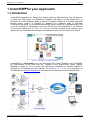
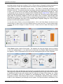
Enjoy all the benefits of a traditional HMI on Windows PC, CE and Mobile. InstantHMI 6.x is ‘Cloud Ready’ so you can also
benefit from Cloud Computing. Use GoToMyHMI: our ‘HMI-Gateway in the Cloud’ from any Browser on any device (iPad,
iPhone, Android, BlackBerry, Laptop PC, etc.) to access your HMI-Server (InstantHMI 6.x Runtime installed on Windows
PC or Windows CE touch panels). GoToMyHMI (for Windows 8) has received ‘Top App Award’ from Microsoft.
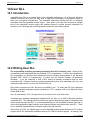
Highlights of InstantHMI
•
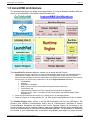
‘Design Once, Deploy Anywhere’ platform scalable new generation HMI Technology for Windows PC, Windows
CE (touch panels), PDA (Pocket PC and Windows Mobile) and Smart Phone Platforms.
•
All the powerful and convenient features that you expect in a standard PC-based HMI-technology: Monitoring,
Data Logging, Real Time & Historic Trending, Alarm Management, Reporting, Control, etc.
•
The Windows PC based LaunchPad Development System is used to design Project screens and Tag database to
be deployed on any of the target platforms with InstantHMI Runtime engine. The LaunchPad allows pre-testing of
the tags and screens on the Windows PC platform before deploying on the target PC, CE or PDA platform.
•
InstantHMI 6.1 provides ‘Anytime, Anywhere’ connectivity to process and machine control information.
•
Ease of ‘language localization’ brings our multi-platform HMI solution, to any Unicode supported language.
Why Upgrade to InstantHMI 6.1: Users of earlier versions of InstantHMI can transfer their project (Tag databases, screens,
etc.) easily to InstantHMI 6.1 framework and benefit from the new functionality (see selected list below).
Selected Feature Benefits of InstantHMI:
• The screen data object display format is independent of the raw data of the tag object in the Tag Database. You can view
data from a data source in different formats on one or more screens.
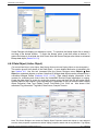
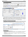
• Enhanced Data Table Viewer in Screen Designer to monitor/modify tags and transfer to the Tag Database (5.0.9).
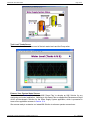
• Real Time and Historic Trend Plots on PDA as well as PC, Alarm Logging Object , enhanced Tanks, Scales, Gauges,
Faders, Knobs, and other widgets, Print Screen feature for 'Instant Runtime Status Dump' (4.1)
• Project Protection to prevent screen/tag modifications and provide intellectual property protection for OEMs (4.1)
• Scripting tool is enhanced. You may use any (long) variable names for local and global variables (4.2, 5.0).
• OLE, COM, ActiveX component support enhanced with improved user interface and functionality (4.2, 5.0)
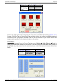
• Use dynamic runtime association of Object Assemblies with multiple Tag Groups for streamlined monitoring of similar
sub-systems (5.0.5 - 5.0.9). Object Assembly with assignable tags (5.1) and copies with assigned tag groups (6.1.29).
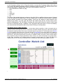
• Use Watch Lists in Runtime to monitor/modify controller tags from different groups (5.0.5 - 5.0.8). A single watch list (in
an object assembly) can provide a comprehensive, yet simple, interface to let you monitor thousands of tag variables, for
dozens of controller stations in a concise and familiar manner (like browsing through the Controller user manuals).
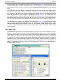
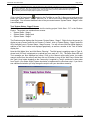
• New Project Wizard guides you step by step to quickly create and run a new project in minutes (5.0.9).
• Enhanced Widgets (Buttons, LEDs, Gauge, Knob, Active Box, Active Circle etc.) with settable properties and testable
preview (5.0.10 - 5.1.5).
• Enhanced Recipe Manager with Recipe Templates and Recipe Names for Design and Runtime ease of use (5.0.16).
• Enhanced Macro Manager with a new macro database and an enhanced Script Editor (5.1.4). These utilities are
accessible directly from the LaunchPad as well as from Screen Designer.
• Enhanced Help System (F1 key most anywhere) for Design and Runtime ease of use (5.1.4).
• Image formats may be .bmp, .jpg, .gif or .png (5.1.4).
• ‘Cloud Ready’ for remote access from any standard browser (iPad, iPhone, BlackBerry, Laptop PC, etc.) (6.x).
• PgUp/PgDn to switch to next/previous project screens in Screen Designer (6.x).
• Text, Box, Circle, V/H Bar, V/H Meter objects with Rotation and Shading attributes (6.x).
• Attribute Tags may be assigned to objects to dynamically set ‘Visibility’ property for objects; this property provides the
capability to design ‘pop-up windows’ at runtime.
• Screen Objects and entire screen may be pre-tested for communication errors in the Designer (6.1).
• InstantHMI 6.1 supports Alarm Management Features compatible with ANSI/ISA - 18.2 - 2009 standards, a Task
Scheduler that eliminates need for Scripting in Reporting etc., and RTF (fonts, colors, pictures, …) in Report Templates.
• Windows Key management (Ctrl+Alt+Del, Task Bar control, etc.) implemented (6.1.20).
• Logging data into user created Excel sheets and filtering seleted columns and rows for customized reporting (6.1.20).
• Streamlined database design for Data logging with dynamic compression and archiving allows millions of records to be
logged/analyzed over days and months (6.1.21).
• Mini-LaunchPad added to CE runtime platform for ease of modifying Data Source etc. after project deployment (6.1.27).
• Comm Interface re-architected for multi-core multi-threaded parallel processing of all communication channels (6.1.29).
• Tag Access Levels 1-10 allow control of user inputs; user input changes are logged for any specified tag(s) (6.1.30).
• Runtime API allows user written program to read the alarm status of tags being monitored by the Runtime (6.1.31).
• Multiple (dual) monitor support in Runtime lets users view and control multiple (two) screens simultaneously (6.1.31).
• All known and customer reported bugs have been fixed and many feature requests implemented.
We appreciate the feedback from our valued customers. With these enhancements, its 'Simpler is Better' architecture, and
being ‘Cloud Ready’, InstantHMI hopes to be your preferred HMI/SCADA solution on the ground and in the cloud.
The InstantHMI 6.1 Development Team
SOFTWARE HORIZONS INC. InstantHMI® PROGRAM LICENSE AGREEMENT
YOU SHOULD CAREFULLY READ THE FOLLOWING TERMS AND CONDITIONS BEFORE USING THIS PACKAGE. IF YOU
DO NOT AGREE WITH THEM, PROMPTLY RETURN THE PACKAGE UNUSED WITHIN 10 DAYS AND YOUR MONEY WILL
BE REFUNDED. USING THIS PACKAGE INDICATES YOUR ACCEPTANCE OF THESE TERMS AND CONDITIONS.
Software Horizons Inc. (SH) provides InstantHMI (the "Program") and licenses its use pursuant to license agreements. You
assume responsibility for the selection of the Program to achieve your intended results, and for the installation, use, and results
obtained from the Program. You may a) Install and operate the Program on a single computer. b) Transfer the Program, subject
to the terms of this license, to another party if the other party agrees to accept the terms and conditions of this Agreement. If you
transfer the Program, you must at the same time either transfer all copies whether in printed or machine-readable form to the
same party or destroy any copies not transferred.
You may not: a) use, copy, modify or transfer the Program, or any copy, in whole or in part, except as expressly provided for in
this license. b) provide or allow use of the Program in any network, time sharing, multiple CPU, or multiple-user arrangements.
c) grant sub-licenses or other rights in the Program. d) reproduce the documentation.
IF YOU TRANSFER POSSESSION OF THE PROGRAM OR ANY COPY TO ANOTHER PARTY, YOUR LICENSE IS
AUTOMATICALLY TERMINATED.
TERM: This license is effective until terminated. You may terminate it at any other time by destroying the Program together with
all copies in any form. It will also terminate upon conditions set forth elsewhere in this Agreement. You agree upon such
termination to destroy the Program together with all copies in any form. No refunds will be made on termination of license.
LIMITED WARRANTY: SH warrants the diskette(s) and computer chips on which the Program is furnished to be free from
defects in materials and workmanship under normal use for a period of ninety (90) days from the date of delivery to you as
evidenced by a copy of your receipt. However, SH does not warrant that the Program will meet your requirements or that the
operation of the Program will be uninterrupted or error free.
THE PROGRAM IS PROVIDED "AS IS" WITHOUT ANY WARRANTY, EXCEPT AS STATED ABOVE, OF ANY KIND, EITHER
EXPRESSED OR IMPLIED, INCLUDING, BUT NOT LIMITED TO THE IMPLIED WARRANTIES OF MERCHANTABILITY AND
FITNESS FOR A PARTICULAR PURPOSE. THE ENTIRE RISK AS TO THE QUALITY AND PERFORMANCE OF THE
PROGRAM IS WITH YOU.
LIMITATIONS OF REMEDIES: SH's entire liability and your exclusive remedy shall be: the replacement of any diskette(s)
and/or chips not meeting SH's "Limited Warranty" and which is returned to SH with a copy of your receipt.
IN NO EVENT WILL SH BE LIABLE TO YOU FOR DAMAGES, INCLUDING ANY LOST PROFITS, LOST MONIES OR OTHER
INCIDENTAL OR CONSEQUENTIAL DAMAGES ARISING OUT OF THE USE OR INABILITY TO USE (INCLUDING BUT NOT
LIMITED TO LOSS OF DATA OR DATA BEING RENDERED INACCURATE OR LOSSES SUSTAINED BY THIRD PARTIES
OR A FAILURE OF THE PROGRAM TO OPERATE WITH PROGRAMS NOT DISTRIBUTED BY SH) SUCH PROGRAM EVEN
IF SH HAS BEEN ADVISED OF THE POSSIBILITY OF SUCH DAMAGES, OR FOR ANY CLAIM BY ANY OTHER PARTY.
SOME STATES DO NOT ALLOW THE LIMITATION OR EXCLUSION OF LIABILITY FOR INCIDENTAL OR CONSEQUENTIAL
DAMAGES OR IMPLIED WARRANTIES SO THE ABOVE LIMITATION OR EXCLUSION MAY NOT, IN WHOLE OR IN PART,
APPLY TO YOU.
GENERAL: You may not sublicense, assign or transfer this license or the Program except as expressly provided in this
Agreement. Any attempt otherwise to sublicense, assign, or transfer any of the rights, duties or obligations hereunder is void.
This Agreement shall be governed by the laws of the Commonwealth of Massachusetts.
Should you have any questions concerning this Agreement, you may contact SH by writing to Software Horizons Inc., 100
Treble Cove Road, N. Billerica, Massachusetts 01862.
YOU ACKNOWLEDGE THAT YOU HAVE READ THIS AGREEMENT, UNDERSTAND IT AND AGREE TO BE BOUND BY ITS
TERMS AND CONDITIONS. YOU FURTHER AGREE THAT IT IS THE COMPLETE AND EXCLUSIVE STATEMENT OF THE
AGREEMENT BETWEEN US, WHICH SUPERSEDES ANY PROPOSAL OR PRIOR AGREEMENT, ORAL OR WRITTEN, AND
ANY OTHER COMMUNICATIONS BETWEEN YOU AND SH RELATING TO THE SUBJECT MATTER OF THIS AGREEMENT.
U.S. Government Restricted Rights. The SOFTWARE and documentation are provided with RESTRICTED RIGHTS. Use,
duplication, or disclosure by the United States Government is subject to restrictions as set forth in subparagraph (c)(1)(ii) of The
Rights in Technical Data and Computer Software clause at DFARS 252.227-7013 or subparagraphs (c)(1) and (2) of the
Commercial Computer Software--Restricted Rights at 48 CFR 52.227-19, as applicable. Manufacturer is Software Horizons
Inc., 100 Treble Cove Road, N. Billerica, MA 01862, USA.
Table of Contents
1 InstantHMI® for your Application ................................................................................................................................... 1-1 1.1 Introduction ............................................................................................................................................................ 1-1 1.2 InstantHMI Design and Runtime Platforms ............................................................................................................ 1-2 1.3 InstantHMI Runtime in Traditional HMI Scenarios ................................................................................................. 1-3 1.3.1 InstantHMI Runtime on a PC (or CE touch panel) accessing controllers ........................................................ 1-4 1.3.2 InstantHMI Client (Runtime PC) connected to InstantHMI Server .................................................................. 1-4 1.3.3 Wi-Fi Client connected to InstantHMI Server via Wireless Router .................................................................. 1-5 1.4 Moving to the Cloud: GoToMyHMI......................................................................................................................... 1-5 1.4.1 InstantHMI Server Connection for Internet Access ......................................................................................... 1-6 1.4.2 InstantHMI Server ‘GoToMyHMI Gateway’ Setup........................................................................................... 1-6 1.4.3 GoToMyHMI Services ..................................................................................................................................... 1-7 1.5 InstantHMI Architecture ......................................................................................................................................... 1-8 1.6 Get Started Immediately ........................................................................................................................................ 1-10 2 LaunchPad Development System................................................................................................................................. 2-1 2.1 Help ....................................................................................................................................................................... 2-2 2.2 Login ...................................................................................................................................................................... 2-4 2.3 Design ................................................................................................................................................................... 2-5 2.3.1 Design Æ Screens .......................................................................................................................................... 2-5 2.3.2 Design Æ Screen Æ Troubleshoot Scripts ..................................................................................................... 2-6 2.3.3 Design Æ Reports .......................................................................................................................................... 2-7 2.3.4 Design Æ Tags ............................................................................................................................................... 2-8 2.3.5 Design Æ Data Sources ................................................................................................................................. 2-10 2.4 Setup ..................................................................................................................................................................... 2-11 2.4.1 Setup Æ Project (New, Remove, Platform)..................................................................................................... 2-12 2.4.2 Setup Æ Project Æ Users ............................................................................................................................... 2-16 2.4.3 Setup Æ Project Æ Protect ............................................................................................................................. 2-16 2.4.4 Setup Æ Project Æ Deploy ............................................................................................................................. 2-18 2.4.5 Setup Æ Screens ............................................................................................................................................ 2-19 2.4.6 Setup Æ Reports ............................................................................................................................................ 2-20 2.4.7 Setup Æ Special Tags .................................................................................................................................... 2-20 2.5 Run ........................................................................................................................................................................ 2-21 2.5.1 Project Overview............................................................................................................................................. 2-22 2.5.2 Project Runtime Options ................................................................................................................................. 2-22 2.5.3 Run/Emulate Project ....................................................................................................................................... 2-23 2.5.4 Project Reports ............................................................................................................................................... 2-24 2.6 Exit......................................................................................................................................................................... 2-26 2.7 Mini-LaunchPad (InstantHMI LaunchPad for CE) .................................................................................................. 2-26 2.7.1 Help ................................................................................................................................................................ 2-27 2.7.2 Design ............................................................................................................................................................ 2-27 2.7.3 Setup .............................................................................................................................................................. 2-28 2.7.4 Run ................................................................................................................................................................. 2-28 2.7.5 Exit .................................................................................................................................................................. 2-28 2.8 Micro-LaunchPad (InstantHMI LaunchPad for PDA) ............................................................................................. 2-28 2.8.1 Help ................................................................................................................................................................ 2-29 2.8.2 Design ............................................................................................................................................................ 2-30 2.8.3 Setup .............................................................................................................................................................. 2-33 2.8.4 Run ................................................................................................................................................................. 2-33 2.8.5 Exit .................................................................................................................................................................. 2-33 2.9 Windows OS Access Control from Runtime .......................................................................................................... 2-33 3 Databases .................................................................................................................................................................... 3-1 3.1 Data Sources ......................................................................................................................................................... 3-2 3.2 Data Table Viewer ................................................................................................................................................. 3-3 3.2.1 Data Viewer (PC) ............................................................................................................................................ 3-4 3.2.2 Data Table Tool (PDA) ................................................................................................................................... 3-4 3.3 Tag Database ........................................................................................................................................................ 3-5 3.3.1 Tag Database Manager (PC) .......................................................................................................................... 3-5 3.3.2 Tag Group Functions (PC) ............................................................................................................................. 3-6 3.3.3 Tag Alias (PC) ................................................................................................................................................ 3-6 3.3.4 Tag Editor (PC) ............................................................................................................................................... 3-6 3.3.5 Tag Database Manager (PDAs)...................................................................................................................... 3-12 3.3.6 Tag Group Functions (PDAs).......................................................................................................................... 3-13 3.3.7 Tag Editor (PDAs)........................................................................................................................................... 3-14 3.4 Message Database ................................................................................................................................................ 3-18 3.4.1 Message Database Manager (PC) ................................................................................................................. 3-18 3.4.2 Message Database Manager (PDAs) ............................................................................................................. 3-19 3.5 Image Database (Bitmap, JPEG, GIF)................................................................................................................... 3-20 3.5.1 Image Capture Utility ...................................................................................................................................... 3-20 3.5.2 Image Groups (PC) ......................................................................................................................................... 3-21 3.5.3 Image Groups (PDAs) .................................................................................................................................... 3-22 3.6 Recipes and Configurations ................................................................................................................................... 3-22 3.6.1 Recipes (PC) .................................................................................................................................................. 3-22 3.6.2 Recipes (PDA) ................................................................................................................................................ 3-23 3.6.3 Configurations (PC) ........................................................................................................................................ 3-24 3.6.4 Configurations (PDA) ...................................................................................................................................... 3-25 3.6.5 Examples ........................................................................................................................................................ 3-26 3.7 Data Logs .............................................................................................................................................................. 3-28 3.7.1 Overview of Methods to Log Data in InstantHMI............................................................................................. 3-28 3.7.2 Datalog Database (Old Design – version 6.1.12)............................................................................................ 3-28 3.7.3 Template Database (for Access) .................................................................................................................... 3-29 3.7.4 Template Database (for MySQL) .................................................................................................................... 3-30 3.7.5 DSN Configuration Setup (MS Access) .......................................................................................................... 3-30 3.7.6 DSN Configuration Setup (MySQL) ................................................................................................................ 3-32 3.7.7 Data Log Triggers ........................................................................................................................................... 3-34 3.7.8 Time Based Data Logging .............................................................................................................................. 3-34 3.7.9 Event Triggered Data Logging ........................................................................................................................ 3-35 3.7.10 Event Trigger using Task Scheduled Script or Macro ................................................................................... 3-36 3.7.11 Viewing Logged Data .................................................................................................................................... 3-36 3.7.12 Viewing Database Error Log ......................................................................................................................... 3-37 3.7.13 Datalog Database (New Design – version 6.1.22) ........................................................................................ 3-37 3.8 Alarm Configuration Database and Alarm Logs ..................................................................................................... 3-39 3.9 Database Info ........................................................................................................................................................ 3-39 4 Screen Designer ........................................................................................................................................................... 4-1 4.1 Getting Started....................................................................................................................................................... 4-1 4.1.1 Title Bar .......................................................................................................................................................... 4-2 4.1.2 Status Bar ....................................................................................................................................................... 4-3 4.1.3 Tool Bar .......................................................................................................................................................... 4-3 4.1.4 Style Bar ......................................................................................................................................................... 4-4 4.1.5 Menu Bar (Main Menu) ................................................................................................................................... 4-5 4.1.6 Creating Application Screens.......................................................................................................................... 4-6 4.2 File ......................................................................................................................................................................... 4-7 4.3 Edit ........................................................................................................................................................................ 4-8 4.3.1 Redraw ........................................................................................................................................................... 4-9 4.3.2 Undo (Ctrl + z) and Redo (Ctrl + y) ................................................................................................................. 4-9 4.3.3 Move Object.................................................................................................................................................... 4-10 4.3.4 Copy Object .................................................................................................................................................... 4-10 4.3.5 Delete Object .................................................................................................................................................. 4-10 4.3.6 Make Object Assembly ................................................................................................................................... 4-10 4.3.7 Break Object Assembly .................................................................................................................................. 4-13 4.3.8 Arrange Objects .............................................................................................................................................. 4-14 4.4 View ....................................................................................................................................................................... 4-14 4.5 Tag Data ................................................................................................................................................................ 4-15 4.6 Objects .................................................................................................................................................................. 4-15 4.6.1 Static Objects.................................................................................................................................................. 4-15 4.6.2 Data Object (Active Object) ............................................................................................................................ 4-22 4.6.3 Watch List ....................................................................................................................................................... 4-23 4.6.4 Object Assembly ............................................................................................................................................. 4-25 4.6.5 Touch Zone Object ......................................................................................................................................... 4-30 4.6.6 Text Scroll Object ........................................................................................................................................... 4-32 4.6.7 Alarm Viewer Object ....................................................................................................................................... 4-32 4.6.8 Real Time/Historic Trend ................................................................................................................................ 4-33 4.6.9 OLE Object ..................................................................................................................................................... 4-35 4.6.10 ActiveX Object .............................................................................................................................................. 4-37 4.6.11 OLE/ActiveX Verbs ....................................................................................................................................... 4-41 4.6.12 Spreadsheet Viewer Object .......................................................................................................................... 4-41 4.7 Format ................................................................................................................................................................... 4-42 4.7.1 Patterns .......................................................................................................................................................... 4-42 4.7.2 Color ............................................................................................................................................................... 4-43 4.7.3 Font ................................................................................................................................................................ 4-45 4.8 Tools ...................................................................................................................................................................... 4-45 4.9 Options .................................................................................................................................................................. 4-45 4.9.1 Tabbing Order Option ..................................................................................................................................... 4-45 4.9.2 Customization Option ..................................................................................................................................... 4-46 4.9.3 Password Option ............................................................................................................................................ 4-47 4.10 Help ..................................................................................................................................................................... 4-47 4.11 Create Data Display Object ................................................................................................................................. 4-48 4.11.1 Data Type ..................................................................................................................................................... 4-50 4.11.2 Text Data Format .......................................................................................................................................... 4-52 4.11.3 Graphic Data Format - Input Widgets ........................................................................................................... 4-55 4.11.4 Clipboard Tools............................................................................................................................................. 4-58 4.11.5 Graphic Data Format - Monitor Widgets ....................................................................................................... 4-61 4.11.6 Color and Font .............................................................................................................................................. 4-66 4.11.7 Sample Time................................................................................................................................................. 4-66 4.11.8 Script ............................................................................................................................................................ 4-66 4.11.9 Remark ......................................................................................................................................................... 4-66 4.11.10 OK and Cancel ........................................................................................................................................... 4-67 4.12 Create Pop-Up Display Window .......................................................................................................................... 4-67 4.13 Edit Data Display Object ...................................................................................................................................... 4-69 4.14 Document Data Display Object ............................................................................................................................ 4-69 5 Report Designer............................................................................................................................................................ 5-1 5.1 Getting Started....................................................................................................................................................... 5-1 5.2 Main Menu (Menu Bar) .......................................................................................................................................... 5-3 5.2.1 File .................................................................................................................................................................. 5-4 5.2.2 Edit ................................................................................................................................................................. 5-5 5.2.3 View ................................................................................................................................................................ 5-6 5.2.4 Insert ............................................................................................................................................................... 5-9 5.2.5 Tag Data Field ................................................................................................................................................ 5-9 5.2.6 Help ................................................................................................................................................................ 5-11 5.3 Spooling ................................................................................................................................................................. 5-11 5.3.1 Naming Spool Templates ............................................................................................................................... 5-12 5.3.2 How Does Spooling Work? ............................................................................................................................. 5-12 5.3.3 Spool Register Functions ................................................................................................................................ 5-13 5.3.4 Data Logging using Spool Register Functions ................................................................................................ 5-17 5.4 Creating Reports at Runtime ................................................................................................................................. 5-18 5.4.1 Using Reports Æ Print Menu at Runtime ........................................................................................................ 5-18 5.4.2 Using Reports Æ Spool Menu at Runtime ...................................................................................................... 5-19 5.4.3 Using Spooled Data in Printer Reports ........................................................................................................... 5-19 5.5 Creating, Viewing and Printing Graphical Reports ................................................................................................. 5-19 5.5.1 Creating Graphical Report Templates in Screen Designer ............................................................................. 5-19 5.5.2 Report Viewer to Preview Reports in Runtime ................................................................................................ 5-20 5.6 Excel Reporting in InstantHMI ............................................................................................................................... 5-20 5.6.1 The Implementation Steps .............................................................................................................................. 5-20 5.6.2 Sample Project and Excel Report Output ....................................................................................................... 5-24 5.6.3 Extracting Data from Excel Report for a Custom Report ................................................................................ 5-25 6 Macro Manager............................................................................................................................................................. 6-1 6.1 Macro Viewer ......................................................................................................................................................... 6-1 6.2 Macro Editor .......................................................................................................................................................... 6-2 6.2.1 Move Up/Down Macro Command ................................................................................................................... 6-3 6.2.2 New Macro...................................................................................................................................................... 6-3 6.2.3 Edit Macro....................................................................................................................................................... 6-3 6.2.4 Delete Macro .................................................................................................................................................. 6-4 6.2.5 Copy Macro .................................................................................................................................................... 6-4 6.2.6 Save Macro Database .................................................................................................................................... 6-4 6.3 Macro Commands ................................................................................................................................................. 6-4 6.4 Macro Example ...................................................................................................................................................... 6-7 7 Script Editor .................................................................................................................................................................. 7-1 7.1 Getting Started....................................................................................................................................................... 7-1 7.2 Script Elements...................................................................................................................................................... 7-1 7.2.1 Variables and Keywords ................................................................................................................................. 7-3 7.2.2 Operators ........................................................................................................................................................ 7-3 7.2.3 Functions ........................................................................................................................................................ 7-3 7.2.4 Expression ...................................................................................................................................................... 7-13 7.2.5 Assignment Statement .................................................................................................................................... 7-13 7.2.6 Label and Comments ...................................................................................................................................... 7-13 7.2.7 Control Statement ........................................................................................................................................... 7-13 7.3 Examples ............................................................................................................................................................... 7-14 7.4 Error Messages ..................................................................................................................................................... 7-20 8 Communication Interface .............................................................................................................................................. 8-1 8.1 InstantHMI Communication Manager .................................................................................................................... 8-1 8.1.1 Organization of Polled Tags ........................................................................................................................... 8-2 8.1.2 Polling Mechanism .......................................................................................................................................... 8-3 8.1.3 Runtime States ............................................................................................................................................... 8-3 8.1.4 Performance Metrics ....................................................................................................................................... 8-4 8.1.5 Setup Parameters for Comm Manager ........................................................................................................... 8-4 8.1.6 Test Results .................................................................................................................................................... 8-4 8.1.7 Comm Error Logs ........................................................................................................................................... 8-6 8.2 RS-232 Signal Assignments .................................................................................................................................. 8-6 8.3 RS-232/RS-485 Serial Link using Cables .............................................................................................................. 8-6 8.4 IR Link using Infrared Kit ....................................................................................................................................... 8-6 8.5 RF-Link using RF-Kit ............................................................................................................................................. 8-7 8.6 RF-Link using Bluetooth Kit ................................................................................................................................... 8-9 8.7 Modem Communication Link ................................................................................................................................. 8-11 8.7.1 Using Modem with Unitronics PLC ................................................................................................................. 8-14 8.7.2 Trouble Shooting ............................................................................................................................................ 8-14 9 Runtime Engine (PC) .................................................................................................................................................... 9-1 9.1 Introduction ............................................................................................................................................................ 9-1 9.2 Your Application Step By Step ............................................................................................................................... 9-3 9.2.1 'Hit the Ground Running' ................................................................................................................................. 9-3 9.2.2 Methodically Design Your HMI........................................................................................................................ 9-4 9.3 Project Setup ......................................................................................................................................................... 9-5 9.3.1 Data Sources .................................................................................................................................................. 9-6 9.3.2 Screens .......................................................................................................................................................... 9-6 9.3.3 Special Tags ................................................................................................................................................... 9-7 9.3.4 File Locations.................................................................................................................................................. 9-8 9.3.5 Data Logging .................................................................................................................................................. 9-9 9.4 Runtime Menu ....................................................................................................................................................... 9-9 9.4.1 Login ............................................................................................................................................................... 9-13 9.4.2 View ................................................................................................................................................................ 9-13 9.4.3 Screens .......................................................................................................................................................... 9-13 9.4.4 Recipe ............................................................................................................................................................ 9-13 9.4.5 Configuration .................................................................................................................................................. 9-14 9.4.6 Comm Links .................................................................................................................................................... 9-15 9.4.7 Alarms ............................................................................................................................................................ 9-15 9.4.8 Reports ........................................................................................................................................................... 9-15 9.4.9 Help ................................................................................................................................................................ 9-15 9.4.10 Print/Save Screen ......................................................................................................................................... 9-16 9.4.11 Exit ................................................................................................................................................................ 9-16 9.5 System Commands ............................................................................................................................................... 9-16 9.6 Data Entry in Runtime ............................................................................................................................................ 9-18 9.6.1 Data Entry Methods ........................................................................................................................................ 9-18 9.6.2 Data Entry Access .......................................................................................................................................... 9-20 9.7 Trending ................................................................................................................................................................ 9-21 9.8 Watch Lists ............................................................................................................................................................ 9-22 9.9 Printing Reports ..................................................................................................................................................... 9-22 9.10 Touch Screen ...................................................................................................................................................... 9-22 9.11 Multiple Monitors.................................................................................................................................................. 9-22 9.12 Communications Errors ....................................................................................................................................... 9-23 10 Runtime Engine (CE and PDA)................................................................................................................................... 10-1 10.1 PDA and CE Platform Familiarity ......................................................................................................................... 10-1 10.2 Runtime Main Menu ............................................................................................................................................. 10-2 10.2.1 About InstantHMI .......................................................................................................................................... 10-2 10.2.2 Setup ............................................................................................................................................................ 10-3 10.2.3 Alarm Monitor ............................................................................................................................................... 10-3 10.2.4 Barcode Viewer ............................................................................................................................................ 10-4 10.2.5 Troubleshoot ................................................................................................................................................. 10-4 10.2.6 Login / Logout ............................................................................................................................................... 10-4 10.2.7 Exit ................................................................................................................................................................ 10-4 10.3 Data Monitoring ................................................................................................................................................... 10-5 10.3.1 Pre-formatted Screens .................................................................................................................................. 10-5 10.3.2 Graphic Monitor Screens (Designed by You)................................................................................................ 10-5 10.3.3 Bar Codes ..................................................................................................................................................... 10-5 10.3.4 Communication Errors .................................................................................................................................. 10-7 10.4 Data Logging ....................................................................................................................................................... 10-7 10.4.1 Datalog Manager .......................................................................................................................................... 10-7 10.4.2 Datalog Viewer ............................................................................................................................................. 10-8 10.4.3 Data Logging Example ................................................................................................................................. 10-9 10.5 Data Entry in Runtime .......................................................................................................................................... 10-9 10.6 Printing Reports ................................................................................................................................................... 10-11 11 TCP/IP Interface,SHIP Protocol and GoToMyHMI...................................................................................................... 11-1 11.1 Introduction .......................................................................................................................................................... 11-1 11.2 InstantHMI Client/Server Networks and SHIP Protocol ....................................................................................... 11-1 11.2.1 PC accesses Controller data over Internet ................................................................................................... 11-1 11.2.2 PC accesses Controllers connected to multiple PCs over LAN .................................................................... 11-2 11.2.3 InstantHMI TCP-IP Client Server Network .................................................................................................... 11-2 11.3 GoToMyHMI: HMI-Gateway................................................................................................................................. 11-3 11.3.1 Cloud Nodes access InstantHMI Server via GoToMyHMI ............................................................................ 11-3 11.3.2 Servers, Clients and Cloud Nodes in Perfect Harmony ................................................................................ 11-3 11.4 TCP/IP Configuration Issues................................................................................................................................ 11-4 11.4.1 TCP/IP Port Forwarding ................................................................................................................................ 11-4 11.4.2 TCP/IP Push Bit ............................................................................................................................................ 11-5 11.4.3 TCP/IP Controller Node Selection in InstantHMI Runtime ............................................................................ 11-5 11.5 TCP/IP Interface SHIP Protocol Implementation ................................................................................................. 11-7 11.5.1 TCP/IP InstantHMI Server Node ................................................................................................................... 11-8 11.5.2 TCP/IP InstantHMI Client Node .................................................................................................................... 11-9 11.5.3 TCP/IP Client Objects in Screen Designer ................................................................................................... 11-10 11.5.4 TCP/IP Device Names in Data Source Setup ............................................................................................... 11-11 11.5.5 TCP/IP Used in Project Deployment ............................................................................................................. 11-12 11.5.6 TCP/IP Chat Utility ........................................................................................................................................ 11-14 11.6 TCP/IP Interface Example ................................................................................................................................... 11-15 12 OPC Interface ............................................................................................................................................................. 12-1 12.1 Introduction .......................................................................................................................................................... 12-1 12.2 OPC Client Objects in Screen Designer .............................................................................................................. 12-2 12.3 OPC over DCOM via TCP/IP ............................................................................................................................... 12-3 12.3.1 Configure DCOM on Server PC and Client PCs ........................................................................................... 12-3 12.3.2 Configure DCOM for OPCEnum (Server PC) ............................................................................................... 12-7 12.3.3 Configure DCOM for OPCEnum (Client PC)................................................................................................. 12-9 12.3.4 Domains vs. Workgroups .............................................................................................................................. 12-11 12.3.5 DCOM over TCP/IP Protocol with NetBIOS .................................................................................................. 12-12 12.4 Example: DCOM for UniOPC Server ................................................................................................................... 12-14 12.4.1 Configure DCOM on Server PC .................................................................................................................... 12-14 12.4.2 Configure DCOM on Client PC ..................................................................................................................... 12-16 13 Historic Trend Utility.................................................................................................................................................... 13-1 13.1 Datalog Database Considerations ....................................................................................................................... 13-1 13.2 Installation Considerations ................................................................................................................................... 13-2 13.3 IHMITrend Program Elements ............................................................................................................................. 13-3 13.3.1 IHMITrend Window ....................................................................................................................................... 13-3 13.3.2 Profile Specification Dialog ........................................................................................................................... 13-4 13.3.3 Main Menu .................................................................................................................................................... 13-5 13.3.4 File Menu ...................................................................................................................................................... 13-5 13.3.5 Help Menu .................................................................................................................................................... 13-6 13.4 Application Data for Historic Trending ................................................................................................................. 13-6 13.4.1 Application Example ..................................................................................................................................... 13-6 13.4.2 Log Application Data ..................................................................................................................................... 13-6 13.4.3 Analyze Logged Data ................................................................................................................................... 13-7 14 User DLL .................................................................................................................................................................... 14-1 14.1 Introduction .......................................................................................................................................................... 14-1 14.2 Writing User DLL ................................................................................................................................................. 14-1 14.3 Skeleton User DLL............................................................................................................................................... 14-2 14.4 Special Considerations ........................................................................................................................................ 14-4 14.5 Example 1: Read / Write PLC Data Using Tags .................................................................................................. 14-4 14.6 Example 2: Read / Write PLC Data Without Tags ............................................................................................... 14-7 14.7 Example 3:Time Triggered Spooling .................................................................................................................... 14-9 14.7.1 Introduction ................................................................................................................................................... 14-9 14.7.2 Use of Time Triggered User DLL .................................................................................................................. 14-9 14.8 Example 4:Time-Triggered Control ...................................................................................................................... 14-10 14.8.1 Introduction ................................................................................................................................................... 14-10 14.8.2 Use of User DLL ........................................................................................................................................... 14-10 14.8.3 Application to Watlow Controllers ................................................................................................................. 14-11 14.9 Example 5:Commercial Laundry Controller ......................................................................................................... 14-12 14.9.1 Introduction ................................................................................................................................................... 14-12 14.9.2 Laundry Application Time Line of Activity ..................................................................................................... 14-12 14.9.3 User DLL Overview....................................................................................................................................... 14-12 14.9.4 User DLL Project File Descriptions ............................................................................................................... 14-14 14.9.5 User DLL Classes ......................................................................................................................................... 14-15 14.9.6 Remarks ....................................................................................................................................................... 14-15 15 Quick Start Guide - Training Objectives ...................................................................................................................... 15-1 15.1 Introduction .......................................................................................................................................................... 15-1 15.2 Test Communications with Your PLC .................................................................................................................. 15-2 15.2.1 Step 1: Create New Project .......................................................................................................................... 15-2 15.2.2 Step 2: Define Data Source .......................................................................................................................... 15-2 15.2.3 Step 3: Identify Tags ..................................................................................................................................... 15-3 15.2.4 Step 4: Design Screen .................................................................................................................................. 15-3 15.2.5 Step 5: Test Screen in Runtime .................................................................................................................... 15-4 15.3 Sample Application: Water Supply System .......................................................................................................... 15-5 15.4 InstantHMI Solution: Water Supply System (PC) ................................................................................................. 15-5 15.4.1 System Status - Stage 1 (PC) ....................................................................................................................... 15-6 15.4.2 System Status - Stage 2 (PC) ....................................................................................................................... 15-13 15.4.3 System Status - Stage 3 (PC) ....................................................................................................................... 15-17 15.4.4 System Status - Stage 4 (PC) ....................................................................................................................... 15-19 15.4.5 System Status (PC) ...................................................................................................................................... 15-20 15.4.6 Tank Level Trends (PC) ................................................................................................................................ 15-20 15.4.7 Water Supply System Solution - PC Runtime Platform ................................................................................. 15-23 15.5 InstantHMI Solution: Water Supply System (PPC) .............................................................................................. 15-28 15.6 InstantHMI Solution: Water Supply System (CE) ................................................................................................. 15-30 16 Task Scheduler in Runtime ......................................................................................................................................... 16-1 16.1 Reporting Task: Hourly Spooling and Daily Archiving .......................................................................................... 16-1 16.1.1 Assign Spool Templates: LaunchPad Æ Setup Æ Reports .......................................................................... 16-1 16.1.2 Create Spool Register Tag: LaunchPad Æ Setup Æ Special Tags .............................................................. 16-2 16.1.3 Incorporate Report Viewer: Screen Designer Æ Spreadsheet Viewer .......................................................... 16-2 16.1.4 Implement Runtime Script............................................................................................................................. 16-3 16.1.5 Design Spool Templates ............................................................................................................................... 16-6 16.1.6 How Does Spooling Work? ........................................................................................................................... 16-6 16.2 Reporting Task: Implementation using Task Scheduler....................................................................................... 16-8 16.2.1 Assign Spool Templates: LaunchPad Æ Setup Æ Reports .......................................................................... 16-9 16.2.2 Create Spool Register Tag: LaunchPad Æ Setup Æ Special Tags .............................................................. 16-9 16.2.3 Incorporate Report Viewer: Screen Designer Æ Spreadsheet Viewer .......................................................... 16-9 16.2.4 Implement Runtime Script............................................................................................................................. 16-9 16.2.5 Design Spool Templates ............................................................................................................................... 16-9 16.2.6 Schedule Tasks to Spool and Archive Reports ............................................................................................. 16-9 16.3 Task Scheduler Makes Reporting Task Easy ...................................................................................................... 16-13 17 Alarm Management .................................................................................................................................................... 17-1 17.1 Overview .............................................................................................................................................................. 17-1 17.2 Alarm Database ................................................................................................................................................... 17-1 17.2.1 Alarm Priority ................................................................................................................................................ 17-2 17.2.2 Alarm Zone ................................................................................................................................................... 17-2 17.2.3 Alarm Condition ............................................................................................................................................ 17-2 17.2.4 Alarm Type ................................................................................................................................................... 17-3 17.2.5 Alarm Setpoint .............................................................................................................................................. 17-3 17.2.6 Alarm Dead Band ......................................................................................................................................... 17-3 17.2.7 Alarm On Delay ............................................................................................................................................ 17-3 17.2.8 Alarm Off Delay ............................................................................................................................................ 17-4 17.2.9 Alarm Annunciations ..................................................................................................................................... 17-4 17.2.10 Alarm Message ........................................................................................................................................... 17-4 17.2.11 Alarm Annotation ........................................................................................................................................ 17-4 17.3 Alarm Manager .................................................................................................................................................... 17-4 17.3.1 Alarm Configuration ...................................................................................................................................... 17-5 17.3.2 Alarm Annunciation ....................................................................................................................................... 17-6 17.3.3 Email Configuration and Contact Database .................................................................................................. 17-7 17.4 Export/ Import Alarm Configurations .................................................................................................................... 17-10 17.4.1 Export Alarm Configurations ......................................................................................................................... 17-10 17.4.2 Import Alarm Configurations ......................................................................................................................... 17-11 17.5 Alarm Viewer in Runtime ..................................................................................................................................... 17-13 17.5.1 Filter and View Alarms .................................................................................................................................. 17-14 17.5.2 Acknowledging Alarms ................................................................................................................................. 17-14 17.5.3 Annotating Alarms ........................................................................................................................................ 17-14 17.5.4 Suppressing Alarms ..................................................................................................................................... 17-14 17.5.5 Viewing and Printing Alarm Logs .................................................................................................................. 17-15 17.5.6 Troubleshooting ............................................................................................................................................ 17-15 17.6 Alarm Documentation and Rationalization ........................................................................................................... 17-15 A. Installation, Registration and Activation ................................................................................................................... A-1 A.1 Overview .......................................................................................................................................................... A-1 A.1.1 Compatible Hardware................................................................................................................................. A-1 A.1.2 InstantHMI License Agreement .................................................................................................................. A-2 A.1.3 InstantHMI Software License Activation ..................................................................................................... A-2 A.2 Installing InstantHMI ........................................................................................................................................ A-3 A.2.1 Installing InstantHMI from Download .......................................................................................................... A-4 A.2.2 Installing InstantHMI from CD .................................................................................................................... A-9 A.2.3 Converting Old InstantHMI Projects (Version 4.x to 5.2) ............................................................................ A-10 A.2.4 Converting Old InstantHMI Projects (Version 5.2 or 6.0 to 6.1) .................................................................. A-11 A.2.5 Converting InstantHMI 6.0 Project (Software Activation) to InstantHMI 6.1 USB Key Activation ............... A-11 A.3 InstantHMI Activation Utility ............................................................................................................................. A-13 A.3.1 Introduction ................................................................................................................................................ A-13 A.3.2 Activation of PC LaunchPad Designer License .......................................................................................... A-13 A.3.2.1 Activation Modes ................................................................................................................................. A-14 A.3.2.2 Activation Process: Automatic or Manual ............................................................................................ A-14 A.3.2.3 Running LaunchPad after Activation ................................................................................................... A-16 A.3.2.4 Update Activation (Evaluation to License)........................................................................................... A-17 A.3.3 Activation of PC Runtime Engine License .................................................................................................. A-18 A.3.4 Activation of PDA Runtime Engine License................................................................................................ A-18 A.3.5 Activation of CE Runtime Engine License .................................................................................................. A-19 A.4 De-Activating InstantHMI Product License ....................................................................................................... A-19 A.4.1 Moving License Activation .......................................................................................................................... A-19 A.4.1.1 Moving PC Runtime Engine License Activation .................................................................................. A-19 A.4.1.2 Moving PC LaunchPad Designer License Activation .......................................................................... A-20 A.4.1.3 Moving CE/PDA Runtime Engine License Activation .......................................................................... A-20 A.4.2 Removing License Activation ..................................................................................................................... A-21 A.4.2.1 Removing PC LaunchPad Designer License Activation ...................................................................... A-21 A.4.2.2 Removing PC Runtime Engine License Activation .............................................................................. A-21 A.4.2.3 Removing CE/PDA Runtime Engine License Activation ..................................................................... A-21 A.5 Backing up InstantHMI Activation .................................................................................................................... A-22 A.5.1 Backing up InstantHMI PDA Activation ...................................................................................................... A-22 A.5.2 Backing up InstantHMI CE Activation ......................................................................................................... A-22 A.5.3 Backing up InstantHMI PC Activation ......................................................................................................... A-22 A.6 InstantHMI Activation using USB Key (PC only) .............................................................................................. A-22 A.6.1 New InstantHMI Installation ........................................................................................................................ A-22 A.6.2 Converting Prior Software Activation to USB Activation Key ...................................................................... A-23 A.6.3 Damaged or Lost Key Policy ...................................................................................................................... A-23 B. FAQ - Frequently Asked Questions ......................................................................................................................... B-1 B.1 What is 'InstantHMI Designed for OEM' ........................................................................................................... B-1 B.2 Assorted Questions .......................................................................................................................................... B-1 C. Communication Drivers ........................................................................................................................................... C-1 D. Solution for Your Controllers .................................................................................................................................... B.2-1 D.1 Solution for Allen-Bradley Controllers .............................................................................................................. D.1-1 D.1.1 Allen-Bradley Serial DF1 Protocol .............................................................................................................. D.1-1 D.1.2 Allen-Bradley EtherNet/IP (PCCC DF1) Protocol ....................................................................................... D.1-3 D.1.3 Allen-Bradley EtherNet/IP Protocol ............................................................................................................ D.1-5 D.1.4 Allen-Bradley Communications (Protocols and Drivers) ............................................................................. D.1-6 D.2 Solution for Modbus Controllers ....................................................................................................................... D.2-1 D.2.1 Modbus Serial RTU/Ascii Protocol ............................................................................................................. D.2-1 D.2.2 Modbus TCP Protocol ................................................................................................................................ D.2-3 D.2.3 Modbus Communications (Protocols and Drivers) ..................................................................................... D.2-4 D.3 Solution for Koyo - DirectLogic PLC ................................................................................................................. D.3-1 D.3.1 Koyo Direct Net/CCM2 Serial Protocol ....................................................................................................... D.3-1 D.3.2 Koyo Ecom - Ethernet Protocol .................................................................................................................. D.3-3 D.3.3 Koyo / DirectLogic Communications (Protocols and Drivers) ..................................................................... D.3-4 D.4 Solution for Unitronics PLC .............................................................................................................................. D.4-1 D.4.1 Unitronics Serial Protocol ........................................................................................................................... D.4-1 D.4.2 Unitronics Ethernet Protocol ....................................................................................................................... D.4-3 D.4.3 Unitronics (Protocols and Drivers) .............................................................................................................. D.4-5 D.5 Solution for Siemens PLC ................................................................................................................................ D.5-1 D.5.1 Siemens - PPI Protocol .............................................................................................................................. D.5-1 D.5.2 Siemens - MPI Protocol.............................................................................................................................. D.5-3 D.5.3 Texas Instruments PLC .............................................................................................................................. D.5-4 D.5.4 Siemens Communications (Protocols and Drivers) .................................................................................... D.5-6 D.5.5 TI Communication Protocol – Driver 01...................................................................................................... D.5-9 D.6 Solution for Mitsubishi Controllers .................................................................................................................... D.6-1 D.6.1 Mitsubishi Serial Protocol ........................................................................................................................... D.6-1 D.6.2 Mitsubishi Communications (Protocols and Drivers) .................................................................................. D.6-3 D.6.3 InstantHMI Drivers for Mitsubishi Controllers ............................................................................................. D.6-7 D.7 InstantHMI Designed for GPS Application ....................................................................................................... D.7-1 D.7.1 Introduction to GPS .................................................................................................................................... D.7-1 D.7.2 GPS Serial Protocol (NMEA) ...................................................................................................................... D.7-1 D.7.3 Example: Pipeline Monitoring Application .................................................................................................. D.7-4 D.7.4 Logged File in CSV Format ........................................................................................................................ D.7-7 D.7.5 Sample Tag Database................................................................................................................................ D.7-8 D.8 Solution for SeaLevel SeaPAC R9 Onboard I/O .............................................................................................. D.8-1 D.8.1 SeaLevel SeaPAC R9 Onboard I/O ........................................................................................................... D.8-1 D.8.2 SeaLevel SeaPAC R9 Onboard I/O Driver ................................................................................................. D.8-3 D.9 Solution for Toshiba Controllers ....................................................................................................................... D.9-1 D.9.1 Toshiba Serial Protocol .............................................................................................................................. D.9-1 D.9.2 Toshiba Ethernet (Modbus TCP) Protocol.................................................................................................. D.9-3 D.9.3 Toshiba Communications (Protocols and Drivers) ..................................................................................... D.9-4 InstantHMI for Your Application
Page 1-1
1 InstantHMI® for your Application
1.1 Introduction
InstantHMI® incorporates our “Design Once, Deploy Anywhere” HMI technology. This will allow you
to design your HMI project on a Windows PC platform, and deploy it on any Windows PC, or
Windows CE, or PDA (Windows Mobile or Pocket PC) platform, which has an installed InstantHMI
Runtime engine. Install it on Windows PC platforms for a traditional single or multi-node
Client/Server HMI setup. For a mobile/wireless solution install it directly on a Windows Mobile PDA
or use our InstantChip™ technology to run from a CF/SD card. Use InstantPanel™, our Windows
CE color touch system (5.6", 8", 10.4", 12.1" and 15.0" screens), for panel mount machine control
applications. Any InstantHMI runtime engine can stand-alone or be part of a client-server network.
Figure 1-1: InstantHMI for Your Hardware Platform
InstantHMI 6.x is ‘Cloud Ready’ so you can also benefit from Cloud Computing. Use GoToMyHMI:
our ‘HMI-Gateway in the Cloud’ from any Browser on any device (iPad, iPhone, Android,
BlackBerry, Laptop PC, etc.) to access your HMI-Server (InstantHMI 6.x Runtime installed on
Windows PC or Windows CE touch panels). See Sections 1.3, 1.4. For more information on
GoToMyHMI visit www.GoToMyHMI.com and review the information and manual available there.
Figure 1-2: GoToMyHMI: ‘HMI-Gateway in the Cloud’ puts InstantHMI in the Cloud
InstantHMI: Copyright © 2000-2014 Software Horizons Inc.
6.1 – 20Jul2014
InstantHMI for Your Application
Page 1-2
This manual covers all platforms on which InstantHMI can be deployed (Windows PC, Windows CE, Windows
Mobile, and Pocket PC). All figures and discussions are illustrated with any one of the platforms unless there
are significant differences among the implementations for the different platforms in which case the specific
platform will be identified. If a specific feature is critical for successful implementation of your project, you must
verify its availability on the platform of your choice; please contact Software Horizons for assistance.
1.2 InstantHMI Design and Runtime Platforms
InstantHMI LaunchPad allows you to design your HMI project on a Windows PC platform, and
deploy it on any Windows PC, Windows CE or PDA (Windows Mobile or Pocket PC) platform, which
has an installed InstantHMI Runtime engine. PC-based HMI is well understood and most people are
familiar with the concept. However, since 'full featured HMI' on a PDA platform is not commonly
expected and is not well understood, in the rest of this section we address some salient PDA and
CE platform issues. While InstantHMI Nodes (Runtime engines) on various platforms can interact
with each other, any InstantHMI node (including a PDA node) can stand alone; that is, PDA
based InstantHMI does not require a PC node (to act as a 'server').
Figure 1-3: Illustrating InstantHMI on Windows CE and PDA platforms
Why Deploy InstantHMI on a PDA? Mobility, low cost, and wireless connectivity are some of the reasons why
PDA based HMI can enhance your total HMI solution. We list a few illustrative scenarios below.
Scenario 1: You are the operator responsible for running your process. Your boilers are working OK but you
know you can make them work more efficiently if you could only monitor what the controller was doing. You
have that wonderful PDA (Pocket PC) in your shirt pocket. Moreover, you have InstantHMI software installed
in your PDA. You walk over to the controller cabinet, plug in the communication cable to the serial port on the
PDA, turn on the PDA, and tap the stylus over the InstantHMI icon on the touch screen. The monitoring
screen shows the Boiler Temperature and pressures for the two boilers. (If your controller has an infrared port
on it, you don’t even need a cable; just beam the PDA’s built in IR head at the controller). Of course,
InstantHMI will show any other variables that are relevant to your task at hand. You decide to look at the P-I-D
parameters for the Feed Water control loop. Tap on the screen fields to change the tag names to display the
P-I-D tags and the Set Points. Enter the new values (based on your analysis) through the screen and switch
to monitoring and log the data in the PDA for the next ten minutes or so. Go get your cup of coffee (you
earned it!), while InstantHMI is logging the data for your review.
Scenario 2: You are the operator responsible for installation and startup of a machine control system. Your
task includes verifying that the Input/Output wiring for the system is as required before the machine can go
into production. The machine includes an elaborate PC based HMI. Verification of the I/O tags and the
corresponding system response requires two persons: one setting I/O tag values on the HMI screen and the
other to observe and verify the actual system component response. But you have a mobile, wireless Pocket
PC with InstantHMI installed on it. You walk over to a location where you can observe the system
component(s) of interest, use the InstantHMI I/O tags to set the I/O values, and observe the actual system
response. Your colleague can be doing other useful tasks during this verification period rather than act as your
helper.
Scenario 3: Your process, which has been running fine for a long period of time, has started exhibiting certain
unusual behavior. You have certain ideas on what may be going wrong, but you would like to collect some
InstantHMI: Copyright © 2000-2014 Software Horizons Inc.
6.1 – 20Jul2014
InstantHMI for Your Application
Page 1-3
additional data to confirm which of your thoughts are worth pursuing further in detail. Changes or additions to
the existing, elaborate, sophisticated HMI are not feasible over the short haul. You whip out your Pocket PC
based InstantHMI, collect some data for tags of interest, independent of and without disturbing the existing
HMI, and use this information to solidify your ideas and present it to the group or management for further
action and/or enhancement of the existing elaborate HMI.
Scenario 4: With a low price for the complete system (Pocket PC hardware, RS232 serial cable, adapter and
software) now even the lowest cost “micro” PLCs and other controllers can have their own HMI.
Scenario 5: You are ‘on call’ for Alarm Management at the plant. Your company has subscribed to
GoToMyHMI services and you receive an email alert to your iPhone. You glance at your email, notice a HighHigh Temperature Alarm, click on the link to access the Alarm Page from your HMI-Server and ACK the alarm
and turn on the backup coolant pump. You saved a trip back to the factory and had a good night’s sleep.
InstantHMI runtime engine on a PDA node can 'stand alone' as it does not require a runtime engine
on a PC node to act as a 'Server'. When a runtime engine is also available on a PC or other platform
nodes, the PDA based runtime can easily exchange information with the other InstantHMI runtime
nodes in a 'Client-Server' setup.
Quick deployment of InstantHMI on a PDA platform is possible (without the need for elaborate
Project setup) if you can take advantage of the integrated Runtime and Design screens of a
traditional HMI provided in InstantHMI by the use of a tag database (organized into tag groups) and
pre-formatted screens. The Scrollable Monitor screen allows the small touch screen of the PDA to
be used to view Data Registers, I/O bits, Timer/Counter values etc. in conveniently named tag
groups. (The Data Table function allows you to view / modify controller information even when you
have not setup any tags). Parameter values such as P-I-D can be input from the PDA by touch or
with the help of a stylus (Password protection is built-in). Register and other data values can be
logged in the PDA and reviewed later.
InstantHMI is Screens and Buttons oriented to make it straightforward and easy to use. PLC
communication protocol parameters can be easily configured. The Tag Editor allows you to add,
modify or delete tags. (OEM versions come with pre-created tag database). These tags are used to
monitor and /or modify data through the runtime screen. The Tag Group Manager allows you to
organize tags into named groups; this is useful in functional grouping of tags (Recipes, Configuration
etc.). InstantHMI allows on-demand data logging of selected tags in a database which can be
reviewed on the PDA in a scrollable table or the PDA can be connected to a desktop PC at a later
time to transfer the logged data for Historic Trending, Reporting or other analysis.
InstantHMI has an architecture which supports traditional HMI screens (designed and deployed
using the LaunchPad Development system) on PDA platforms. This feature permits OEM and
machine control applications to be built using specialized screens (see Project Protection, Section
2.4.3). If you have any special applications contact us so we may adapt InstantHMI to meet your
special needs.
InstantHMI runtime installed in the PDA (Windows Mobile or Pocket PC) makes configuration,
diagnostic, trouble shooting and data logging tasks for your controller equipment as simple as
possible. The compact shirt pocket size of the PDA and the infrared beaming and wireless RF
capability incorporated in InstantHMI, provide for the greatest mobility and make InstantHMI
available ‘any time, any place’ as a human machine interface. The creation of tags may be done
directly on the PDA with InstantHMI; however, this chore is made much more convenient using the
LaunchPad's Screen Designer (Section 4) running on a Windows Desktop PC.
1.3 InstantHMI Runtime in Traditional HMI Scenarios
As you would expect from any standard HMI, InstantHMI can be used in any of the traditional HMI
scenarios described below.
InstantHMI: Copyright © 2000-2014 Software Horizons Inc.
6.1 – 20Jul2014
InstantHMI for Your Application
Page 1-4
1.3.1 InstantHMI Runtime on a PC (or CE touch panel) accessing controllers
In either scenario (PC or CE) the InstantHMI Runtime Engine renders the tag information from the
controllers in terms of HMI Project screens and provides access to all the other functionality built into
the HMI-Project.
Figure 1-4: InstantHMI Runtime accessing Data from Controllers (Windows PC and Windows CE)
1.3.2 InstantHMI Client (Runtime PC) connected to InstantHMI Server
Note: The term Client-Server is sometimes mis-understood. Here is a simple metaphor: a restaurant
scene. The Customer (Client) at the table orders food items with the Waiter (Server). The Waiter can
serve any food items (data) available from the Chef (Controller) in the Kitchen (Production Machine).
Figure 1-5: InstantHMI Client-Server Setup
In the Client-Server scenario the InstantHMI Runtime Engine on the Client uses the tag information
from the controllers served by the Server to render the HMI Project screens. The Server acts as the
Data Source for the Client and hence as a go-between the client and the controllers. Here the
connection between the Client and the Server is wired LAN and the information exchange uses the
SHIP protocol (Software Horizons’ Inter-Node Protocol); the Client may also access the Server over
the Internet (Section 1.4.1).
InstantHMI: Copyright © 2000-2014 Software Horizons Inc.
6.1 – 20Jul2014
InstantHMI for Your Application
Page 1-5
1.3.3 Wi-Fi Client connected to InstantHMI Server via Wireless Router
Similar to the previous scenario, the connection between Client 1 and the Server A is wired LAN. In
addition, here we show Client 2 (InstantHMI Runtime installed in a Wi-Fi Mobile PDA) accessing the
Server over a wireless link using a wired/wireless Router on the LAN. Both Clients interchange
information with the Server using the SHIP protocol (Software Horizons’ Inter-Node Protocol).
Figure 1-6: Wireless and Wired InstantHMI Clients connected to InstantHMI Server
1.4 Moving to the Cloud: GoToMyHMI
In Section 1.3 we described several traditional scenarios in which InstantHMI Runtime Engines may
be used. Here we make our move into the cloud and show how ‘Cloud Ready’ InstantHMI 6.x
Runtime Engines may be setup for access over the Internet and ready to use the GoToMyHMI
Services.
The first generation of GoToMyHMI incorporated an ‘HMI-Gateway in the Cloud’. This was GoToMyHMI as a SAAS
implementation with infrastructure (Server, Database, etc.) in the cloud. It was provided as a Subscription Service (monthly
or annual) to the user. This service is described in a separate document. As of January 1, 2013 this service is available
only by special license arrangement with Software Horizons.
The second generation GoToMyHMI incorporated a Web Server (GTMH-WebServer.exe) implementation that can be
described as a more general ‘HMI-Gateway’; that is, ‘HMI-Gateway to the Cloud (Internet) and LAN (Intranet)’ that requires
a Software product license for InstantHMI Runtime option ‘GoToMyHMI: Web Server’ for installation at customer site. With
this approach there is no infrastructure in the cloud. Such installation may be on the same platform as the HMI-Server
(InstantHMI Runtime on PC or CE) or another PC on the same LAN as the HMI-server. With the GoToMyHMI Web-Server
implementation InstantHMI Runtime may be remotely accessed from any web browser (iPad, iPhone, BlackBerry, Laptop
PC, etc.) over the Internet as well as over the LAN without an Internet.
Customer Perceived Advantages of GoToMyHMI Web-Server over GoToMyHMI Cloud Services:
1. No subscription fees on an on-going basis
2. Customer can enforce its own HMI-Server and Internet access policies
3. No dependence on third party cloud infra-structure
4. Sense of security that its HMI data does not leave its own hardware infrastructure
InstantHMI: Copyright © 2000-2014 Software Horizons Inc.
6.1 – 20Jul2014
InstantHMI for Your Application
Page 1-6
1.4.1 InstantHMI Server Connection for Internet Access
InstantHMI Runtime Server can also support remote Clients over the Internet using the SHIP
protocol (Software Horizons’ Inter-Node Protocol). Such remote clients include InstantHMI Runtime
installed on a Windows Platform.
Connection to the Internet requires two things:
• DNS server to resolve the domain name you are trying to access into the equivalent IP
address, and
• Gateway where your network connects to the Internet.
A Gateway or a Router facilitates communication among hosts that are not on the same logical
network (e.g. IP-subnet). The Router receives packets of data on an interface and uses a routing
table (logical network locations) to route them to their destination.
Figure 1-7: InstantHMI Server Setup for Internet Access
The function of a gateway can be performed by hardware, as in the case of Routers, or software, or
a combination of both. We use the term ‘HMI-Gateway in the Cloud’ as a metaphor representing
such a generalized gateway. An example of a software gateway is when you use GoToMyHMI
Services in order to share the Internet connection from your InstantHMI Server with multiple ‘Cloud
Nodes’. GoToMyHMI gateway not only relays information across networks, but it also performs the
‘conversion of protocols’ (i.e. HMI project screens and data to browser screen display and data). In
addition, GoToMyHMI also performs Node Access Translation (similar to, but not the same as
Network Address Translation or NAT) in order to deliver the HMI packets to its destination (from/to
InstantHMI Server to/from Cloud Nodes).
1.4.2 InstantHMI Server ‘GoToMyHMI Gateway’ Setup
To enable Cloud Node(s) access to the InstantHMI Server via the GoToMyHMI Gateway do the
following. In LaunchPad select the Project (PLC Demo, in our example), click on Design Æ Data
Sources Æ GoToMyHMI Gateway Æ GoToMyHMI Setup. This opens the GoToMyHMI Setup dialog
as shown in Figure 1-8.
InstantHMI: Copyright © 2000-2014 Software Horizons Inc.
6.1 – 20Jul2014
InstantHMI for Your Application
Page 1-7
InstantHMI 6.x is ‘Cloud Ready’. Use the check box at the top to enable GoToMyHMI Connectivity
with InstantHMI Server. Whenever the HMI-Server (your Runtime PC/CE platform) is running and
accessible from the Internet, it will be shown as on-line for remote access by Cloud Nodes;
otherwise, it will be shown as off-line.
Enter Customer ID assigned by Software Horizons when your company sets up User subscriptions
to GoToMyHMI Services. You may give a convenient name (but unique to each Server) to your
InstantHMI Server. By default all Project screens are accessible from Cloud Nodes. Select any
Screens you wish to remove from this access list and click on Remove button. Leave the Screen
Update time at the default value; it can be changed by the User at the Cloud Node to suit the
bandwidth and cost of Internet access from the Cloud Node. Enter the email address of Alarm
Recipient(s) who will receive email when an alarm condition arises on tags that are marked for alarm
email notification (in the Tag Manager). Leave the Alarm Status Update at the default 1 second or
change it as desired. By clicking the link in the alarm Emails they can remotely access the alarm
page from their Cloud Node and acknowledge selected alarms. Leave the Alarm Status Update time
at the default value (a slower update time may reduce bandwidth requirements).
Figure 1-8: LaunchPad Æ Design Æ Data Sources Æ GoToMyHMI Gateway Æ GoToMyHMI Setup
Your InstantHMI Server ‘GoToMyHMI Gateway’ Setup is then as shown in Figure 1-8. Click on Done
to complete the InstantHMI Server setup, which is now ready for cloud access over the GoToMyHMI
Gateway from any remote browser. The GoToMyHMI Setup parameters are saved in the Project.ini
file in your InstantHMI Project folder.
1.4.3 GoToMyHMI Services
GoToMyHMI Web Server (GTMH-WebServer.exe) is licensed as a Runtime option and provides the
GoToMyHMI Services without a subscription. The Services currently offered are:
•
•
•
•
GTMH/Monitor: remotely access your HMI-Server Project and monitor any screens.
GTMH/Alarm: In addition to GTMH/Monitor, remotely access the Alarm Page and ACK any
alarms.
GTMH/Control: In addition to GTMH/Alarm, remotely enter Discrete and/or Analog tag values
through Screen Objects.
GTMH/Admin: Manage your account user names and passwords etc. using GoToMyHMI
Setup. The file GTMH-WebServerUsersDb.idb contains the user information.
InstantHMI: Copyright © 2000-2014 Software Horizons Inc.
6.1 – 20Jul2014
InstantHMI for Your Application
Page 1-8
1.5 InstantHMI Architecture
The important elements in the design and implementation of a Human Machine Interface (HMI) are
shown in the InstantHMI 6.x Architecture block diagram below.
Figure 1-9: InstantHMI Architecture
The LaunchPad Development platform, enables you to design the HMI-Project.
1. Design project screens, reports etc. to suit your HMI application requirements. An InstantHMI Project
implements the 'model of the Process or Machine Control Application' for the benefit of operators,
supervisors and management who are responsible for the proper and efficient operation of the machine
and the plant. Your Project may include some or all of the Project Elements listed below:
• Tag Database,
• Screens,
• Report/Spool Templates,
• Data Sources (controller communication setup parameters and drivers),
• Project Users, and
• Target Runtime Platforms (PC, PDA, and CE) where project will be deployed.
Windows PC (XP, Vista, 7), Windows CE.NET touch panels, and Windows Mobile (PDAs,
Smartphones)
2. Setup all project elements (and users) so it is 'Ready to Run' on the target platform.
3. Deploy the project on the target platform (PC, CE, PDA) where InstantHMI Runtime Engine is installed.
The Runtime Engine allows access to all the HMI-functionality built into the HMI-Project. The
Runtime uses available Communication Link(s) and its Communication Interfaces to retrieve
Process/Machine information and renders them on the Operator Display for monitoring by the
Human Operator as well as enabling Operator input (using displayed screen objects and keyboard,
mouse or touch hardware) to control the Process/Machine operation. The information for Monitoring
and Control of your machine/process is presented using display data objects on project screens.
InstantHMI: Copyright © 2000-2014 Software Horizons Inc.
6.1 – 20Jul2014
InstantHMI for Your Application
Page 1-9
These display data objects get their parameters from a tag object in the Tag Database. Most project
screens include Macros and Scripts that make the project screens more powerful and convenient.
Reports provide information to assist supervisory and management personnel. Runtime Engine may
also log Data for Historic Trending analysis.
InstantHMI from Software Horizons implements a ‘Design Once, Deploy Anywhere’ HMI technology.
It incorporates a LaunchPad Designer to design your HMI Project which can then be deployed on
any target platform to be rendered by the InstantHMI Runtime Engine software installed on that
platform. InstantHMI incorporates a Language plug-in, which makes it ‘Language Ready’ for
localization in any language. We provide all strings to be translated in an Excel sheet ready for you
to translate; when we receive the translation it can be ‘plugged-in’ to the InstantHMI software by us.
When this is done, the Designer and the Runtime will be in your language. So if your Windows OS is
in your language then the entire HMI project design and runtime execution of your HMI project will
be entirely in your language (For example Chinese, Spanish, etc.) Please contact Software
Horizons for your language requirements and the details of our policy. In addition, InstantHMI 6.x
incorporates a Cloud plug-in to makes it ‘Cloud Ready’ so that the InstantHMI Project elements are
remotely accessible from any Browser (iPad, iPhone, Android, BlackBerry, Laptop PC, etc.).
The LaunchPad Project Management platform enables you to do everything you need in the
InstantHMI framework:
• Design project screens, reports etc. to suit your application requirements.
An InstantHMI Project implements the 'model of the Process or Machine Control Application' for the benefit
of operators, supervisors and management who are responsible for the proper and efficient operation of the
machine and the plant.
• Setup all project elements (and users) so it is 'Ready to Run'; Deploy to target platform (node), if
different from Designer node.
• RUN the project (if the target is the same PC on which the LaunchPad is installed).
The information for Monitoring and Control of your machine/process is presented using display data objects
on project screens. These display data objects get their parameters from a tag object in the Tag Database.
Most project screens include Macros and Scripts that make the project screens more powerful and
convenient. Reports can be designed to assist supervisory and management personnel.
• Help provides access to Documentation and Registration/Activation information.
Figure 1-10: LaunchPad at Startup and in Design Mode
InstantHMI Projects are managed (created, stored, deployed, etc.)using tools included in the
LaunchPad (Section 2). Critical information used to define project elements is stored in Databases
(Section 3). The LaunchPad includes a Screen Designer (Section 4), Managers for Tag Database
and Data Sources, Editors for Reports (Section 5), Macros (Section 6), and Scripts (Section 7), and
utilities such as Data Table and Screen Capture.
InstantHMI: Copyright © 2000-2014 Software Horizons Inc.
6.1 – 20Jul2014
InstantHMI for Your Application
Page 1-10
Your Project may include some or all of the Project Elements listed below:
• Tag Database (Section 2.3.4, Section 3.3),
• Screens (Section 2.3.1, Section 4),
• Report/Spool Templates (Section 2.3.3, Section 5),
• Data Sources (Section 2.3.5, Section 3.1), (controller and InstantHMI IP node address
database, communication setup parameters and drivers),
• Project Users (Section 2.4.2), and
• Target Platforms (PC, PDA, CE) where project will be deployed (Section 2.4.1).
The LaunchPad enables you to deploy InstantHMI Projects to one or more Runtime Engine
platforms of your choice: PC, PDA or Windows CE (Sections 9 and 10). The Runtime uses available
Communication Link(s) (Section 8) and its Communication Interfaces (Sections 11 and 12) to
retrieve Process/Machine information and renders them on the Operator Display for monitoring by
the Human Operator as well as enabling Operator input (using displayed screen objects and
keyboard, mouse or touch hardware) to control the Process/Machine operation. Runtime Engine
may also log Data for Historic Trending analysis (Section 13).
1.6 Get Started Immediately
• Review InstantHMI License (see front of the manual)
• Review Activation / Registration Policy, moving and removing the Activation (Appendix A)
• Install InstantHMI LaunchPad on Windows PC and the Runtime Engine on target platforms
(Windows PC, CE, Pocket PC etc.). See Appendix A for details.
• Register and Activate InstantHMI on all nodes (PDAs and Desktop)
Before proceeding further it is important that you take a minute to fill in and email, fax or mail your Registration
Form. This is the only way we have of informing you about important changes and improvements to
InstantHMI. Special update and support privileges are only available to Registered customers, so please send
in your registration form promptly.
We will get you up and running with InstantHMI and your controller on 'Day One'.
Run the InstantHMI LaunchPad. (Figure 1-10) You will see the LaunchPad with four Projects in the
pull-down list: Demo, MyProject, 'Quick Start PC', and Sample Project. You will also see a
Thumbnail view of all the screens included in the selected project (Demo).
Project
Screens*
Tags
Remarks
Demo
17
242
Includes various InstantHMI features that you can learn from.
MyProject
1
2
A minimal stub project, Template to start your own project.
Sample Project
3
18
Similar to MyProject, enhanced Template to start your own project.
Quick Start - PC
2 (+4)
21
A 'Water Supply System' application used as a training tool.
Template
0
16
Hidden project used as new project template by 'default'.
* In addition, a Watch list screen (provided automatically) may be enabled by you as a runtime option.
The Demo project includes various InstantHMI features that you can learn from. We suggest you
run the Demo project (that is, in LaunchPad select 'Demo' in the Project pull-down list and then click
RUN) and do a quick 2-minute review first. This will provide you with a quick overview of InstantHMI
features that you can benefit from. You may re-visit any screen, script etc. in the Demo project at a
later time for a detailed study.
To make it convenient for you, when you complete installing InstantHMI on your PC, the LaunchPad (which
serves as the command and control center from which you may access the main program elements of
InstantHMI) appears and presents you with an opportunity to run the 2-minute demo. Run this 2-minute Demo
to get a feel for various InstantHMI features that you can use in your own application. Throughout this manual
we will use the Demo project for illustrative purposes. We recommend that you use the Demo project elements
(Screens, Scripts, Macros, etc.) as a tool to shorten your learning curve in using InstantHMI for your
application solution. A sample screen from the Temperature Monitoring application included in the Demo
InstantHMI: Copyright © 2000-2014 Software Horizons Inc.
6.1 – 20Jul2014
InstantHMI for Your Application
Page 1-11
project (Figure 1-11) shows boiler and pump states and allows the input of Temperature Setpoint and
monitoring of (High/Low Temperature) alarm conditions.
Figure 1-11: Demo Project-Sample Screen
When you create a new project, the 'Template' folder is used as the project template by 'default'.
You may use MyProject, a minimal stub project with a simple screen and 2 (controller) tags, as a
template for your initial PLC communication testing. For your convenience, Sample Project
provides the same controller tag functionality as in MyProject but with enhancements (scaled tag
values, system date and time tags, and a runtime script simulating a simple 'Tank Level Control'
application). You may use this 'Sample Project' as a learning tool and as a template for your own
project. (Of course, the runtime script 'Runtime.sct' in 'Sample Project' should be eliminated or
replaced with logic to suit your application).
We recommend that for self-training on screen design, controller interface and project design you
refer to the separate document 'Quick Start Guide'. We include below a brief description of the
Water Supply System used in the Quick Start Guide for illustration. You may access the 'Quick Start
Guide' by clicking the Help button at the bottom left of the LaunchPad (Figure 1-10).
Figure 1-12: Application Example - Water Supply System
The Water Supply System for a small community consists of two Tanks A & B, a Well Pump, and a
Booster Pump station monitored and controlled from a central facility. Tank A supplies water to
community members living in its vicinity. Tank A draws its water from the Well by initiating a
'Required' command to the Well (Pump). Tank B supplies water to community members living in its
vicinity. Tank B draws its water from Tank A by initiating a 'Required' command to the Booster
Pump. Manual overrides are required at the central facility to operate Well Pump and Booster
Pump. All Remote sites are connected to the host central site's PLC via radio RTUs. The variables
of interest (tabulated below) are maintained and the site logic is programmed in the PLC.
Our task is to provide a Human Machine Interface for the operator(s) in the Water Supply System
facility. InstantHMI can provide such an interface on multiple platforms. The HMI solutions on these
platforms are very similar.
InstantHMI: Copyright © 2000-2014 Software Horizons Inc.
6.1 – 20Jul2014
InstantHMI: LaunchPad Development System
Page 2-1
2 LaunchPad Development System
An InstantHMI Project implements the 'model of the Process or Machine Control Application' for the
benefit of operators, supervisors and management who are responsible for the proper and efficient
operation of the machine and the plant. The project design and setup are done using the LaunchPad
HMI-Project Development and Management System.
Figure 2-1: InstantHMI LaunchPad Before Activation
Note: For customer convenience in making minor changes to Project elements, we also provide a Mini-LaunchPad running
on the CE platform (Section 2.7) and a Micro-Launchpad running on PDA (Section 2.8).
The LaunchPad includes the following Command Buttons:
• Design
• Setup
• Run
• Help
The pull-down list at the top allows you to select one of the available projects. If you select 'New
Project' here, the New Project Wizard (Section 2.4.1) pops up to guide you through creation of a
new project for your application.
Figure 2-2: InstantHMI LaunchPad After Activation
When you click on a Command Button a dialog box pops up in the LaunchPad panel, which gives
access to the associated project elements and tools. The hierarchy of project functions and the
associated Project Elements (Screens, Databases, etc.) as well as the Tool or Utility used in the
design and setup are shown in Figure 2-3.
InstantHMI: Copyright © 2000-2014 Software Horizons Inc.
6.1 – 20Jul2014
InstantHMI: LaunchPad Development System
Command
Design
Functions
Screens
Reports
Tags
Data Sources
Setup
Project
Screens
Reports
Special Tags
Run
Help
Overview
Options
Reports
Run /
EmulateTarget
Register/
Activate
Order Help
Project Elements
Screens (Thumbnail)
Screens (List
Scripts
Macros
Tasks
Recipes
Configurations
Troubleshoot Scripts
Images
Printer Reports
Spool Reports
Alarm Reports
Historic Trends
Logs
Tag Database
Alarm Database
Data Viewer
Datalog Tags
Datalog Events
Message Groups
Image Groups
Comm Links
TCP/IP Links
Remote Sites
Contact Database
Email Configuration
SHIP Client-Users
GoToMyHMI Gateway
New Project
Remove Project
Change Platform
Users
Protect
Deploy
Project Screens
Printer Report Templates
Spool Reports Templates
Print Control
Spool Control
Switch Screen
Update Enable
Recipe Enable
Project Runtime Setup
Project Runtime Reports
Page 2-2
Tool or Utility
Screen Designer
Screen Designer
Script Editor
Macro Editor
Task Scheduler
Recipe Editor
Configuration Editor
Troubleshoot Editor
Image Capture Utility
Report Designer
Report Designer
Alarm Viewer
Historic Trend Utility
Log Viewer
Tag Manager
Alarm Manager
Data Viewer
Tag Manager
Datalog Events Dialog
Message Manager
Image Manager
Data Source Manager
IP Manager
Remote Site Manager
Contact Database
Email Configuration
Client-User Manager
GoToMyHMI Setup
New Project Dialog
Remove Project Dialog
Select Platform Dialog
User Profile Manager
Project Protection Utility
Deploy, Retrieve Dialog
Screen Designer,
Add, Insert, Remove, Delete Dialog
Report Designer, Assign, Remove, Delete
Dialog
See Section
4
4
7
6
16
3.6
3.6
2.3.2
5, 16
5, 16
4.6.7
13
4.6.12
3.3
17
3.2
3.7
3.7
3.4
3.5
3.1, 8
2.3.5
17.3.3
2.4.1
2.4.2
2.4.3
2.4.4
2.4.5
2.4.6
Tag Manager, Assign, De-assign Dialog
2.4.7
Runtime Setup Dialog
Target Runtime Engine Emulation
Runtime Report Viewer
PC Runtime Engine
2.5.1
2.5.3
2.5.4
2.5.2
Designer/
Activation Utility
Runtime Engine
InstantHMI Components
InstantHMI Order Page (web)
Used
User Manual
Documentation Manual
Adobe Acrobat Viewer
Quick Start
Quick Start Guide
Figure 2-3: Project Functions, Associated Project Elements and Design Tools
2.1
2.1 Help
The LaunchPad Help command displays program version information (Figure 2-4) and also provides
three buttons: Activate, User Manual, and Quick Start. Note: If you double click the Runtime Engine
or LaunchPad items on this panel, the OEM acronym will be displayed. Standard is displayed for
the standard version meant for all non-OEM customers.
InstantHMI: Copyright © 2000-2014 Software Horizons Inc.
6.1 – 20Jul2014
InstantHMI: LaunchPad Development System
Page 2-3
Figure 2-4: LaunchPad Æ Help
The Register/Activate button allows you to create Registration information to be sent to Software
Horizons. Registration is required to receive your license activation (after your InstantHMI software
order or to request an evaluation before you order). The Order Help button presents additional
information to help you. (This button will disappear once you have Activated your license.)
Activation is essential to access all the installed features in your InstantHMI software (Appendix A).
The User Manual button displays the InstantHMI Manual (Figure 2-5). (Adobe Acrobat reader
needed to view this PDF file may be downloaded from www.InstantHMI.com/acrobat). The Quick
Start button displays the InstantHMI Quick Start Guide (PDF file).
Figure 2-5: LaunchPad Æ Help Æ User Manual
InstantHMI: Copyright © 2000-2014 Software Horizons Inc.
6.1 – 20Jul2014
InstantHMI: LaunchPad Development System
Page 2-4
2.2 Login
After the installation of InstantHMI usually an Administrator would setup Project Users (using the
User Profile Manager discussed in Section 2.4.2) with user names, passwords and access
privileges. Login password access control will be enabled when the User Manager is enabled. You
may play the role of the system administrator (using default Login User Name: Administrator,
Password: a) and setup users, passwords and assigned functions. The InstantHMI LaunchPad
maintains a registry of users, their passwords and assigned functions. The System Integrator is
responsible for setup of this registry and may designate a System Administrator at the customer site
to setup additional users, passwords and assigned functions.
Figure 2-6: LaunchPad Pop-up Dialog (Before and After Login)
To Login you may right click anywhere on LaunchPad border area to access the pop-up dialog
(Figure 2-6) and select 'Login'. If required, you must Login to access assigned InstantHMI functions.
If you try to access any protected functions requiring user authentication, the Login dialog will
appear; you may then enter your User Name and Password. Depending on your authentication
InstantHMI will allow access to the assigned functions and deny access to other unassigned
functions.
Figure 2-7: Login Dialog
After you login, you may access the pop-up dialog (Figure 2-6) to do the following:
• Change Password
• Lockout InstantHMI
• Logout
If you select 'change password' a dialog box appears: enter your old password (you used to login),
enter your new password and enter it a second time to confirm your new password selection and
then click Change.
InstantHMI: Copyright © 2000-2014 Software Horizons Inc.
6.1 – 20Jul2014
InstantHMI: LaunchPad Development System
Page 2-5
Figure 2-8: Change Password
To Logout, select 'Logout <User Name>' and enter your password. The system will default to user
‘Guest' if no one is logged. The system administrator can decide what InstantHMI functions are
accessible when user is ‘Guest’.
To leave InstantHMI in a locked state, select ' Lock InstantHMI'. A Resume Screen appears and all
LaunchPad functions are locked out until you click on Resume button and enter your password.
Figure 2-9: Locking InstantHMI LaunchPad
2.3 Design
2.3.1 Design Æ Screens
InstantHMI implements a ‘Design Once Deploy Anywhere’ technology. The project Tag Database
can be transferred to any target platform, which has an installed InstantHMI runtime engine.
Likewise, the project screens created in the Screen Designer will be transferable to Windows PC,
CE and PDA platforms. Screens for different platforms with different screen resolutions may be
designed on the LaunchPad platform and converted (automatically) while deploying on the target
platform.
InstantHMI: Copyright © 2000-2014 Software Horizons Inc.
6.1 – 20Jul2014
InstantHMI: LaunchPad Development System
Page 2-6
Figure 2-10: Design Æ Screens (Thumbnails View and List View)
The Design Æ Screens command shows all the screens included in the selected project (Demo, in
our example) as Thumbnail bitmaps or in a list. If you right click on any screen in the preview panel
you will see a popup menu of options: New Screen and Edit Screen. Double clicking on a screen in
the preview panel invokes the Screen Designer (Section 4) and allows the screen objects to be
viewed and edited. Note: Screen editing access may be restricted to designated users via Login
password control in the User Manager (Section 2.4.2).
The InstantHMI Screen Designer allows you to assign tags from the Tag Database to any data display objects
you include on the screen. If the desired tag definition is not already in the Tag Database then you may create
a tag on the fly using the Tag Editor, or if no tag specification is desired at the time then a default tag (linked to
local memory) will be generated. You may edit the default tag at a later time or use it as is for preliminary
testing of screen objects. (Section 2.3.4)
Table in Figure 2-11 briefly summarizes the screen elements, associated design tools and a
reference to Sections where these are discussed.
Command
Design
Function
Screens
Screen Elements
Tool or Utility
Screen (Objects)
Screen Designer
Scripts
Script Editor
Macros
Macro Editor
Tasks
Task Scheduler
Recipes
Recipe Editor
Configurations
Configuration Editor
Troubleshoot Scripts Troubleshoot Editor
Images
Image Capture Utility
Figure 2-11: Designing Screen Elements
See Section
4
7
6
16
3.6
3.6
2.3.2
3.5.1
2.3.2 Design Æ Screen Æ Troubleshoot Scripts
Click on Design Æ Screen Æ Troubleshoot Scripts Æ Troubleshoot Editor button (provided your
System Administrator has granted you this access privilege) to create a custom troubleshooting
script for your application to be downloaded to the Runtime Engine on any supported platform.
Figure 2-12 shows a sample troubleshoot script database (IHMI-TroubleshootDB.idb) for a Watlow
Temperature Controller application.
InstantHMI: Copyright © 2000-2014 Software Horizons Inc.
6.1 – 20Jul2014
InstantHMI: LaunchPad Development System
Page 2-7
Figure 2-12: Design Æ Troubleshoot Scripts and Troubleshoot Editor Dialog
Troubleshoot editor has four (hierarchical) levels for script customization:
• Topics,
• Symptoms,
• Possible Causes, and
• Corrective Steps.
'Topics' identify different subsystems or areas (in the application) that are prone to have problems.
Click on the 'Topics' entry field to enter a 'New Topic' (as shown) and click on 'Add Topic' button.
Note: 'Add Topic' button will be labeled as 'Add Symptom', 'Add Cause' or 'Add Step' depending on context.
Use the 'Add …', 'Remove', and 'Edit' buttons at the chosen hierarchical level of the script for script
customization. The text entry field is below the corresponding list (Topics, Symptoms, Possible Causes). To
add an entry, enter its text and click 'Add …'. To remove an entry, select the entry from the displayed list and
click 'Remove'. To edit an entry, select the entry and enter the new text and click on 'Edit' button.
The text entry field for Corrective Steps is scrollable to allow detailed multi-line entries. Also, one or more
action steps may be required to correct a selected Possible Cause. To add a 'Corrective Step', enter its text in
Corrective Steps text field and click 'Add Step' button. Use the |<, <, >, >| buttons to select any specific
corrective step. To remove a corrective action step, select it and click the Remove button. To edit a corrective
action step select it, enter the new text, and click the 'Edit' button.
For any selected topic (Example: Alarms), click on the 'Symptoms' entry field to enter a symptom.
Repeat entering additional symptoms if desired. Two symptoms are shown for the topic 'Alarms':
Alarm won't clear, Alarm won't occur. For each Symptom add a list of 'Possible Causes' for the
symptom that the user can identify (example: Alarm set points incorrect) and then proceed to enter
the 'Corrective Steps' script to assist in troubleshooting the problem (example: Step 1 of 1: Check
the operation mode). Finally, click on 'Done' button.
A Troubleshoot viewer has been implemented. You can access it using 'Alarm Viewer ->
Troubleshoot' button as well as from the Runtime menu (right-click to pop-up Runtime-menu and
click on 'Help Æ Troubleshoot'.
2.3.3 Design Æ Reports
When you click on Design Æ Reports button, you will see the Available Report types for the selected
project in the left panel. To create a new printer report, select its type (Printer Report) in the left
panel and then click on the associated design tool (Report Designer) button. To edit an existing
printer report, select its type in the left panel and then double-click on the specific report name in the
right panel.
InstantHMI: Copyright © 2000-2014 Software Horizons Inc.
6.1 – 20Jul2014
InstantHMI: LaunchPad Development System
Page 2-8
Figure 2-13: Design Æ Reports
Other Report types (Spool Reports, Alarm Reports, Historic Trends and Logs) are created or edited
in a similar manner. The LaunchPad provides access to the Report Designer (Section 5) to create
the spool and printer report templates that can be used by the runtime engines to produce printer
and spool reports. In addition Special Tags (Section 2.4.7) can be setup in the LaunchPad to
generate event driven reports and logs. Table in Figure 2-14 briefly summarizes the report elements,
associated design tools and a reference to Sections where these are discussed.
Command
Design
Function
Reports
Report Elements
Tool or Utility
Printer Reports
Report Designer
Spool Reports
Report Designer
Historic Trends
Historic Trend Utility
Alarm Tags
Tag Manager
Figure 2-14: Designing Report Elements
See Section
5
5
13
3.3.1
The LaunchPad can collect all Reports produced in the various runtime engines: Printer, Spool,
Datalogs, Alarm Logs, Event Logs, System/User activity logs, etc.
2.3.4 Design Æ Tags
The screen data display objects get their parameters from a tag object in the Tag Database. The
data source for the tag provides the raw data of the tag object. The screen data display object then
translates the raw data into the chosen display format of the screen object for your viewing on the
screen. Clicking on Design Æ Tags and selecting the Project Element 'Tag Database' displays the
tags defined in the tag database (Figure 2-15).
Figure 2-15: Design Æ Tags Æ Tag Database
Table in Figure 2-16 briefly summarizes the tag elements, associated design tools and a reference
to Sections where these are discussed.
InstantHMI: Copyright © 2000-2014 Software Horizons Inc.
6.1 – 20Jul2014
InstantHMI: LaunchPad Development System
Command
Design
Function
Tags
Page 2-9
Tag Elements
Tool or Utility
Tag Database
Tag Manager
Alarm Database
Alarm Manager
Data Viewer
Data Viewer
Datalog Tags
Tag Manager
Datalog Events
Datalog Events Dialog
Message Groups
Message Manager
Figure 2-16: Designing Tag Elements
See Section
3.3
17
3.2
3.7
3.7
3.4
The tags in the InstantHMI Tag Database have separate raw data and display format parameters.
Depending on the raw data source, each tag can have an IP address assigned to it in the Data
Source Æ IP Manager. The IP Manager maintains a list of IP addresses, port numbers, and
descriptive names for the devices (controller and InstantHMI runtime nodes). The Data Source
entries include a driver name so that InstantHMI can support multiple brands of controllers over the
same TCP/IP network simultaneously.
Figure 2-17: Design Æ Tags Æ Tag Database Æ Tag Manager
The InstantHMI Screen Designer allows you to assign tags from the Tag Database to any data display objects
you include on the screen. If the desired tag definition is not already in the Tag Database then you may create
a new tag on the fly using the Tag Editor, or if no tag specification is desired at the time then a default tag
(linked to local memory) will be generated. You may edit the default tag at a later time or use it as is for
preliminary testing of screen objects.
Figure 2-18: Tag Editor
The Tag Manager (implemented as a DLL) serves as a common interface for use with the Screen
Designer, Runtime Engine, Report Designer, and other LaunchPad utilities. The Data Table
InstantHMI: Copyright © 2000-2014 Software Horizons Inc.
6.1 – 20Jul2014
InstantHMI: LaunchPad Development System
Page 2-10
implementation in InstantHMI allows for rapid creation of pre-tested tags, which can be transferred
to the Tag Database. The Tag Manager allows for automatic tag name creation and tag
customization where prefix and postfix strings can be included in tag names. The prefix and postfix
may be variable based on the memory type, data type, and other such parameters. The tag names
can be edited to suit your preference at a later time.
2.3.5 Design Æ Data Sources
InstantHMI implements a Data Source Manager (as a DLL) that maintains a list of all the data
sources. The data source identifies where the runtime data will come from. Typically, field sensor
devices bring the physical plant/machine data to the I/O modules on the controller. As far as
InstantHMI is concerned the raw data is stored in the controller memory. The controller (stations)
may be in a network. The communication link between the InstantHMI node and the raw data may
be any of the following:
• direct serial link,
• infrared link,
• TCP/IP link to controller,
• TCP/IP link to a remote InstantHMI node, to which the data source is linked,
• Barcode Scanner, and
• OPC Server (to which the data source is linked).
Figure 2-19: LaunchPad Æ Design Æ Data Sources
To request and receive data from the controller, a Communication Protocol must be followed; this
protocol is incorporated in the communication driver in InstantHMI. Table in Figure 2-20 briefly
summarizes the Data Source elements, associated design tools and a reference to Sections where
these are discussed.
Command
Design
Function
Data Sources
Data Source Elements
Tool or Utility
Comm Links
Data Source Manager
TCP/IP Links
IP Manager
Remote Sites
Remote Site Manager
Contact Database
Contact Database
Email Configuration
Email Configuration
SHIP Client Users
Client-User Manager
GoToMyHMI Gateway
GoToMyHMI Setup
Figure 2-20: Designing Data Source Elements
See Section
2.3.5
2.3.5
0
0
1.4.2
The Data Source Manager maintains a database of data sources. Each data source will have a
name (you provide) to identify it. In addition, you will select the communication driver and the
communication link (Direct Serial, Infrared, TCP/IP to controller, or TCP/IP to InstantHMI). If the
selected communication method is direct serial or infrared then you will setup the communication
parameters such as baud rate, parity, data bits, and stop bits. If the communication method is
InstantHMI: Copyright © 2000-2014 Software Horizons Inc.
6.1 – 20Jul2014
InstantHMI: LaunchPad Development System
Page 2-11
TCP/IP then you will select or create a Device Name that links to the IP address and Port # of the
controller or InstantHMI device that originates the data.
Figure 2-21: Data Source Manager and Editor
Each tag in the tag database will have a Data Source attached to it. For the active objects placed on
a screen, you will be able to override the tag data source at screen creation time if you so desire.
This may be necessary for projects where you want to view the same parameter on multiple
controllers, where the only difference may be the IP address or station number. In the case of the
station number you may use the station offset concept at the active object level. If a station offset is
specified this offset will be added to the station number specified in the tag object.
InstantHMI allows access to controllers over an Ethernet LAN using wireless RF connectivity (using
EtherNet/IP, Modbus TCP or other protocols involving TCP/IP which require IP addresses for the
PLC or InstantHMI runtime nodes). InstantHMI makes the job of specifying IP addresses more
convenient by allowing you to associate ‘Device Names’ to IP addresses. Only the device names
will be used in Tags associated with that controller device so that if a network is reconfigured,
updating the tag database is easy. All you need to do is use the IP Manager to reenter the changed
IP address for the device name.
When assigning a target platform (PDAs, or PCs, or CE panels) to the project you will be able to specify
whether the data source for each tag is Local or Remote. When the data source is Local, it will be polled by
the runtime engine on the target platform; and when the data source is Remote, the tag data (for this client
node) will come from another InstantHMI runtime engine on a platform (server node) identified by you.
2.4 Setup
Project Setup command gives access to Project Management features. These include
administrative functions (such as setting up Project Users and their access privileges, Deploying
Projects on target platforms), assigning project elements (such as operator Screens, Printer and
Spool Reports), and setting up Special Registers for creating event-driven Printer reports, Spool
reports, etc. Without Administrative privileges you will not be able to access the Project Users
button and some other critical setup features. For each selected function, the Project Setup dialog
reconfigures itself to display the details in panels and provides appropriately labeled function buttons
to let you accomplish the desired project management objectives. All setup functions apply to the
specific project selected from the pull down list of projects.
For convenient setup, project elements are grouped under four functional groups with a
correspondingly labeled button:
• Project,
• Screens,
• Reports, and
InstantHMI: Copyright © 2000-2014 Software Horizons Inc.
6.1 – 20Jul2014
InstantHMI: LaunchPad Development System
Page 2-12
• Special Tags.
For example, if you click on Setup Æ Project you will see the following dialog.
Figure 2-22: Setup Æ Project
The hierarchy of setup functions and the associated Project Elements as well as the Tool or Utility
used in the setup are shown in Figure 2-23. Click on one of these function buttons, select a project
element on the left and/or right hand panel and proceed with your setup of that project element.
Command
Setup
Functions
Project
Screens
Project Elements
New Project
Remove Project
Change Platform
Users
Protect
Deploy
Project Screens
Reports
Printer Report Templates
Tool or Utility
New Project Wizard
Remove Project Dialog
Select Platform Dialog
User Profile Manager
Project Protection Utility
Deploy, Retrieve Dialog
Screen Designer,
Add, Insert, Remove, Delete Dialog
Report Designer,
Assign, Remove, Delete Dialog
Section
2.4.1
2.4.2
2.4.3
2.4.4
2.4.5
2.4.6
Spool Reports Templates
Special Tags
Print Control Tags
Tag Manager Add, Remove Dialog
Spool Control Tags
Switch Screen Tags
Update Enable Tags
Recipe Enable Tags
Figure 2-23: Setup Functions, Associated Project Elements and Design Tools
2.4.7
2.4.1 Setup Æ Project (New, Remove, Platform)
In LaunchPad use the Project pull-down list and select <New Project> or click on Setup Æ Project Æ
New Project to access the New Project Wizard. The wizard will guide you through the steps in
creating and testing a new project. Double check cross references in this Section- copied from QSG
Step 1: Create New Project
Click on Help button for a quick review of 'Step 1: Create New Project'. When ready, click on 'Create
New Project' button. This will display the 'New Project Definition' dialog.
InstantHMI: Copyright © 2000-2014 Software Horizons Inc.
6.1 – 20Jul2014
InstantHMI: LaunchPad Development System
Page 2-13
Figure 2-24: New Project Wizard - Step1: Create New Project 'PLC-Comm Test'
A.
B.
C.
D.
Enter the desired project name (PLC-CommTest, or some other name)
Choose <MyProject> as Project Template to create a new project folder
Accept Runtime Platform inherited from the project template or change the Target Runtime Platform
(Windows PC/CE/Mobile, Pocket PC, Smart Phone) using the pull-down list.
Accept the Screen Resolution inherited from the project template or change it to one of the available
Screen Resolutions for your new project.
Click on Done button to proceed with the new project creation. The New Project Wizard will take you to the
next step. Note: We will use the stub project 'MyProject' (with its simple screen and two tags) for PLC
communication testing purposes using the Runtime Engine (on the Windows PC platform). The tags (variables
of interest) in the project pre-created for you are tabulated below.
Tag Name
Memory Type
Data Type
Address
Bit
Register 100
Local
Int16
100
100
Bit 101
Local
Bit
0
101
Note: You may use the 'Change Platform' button to change the 'Screen Resolution' to match the screen
size/resolution for a new target platform at a later date. This would be 640x480 (or higher) for desktop
applications, 240x320 (or higher) for Pocket PC/ Windows CE based applications. InstantHMI implements a
“Design Once, Deploy Anywhere” HMI solution; you may design your screens for one platform and easily
convert them for use on another platform. To accomplish this, click on Setup Æ Project Æ Change Platform,
switch the platform selection, and then click on Setup Æ Screens button (Section 2.4.5) and then re-save each
of the project screens for the new platform (resolution). You may use the automatic re-saving (of screens and
other selected project elements) feature built-in project protection (Section 2.4.3) to change platform and
screen resolution. Simply select a simple password to protect screens, let the screens be 'protected' and resaved. Repeat the same, resetting the password to 'no password'. Project Designer/Administrator usually
deploys projects and not the operator.
Step 2: Define Data Source
You need to define a Data Source for accessing the Memory locations for the tags in your PLC.
Make sure your PLC is connected to the PC running InstantHMI.
InstantHMI: Copyright © 2000-2014 Software Horizons Inc.
6.1 – 20Jul2014
InstantHMI: LaunchPad Development System
Page 2-14
Figure 2-25: New Project Wizard - Step2: Define Data Source
Click on Help button for a quick review of 'Step 2: Define Data Source'. When ready, click on 'Data Source
Manager' button.
A. Enter the new Data Source name (MBTCPIP, in our example)
B. Select Comm Link (TCP/IP-RF in our example)
C. Select Communication Driver (Modbus TCP, in our example)
D. Edit device specification (name, IP address, etc.) for TCP/IP nodes
Step 3: Identify Tags
Click on Help button for a quick review of 'Step 3: Identify Tags'. When ready, click on 'Identify Tags' button to
access the Data Viewer tool, which allows you to define data blocks, identify the tags of interest in the
controller and then save them to the tag database.
Figure 2-26: New Project Wizard - Step3: Identify Tags
Create Register memory tags as follows:
A. Select the controller memory type ('Register')
B. Enter the data block start address ('100')
C. Enter the number of data items ('1') to monitor in the Data Viewer
D. Click 'Online' button and let the Data Viewer tool retrieve and display the memory data values
Check 'Select All' and then click on 'Create Tags' to save the Register tag(s) to tag database. This will replace
the previously defined tag Register 100 with your definition.
Create Bit memory tags as follows:
A. Select the controller memory type ('Bit')
B. Enter the data block start address ('101')
C. Enter the number of data items ('1') to monitor in the Data Viewer
D. Click 'Online' button and let the Data Viewer tool retrieve and display the memory data values
Check 'Select All' and then click on 'Create Tags' to save the Register tag(s) to tag database. This will replace
the previously defined tag Bit 101 with your definition.
InstantHMI: Copyright © 2000-2014 Software Horizons Inc.
6.1 – 20Jul2014
InstantHMI: LaunchPad Development System
Page 2-15
Step 4: Design Screen
Click on 'Screen Designer' button to access the Screen Designer, which allows you to create widgets and
other data blocks on the screen, tie them to controller tags.
Figure 2-27: New Project Wizard - Step4: Design Screen
For now click on 'Skip' to skip Step 4 since we have included a Test screen for you (The two tags from Step 3
were used to replace the two tags tied to screen objects on Test Screen). You will use the Screen Designer
extensively as part of the training in Quick Start Guide, Section 2.
Step 5: Test Screen in Runtime
Click on 'Runtime Engine' button, which allows you to test the screen objects tied to controller tags.
Figure 2-28: New Project Wizard - Step5: Test Screens in Runtime
In addition to the Test Screen provided, InstantHMI creates a Watch List screen automatically for you. This
screen includes all project tags in a watch list as shown below. Note: To switch from Test screen to watch list
screen, right click on (an empty area of) the screen and then click Screen Æ Next. After reviewing the test
screen and confirming PLC communications exit the InstantHMI Runtime Engine.
Figure 2-29: MyProject - Test Screen and Watch List Screen
Note: To remove a project, select it from the list of projects in the Setup Æ Project dialog (Figure
2-22) and then click on Remove Project button. To change the target runtime platform select it from
InstantHMI: Copyright © 2000-2014 Software Horizons Inc.
6.1 – 20Jul2014
InstantHMI: LaunchPad Development System
Page 2-16
the list of projects in the Setup Æ Project dialog (Figure 2-22) and then click on Change Platform
button.
2.4.2 Setup Æ Project Æ Users
Click on Setup Æ Project Æ Users button to access the User Profile Manager (provided you have
'User Manager Access' or you are the System Administrator). User Profile Manager allows the
creation of users with different access levels such as System Integrator, Administrator, Designer,
and Operator. Each user level has default properties that are assigned to that access level. You
must ensure that the Require User Login box is checked, otherwise, no checks will be performed
and the entire user password checking mechanism in InstantHMI will be disabled. This feature is
provided for your convenience to turn off the password checking mechanism if it is not needed in
your installation.
Figure 2-30: Setup Æ Project Æ Users Æ New User 'Operator - Joe'
To set up a new User Profile, click on New User button and enter a User Name. Note that User
Name must be unique. Select the Access Level from the pull-down list, enter a User Password and
repeat to Confirm Password. Click on one of the Available Functions (in the left panel) and then
click on the Assign button to set up a user assigned function. Repeat until the Assigned Functions
panel shows all desired functions for this user. To remove an Assigned Function, select it in the right
panel and then click on the Remove button. For faster setup you may click on the Assign All button
and selectively Remove the undesired user assigned functions. Click the Save User button to save
the user profile in the user database (IHMI-UserDB.idb). Click the Delete button to delete the
selected user from the user database. Click 'X' button to Cancel (without saving) the user setup in
progress. Click Done when finished setting up User Profiles.
2.4.3 Setup Æ Project Æ Protect
Benefits of Protection: Project Protection provides benefits OEMs, System Integrators, and Project Designers.
InstantHMI project designers may use the Project Protection feature to prevent the end users / operators from
using InstantHMI design features (such as screen modifications) that are not required to perform their tasks.
This will be accomplished by disabling design features selected by the project designer for 'Project Protection'.
Thus, OEMs and System Integrators will be able to design an InstantHMI project (screens, tag database, etc.)
that can not be modified by their end users.
Project Protection has many beneficial aspects. It protects the end users from 'shooting themselves in the
foot'. It allows OEMs and System Integrators to safeguard their own value-add project design components in
InstantHMI and gain future business for application enhancements required by their customers.
OEMs may sell an OEM version of InstantHMI at a different price (higher or lower) compared to the Software
Horizons published list price. If the OEM sells InstantHMI at a higher price than the Software Horizons list
price (to reflect their own value-add components) the Project Protection feature will prevent their end users
from purchasing InstantHMI software through Software Horizons at a lower cost, thus safeguarding the OEM
InstantHMI: Copyright © 2000-2014 Software Horizons Inc.
6.1 – 20Jul2014
InstantHMI: LaunchPad Development System
Page 2-17
sales. Project Protection enables the OEM to sell OEM version of InstantHMI at a price lower than the
Software Horizons list price (as a 'bundling promotion' with OEM's own products). End users who are not OEM
customers will be unable to use OEM version of InstantHMI for non-OEM projects.
OEM Protection Mechanism: Each OEM is issued an OEM ID by Software Horizons. This OEM ID will be
stored with the project to identify unique value added components from different OEMs, and also by Software
Horizons. The standard version of InstantHMI will contain the Software Horizons OEM ID internally in the
software. When necessary, OEMs will be provided with a specialized version of InstantHMI that will contain
their OEM ID in the software. All project files created will contain the OEM ID of the software that produced
them. If a project file is accessed by a program that does not have the same OEM ID, the program will deny
permission to run and not allow access to that project file.
In the LaunchPad when you click on Setup Æ Project Æ Protect, the Project Protection dialog
displays the current protection status of project components that may be selected to
Protect/Unprotect. A checked box indicates the component is (or will be) protected.
Figure 2-31: Setup Æ Project Æ Protect
An unchecked box indicates the component is (or will be) unprotected. After selecting the desired
components, enter a password and click on Change Protection. (Click 'X' to cancel, that is, leave the
dialog without making any changes to component protection.) You should record this password in a
safe place for any future changes to the project protection. This password will be used in all future
protection schemes for this project until the project is completely unprotected.
If you have selected 'Screens' to be protected you will see the dialog box shown below.
Subsequently, each screen being protected will be displayed briefly.
Figure 2-32: Screen Protection
To change the password for a protected project, you must login with the old password and unprotect
it, select components to protect, enter the new password, and then protect the project again.
Note: You may use the automatic re-saving (of screens and other selected project elements) feature built-in
project protection to change platform and screen resolution. Simply select a simple password to protect
screens, let the screens be 'protected' and re-saved. Repeat the same resetting the password (to no
password).
Forgotten Password?: If the designer (OEM or End User) should forget his project protection password, the
OEM or Software Horizons (as appropriate) may be able to provide, a temporary unlocking password that will
InstantHMI: Copyright © 2000-2014 Software Horizons Inc.
6.1 – 20Jul2014
InstantHMI: LaunchPad Development System
Page 2-18
be good for the day that it is issued. It is preferable for the designer to maintain both a protected and
unprotected version of their project to avoid the need for requesting a temporary password and any applicable
service charge.
Protection Verification: Among other things, an InstantHMI project includes a mandatory master protection file.
A protection file must be present to run your project (whether protected or unprotected). This file includes
information about the following items:
•
•
•
•
•
Version of the software used for protection
OEM ID
Time and date of protection
Status of project components (protected/unprotected)
Password to protect/unprotect the project components
It is strictly recommended that no attempt be made to tamper with or modify this protection file. A corrupted
protection file will render your InstantHMI installation useless as it will not be able to run any of your projects.
When running the protected project, the runtime will verify that all project components conform to the
original 'protected file' state by checking the information stored in the master protection file with the
information in the component files. If any project component fails the verification, the project will not
be run and will produce an error code and a log file.
2.4.4 Setup Æ Project Æ Deploy
InstantHMI LaunchPad allows you to design your project on a Windows PC platform, and deploy it
on any target platform such as Windows PC, or Windows CE, or PDA (Windows Mobile or Pocket
PC), which has an installed InstantHMI Runtime engine. We assume you have established
connectivity between the design PC and the runtime platform (see details below for various platform
connectivity) before attempting to deploy the project.
If the Project you wish to deploy is different from the current project, select it from the pull-down list
of projects. Click on the Setup Æ Project Æ Deploy button in LaunchPad. Select the Runtime
Platform to Deploy to, and the Transfer Action (Deploy or Retrieve). In the 'Select Project Elements'
list box select the items (such as Tag Database, Project Screens, etc.) you want to deploy to the
runtime platform (Windows CE platform illustrated in Figure 2-33). Click on 'Start in Screen Mode' on
the target node if desired. Finally, click on one of the two Deploy buttons (using TCP/IP or
ActiveSync) to transfer the selected project elements to the target node.
Figure 2-33: Setup Æ Project Æ Transfer Æ Deploy to Windows CE
InstantHMI: Copyright © 2000-2014 Software Horizons Inc.
6.1 – 20Jul2014
InstantHMI: LaunchPad Development System
Page 2-19
Note that this feature allows you to Deploy a single master project on the Desktop PC to several
target nodes.
Connectivity with Pocket PC Platform
InstantHMI uses the database synchronization feature 'Active Sync' on Pocket PC platforms to deploy
projects.
Step 1. If Active Sync is not installed on your PC, do so now. ActiveSync can be downloaded from the
Microsoft Website using the following link:
http://www.microsoft.com/windowsmobile/downloads/activesync38.mspx
Step 2.
If ActiveSync software is running you will see the Active Sync icon in the Windows System Tray (on
the bottom right of the Windows task bar which includes the Windows Start button). If not, click Start Æ
Programs Æ Microsoft ActiveSync to start Active Sync, then click File Æ Get Connected.
Step 3.
Connect the Pocket PC to your PC.
Connectivity with InstantPanel (Windows CE Panel) Platform
InstantHMI uses the database synchronization feature 'Active Sync' on Windows CE platforms to deploy
projects. To Serially ActiveSync with a Windows CE Panel provided by Software Horizons, use the following
instructions.
Step 1. If Active Sync is not installed on your PC, do so now. ActiveSync can be downloaded from the
Microsoft Website using the following link:
http://www.microsoft.com/windowsmobile/downloads/activesync38.mspx
Step 2. Run ActiveSync on your PC, then click File Æ Get Connected.
Step 3. Connect COM1 (DB9 Male) on CE Panel to RS-232 on PC using adapter provided by Software
Horizons.
Step 4. On PC, click Next button in ActiveSync.
Step 5. On CE Panel, Navigate to the Windows folder (My Computer -> Windows) and run REPLLOG.EXE.
Step 6. On PC – once connected, you will be prompted to create a Partnership. We recommend that you do
this (as this is necessary to use Network ActiveSync later on).
Using TCP/IP to Transfer InstantHMI Project(s)
This feature is discussed in Section 11.5.5.
2.4.5 Setup Æ Screens
When you click on the Screens button, you will see the Available Screens for the selected project in
the left panel (see Figure 2-34). Use the buttons provided (Add, Insert, and Remove) to define which
screens from the Available List of screens are included in your project. In our example, the Demo
project is selected and 18 screens are included in the list of Project Screens. To exclude the 'PPCTempZone1.scr' screen from the Demo project, click to highlight and select it in the ‘Project Screens’
panel and then click on the Remove button. To create a new screen for the project, click on the
New Screen button or click on the Screen Designer button.
InstantHMI: Copyright © 2000-2014 Software Horizons Inc.
6.1 – 20Jul2014
InstantHMI: LaunchPad Development System
Page 2-20
Figure 2-34: Setup Æ Screens
2.4.6 Setup Æ Reports
When you click on the Reports button, you will see the Available Reports (Printer or Spool,
depending on the radio button selection) for the selected project. Use the Assign button to define
which printer report (templates) is assigned to a specific printer report slot number in your project.
For example, click on 'Service Log.prt' report template on the left hand panel to select it, click on slot
3 on the right panel, and then click on Assign button to make the assignment as shown (Figure
2-35).
Figure 2-35: Setup Æ Reports Æ Printer
To exclude a previously assigned printer report from the project, click to highlight and select the
printer report in the ‘Assigned Printer Reports’ panel and then click on the Remove button. To
create a new printer report template for the project, click on the Report Designer button. Our
discussion here for 'Printer Reports' applies to Spool Reports as well.
The slot number are used at Runtime to associate reports with screens. The spool and printer report
templates are used by the runtime engines to produce printer and spool reports. In addition, Special
Tags can be setup in the LaunchPad to generate event driven reports and logs. The LaunchPad can
collect all Reports produced in the various runtime engines: Printer, Spool, Datalogs, Alarm Logs,
Event Logs, System/User activity logs, etc. for later analysis.
2.4.7 Setup Æ Special Tags
When you click on the Special Tags button, you will see the Tags assigned to serve special tag
functions (Section 9.3.3):
InstantHMI: Copyright © 2000-2014 Software Horizons Inc.
6.1 – 20Jul2014
InstantHMI: LaunchPad Development System
•
•
•
•
•
Page 2-21
Print Control,
Spool Control,
Switch Screen,
Update Enable, and
Recipe Enable.
Figure 2-36: Setup Æ Special Tags (Print Control)
For example, the tag named 'Demo-Print Register' is assigned the Print Control special tag function.
To define a special tag, click on the Special Tag function on the left hand panel (Print Control
selected in Figure 2-36) and then click on 'Assign' button. This will invoke the Tag Manager to
select or define associated tag(s) from the project tag database to be used to trigger printer reports
included in your project. To exclude a tag from the Assigned Tags list click to highlight and select it,
and then click on the De-Assign Tag button. To create a new tag (to be assigned for Print Control),
click on the Tag Manager button.
2.5 Run
When you click on the Run command button, the LaunchPad displays the Splash screen for the
selected project with a count down (of 10 seconds). You may now click on the Pause button to
suspend auto-run of the project. At this time, you may verify Project Overview and Options before
clicking on Run button to start execution of the project in the Runtime Engine. After project
execution, the 'Runtime Reports' may be viewed as well. Without Runtime execution privileges you
will not be able to access the Runtime Engine.
Figure 2-37: LaunchPad Æ Run Command - Count Down
Note: If the target platform is not a PC, you may 'Emulate' it using runtime engine on PC (if available). You
may replace the image file (IHMIProjectImage.bmp) in your project folder with your own project image bitmap
of same size. Likewise, IHMICompanyImage.bmp may also be replaced.
InstantHMI: Copyright © 2000-2014 Software Horizons Inc.
6.1 – 20Jul2014
InstantHMI: LaunchPad Development System
Page 2-22
2.5.1 Project Overview
Figure 2-38: Project Runtime Overview
Click on the Overview button to pop-up the Project Overview dialog, which shows project elements
included in your project: the number of screens in your project, the platform on which the project will
be deployed, etc.
Note: You may right click on the LaunchPad and select 'Project Overview' from the pop-up menu, to display
the Project Overview dialog.
2.5.2 Project Runtime Options
Figure 2-39: Project Runtime Options
Click on the Options button to pop-up the Project Runtime Options dialog, which shows project
runtime parameters for your project. Double click on any of them to review and/or change its value.
InstantHMI: Copyright © 2000-2014 Software Horizons Inc.
6.1 – 20Jul2014
InstantHMI: LaunchPad Development System
Parameter Name
Parameter Key
Page 2-23
Parameter Values
Project.ini
Section
[SETUP]
Auto Start Runtime
AUTO_START_RUNTIME
0 (Disable), 1 (Enable)
Enable Multicore
MULTICORE_ENABLED
0 (Disable), 1 (Enable)
[SETUP]
Enable Run Delay
RUN_DELAY_ENABLED
0 (Disable), 1 (Enable)
[SETUP]
Run Delay Time
RUN_DELAY_TIME
10 (Sec)
[SETUP]
Project Initialization
RUNTIME_READ_ALL_SCREEN
[SETUP]
ODBC DSN
ODBC_DSN
0=First Screen Only,
1=All Screens
InstantHMI Datalogs
Database Type
DATABASE_TYPE
[SETUP]
Database Size
DATABASE_SIZE
Microsoft Access,
MySQL
2000 (MB)
[SETUP]
Database Backup Path
DATABASE_BACKUP_PATH
C:\IHMI-6
[SETUP]
Spool Report Folder Name
OutputFolderName
Spool Reports
[SETUP]
Print Report Folder Name
OutputFolderName
Print Reports
[SETUP]
Runtime Script Sample Time
RUNTIME_SCRIPT_SAMPLE_TIME
1000 (msec)
[IHMIRT]
Script Execution Time (%)
SCRIPT_EXEC_DURATION_PERCENT
50 (%)
[IHMIRT]
Special Tag Sample Time
SPECIAL_REG_SAMPLE_TIME
1000 (msec)
[IHMIRT]
Tab on Data Entry
AUTO_TAB
NO, YES
[IHMIRT]
Data Entry on Tab
DATA_ENTRY_ON_TAB
NO, YES
[IHMIRT]
Data Entry using QuickPad
DATAENTRY_USING_QUICKPAD
NO, YES
[IHMIRT]
Log Data Entry
Report Tab Width
LOG_DATA_ENTRY
TABWIDTH
0 (Disable), 1 (Enable)
8
[IHMIRT]
[IHMIRT]
Runtime OS Access
RUNTIME_OS_ACCESS
0= NO, 1=YES
[IHMIRT]
Title Bar
TITLEBAR_VISIBLE
0 (Disable), 1 (Enable)
[IHMIRT]
Menu Bar
MENUBAR_VISIBLE
0 (Disable), 1 (Enable)
[IHMIRT]
Allow Right Click
ALLOW_RIGHT_CLICK
0 (Disable), 1 (Enable)
[IHMIRT]
Status Bar
STATUSBAR_VISIBLE
0 (Disable), 1 (Enable)
[IHMIRT]
Multiple Monitor Support
MULTIPLE_MONITOR_SUPPORT
0 (Disable), 1 (Enable)
[IHMIRT]
Watchlist Screen
WATCHLIST_SCREEN_ENABLE
0 (Disable), 1 (Enable)
[IHMIRT]
Watchlist Update Time
WATCHLIST_SCREEN_UPDATE_TIME
1000 (msec)
[IHMIRT]
Screen Resolution
RUNTIME_RESOLUTION
[IHMIRT]
Retain Alarm Logs for
RETAIN_ALARM_LOGS_FOR
0 (As Designed),
1 (Fit to Monitor)
30 Days
Log Comm Errors?
RUNTIME_LOGCOMMERRORS
0 (NO),1 (YES)
[IHMIRT]
Server Status
SHIP_SERVER_ENABLE
0 (Disable), 1 (Enable)
[IHMIRT]
Server Port #
SHIP_SERVER_PORT
2364
[IHMIRT]
Server Registration
SHIP_SERVER_REGISTRATION
0 (Disable), 1 (Enable)
[IHMIRT]
Server Company
SHIP_SERVER_COMPANY
Company Name
[IHMIRT]
Server Name
SHIP_SERVER_NODE
Server Name
[IHMIRT]
Date Format
DATE_FORMAT
Time Format
TIME_FORMAT
[IHMIRT]
0=mm/dd/yyyy
1=mm/dd/yy
2=dd/mm/yyyy
3=dd/mm/yy
4=yyyy/mm/dd
5=yy/mm/dd
6=yyyy/dd/mm
7=yy/dd/mm
[IHMIRT]
0=HH:MM:SS
1=HH:MM
2=HH:MM:SS
AM/PM
3=HH:MM AM/PM
[SETUP]
[IHMIRT]
Note: We strongly recommend that you do not change setup parameters directly in the 'Project.ini' file to avoid
unpredictable or inconsistent runtime behavior.
2.5.3 Run/Emulate Project
When you click on the Run button, the LaunchPad displays the Splash screen for the selected
Project. The Run Function button is enabled if the Target Platform for the current project is the
InstantHMI: Copyright © 2000-2014 Software Horizons Inc.
6.1 – 20Jul2014
InstantHMI: LaunchPad Development System
Page 2-24
Windows PC platform (on which the LaunchPad is installed). Otherwise, the RUN button will be
replaced with the 'Emulate Target' button. If you are ready to run the project, click on the Run
(Project) button. If your project runtime target platform is PC (and you have the Runtime Engine
installed on the same PC as LaunchPad) your project will start executing under the control of the
Runtime Engine. If your project runtime target platform is not the same PC as the LaunchPad, the
RUN button will be replaced by the Emulate button which allows you to execute your project under
the emulation of the PC Runtime Engine.
Figure 2-40: Project Execution - Splash Screen
Note: You may replace the splash file (IHMIsplash.bmp) in project folder with your own bitmap of same size.
2.5.4 Project Reports
Depending on the project setup, InstantHMI Runtime Engine will produce various reports (Printer
reports, Spool reports, Alarm reports, etc.) and logs (Runtime data logs, Event logs, Communication
status logs, etc.). The Run Æ Reports command on the LaunchPad displays a dialog which gives
you access to the reports and logs produced by the runtime engine for the selected Project ('Demo'
in the figure).
Figure 2-41: Project Runtime Reports - View Log
Click on the desired Project (Report or Log) Element to select it and click on View Report/Log
button. This will open the selected report using the appropriate utility: Note Pad for text reports
(logs), IHMITrend.exe to view historic trend (Section 13) data logged in any runtime engine and
transferred to the LaunchPad system., etc. You may access various logs including User Event Log
in InstantHMI LaunchPad and Datalogs transferred by ActiveSync from InstantHMI runs on Pocket
PC nodes. (Access privilege may be needed to access some of the logs shown in the dialog box.)
Retrieving 'Datalog Data' from Pocket PC or Windows CE
Suppose your project run on the target (Pocket PC or CE) platform logged data for several tags over
a period of time and you wish to retrieve the logged data (and view it in Microsoft Excel, for
InstantHMI: Copyright © 2000-2014 Software Horizons Inc.
6.1 – 20Jul2014
InstantHMI: LaunchPad Development System
Page 2-25
example). Click on the Runtime Reports, select Datalog Data and click on Retrieve Logs button
(Figure 2-41). If the target platform is properly linked to the LaunchPad PC, then the log files (for
each of the tags) from the target platform will be retrieved. The log for each tag from the target
platform (in its native .idb format) is appended into a single '.idb' file identified by the data retrieval
date.
(Note: It is recommended you save the file to the default name and directory that is prompted. At each transfer
time you will have the option to delete the previously logged data from the target platform.)
Select 'Datalog Data' and click on View Log button to access the Datalog Viewer dialog shown.
Figure 2-42: Runtime Reports - Datalog Data - Datalog Viewer
From the pull-down lists, select the Datalog File for the specific date of interest (Example: Logs-Sep07-2006.idb) and the logged Tag Name to view. The logged data for that tag will be displayed.
How to import datalogs into Microsoft Excel
(a) Run Microsoft Excel
(b) File Æ Open Æ C:\IHMI-6\'Project Name'\Datalogs\Logs-Month-DD-YYYY.txt
(c) In the text import wizard, (after making sure you allow ‘All Files’ to be selected),
select Delimited and Click Next,
select comma and Click Next, and
select column data formats as appropriate and click Finish.
(d) File Æ Save and Exit Excel.
For your convenience, the .idb file on the PC is automatically transferred to a comma separated text
file for easy import into Microsoft Excel.
NOTE: InstantHMI Historic Trending utility must be installed and properly configured (including defining an
ODBC data source name - Section 13) before you can successfully transfer data to an ODBC database.
Click on the 'Transfer Logs to ODBC' button to convert the data to an ODBC database, which is
compatible with several analysis programs (including InstantHMI Historic Trend Utility discussed in
Section 13). Since data may be logged on several different platforms running InstantHMI, it is
important to identify the runtime-node where the data was logged. For this purpose, you will see a
'Datalog Association' Dialog to flag the logged data with a 'Runtime Node Name'. You can use data
selected from one or more runtime nodes for trending purposes (see Section 13.3).
InstantHMI: Copyright © 2000-2014 Software Horizons Inc.
6.1 – 20Jul2014
InstantHMI: LaunchPad Development System
Page 2-26
Figure 2-43: Database User Dialog Use a Different ID name
Create 'New Node Name' or select a previously defined node name and click Start Transfer. The
logged data from the .idb file will be transferred into the ODBC database (.MDB) identified in the
ODBC DSN setup.
2.6 Exit
Click on 'X' button on LaunchPad to access the Exit dialog (under password control):
Figure 2-44: LaunchPad-Exit Dialog
2.7 Mini-LaunchPad (InstantHMI LaunchPad for CE)
In Sections 2.1 - 2.6 we described how the InstantHMI Project design and setup are done using the
LaunchPad Development System (running on a PC platform). The projects are then deployed to the
target platforms. Starting with version 6.1.26, we have made the CE Runtime functionally as close to
PC Runtime as possible and for your convenience, we have incorporated a Mini- LaunchPad for the
CE platform, which provides the essential Design elements (such as Data Source editing to
select/change driver parameters, etc.) but not the detailed design tools (such as Screen Designer,
Macro Editor etc.). This section describes the available functionality in the Mini-LaunchPad for CE
Platform. Note that all available functionality of the Mini-LaunchPad mimics the corresponding
functionality of the LaunchPad described in Sections 2.1 - 2.6.
InstantHMI: Copyright © 2000-2014 Software Horizons Inc.
6.1 – 20Jul2014
InstantHMI: LaunchPad Development System
Page 2-27
Figure 2-45: Mini-LaunchPad for CE
Note: Unlike the LaunchPad (for PC platform), the Mini-LaunchPad (for CE platform) supports only a single project
designed on the PC platform (you might notice the missing pull-down list for Project selection at the top). However, you
may copy and maintain multiple projects on the CE platform in their own project folders. The folder named ‘Project’ must
exist under the installation folder ‘InstantHMI’ on the CE platform and the active project files must be present in this
‘Project’ folder on the CE platform. You may maintain other projects (inactive) in their own named folders and use them to
replace the contents of ‘Project’ folder for testing.
2.7.1 Help
The LaunchPad Help command displays program version information (Figure 2-4) and also provides
one buttons: Register/Activate. Note: If you double click the Runtime Engine or LaunchPad items on
this panel, the OEM acronym will be displayed. Standard is displayed for the standard version
meant for all non-OEM customers.
Figure 2-46: LaunchPad Æ Help
The Register/Activate button allows you to create Registration information to be sent to Software
Horizons. Registration is required to receive your license activation (after your InstantHMI software
order or to request an evaluation before you order). The Order Help button presents additional
information to help you. (This button will disappear once you have Activated your license.)
Activation is essential to access all the installed features in your InstantHMI software (Appendix A).
2.7.2 Design
Design Æ Screens
This functionality of the Mini-LaunchPad mimics the corresponding functionality of the LaunchPad
described in Section 2.3.1. However, the Screen Designer tool is available only on the PC platform
InstantHMI: Copyright © 2000-2014 Software Horizons Inc.
6.1 – 20Jul2014
InstantHMI: LaunchPad Development System
Page 2-28
and the screens must be designed in the LaunchPad on the PC platform and then deployed to the
CE platform.
Design Æ Screen Æ Troubleshoot Scripts
This functionality of the Mini-LaunchPad mimics the corresponding functionality of the LaunchPad
described in Section 2.3.2. However, the Troubleshoot Editor tool is available only on the PC
platform and the Troubleshoot scripts must be designed in the LaunchPad on the PC platform and
then deployed to the CE platform.
Design Æ Reports
This functionality of the Mini-LaunchPad mimics the corresponding functionality of the LaunchPad
described in Section 2.3.3. However, the Report Designer tool is available only on the PC platform
and the report templates must be designed in the LaunchPad on the PC platform and then deployed
to the CE platform.
Design Æ Tags
This functionality of the Mini-LaunchPad mimics the corresponding functionality of the LaunchPad
described in Section 2.3.4. However, the Tag Editor tool is available only on the PC platform and the
Tag Database must be designed in the LaunchPad on the PC platform and then deployed to the CE
platform.
Design Æ Data Sources
This functionality of the Mini-LaunchPad mimics the corresponding functionality of the LaunchPad
described in Section 2.3.5. The Data Source Manager is also available on the CE platform so you
can make changes to the Data Source designed in the LaunchPad on the PC platform and then
deployed to the CE platform.
2.7.3 Setup
Project Setup feature is the exclusive domain of PC LaunchPad and this feature is not supported on
the CE platform.
2.7.4 Run
This functionality of the Mini-LaunchPad mimics the corresponding functionality of the LaunchPad
described in Section 2.5.
2.7.5 Exit
Click on 'X' button on Mini-LaunchPad to access the Exit dialog (under password control).
2.8 Micro-LaunchPad (InstantHMI LaunchPad for PDA)
In Sections 2.1 - 2.6 we described how the InstantHMI Project design and setup are done using the
LaunchPad Development System (running on a PC platform). The projects are then deployed to the
target platforms: PC/CE/PDA. Starting with version 6.1.26, we have made the CE/PDA Runtime
functionally as close to PC Runtime as possible. We described the Mini-LaunchPad for the CE
platform in Section 2.7. The Micro-LaunchPad for the PDA platform provides the essential Design
elements (such as Data Source editing to select/change driver parameters, etc.) but not the detailed
design tools (such as Screen Designer, Macro Editor etc.). This section describes the available
functionality in the Micro-LaunchPad for PDA Platform.
InstantHMI: Copyright © 2000-2014 Software Horizons Inc.
6.1 – 20Jul2014
InstantHMI: LaunchPad Development System
Page 2-29
Figure 2-47: Micro-LaunchPad for PDA
Note: Like the Mini-LaunchPad (for CE platform), the Micro-LaunchPad (for PDA platform) supports only a single project
designed on the PC platform (you might notice the missing pull-down list for Project selection at the top). However, you
may copy and maintain multiple projects on the PDA platform in their own project folders. The folder named ‘Project’ must
exist under the installation folder ‘InstantHMI’ on the PDA platform and the active project files must be present in this
‘Project’ folder on the PDA platform. You may maintain other projects (inactive) in their own named folders and use them
to replace the contents of ‘Project’ folder for testing.
Note that all available functionality of the Micro-LaunchPad mimics the corresponding functionality of
the LaunchPad described in Sections 2.1 - 2.6. To accommodate the PDA form-factor, the four
Command buttons (Design, Setup, Run and Help) are laid out at the bottom, the Function buttons
are replaced by a Function pull-down list at the top, and the Project Elements buttons are replaced
by an Elements pull-down list below the Function pull-down list. The hierarchy (Command
ÆFunction ÆElements) is easy to follow to access the specific design elements.
2.8.1 Help
The LaunchPad Help command displays program version information (Figure 2-4) and also provides
one buttons: Register/Activate. Note: If you double click the Runtime Engine or LaunchPad items on
this panel, the OEM acronym will be displayed. Standard is displayed for the standard version
meant for all non-OEM customers.
Figure 2-48: Micro-LaunchPad Æ Help
The Register/Activate button allows you to create Registration information to be sent to Software
Horizons. Registration is required to receive your license activation to access all the installed
features in your InstantHMI software (Appendix A).
InstantHMI: Copyright © 2000-2014 Software Horizons Inc.
6.1 – 20Jul2014
InstantHMI: LaunchPad Development System
Page 2-30
2.8.2 Design
Design Æ Screens
This functionality of the Micro-LaunchPad mimics the corresponding functionality of the LaunchPad
described in Section 2.3.1.
Figure 2-49: Mini-LaunchPad Æ Design Æ Screens Æ Screen List
To see the Screens included in the Project tap on the ‘Design’ command button and then select the
Function ‘Screens’. Then you may select any available Element for the Screen (example shown:
Screen List).
Note: the Screen Designer tool is available only on the PC platform and screens must be designed in the LaunchPad on
the PC platform and then deployed to the PDA.
Design Æ Screen Æ Troubleshoot Scripts
This functionality of the Micro-LaunchPad mimics the corresponding functionality of the LaunchPad
described in Section 2.3.2. However, the Troubleshoot Editor tool is available only on the PC
platform and the Troubleshoot scripts must be designed in the LaunchPad on the PC platform and
then deployed to the PDA platform.
Design Æ Reports
This functionality of the Micro-LaunchPad mimics the corresponding functionality of the LaunchPad
described in Section 2.3.3. However, the Report Designer tool is available only on the PC platform
and the report templates must be designed in the LaunchPad on the PC platform and then deployed
to the CE platform.
Design Æ Tags
This functionality of the Micro-LaunchPad mimics the corresponding functionality of the LaunchPad
described in Section 2.3.4. However, the Tag Editor tool is available only on the PC platform and the
Tag Database must be designed in the LaunchPad on the PC platform and then deployed to the
PDA platform.
InstantHMI: Copyright © 2000-2014 Software Horizons Inc.
6.1 – 20Jul2014
InstantHMI: LaunchPad Development System
Page 2-31
Figure 2-50: Micro-LaunchPad TagDatabase
Each tag in the tag database will have a Data Source attached to it.
Design Æ Data Sources
This functionality of the Micro-LaunchPad mimics the corresponding functionality of the LaunchPad
described in Section 2.3.5.
Figure 2-51: Micro-LaunchPadÆ DesignÆ Data Sources
The Data Source Manager is also available on the PDA platform so you can make changes to the
Data Source designed in the LaunchPad on the PC platform and then deployed to the PDA platform.
Click on the ‘…’ button to access the Data source Manager.
InstantHMI: Copyright © 2000-2014 Software Horizons Inc.
6.1 – 20Jul2014
InstantHMI: LaunchPad Development System
Page 2-32
Figure 2-52: Micro-LaunchPad - Data Source Manager
Select the Comm Link (TCP-IP Link, in our example) and tap on Edit to access the Data Source
Editor.
Figure 2-53: Micro-LaunchPad - Data Source Editor
Here you may select the Driver Name and its Properties by clicking on the Properties button.
Figure 2-54: Micro-LaunchPad – Driver Properties
After setting up the Data Source the way you want click on OK, Done etc. to return to the MiniLaunchPad.
InstantHMI: Copyright © 2000-2014 Software Horizons Inc.
6.1 – 20Jul2014
InstantHMI: LaunchPad Development System
Page 2-33
2.8.3 Setup
Project Setup feature is the exclusive domain of PC LaunchPad and this feature is not supported on
the PDA platform.
2.8.4 Run
This functionality of the Micro-LaunchPad mimics the corresponding functionality of the LaunchPad
described in Section 2.5.
2.8.5 Exit
Click on 'X' button on Micro-LaunchPad to access the Exit dialog (under password control).
2.9 Windows OS Access Control from Runtime
InstantHMI Runtime option parameter, 'Runtime OS Access' when enabled restricts access to the
OS from the Runtime.
All window key combinations, alt + tab, and ctrl + escape are being discarded, minimize/restore
functions not allowed, and taskbar is hidden when this option is disabled.
Additionally, since Ctrl-Alt-Del and the Task Bar notifications are handled by the OS at a lower level,
you may do the following:
Windows 7 Professional
Use the Group Policy Editor (gpedit.msc) to configure how Windows behaves. Setting Remove Task
Manager to Enabled and setting Turn off all balloon notifications to enabled should give you the
desired behavior.
Figure 2-55: Removing Balloon Notifications on Task Bar
InstantHMI: Copyright © 2000-2014 Software Horizons Inc.
6.1 – 20Jul2014
InstantHMI: LaunchPad Development System
Page 2-34
Figure 2-56: Removing Task Manager Access from Runtime
Windows 7 Home
If you are thoroughly familiar with Registry editing, manually configure the registry (using Regedit).
Caution: Please backup your registry before making any changes. These changes should only be
made by someone who is familiar with Regedit and the registry to avoid compromising system
integrity.
Under [HKEY_CURRENT_USER\Software\Microsoft\Windows\CurrentVersion\Policies\Explorer]
Add TaskbarNoNotification as a dword
Set the value to 1
Under [HKEY_CURRENT_USER\Software\Microsoft\Windows\CurrentVersion\Policies\System]
Add DisableTaskMgr as a dword
Set the value to 1
Delete value TaskbarNoNotification from
[HKEY_LOCAL_MACHINE\SOFTWARE\Microsoft\Windows\CurrentVersion\Policies\Explorer]
Delete value EnableBalloonTips from
[HKEY_CURRENT_USER\Software\Microsoft\Windows\CurrentVersion\Explorer\Advanced]
Delete value EnableBalloonTips from
[HKEY_LOCAL_MACHINE\SOFTWARE\Microsoft\Windows\CurrentVersion\Explorer\Advanced]
InstantHMI: Copyright © 2000-2014 Software Horizons Inc.
6.1 – 20Jul2014
InstantHMI: Databases
Page 3-1
3 Databases
An InstantHMI Project implements the 'model of the Process or Machine Control Application' for the
benefit of operators, supervisors and management who are responsible for the proper and efficient
operation of the machine and the plant. Your project design may include numerous data items,
bitmaps, text messages, etc. which are organized and stored in several databases as shown in the
table below.
Database Name
Contents and Purpose
Output From
See Section
IHMI-TagDB.idb
All Tag groups and Tag definitions
PC Designer &
PPC/CE Runtime
Section 3.2, 3.3 IHMI-MessageDB.idb
All message groups and messages
PC Designer &
PPC/CE Runtime
Section 3.4 IHMI-RecipeDB.idb
Recipe definitions and saved recipes
PC Designer &
All Runtimes
Section 3.6 IHMI-ConfigDB.idb
Configuration definitions and saved configurations
PC Designer &
All Runtimes
Section 3.6 IHMI-ImageDB.idb
Bitmap Groups and bitmap names in the group
PC Designer
Section 3.5 IHMI-DataSourceDB.idb
Data Source Definitions
IHMI-DatalogDB.idb
Datalogs
IHMI-NetworkDB.idb
Device Name associations with IP Addresses
PC Designer &
PPC/CE Runtime
Section 3.1 IHMI-ScanHistoryDB.idb
Barcode scan history
PPC/CE Runtime
IHMI-TroubleshootDB.idb
Troubleshoot scripts
Section 2.3.2 IHMI-DatalogEventsDB.idb
Events to trigger datalogging
PC Designer
PC Designer &
PPC/CE Runtime
IHMI-ProtectionDB.idb
Master data about protected projects to determine
the projects validity
PC Designer
Section 2.4.3 IHMI-UsersDB.idb
Username/passwords of users and their properties
PC Designer
Section 2.4.2 IHMI-MacroDB.idb
Project/screen macro definitions for use at runtime
PC Designer
Section 6.3 IHMI-SettingsDB.idb
Copy of registry settings
PPC/CE Runtime
IHMI-SystemDB.idb
PPC/CE Security information
PPC/CE Runtime
IHMI-PreferenceDB.idb
Selected communication settings (Data Source, etc),
Preformatted screen settings, Bar Graph settings,
Bar Code settings, Memory Viewer settings, and
username/password
PPC/CE Runtime
IHMI-ModemDB.idb
Telephone numbers and modem initialization strings
PC Designer
IHMI-ObjectAssembly.idb
Object assemblies
PC Designer
IHMI-DeviceDB.idb
Device status information based on Data Source,
Net Device Name, & Station ID
PC Runtime
OEM Application PC Designer &
PPC/CE Runtime
PPC/CE Runtime
Section 3.1 Section 3.7 IHMI-ServerDB.idb
SHIP Username/passwords
PC Designer
IHMI-AlarmsConfigDB.idb
Alarm Configurations of tags
PC Designer
IHMI-EmailConfigDB.idb
Email address, Outgoing/Incoming mail server
PC Designer
IHMI-ContactsDB.idb
Persons who receive the email from HMI-Server
PC Designer
IHMI-ScheduleDB.idb
Persons who receive the email from HMI-Server
PC Designer
Task Scheduler Depending on your design, some of the databases may not have any relevant information for your
specific HMI application solution. In general, the information for Monitoring and Control of your
InstantHMI: Copyright © 2000-2014 Software Horizons Inc.
6.1 – 20Jul2014
InstantHMI: Databases
Page 3-2
machine/process is presented using display data objects on project screens. These display data
objects get their parameters from a tag object in the Tag Database. The data source for the tag
provides the raw data of the tag object. The screen object then translates the raw data into the
chosen display format of the screen object. InstantHMI maintains a database of all the various raw
data information items (‘tags’) of interest to you in a tag database. For convenience, the tags may
be assigned to one or more named tag groups. All the tags assigned to a tag group can be
monitored on a preformatted Data Monitor Screen on a PDA (Section Error! Reference source not
found.) or on project screens designed by you. Special tag groups for Recipes and Alarms are also
available. Tags may also be used to represent messages from Message Groups and to display a
bitmap from Bitmap Groups on the screen. Finally, tags may be automatically and implicitly
associated with a Data Table representing arrays of memory locations from your controller. The
databases resident in PDAs (Windows Mobile or Pocket PC) and Windows CE platforms may differ
in format from the corresponding PC versions. In InstantHMI you would design and maintain the
project databases using the Tag Manager and Screen Designer in the LaunchPad. However, for
your convenience, some utilities are available in InstantHMI to manage/edit databases on the target
platforms (such as PDAs), and in such cases we have included a discussion of them along with the
corresponding Tag Manager/Editor and other utilities available in the LaunchPad for PC platform.
3.1 Data Sources
In Screen Designer, click on Tag Data Æ Data Sources to access the Data Source Manager, which maintains
a database of data sources. Note: You may also click on LaunchPad Æ Data Sources Æ Comm Links, select
a data source from the pre-view panel and then click on Data Source Manager button). Each data source will
have a name (you provide) to identify it. In addition, you will select the communication driver and the
communication link (Direct Serial, Infrared, OPC Server, TCP/IP to controller, or TCP/IP to InstantHMI). If the
selected communication method is direct serial or infrared then you will setup the communication parameters
such as baud rate, parity, data bits, and stop bits. If the communication method is TCP/IP then you will select
or create a Device that links to the IP address and Port # of the controller or InstantHMI device that originates
the data.
Figure 3-1: Data Source Manager and Editor (PC)
Each tag in the tag database will have a Data Source attached to it. For the active objects placed on
a screen, you will be able to override the tag data source at screen creation time if you so desire.
This may be necessary for projects where you want to view the same parameter on multiple
controllers, where the only difference may be the IP address or station number. In the case of the
station number you may use the station offset concept at the active object level. If a station offset is
specified this offset will be added to the station number specified in the tag object.
InstantHMI allows access to controllers over an Ethernet LAN using wireless RF connectivity (using
Modbus TCP or other protocols involving TCP/IP which require IP addresses for the PLC or
InstantHMI runtime nodes). InstantHMI makes the job of specifying IP addresses more convenient
InstantHMI: Copyright © 2000-2014 Software Horizons Inc.
6.1 – 20Jul2014
InstantHMI: Databases
Page 3-3
by allowing you to associate ‘Device Names’ to IP addresses. Only the device names will be used
in Tags associated with that controller device. All you need to do is use the IP Manager to reenter
the changed IP address for the device name.
Click on Edit button next to Device Names in the Data Source Editor to specify a Device Name and
associated IP address. Use the IP Manager to manage the list of device names and their associated
IP addresses. Click on the Add button to enter a new device name and its IP address. Click on
Done to exit the IP Manager.
The Data Source Manager discussed above applies to PDAs as well. The screens for Data Source
IP Manager are shown below.
Figure 3-2: Data Source IP Manager (PDA)
InstantHMI allows access to Controllers over an RF link using Ethernet and / or serial adapter
modules available as an RF-kit from Software Horizons Inc. Wireless RF connectivity (using Modbus
TCP or other protocols) involves TCP/IP in most cases which in turn requires IP addresses for the
Controller nodes.
You may access the IP manager screen through the Data Source editor or through the InstantHMI
Menu Screen (Tag Variables Æ IP Manager). InstantHMI makes the job of specifying IP addresses
more convenient by allowing you to associate ‘Device Names’ to IP addresses. Only the device
names will be used in Tags associated with that Controller device. If the IP address for a Controller
node is changed, all you need to do is use the IP editor to reenter the changed IP address for the
Controller device name. All the tags for the Controller remain unchanged.
Tap the Add button to add a new device name. Tap the Delete button to delete a selected device
name or tap the Edit button to change the device’s IP Address. Tap on Done button to exit the IP
Manager.
Note: You may use Dynamic Device Name (IP) changes (via Local/Register Memory) to avoid End-Users
having to go into Data Source Setup.
3.2 Data Table Viewer
Click on LaunchPad Æ Tags Æ Data Viewer (or in Screen Designer click on Tag Data Æ Data
Viewer) to access the Data Viewer tool, to rapidly verify communications with controller memory of
interest, display the data from these memory locations in a tabular form, and transfer the
automatically created tags for these memory locations to the Tag Database. Use the Watch List in
InstantHMI Runtime to monitor tag groups (controller memory of interest) in a tabular form.
InstantHMI: Copyright © 2000-2014 Software Horizons Inc.
6.1 – 20Jul2014
InstantHMI: Databases
Page 3-4
3.2.1 Data Viewer (PC)
The Data Viewer tool allows you to define data blocks, identify the tags of interest in the controller
and then save them to the tag database. The data viewer tool is an integral part of the new project
wizard (Section 2.4.1). To use the data table viewer, you define a data block as follows: select a
Data Source (and a Device Name if appropriate), select a Memory Type and enter the Station
number, Start Address and the number of consecutive data items. You may also select the Data
Type and Display Format and enter the display Field Width as appropriate (see Section 4.11 for
details). (We have illustrated Data Table Viewer for Register Memory, with a Data Source and
Device Name selected). The automatically created tag names (Register 1, Register 2, …) appear in
the Tag Name column. Click on 'Go Online' button to monitor the tag data values. The LED widget
will blink each time the table is updated. The Comm Status for each tag is also indicated. Before
saving the automatically created tags to the tag database, you may double click on the tag name
field to enter a new tag name. You may also change the r/w (Read/Write) property and make the tag
read only. You may now select any tags by clicking on its checkbox (or the Select All check box) and
then click on Create Tag(s) button to transfer the selected tags to the tag database.
Figure 3-3: Data Table Viewer (PC)
3.2.2 Data Table Tool (PDA)
The Data Table Viewer discussed in Section 3.2.1 is implemented on the PDA platforms, (to suit
their smaller form factor), as shown below.
Figure 3-4: Data Table Viewer (PDA)
InstantHMI: Copyright © 2000-2014 Software Horizons Inc.
6.1 – 20Jul2014
InstantHMI: Databases
Page 3-5
To use the data table, you enter the (Start) Address and the number of data Points to view of the
selected Memory Type of interest. Tap on the Properties button to review and/or change any
associated Data Table Properties. Tap on the Start Update button to read the memory locations
and update the data values in the data table. Tap on the Stop Update button after viewing data. Tap
on Done or OK to leave the screen.
3.3 Tag Database
3.3.1 Tag Database Manager (PC)
In the Screen Designer, click on Tools Æ Tag Manager to design, edit and manage the tag
database to suit your project needs. You will see the Tag Manager dialog box showing a tree
structure displaying all the defined tags and tag groups in your tag database. Buttons are provided
to access Database Functions, tag Group Functions and Tag Functions.
Figure 3-5: Tag Database Manager (PC)
Click the Access Info button to see the Database Info and the password protection of Database
contents from editing by unauthorized persons. Click the Export Database button to pop-up the Tag
Export dialog. Here you can select Field Delimiter (Comma shown), and define a Map (which will
show how tag information fields are mapped to the exported fields) to write to the export (CSV) file
from the Tag Database. The default CSV filename is IHMI-TagExport.csv (with the associated IHMITagExport-Groups.csv containing group names. This CSV file can then be imported into Excel (or
similar program) for viewing/editing. You may save the MAP used for export and then later Load the
same map while importing. Click the Import Database button to import tag information from a (CSV)
file into the Tag Database. The default CSV filename is IHMI-TagExport.csv (with the associated
IHMI-TagExport-Groups.csv containing group names), however, you can import any file that is in the
correct format. While defining a large number of tags and Tag Groups the following approach might
be a big time saver:
• Define the anticipated tag group names
• Define one or two representative tags (for each memory type) and assign them to desired tag
groups
• Export tag database (IHMI-TagExport.csv containing). Edit tag database (using Microsoft Excel
or other suitable software) to add/define additional tags.
Note: We recommend that you do the editing of group membership only in the Tag Manager. However, if you
wish to do this while you are editing the tag information, you may do so (carefully) using the group names and
Group ID in IHMI-TagExport-Groups.csv, and the Tag Number (ID) in IHMI-TagExport.csv.
InstantHMI: Copyright © 2000-2014 Software Horizons Inc.
6.1 – 20Jul2014
InstantHMI: Databases
Page 3-6
The Tag Groups and their tag members are displayed in the tree diagram in the Tag Manager. The
tag groups are listed alphabetically. Note that the special default group called All Tags includes all
the tags in the tag database. Likewise, the special group called Alias Tags includes all the alias
tags (for other tags in the tag database). Any group with a ‘+’ sign on its left contains one or more
tags assigned to it; to see the collapsed tags assigned to this group click on the ‘+’ sign. To collapse
a tag list in view under its group heading, click on the ‘–‘ sign attached to the group. Double click on
a tag (or a tag group) in the tree to view and / or edit the details. To select a tag (or a tag group)
click on it and see your selection hi-light.
You may access the three tag functions New Tag, Edit Tag and Delete Tag (Section 3.3.4), the
'Alias Tag' function (Section 3.3.3), and the four Group functions New Group, Add Tag, Remove
Tag(from group), and Remove Group (Section 3.3.2) by clicking on the corresponding function
buttons. Click on Save button periodically while working with the Tag Manager. Click on Done when
you are finished with the Tag Manager.
3.3.2 Tag Group Functions (PC)
InstantHMI maintains a database of all the various information items (‘tags’) of interest to you in a
tag database. Any tag maybe assigned to one or more tag groups for convenient access to the
controller information in functional groups.
Four Group Function buttons are provided in the tag manager. The New Group button is used to
create a new Tag Group name. (For convenience, this button is also available in the Tag Editor
dialog box when you click on the Add Tag to Group button). The Remove Group button is used to
remove a group from the list of groups. The Add Tag to group button is available in the Tag
Manager dialog as well as the Tag Editor dialog. Likewise, the Remove Tag from group button is
available in the Tag Manager dialog as well as the Tag Editor dialog.
Any tag may be assigned to one or more tag groups. If the tag and the group are already created
you may select the group and click the Add Tag to group button and use the popup dialog to select
the tags you like to add to the group. Alternatively, while creating or editing the tag definition in the
Tag Editor, you may click on the Add Tag To Group button. This will display the available Tag
Groups that you can assign the tag to. To assign the tag to a new group (not in the list of groups)
click on the New Group button and create a new Tag Group name. Click on one of the available
Tag Groups to select it; the selected group is hi-lighted. Click OK to assign the tag to the selected
group, or Cancel to make no group assignment. You will return to the Tag Editor dialog. Note the
tag groups that the current tag has been assigned to. Click on OK to finish the tag definition (and
assignment to tag groups) and return to the Tag Manager dialog. Continue to define all the tags, and
tag groups and make the tag assignments to one or more groups as needed.
3.3.3 Tag Alias (PC)
A 'Tag Alias' is just another name for a tag. You may assign one or more tag aliases to any tag
name. InstantHMI treats Tag Alias as a pointer to another Tag. You may use multiple aliases for a
single tag; however, you may not use an alias for another alias. Tag Alias is useful when a
controller tag name (Example: ControlLogix Tag Name or Bristol Signal Name) is not known when
designing your tag database and screen objects and you need to refer to a controller tag 'on the fly'.
3.3.4 Tag Editor (PC)
When you click on the New Tag button (in the Tag Manager) you will see the Tag Editor dialog box,
with a blank Tag Name. To create a new tag related to an existing tag (differing in tag name and or
some other tag parameters) select the existing tag and then click on the Edit Tag button to access
the Tag Editor dialog box.
InstantHMI: Copyright © 2000-2014 Software Horizons Inc.
6.1 – 20Jul2014
InstantHMI: Databases
Page 3-7
Figure 3-6: Tag Editor Dialog (PC)
Note: The 'Show Display Properties' button exposes the Tag Display Properties. These display properties
stored with the tag definition are used for pre-formatted screen display objects in InstantHMI (usually on nonPC platforms). The Screen Designer can access the Active Object (Display) Properties (Section 4.6.2) stored
with objects on user designed screens; these properties supersede the default display properties stored with
the tag definition.
Tag Name
Click on the Tag Name field and enter a descriptive tag name. This identifies the information item
you need from your controller for monitoring, data logging etc.
Note1: You may also assign a 'Tag Alias' to a tag name (Section 3.3.3). A Tag Alias is useful when a controller
tag name (Example: ControlLogix Tag Name or Bristol Signal Name) is not known when designing your tag
database and screen objects and you need to refer to a controller tag 'on the fly'.
Note2: Group membership of the tag are managed in the Tag Manager using the Add Tag To Group and the
Remove Tag From Group buttons.
Data Source and Device Name
The Data Source for the tag provides the raw data of the tag object. If no Data Source has been
defined, click on Edit (Data Source) button to invoke the Data Source Manager to define data source
parameters (including a comm-link).
If your Data Source uses TCP/IP communications you also need to select a network Device Name
from the pull down list to associate that Device Name with the tag. If no device name has been
defined, click on Edit (Device Name) button to invoke the IP Manager, which allows you to associate
an IP Address/Port Number to a "Device Name".
Tag Definitions
The Tag Definitions (Memory Address, Bit , Station and Data Type) completely specify the data
source for the tag value. The Data Type may be a single Bit, 8-bit Byte, 16 or 32 bit integers (Int16,
Int32), single float value (32 bits) or double float value (64 bits), or a String of 8-bit text bytes. Check
the Unsigned check box if the raw data is unsigned. You may make any tag 'Read Only' or allow
both 'Read/Write' by the operator at runtime.
InstantHMI: Copyright © 2000-2014 Software Horizons Inc.
6.1 – 20Jul2014
InstantHMI: Databases
Page 3-8
Register
Bit
Digital Input
Digital Output
Analog Input
Analog Output
Timer-Preset
Timer-Current
Counter-Preset
Counter-Current
Alias Tag
Local
Click on the Memory Type pull down list to select a memory type. This list will depend on the
communication driver for the controller identified in the Data Source. Many different memory types
are supported in InstantHMI.
By choosing the appropriate items from the Memory Type pull down list you connect the tagged data
field on the screen with memory locations in your controller (or Local memory provided in
InstantHMI) for your data items. The discussion here is generic for all controller types. See Appendix
C, Section XX (XX = driver number for your controller) for additional model specific information.
Choose Register if you wish to use a data register (16 bits usually) from your controller for the data.
Choose Bit to use a specific bit in a register for the (Boolean) data for this field. Choose Digital
Input to specify discrete inputs and Digital Output for discrete outputs. Choose Analog Input to
specify analog inputs and Analog Output for analog outputs. Choose Timer-Preset to use preset
value of Timers and Timer-Current for current value of Timers. Note that the Timer choices may not
be distinct for some PLC's which use Register for this purpose. Choose Counter-Preset to use
preset value of counters and Counter-Current to use current value of counters; note that the
counter choices may not be distinct for some Controllers which use Register for this purpose.
Choose Alias Tag if you wish for this tag to inherit its memory type (and other tag properties) from
another tag defined earlier. You may access the 'Alias Tag Map' from the Tag Manager (Section
3.3.3).
Choose Local if you wish to use local storage for the data item. Local Memory is provided for
storage of the screen field data without using up controller registers that incur a communication
overhead. Local memory is allocated from your computer memory; you may use any addresses
(except the ones reserved for special purposes as documented below). We recommend you not use
2xxx and 3xxx addresses except as provided below.
Certain 2000 Series Addresses (2000, 2001-2005 etc.) are reserved for special purposes. You may set Local
2000 = 1 to disable the special functions provided in Local 2001-2005, etc. Some Local Memory addresses
are used for the simulated variables as noted in table below.
Local Memory
Address
2000
2001
2002
2003
2004
2005
Simulated Function
Disable the special Local Memory Functions here (1= disable)
Random number between 0 and 100 at each sample time
Counter that counts up from 0 to 100 and then counts down from 100 to 0
Counter that counts down from 100 to 0 and then counts up from 0 to 100
Random number between 0 and 100 at each sample time (different from 2001)
Random number between 0 and 100 at each sample time (different from 2001, 2004)
Certain 3000 Series Addresses (3000, 3001-3099) are documented here and are meant to be used by
Software Horizons personnel for troubleshooting purposes only. You may set Local 3000 = 1 to disable the
special functions provided in Local 30xx.
InstantHMI: Copyright © 2000-2014 Software Horizons Inc.
6.1 – 20Jul2014
InstantHMI: Databases
Page 3-9
Local Memory
Address
3000
3001
3002
3003
3005
3007-3010
3011
3012
3013
3015
3017-3020
3021
3022
3023
3025
3027-3031
3032
3033
3035
3037-3060
3061
3065-3090
3091
3092
3093
3094 - 3098
3099
Simulated Function
Disable the special 3000 series Local Memory Functions here (1= disable)
Polling Thread - Thread Status (1=Active, 0=Bad)
Polling Thread -Thread Activity Counter (counts up from 0 to 64000)
Polling Thread - Elapsed Time in each thread iteration (milli-sec)
Polling Thread - Elapsed Time in each thread iteration (micro-sec)
Reserved
TCP/IP Client Request - Thread Status (1=Active, 0=Bad)
TCP/IP Client Request - Thread Activity Counter (counts up from 0 to 64000)
TCP/IP Client Request - Elapsed Time in each thread iteration (milli-sec)
TCP/IP Client Request - Elapsed Time in each thread iteration (micro-sec)
Reserved
TCP/IP Client Update - Thread Status (1=Active, 0=Bad)
TCP/IP Client Update - Thread Activity Counter (counts up from 0 to 64000)
TCP/IP Client Update - Elapsed Time in each thread iteration (milli-sec)
TCP/IP Client Update - Elapsed Time in each thread iteration (micro-sec)
Reserved
Switch Screen Function - Function Activity Counter (counts up from 0 to 64000)
Switch Screen Function - Elapsed Time in each Function iteration (milli-sec)
Switch Screen Function - Elapsed Time in each Function iteration (micro-sec)
Reserved
CPU Clock Speed (Hz)
Reserved
Alarm Status (0 = No Alarms, 1 = Active Alarms Present)
Total Number of Active Alarms Present
Total Number of Active Alarms Priority P0
Total Number of Active Alarms Priority P1, P2, P3, P4, P5 respectively
Reserved
After choosing data Memory Type you must specify the appropriate Address and Bit number. To do
this, move the mouse cursor to the Address field and click the left button and observe that an I-bar
appears in this edit field. Type in the address number. Since in most cases Screen Designer has no
way to check for valid addresses, you must enter a valid address. The range of valid address for
Register memory will depend on the particular controller you are using. Note that Screen Designer
will accept addresses as integers only. When a Bit Number is required in addition to a register
address (for a complete specification of the address for Bit Data Memory, for example) you must
enter a bit number.
InstantHMI allows communication with multiple PLC or I/O devices concurrently. These devices may
be connected in a multi-drop or network arrangement to a single Com Port on the computer.
InstantHMI also supports communication via multiple Com Ports concurrently. You have the option
of choosing same or different communication drivers for the different Com Ports to meet your
requirements. These PLCs which serve as the raw data sources are identified in the Data Source
manager, which allows you to identify the Com Port parameters and communication diver that will
be used to communicate with a group of PLC in a multi-drop or network setup. Enter the Station
number (as part of the Tag definition) to identify the specific PLC, which has the raw data for the
current data field.
Example: Suppose you have three Modicon PLC's with station numbers 1,2,3 in a Modbus network connected
to COM1 on the computer, and one Allen Bradley PLC with station number 9, connected over a serial DF1 link
to COM2 on the computer. Suppose you have four data display fields on your screen each one showing data
from one of the four different PLC's connected to the two Com Ports on the computer. Your tag specifications
for these fields may be as shown below:
Field
Data Source
Station
Remark
1
DS1
1
DS1 defines Modicon-Modbus Com Parameters
2
DS1
2
DS1 defines Modicon-Modbus Com Parameters
3
DS1
3
DS1 defines Modicon-Modbus Com Parameters
4
DS2
9
DS2 defines AB-DF1 Com Parameters
Station Offset (PDAs): InstantHMI allows communication with multiple PLC or I/O devices
concurrently. These devices may be connected in a multi-drop or network arrangement to the serial
InstantHMI: Copyright © 2000-2014 Software Horizons Inc.
6.1 – 20Jul2014
InstantHMI: Databases
Page 3-10
port on the PDA (or to an infrared head, which can be beamed at using the built-in infrared
transceiver on the PDA). The actual station number used by the comm driver is Station Number +
Station Offset. The default value of Station Offset is 0. The use of Station Offset (a single editing
change in the PDA) allows a group of tags defined for one controller station to be used to
communicate with a different controller station if necessary.
Note: Dynamic Station Offset changes (via Local/Register Memory) may be used to avoid End-Users having
to go into Comm Setup.
Datalog Setup
Click the Log to Database check box in the Tag Editor dialog box if you wish to log the data in a
monitored data field to an ODBC compatible database InstantHMI.MDB for historical trending
(Section 13) or other analysis using tools available to you. You may select the Datalog Interval
(defaulted to 1 sec. Specifying a smaller datalog sample time, will cause data to be logged more
frequently; a higher sample time leads to the tag value to be logged less frequently. Note that your
InstantHMI installation must have the Historic trending option installed for the logged data to be
useful for trending analysis. (You can see all the 'Datalog Tags' in Launchpad Æ Design Æ Tags.)
Alarm Setup and Management (Section 17 has a detailed discussion on Alarm management)
Figure 3-7: Alarm Setup in Tag Editor (PC)
In Tag Editor you may Enable Alarm Check against Alarm Setpoints you designate. If the data type
is Monitor then a High or Low alarm will be generated at runtime if data exceeds the specified limit.
The data field value will be checked at each Sample Time to ascertain if the field is in alarm
condition. At first, you should enable alarm check only for changing data that is critical. If the
performance of InstantHMI is satisfactory, then you may include other less critical data fields for
Alarm checking. Note that this feature may also be used with (Boolean) Bit memory. (You may play
a sound file during alarm conditions.)
InstantHMI allows you to specify for each tag several possible alarm conditions including low, high,
low-low and high-high alarm conditions. In addition, other types of alarm triggers such as Range of
values can be specified. For these alarm conditions InstantHMI provides an Annotation parameter
which accepts operator entered text (while acknowledging the alarm to record the symptoms
observed. The alarm description will be available and displayed in the alarm monitoring and history
screens. You may also specify a dead-band to eliminate momentary alarm conditions based on the
length of time the tag is in alarm condition. Corrective actions and/or suggestions previously
recorded in a Troubleshoot Scripts database may be accessed from the Alarm Viewer. If a tag goes
into alarm condition it can initiate execution of scripts or macros (for example, spool/print reports). If
a tag goes into alarm condition it can cause the logging of the currently logged in user name to the
alarm log. When the Alarm is acknowledged, it may be annotated and recorded in the Alarm History,
to be accessed from the Alarm Viewer.
InstantHMI: Copyright © 2000-2014 Software Horizons Inc.
6.1 – 20Jul2014
InstantHMI: Databases
Page 3-11
When an object is in an alarm state, if the data object is a text data object then the object will flash
on screen and may also produce an audible beep or play a .wav file, if setup to do so. Most widget
objects do not indicate any kind of alarm condition for the object.
Event Manager / Scheduler
(Note: Some features in this paragraph may not be available in the current implementation)
InstantHMI implements an Event Manager which allows you to define any number of Events and lets
you assign the actions to be taken by the runtime engine and the LaunchPad when any of these
events is detected. That is,
if (Event) then Action.
An event may be any function involving tag data values such as a combination of tags being in a
certain range of values at the same time (where none of the tag values may be an alarm condition).
These events may trigger a script, spool/print a report, initiate a call to User DLL function (written by
you), play sound/video clips, or start data logging of a predefined tag group. Event scheduling
would be another useful feature. Here users could schedule scripts to execute, spool or print
reports, and other features based on a Time of Day, Hourly, Daily, Weekly, and/or Monthly basis.
Tag Display Properties (Default)
Note: The 'Show Display Properties' button exposes the Tag Display Properties. These display properties
stored with the tag definition are used for pre-formatted screen display objects in InstantHMI (usually on nonPC platforms). The Screen Designer can access the Display Object Properties (Section 4.6.2) stored with
objects on user designed screens; these properties supersede the default display properties stored with the
tag definition.
Text Format
Field Width
Monitor Sample Time
Graphic Format
Text Format
See Section 4.11.2.
Field Width
The first field indicates the total number of digits for the data field. The second field (following the
implicit decimal point) allows you to specify the number of (implicit) Decimal Places in the data value
(integer: Int16, or long: Int32, signed or unsigned) stored in registers. InstantHMI supports the
concept of Fixed Format integers to promote operator understanding of displayed raw data
(unsigned or signed). This concept also implies an implicit scaling of the data stored in the register.
Example: Suppose the physical variable is a voltage 1.056V. Stored as milli-volts (scaled by a factor 103,
1.056V = 1056mV) this represents the raw data value 1056 in the data register. To display this variable as
1.056 on screen, use the fixed integer format with number of decimals = 3. This will cause the raw data value
1056 (stored in the register) to be displayed on screen as the fixed integer 1.056 with 3 decimal places which
exactly matches the external physical variable. Note that you should specify a Field Width to accommodate all
the digits in the number (= 4 or more in this example).
Monitor Sample Time
See Section 4.11.7.
Graphic Format
See Section 4.11.3 and Section 4.11.5.
You can specify a Low/High End Value for Graphical Widgets (Sections 4.11.3, 4.11.5). These
limits are for display/input purposes. Setting a Low/High end value for non-graphic tags has no
effect.
InstantHMI: Copyright © 2000-2014 Software Horizons Inc.
6.1 – 20Jul2014
InstantHMI: Databases
Page 3-12
Tag Display Information (for non-PC Platforms)
Any tag may be associated with more than one display object. The important parameters in the display object
properties dialog (Section 4.6.2) are included for convenience in the Tag Editor dialog in the 'Tag Display
Information' panel. The information in this panel is used only when a pre-formatted screen object requires the
tag display information. This is the case, for example, when the tag database is deployed on a Pocket PC
platform. Tag display information panel shows the default Field Width value of 5, which is compatible with the
highest number (32767) that can be stored in the 16 bit PLC registers. For Message data display format the
field width should be large enough to accommodate the longest message; also, click on the Select Message
button to invoke the Message Manager (Section 3.4) and select the message group containing the text
messages to be associated with the values for the data field. To change Field Width, click inside its edit box
(the mouse pointer changes to an I-beam) and enter the width. If the display format is Fixed, enter the number
of Decimal Places to the right of the decimal point.
Data Entry Limits
Click on Data Entry Limits button to specify High and Low limits for data entry. If the data type is
Input, then the Operator entry will be restricted to be within the High and Low limits specified.
Tag Alias
Click on 'Tag Alias' if you wish to assign an alias to a tag name. A Tag Alias is useful when a
controller tag name (Example: ControlLogix Tag Name or Bristol Signal Name) is not known when
designing your tag database and screen objects and you need to refer to a controller tag 'on the fly'
using its name in the controller. Since the communication driver provided in InstantHMI for your
controller is aware of the communication requirements of the controller, the appropriate 'Signal
Name' will be used via the 'Tag Alias' feature implemented in InstantHMI (Section 3.3.3).
Figure 3-8: Alias Tag Map
Test Tag
Click on the Test Tag button to invoke the driver referred to in the data source (if it is valid and you
have a PC runtime engine installed); the driver will display the tag value if the communication
required for the tag was successful.
Done and Cancel
The Tag Editor dialog box includes several fields that were discussed above. After completing the
tag parameter editing and specifications click on the Done button to save the changes you made or
click on the X button to cancel and discard the changes you made.
3.3.5 Tag Database Manager (PDAs)
You may access the Tag Manager in InstantHMI runtime on the PDA by tapping on the Tag
Manager button on the ‘Tag Variables’ pop-up dialog. If the tag database is password protected
(Passwords assigned to Read or Modify tag database) you will be asked to ‘Enter Password’.
Depending on your password you will be allowed to view or modify the tag database. Once you
enter your password and tap OK, you will see the Tag Manager with a list of all tags from the tag
InstantHMI: Copyright © 2000-2014 Software Horizons Inc.
6.1 – 20Jul2014
InstantHMI: Databases
Page 3-13
database (in a scrollable table) on the screen. The ‘# of tags’ in the tag database is displayed at the
top.
Figure 3-9: Tag Database Manager (PDA)
The Tabbed Scroll BarTM provides rapid scrolling even when you have a very long list (of tags).
Use the arrows above and below the Tabs (A,B,C,...Z). Note that any specific alphabet tab is
included only if there are any tag names starting with that alphabet. When you tap on a Tab (say,
the letter S) you will see the alphabetized list of all tags starting with the letter ‘S’. Now you may use
the (Down/Up Arrow) inside the tag list view to scroll further. To select any existing tag from the
scrollable list of tags just tap on it; the selected tag will be highlighted. Tap on the Del button to
delete the selected tag from the tag database. To edit the selected tag tap on the Edit button. To
define a new tag (and add it to the tag database) tap on the New button. The Tag Editor screen
(Section 3.3.7) appears and you can enter your tag specifications for the new or edited data item.
Tap on the Define Groups button to define the tag groups (Section 3.3.6).
Tap on the Done button to exit the Tag Manager screen.
3.3.6 Tag Group Functions (PDAs)
The tags in a tag database are assigned to various tag groups. You may access the Tag Group
Definitions by tapping on the Define Groups button on the Tag Manager screen. You will then see
the tag group definitions screen.
Figure 3-10: Tag Group Definitions (PDA)
Tap on the New Group button, to define a new Tag Group name. Tap on the Del Group button to
delete the Group name (the tags in the group and the group name are displayed on the screen) from
the list of Tag Groups. Note that the tags in the group will not be deleted but only the tag group
InstantHMI: Copyright © 2000-2014 Software Horizons Inc.
6.1 – 20Jul2014
InstantHMI: Databases
Page 3-14
definition will be deleted. You select a different Tag Group to view on this screen (from the pull
down list of Tag Groups) by tapping on the down arrow u near the top of the screen, and then
selecting the Tag Group from the list of groups shown. You will then see this (current) tag group
name together with all the tags associated with this group. Do not mistake the Tag Positioning Bar
(described below) for the scroll bar which appears when the number of tags exceeds the display
area available. Use the scroll bar on the right to view all the tags in this group.
To select a tag tap on its name in the selected tag group. Tap on the Remove Tag button to
remove the selected tag from the tag group. Tap on the Add Tag button and then select a tag name
from the list of ‘All Tags’ to assign it to the current group. The functionality of the Tabbed Scroll Bar
is exactly as described in Section 3.3.5.
The Tag Positioning Bar has four controls on it, which are used to re-position a selected tag within
the group. The Top control
moves the tag to the top of the list of tags in the group. The Bottom
moves the tag to the bottom of the list of tags in the group. The Up and Down controls in
control
the middle
move the selected tag one position up or down in the list of tags in the group.
Thus, the Tag Positioning Bar allows you to visually define the exact order of the tags within a
group. This is extremely useful while viewing the tags in a group on the scrollable Data Monitor or
Graphic Monitor or the Bar Graph Monitor screens.
3.3.7 Tag Editor (PDAs)
When you Edit a selected tag from the tag database, or when you add a New tag to the tag
database, you will see the Tag Editor screen. The Tag Editor screen includes several fields which
are discussed below.
Tap on the Tag Name field and enter a descriptive tag name (the built-in keyboard on the PDA).
This identifies the information item in your controller for monitoring, data logging etc.
Figure 3-11: Tag Editor (PDA)
The Memory Type, Address, Bit Number, and Station Number are same as discussed in Section
3.3.3.
You may enter a Monitor Sample Time for each monitor field. InstantHMI provides a mechanism to
update the data field (by continuously sampling the data memory associated with the Tag) at the
sample time you specify. A smaller sample time means that this field will be checked more
frequently; a higher sample time means that the field will be sampled less frequently. Sample time
is specified in milliseconds or seconds. We recommend a minimum of 500 msec to ensure efficient
communications.
InstantHMI: Copyright © 2000-2014 Software Horizons Inc.
6.1 – 20Jul2014
InstantHMI: Databases
Page 3-15
You may enter a Datalog Sample Time for each field you wish to include in a datalog. InstantHMI
provides a mechanism to log the data from the field (by sampling the data memory associated with
the Tag) at the sample time you specify. Sample time is specified in milliseconds or seconds. We
recommend a minimum of 500 msec to ensure efficient communications.
Tap on the Data Format pull down list (‘down arrow’ u) to select a data format from the list of
available formats. Many different data formats are supported in InstantHMI.
Integer
Uinteger
Hex
Binary
BCD
Message
Long
Ulong
Fixed Int
Fixed Uint
Fixed Long
Fixed Ulong
String
Select Integer format if data in the field is to be a signed integer stored in a single (16 bit) register.
Select UInteger if the data is to be an unsigned integer. Select Hex format if data in the field is to be
represented as a string of hex digits 0-9, A-F. Select Binary format if data in the field is to be
represented as a string of zeros and ones. Select BCD format if data in the field is to be a Binary
Coded Decimal. Note that, in this case, the highest value you can store in a 16-bit register is 9999.
Select Message format if you wish to display an appropriate message from a Message Group. Note
that "Message" format is valid even for Input (I on the runtime screen). You may create message
groups and the messages for each group using the Message Manager (Section 3.4). After you
select Data Format Message, tap on the More… button and select the message group where the
messages for this tag field are listed and then tap Done in the More...Tag Properties screen.
Figure 3-12: More Tag Properties
Choose Data Memory Register (or Local) and type in the Address xxxx etc. At run time the integer
value in Register xxxx will be used as the message number to display the corresponding text
message from the message group assigned to this tag field.
Example: We illustrate Register based Messages here. Suppose the message group Event Condition
contains four lines of text (0. Low, 1. High, 2. Rise, 3. Fall), each line representing a possible message to be
displayed in a field (data format = Message, data Memory = Register, Address = 123, Message Group = Event
Condition). At runtime, if register 123 has the value 2 in it, then the text ‘Rise’ for line 2 in message group
InstantHMI: Copyright © 2000-2014 Software Horizons Inc.
6.1 – 20Jul2014
InstantHMI: Databases
Page 3-16
‘Event Condition’ will be displayed. Also if the value in register 123 has no associated message text defined
then the message text will be blanked.
Select Long format if data in the field is to be a signed long integer stored in two consecutive (16bit) registers. Data will be stored with the least significant word at lower address. Select ULong if the
data is to be an unsigned long integer.
Fixed Format, Field Width, and Decimal Places are as discussed in Section 3.3.3.
Graphic Format (Pocket PC)
<None>
LED
Button
Spinner
VBar
Gauge
Fader
Knob
V-Meter
Tank
Dual Spinner
InstantHMI takes advantage of the enhanced graphic capability of Pocket PC to support graphic
format for display of the numeric data discussed earlier in this Section. Tap on the Graphic Format
pull down list (‘down arrow’ u) to select a graphic format from the list of available formats. Many
different graphic formats are available for convenient display of discrete or analog data for
monitoring and data entry. Some of the graphic features discussed here may not be available or
may differ slightly on your implementation.
The default graphic format is no graphics i.e. Numeric data will be displayed on the Data Monitor
Screen (Section Error! Reference source not found.). The available graphic formats may be
displayed on a Graphic Monitor Screen with small, medium, or large graphic widgets as illustrated
below.
Select Graphic Format LED (Monitor Widget) to place an indicator light on the screen. You can enter
the LED trigger value in tag editor screen. The LED assumes “Green Color” when the value in the
associated memory address equals or exceeds the high-end value and assumes “Red Color” when
the value is below the low-end value.
Figure 3-13: Sample Graphic Widgets
Select Graphic Format Button (Input/Monitor Widget) to place a button on the screen. The operator
can toggle between two states Off and On. Note that you can tie a button to a bit memory (where On
= 1 and Off = 0) or register memory (where On = high-end value and Off = low-end value).
InstantHMI: Copyright © 2000-2014 Software Horizons Inc.
6.1 – 20Jul2014
InstantHMI: Databases
Page 3-17
Widgets Can Be Displayed
Object
LED
Button
Spinner
V – Bar
Gauge
Fader
Knob
V – Meter
Tank
Dual Spinner
Small
Y
Y
Y
Y
N
N
N
N
N
N
Medium
Y
Y
Y
Y
Y
Y
Y
Y
Y
Y
Large
Y
Y
Y
Y
Y
Y
Y
Y
Y
Y
Select Graphic Format Spinner (Input/Monitor Widget) to place a thumb-wheel spinner on your
screen that the operator can click on to increment or decrement the value in the associated memory
address. You can set the Spinner high-end value and low-end value in tag editor screen. The range
of the spinner is (Low End Value – High End Value) and it wraps around.
Select Graphic Format V-Bar (Monitor Widget) to have a dynamic vertical bar on the screen. The
low end (0%) value and high end (100%) value along with the value in the register (whose address
you must specify) will determine the % size of the vertical bar seen by the operator. The color of this
vertical bar is fixed (Red).
Select Graphic Format Gauge (Monitor Widget) to have a dynamic needle moving in a circular arc
enclosed in a box. You can set the data values for the low end and high end in tag editor screen.
Note that the gauge Green range (0% - 40%), Yellow range (41% - 80%) and Red range (81% 100%) are specified in %. Once you set the values, you will see the needle represent the
associated memory address value on the gauge.
Select Graphic Format Fader (Input/Monitor Widget) to place a fader/slider on the screen. The
operator can set any value between Low-end value and High-end value to an associated memory
address by dragging the slider on the fader up and down or click on the fader slot. You can set the
Low-end value and High-end value in tag editor screen.
Select Graphic Format Knob (Input/Monitor Widget) to place a knob on the screen. The operator
can enter any values between low-end value and high-end value to an associated memory address
by tuning the knob in any direction. You can set the low-end value and high-end value in tag editor
screen.
Select Graphic Format V-Meter (Monitor Widget) to place a vertical meter on screen, which lights up
strips of Green, Yellow and Red to indicate the values in associated memory address. You can set
the meter low-end value and high-end value in tag editor screen. Note that the V-Meter Green range
(0% - 60%), Yellow range (61% - 90%) and Red range (91% - 100%) are specified in %.
Select Graphic Format Tank (Monitor Widget) to see a tank with an embedded dynamic vertical bar
on the screen. The memory address associated with the tank (Vertical Bar) represents the tank
level. If level falls, the outlet is open; otherwise it is closed.
Select Graphic Format Dual Spinner (Input/Monitor Widget) to place a dual thumb-wheel spinner on
your screen. The operator can click on either left (fast) or right (slow) thumb-wheel to increment or
decrement the value in the associated memory address. You can set the Dual Spinner high-end
value and low-end value in tag editor screen. The range of the dual spinner is (Low End Value –
High End Value) and it wraps around.
You can specify a Low/High End Value for Graphical Widgets (like V-Bars and Spinners) and
Trend Graphs. These limits are for display/input purposes. Setting a Low/High end value for NonGraphics tags has no effect.
InstantHMI: Copyright © 2000-2014 Software Horizons Inc.
6.1 – 20Jul2014
InstantHMI: Databases
Page 3-18
Tap on the OK button to save the changes you made or tap on the Cancel button to discard the
changes you made. The More button will be used if there is more specification available for any
fields shown on this screen.
3.4 Message Database
InstantHMI allows you to define text messages corresponding to numeric values stored in controller
registers or local memory. InstantHMI maintains a database of all the various message items of
interest to you in a message database. A message database contains several message groups
(each of which may be associated with one or more tags in the tag database). Each message group
contains several message items. A message item consists of a numeric value and a corresponding
text of message to be displayed on screen.
3.4.1 Message Database Manager (PC)
In LaunchPad click on Design Æ Tags Æ Message Groups (or in Screen Designer click on Tag
Data Æ Message Groups) to access the Message Database Manager, where you can design, edit
and manage the message groups and message items (associated with the tags in the tag database)
to suit your project needs. You will see the Message Manager dialog box showing a pull down list of
message groups defined for your project.
Figure 3-14: Message Manager
To define a new group name, click on the New Group button and enter the new message group
name, select a reference group if desired, and then click OK.
For your convenience, you may define all messages for a project collectively in a 'Reference Group' and then
let any Message Group define its messages by reference to messages from the reference group. All
'reference messages', that is, messages for a group with an associated reference group, must be created or
edited in the reference group. Maintaining all message text in a single reference file may be very useful when
dealing with multi-lingual setup. The 'Export' function allows all messages for all groups to be exported to a
CSV file; you may add message groups and messages in the CSV file and use the 'Import' function to update
your message database.
To define messages associated with any message group, select it in the list of message groups
displayed in the Message Manager dialog, and then click the New Msg button. You will see the
Message Editor dialog box where you can enter a message value and the corresponding text of the
message to display. (If you indicated a 'reference group' for this message group, then select your
message from the displayed list of messages from the reference group). All messages (message
value and text of message) corresponding to the selected message group will be displayed in the
table of messages in the Message Manager dialog box. To select a message click on it in the
InstantHMI: Copyright © 2000-2014 Software Horizons Inc.
6.1 – 20Jul2014
InstantHMI: Databases
Page 3-19
message list box and see it hi-lighted. You may then click on the Delete Msg button to delete the
message (from the message group) or click on the Edit Msg button to edit the selected message.
You may click on the Copy Group button to copy a selected Message Group and all its associated
messages to another group name (which may be edited as needed to define a new message group
quickly). You may click on the Delete Group button to delete a selected message group together
with all messages in the group. Note that each message group has its own list of messages and
deleting messages in a group does not affect copies of the same messages in other message
groups.
3.4.2 Message Database Manager (PDAs)
You may access the Message Groups screen through the InstantHMI Menu Screen (Tag Variables
Æ Messages). If the Message database is password protected (Passwords may be assigned to
Read or Modify Message database) you will be asked to ‘Enter Password’. Depending on your
password you will be allowed to view or modify the tag database. Once you enter your password
and tap OK you will see the Message Groups screen.
Figure 3-15: Message Database Manager (PDA)
You select a Message Group on this screen by tapping on the Message Group from the list of
groups shown (you will see the selected group hi-lighted). The Tabbed Scroll BarTM (See Section 3)
provides rapid scrolling even when you have a very long list (of messages). Tap on the New Group
button, to enter a new Message Group name. Tap on the Del Group button to delete the selected
message Group from the list of Message Groups. Tap on the Done button to leave the Message
Groups screen.
Message Database
Figure 3-16: Message Editor (PDA)
InstantHMI: Copyright © 2000-2014 Software Horizons Inc.
6.1 – 20Jul2014
InstantHMI: Databases
Page 3-20
Tap on the Edit Group button to edit the selected message group. You will then see a Messages
screen with the selected message group name together with all the messages for this group. Use
the scroll arrows on the right to view all the messages in this group. Tap on a message to select it.
This hilights the message in the selected message group.
Tap on the Del Message button to delete the selected message from the message group.
Tap on the Done button to exit the Messages screen.
Tap on the New Message button on the Messages Screen to define a new message for the current
group or tap on the Edit Message button to edit an old message. You will then see the Message
Editor screen where you can define / edit the message item selected. Enter the numeric value and
the text of message to display corresponding to this numeric value.
Tap on OK button to keep the new or edited message item for the message group or tap on Cancel
button to discard the message item.
3.5 Image Database (Bitmap, JPEG, GIF)
InstantHMI allows you to define active images corresponding to numeric values stored in controller
registers or local memory. InstantHMI maintains a database of all the various image items of
interest to you in an image database. An image database contains several image groups (each of
which may be associated with one or more tags in the tag database). Each image group contains
several image items. An image item consists of a numeric value and a corresponding name of the
image to be displayed on screen. Supported image types include Bitmaps, JPEG, GIF and PNG.
The images are stored in files (having the same name) with the extension or file type as follows:
Bitmaps (*.bmp), JPEG (*.jpg), and GIF (*.gif). Note: Images and other static objects may be laid on
top of any active objects.
Note: Prior to version 5.1.4 Build 3005, IHMI-ImageDB.idb was named IHMI-BitmapDB.idb. If IHMIBitmapDB.idb exists it will be renamed IHMI-ImageDB.idb when loading of the database occurs.
3.5.1 Image Capture Utility
Microsoft Windows provides the 'Paint' utility and the 'Clip Board' mechanism. You may use a
screen or window print command (Shift + PrtScr or Alt + PrtScr or similar key combinations on your
PC) to capture an image on the Windows 'Clip Board'. You may use any other application which
allows you to copy bitmap images to the Windows clipboard. This captured image may be pasted in
Microsoft Paint to create your images which may then be saved as a bitmap, jpeg or gif file.
InstantHMI Screen Designer provides a powerful Image Capture Utility to acquire images from other
sources available to you. You may also use the 'Clip Board' image or previously saved images
(which may include scanned photographs) as the source of your images in the Image Capture utility
to create the images for use in your InstantHMI projects. To access the Image Capture utility, tap on
the Tools Æ Image Capture in InstantHMI Screen Designer. You will see the following dialog.
InstantHMI: Copyright © 2000-2014 Software Horizons Inc.
6.1 – 20Jul2014
InstantHMI: Databases
Page 3-21
Figure 3-17: Image Capture Utility
The InstantHMI Image Capture utility includes several functions and tools (whose icons are
displayed on the right) as described below. The image preview is useful if the image size (displayed)
is larger than the editing display area.
1.
Open : Open an image file by browsing the selected image type (*.bmp, or *.jpg, or *.gif) images in your
project folder or elsewhere.
2.
Save : Save the edited image.
3.
4.
Print : Print the edited image.
Select : Draw a rectangular region (clicking and dragging the mouse) in the displayed image and then
click on ‘Select’ button to extract the desired region as your image for further editing.
5.
Paste : This button allows you to grab the image from the Clipboard (left behind by some other
application you used to create the image, such as Paint) for you to edit and save as your image.
6.
Rotate Right : Rotates the displayed or cropped image right (90 degrees clockwise).
7.
Rotate Left : Rotates the displayed or cropped image left (90 degrees anti-clockwise).
8.
Done : Exit the Image Capture utility.
3.5.2 Image Groups (PC)
Click on Tag Data Æ Image Groups to design, edit and manage the image groups and images
(*.bmp, *.jpg, *.gif) associated with the tag database to suit your project needs. You will see the
Image Manager dialog box showing a list of image groups defined for your project.
InstantHMI: Copyright © 2000-2014 Software Horizons Inc.
6.1 – 20Jul2014
InstantHMI: Databases
Page 3-22
Figure 3-18: Image Manager and Select Image
To define a new group name, click on the New Group button and enter the new image group name
and then click OK. To define images associated with any image group, select the group name from
the list of image groups and then click the Add Image button. You will be asked to enter a value (or
range of values) and then assign an image to display using the Select Image dialog box. Note that
you may select the image type (*.bmp or *.jpg or *.gif) and then select from available images of the
type you chose. All images (image value and associated image) corresponding to the selected
image group will be displayed in the table of images in the Image Manager dialog box. To select an
image click on it in the image list box and see it hilighted. You may then click on the Remove
Image button to delete the image (from the image group).
You may click on the Copy Group button to copy a selected Image Group and all its associated
images to another group name (which may be edited as needed to define a new image group
quickly). You may click on the Delete Group button to delete a selected image group together with
all images in the group. Note that each image group has its own list of images and deleting (names
of) images in a group does not affect copies of the same image names in other image groups.
3.5.3 Image Groups (PDAs)
InstantHMI allows you to define images corresponding to numeric values stored in controller
registers or local memory. InstantHMI maintains a database of all the various image items of
interest to you in an image database. An image item consists of a numeric value (or range of values)
and a corresponding image to be displayed on screen.
3.6 Recipes and Configurations
Recipes in InstantHMI are useful for repeatable and quick batch process setup. Configuration
parameters from one controller may also be saved and reused to setup other similar controllers
instantly. The Recipe function is similar to Configuration function. Both recipes and configurations
are defined in terms of Templates (tag groups) in InstantHMI. You may think of a Recipe as an
underlying script (implemented in the controller) whose parameters (like the configuration
parameters) are stored in the InstantHMI runtime platform.
3.6.1 Recipes (PC)
InstantHMI allows you to create and maintain a 'Recipes' database which includes recipe templates
with associated tags and corresponding nominal tag values. Think of a template as defining the
structure of a recipe. A specific recipe is derived from its associated template, given its recipe name
and associated tag values by refining the nominal template tag values (usually at runtime). The
InstantHMI: Copyright © 2000-2014 Software Horizons Inc.
6.1 – 20Jul2014
InstantHMI: Databases
Page 3-23
'Recipes' Database is included as one of the project elements. To review recipes, click on
LaunchPad Æ Design Æ Screens and select 'Recipes' in the Screen Elements column and then
click on the Recipe Manager button.
Figure 3-19: Recipe Manager (PC)
The Recipe Manager dialog box shows a pull down list of recipe templates defined for your project
and the tags (with associated tag values) included in the definition of the template. The Recipe
Manager has two views (see Figure 3-19).To switch between these two views click on the 'Recipe
Editor' or 'Template Editor' button in the Recipe Manager dialog.
Template Editor Functions
Use Recipe Manager Template Editor Functions (New/Copy/Delete Template) to create and
manage the recipe templates in the 'Recipes' database. To create (define) a new recipe template,
click on the New Template button. The tags included in the template (recipe structure) together
with their nominal tag values are listed in the Recipe Manager dialog. To include a new tag in the
template, click on the Add Tag(s) button, select the tag(s) from the tag database displayed and click
Done. To edit the template tag value (which defaults to zero), click on the tag to select it in the list of
template tags, click on the Set Tag Value button and then enter the tag value for the template. (You
may also double click on the tag to edit it.) To exclude a tag from the list of template tags, click on it
to select it and then click on the Remove Tag(s) button.
To define a new template quickly, you may click on the Copy Template button to copy a selected
template to a new template name and then edit it as needed. Use the Up/Down arrow buttons to reorder the tags in the list. To delete a selected template click on the Delete Template button. Note
that the tags included in the template definition will not be deleted from the tag database, but they
will no longer be included in the template (that is, recipe structure).
Recipe Editor Functions
Use Recipe Manager Recipe Editor Functions (New/Copy/Delete Recipe) to create and manage the
recipes associated with any selected template in the 'Recipes' database. To create (define) a new
recipe, click on the New Recipe button and enter a recipe name. The tags included in the recipe
(derived from the template) together with their nominal tag values are listed in the Recipe Manager
dialog. To edit the recipe tag value (which defaults to the associated template tag value), click on the
tag to select it from the list of tags, click on the Set Tag Value button and then enter the tag value.
(You may also double click on the tag to edit it.)
To define a new recipe quickly, you may click on the Copy Recipe button to copy a selected recipe
to a new recipe name and then edit it as needed. To delete a selected recipe click on the Delete
Recipe button.
3.6.2 Recipes (PDA)
When InstantHMI is running, tap on the Utilities Æ Recipes button. This brings up the following
screen (if the Recipe option is included in your InstantHMI installation):
InstantHMI: Copyright © 2000-2014 Software Horizons Inc.
6.1 – 20Jul2014
InstantHMI: Databases
Page 3-24
Figure 3-20: Recipe Manager (PDA)
Select the desired Template from the (previously defined) pull-down list of templates by tapping on
the down arrow uat the top. Select the desired recipe from the (previously defined) pull-down list of
recipes by tapping on the next down arrow u. You can now preview the selected recipe parameters
in the scrollable table, which lists tag names with their values shown in editable fields. Tap on the
New Recipe button to define a new recipe (under the selected template). To edit a recipe you are
viewing, select any Tag, and tap on Edit Tag Value to make any changes you want for the tag
parameter values. (At this point the controller still has the old recipe). Tap on the Upload to Device
button to transfer the selected (and edited) recipe tag values to the corresponding registers in the
controller. Tap on the Save Recipe button to save the edited recipe under a new name or under the
old name. Tap on the Download from Device button to transfer the register values from the
controller to the recipe tags. (Tap on the Save Recipe button to save the downloaded recipe under
a new name or an existing recipe name). Tap on Done button to return to the InstantHMI monitor
screen.
You may think of a ‘Recipe Template’ as consisting of all the recipes that share a common recipe
definition; that is, they include exactly the same tags from the tag database. InstantHMI maintains
the recipe names in sorted order alphabetically. We suggest that you organize your recipes under
multiple template names (even if the templates are copies of each other); this will let you keep track
of hundreds of recipes with greater ease.
3.6.3 Configurations (PC)
In InstantHMI the definition and management of Configuration parameters is very similar to that of
Recipe parameters. The Configuration Manager appears and provides functionality exactly similar to
that of the Recipe Manager discussed in detail in Section 3.6.1.
Figure 3-21: Configuration Manager (PC)
InstantHMI: Copyright © 2000-2014 Software Horizons Inc.
6.1 – 20Jul2014
InstantHMI: Databases
Page 3-25
3.6.4 Configurations (PDA)
Figure 3-22: Configuration Manager (PDA)
InstantHMI allows you to define a configuration in terms of selected tags from the tag database.
Configurations can be saved and given names of your choice. Configuration parameters form one
or more controllers can be saved in the PDA, new configurations created in the PDA (or the
InstantHMI LaunchPad), and stored configurations could be restored back in controllers.
When you tap on the Utilities Æ Configuration you will see the configuration screen. (Tap on
Setup Æ Configuration from OEM Menu Screen). The ‘current configuration’ in the controller will
be monitored and displayed on the PDA.
You may review the Tag Names and associated parameter values and edit the parameter values by
tapping on that field. Tap on the Menu Æ Save button to save the configuration under a convenient
name. Tap on the Menu Æ Delete button to delete the selected configuration. The unique name
‘current configuration’ can not be deleted as it will always reflect the current configuration
parameters in the controller. Tap on the Restore button to transfer the configuration being viewed
on the PDA to the controller. Tap on the Done button to return to the Menu Screen.
Compare Configurations
Figure 3-23: Compare Configurations (PDA)
You may compare any two saved configurations. Also, any configuration may be compared with the
'Current Configuration' in the controller. To proceed, select CFG 1 and CFG 2 from the available
saved configurations.
Tap on 'Compare' button to compare the two selected configurations. If the two configurations do not
match then you will see the number of mismatched tags. Select any mismatched tag from pull down
list. Review the associated tag values. You may match a specific tag value from CFG 1 to that for
CFG 2 or you may tap on a tag field to enter a new value. You will not be allowed to modify tag
values of the 'Current Configuration' (which is meant to reflect the configuration in the controller).
InstantHMI: Copyright © 2000-2014 Software Horizons Inc.
6.1 – 20Jul2014
InstantHMI: Databases
Page 3-26
3.6.5 Examples
Example 1: Simple Recipe Scheme
Our application example (See Figure below) involves a batch process which uses 64 parameters
stored in a bank of registers R 2101-R2164. To allow for smooth transition from one recipe (that is
currently running in the machine) to a new recipe we depend on the operator to confirm that the
batch is completed and that the controller is ready to accept a new recipe.
Figure 3-24: Simple Batch Recipe with 64 Tags
Note: In Example 2 below, the use of dual banks of registers and handshaking provides a very safe
batch operation. If we can assume that the batch has finished and the operator can safely and
directly upload a new recipe from the PDA to the controller, the recipe upload and download can be
carried out using a single bank (A) of registers. The handshake register R2165 can be eliminated as
well. This simpler scheme is shown in table below.
ACTION
Download and Save Recipe (Recipe Manager Screen)
Initially controller is executing a batch process using
‘Recipe A’ (in register R2101-R2164)
Tap on Download button to read recipe tag data values
from the controller.
Tap on Save button to save Recipe A.
Preview Recipe (Recipe Manager Screen)
Confirm that Batch operation with Recipe A is complete
and controller is ready for new recipe
Select new recipe (Recipe B) in Recipe Manager
Review Recipe B on screen, confirm it is good.
Upload Recipe (Recipe Manager Screen)
Tap on upload button.
InstantHMI transfers new recipe to controller.
GROUP A
R2101-R2164
REMARKS
Recipe A
Batch operation (Recipe A) in progress
Recipe A
Recipe A
Recipe A
Batch operation with Recipe A is finished.
Old
Recipe A
Old
Recipe A
?
New
Recipe B
Batch operation with new Recipe B is ready to
start.
Example 2: Complex Recipe Scheme with Safeguards
Our application example (See Figure below) involves a batch process which uses 64 parameters
stored in a group (call it Group A) of registers R 2101-R2164. To allow for smooth transition from
one recipe (that is currently running in the machine) to a new recipe we use a backup group (call it
Group B) of registers R2301-R2364. In addition, each bank will have a hand shake register (R2165
for A and R2365 for B) to signal intentions between InstantHMI running in the PDA and your control
program running in the controller.
Figure 3-25: Enhanced Batch Recipe with 64 Tags
InstantHMI: Copyright © 2000-2014 Software Horizons Inc.
6.1 – 20Jul2014
InstantHMI: Databases
Page 3-27
In this example application we define a single recipe containing 64 tags as shown in the list of tags
below.
Figure 3-26: Recipe Manager (PDA)
In addition, we include a tag for the handshake register. InstantHMI provides a scrollable list of
recipe names so the operator never has to type in the recipe names etc.
The chart below lists the various operator actions and the state of the registers in the controller
during the recipe upload, download and save process. Use this chart as a guide to understand the
details of the recipe management process and troubleshoot the application.
GROUP B
R2301R2364
Download and Save Recipe (Recipe Manager Screen)
Initially controller is executing a batch
?
process using ‘Recipe A’ (in register
R2101-R2164)
Through a screen field, set handshake
?
register R2365 = 2 and wait 100 msec
for PLC to complete next step.
PLC control Program copies Recipe
Recipe A
from Group A to Group B. Sets
handshake register R2165 and R2365
= 1. Tap on Download button to read
recipe tag data values from the
controller.
Tap on Save button to save Recipe A
Recipe A
along with the handshake register
R2365 (which has value 1).
PLC control program resets
?
handshake registers R2165 and
R2365 (after 10 secs or so to allow
time for saving of recipe by
InstantHMI).
Preview New Recipe (Recipe Manager Screen)
Select new recipe in Recipe Manager
?
ACTION
Review recipe on screen, confirm it is
?
good
Upload Recipe (Recipe Manager Screen)
Tap on upload button (after reviewing
?
new recipe tag values).
InstantHMI transfers new recipe to
New Recipe
controller. (The handshake register
B
R2365 is restored along with the
recipe)
PLC control program transfers new
New Recipe
recipe from Group B to Group A when
B
it is ready for the next batch.
PLC control program resets
?
handshake registers R2165 & R2365
InstantHMI: Copyright © 2000-2014 Software Horizons Inc.
R2365
GROUP A
R2101-R2164
R2165
REMARKS
0
Recipe A
0
Batch operation (Recipe A)
2
Recipe A
0
1
Recipe A
1
"Recipe Save request" signal from
InstantHMI to controller control
Program
"Recipe ready to save" signal from
controller to InstantHMI (control
program will maintain this for about
10 secs).
1
Recipe A
1
0
Recipe A
0
0
Old
Recipe A
Old
Recipe A
0
Old
Recipe A
Old
Recipe A
0
1
New
Recipe B
0
0
New
Recipe B
0
0
0
1
0
0
"New recipe" signal from InstantHMI
to controller control program
Batch operation (Recipe B)
6.1 – 20Jul2014
InstantHMI: Databases
Page 3-28
Example 3: Configuration of Controllers Using Recipe
The close similarly between Recipes and Configuration sometimes leads to confusion. InstantHMI
provides separate function buttons for Recipes and Configuration. Here we will explain how the
recipe concept can be used to mimic the configuration of a controller (which is performing as
desired) in another similar controller quickly without the need for any tedious parameter setup.
Assume that Controller A (Station # 1) has 64 configuration parameters stored in a bank of
registers R2101 – R2164 (similar to Example 1). Save the configuration in a recipe named
‘controller configuration A’. Now suppose you wish to setup another Controller B (Station # 3)
similar to Station A. The configuration parameters for station B match the functional definition of
those in Station A, registers R2101 – R2164. The 64 tags defined for Station A (registers R2101 –
R2164) match the corresponding tags defined for Station B, the only difference being the Station #
for the two Controllers. The ‘controller configuration A‘ from Station A will have the value 1 for
Station #. This Station # must be offset to match the value 3 for Station # of Controller B before
transferring the saved ‘Controller Configuration A’ recipe. This is easily done using the Station
Offset parameter included in Data Source part of the tag definition (Sections 3.1):
Station Offset = Station # (Controller B) - Station # (Controller A) = 2.
3.7 Data Logs
3.7.1 Overview of Methods to Log Data in InstantHMI
You may use spooled reports (Section 5.3) as a way of logging data in a text file (use commas or
other delimiter to separate variables) which may then be imported into Microsoft Excel or other
suitable software for analysis. InstantHMI provides a powerful (optional) feature to support two types
of data logging on most platforms: Time based data logging and Event triggered data logging.
You may think of Data Logging as the response to the following conditional statements:
If (Event1) then datalog (Tag List1),
If (Event2) then datalog (Tag List2),
etc.
In Time based data logging, the Event is simply defined in terms of datalog Sample Time associated
with each tag.
3.7.2 Datalog Database (Old Design – version 6.1.12)
The Database Relationship Model (Enhanced Entity Relationship Model) and Structure (Tables,
Relationships, Indexing) discussed here applies to both MS Access and MySQL.
Figure 3-27: Datalog Database Relationship Model
InstantHMI: Copyright © 2000-2014 Software Horizons Inc.
6.1 – 20Jul2014
InstantHMI: Databases
Page 3-29
The Datalog Database has five tables with a relationship as indicated above. All Relationships types
in the Datalog Database are 'one-to-many' (Example: There can be multiple records with the same
ProjectID in the TagInfo table; of course, ProjectID is unique in Projects table). The five Tables are
described below.
TABLE <header>: Primary Key - MajorVersion
TABLE <projects>: Primary Key - ProjectID
TABLE <events>: Primary Key - EventID
TABLE <taginfo>: Primary Key - TagID
TABLE <datalogs>: Primary Key - ID
Note: See Section 3.7.13 for New Database design.
3.7.3 Template Database (for Access)
Your standard InstantHMI installation includes a ready-to-use database IHMIDatalog.MDB (as well as a
backup database IHMIDatalog-Default.mdb) located in your project directory (usually, C:\IHMI-6\MyProject).
Note: For wider compatibility, IHMIDatalog.mdb is provided (for windows XP SP3 and later). This limits
database size to 2 GB. You may create a larger database if your version of Windows (and/or Access) support
it. MS Access database function to reduce database size is run when user exits the PC Runtime.
InstantHMI: Copyright © 2000-2014 Software Horizons Inc.
6.1 – 20Jul2014
InstantHMI: Databases
Page 3-30
MS Access Database:
(Consult MS Access documentation for details of Database creation etc. For your convenience we
provide here concise description of the steps.)
Requirements: MS Access Database Editor
Create Database: 'File' Menu Î 'New Database' Î Select 'Blank Database' option
Create Tables: 'Tables' Tab Î Click 'New' button Î Select 'Design View' then 'OK'
Create Primary Key: Right-click on the field that you like to designate as Primary Key
and select 'Primary Key' option.
Create Indexes: In table design view click on the Index (
) icon to add indexes for that
table.
Create Relationship: Right-Click in 'Tables' Tab and click 'Relationships...'
To create relationship between tables... Drag the field from one table to another table.
3.7.4 Template Database (for MySQL)
MySQL Database:
Requirements: Install the following (Free Download from www.mysql.com)
MySQL Server: ‘mysql-5.5.21-win32.msi’
Workbench: 'mysql-workbench-gpl-5.2.37-win32.msi'
Connector: 'mysql-connector-odbc-5.1.10-win32.msi'
Import provided (IHMIDatalog.sql and IHMIDatalog-Model.mwb) using MySQL workbench.
(Consult MySQL documentation for details of Database creation etc. For your convenience we
provide here concise description of the steps.)
Create Database: Create 'New Server Instance', Select 'localhost' and click 'Next'
Give a new 'Connection Name'. Select connection method as 'Standard (TCP/IP)'
Parameters: keep defaults and click 'Next...Next....Next and then Finish'
Create Tables: Open created Server Administration (Database Server Instance). Now Click on 'Data
Import/Restore' option from 'Task and Object Browser' pane. Now select second option 'Import from
Self-Contained File' to import given .sql file to create database schema. Once selected database
imported.... You will see 'ihmi-datalogs' schema.
Create Primary Key + Indexes + Relationship: To create 'Primary Key'... Right-click on table and
select 'Alter Table...' option. At the bottom tabs you will see Columns, Indexes, Foreign Keys,
Triggers, etc. From the bottom tabs, select 'Indexes' tab to create indexes, etc. In MySQL, foreign
Keys will create relationships between tables.
3.7.5 DSN Configuration Setup (MS Access)
The text file Project.Ini in your Project directory (usually C:\IHMI-6\MyProject, where MyProject is
the name of your project) should have the following lines in the [Setup] section:
Parameter Name
Parameter Key
Parameter Values
ODBC DSN
ODBC_DSN
InstantHMI Datalogs
Project.ini
Section
[SETUP]
Database Type
DATABASE_TYPE
Microsoft Access
[SETUP]
We recommend you use the LaunchPad to setup Runtime Options (See Section 2.5.2).
Run the 32-Bit ODBC Administrator on your PC. The discussion below applies to Windows 7, 2000
and XP. The details of the procedure on your Windows OS may differ slightly.
Step 1. Click Start Æ Setting Æ Control panel and double click on Administrative tools.
InstantHMI: Copyright © 2000-2014 Software Horizons Inc.
6.1 – 20Jul2014
InstantHMI: Databases
Page 3-31
Figure 3-28: ODBC DSN Setup (Step 1: Admin Tools)
Step 2. The Administrative Tools dialog should now appear. Now double click on Data Sources
(ODBC).
Figure 3-29: ODBC DSN Setup (Step 2: Data Sources)
Step 3. The ODBC Data Source Administrator dialog should now appear.
Figure 3-30: ODBC DSN Setup (Step 3: User DSN)
You should see the User DSN tab dialog, if not click the User DSN tab.
Step 4. Next click the Add button. A ‘Create New Data Source’ dialog box will appear.
InstantHMI: Copyright © 2000-2014 Software Horizons Inc.
6.1 – 20Jul2014
InstantHMI: Databases
Page 3-32
Figure 3-31: ODBC MSAccess DSN Setup (Step 4)
Select the Microsoft Access Driver (*.mdb) and click Finish. A ‘ODBC Microsoft Access Setup’
dialog box will appear. Enter ‘InstantHMI Datalogs' in the Data Source Name field, and enter ‘DSN
used by IHMI Trend Utility’ in the Description field, and then click the Select button.
Step 5. Navigate to your IHMI Project Datalog directory (usually, C:\IHMI-6 \MYPROJECT\Datalogs)
and select the database IHMIDatalog.MDB and then click OK
Figure 3-32: ODBC MSAccess DSN Setup (Step 5)
Step 6. Click on ‘Options’ button in DSN setup and increase Buffer Size to 32768K (should be a
multiple of 256K) to improve speed of database access. When you are finished, click OK.
The ODBC MS Access DSN (to be used by Runtime and Historic trending utility) should now be
configured properly.
Hints to improve Database performance in Runtime and Historic Trending utility:
Create only required indexing (Example: Index on 'TagID + ProjectID + TimeStamp' in 'datalogs'
table). Unnecessary indexing will lead to poor performance as well as larger database size.
(Example: 22 tags logged every second for 24hrs will lead to 1 GB size.)
3.7.6 DSN Configuration Setup (MySQL)
The text file Project.Ini in your Project directory (usually C:\IHMI-6\MyProject, where MyProject is
the name of your project) should have the following lines in the [Setup] section:
Parameter Name
Parameter Key
Parameter Values
ODBC DSN
ODBC_DSN
InstantHMI Datalogs
Project.ini
Section
[SETUP]
Database Type
DATABASE_TYPE
MySQL
[SETUP]
InstantHMI: Copyright © 2000-2014 Software Horizons Inc.
6.1 – 20Jul2014
InstantHMI: Databases
Page 3-33
We recommend you use the LaunchPad to setup Runtime Options (See Section 2.5.2).
Run the 32-Bit ODBC Administrator on your PC. The discussion below applies to Windows 7, 2000
and XP. The details of the procedure on your Windows OS may differ slightly.
Step 1. Same as for Access DSN Setup (see Section 3.7.5).
Step 2. Same as for Access DSN Setup (see Section 3.7.5).
Step 3. Same as for Access DSN Setup (see Section 3.7.5).
Step 4. Next click the Add button. A ‘Create New Data Source’ dialog box will appear.
Figure 3-33: ODBC MySQL DSN Setup (Step 4)
Step 5. Select MySQL ODBC 5.1 Driver and click Finish. MySQL Connector Data Source
Configuration dialog will appear.
Figure 3-34: ODBC MySQL DSN Setup (Step 5)
Enter the Connection Parameters as shown. You must enter the correct User Name and Password
(matching the User Name and Password created while installing MySQL Server, earlier). You will
see your MySQL database ‘ihmi-datalogs’. Click OK to finish.
InstantHMI: Copyright © 2000-2014 Software Horizons Inc.
6.1 – 20Jul2014
InstantHMI: Databases
Page 3-34
The ODBC MySQL DSN (to be used by Runtime and Historic trending utility) should now be
configured properly.
Hints to improve Database performance in Runtime and Historic Trending utility:
Create only required indexing (Example: Index on 'TagID + ProjectID + TimeStamp' in 'datalogs'
table). Unnecessary indexing will lead to poor performance as well as larger database size.
Note: Foreign key constraints are supported for the InnoDB storage engine only. For other storage
engines, the foreign key syntax is correctly parsed but not implemented.
3.7.7 Data Log Triggers
Time Driven
Example: Data log Tag Value (for each tag marked for datalogging) at specified sample time
3.7.8 Time Based Data Logging
Any tags from the tag database may be assigned a Datalog Sample Time (Sections 3.3.3 and
3.3.7). To setup time-driven data logging, click the Log to Database check box in the Tag Editor
dialog box if you wish to log the data in a monitored data field. When using a PC runtime engine, the
datalog will be saved in an ODBC compatible database IHMIDatalog.mdb. When using a PDA or
Win CE runtime engine, the datalog will be saved in a format compatible with the specific platform,
which can then be converted using the PC LaunchPad to the ODBC compatible database
IHMIDatalog.mdb (as well as a .CSV file, in some cases). The IHMIDatalog.mdb database may be
used for historical trending (Section 13) or other analysis using tools (such as Microsoft Access)
available to you. You may select the logging interval. Specifying a smaller datalog sample time will
cause data to be logged more frequently; a higher sample time leads to the tag value to be logged
less frequently. Note that your copy of InstantHMI LaunchPad must have the Historical trending
option installed for the logged data to be useful for trending analysis.
Figure 3-35: Datalog Manager (PDA)
Note: On a PDA you can access the Data Log Manager at runtime. This enables you to decide to
log data on the fly. Use the Data Log button/menu from the Main Menu to display the Data Log
Manager screen. Tap the Add Tag button, to include any selected tag data items defined from the
Tag database in the data log tag list for logging (in the PDA) at specified sample times. Tap the
Remove Tag button to delete an item from the data log tag list. Tap the Done button to leave the
Data Log Manager screen. You may tap the Start / Stop button to start / stop the logging of data (in
the PDA). If the button label shows ‘Stop’, you may tap it to stop data logging in progress. If the
button label shows ‘Start’, you may tap it to start data logging. Tap Delete All Logged Data to
delete all logged data from the database. Tap the View Data button to view the logged data.
InstantHMI: Copyright © 2000-2014 Software Horizons Inc.
6.1 – 20Jul2014
InstantHMI: Databases
Page 3-35
Datalog by exception This feature can be turned on and then using a deadband > 0.0 avoids logging
repeated tag values. We have provided an ‘Upper Deadband’ and a ‘Lower Deadband’ in the
TagInfo table in the database. Data will be logged only if new data value falls outside the deadband
with respect to the old data; that is,
new data > old data + upper dead band, or
new data < old data - lower dead band.
Note that you may set either dead band = 0.0. If Dtalog by Exception is turned off then every sample
will be logged (without exception) even if data value is constant (repeated). Shown here is an
example Tag (Cos 1), whose value will be logged only if it changes by more than +/- 0.01.
Figure 3-36: Datalogging by Exception
3.7.9 Event Triggered Data Logging
Event triggered data logging is illustrated by an example below.
Example: General event triggered data logging
Suppose you have a tag called Temperature with a high value THigh and a low value TLow and you
wish to log Temperature values if it is in high alarm condition (Temperature > THigh) or in low alarm
condition (Temperature < TLow). You define Event1, with Trigger Tag as Temperature and Trigger
value = THigh, Trigger Type = Transition On, Data Logging Method = Log Continuous, and include
the Temperature tag in the Tags to Log list. You also define Event2, with Trigger Tag as
Temperature and Trigger value = TLow, Trigger Type = Transition Off, Data Logging Method = Log
Continuous, and include the Temperature tag in the Tags to Log list. Finally, you choose both
Event1 and Event2 as Datalog Trigger Events. This will ensure that the Temperature tag will be
logged whenever it is in (high or low) alarm condition.
Note: If consecutive comm errors occur triggering the ‘stop logging tag’ message for a tag on a
realtime/historic trend, the tag will still be monitored but not logged. Upon a subsequent successful
communication, the tag will be added back to the datalog list.
Datalog Events are included as one of the project elements. To access Datalog Events, click on
LaunchPad Æ Design Æ Tags and select Datalog Events in the Tag Elements column, select a
datalog event (if available) from the Datalog Events pre-view panel and then click on the Datalog
Events button to define the datalog event triggers.
InstantHMI: Copyright © 2000-2014 Software Horizons Inc.
6.1 – 20Jul2014
InstantHMI: Databases
Page 3-36
Figure 3-37: Datalog Event Manager (PC)
InstantHMI provides a 'Setup Event Triggers' dialog, which allows you to define one or more Event
Triggers. Tap on 'New Event' button in this dialog and enter a new Event Trigger name (such as
Etch Setpoint, shown in the figure). For each event trigger, you may select a Trigger Tag and an
associated Trigger Value. The 'On (True)' condition is defined for the Trigger Tag when its data
value exceeds the Trigger Value, otherwise the Trigger Tag is in the 'Off (False)' condition. You
have a choice of two Trigger Types: Transition On (when the Trigger Tag enters its On state) and
Transition Off (when the Trigger Tag enters its Off state). You also have two Data logging Methods:
Log Once on Trigger condition (On or Off), Log Continuously as long as trigger condition (On state
or Off state) persists. In addition, you may select one or more tags (Tags to Log List) to be logged
when the trigger event happens. If defined, the Runtime engine will use the Handshake tag to signal
the controller that data logging is done for the event. Once you have 'Setup Events' for data logging,
you may specify which (if any, some, or all) of the defined trigger events will be used as Datalog
Trigger Events during the current run of InstantHMI. The Events are saved in a database
IHDLEvents.IDB and may be deployed on the runtime platform (PC or PDA or WIN CE).
You may also setup datalog trigger events directly on the PDA as shown below.
Figure 3-38: Datalog Event Manager (PDA)
3.7.10
Event Trigger using Task Scheduled Script or Macro
See Task Scheduler (Section 16 ) and setup an Even Trigger to suit your requirement.
3.7.11 Viewing Logged Data
When using a PC runtime engine, the datalog will be saved in a Database depending on the DSN
(Access database IHMIDatalog.MDB or MySQL). When using a PDA or Win CE runtime engine, the
InstantHMI: Copyright © 2000-2014 Software Horizons Inc.
6.1 – 20Jul2014
InstantHMI: Databases
Page 3-37
datalogs will be saved in datalog files for each tag (TagName.idb), which can then be converted
using the PC LaunchPad to the datalog database depending on the DSN (Access database
IHMIDatalog.MDB or MySQL) (as well as a .CSV file, in some cases). The Datalog database may be
used for historical trending using on-line plot history (see Plot widget in Section 4.11.5) or off-line
historic trending module (Section 13) or subject to other analysis using tools available to you. Note
that your copy of InstantHMI LaunchPad must have the Datalogging and/or Historical trending option
installed for the logged data to be useful for trending analysis.
On a PDA, to view the logged data, tap on the View Data button on the Data Log Manager screen
(Section 3.7.8). You will see a scrollable table listing the data logged for the selected tag. Tap the
pull down list of Tags to select a tag from the list of tags for which data has been logged. Use the
scroll bar on the right to browse through the table (tapping the arrow scrolls the table one line at a
time, tapping the scroll bar scrolls the table one page at a time). Tap the Delete Tag Data button to
delete the logged data for the selected tag. Tap the Done button when you are done viewing the
data log.
The logged data is saved in the runtime engine. The logged data may be transferred to a desktop
PC (using the InstantHMI LaunchPad software) and after transfer to the LaunchPad platform it is
saved in the database InstantHMI.MDB and/or a .CSV file. The transferred data can be subjected to
analysis using Microsoft Excel, companion tools (such as Historic Trending, Section 13) or other
tools available to you.
3.7.12 Viewing Database Error Log
Normally, everything goes as planned and you will be viewing logged data as described in Section
3.7.11. If something goes wrong while logging data, the system generates errors which are logged in
the text file ‘IHMI-DatalogErrors.log’. An example of an error logged is as follows:
05/02/2012 10:45:00 Connection to the Data Source failed
The content of the log file (may be too technical and) is meant to help your System Administrators
and/or Software Horizons to help diagnose any unforeseen problems.
3.7.13 Datalog Database (New Design – version 6.1.22)
The main motivation for a new data base design is to accommodate a large number of Datalog
records in the database. We will illustrate with two examples.
Example 1: Customer A Requirement for 1 Month’s data
Total Datalog Tags
: 70
Tag Sample Rate
: 20 Tags Every Second, 50 Tags Every 30 Seconds
Calculation for 1 month of Datalog records (30 x 24 x 60 = 43200 Minutes)
20 Tags (Every Second)
: Total Records → 43200 x 20 x 60 = 51,840,000 Records
50 Tags (Every 30 Seconds)
: Total Records → 43200 x 50 x 2
= 4,320,000 Records
------------------------Total Datalog Records in Database = 56,160,000 Records
Access 2003 (and earlier) supports only 1 GB database size. Access 2007 (and later) supports 2 GB database
size. With Old database design, 2 GB Compacted database could hold only 30,250,196 Records.
Note: You can setup max database size in LaunchPad through Runtime Option (Section 9.4). Runtime will
take care of backing up Datalog Database if database size exceeds that limit. (Implemented for only Access
database which may be limited to 2GB max size.)
InstantHMI: Copyright © 2000-2014 Software Horizons Inc.
6.1 – 20Jul2014
InstantHMI: Databases
Page 3-38
In order to meet customer requirement of 1 month’s data, we redesigned the Datalog database
(6.1.12 = OLD Datalog database, 6.1.22 = NEW Datalog database). Notice the simpler design,
elimination of unnecessary fields, Datalog table customized for each data format (Byte, Int16, …),
and elimination of unwanted indexes.
Figure 3-39: Datalog Database version 6.1.22
Name
IHMIDatalog-35M Records.mdb
IHMIDatalog-53M Records.mdb
Size
769,024 KB
1,143,560 KB
Figure 3-40: Sample Datalog Database Sizes and Number of Records
Based on our testing, our New Datalog database needs about 22 MB per million records, or about
1.2 GB for 56 million records, or 1 month worth of data.
Example 2: Customer B Requirement for 1 Month’s data
Total Datalog Tags
: 100
Tag Sample Rate
: 100 Tags Every Second
Calculation for 1 month of Datalog records (30 x 24 x 60 = 43200 Minutes)
100 Tags (Every Second)
: Total Records → 43200 x 100 x 60 = 259,200,000 Records
Based on our testing, our New Datalog database needs about 22 MB per million records, or 5.7 GB
for 1 month. This will exceed the 2 GB limitation of Access 2007. To get around this system
limitation, we will need to choose a sample time that is larger than 1 sec or Datalog by exception
using a deadband > 0.0 (to avoid logging repeated tag values) or both. We have provided an ‘Upper
Deadband’ and a ‘Lower Deadband’ in the TagInfo table in the database. Data will be logged only if
new data value falls outside the deadband with respect to the old data; that is,
new data > old data + upper dead band, or
new data < old data - lower dead band.
InstantHMI: Copyright © 2000-2014 Software Horizons Inc.
6.1 – 20Jul2014
InstantHMI: Databases
Page 3-39
Note that you may set either dead band = 0.0. If Dtalog by Exception is turned off then every sample
will be logged (without exception) even if data value is constant (repeated).
3.8 Alarm Configuration Database and Alarm Logs
The database is stored in IHMI-AlarmConfigDB.idb starting with version 6.x. Prior to that, a much
limited alarm configuration information was included with the associated tag in the Tag database
IHMI-TagDB.idb. The alarm config information from the tag database prior to version 6.x will be
automatically resaved in IHMI-AlarmConfigDB.idb. (See Section 17 on Alarm Management for
detailed discussion of alarm configuration). In Runtime, you can right click to pop-up runtime menu
and then select ‘Reports -> Logs -> Alarm Log' to access 'Alarm Log File'. You can also configure
Alarm annunciation to print an alarm log record on a selected printer.
3.9 Database Info
InstantHMI maintains information about tags, messages etc. in databases. Each database has a
header record which contains information such as Creation Date, Last Modified Date, Password
required to read database, Password required to edit database etc. The crucial Passwords to
read/edit the database can be assigned by the Owner /Administrator/OEM of the database using
appropriate password.
In the Screen Designer, click on Tag Data Æ Tag Manager to design, edit and manage the tag
database to suit your project needs. You will see the Tag Manager dialog box showing a tree
structure displaying all the defined tags and tag groups in your tag database. Buttons are provided
to access Database Functions, tag Group Functions and Tag Functions. Click the Database Info
button to see the Database Info and for the password protection of Database contents from editing
by unauthorized persons.
Figure 3-41: Tag Database Info (PC)
On a PDA platform, when you tap on the Main Menu Æ Setup Æ Database Info you will see a popup dialog Box.
InstantHMI: Copyright © 2000-2014 Software Horizons Inc.
6.1 – 20Jul2014
InstantHMI: Databases
Page 3-40
Figure 3-42: Tag Database Info (PDA)
Tap on the Tag DB Info button to access the header record. You may change the Read/Edit
passwords by tapping on the Edit button. For the old password enter the previous password or a
higher level password with authorization to change the database header record. After entering the
Read/Edit Passwords, tap on Save to make the changes or Cancel to discard the changes.
Tap on Msg DB Info to access Message Database header record exactly as in Tag DB Info.
InstantHMI: Copyright © 2000-2014 Software Horizons Inc.
6.1 – 20Jul2014
InstantHMI: Screen Designer
Page 4-1
4 Screen Designer
Use the Screen Designer to create your application project including all your Application screens,
operator help screens and Macro / Script elements attached to your screen objects. Use Screen
Designer also for defining data sources, modifying setup parameters, passwords, recipe control
flags, data entry order, and for TCP/IP links with other nodes running InstantHMI runtime engine.
Note: InstantHMI 6.1 and later support Graphical Report Templates designed in Screen Designer.
4.1 Getting Started
Click on the Design Æ Screens command button on the LaunchPad (Section 2) for an overview of
your project screens in the LaunchPad. Click on Screen Designer button or double click on any
screen pre-view to view and edit it in the Screen Designer (Figure 4-1). You may also double click
on the ‘New Screen’ or right click on any screen pre-view and then click on the New Screen or Edit
Screen menu to run the Screen Designer.
Figure 4-1: Screen Designer Window
You will be working with your screen in the Design Area of the Screen Designer window using the
Menu Bar (Section 4.1.5). This window also has a Title Bar at the top (Section 4.1.1) and a Status
Bar at the bottom (Section 4.1.2). A Tool Bar and a Style Bar are also provided below the Menu Bar
(in the Design Area) for direct short cut access to some of the frequently used menu items (Section
4.1.3). In addition, a re-sizable (Figure 4-1, Figure 4-2) Tool Palette and Widget Palette are
provided. The Screen Designer window View is customizable by you. For example, you may use
the View menu to turn off the visibility of the Tool Bar, Style Bar, Tool Palette and Widget Palette,
leaving the entire Design Area of the Screen Designer window exposed. You may skip over the
discussion in Section 4.1.1 if you are familiar with other Windows programs, it is included here for
reference purposes. s.
Note: InstantHMI implements a “Design Once, Deploy Anywhere” HMI solution. This will allow you
to design your HMI project screens on a Windows PC platform, and deploy it on any Windows PC,
or PDA (Windows Mobile or Pocket PC), or Windows CE platform, which has an installed InstantHMI
InstantHMI: Copyright © 2000-2014 Software Horizons Inc.
6.1 – 20Jul2014
InstantHMI: Screen Designer
Page 4-2
Runtime engine. When the target platform is not a Windows PC (for example, Pocket PC with a
resolution of 240 x 320) the Design Area for your screen will be restricted to match the target
platform size. You will be allowed to convert a screen designed for a different platform to the current
project platform; the resulting screen may or may not be to your liking depending on the
transformation required for the conversion. Feel free to edit the resulting screen or create a new
screen for the current platform. The PC platform screens are named *.scr and all other platform
screens are named as *.iscr.
Figure 4-2: Screen Designer - Design Area - Pocket PC Platform
4.1.1 Title Bar
The title bar is located along the top of the Screen Designer design window. To move the window, drag the
title bar. A maximized window cannot be moved or resized. Note: You can also move dialog boxes by
dragging their title bars.
Screen Designer window title bar contains the following elements:
• Program Control-menu button (Screen Designer Icon)
• Name of the Screen File
• Name of the Program (InstantHMI: Screen Designer)
• Minimize button
• Maximize/Restore button
• Close button
When you click on the Control Menu button (Screen Designer Icon) on the title bar you will see a pull down
menu of six options:
Restore (Control Menu)
Use this command to return the active window to its size and position before you chose the Maximize or
Minimize command.
Move (Control Menu)
Use this command to display a four-headed arrow so you can move the active window or dialog box with the
arrow keys. Press the Enter key after moving the window to desired position. This command is not available
if you maximize the window.
InstantHMI: Copyright © 2000-2014 Software Horizons Inc.
6.1 – 20Jul2014
InstantHMI: Screen Designer
Page 4-3
Size (Control Menu)
Use this command to display a four-headed arrow so you can size the active window with the arrow keys.
After the pointer changes to the four-headed arrow:
• Press one of the Direction keys (left, right, up, or down arrow key) to move the pointer to the border you
want to move.
• Press a Direction key to move the border.
• Press Enter when the window is the size you want.
This command is not available if you maximize the window. You may also use the mouse and drag the size
bars at the corners or edges of the window.
Minimize (Control Menu)
Use this command to reduce the Screen Designer window to a task button on the task bar. You may also click
the Minimize button on the title bar.
Maximize (Control Menu)
Use this command to enlarge the active window to fill the available space. Click the maximize icon on the title
bar or double-click the title bar.
Close (Control Menu)
Use this command to close the active window or dialog box. Double-clicking a Control-menu box is the same
as choosing the Close command. ALT + F4 closes the Screen Designer window or dialog box.
4.1.2 Status Bar
The status bar is displayed at the bottom of the Screen Designer design area whenever it is enabled
in the View menu.
Figure 4-3: Screen Designer - Status Bar
The Command Prompt area of the status bar describes actions of menu items as you use the arrow
keys to navigate through menus. If after viewing the description of the command you do not wish to
execute the command, then release the mouse button while the pointer is off the command. The
XPOS and YPOS panes (areas) identify the mouse cursor position. The Object pane shows the
currently chosen object or tool. The pane to the right of object pane shows a filled box whose
border is the current Pen Color and whose interior is the current Fill Color. The rightmost pane
shows the text Font & Color.
4.1.3 Tool Bar
The Tool bar is usually displayed across the top of the Screen Designer window, below the Menu
bar. You may hide the tool bar using the View Tool bar menu. The tool bar buttons provide short
cuts to some of the more commonly used menu commands as shown.
A Tool Palette that includes commonly used tools from the Tool Bar is also provided for your
convenience in screen creation. You may select large or small size Tool Palette window and move it
to any part of the design screen.
InstantHMI: Copyright © 2000-2014 Software Horizons Inc.
6.1 – 20Jul2014
InstantHMI: Screen Designer
Page 4-4
Figure 4-4: Screen Designer - Tool Palette & Tool Bar
4.1.4 Style Bar
The Style bar groups together some editing tools for your convenience.
Figure 4-5: Screen Designer - Style Bar
The Alignment and Sizing Tools allow you to re-arrange and/or re-size objects on screen. For
example, if you select three Box objects on screen and then click on Align Left, then the first two
boxes will be moved on screen so that their left side aligns with the left side of the third box.
Aligning a group of objects: Select the objects you want to align. Select the object that you want
to be the dominant one last (indicated by its selector/sizer boxes being filled, all other object selector
boxes will be hollow). The final position/size of the group of objects, after executing the alignment or
sizing command, depends on the position/size of the dominant object. From the Edit menu, choose
Arrange Objects, and then choose one of the following alignments:
Align Left: aligns the selected objects along their left sides.
Align Centers: aligns the selected objects horizontally along their center points.
Align Right: aligns the selected objects along their right sides.
Align Top: aligns the selected objects along their top edges.
InstantHMI: Copyright © 2000-2014 Software Horizons Inc.
6.1 – 20Jul2014
InstantHMI: Screen Designer
Page 4-5
Align Middles: aligns the selected objects vertically along their middle points.
Align Bottom: aligns the selected objects along their bottom edges.
Centering Objects on Screen: Select the objects you want to rearrange. From the Edit menu,
choose Arrange Objects, and then choose one of the following:
Center Horizontally On Screen: centers objects horizontally in the design area of the screen.
Center Vertically On Screen: centers objects vertically in the design area of the screen.
Resizing a group of objects: You can resize a group of objects based on the size of the dominant
object. To make objects the same width, height, or size select the objects you want to resize. As
before, the object selected last is the dominant object. The final size of the objects in the group
depends on the size of the dominant object. From the Edit menu, choose Arrange Objects, then
choose one of the following commands:
Make Same Width: Width of all objects will be changed to match that of the dominant object.
Make Same Height: Height of all objects will be changed to match that of the dominant object.
Make Same Size: Height and Width of all objects will be changed to match that of the dominant
object.
Spacing Between Objects: The Screen Designer enables you to space objects evenly between the
outermost objects selected. Select the objects you want to rearrange. From the Edit menu, choose
Arrange Objects and then choose one of the following:
Space Evenly Across: spaces objects evenly between the leftmost and the rightmost object
selected.
Space Evenly Down: spaces objects evenly between the topmost and the bottommost object
selected.
Other Tools: When two objects are overlapping then you may select one of them and click on the
Move to Front or Move to Back tool to achieve the desired effect. These tools are helpful when you
decide to draw an object underneath another object already on screen.
The Toggle Grid display tool is used to turn on or turn off grid display on screen to help you during
the screen creation process. The Line Style and Line Size tools are used to set the line style and
size of a selected object on screen.
The Fill Pattern tool is used to change the fill pattern of the selected object on screen. The Color tool
is used to change the predominant color (border or fill depending on the object) of the selected
object.
4.1.5 Menu Bar (Main Menu)
The menu bar lists the main menu commands which are discussed in detail in Sections 4.2 - 4.10.
File
See Section 4.2
Edit
See Section 4.3
View
See Section 4.4
Tag Data
See Section 4.5
Objects
See Section 4.6
Format
See Section 4.7
Tools
See Section 4.8
Options
See Section 4.9
Help
See Section 4.10
InstantHMI: Copyright © 2000-2014 Software Horizons Inc.
6.1 – 20Jul2014
InstantHMI: Screen Designer
Page 4-6
You may select any menu command by pointing to it with the mouse and clicking the left button. You
may de-select any menu command by clicking on it again or by pressing the Alt key.
4.1.6 Creating Application Screens
A Thumb Nail Sketch
The Screen Designer includes four features (Data Viewer, Watch List, Screen Capture, and Object
Assemblies) which facilitate rapid creation of your project screens.
Step 1: Use the Data Viewer feature to automatically create tags; pre-test the tags for proper
communication with your controller if desired. Here you may transfer the automatically created
tags to the tag database. The tag names can be edited to suit your own naming preferences, as
well as assigned to convenient Tag Groups. The Watch List object allows you to monitor and/or
modify tags from your Tag Groups at Runtime.
Step 2: Use the Image Capture feature to import any images (bitmaps, jpeg, gif or png) that you
wish to place on the application screens to enhance operator familiarity.
Step 3: Use the Object Assembly feature to build functional objects for placing on screen. These
named object assemblies (stored in a library of object assemblies) may include re-sizable
collection of active widgets, touch zones, and static objects. They also allow for dynamic
association with multiple tag groups at Runtime, as well as Pop-up/Hide Windows.
Step 4: Use the other LaunchPad utilities to define other project elements as desired.
Details
Use the Screen Designer main menu and other menu commands or the Tool Bar buttons or the
Widget Palette to create your screen. The Status Bar will provide instantaneous feed back. Use the
context sensitive help by pressing the help key F1 after highlighting any menu item; this will tell you
about the menu item selected.
To modify an existing application screen, use the File, Open option to retrieve your screen. Use
Select tool from the Tool palette and click on any object to select it. You may also drag a box to
select a block of (multiple ) objects contained within the box. The Edit menu is used to Copy, Move
or Delete the selected block of objects; you may also Save selected objects as an Object Assembly
for re-use in other screens. Use any of the options from the Objects menu to add new objects (such
as Text, Box, Line etc.) to your screen. The Grid option from the View menu is used to set the size
of the snap grid. Use the Format menu to dress up your objects as desired.
The Objects Æ Data Object menu is utilized to include data items on your screen to enable you to
enter data through the screen or monitor data on screen at runtime. The Tabbing Order from the
Options menu allows you to set your own tabbing order for data entry fields.
Screen Designer uses many distinct mouse cursors; each including a pointer with an object attached
depending on the tool selected. The tip of the arrow indicates mouse positions in the design area of
the screen. A simple arrow is used to select objects and to indicate Menu choices. At start the
default cursor, selected by you, will appear in the design area and its position will be indicated on
the Status Bar.
Screen Creation Process Summary
Create Text and Graphic Objects
Use the Status Bar as a guide to position the cursor on the screen at any specific x, y coordinates. Status Bar
shows the object selected. Use the Main Menu Object choices or the Tool Palette or the Tool Bar buttons to
enter Text, draw Box, Line, Circles, etc. and obtain the desired layout for the screen.
Create OI-Widgets and other Data Objects
Pick and place widgets from the Widgets Palette or use the Objects Æ Data Object or Objects Æ Object
Assembly menu to define data fields on your screen and tie them to your PLC or other I/O devices supported
by InstantHMI. You may also choose the Objects Æ Touch Zone menu to define touch zones on the screen.
You may right click and Test Object or Test (entire) Screen for communication (if your controller is connected).
InstantHMI: Copyright © 2000-2014 Software Horizons Inc.
6.1 – 20Jul2014
InstantHMI: Screen Designer
Page 4-7
Test Objects and Screen
Right click on screen and select Test Object or Test Screen in Screen Designer.
Save Screen and Exit
Use the File Æ Save option to save your screen. Use the File Æ Exit option to exit the program.
4.2 File
The File menu offers the following commands:
New...
Create new application screen.
Open...
Save...
Open existing application screen.
(PgUp/PgDn opens Next/Previous application screen)
Save currently open application screen using same file name.
SaveAs...
Save currently open application screen using different file name.
Recent File
Not used
Exit
Exit Screen Designer program.
File Æ New (Ctrl + N)
Use this command to create a new application screen in Screen Designer. Be sure to save the current
application screen if you want to preserve any changes. If you have not saved your application screen, a
dialog box will pop up prompting you to save. After you choose Yes or No, a blank (new) screen is presented.
File Æ Open (Ctrl + O)
Use this command to open an existing application screen. You will see a File Open Dialog box.
Figure 4-6: Screen Designer - File Open Dialog
To understand what each element in the Open dialog box stands for, you may click on the ‘What Is This’
(question mark) button on the right of the Open dialog box and then click on the element you want to learn
about. Note that if you move the mouse selection cursor to an element and wait for a moment, a ‘tool tip’ will
tell you what that element’s name is. The following options allow you to specify which file (application screen)
to open.
File Name: Type or select the file name you want to open. This box lists files with the extension you select in
the Files of Type box.
Files of Type: Select the type of file you want to open; this must be *.SCR.
Look in (Folders): Select the project directory where Screen Designer should find/save the file that you want to
open.
After you have chosen the file name, click on the OK button or click on the Cancel button to cancel the File
Open request without opening a file. If the screen file you open was saved in a resolution different from your
current screen resolution it will be transformed to appear the same (size) as before.
InstantHMI: Copyright © 2000-2014 Software Horizons Inc.
6.1 – 20Jul2014
InstantHMI: Screen Designer
Page 4-8
File Æ Save (Ctrl + S)
Use this command to save the current application screen to its current name and directory. When you save
an application screen for the first time, Screen Designer displays the Save As dialog box so you can name
your screen. If you want to change the name and directory of an existing screen before you save it, choose
the Save As command.
File Æ Save As
Use this command to save and name the current application screen. Screen Designer displays the Save As
dialog box so you can name your screen. This dialog box has elements similar to File Open. To save an
application with its existing name and directory, use the Save command.
Figure 4-7: Screen Designer - File Save As Dialog
The following options allow you to specify the name and location of the file (application screen) you are about
to save.
Save in (Folders):
Select the project directory (or the Folder) in which you want to store the application screen.
File Name
Type a new filename to save an application screen with a different name. A filename can contain many
characters and an extension (file type) of up to three characters. Screen Designer adds the extension you
specify in the Save File As Type box.
Click on the Save button when you are finished specifying the file name etc. You may click on the Cancel
button to cancel the File Save request.
File Exit
Use this command to end your Screen Designer session. Screen Designer prompts you to save your current
application screen if necessary.
4.3 Edit
The standard mouse cursor (arrow pointer) acts as a Select tool. Use this tool to select any specific
object on screen by clicking the mouse on or near it. When an object is selected on the screen, eight
small sizer boxes (Figure 4-8) appear around it. You may point inside the object you wish to select
and drag it on the screen to position the object; or you may use the sizer boxes to resize the
selected object just as you would resize any Windows window (that is, drag the desired sizer box to
resize). To select a different object simply click near it; the previously selected object will be
automatically deselected and the new object will be selected.
The Screen Designer also gives you the capability to modify common features of multiple selected
objects. For example, if you selected a static text object and a text data object, you would be able to
change the font and color of both objects at the same time. The Select tool lets you click and drag
the mouse to select all objects in any rectangular region on the screen. To select multiple objects,
InstantHMI: Copyright © 2000-2014 Software Horizons Inc.
6.1 – 20Jul2014
InstantHMI: Screen Designer
Page 4-9
contained within another object, hold the shift key down and continue to select all the objects you
want by dragging a box around them. Hit the ESC key to deselect all selected objects.
Figure 4-8: Sizer Boxes Show Object Selected (Box)
You may perform any Edit operations on the selected objects. Also, you may move any selected
object by dragging it on the screen to the desired location. (Use the arrow keys to 'nudge' selected
objects to position them precisely on the screen. The grid size may be set to 1 for the finest 'nudge'
positioning.) If you click on a sizer box for a selected text object you will see the font dialog box
which you can use to change the font size etc. To select a data object for editing double click on it
when you are in the Select mode.
The Edit menu offers the following commands to operate on selected object(s):
Redraw
Clear screen to background color and redraw all objects.
Undo/Redo
Restores screen state after using other commands.
Move Object
Move the selection to a new location.
Copy Object
Copy all objects in the selection to new location.
Delete Object
Delete all objects in the selection.
Make Object Assembly
Combine selected objects into an object Assembly.
Break Object Assembly
Separate object assembly into individual objects.
Arrange Objects
Align selected Objects to match last selection.
4.3.1 Redraw
The Redraw command clears your application screen to the screen background color, then redraws
all objects in your application screen. This command is useful to check out your actual application
screen, when you find "crumbs" left over after certain Edit operations.
4.3.2 Undo (Ctrl + z) and Redo (Ctrl + y)
Use the Undo and Redo commands (repeatedly upto 25 times) to restore objects edited by using
other commands including Add/Delete/Move/Resize objects and Change Properties. Exceptions
include: Make/Break Object Assembly, Multiple Object moves (in 1 sec), OLE and Activex objects.
InstantHMI: Copyright © 2000-2014 Software Horizons Inc.
6.1 – 20Jul2014
InstantHMI: Screen Designer
Page 4-10
4.3.3 Move Object
To move a group of objects, use the Select tool to establish the selection. After the objects are
selected execute this command from the Edit menu, hold down the left mouse button and drag the
outline of the bounding rectangle to the desired new location. Release the mouse button to finish.
Hit the ESC key to deselect all selected objects.
4.3.4 Copy Object
To copy a group of objects, use the Select tool to establish the selection. After the objects are
selected execute this command from the Edit menu, hold down the left mouse button and drag the
outline of the bounding rectangle to the desired location. Release the mouse button to finish. Hit the
ESC key to deselect all selected objects.
4.3.5 Delete Object
To delete a group of objects, use the Select tool to establish the selection. After the objects are
selected execute this command from the Edit menu; all selected objects will be deleted. You may
also press the Del key to delete the objects. Use the Undelete Object command to restore your
deletion.
4.3.6 Make Object Assembly
The Screen Designer allows for the creation of Object Assemblies. Object Assemblies may include
active data objects as well as static objects, images and touch zones. Also image objects are
allowed to be part of object assemblies and they resize if the object assembly is resized. An object
assembly will behave as a single object which can be selected, re-sized, deleted etc. Use the Edit
menu option 'Make Object Assembly' to "glue" together the selected objects on screen and make
them into a single object assembly. You may convert a single object as well into an Object
Assembly, since Object Assemblies have additional properties beyond the included object(s). These
properties, enable 'dynamic runtime association' of object assemblies based on multiple data
sources, multiple stations, and multiple tag groups, each of which may be selected at runtime by
User or by Tag Value of associated tags.
Note: Rotation of object assemblies containing non-rotatable objects is not allowed.
Example: How to Build Object Assembly 'Tank A'
Here we will show you how to build the 'Tank A' object assembly using native objects included in the
InstantHMI Designer. Figure 4-9 shows the component objects used in building the 'Tank A' object assembly
which are listed below:
1. Tank Structure
2. Tank Level Indicator
3. Tank supply pipe, label etc.
InstantHMI: Copyright © 2000-2014 Software Horizons Inc.
6.1 – 20Jul2014
InstantHMI: Screen Designer
Page 4-11
Figure 4-9: Tank A Object Assembly Components
1. Tank Structure
To build the Tank Structure we assemble together the following objects:
(a) Tank body
(b) Tank legs
(c) Tank top
In the Screen Designer click on Objects Æ Static Objects Æ Tank. You will see the 'Tank' dialog (Figure
4-10), where you make the entries as shown. Note that we selected a vertical orientation, Flat End Tank, and
Tank Color as shown. Click OK and position the Tank Body on the screen as desired.
Figure 4-10: Tank A - Tank Body
Use the same Tank dialog to build the two Tank Legs. You may accept the Tank Top as is. We have chosen
to re-shape the Tank Top by placing an Ellipse of the right size and color from the Tool palette. We could also
have chosen to use a Curved End tank instead of Flat End. You have several flexible choices in building a
Tank Structure.
2. Tank Level Indicator
To build the Tank Level Indicator we assemble together the following objects:
(a) Scale
(b) VBar widget
(c) VBar bounding rectangle
In the Screen Designer click on Objects Æ Static Objects Æ Scale. You will see the 'Scale' dialog (Figure
4-11), where you make the entries as shown.
InstantHMI: Copyright © 2000-2014 Software Horizons Inc.
6.1 – 20Jul2014
InstantHMI: Screen Designer
Page 4-12
Figure 4-11: 'Tank A' Scale
Position the Scale on the Tank as desired. Now 'Pick and Place' a VBar widget, position it next to the Scale
on the Tank Body, double click on the VBar widget and attach the Tag ' Water Level -Tank A'. (If you so wish,
you may place a bounding rectangle (for special effect) before placing the VBar widget. You may also use the
Tank dialog to add the outlet pipe. Finally, enter any Label Text desired).
Now you have finished assembling 'Tank A' object assembly. Use the 'Select' tool on the Tool Palette and
drag a rectangle encompassing all the objects in the Tank A you just assembled and right click to pop-up the
'Block Menu'. Click on 'Make Object Assembly' to display the following dialog:
Figure 4-12: Make Object Assembly 'Tank A' (Show/Hide Parameters in Dialog)
Enter the name 'Tank A' (ignore the other Object Assembly Parameters, which are explained later on) and
click OK. You have successfully created the Object Assembly 'Tank A' and stored it in the Object Assembly
library. Note: The default name for the library is ObjectAssembly.LIB. You may change the object assembly
library name using Options, Customization, Misc (Section 4.9.2).
Besides the label 'Tank A' the only item unique to Tank A is the tag value 'Tank Level A'. You may
use the 'User Specified' Tag Group property to switch from tag 'Tank Level A' to tag 'Tank Level B';
use a second name tag which takes two values 'Tank A' and 'Tank B'. We will illustrate this using a
'Tank Status' object assembly to represent Tank A and Tank B at runtime.
InstantHMI: Copyright © 2000-2014 Software Horizons Inc.
6.1 – 20Jul2014
InstantHMI: Screen Designer
Page 4-13
Use Object Assembly Parameters to Re-Assign Object Assembly 'Tank Status' at Runtime
Tag Name
Data Type Data
Format
Memory
Type
Memory
Address
Tag Group
Membership
See
Figure 4-13
Water Level - Tank A
Monitor
Integer
Local
101
Tank A
Item 1
Alarm State-Tank A
Monitor
Integer
Local
102
Tank A
Item 2
Alarm Message-Tank A
Monitor
Message
Local
102
Tank A
Item 3
Label Text -Tank A
Monitor
Message
Local
???
Tank A
Item 4
Water Level - Tank B
Monitor
Integer
Local
151
Tank B
Alarm State-Tank B
Monitor
Integer
Local
152
Tank B
Alarm Message-Tank B
Monitor
Message
Local
152
Tank B
We have included here an excerpt from a 'Water Supply System' example described in detail in Quick Start
Guide. Six tags from the tag database are shown as well as the Object Assembly 'Tank Status'. Note that the
Tag Group (Tank A or Tank B) will be selected by user at Runtime so the single 'Tank Status' object assembly
may display Tank A Status or Tank B Status. The same assembly could be used for many tanks defined in a
similar manner. The Tag Group (ID) may also be selected by the Tag Value of a special tag assigned to the
Object Assembly. This allows the use of a 'Pull-Down List', a Spinner, or even a PLC register at runtime to
switch the Object Assembly from one tag group to another.
Figure 4-13: Object Assembly ' Tank Status'
Figure 4-14: Tag Group Selected by User at Runtime for 'Tank Status' Object Assembly
4.3.7 Break Object Assembly
This Edit menu option is enabled when you have selected an object assembly on the screen. Select
the object assembly you want to break up into individual objects and then click on the Edit Æ Break
Object Assembly command. After the break up, individual objects in the former object assembly can
be selected, moved, deleted etc. All object assembly properties defined for this assembly will be
discarded.
InstantHMI: Copyright © 2000-2014 Software Horizons Inc.
6.1 – 20Jul2014
InstantHMI: Screen Designer
Page 4-14
4.3.8 Arrange Objects
The Arrange menu offers the following commands to facilitate screen design:
Align Left/Centers/Right
Align selected Objects to match last selection.
Align Top/Middles/Bottom
Align selected Objects to match last selection.
Center in Screen
Center selected Objects on Screen (vertically/horizontally).
Make Same Width/Height/Size
Resize selected Objects to match last selection.
Space Evenly Across/Down
Move Selected Object to evenly space across/down the screen.
Move to Front/Back
Move Selected Object to front/back.
These menu items are also available on the Style Bar (Section 4.1.4). Ten of the commands are
used for alignment of selected objects on screen and they work in the same manner. For example,
if you select three Box objects on screen and then click on Align Left, then the first two boxes will
be moved on screen so that their left side aligns with the left side of the third box.
When two objects are overlapping then you may select one of them and click on the Move to Front
or Move to Back command to achieve the desired effect. Any object that is hidden by other objects
in front of it may be moved to the front of the screen. Just select the hidden object and then click on
the Move to Front command. You may also select the object in front and then click on the Move to
Back command to reveal the objects hidden behind it. These tools are also helpful when you decide
to draw an object underneath another object already on screen.
4.4 View
The View menu offers the following commands to customize the view of the Screen Designer design
windows to suit your preferences:
Grid
Set grid spacing and Hide/show Grid lines
Tool Bar
Hide or show Tool Bar
Style Bar
Hide or show Style Bar
Status Bar
Hide or show Status Bar
Tool Palette
Hide or show Tool Palette
Widget Palette
Hide or show Widget Palette
Clipboard Palette
Hide or show Clipboard Palette
Keypad
Hide or show Keypad (reserved)
The Grid command pops up a dialog box to specify the horizontal (x) and vertical (y) grid
dimensions. When objects are sized or moved, they are aligned to the nearest grid location that is
not greater than the current mouse pointer location. This option can be used to help you align text
and other objects visually on screen. You may turn on or turn off the on screen grid display to help
you during screen design using the Toggle Grid display on/off tool on the Style Bar (Section 4.1.4).
The Tool Palette, and Widget Palette may be re-sized as well as dragged and placed anywhere in
the Screen Designer window to create a view to suit your convenience. The Key Pad feature is
reserved for later implementation.
InstantHMI: Copyright © 2000-2014 Software Horizons Inc.
6.1 – 20Jul2014
InstantHMI: Screen Designer
Page 4-15
4.5 Tag Data
The Tag Data menu offers the following commands, which are discussed in detail in other Sections
as indicated:
Data Viewer
See Section 3.2
Tag Manager
See Section 3.4
Data Sources
See Section 3.1
Message Groups
See Section 3.4
Image Groups
See Section 3.5
IP Manager
See Section 3.1
4.6 Objects
The Objects menu offers the following commands to create objects on your application screen:
Static Objects
Create a static object (Text, Line, Box, etc.).
Data Object
Create data object.
Watch List
Create data object.
Object Assembly
Recall object assembly from library.
Touch Zone
Create touch zone object.
Text Scroll
Create a Text Scroll box and specify a file to get text contents from.
Alarm Log Viewer
Create alarm log viewer object.
Real Time/Historic Trend
Create Trend object for viewing Real Time/Historic trends.
OLE Object
Create OLE object.
ActiveX Object
Create ActiveX container and identify the ActiveX server file.
Spreadsheet Viewer
Create Spreadsheet object to view .CSV and other text files.
4.6.1 Static Objects
We use the terms Tool and Object interchangeably to denote items in the Static Objects menu. This
is because the Text tool is used to create the Text object, Box tool is used to create Box object etc.
Note that the Status Bar always shows the tool (object) selected. Any selected tool remains in effect
until another tool is selected. (See Section 4.9.2, Customization, to set the defaults for your screen
design).
Static Objects differ from (Active) Data Objects in that they have no tag associated with them; they
are displayed on screen as they are designed at runtime. However, most objects (Static as well as
Data) may be assigned Attribute Tags, which control the ‘Visibility’ of the object on screen. The
attribute tag enables designing ‘pop-up’ windows (mini-screens) as part of the screens you design
(see Section 4.12).
Note: You may view the static object properties dialog by double clicking on the object, or by right
clicking and selecting ‘Component Object Properties’ from the pop-up menu.
The Tool Palette includes the available object tools, which are described in the table below.
InstantHMI: Copyright © 2000-2014 Software Horizons Inc.
6.1 – 20Jul2014
InstantHMI: Screen Designer
Page 4-16
Text
Enter text after selecting desired Font, size, color etc. The Status Line shows current
font and color.
Line
Create line objects.
Poly Line
Create connected multiple line objects.
Draw
Create freehand drawn graphic objects.
Fill
Create graphic fill objects.
Box
Create box (rectangle) objects. The box may be empty or filled.
Circle
Create circle objects. The circle may be empty or filled.
Tank
Create Tank objects.
Scale
Create Scale objects.
Image
Load image objects (.bmp/.jpg/.gif imported from other applications).
Text Object
Use Text tool (accessed from the Screen Designer menu Objects Æ Static Objects Æ Text) to
create static text objects on screen; that is, to enter text on the screen. The Status Bar shows the
current Text font and color. Use the Font menu and the Color menu to change the font and color for
the text. Right-click on Text Object to display the ‘Component Object Properties’ dialog to enter
(multiple lines of) text, change Orientation, Alignment, Color and Font Properties.
Figure 4-15: Text Object Properties
InstantHMI: Copyright © 2000-2014 Software Horizons Inc.
6.1 – 20Jul2014
InstantHMI: Screen Designer
Page 4-17
See also Section 4.7.1, Text Display Mode and customization option (Section 4.9.2) to set the
default Color, Font, etc. for Text objects.
Line / Poly Line Object
Use the Line tool (accessed from the Screen Designer menu Objects Æ Static Objects Æ Line) to
draw a line on screen, that is, create a static line object. (The current pen width and pen color are
used to draw the line. Note that the Status Bar shows the pen color for the line and the Style bar
shows the Line Style and Line Color.) To draw a line, position the mouse on one end of the
proposed line and drag the mouse (hold the left button down while moving the mouse). You will see
a rubber band line indicating what your line would look like. When you are happy with the line on
screen release the mouse button. Double click on the line to view the Line Object Properties dialog,
where you can view and edit its properties: Style, Color, Width, Length and Orientation (Rotation
Angle about its center). You may also change the line style after it is drawn, by selecting it and using
the Line Style pull down list on the Style bar or the Format Æ Pattern menu.
Figure 4-16: Line Object Properties
Use the Poly Line tool (accessed from the Screen Designer menu Objects Æ Static Objects Æ
Poly Line) to draw multiple connected lines on the screen. To draw a straight line, click on the
screen at the start of the line, release the mouse button and move the mouse to the end of the line.
A "rubber band line" will appear on screen. When you see the desired line click the mouse. If you
drag the mouse (click and hold the left button while moving the mouse) then you will be drawing
continuously on the screen. To finish drawing the Poly Line, release the mouse button and press
the Esc key.
Draw Object
Use this tool (accessed from the Screen Designer menu Objects Æ Static Objects Æ Draw) to
create static freehand drawn objects. The drawing pen width and pen color are controlled by a pop
up dialog box shown to you when the draw object is created. Change the pen and color as desired
and press the Enter key to start drawing by dragging the mouse on the screen. Use the Escape key
to open the dialog box to change pen size and color for further drawing. All free hand drawing done
with a single selection of the Draw object will be treated as a single object for future reference. The
draw dialog box may also be opened (by pressing the escape key) to change pen color or pen width
when editing the draw object. When finished with drawing tool press Escape key and click on Done
in the draw dialog box.
Fill Object
Use this tool (accessed from the Screen Designer menu Objects Æ Static Objects Æ Fill) to create
static graphical fill objects to fill any open area of screen bounded by a well defined continuous
single color boundary. When you choose the fill tool, the tool name ‘Fill’ and the current fill color will
appear on the Status bar. To change the fill color use the Format Æ Color Æ Fill menu option
(Section 4.7.2) and to change the boundary color use the Format Æ Color Æ Pen option (Section
4.7.1). Now click inside an area you propose to fill. If all goes well the intended area will be filled
InstantHMI: Copyright © 2000-2014 Software Horizons Inc.
6.1 – 20Jul2014
InstantHMI: Screen Designer
Page 4-18
and a little "fill identifier" box would appear at the point where you started the creation of the fill
object. This box will be used by select tool to identify the Fill object.
Note: Since fill can lead to an occasional runaway situation, it is suggested that you save the current
screen before creating fill objects. It is always a good idea to save your screen periodically to serve
as a backup starting point in case an unexpected catastrophe strikes.
Box Object
Use this tool (accessed from the Screen Designer menu Objects Æ Static Objects Æ Box) to
create a static box object (rectangle), that is, to draw a box on screen. Note that the Status Bar
shows the pen color for the box. To draw a box, position the mouse on the top left corner of the
proposed box and drag the mouse (hold the left button down while moving the mouse). You will see
a rubber band rectangle indicating what your box would look like. When you are satisfied with the
size of box on screen release the mouse button. Right click to display the Object Menu as shown.
Figure 4-17: (Right Click) Object Menu
The edit functions (Copy, Delete and Make Object Assembly) were described earlier in Section 4.3.
The Rotate menu allows you to rotate the object (anti-clockwise by specified number of degrees) to
get the desired orientation. Click on the ‘Component Object Properties’ menu to display the Box
Object Properties dialog.
Figure 4-18: Box Object Properties
The rectangular border outline of the box will be drawn with line Style, Color and Width selected.
You may also choose a rounded corner with horizontal (H-Radius) and vertical (V-Radius). The box
Orientation angle may also be specified to rotate the box as desired. You may also choose to fill the
interior of the box. Select Flat Fill to fill the interior with Color 1. If you desire a Gradient Fill also
InstantHMI: Copyright © 2000-2014 Software Horizons Inc.
6.1 – 20Jul2014
InstantHMI: Screen Designer
Page 4-19
select Color 2 and its position for the gradient effect. You may change the border (outline color or
thickness) of any box you drew by selecting it and then changing the Pen Color or Pattern. The
changes apply only to the selected box object; all future box objects will have the Pen Color shown
on the Status Bar.
Circle/Ellipse Object
Use this tool (accessed from the Screen Designer menu Objects Æ Static Objects Æ Circle) to
draw a circle, that is create static circle objects. The current pen width and pen color are used to
draw the circular outline of these objects. Note that the status line shows the pen color for the circle.
To draw a circle, position the mouse at the center of the proposed circle and drag the mouse (hold
the left button down while moving the mouse). You will see a rubber band circle indicating what your
circle would look like. When you are happy with the circle on screen release the mouse button. Right
click to display the Object Menu (see Figure 4-17) . Click on the ‘Component Object Properties’
menu to display the Circle/Ellipse Object Properties dialog. (For a Circle set Width=Height.)
4-19: Circle/Ellipse Object Properties
The border outline of the circle will be drawn with line Style, Color and Width selected. The
Orientation angle may also be specified to rotate the circle/ellipse axes as desired. You may also
choose to fill the interior of the circle/ellipse. Select Flat Fill to fill the interior with Color 1. If you
desire a Gradient Fill also select Color 2 and its position for the gradient effect. You may change the
border (outline color or thickness) of any circle/ellipse you drew by selecting it and then changing the
Pen Color or Pattern. The changes apply only to the selected circle/ellipse object; all future box
objects will have the Pen Color shown on the Status Bar.
Tank Object
Use this tool (accessed from the Screen Designer menu Objects Æ Static Objects Æ Tank) to
create and include Tank objects on your screen. You have a choice of Tank Colors tank Styles (Flat
End or Curved End) in any one of the six selections shown in the Table and as illustrated in the
Tank Dialog.
Note: Starting with version 5.1.4 Build 3005, Tank drawing code has been enhanced to use a GradientFill()
function to improve the display performance of the object and give it a smoother color transition.
InstantHMI: Copyright © 2000-2014 Software Horizons Inc.
6.1 – 20Jul2014
InstantHMI: Screen Designer
Page 4-20
Orientation
Light Source/
3-D shading
effect
Vertical
Left
Front
Right
Horizontal
Top
Center
Bottom
Figure 4-20: Screen Designer - Tank Object Dialog
Click on the Tank Color button and select the color (from a standard color dialog (Section 4.7.2).
Choose a Flat End Tank or Curved End Tank and then click on one of the six available selections
and then click OK. This places a resizable Tank on the top left corner of your screen. Re-size and
drag the tank to position it at the desired location on the screen.
Scale Object
Use this tool (accessed from the Screen Designer menu Objects Æ Static Objects Æ Scale) to
create and include Scale objects on your screen. You have a choice of scale hash mark (number of
Large/Small tics) in any one of the four selections shown in the Table and as illustrated in the Scale
Dialog.
Orientation
Hash marks
alignment
Vertical
Right aligned
Left aligned
Horizontal
Bottom aligned
Top aligned
Figure 4-21: Screen Designer - Scale Object Dialog
InstantHMI: Copyright © 2000-2014 Software Horizons Inc.
6.1 – 20Jul2014
InstantHMI: Screen Designer
Page 4-21
The scale previews shown correspond to the number Large and Small Tics shown. To change the
Tics click on the Large/Small Tics edit field and type the number of tics desired and the Tab key.
Observe the scales in the preview change. Click on one of the four available scale selections and
then click OK. This places a resizable Scale on the top left corner of your screen. Re-size and drag
the Scale to position it at the desired location on the screen. An example of the use of Scales and
Tanks is shown below:
Figure 4-22: Screen Designer - Object Using Scales and Tank
Image Object
Use this tool (accessed from the Screen Designer menu Objects Æ Static Objects Æ Image) to
create image objects that include .bmp or .jpg or .gif images created and saved in some other
application. This tool will be useful to include your company logo, scanned images of the part of your
machine or process on display screen, CAD images etc. To include a bitmap on your screen, select
this tool and position the mouse cursor where you want the top left corner of the bitmap. (To re-size
the image drag a rectangle of the desired size to place the image). You will see a ‘Select Image’
browser dialog. Select desired image and click OK. You will see the 'Image Properties' dialog. You
may resize the image; maintain its aspect ratio to avoid distortion. Check the transparent color box
and click on the color button; you may now move the cursor on the image to choose one of the
colors on the image as the 'transparent color' or enter the RGB numbers for the desired transparent
color. Note: a 'transparent color' allows the background beneath the transparent color pixels to show
through.
InstantHMI: Copyright © 2000-2014 Software Horizons Inc.
6.1 – 20Jul2014
InstantHMI: Screen Designer
Page 4-22
Figure 4-23: Screen Designer - Select Bitmap and its Properties
Screen Designer will display your bitmap on screen. To reposition the bitmap object click to select it
and drag to the desired location. To resize the bitmap, select it and then resize as desired. To
restore the bitmap to its original size click Reset. Note that Screen Designer also allows an animated
Bitmap data object (Section 4.11.2).
4.6.2 Data Object (Active Object)
(The names Data Object, Active Object, Data Display Object and Active Display Object are interchangeable.)
This section gives a brief sketch of the Data Object. A more detailed discussion is included in the
later Section 4.11. Use this tool (accessed from the Screen Designer menu Objects Æ Data
Object) to create data objects on screen. Note that OI-Widgets data objects can be accessed from a
convenient Widgets Palette (Sections 4.11.3, 4.11.5). Data objects display information to the
operator for monitoring and control when the InstantHMI Runtime Engine application is running.
Locate the data object on screen by moving the mouse cursor and then click the left button. When
the data object is thus created, a pop up dialog box is presented to help you enter the data 'Display
Object Properties': Data Type, Display Format, Field Width, Font, Color, etc. Also shown is the
associated Tag Information: Tag Name, Data Source, Sample Time etc.
Figure 4-24: Display Object Properties (Left: Screen Designer - Right: Tag Editor)
Note: The Screen Designer can access the Display Object Properties stored with objects on user designed
screens; these properties supersede the default display properties stored with the tag definition. Tag Display
InstantHMI: Copyright © 2000-2014 Software Horizons Inc.
6.1 – 20Jul2014
InstantHMI: Screen Designer
Page 4-23
Properties stored with the tag definition as shown in the Tag Editor (Section 3.3.3) dialog are used for preformatted screen display objects in InstantHMI (usually on non-PC platforms). You may access the display
object properties by right clicking on it and then selecting 'Component Object Properties' from the right click
menu.
Select the Data Type Input, Monitor, Input/Monitor from the pull-down list. Select the Display Format
Text (and one of the options Integer, Long, etc.) or Graphic (and one of the options LED, Gauge,
etc.). Select the Tag Name to be associated with this data display object. The detailed tag definition
under this Tag Name is made using the Tag Manager (Section 3.3.1). If you change your mind
about creating the new data item you may click on the Cancel button. If you choose to accept your
data display object properties by clicking on the OK button you will return to the design window.
Here your data display object will be indicated by a suitable symbol such as ####, a raised box, etc.
You may click on any widget on the Widgets Palette (Sections 4.11.3, 4.11.5) and then click on the
screen to place the selected widget on screen. To customize the widget double-click on it and
change the data display object properties to suit your requirements. Some widgets may be shown
on screen using a static bitmap representing the widget (which will be animated at runtime by the
runtime engine).
4.6.3 Watch List
The Watch List object allows you to monitor/modify tags from your Tag Groups at Runtime. Click on
Objects Æ Watch List to place a watch list on the top-left corner of your screen. Click on it to select
it, and drag it to reposition it on screen, and resize it like any other object on screen. The Watch List
object displays tag values from any watch list tag group selected (at runtime) from its pull-down list
of tag groups. To define the watch list tag groups double click on the watch list title bar to access its
Parameters dialog. (Note that double-clicking on a row in the body of the list selects it at runtime for
data entry.) Here you may create Watch List groups, which may be groups from the tag database or
specially created watch list groups, where you may include tags of interest from the tag database by
clicking the Add Tag button.
Figure 4-25: Watch List Object, Parameters and Properties Dialogs in Screen Designer
InstantHMI: Copyright © 2000-2014 Software Horizons Inc.
6.1 – 20Jul2014
InstantHMI: Screen Designer
Page 4-24
In the Parameters dialog, click on Properties button to access the Properties dialog, which allows
you to setup the tabular tag display columns (properties) useful at runtime. The default columns that
must be included are Tag Name and Tag Value. Other available Columns are:
• R/W (Read/Write or Read only tag)
• Date
• Time
• High Limit
• Low Limit
• Etc.
The order of the included columns is shown on the right. Click on additional column name of interest
on the left and then the Add button. Use the Insert button to add the column before a selected
column (already included for the tabular display). These are the columns of data included in the
Watch List at runtime. You may enter title text for the watch list as well as set the colors for the
watch list (Background, Title and Data). At runtime the same watch list can be used to 'watch' tags
from any of the watch groups. In addition, if the Tag allows data input (that is, it has r/w property),
you may enter data through the watch list by double clicking on that tag name.
Using Watch List in an Object Assembly
You may convert the Watch List object into a (single-object) object assembly to create a compact and yet
powerful monitoring and data entry screen. In this case, the object assembly tag groups, which will supersede
the watch list groups (pull-down list), may be selected based on tag values etc. as discussed earlier (Section
4.3.6). An example screen using such a concept is shown in Figure 4-26; here a single watch list is capable of
providing monitoring and data entry access to over 1600 tags associated with three different controller types
(EZ-Zone ST, Series-SD and Series-96) connected on a Modbus network, the tags for each controller station
being organized neatly into Pages (Operations, Setup, Factory, etc.) with menus (that is tag groups Alarm,
Analog Input, Operations, etc.) changing based on operator selected page. The Pages and Menus are
implemented as Touch Zones with associated macros enabling the object assembly tag group selection.
Figure 4-26: Watch List Object Assembly in Runtime
\
InstantHMI: Copyright © 2000-2014 Software Horizons Inc.
6.1 – 20Jul2014
InstantHMI: Screen Designer
Page 4-25
4.6.4 Object Assembly
In the context of Object Assemblies there are several topics of interest as tabulated below.
Topic
Making Object Assembly
Breaking Object Assembly
Object Assembly Library
Object Assembly Properties (Runtime Assignment)
Object Assembly Copies (tag Group Assignment in Designer)
Example: Watch List in an Object Assembly
See
Section 4.3.6
Section 4.3.7
Below
Below
Below
Section 4.6.3
Rotation of object assemblies containing non-rotatable objects is disallowed.
Object Assembly Library
Use the Object Assembly tool (accessed from the Screen Designer menu Objects Æ Object
Assembly) to recall an object assembly from the object assembly library. When you choose this
option you will see a dialog box listing the objects from the selected library. In version 5.1, the Object
Assembly Library has been enhanced to support several new functions:
• Assembly Groups, to organize object assemblies in named groups
• Import assemblies from another project assembly library
• Each Assembly has dynamic properties useful at runtime (Section 4.3.6)
Figure 4-27: Screen Designer - Select Object Assembly
You may select the default 'All Object Assemblies' group, scroll through the object names as you
view them in the pre-view window to help you select the desired object. Use New Group button to
create a new group, use Add Assembly button to add selected object assemblies to the group, etc.,
to organize your object assembly library. After selecting an object assembly (example:
tank1.curvedBT-golden), click on 'Insert on Screen' button to retrieve the object assembly you
selected from the library and place it on the top-left corner of your screen. Click on it to select it, and
drag and resize it like any other object on screen. You may double-click on an object assembly to
access its properties. To edit any component object in an object assembly (example: vertical bar in
the tank assembly) right click on the object assembly and then select 'Component Object
Properties'.
InstantHMI: Copyright © 2000-2014 Software Horizons Inc.
6.1 – 20Jul2014
InstantHMI: Screen Designer
Page 4-26
Figure 4-28: Screen Designer - Object Assemblies
To select a different library, use the Options Æ Customization Æ Object Assemblies tab. Here
you may also assign object assemblies to custom user widgets on the widget palette. To delete
object assemblies from the library click on the Delete button when you are viewing the object
assemblies from the library.
Object Assembly Properties used for 'Dynamic Runtime Association'
Object Assemblies have additional properties beyond the included object(s) as tabulated below.
These properties, enable 'dynamic runtime association' of object assemblies based on multiple
data sources, multiple stations, and multiple tag groups, each of which may be selected at runtime
by User or by Tag Value of associated tags (Section 4.6.3). To take advantage of these properties,
you may convert a single object into an Object Assembly.
Note: If you right click on a data object within the object assembly, you may access 'Component Object
Properties' from the right click menu.
Assign How?
Data Source
Scheme 1
Not Used
(No assignment)
Scheme 2
Not Used
Station ID
Not Used
Tag Group
Not Used
Remarks
Same as legacy object assemblies
Not Used
Scheme 3
Not Used
Not Used
Selected By
User
Selected By
Tag Value
Scheme 4
Not Used
Not Used
Scheme 5
Not Used
Selected By
User
Selected By
Tag Value
Scheme 6
Selected By
User
Selected By Tag
Value
Not Used
Not Used
Not Used
Not Used
?
?
?
One of the tag groups defined for the object assembly is
selected by the Operator at runtime.
One of the tag groups defined for the object assembly is
selected by an associated tag at runtime. This tag value
may also be set by the operator (macro button?).
One of the Station IDs defined for the object assembly is
selected by the Operator at runtime (spinner?).
One of the Station IDs defined for the object assembly is
selected by an associated tag at runtime. This tag value
may also be set by the operator (spinner?).
One of the Data Sources defined for the object assembly is
selected by the Operator at runtime (pull-down list?).
One of the Data Sources defined for the object assembly is
selected by an associated tag at runtime. This tag value
may also be set by the operator (pull-down list?).
A combination of above scenarios can be accomplished by
other assignment schemes.
Scheme 7
Other Schemes
Not Used
Object Assembly Copies in Designer
In the paragraph above, we illustrated several schemes to make a single Object Assembly take on
different incarnations based on dynamic runtime association of multiple data sources, multiple
InstantHMI: Copyright © 2000-2014 Software Horizons Inc.
6.1 – 20Jul2014
InstantHMI: Screen Designer
Page 4-27
stations and multiple tag groups. Here, we illustrate how Object Assembly copies may be placed on
the same screen with each copy taking on a different incarnation based on tag group assignment. It
is easier to illustrate this with an example showing copies of a traffic light object assembly on the
same screen.
Step 1: Create a Traffic Light Object Assembly
As shown our Traffic Light object assembly consists of a background bitmap and 3 overlayed LEDs
(Red Light, Yellow Light and Green Light) with 3 associated tags with values ON and OFF. Block
select the group of objects as shown and right click to pop-up the menu and click on Make Object
Assembly.
Step 2: Save Traffic Light Object Assembly in Object Assembly Library
Name the Object Assembly (‘TL.Group’ in our example) and check the box ‘Save To Library’.
Note that if you click on ‘Show Parameters’ button you will see the expanded ‘Define Object
Assembly’ dialog showing Object Assembly Properties, which we will not use in this step.
InstantHMI: Copyright © 2000-2014 Software Horizons Inc.
6.1 – 20Jul2014
InstantHMI: Screen Designer
Page 4-28
Click on Done button. This saves the object assembly ‘TL.Group’ (including 3 LEDs and 3
associated tags) in the Object Assembly library so it can be reused on this and other screens.
Step 3: Create a Second Traffic Light Object Assembly
To rapidly create a second traffic light on the screen, right-click the traffic light object assembly
(‘TL.Group’) and click on the menu ‘Copy’.
In the Define Object Assembly dialog the name ‘TL.Group – Copy’ will appear. This name is
required only if object assembly is to be saved in the library. The name is filled in as a reminder to
you that it is a copy of an object assembly already in the library and also to safeguard accidental
overwrite of the original object assembly in the library. Note that, the ‘Save To Library’ is unchecked.
Step 4: Make Second Traffic Light Object Assembly Distinct from First
Click on ‘Show Parameters’ button and then click on Tag Group (pull-down list) and then click on the
last option ‘Assigned By Designer’.
InstantHMI: Copyright © 2000-2014 Software Horizons Inc.
6.1 – 20Jul2014
InstantHMI: Screen Designer
Page 4-29
This will bring up the ‘Assign Tag Group’ dialog showing the Current Tags (in our example,
TL.Status G1, TL.Status.Y1 and TL.Status.R1 from the Tag Group ‘TL.Group 01’). Click on the
‘Assign’ button and select the new tag group (in our example, ‘TL.Group 02’). Note: If the new tags
and tag group are not already created, click on the ‘Tag Manager’ button and create the new tags
and tag group.
When the assignment is complete you will see the Current tags and the Assigned Tags in the
‘Assign Tag Group’ dialog. If you are satisfied with the tag assignments click on the Assign button to
confirm.
InstantHMI: Copyright © 2000-2014 Software Horizons Inc.
6.1 – 20Jul2014
InstantHMI: Screen Designer
Page 4-30
Step 5: Save and Test Screen with Two Distinct Traffic Light Object Assemblies
Our screen has 2 distinct Traffic Light object assemblies and a panel of buttons to simulate and test
different traffic light conditions. Note: A third extra set of buttons are included to test a 3rd distinct
Traffic Light object assembly if desired.
4.6.5 Touch Zone Object
A Touch Zone Object defines a rectangular touch zone area on the screen. At runtime, the Touch
Object on a screen may be activated in one of three ways:
InstantHMI: Copyright © 2000-2014 Software Horizons Inc.
6.1 – 20Jul2014
InstantHMI: Screen Designer
Page 4-31
• touch screen hardware is installed and the operator touches inside the zone,
• the operator clicks the mouse inside the touch zone, and
• the operator presses the key corresponding to the macro key code associated with the touch
zone (if such a key exists on his keyboard).
Touch zone objects are useful to convert a screen into a control panel with graphical buttons to
initiate various actions. You can associate two bitmaps with the touch zone object. These bitmaps
represent how the touch zone will appear in the (normal) untouched state and the touched state.
The purpose of these bitmaps is to give a visual feedback to the operator at runtime. Two actions
can be associated with the touch zone: the first action to be taken when the touch zone is pressed,
and the second action to be taken when the touch zone is released. Actions may be defined by
associating macros (see Section 6) with the touch zone pressed and / or released. Note that you
may be able to use the macros to affect the execution of selected functions in Scripts associated
with the current screen. This feature can be used to set up simple touch zones to help the operator
initiate complex actions.
Use the Touch Object tool (accessed from the Screen Designer menu Objects Æ Touch Zone) to
create touch zone objects. To create the desired touch zone, locate and drag the mouse, as you
would while drawing a box. A pop up dialog box (Figure 4-29) appears and allows you to specify
two action macros to associate with the touch zone: one to correspond to the touch zone pressed
and the other to the touch zone released (See Section 6 for details). If you do not need the action of
both macros leave the “macro key for touch zone pressed” unused and specify only the “macro key
for touch zone released”. Click on the "..." button to browse the available bitmaps for your project
and select the filenames for the bitmaps to be used to represent the Up (untouched) and the Down
(touched) state of the touch zone. (Use the 'Latch' check box to keep the touch zone latched in the
touched-state as a reminder to the operator.) Note that instead of attaching any macros to the Touch
zone, you may choose a 'switch to screen' action and select a screen to switch to. (This latter
functionality is useful on runtime engines that do not support macros.)
Figure 4-29: Touch Zone
Note: Use Windows Paint program, or some other application, to create your own bitmaps. You may
also use what we have provided in the Demo project as the starting point for your bitmaps.
InstantHMI includes a powerful Screen Capture utility (Section 3.5.1) which you may use for creating
a bitmap collection for your project screens.
At runtime, you can test the touch zone pressed action by clicking and holding the mouse on the
touch zone; to activate the touch zone released action you must release the mouse button before
leaving the touch zone. You may also activate the touch zone by pressing the keys (if they exist on
the keyboard) associated with the touch zone. At runtime, when the touch zone is activated, action
corresponding to the associated keys will be initiated. For example, look at the Demo Project
screen 'Training-mainmenu.scr'. Here we have associated the Switch to Screen 'Training-tmpzone1'
InstantHMI: Copyright © 2000-2014 Software Horizons Inc.
6.1 – 20Jul2014
InstantHMI: Screen Designer
Page 4-32
function with the touch zone having the appearance of 'Training-tmpzone1.scr'; no macro is
associated with the touch zone since it is not required. At runtime, clicking (or touching if touch
hardware is present) activates the touch zone on the Training-mainmenu screen to perform the
'switch to screen' function and switch you over to screen 'Training-tmpzone1'. In general, you could
define the action for the touch zone by defining macros for the touch zone. The global macro file
macros.idb in the Demo project includes all macros definitions.
4.6.6 Text Scroll Object
The Text Scroll tool allows you to place a Text Scroll object on screen and attach a Text File, which
contains the text contents to display in the scrolling text box. You may also specify the foreground
and background colors for the scrolling text; in addition, as shown in the Text scroll example below.
You may control font size in any block of text by a preceding font size choice: large ('\l' at end of
line), medium ( '\m' at end of line)and small ('\s' at end of line). At runtime, the operator can select
the scroll speed (freeze, slow, medium or fast) and scroll direction (up or down). (Not implemented
in this version: You may use the object assembly concept to create an assembly to tie the text scroll
box with a check list and action sequence.)
Figure 4-30: Text Scroll Object
/l
Instructions
/s
The 'Demo' project includes sample screens.
Each Screen uses objects to illustrate
one or more aspects of InstantHMI screens.
/m
Screen 1: Function Key Menu Screen
/s
This screen has 'Macro Buttons'
to switch to other screens.
/m
Screen 2: Temperature Zone 1
/s
This screen illustrates Set Point
and Actual Temperature display for
a 'trivial system' which heats up
4.6.7 Alarm Viewer Object
The Alarm Viewer tool allows you to place an Alarm Viewer object on the screen. This object is resizable but has no other settable properties except selection of columns and their order. Click on a
column heading (example, ‘Type’) to pop-up a ‘Customization’ menu of Column Headings and
Buttons with a check mark for selected columns and Buttons. Click on any selected column heading
InstantHMI: Copyright © 2000-2014 Software Horizons Inc.
6.1 – 20Jul2014
InstantHMI: Screen Designer
Page 4-33
to deselect it and vice-versa. At a minimum, Tag Name, and (Alarm) Status must be included.
Likewise, the Buttons (Troubleshoot, Print, Ack Selected and Ack All) may be included or excluded
from the Alarm Viewer Object. At runtime, all tags in alarm condition will be displayed in the Alarm
Viewer. Using the Radio Buttons at the top, the operator can select to see the status of all 'Alarmed
Tags', or 'Active Alarms', or 'Suppressed Alarms', or 'Alarm History'. Six different icons identify the
tag alarm status. These are color coded Green for OK, Yellow for Alert, and Red for Critical. Two
shapes are used: Circle for Normal and Triangle for Alert/Critical. When Acked these icons have an
'Ack' embedded in them. The tags currently in (High-High or Low-Low) critical alarm condition are
marked with a Red icon
marked with a Yellow icon
. The tags currently in (High or Low) alert alarm condition are
. The Acked alarms are marked with an 'Ack' superimposed on
the icon depending on the current state of the tag
. Tags in normal condition (not in
alarm) are marked with a green 'OK' icon
. The operator may click on a tag name to select it and
click on the Ack button to acknowledge it. He may click on the Ack All button to acknowledge all
tags in alarm condition. (See Section 17 and 'Show Alarms' macro in Section 6.3).
Note: Alarm Viewer now allows you to select the columns to display in the order desired. To select
columns, right click on any column tab to display a list of all columns and then select the columns to
display. Click on any column tab and drag it to re-order the columns.
Figure 4-31: Screen Designer - Alarm Viewer and Customization Menu
4.6.8 Real Time/Historic Trend
Select Objects Æ Real Time/Historic Trend to include a trend plot on your screen. This plot object
includes both real time and historic views of the trend selectable on demand at runtime. Figure 4-32
shows example Plot Parameters for a trend plot after entering all the specifications. (You can get the
desired plot by choosing appropriate plot parameters).
Figure 4-32: Plot Parameters for Trend Plot (Zone 1) - Designer
InstantHMI: Copyright © 2000-2014 Software Horizons Inc.
6.1 – 20Jul2014
InstantHMI: Screen Designer
Page 4-34
Specify Plot Width and Plot Height visually using object sizing. Enter the Time Period to be shown
on screen, Units for time (seconds, minutes, hours or milliseconds), the number of Samples/Plot
Period. You can enter the Plot Title and the (vertical) Y-axis Title. The (horizontal) x-axis will display
the time intervals. You have a choice of colors for the text titles, plot window color, and plot
backgrounds for both the real time and historic views.
Click on ‘Add Pen’ button, which pops-up a ‘Select Tag’ dialog so you can assign a tag to the pen.
Click on ‘Edit Pen’ button to specify the Pen Color. You can also specify the data value
corresponding to Low Value on the plot and High Value on the plot; these will be used to scale the
plotted trends automatically.
Repeat this process for all the pens (2 pens in the 1st example and 4 pend in the 2nd Example) you
wish to include on the plot.
Figure 4-33: Runtime Trend Plot - Zone 1 Temp and Water Level (Double Click to Pop-up Trend Properties Dialog)
A maximum of 16 pens per plot object may be specified, but we do not recommend using more than
about 4 pens (as in the 2nd example below, which includes the Legend for the 4 pens) to avoid
clutter and overlaps of the traces in the plot.
Figure 4-34: Plot Widget Sowing Real Time Trend at Runtime
Until Version 6.1.32, the vertical scale was set to range from the lowest limit of all pens to the highest limit of all
pens. If the ranges for the individual tags (in engineering units) were order of magnitude different, then the trace of
one or more pens will show hardly any variability to be of practical use. In addition, the plot display was not allowed
to be edited at Runtime. To overcome this shortcoming, Version 6.1.32 (and later) allows user another choice:
‘make vertical scale 0 – 100%’ to represent tag value range of each pen. In Screen Designer, you can select the
Ranges for Pens and initial Scale mode (0-100% or range of tag values). This can be changed dynamically at
Runtime: simply double click on the trend plot and change vertical Scale mode. Note: If the plot legend were
included, then at Runtime you can double click on each Tag and change its absolute Range. This allows for vertical
shift (and implicit magnification).
InstantHMI: Copyright © 2000-2014 Software Horizons Inc.
6.1 – 20Jul2014
InstantHMI: Screen Designer
Page 4-35
You may select the grid colors and the number of tics for the x-axis and y-axis scales. You may
choose to include a Legend (listing the pens, tag names and values, etc.) below the plot area. You
may also choose to include History view; this allows the runtime operator to select Runtime/History
view from a pull down menu included in the top right of the runtime plot view. When all the specs
needed for the plot are finished click on the OK button.
You will see a plot object on the design screen. If this is not what you want, you may select it and
resize it or go back and edit the specs for the plot using the Edit Select option (double click on the
Plot data field). Select the Real Time/History view from the pull-down menu at the top to check out
the two views the operator can select at run time. Note that the History view includes a scroll bar at
the bottom of the plot that the operator can use to review the historic trend over any time period he
selects.
Note: Trend object will be modified to maximize plotting area within the object when title is blank and
History (and/or Legend) is turned off. (A check box allows show/hide of Print Button at bottom).
4.6.9 OLE Object
OLE (Object Linking and Embedding) technology can be used to create compound documents
(Example: Embedded Excel Worksheet in an InstantHMI Screen). The InstantHMI Screen Designer
and PC Runtime Engine are OLE containers. OLE containers are applications that manage, in
addition to native data, a set of OLE server items. Screen Designer supports multiple-embedded
OLE objects, and allows you to select and edit any of them. We discuss OLE Objects here; ActiveX
Objects are discussed in Section 4.6.10).
Creating OLE Objects
The Screen Designer as a OLE container will allow you to insert OLE objects into the screen
document. Use the 'Objects Æ OLE Object' command to insert a new OLE object on your screen.
When you choose this command you will see the Insert OLE Object dialog box shown.
Figure 4-35: Screen Designer - Insert Object
Select the object type you wish to insert in the Screen and click OK. This will create a place holder
rectangle ('container') for the object type you selected (example: Excel Worksheet). If you right click
on this rectangle you will access the OLE Verbs menu appropriate for the inserted OLE object
(Section 4.6.11). When finished creating the document object return to the Screen Designer (the
ESC key would usually work or you may click outside the OLE object on the screen).
The container rectangle (for an OLE object) is like any other object on the screen. You may select,
move or resize the object on the screen.
Editing OLE Objects
To avoid confusion with non-OLE object commands (example, Edit Æ Copy Object) the OLE Edit
commands are accessed only by right clicking the OLE container rectangle; they are not accessible
from the Edit menu.
InstantHMI: Copyright © 2000-2014 Software Horizons Inc.
6.1 – 20Jul2014
InstantHMI: Screen Designer
Page 4-36
Figure 4-36: Example Screen with Inserted OLE Document (Excel Worksheet)
Figure 4-35 shows an 'Example Screen with Inserted OLE Document (Excel Worksheet)'. To access
the OLE edit properties that have been exposed to the container by the OLE document's application
(Excel in our example), right click on the OLE document object to pop up its OLE Edit Functions as
listed below.
Copy
Copy the selection and put it on clipboard.
Delete
Delete selected object.
OLE Object Æ
(Example 'Worksheet Object') OLE Verbs
Animate Control
Assign InstantHMI Tags/Scripts to Control Object.
Figure 4-37: OLE Edit Functions
Copy
Use this option to copy the OLE object. After the object is selected, hold down the left mouse button
and drag the outline of the bounding rectangle to the desired location. Release the mouse button to
finish. Hit the ESC key to deselect all selected objects.
Delete
Use this command (or the Del key) to delete any selected OLE object from your screen.
OLE Object
When you select this command you will see a list of the OLE verbs (Edit, Open etc. See Section
4.6.11) applicable to the selected 'OLE' object ('Worksheet' in our example). When you select an
OLE verb the OLE application (Excel in our example) that created the OLE object will run and allow
you to perform the OLE verb (Edit, Open etc.) on the OLE document.
InstantHMI: Copyright © 2000-2014 Software Horizons Inc.
6.1 – 20Jul2014
InstantHMI: Screen Designer
Page 4-37
Figure 4-38: Excel Running in Screen Designer Allows Editing OLE Document (Excel Worksheet)
Note that the Excel Menus and Tool Bars appear along with Screen Designer Menu and Tool Bars.
You may use them to edit the inserted OLE (Excel Worksheet) document. When you exit Excel you
will see the edited worksheet document incorporated in the screen document.
Animate Control
See Section 4.6.10.
4.6.10 ActiveX Object
As stated earlier, OLE technology can be used to create compound documents. OLE2, the next
release of OLE, introduced COM (Component Object Model), which defines a common
communication protocol for objects to interact with each other based on abstract interfaces. This
enabled application developers to use COM in ways that had nothing to do with OLE. In 1996,
Microsoft coined the term ActiveX to refer to a set of COM based technologies. ActiveX controls
inherit much of their design (and reputation for being among the most complex COM objects) from
the larger and more complex OLE documents, which allow applications to embed their data
transparently in other applications. This implies several complex interactions, including inter-process
communication. Controls were introduced as an in-process special case version of OLE documents,
which made them immediately usable by containers that knew how to embed OLE documents.
An ActiveX control is just another term for an OLE Control Object or COM Object. In general,
ActiveX Controls are COM objects with an User Interface. The term OLE reverted back to the OLE
technologies that apply to object linking and embedding. An OCX is a file that can hold one or more
ActiveX controls. Since other files (example, .DLL files) may also hold one or more ActiveX controls,
these controls should not be referred to as OCXs.
ActiveX controls are designed to behave much like native Windows controls. You may integrate your
(or third party) ActiveX components into InstantHMI screen documents. In general, InstantHMI
container should be able to ask the ActiveX control to Create its window, Toggle the window's
display, Set the window size, Get the window size and Destroy the window. ActiveX controls can
also provide methods and notifications that the InstantHMI containers can call and respond to.
We recommend that you test your control with InstantHMI containers for possible use in your
application. If a control requires the support of a component category to perform its designated
function, that category should be entered as a requirement in the Windows Registry to ensure that
InstantHMI: Copyright © 2000-2014 Software Horizons Inc.
6.1 – 20Jul2014
InstantHMI: Screen Designer
Page 4-38
an inappropriate control will not be inserted in an InstantHMI screen document serving as a
container.
The Screen Designer, as a container, offers many ways to setup the ActiveX control:
• Insert ActiveX Control objects into the screen document
• Edit the control properties that have been exposed to the container by the control’s Property
Dialog and by interacting with the control in-place (not all controls support in-place activation).
• Setup Animation of the ActiveX object if the control has exposed interfaces for the container to
interact with the properties of the control. The basis for animating the control may involve
assigning InstantHMI Tags to Control Properties and designating Script execution to be
triggered by Control's property change events. (The actual animation will take place in the
Runtime Engine.)
Creating ActiveX Objects
The InstantHMI Screen Designer and PC Runtime Engine are ActiveX containers. The Screen
Designer as a container will allow you to insert ActiveX Control objects into the screen document.
Use the 'Objects Æ ActiveX Object' menu to insert a new ActiveX object on your screen. When you
choose this menu command you will see the Insert ActiveX Object dialog box shown. For inserting
ActiveX control object, the 'Create Control' option must be selected. For inserting OLE objects
proceed as discussed in Section 4.6.8.
Figure 4-39: Insert ActiveX Object
(If you do not see the ActiveX control object you wish to insert on the screen click on the Add
Control button and browse to locate the control (usual file type is .DLL or .ocx) and add it so it will
show up in the list.) Select the ActiveX control object type you wish to insert in the Screen and click
OK. This will create a place holder rectangle ('container') for the object type you selected (example:
DAS_Knob Class). If you right click on this rectangle you will access the ActiveX Verbs menu
appropriate for the inserted ActiveX object (Section 4.6.11). When finished creating the control
object return to the Screen Designer (the ESC key would usually work or you may click outside the
ActiveX object on the screen).
The container rectangle (for an ActiveX object) is like any other object on the screen. You may
select, move or resize the object on the screen.
Editing ActiveX Objects
To avoid confusion with non-ActiveX object commands (example, Edit Æ Copy Object) the ActiveX
Edit commands are accessed only by right clicking the ActiveX container rectangle; they are not
accessible from the Edit menu.
InstantHMI: Copyright © 2000-2014 Software Horizons Inc.
6.1 – 20Jul2014
InstantHMI: Screen Designer
Page 4-39
Figure 4-40: Example Screen with Inserted ActiveX Control Object (LED)
Figure 4-39 shows an 'Example Screen with Inserted ActiveX Control Object (LED)'. To access the
ActiveX edit properties that have been exposed to the container by the ActiveX control application
('DAS' in our example), right click on the ActiveX control object to pop up its ActiveX Edit Functions
as listed below.
Copy
Copy the selection and put it on clipboard.
Delete
Delete selected object.
Properties '…' Object Æ
(Example 'DAS_LED Class') ActiveX Properties
Animate Control
Assign InstantHMI Tags/Scripts to Control Object.
Figure 4-41: ActiveX Edit Functions
Copy
Use this option to copy the ActiveX object. After the object is selected, hold down the left mouse
button and drag the outline of the bounding rectangle to the desired location. Release the mouse
button to finish. Hit the ESC key to deselect all selected objects.
Delete
Use this command (or the Del key) to delete any selected ActiveX object.
Properties 'Inserted' Object
When you select this command you will see a Property Dialog exposed to the container by the
ActiveX control. (In our example: 'DAS_DigitalLED Class Object' Properties dialog appears as
shown below. Your dialog will depend on your ActiveX control.)
Figure 4-42: ActiveX LED Object-Properties
InstantHMI: Copyright © 2000-2014 Software Horizons Inc.
6.1 – 20Jul2014
InstantHMI: Screen Designer
Page 4-40
Note: When you select some ActiveX controls on screen you may only see a placeholder rectangle
selected. The LED control, for example, will show itself when you hold the control key and double
click on the object.
Animate Control
If you select the Animate Control menu you will see the 'Animate Control Setup' dialog (see LED
Example in Figure 4-39). This dialog lists all the Properties and Events exposed by the ActiveX
control to its container. Any properties exposed by the control (such as value displayed by the LED
object) may be assigned an InstantHMI Tag by double clicking on it, which brings up the Property
Setup dialog shown. In this dialog, you assign a Tag ('LED Value'). The data will be transferred
From Tag to the LED property 'Value'. You may also assign a script to be executed if the control
provides access to the Property Change event.
Figure 4-43: ActiveX LED Object-Animation Setup
Similarly, any Events exposed by the control such as mouse events (click, double click, etc.), key
events (key down, key up, etc.), and custom events (Setpoint Change etc.) may also be assigned
scripts through the ‘Setup’ dialog.
Figure 4-44: ActiveX Knob Object-Event Setup
Similar to object scripts assigned to other standard data objects, an object script may also be
attached to the embedded control object, to be executed at the object sample time in the Runtime.
Two new script functions (Section 7) support getting and setting of control properties:
• ActiveXGetProperty( PropertyName )
• ActiveXSetProperty( PropertyName, Value )
The data for the control property may be transferred to the associated InstantHMI Tag or from the
Tag to the control. If you have selected to transfer data 'From Control To Tag' the data associated
with that property will be transferred (at the specified control sample time) from the control to the
(Data source of the) tag assigned to that property. If you have selected to transfer data 'From Tag
To Control' the data will be sampled from the assigned tag’s Data Source and transferred to the
control. If the control generates an event that notifies the container that a property value has
changed, the associated script will be executed for any special handling needed for this event.
InstantHMI: Copyright © 2000-2014 Software Horizons Inc.
6.1 – 20Jul2014
InstantHMI: Screen Designer
Page 4-41
ActiveX Verbs
See Section 4.6.11.
4.6.11 OLE/ActiveX Verbs
OLE/ActiveX controls must be activated before the user can interact with the control. The user
interaction will be determined by the verb used to activate the control. The standard predefined
verbs are tabulated below.
ID
0
Do Verb
Primary
-1
Show
-2
Open
-3
-4
Hide
UIactivate
-5
InPlaceActivate
Description
Action performed when user double-clicks the object in InstantHMI Runtime. The object, not the Runtime,
determines this action. If the object supports in-place activation, the primary verb usually performs this action.
Instructs an object to show itself for editing or viewing. Called to display newly inserted objects for initial editing
and to show link sources.
Instructs an object, including one that supports in-place activation, to open itself for editing in its own window
distinct from the container's window. If the object does not support in-place activation, this verb has the same
action as Show.
Causes an object to remove its user interface from the view. Applies only to objects that are activated in-place.
Activates an object in place, along with its full set of user-interface tools, including menus, toolbars, and its name
in the title bar of the container window.
Activates an object in place without displaying tools, such as menus and toolbars, that users need to change the
behavior or appearance of the object. Single-clicking such an object causes it to negotiate the display of its userinterface tools with its container. If the container refuses, the object remains active but without its tools displayed.
InstantHMI obtains the custom verbs supported by a control (identified with ID values 1 and above)
by enumerating the verbs of the control. The Primary verb is defined by the control itself and
activates the control for its main purpose. In most cases the Primary verb for OLE objects is 'Edit'
(Examples: Word Document and Excel worksheet objects). An exception to this is the Sound
Recorder object, whose primary verb is a custom verb 'Play', which plays the sound associated with
the object.
In InstantHMI runtime, when you single-click an embedded control the verb specified as the 'Default
Activation Verb' will be invoked. If the user double clicks the control the 'Primary' verb is invoked. If
the user holds the control key down and double clicks the control, the 'Open' verb is invoked. If the
user right clicks the control the runtime pops up a menu to allow the selection of the custom verbs
supported by the control.
InstantHMI Container invokes the Do Verb as part of initializing a newly created object. (InstantHMI
first informs the object of its display location and alerts the object that it is an embedded object so as
to trigger appropriate changes to the user interface of the object application in preparation for
opening an editing window.) The Do Verb automatically runs the OLE server application. If an error
occurs during verb execution, the object application (Excel, Word, etc.) is shut down.
4.6.12 Spreadsheet Viewer Object
The Spreadsheet Viewer tool allows you to place a Spreadsheet Viewer object on the screen which
allows the viewing of data files generated at Runtime. This object is re-sizable. To access the
properties dialog for this object, right click on it and select Component Object Properties. (You may
also double-click anywhere on the shaded border area of the object, but not inside any of its components such as the
display area, pull-down list, Print button, etc.). In the Properties dialog, select File Type (CSV, Spool or
Text), File Name (example, IHMI*.CSV), and Delimiter (Comma, Tab, Space, etc.) used in data file
to separate fields; these selections help the operator at Runtime to select and view useful data files
as needed. You may also set the Viewer Title, Colors for the Title and Data, and select to include
Print button and/or Config button. The Properties shown in the dialog result in the ‘Gas data Viewer’
as shown.
InstantHMI: Copyright © 2000-2014 Software Horizons Inc.
6.1 – 20Jul2014
InstantHMI: Screen Designer
Page 4-42
Figure 4-45: Screen Designer - Spreadsheet Viewer
At runtime, the data from the selected file will be displayed in the data display area. From the pulldown menu at the top, the operator can select to view any of the file types pre-selected at design
time . Further, the Config button allows the filtered selection of data based on Date (must be column
1, in the format month/date or month/date/year) and Time (must be column 2, in the format hour:min
with or without seconds); the Print button will print the visible contents of the viewer.
4.7 Format
The Format Menu has the following commands:
Patterns
Color
Font
Set the patterns for pen and filled objects.
Set the color for pen, filled objects, etc..
Set the display font type, size etc. for text.
4.7.1 Patterns
The Patterns menu offers the following commands to set patterns for pen and filled object styles.
Pen
Filled Object
Text Display Mode
Set the pen style and size (width).
Set the fill pattern for filled objects.
Set the display mode for text.
Pen
The Patterns Æ Pen menu offers the following commands to set the drawing pen size and style:
Solid
Dashed
Dotted
Dash and one dot
Dash and two dots
Size...
Set the pen style to solid.
Set the pen style to dashed.
Set the pen style to dotted.
Set the pen style to one dash and one dot.
Set the pen style to one dash and two dots.
Specify pen width through a popup dialog box.
Filled Object
The Patterns Æ Filled Object menu offers the following commands to set the fill patterns for filled
objects:
Solid
Horizontal Hatch
Vertical Hatch
FDiagonal Hatch
BDiagonal Hatch
Cross Hatch
Diagonal Cross Hatch
InstantHMI: Copyright © 2000-2014 Software Horizons Inc.
Set the fill style to solid.
Set the fill style to horizontal hatch.
Set the fill style to vertical hatch.
Set the fill style to forward diagonal hatch.
Set the fill style to backward diagonal hatch.
Set fill style to cross hatch.
Set fill style to diagonal cross hatch.
6.1 – 20Jul2014
InstantHMI: Screen Designer
Page 4-43
Text Display Mode
The Patterns Æ Text Display Mode menu offers two choices:
Opaque
Transparent
Make Text Background Opaque.
Make Text Background Transparent.
The Text object has a foreground color and background color. You may think of this as writing the
text with a (foreground color) pen on a (background color) placard. Normally, the placard is opaque
and hence its color (the text background color) hides the object behind it. You may use the Select
tool to select any text you entered on screen and set its Text Display Mode to Transparent which
makes the usually opaque text placard to be transparent so you can see through behind the text
object. You may switch the text display mode as often as you like.
4.7.2 Color
The Color menu offers the following commands to set color properties of objects:
Pen
Fill
Text Foreground
Text Background
Hatch Lines
Screen Background
Set the pen color.
Set the color of filled objects.
Set foreground color of text objects.
Set background color of text objects.
Set hatched line color of hatched objects.
Set application screen background color.
The Status Bar indicates current colors for text and pen. In addition to the standard Windows Color
Dialog, InstantHMI has internally defined RGB color combinations as shown in the color chart
below. If you are asked to enter a color number you may use this chart. The colors in this chart will
be displayed when a register value (int:0-16 or long: 24-bit rgb value) is used to display a color on
screen at runtime.
COLOR CHART
Color
Black
Blue
Green
Cyan
Red
Magenta
Brown
Light Gray
Gray
Light Blue
Light Green
Light Cyan
Light Red
Light Magenta
Yellow
White
Ref. Number
0
1
2
3
4
5
6
7
8
9
10
11
12
13
14
15
R
0
0
0
0
255
255
128
208
192
128
128
128
255
255
255
255
G
0
0
255
255
0
0
64
208
192
128
255
255
128
128
255
255
B
0
255
0
255
0
255
0
208
192
255
128
255
128
255
0
255
When you choose any Color menu command you will see a Color Dialog box to help you choose
color. Click on one of the 48 Basic color choices. Custom colors (16 choices) are also implemented
in Screen Designer. To use custom colors, click on one of the 16 custom color boxes, mix the
custom color (by clicking on the Define Custom Color button and then setting the Hue, Saturation
and luminance) and then click the Add Custom Color button. The custom color you mixed will
appear in the custom color box and thereafter it can be used just like the basic colors. You may
define up to 16 custom colors for a screen and use them for the screen objects in addition to the 48
basic colors. When you are done, click the OK button.
InstantHMI: Copyright © 2000-2014 Software Horizons Inc.
6.1 – 20Jul2014
InstantHMI: Screen Designer
Page 4-44
Figure 4-46: Color Dialog
Pen (Drawing) Color
The Color Æ Pen menu is used to draw line objects, the outlines of graphic objects such as Boxes
and Circles etc. This command pops up the Color Dialog box to select a new pen color. If an object
is currently selected, this command will change only the pen color for the selected object. If no
object is selected, then this command will set the pen color for all subsequently created objects that
use the pen.
Fill Color
The Color Æ Fill menu is used to color fill solid objects such as filled boxes and filled circles etc.
This command pops up the Color Dialog box to select a new fill color. If an object is currently
selected, this command will change only the fill color for the selected object. If no object is selected,
then this command will set the fill color for all subsequently created filled objects.
Text Foreground Color
This Color Æ Text Foreground menu item is used to change the foreground color of static text
objects. This command pops up the Color Dialog box to select a new text foreground color. If a text
object is currently selected, this command will change only the foreground color for the selected
object. If no object is selected, then this command will set the text foreground color for all
subsequently created text objects. Note: To change the foreground color of data objects, use the
color button in display object properties dialog.
Text Background Color
This Color Æ Text Background menu item is used to change the background color of static text
objects. This command pops up the Color Dialog box to select a new text background color. If a text
object is currently selected, this command will change only the background color for the selected
text object. If no object is selected, then this command will set the text background color for all
subsequently created text objects. Note: To change the background color of data objects, use the
color button in the display object properties dialog.
Hatch Lines Color
The Color Æ Hatch Lines menu item is used to draw filled objects that are assigned a hatched
pattern. This command pops up the Color Dialog box to select a new hatch lines color. If a filled
hatched object is currently selected, this command will change only the color of the hatched lines for
the selected object. If no object is selected, then this command will set the hatched line color for all
subsequently created filled hatched objects.
Screen Background Color
The Color Æ Screen Background menu item is used to clear (fill) the entire application screen
before the screen objects are displayed. This command pops up a dialog box to select a color for
the screen background. You may set the screen background even after you have created objects on
the screen.
Note: You may change Color for (multiple) selected objects.
InstantHMI: Copyright © 2000-2014 Software Horizons Inc.
6.1 – 20Jul2014
InstantHMI: Screen Designer
Page 4-45
4.7.3 Font
Figure 4-47: Font Dialog
The Font command pops up a standard dialog box to select a font type, style and size to use for text
objects. Note: To set the font type, style and size for data objects, use the Font button in the data
display object properties dialog box.
Screen Designer-displays the standard windows Font dialog box. You choose the Font Type, Font
Style and Font Size and then observe the Font sample displayed; when satisfied with your selection
click on OK button to return to your application screen. Note: You may change Font for (multiple)
selected objects.
4.8 Tools
The Tools menu allows you to access the companion utilities that come with InstantHMI from the
Screen Designer. These Tools are discussed in greater detail in other Sections as indicated.
Report Designer
Macro Manager
Script Editor
Screen Capture
See Section 5
See Section 6
See Section 7
See Section 3.5.1
Note: These Tools may also be accessed directly from the LaunchPad Æ Design mode dialog.
4.9 Options
The Options menu offers the following commands to configure InstantHMI:
Tabbing Order
Customization
Password
Set tabbing order for keyboard input via data Input objects.
Customize default parameters in Screen Designer.
Set screen password.
4.9.1 Tabbing Order Option
The tabbing order command displays on the current screen the labels for each data input field as a
number tag in the top left corner of the data object. This number is the relative order in which the
operator can access (set keyboard focus to) the data objects. To change the tabbing order, just
point to the tag on the data item you want to be the first in the tabbing order and click the left button;
repeat for the next data item and so on. When you are satisfied with the displayed tabbing order
press the Enter key. Press the Esc key to cancel the changes you made and return to the previous
tabbing order. At runtime the operator will be able to enter data in the tabbing order you have setup.
InstantHMI: Copyright © 2000-2014 Software Horizons Inc.
6.1 – 20Jul2014
InstantHMI: Screen Designer
Page 4-46
4.9.2 Customization Option
This command pops up a tabbed dialog box to help you setup the default choices for Colors, Text,
Patterns, View and Object Assemblies as shown below. The parameters you set will be in effect
each time you run Screen Designer subsequent to your customization.
Figure 4-48: Customization Æ Colors and Customization Æ Text
The Customization Æ Colors tab allows you to set the default colors for Pen, Fill, Text Foreground,
Text Background, Hatch Lines and Screen Background. The Customization Æ Text tab allows you
to set the default fonts for Descriptive Text (static text) and Data Text.
Figure 4-49: Customization Æ Patterns and Customization Æ View
The Customization Æ Patterns tab allows you to set the patterns for Pen (Solid, Dashed, Dotted,
Dash and one Dot, or Dash and two Dots) and Fill Object Hatching (Horizontal, Vertical, Forward
Diagonal, Backward Diagonal, Cross, Diagonal Cross, or None). The Customization Æ View tab
allows you to set the visibility of Status Bar, Tool Bar, Style Bar, Tool Palette, Widget Palette and
Keypad. In addition, it also displays the (editable) location of the Tool Palette, Widget Palette and
the Keypad on the Screen Designer window.
InstantHMI: Copyright © 2000-2014 Software Horizons Inc.
6.1 – 20Jul2014
InstantHMI: Screen Designer
Page 4-47
4.9.3 Password Option
This command pops up a dialog box to set password and read/write access attributes for the current
screen. You may enter any password in the combo list box provided, click on the Read and/or write
access check box, and click on the Add button. Read access is required by the runtime to display
data on the current screen. Write access is required for input data on screen to be written to PLC or
other memory locations. You will see the list of passwords for the current screen in the list box. To
review the current access privileges for a password, select it in the password list box and observe
the Read/Write access check box. To delete a password, select it in the list box and click on the
Delete button. Click on OK when you are finished with the password option.
Note: Screen passwords and read/write screen password protection is available for PC/PPC/CE runtimes.
Figure 4-50: Set Password Attributes
4.10 Help
The Help menu offers the following commands to help you with the Screen Designer program.
Index
Using Help
About Screen Designer
Shows an index to Screen Designer topics on which you can get help.
Provides general instructions on using the Help system.
Displays the version number of Screen Designer application.
Index
Use this command to display the Screen Designer Help Index (Table of Contents). From the index
of Help topics, you can select any desired topic to browse through the available information on-line.
You can click the Contents button in the Help window whenever you want to return to the Index
(Table of Contents) of Help topics. You may also click on the Search button and look for help on
topics of interest to you. Note: Another way to use online Help in Screen Designer is to press Shift +
F1, which adds a question mark to the mouse pointer. Then click on menu item you need help on.
Using Help
Use this command for instructions about using Help. Screen Designer includes an elaborate on-line
help system like the one available in many Windows application programs. If you are not familiar
with this help system you may want to learn about using help. We suggest that you try and use the
Help Index command as described above and return to Using Help command only if you find it
necessary. This is because the Using Help command is not specific to Screen Designer but applies
to the underlying Windows Help system in general.
You may run Screen Designer and Help in two windows; use the Screen Designer window to do
your work after displaying the help on the topic you need in the Help window (in the Help window
click on Options, keep help on Top).
There are many different ways you can use the Help System; experiment and find the way that suits
the way you work.
InstantHMI: Copyright © 2000-2014 Software Horizons Inc.
6.1 – 20Jul2014
InstantHMI: Screen Designer
Page 4-48
About Screen Designer
Use this command to display the copyright notice and version number of your copy of Screen
Designer.
4.11 Create Data Display Object
(The names Data Object, Active Object, Data Display Object and Active Display Object are interchangeable.)
You may use one of two methods to create data display objects on screen:
Method 1: If widget palette is not displayed on screen, click on the Widget tool on the Tool Bar or
click on the View Æ Widget Palette menu command. Select the widget tool on the screen by clicking
on the widget palette. (Note that you will not be able to change one widget type to another by
changing its properties.) Now click on the screen to display the selected widget object with its default
properties. Double click on the widget object to see its Display Object Properties dialog box
(discussed in detail below) and make any required changes.
Figure 4-51: Widget Palette
Method 2: Click on the Objects Æ Data Object menu choice. Now click on screen where you want
to place a data object. You will be presented with Display Object Properties dialog box where you
make the required selections. Note: Many dialogs ('Select Tag', 'Tag Manager', …) are resizable.
Figure 4-52: Creating a Screen Data Display Object
InstantHMI: Copyright © 2000-2014 Software Horizons Inc.
6.1 – 20Jul2014
InstantHMI: Screen Designer
Page 4-49
Think of the first method above as a shortcut to create the widget data objects on screen. With this
view in mind, we shall discuss creating the data objects using only Method 2, with brief remarks
regarding Method 1 where appropriate.
Only the display area of the screen and the system resource in your computer limit the number of data fields
on a screen. The theoretical maximum number of fields is 65536. Only the system resources available in your
computer, likewise, limit the number of screens. The theoretical maximum number of screens is 65536.
The data field will be tied to the PLC or other I/O device addresses when you select a Tag Name
and data type, format, etc. as explained below. Screen Designer will display your data field on the
screen using a string of #### indicating your choice of field width, font and color, or a widget with an
appropriate bitmap. You should select color, font and alignment for the data field by using the
corresponding options from the Active Object (Display Properties) dialog box. Note that if you select
a field width which is too small for the data the run time engine will display *** in the available field
width instead of displaying truncated data or overflowing the display field. So you must select
appropriate field width. To change field width or any other data specification select the data object
for editing by double clicking on it. (Note that the customization option, Section 4.9.2, can be used
to set Data Text font, Widget defaults etc).
To define a new data field using Method 2 (the Objects Æ Data Object menu choice), position the
Cross Hair at the spot where you wish to display data and click the left button; Screen Designer will
pop up the Active Object Properties Dialog Box. Here, you may select a Data Type from a pulldown list. Display Formats may be Text or Graphic as you specify with available display formats
shown in a pull-down list. (Display Properties dialog allows you to enter the field width for the
integral and decimal part of the data as well as alignment (justification). In addition, you may choose
to have a border around the data field or not. There are Buttons you can click on to call up dialog
boxes for Text color, Background color, and Font).
Figure 4-53: Tag Manager and Tag Editor
The Select Tag button allows you to associate a previously defined tag from the Tag database
created and maintained using the Tag Manager. Click on the New Tag or Edit Tag button to invoke
the Tag Editor. Here you may specify the tag Group Name, Tag Name, Tag Description etc. The
Tag definition includes data Memory Type with a combo-list box showing the current selection.
There are edit fields (similar to display Field Width) where you can enter numeric data (such as
Station Number, Memory Address etc.) You can customize some of the names for the fields using
InstantHMI: Copyright © 2000-2014 Software Horizons Inc.
6.1 – 20Jul2014
InstantHMI: Screen Designer
Page 4-50
InstantHMI.INI file to suit your PLC naming conventions (see Section 9). Active items are shown in
black and inactive items are shown in gray. Additional information (such as Bit number) may be
shown but not used. When you click on an Edit Field such as Address that requires entering a
number, the pointer changes to an I-beam. You may now use any of the usual Edit control keys
(Arrows, Ins, Del, Bksp, Home, End, etc.) while entering your number.
When the tag data specifications in the Tag Editor Dialog box meet your requirements, click the OK
button. You will return to the design screen which shows appropriate indication (###, a raised box
etc.) for your data field. To discard the tag data specification you have started, click the CANCEL
button; you will be immediately returned to the design screen. The major elements in the Display
Object and Tag Editor Dialog Boxes are discussed in the following sections.
4.11.1 Data Type
Each data field is assigned one of two categories (Text or Graphic) each of which can be one of
three types: User Input, Monitor, Input/Monitor. The chosen data type is highlighted in the pull-down
list combo box. Choose the type (User) Input if you wish to allow entry of data values into memory
by the Operator while your application machine is running. Note that Data Type (User) Input should
not be confused with discrete Input memory in Section 4.11.5. The (User) Input fields are initialized
by reading (monitoring) the associated memory value just once at the start when InstantHMI runtime
goes through its initialization. No further monitoring will take place and this field will reflect the last
user input data through the screen.
User Input Authorization and Log of Tag Data Entries
(Runtime Version 6.1.30 and later)
Each Tag in the Tag Database is assigned a Tag Access Level. The default Access Level is 1 (monitor only and
no data entry allowed). Levels 2-10 allow control of user inputs. Tags can also be setup to Log Data Entry input
changes in a log file.
The User Manager is used to assign Tag Access Levels (1-10) to each user. Only users with access level equal
to or exceeding the Access Level specified for a tag will be allowed Data Entry input to change the associated
tag value. To log all such changes, check the ‘Log Data Entry’ for all tags of interest and enable the Runtime
setup option parameter ‘LOG_DATA_ENTRY = 1’.
Choose the type Monitor if you wish to just display a changing value on a screen for Operator
Monitoring. Use data type Input/Monitor to define a data type to be both (User) Input and Monitor.
Note that only monitor fields on a screen will be continuously monitored (at the specified Sample
Time) and updated on screen by the Runtime. For faster screen updates you should keep the
InstantHMI: Copyright © 2000-2014 Software Horizons Inc.
6.1 – 20Jul2014
InstantHMI: Screen Designer
Page 4-51
number of monitored fields as small as possible and/or use as large a sample time as possible for
less important fields.
InstantHMI provides a powerful feature called OI-WidgetsTM, which you can access when you
choose the ‘Graphic’ display category. The OI-Widgets feature in Screen Designer is a metaphor
that makes HMI screens analogous to "bolting and wiring together available gadgets into a control
panel". To implement this metaphor the OI-Widgets are provided in a Palette form as shown earlier
in Section 4.11. OI-Widgets are animated representations of common system monitor/control units
like Gauges, Meters, Knobs, Buttons and LED's. Some sample widgets are shown in Figure 4-53).
These are fully scalable and movable. You have full control over the aesthetic features like colors,
labels and text. OI-Widgets are included for both data entry (Knobs, Buttons, Spinners etc) and
monitoring (Gauges, Meters, LED's, etc). OI-Widgets with 3-D features and eye-catching colors,
enhance the look and feel of your application. They make common actions like increasing the value
of a Register, updating Boolean fields and monitoring PLC data registers, easy. The operator does
not even need a keyboard to enter data.
Figure 4-54: Sample OI-Widgets
The monitor widgets allow you to add several dynamic capabilities to your screens, based on
changing data values in associated registers. These features, which are described further below,
allow you to:
• Build shapes from boxes and circles whose colors can change in response to changing data
values.
• Plot trends of up to four data items within a user defined plot box.
• Fill areas with different colors in response to changing data values.
• Create vertical and horizontal bars, meters, and gauges that respond on a percentage basis to
changing data values.
• Display different bitmaps corresponding to different values in the memory address you specify.
This feature can be used to create eye-catching animation. The sample demo provided with
InstantHMI demonstrates this animation on the waste water screen (see Section 4.11.2).
Input Widgets include Button, Fader, Knob or Spinner (as discussed in Section 4.11.3). An input
widget on the screen facilitates operator input of data values (analog or discrete) through the screen
using only a mouse and no keyboard. Monitor Widgets include changing colored Box, Circle, Plot
(Trend), Graphic Fill, Vertical Bar, Horizontal Bar, Gauge, LED, Vertical Meter and Horizontal Meter
(as discussed in Section 4.11.5). Input/Monitor Widgets define a data type to be both input widget
and monitor widget.
InstantHMI: Copyright © 2000-2014 Software Horizons Inc.
6.1 – 20Jul2014
InstantHMI: Screen Designer
Page 4-52
4.11.2 Text Data Format
Many different data formats are supported in InstantHMI, some formats are valid only for some of
the data types (User Input, Monitor, Input/Monitor) as indicated by the entry ‘Y’ in tables below for
Text / Graphic Data Display Categories.
Note: Most data text objects may be aligned (Left, Center, right) in their field.
Text Data Display Category
Data Format
Integer
Long
Boolean
String
Fixed
Float
Double
BCD
Binary
Hex
Long Fixed
Message
Bitmap
Date
Time
Input
Y
Y
Y
Y
Y
Y
Y
Y
Y
Y
Y
Monitor
Y
Y
Y
Y
Y
Y
Y
Y
Y
Y
Y
Y
Y
Y
Y
Input/
Monitor
Y
Y
Y
Y
Y
Y
Y
Y
Y
Y
Y
The combo list box for Data Format lists only the valid data formats for the currently chosen Data
Type and Data Display Category. A subset of the Graphic widgets has properties that you can
change by clicking on the Properties button under Display Object Properties dialog. The current
widget parameters will be described in the box titled ‘Widget’ Parameters. Widget data formats are
discussed in Sections 4.11.3 and 4.11.5.
Select Integer format if data in the field is to be an integer stored in a single (16 bit) register.
Select Long format if data in the field is to be a long integer stored in two consecutive (16 bit)
registers. (Data will be stored with the least significant word at lower address).
Select Boolean format if data in the field relates to the boolean status of a bit with the only two
values being 1 (for YES or ON) and 0 (for NO or OFF). For display purposes you may choose any
pair of message text lines from a Message Group to represent the YES/NO or ON/OFF pairs. (Note
that you may choose a pair of colors for the boolean display color values for bit box and bit circle as
discussed in Sections 4.11.5.)
Select String format if the data is to be alpha-numeric. (This format is useful to store Alpha-numeric
data in your PLC registers even if such a feature is not provided on your PLC.) In this case the field
width can be up to 50 characters wide and the Type can be Input or Monitor. The string is stored in
consecutive memory locations, two characters per location. Example: Assume that the data in an
Alpha field of width eight is ABCD56GH and the address chosen by you for this field is Register 101.
Here Register 101 will contain the first two characters AB, Register 102 will contain CD, Register
103 will contain the two characters 56 and the Register 104 will contain the last two characters GH.
Select Fixed format if you wish to treat the integer value in a single memory location as a fixed point
number. For example, suppose you wish to have on your screen a fixed point field ###.## separated
by a decimal point. Choose Fixed format and Register Memory, enter the register Address (say,
address 101). You should then move to and select Field Width. Enter the width of the integral part, 3
in this example and then Fractional width, 2 in this example. InstantHMI at runtime will use (two
consecutive bytes in) a single Register to store the fixed point number. Select Long Fixed format if
you wish to treat the long integer value stored in two consecutive 16 bit memory words as a long
fixed point number. The Long Fixed format works similar to the Fixed format.
InstantHMI: Copyright © 2000-2014 Software Horizons Inc.
6.1 – 20Jul2014
InstantHMI: Screen Designer
Page 4-53
Select Float if you desire the 32 bit IEEE floating point format for the data. Note that this
representation requires 32 bits and hence two consecutive registers starting with the register
address you specify will be used to store the floating point data. Select Double if you desire the 64
bit IEEE floating point format for the data. Note that this representation requires 64 bits and hence
four consecutive registers starting with the register address you specify will be used to store the
double precision value.
Select BCD format if data in the field is to be a Binary Coded Decimal. Note that, in this case, the
highest value you can store in a 16-bit register is 9999. Note: BCD text object can be displayed in a
fixed format if Fixed is selected as the Default Display Format in the tag.
Select Binary format if data in the field is to be represented as a string of sixteen zeros and ones.
Select Hex format if data in the field is to be represented as a string of four hex digits 0-9, A-F.
Select Message format if you wish to display an appropriate message from a Message Group. Note
that "Message" format is valid only if you have chosen data type "Monitor".
You may create any number of message groups each containing any number of messages. The Tag
associated with the message display object may refer to a 16-bit register / local memory or a single
bit. At run time the integer value in the memory location associated with the tag will be used as the
message number to display the corresponding text message from the selected message group (for
example, Temperature Msgs as in the figure). The values associated with a bit are 0 and 1, which
can support two text messages.
Figure 4-55: Creating a Message Display Object
We illustrate Register based Messages with an example. Suppose the Temperature Msgs message
group contains 10 messages corresponding to the values 0, 1, …, 9. Each line represents a possible
message to be displayed in a field (data type = Monitor, data format = Message, data Memory =
Register, Field Width = 15, Address = 123, 'Message Group' = Temperature Msgs). At runtime, if
register 123 has the value 2 in it, then text for line 2 in Temperature Msgs group ('Temp between 20
and 30 degrees') will be displayed. Note that the field width must be wide enough for the text of the
longest message. The message text will have the color and size as designated for the data field.
Select Date format if you wish to display the Computer System date on your screen. Date format is
valid only if you choose Data Type "Monitor". Note that Date format causes the runtime to constantly
update the PLC registers (or Local Memory) you choose and also the data field on the screen. For
faster screen updates, you should use Local Memory with Date format unless you wish to transfer
computer system date information into your PLC registers. The system date will be read from the
computer and stored in three consecutive PLC Registers or Local memory locations starting with the
InstantHMI: Copyright © 2000-2014 Software Horizons Inc.
6.1 – 20Jul2014
InstantHMI: Screen Designer
Page 4-54
address you specify for the field with Date format. The first location will contain the month MM, the
second location will contain the date DD, and the third location will contain the year YYYY. Date will
be displayed on screen in the format MM/DD/YY. You should allow for a field width of 8 or more for
date display (Screen Designer defaults to a width of 10 to accommodate the default Date format
MM/DD/YYYY). You may include date fields on multiple screens; make sure to use the same
addresses. Only the addresses for the date field on the current screen will be used to update the
memory addresses you specify.
Figure 4-56: Date Display Formats
Note: You may choose among several Date Display formats as shown. Setup Date format in Screen
Designer (as shown) or LaunchPad through Runtime Option (Section 9.4). Selected Date format will
appear in Date field, Alarm Viewer, Alarm History, etc.
Select Time format if you wish to display the Computer System Time on your screen. The Time
format is valid only if you choose Data Type "Monitor". Note that Time format causes the runtime to
constantly update the PLC registers (or Local Memory) you choose and also the changing fields on
the screen. For faster screen updates, you should use Local Memory with Time format unless you
wish to transfer computer system time information into your PLC registers. The system time will be
read from the Computer and stored in three consecutive PLC Registers or Local memory locations
starting with the address you specify for the field with Time format. The first location will contain the
hour HH, the second location will contain the minutes MM, and the third location will contain the
seconds SS. Time will be displayed in the format HH:MM:SS. You may include time fields on
multiple screens; make sure to use the same addresses. Only the addresses for the time field on the
current screen will be used to update the Memory addresses you specify.
Figure 4-57: Time Display Formats
InstantHMI: Copyright © 2000-2014 Software Horizons Inc.
6.1 – 20Jul2014
InstantHMI: Screen Designer
Page 4-55
Note: You may choose among several Time Display formats as shown. Setup Time format in Screen
Designer (as shown) or LaunchPad through Runtime Option (Section 9.4). Selected Time format will
appear in Time field, Alarm Viewer, Alarm History, etc.
4.11.3 Graphic Data Format - Input Widgets
The input widgets allow the operator input of analog and discrete values using a mouse and no
keyboard input. When you select Graphic display category and data type Input, you have a choice of
the input widgets shown in the table below:
Graphic Data Display Category
Widget
Monitor
Input/
Monitor
Data Format
Input
Button
Y
Y
Fader
Y
Y
Spinner
Y
Y
Knob
Y
Y
Radio Button
Y
Y
Check Box
Y
Y
Combo Box
Y
Y
Select Button to place a button on screen that the operator can toggle between two states, On and
Off. Double click on the Button to see its display object properties (Input/Monitor, Graphic Button,
…). Click on 'Properties …' to see the dialog box for Button Properties. Here you may select one of
three button types: Widget Button, or Windows Button, or Bitmap Button.
InstantHMI: Copyright © 2000-2014 Software Horizons Inc.
6.1 – 20Jul2014
InstantHMI: Screen Designer
Page 4-56
Figure 4-58: Display Object Properties: Widget /Windows/Bitmap Buttons
You may also create a Button by using the Widgets palette. Click on the Button Widget, note that the cursor
changes shape to a button cursor, move to the desired location on screen and click. You get the default
button on screen and the cursor changes to a Select Tool cursor. Double click on the button and change any
button properties.
Widget Button Properties
For the Off state enter the tag value (example, 0) and label text (example, Start). Note that we have
chosen to label the button with the action to take: (push to) Start. For the On state enter the tag
value (example, 1) and label text (example, Stop). You also have complete control of the text font,
text color, and button color for both the On and Off states. By default, the text font and color for the
On state are the same as those for the Off state. Choose the label, font and colors to suit your
application. You may also choose the to show the button frame and its color. Finally, you may select
the button to stay latched in the On/Off state or return to its state after a momentary transition to the
On or Off state. Click on the button in the preview panel to verify desired functionality. (Button height
and width are better adjusted visually on screen.) Note that you can tie a button to a bit memory (up
and down values must be 0 or 1) or register memory (up and down values may be any numbers).
Click on Done button to change the button parameters or Cancel (X) button to retain the old
parameters and return to the data specification dialog box.
Windows Button Properties
The Windows (style) Button is very similar to Widget Button in terms of its properties except for the
frame thickness and 3D-height of the button.
Bitmap Button Properties
For the Off state enter the tag value (example, 0) and select a bitmap file to represent the way the
button appears on screen in the Off state. For the On state enter the tag value (example, 1) and
select a bitmap file to represent the way the button appears on screen in the On state. You may also
choose the to show the button frame and its color. Finally, you may select the button to stay latched
in the On/Off state or return to its state after a momentary transition to the On or Off state. Click on
the button in the preview panel to verify desired functionality. (Button height and width are better
adjusted visually on screen. The on/off bitmap will be re-sized so as to fit the button size). Note that
you can tie a button to a bit memory (up and down values must be 0 or 1) or register memory (up
InstantHMI: Copyright © 2000-2014 Software Horizons Inc.
6.1 – 20Jul2014
InstantHMI: Screen Designer
Page 4-57
and down values may be any numbers). Click on Done button to change the button parameters or
Cancel (X) button to retain the old parameters and return to the data specification dialog box.
Select Fader to place a fader/slider on the screen. The Fader is functionally equivalent to the
Windows scroll bar. The operator can enter any integer values by dragging the slide on the fader up
or down. If you double click on the fader, the Data display object specs dialog is brought up. Click
on properties and you will see the following Fader Properties dialog (Figure 4-58). Enter the Limits
(values for Min Limit and Max Limit), and the tick color, major ticks, and minor ticks for label spacing.
Select fader Fill Properties (Gradient or Flat Fill and 'Slider' color) as desired. Select Border Style
(Rectangular or None). Click on Done button to change the fader parameters or X 'Cancel' button to
retain the old parameters and return to the Display Object Properties dialog box. Click on Fader
preview to test the slide operation at runtime.
You may also create a Fader by using the Widgets palette. Click on the Fader Widget, note that the cursor
changes shape to a fader cursor, move to the desired location on screen and click. You get the default fader
on screen and the cursor changes to a Select Tool cursor. Double click on the fader and change any fader
properties.
Figure 4-59: Fader Parameters (Two Examples)
Select Knob to place a knob on the screen. The operator can enter any integer values by clicking
on the knob setting desired. If you double click on the Knob, the Display Object Properties dialog
box appears. Click on Properties and you will see the following dialog box for Knob Properties.
Figure 4-60: Knob Properties (Two Examples)
Enter the Limits (Min and Max data values and the corresponding Angle for knob positions). Note
that angles are measured anti-clockwise with the horizontal line (left to right) as the zero reference
so that 900 will point to top of the screen and 2700 will point to bottom of the screen, etc. Select
Knob ‘Fill Properties’ (Flat Fill or Gradient Fill, and Background Color). Select ‘Tick & Border’
Properties as desired. Select Border Style (Circular, or Rectangular with/without Border); choose if
border is to be transparent (see through) and not opaque. If the preview shown is satisfactory, click
InstantHMI: Copyright © 2000-2014 Software Horizons Inc.
6.1 – 20Jul2014
InstantHMI: Screen Designer
Page 4-58
on Done button to change the knob parameters or X 'Cancel' button to retain the old parameters and
return to the Display Object Properties dialog box.
You may also create a Knob by using the Widgets palette. Click on the knob Widget, note that the cursor
changes shape to a knob cursor, move to the desired location on screen and click. You get the default knob
on screen and the cursor changes to a Select Tool cursor. Double click on the knob and change any knob
properties.
Select Spinner to place on your screen a thumb wheel spinner which the operator can click on to
increment or decrement the integer value in the associated memory address. If you double click on
the Spinner, the Display Object Properties dialog box pops up. Click on Properties and you will see
the Spinner Parameters dialog box. Enter the spinner high end and low end data values, and the
increment/decrement step value to use when you click on the up/down arrow of the spinner. (As
shown in the examples, you may have various looks for your spinner by selecting different
Background and Arrow colors and presence/absence of border.) Click on Done button to change the
spinner parameters or X 'Cancel' button to retain the old parameters and return to the Display Object
Properties dialog box.
You may also create a Spinner by using the Widgets palette. Click on the Spinner Widget, note that
the cursor changes shape to a spinner cursor, move to the desired location on screen and click.
You get the default spinner on screen and the cursor changes to a Select Tool cursor. Double click
on the spinner and change any spinner parameters.
Figure 4-61: Spinner Examples and Spinner Parameters
The input widgets (Button, Fader, Knob and Spinner) may also be used as Input/Monitor Widgets.
In this case the Buttons, Faders and Knobs on the screen will show the correct value of the memory
location attached to them. Of course, all input widgets will display the information correctly as of their
last use on that screen.
The graphic input widgets 'Combo Box, Check Box, and Radio Button ' are included in the Clipboard
Tools discussed in Section 4.11.4.
4.11.4 Clipboard Tools
Static Text
InstantHMI: Copyright © 2000-2014 Software Horizons Inc.
6.1 – 20Jul2014
InstantHMI: Screen Designer
Page 4-59
Text Box
Radio Button
Pull-Down List
Check Box
Macro Button
Figure 4-62: Clipboard Tools
Usually, HMI software screens include input and/or monitor fields that are tied to data sources,
which in turn derive their data values from memory locations in controllers. However, when the
purpose is manual data entry by the operator, it maybe unnecessary to burden the controller
program logic and memory for this purpose. InstantHMI Screen Designer includes various screen
elements that are amenable to manual data entry by the operator. These elements are grouped
together under the heading 'Clipboard Tools' and can be used to build a Clipboard for use by the
operator (see Figure above). The clipboard tools are as follows:
Static Text tool (Section 4.6.1, Objects Æ Static Objects Æ Text) is used to enter descriptive text on
the screen. It is repeated as part of clipboard palette for convenience.
The Text Box allows the operator entry of Ascii text and is obtained from the standard Text Display
object (Section 4.11.2) with data format = String.
Select Pull-Down List to place a pull-down list of options on the screen. The Pull-Down List is
functionally equivalent to the Windows combo-box. The operator can enter any one of text
messages displayed when the pull-down list arrow is clicked. The text messages would be included
in a message group (Operator Names, in the figure) associated with the pull-down list as shown in
the Display Object Properties dialog box.
Figure 4-63: Pull-Down List Object
Select Macro Button to place a macro button on the screen. The macro button is functionally
equivalent to the Windows button control. Note that the Macro Button properties dialog box allows
you to place a Label text in your choice of colors and Font, attach a macro key to the button and/or
induce a 'Switch To Selected Screen' functionality. Only the portion of the Label Text that will fit the
available button area will be displayed. You may have multiple lines of text (text wrapping happens
InstantHMI: Copyright © 2000-2014 Software Horizons Inc.
6.1 – 20Jul2014
InstantHMI: Screen Designer
Page 4-60
automatically) if the button height can accommodate them as shown in the button examples in the
figure. (Compare the Macro Button to the graphic input Button widget discussed in Section 4.11.3).
Figure 4-64: Macro Button Object
Select Check List to place one or more check boxes on the screen. You will be prompted for the
number of check box controls you want on the screen. The check box is functionally equivalent to
the Windows check-box control. Note that the check box display object properties dialog box allows
you to place a Label text in your choice of colors. The Check Box Properties dialog box allows you
to change the text label and its font. In addition, you may position the check mark on the right or left
of the label text and assign the checked and unchecked values to be associated with the check box
control. The meaning of the checked/unchecked values is as follows: Assume the box is unchecked
to start with. When the tag associated with the check box control exceeds the 'checked value' a
check mark appears in this field. If subsequently (after being checked) the tag value falls below the
un-checked value, the control will be un-checked. You may select the checked and un-checked
values to be the same. Then the control will be checked when the tag value exceeds the common
trigger value, otherwise it will be unchecked.
Figure 4-65: Check List Object
Select Radio Button to place one or more radio buttons on the screen. You will be prompted for
the number of radio button controls you want on the screen. The radio button is functionally
equivalent to the Windows radio button control. Note that the radio button display object properties
dialog box allows you to place a Label text in your choice of colors.
InstantHMI: Copyright © 2000-2014 Software Horizons Inc.
6.1 – 20Jul2014
InstantHMI: Screen Designer
Page 4-61
Figure 4-66: Radio Button Selector Object
The Radio Button Properties dialog box allows you to change the text label and its font. In addition,
you may position the Bullet mark on the right or left of the label text and assign the checked values
to be associated with the selected radio Button control. You must select the checked values for the
different radio buttons in a group to be distinct. Then one of the radio control buttons will be checked
when the tag value matches the enumerated trigger value, otherwise it will be unchecked. Note that
this allows for the possibility that none of the radio buttons will be checked (when the tag value is
none of the enumerated values).
4.11.5 Graphic Data Format - Monitor Widgets
The monitor widgets allow the operator to monitor the discrete and analog values. When you select
Graphic display category and data type Monitor you have a choice of the monitor widgets shown in
the table.
LED
Gauge
Plot
V/H Bar
V/H Meter
Active Bitmap
Active Circle
Active Box
Active Fill
Line Animate
The abbreviation V stands for Vertical, and H stands for Horizontal. The input widgets in Section 4.11.3 can
also act as monitor widgets if you invoke the Input/Monitor data format.
InstantHMI: Copyright © 2000-2014 Software Horizons Inc.
6.1 – 20Jul2014
InstantHMI: Screen Designer
Page 4-62
Select LED to place an indicator light on the screen. Associated with the LED are two states 'Off'
and 'On, and corresponding trigger values (Trigger-Off and Trigger-On).
• The LED is in its Off state when the associated tag value <= 'Trigger-Off'
• The LED is in its On state when the associated tag value >= 'Trigger-On'
Figure 4-67: LED Parameters
A third 'Intermediate' state may also be defined to represent the intermediate values during transition from On
to Off (or vice versa).
Note: When the associated tag takes on only two discrete values (0 and 1, for example), the intermediate is
the state during transition from 0 to 1 (or vice versa).
Entering the trigger values for Off and On states and define 'Colors' for the LED indicator in each of
its states. In addition, you may also include a 'Flash' attribute for any LED state(s). The Flash
attribute makes the LED alternate (flash) between its OFF state color and the flash color. Use the
preview panel radio buttons to simulate the LED behavior in each of the defined states. Click on
Done button to change the LED parameters or the X (Cancel) button to retain the old parameters
and return to the display object properties dialog box.
You may choose to create animated V/H Bar, V/H Meter and Plot. You have complete freedom in
creating a "frame" around these objects including shading, hash marks and other annotation. You
add your annotation making sure to stay outside the active area covered by the plots, bars, or
meters. Samples showing Plot, Bar, etc. objects are included in the Demo project.
Select Gauge to have a dynamic needle moving in a circular arc enclosed in a box or circle on the
screen. You will see the following dialog box for Gauge Properties.
Figure 4-68: Gauge Properties (Two Examples)
Enter the data values for the Limits (Max value, Min value and corresponding angles for the needle)
and Labels (Name, Units, and # of ticks with a label). Note that the needle angle is in degrees anticlockwise with respect to a right horizontal zero reference. By selecting the colors and % ranges
InstantHMI: Copyright © 2000-2014 Software Horizons Inc.
6.1 – 20Jul2014
InstantHMI: Screen Designer
Page 4-63
(for High High, High, Normal, Low and Low Low ranges) you can customize the gauge to meet your
requirements. Two examples are shown in Figure 4-67. Click on Done button to change the gauge
parameters or X (Cancel) button to retain the old properties and return to the Display Object
Properties dialog box. This dialog shows the Gauge in its pre-view panel; click on Simulate button to
pre-view gauge as it will appear at runtime.
Select Plot to include a Real/Historic Trend Plot on your screen (Section 4.6.8).
Select V/H Bar to have a dynamic vertical/horizontal bar on screen. Click on Properties button to
access the Bar Properties dialog. The Limits (high value and low value) you enter along with the
value in the register (whose address you specify in the tag definition) will determine the % size of the
vertical/horizontal bar seen by the operator.
You may also choose a rounded corner with horizontal (H-Radius) and vertical (V-Radius). The bar
Orientation angle may also be specified to rotate the bar as desired. You may also choose to fill the
interior of the bar. Select Flat Fill to fill the interior with Color 1. If you desire a Gradient Fill, also
select Color 2 and its position for the gradient effect. You may include a border and specify the
border color. You may also select Background color (un-filled area of bar).
Click on the Simulate button to pre-view the runtime behavior of the bar as the register value
changes between the low end value and high end value. Note that you may annotate outside the
box you have selected for V/H Bar any way you choose using scale hash marks, division labels, etc.
(Tip: Use the Bar with a Scale in an object assembly to construct your own custom Bar object).
Figure 4-69: V/H Bar Properties
Select V/H Meter to place a vertical/horizontal meter on screen which lights up strips of three
different colors you choose for the Low, Middle and High ends of the meter. Click on Properties
button to access the Meter Properties dialog.
Figure 4-70: H/V Meter Properties
InstantHMI: Copyright © 2000-2014 Software Horizons Inc.
6.1 – 20Jul2014
InstantHMI: Screen Designer
Page 4-64
Enter the Limits (data values for the low end and high end), Ranges (low/middle/high adding up
to100%) and the color for each of the range. The value in the register (whose address you must
specify) will determine the % size of the vertical/horizontal meter lighted up for visualization by the
operator. You may also enter the meter width, height, and the number of blocks (strips) of light in the
meter. Select Flat/Gradient Fill for the range color blocks. Click on the Simulate button to pre-view
the runtime behavior of the meter as the register value changes between the low end 0% value and
high end 100% value. Note that you may annotate outside the box you have selected for V/H Meter
any way you choose using scale hash marks, division labels, etc. (Tip: Use the Meter with a Scale in
an object assembly to construct your own custom Bar object). Click on Done button to change the
Meter parameters or Cancel button to retain the old parameters and return to the data specification
dialog box.
Select Image if you wish to display (active) images (*.bmp, or *.jpg, or *.gif). Compare this with the
(static) Image object discussed in Section 4.6.1. This option works like register and bit based
message; instead of messages in your message group # you will now specify image file names in
your image groups. The register or bit values will be used to select the image file name that will be
displayed on screen. This feature can be used to produce nice animation effects (see InstantHMI
Demo). Note: Transparency attribute may be set for active bitmaps (Section 4.6.1).
Select Active Box/Circle if you wish to include a box/circle (whose size you specify) on your screen
and change its color dynamically. You have three choices:
• a (bit) box/circle whose On Color and Off Color you can specify. The color at runtime reflects
the On (value 1) or Off (value 0) state of the bit you specify in a tag (e.g. Register or Local
memory address and bit number).
• A (16 color) box/circle based on the integer value (0 - 15) in the associated tag (register or Local
memory). Any register values higher than 15 will be reduced to the range 0-15 by using the
remainder obtained after dividing the register value by 16. Note that the box/circle can be
animated on the screen using sixteen colors you specify.
• A (24-bit color) box/circle based on the RGB value in the associated tag (long-integer stored in
register or Local memory).
Figure 4-71: Active Box/Circle Properties
The rectangular border outline of the box will be drawn with Width, Height, Border style (Flat,
Raised, Sunken or Framed) and Color selected. You may also choose a rounded corner with
horizontal (H-Radius) and vertical (V-Radius). The box Orientation angle may also be specified to
rotate the box as desired (See also discussion for Figure 4-18).
Select Active Fill to fill an area of screen starting from the dataspec location to a boundary color
you specify. The color of the fill will be controlled dynamically by the tag value (bit 0-1, integer 0-15,
or long 24-bit rgb value) at run time. You may use this Fill feature to fill any shape with a color you
specify for the boundary. Note that if the boundary is not well defined (closed), you may get
unexpected ('spill') results at run time. To guard against any potential problem, test using the Static
Fill Option (see Section 4.6.1) from the main menu before using the Active Fill dataspec option. You
have three choices:
InstantHMI: Copyright © 2000-2014 Software Horizons Inc.
6.1 – 20Jul2014
InstantHMI: Screen Designer
Page 4-65
• a (bit) fill whose On Color and Off Color you can specify. The color at runtime reflects the On
(value 1) or Off (value 0) state of the bit you specify in a tag (e.g. Register or Local memory
address and bit number).
• A (16 color) fill based on the integer value (0 - 15) in the associated tag (register or Local
memory). Any register values higher than 15 will be reduced to the range 0-15 by using the
remainder obtained after dividing the register value by 16. Note that the circle can be animated
on the screen using sixteen colors you specify.
• A (24-bit color) fill based on the rgb value in the associated tag (long-integer stored in register or
Local memory).
Select Line Animate to create a powerful monitor widget using any object from the Object Assembly
library. The concept of line animation is as follows. You specify graphically any straight line on the
screen. This line is defaulted to be a short horizontal line, which you could reposition, stretch or
shrink as desired. The line itself will be invisible at runtime. Its purpose is to serve as a reference
animation path for the object assembly you have selected. The point of reference will move along
this line based on the value in the associated memory location (register or local defined by the
associated tag name). You may specify the Start/End Data Value corresponding to the Start/End of
the line.
Figure 4-72: Animated Line Object
You may click Done button at this point and get the "single segment, single object" line animation. If you click
on the More button you will have access to additional parameters for the animation. (If the animated line
segment dialog covers your animated line on the screen, move the dialog box so your animated line is visible).
Figure 4-73: Animated Line Segments
You may then enter the Start size and End size of the object assembly as it travels from Start to End
of the line. The size will be varied proportionally between the Start and End size as the object
travels the length of the line. Once you specify all the parameters for the current animation click on
Apply button. You may now repeat the above process to introduce a line segment or click on Done
button.
To review your specification click on the Next button to cycle through the animation line segments.
Click on the Delete button to delete the Segment under review. Click on the Done button when you
are finished. Note: you can assign visibility property to a line animate object.
InstantHMI: Copyright © 2000-2014 Software Horizons Inc.
6.1 – 20Jul2014
InstantHMI: Screen Designer
Page 4-66
4.11.6 Color and Font
Screen Designer Display Object Properties dialog provides buttons for Foreground and
Background colors. Click on these buttons to specify the colors for the data field (see also Section
4.7.2). Click on the Font button to specify the font for the data field.
4.11.7 Sample Time
The Sample Time for each display object data field defaults to the Monitor Sample Time defined for
the associated Tag. You may change the Sample Time for the display object. InstantHMI runtime
interface provides a mechanism to update the data field (by sampling the associated data memory)
at the sample time you specify. A smaller sample time means that this field will be checked most
frequently; a higher sample time means that the field will be sampled less frequently. Select the
units msec(s), sec(s), min(s), or hour(s) for sample time. Note that in addition to monitor sample
time, InstantHMI Tag Editor also allows an Alarm Sample Time as well as a Datalog Interval to be
defined for each tag.
4.11.8 Script
You can create and edit Scripts from within Screen Designer. First create a monitor data item to
which you wish to attach a Script. Double-Click on the new data object. The Data Display Object
dialog will appear. Select a Script from the pull-down list (if it exists). Click on the Edit button for
viewing/editing selected script or to create a new script. A dialog entitled “Select Script File” will
appear. Click on the Create Script File check box and enter a new script name. Click OK. The
Script field will display the script you selected or created. (See Section 7 for details on how to create
scripts).
Figure 4-74: Script Editor
4.11.9 Remark
In the Remark field you may enter a description of the data field or other notes. Note that these
remarks are for your convenience in documentation.
InstantHMI: Copyright © 2000-2014 Software Horizons Inc.
6.1 – 20Jul2014
InstantHMI: Screen Designer
Page 4-67
4.11.10 OK and Cancel
After completing the display object data specification review the dialog box entries and click OK to
accept your specification for the data field. If you change your mind about creating the new data
field click on Cancel button. You will return to the design screen.
4.12 Create Pop-Up Display Window
Starting with version 6.x, most objects (Static as well as Data) may be assigned Attribute Tags,
which control the ‘Visibility’ of the object on screen. The attribute tag enables designing ‘pop-up’
windows (mini-screens) as part of the screens you design. (Pop-up windows may be useful to
display a PID-face plate when desired on a DCS process monitoring screen.) Note: Bitmaps or other
static objects are allowed to be on top of any active objects.
All objects (Static and Active) can have visibility property. All objects have an ‘anchor point and
bounding rectangle (on screen)’. This bounding rectangle is opaque (when the object has visibility
enabled) and hence none of the objects overlaid by the ‘bounding rectangle’ of the visible (pop-up)
object will show through the pop-up window (that is, bounding rectangle). Idea: You may build-in an
‘X’ (top right of the bounding rectangle) with same Visibility Tag to ‘close’ the pop-up window. Note:
Trend object will not be allowed to popup in a multi monitor setup (Version 6.1.32 Build 4003, to
avoid a problem when the same screen is shown in both monitors and a trend is in the visible popup
state).
Pop-Up Window Example
We build a simple screen with a pop-up window consisting of a group of objects. Such a group may
be built as an Object Assembly if desired. Our example pop-up includes static objects (Text, Box)
and active objects (Button, LED). We assign an Attribute Tag (Local 1) to each of the objects in the
pop-up; this may be done by assigning the attribute tag to the object assembly including all the
objects in the pop-up. The objects in the pop-up window will pop-up in the designated location when
the assigned attribute tag has a value 1 as set by the Pop-Up button provided on the screen. Other
objects on the screen are unaffected. There may be more than one pop-up window on the screen.
Figure 4-75: Pop-Up Window example
Step 1: Design Screen objects as usual
Our example screen includes a Gauge and a data object field (left of the screen). For illustration, we
have drawn a box and a text string ‘Pop-up window appears here.’ We have a button object labeled
‘Pop-up’ with the properties shown below.
InstantHMI: Copyright © 2000-2014 Software Horizons Inc.
6.1 – 20Jul2014
InstantHMI: Screen Designer
Page 4-68
Figure 4-76: Button Object Properties for ‘Pop-Up’ Window Example
Note that in the Off-State the button label says ‘Pop-up’ and the associated tag ‘Local 1’ has a value
0. In the On-State the button label says ‘Hide’ and the associated tag ‘Local1’ has a value 1.
Pressing the button toggles its value between 0 and 1.
Step 2: Design pop-up Window
It is convenient to build the pop-up window as an Object Assembly. For our example, the pop-up
window (object assembly) includes the following objects:
• A silvery-gray box with a gradient fill
• A text string ‘Pop-up’
• An LED object (assigned the same tag as Start button)
• A button labeled ‘Start’ in the off state (assigned the same tag as LED), which will toggle the
LED state off/on (Green/Red)
Group the objects (by dragging a box around them, to select them), and right click and select ‘make
Object Assembly’; there is no need to save the object assembly in the library. Right click on the
object assembly and select ‘Attribute Tags’ from the menu, to display the Attribute Tags dialog.
Select the Visibility attribute and assign the Tag ‘Local 1’ (the same tag as the Pop-up’ button in
Step 1. Toggle the ‘Test’ button and verify that the pop-up window (object assembly) disappears
and pops-up again. Note that when you assign an Attribute Tag (Local 1) to the Object Assembly,
the same Attribute Tag is assigned to each of the objects in the pop-up automatically.
4-77: Visibility Attribute Tag for Pop-Up Window - Example
Step 3: Test the screen and pop-up Window in Runtime
Save the screen (include in the test project) and Run. Verify that when you click the button (labeled
Pop-up) the Pop-up window appears and when you click the button (labeled Hide) the Pop-up
InstantHMI: Copyright © 2000-2014 Software Horizons Inc.
6.1 – 20Jul2014
InstantHMI: Screen Designer
Page 4-69
window disappears. When the pop-up window appears, you may click on the Stop/Start button to
turn on/off the LED.
4.13 Edit Data Display Object
After you accept the Display Object data spec and return to the design screen if you wish to edit the
data specs for any data object then choose the Select tool (from the Tool bar) and double click on
the data object. You may also right click on a display object and select the Properties option from
the pop-up menu. You will see the dialog box for the data object selected. Make the editing
changes to the data display object specs and click on OK button.
To delete a display object you created earlier, select it and use the Del key. You may also right click
on a display object and select the Delete option from the pop-up menu. Screen Designer will
delete the selected data object from the screen. After deletion click on Redraw if necessary.
4.14 Document Data Display Object
When you are finished with screen creation and saved it in a file Screen Designer automatically
creates a doc file listing every data object included on your screen. Review the Demo project screen
documentation files *.doc.
InstantHMI: Copyright © 2000-2014 Software Horizons Inc.
6.1 – 20Jul2014
InstantHMI: Screen Designer
InstantHMI: Copyright © 2000-2014 Software Horizons Inc.
Page 4-70
6.1 – 20Jul2014
InstantHMI: Report Designer
Page 5-1
5 Report Designer
InstantHMI for Windows includes several tools: Report Designer (discussed in this Section), Macro
Editor (Section 6), Script Editor (Section 7) and Data Source Manager (Section 2.3.5 ). All these
tools are integrated into the Screen Designer discussed in Section 4.
InstantHMI 6.1 and later incorporate a totally new Report Designer, which supports RTF (rich text
format for reports on PC Runtime platform) in addition to the legacy textual reports retained for nonPC Runtime platform. In addition, Graphical Report Templates designed in Screen Designer
(Section 5.5) are also supported. You may view the latter as ‘Screen Dumps’. The Report Designer
allows you to create report templates (including rich text format support for fonts, colors, pictures,
etc.) which can be used to generate customized free-form printer reports. It also allows you to create
spool record templates, which you can use with the help of the spooling capability in the runtime
engine (Section 5.3), to print multiple reports to disk concurrently. This spooling capability in effect
provides you with multiple (up to 100) virtual printers. You may also merge the spooled reports into a
single printed report (or another spool report) whose template is under your total control.
The Report Designer is used to create, inspect, or modify printer report and spool record templates
to be used by the runtime engine (Section 9) to generate the printer and spool reports. Sample
textual and rich text printer reports are shown below. Note: We distinguish between report
templates and reports. Report Designer creates the report template files and Runtime engine uses
these template files to print the corresponding reports at runtime.
Figure 5-1: Sample Printer Reports (Legacy Plain Text on Left and New Rich Text Format on Right)
5.1 Getting Started
If you have not installed InstantHMI LaunchPad on your PC do so now (see Appendix A). When
installation is complete click on the InstantHMI icon to run the InstantHMI LaunchPad. Click on the
Screens button to run Screen Designer, click on Tools Æ Report Designer. (You may also access
Report Designer from LaunchPad directly: Setup Æ Reports Æ Report Designer.) You will see the
following screen (Figure 5-2). Note that the Report Designer application window is re-sizable. You
will be working with your report template in the Design Area of the Report Designer window using
the Menu bar (Section 5.2). This window also has a Title bar (Section 4.1.1), a Tool bar and Format
InstantHMI: Copyright © 2000-2014 Software Horizons Inc.
6.1 – 20Jul2014
InstantHMI: Report Designer
Page 5-2
bar (Section 5.2.3) at the top, and a Status bar (Section 5.2.3) at the bottom. Please review the
discussion in Section 4.1 if you are not familiar with Report/Screen Designer Window. InstantHMI
6.1 and later incorporate a totally new Report Designer, which supports RTF (rich text format for
reports on PC Runtime platform). You may create a ‘report template draft’ in Microsoft Word or
Wordpad and copy and paste in the Report Designer window. The report template files save the
RTF format in addition to the legacy textual format in order to support non-PC Runtime platforms
where RTF support is not available.
Figure 5-2: Report Designer Window
Modifying/Creating your Application Report Template
(A Thumb Nail Sketch)
You will be using the main menu and other menu commands to create your report template. The
Status bar will provide instantaneous feed back. Use the context sensitive help by pressing the help
key F1 after highlighting any menu item; this will tell you about the menu item selected.
Since the primary purpose of Report Designer is to create or modify printer report templates we will
illustrate the use of Report Designer in this context. To modify an existing application report
template, use the File, Open command to retrieve your report template file.
You may have a large number of printer reports and 100 spool reports; each printer and spool report
may be of any size (not exceeding 4GB). The resources available on your PC may limit these
capabilities. To create a multiple page report use the Insert Æ Page Break menu option or the <F5>
key to indicate start of a new page in your report.
InstantHMI: Copyright © 2000-2014 Software Horizons Inc.
6.1 – 20Jul2014
InstantHMI: Report Designer
Page 5-3
The Steps in modifying/creating your application report templates are summarized below.
Step 1. Enter Text
The behavior of the Rich Text Edit window is similar to a Word document. Use the mouse to position
the cursor anywhere in the report template. The concept of a document and ‘Paragraph’ applies
when you use the edit control keys (Up, Down, Left, Right), Home, End, <Page Up> and <Page
Down> to position the cursor in the report template. Use the <Enter> key to begin a new line,
<Home> key to move to the beginning of the current line, and <End> key to move to the end of the
line. The Status Bar indicates where the cursor is (Line number and Character number). Your report
may have numerous lines but the view will show a limited number of lines in the scrollable window
on the screen at any given time. Use <Page Up> key to scroll up by one screen and <Page Down>
key to scroll down one screen. Use <Ctrl Home> or <Ctrl End> to go to beginning or end of the
report template.
Now type any text you wish. The only reserved character is the pipe symbol "|" which serves to
identify the ‘tag data’ location in the report. All text entry in Report Designer is usually done in insert
mode, that is, whatever you type is inserted at the cursor. You may use the Tab, Backspace, Del,
Ins, Right arrow Æ, and Left arrow Å, for any editing in the usual manner. Note that you may set
the Tab Width to any number of spaces you like. (See Section 9, [Runtime Engine], Tab Width = 8
parameter). Its default value is 8. Press the Ins key to toggle the insert mode to overwrite mode;
when you do this text you type will replace the text to the right of the cursor. You may go back and
correct or modify any part of the report template on the screen.
Step 2. Enter Data Specification
Use the ‘Insert Æ Tag Data Field’ menu to enter specifications for any data you wish to include in
your report. Note: You may also insert a Picture, or a Spool Report, or a Page Break in the template.
Step 3. Save Report
Refer to Section 5.2.1 for more details. You may also use File Exit to exit Report Designer. You will
be reminded to save your report template file if it is not saved.
5.2 Main Menu (Menu Bar)
The menu bar lists the main menu commands:
File
Edit
View
Insert
Help
InstantHMI: Copyright © 2000-2014 Software Horizons Inc.
6.1 – 20Jul2014
InstantHMI: Report Designer
Page 5-4
5.2.1 File
The File menu offers the following commands:
New
Open...
Save
SaveAs...
Print
Print Preview
Print Setup
1. Report1.PRT
2. Report2.PRT
3. Report3.PRT
4. Report4.PRT
Exit
Create new application report.
Open existing application report.
Save currently open application report using same file name.
Save currently open application report using different file name.
Print currently open report file
Preview printer report
Setup printer for printing
Last four report files
opened in Report Designer for editing.
You may click on any of these directly
to open for editing.
Exit Report Designer program.
File Æ New (Ctrl + N)
Use this command to create a new report template. Be sure to save the current report template if
you want to preserve any changes. If you have not saved your report template, a dialog box will pop
up prompting you to save. After you choose Yes or No, a blank (new) template is presented. You
may click on the tool bar button or press the shortcut key Ctrl+N instead of using the menu choice to
execute File New command.
File Æ Open (Ctrl + O)
Use this command to open an existing report template. You may click on the tool bar button or
press the shortcut key Ctrl + O instead of using the menu choice to execute File Open command.
You will see a File Open Dialog box.
Files of Type:
Select the type of file you want to open:
*.PRT
for Printer Report Template files, and
*.SPL
for Spool Report Template files.
Look in:
Select the project directory in which Report Designer will find the file that you want to
open.
File Æ Save (Ctrl + S)
Use this command to save the current report template to its current name and directory. You may
click on the tool bar button or press the short cut key Ctrl + S instead of the menu choice to execute
File Save command. When you save a report template for the first time, Report Designer displays
the Save As dialog box so you can name your report. If you want to change the name and directory
of an existing report before you save it, choose the Save As command.
File Æ Save As
Use this command to save and name the current report template. Report Designer displays the
Save As dialog box so you can name your report template. (To save a report template with its
existing name and directory, use the Save command.) The following options allow you to specify the
name and location of the file you're about to save.
File Name:
Type a new filename to save a report template with a different name. A filename can be a long
string of characters and an extension (file type). Report Designer adds the extension you specify in
the ‘Save As Type’ box.
Save in:
Select the directory in which you want to store the report template.
InstantHMI: Copyright © 2000-2014 Software Horizons Inc.
6.1 – 20Jul2014
InstantHMI: Report Designer
Page 5-5
File Æ Print (Ctrl + P)
Use this command to print the report template file on your printer. Windows Print Manager takes
care of the printing details by presenting a Print Dialog Box. If your printer is not setup correctly use
the Print Setup command.
File Æ Print Preview
Use this command to preview printer report on your screen. RTF print reports will use actual margin
parameters instead of just RTF indentation. Use print preview to have better WYSIWYG. If your
report margins are not setup correctly use the Print Preview command to adjust them.
File Æ Print Setup
Use this command to setup your printer for printing. Windows Print Manager takes care of the
printer setup details by presenting a Print Setup Dialog Box.
Note: InstantHMI allows you to choose Portrait as well as Landscape orientation. Use Page Break (Section
5.2.4) to control your report pagination.
File Æ Exit
Use this command to end your Report Designer session. Report Designer prompts you to save your
current application report template if necessary. You will now return to the Screen Designer or
LaunchPad program from where the Report Designer was launched.
5.2.2 Edit
The Edit menu lists the following five commands:
Undo
Redo
Cut
Copy
Paste
Select All
Delete
Find…
Find Next
Replace
Tag Data Field
Properties…
Ctrl + Z
Ctrl + Y
Ctrl + X
Ctrl + C
Ctrl + V
Ctrl + A
Delete
Ctrl + F
F3
Ctrl + H
Ctrl + E
Ctrl + P
Undo (Ctrl + Z)
Use this command to reverse the last editing action, if possible.
Redo (Ctrl + Z)
Use this command to restore the last Undo action, if possible.
Cut (Ctrl + X)
Use this command to delete the currently selected text from the report and copy it to clipboard. To
select text in the report, position the mouse at the beginning of the selection, click and drag the
mouse to the end of the selection. The selected text will be highlighted. This command is not
available (grayed) if there is no text currently selected. Cutting data to the clipboard replaces the
previously stored clipboard contents. You may use the toolbar Cut icon or the shortcut key Ctrl + X
to execute the Cut command.
Copy (Ctrl + C)
Use this command to copy selected text onto the clipboard. This command is not available (grayed
out) if there is no text currently selected. Copying data to the clipboard replaces the previously
stored clipboard contents. You may use the toolbar Copy icon or the short cut key Ctrl + C to
execute the Copy command.
InstantHMI: Copyright © 2000-2014 Software Horizons Inc.
6.1 – 20Jul2014
InstantHMI: Report Designer
Page 5-6
Paste (Ctrl + V)
Use this command to insert a copy of the clipboard contents at the insertion point (cursor location).
This command is not available if the clipboard is empty. You may use the toolbar Paste icon or the
shortcut key Ctrl + V to execute the Paste command.
Select All (Ctrl + A)
Use this command to select the entire content of the report.
Delete (Delete)
Use this command to delete the selected content.
Find… (Ctrl + F), Find Next (F3), and Replace (Ctrl + V)
Use these commands in the usual manner to find and/or replace text in the report template.
Tag Data Field (Ctrl + E)
See Section 5.2.5.
Properties… (Ctrl + P)
Use this command to set the properties of the report. At present the only settable property is for
Spool Records: Append or Prepend.
Figure 5-3: Spool Record Property
5.2.3 View
The View Menu lists the following two commands:
Tool Bar
Format Bar
Status Bar
Tool Bar
Use this command to display or hide the Tool Bar, which includes buttons for some of the most
common commands in Report Designer, such as File Open. A check mark appears next to the
menu item when the Toolbar is displayed.
Figure 5-4: Tool Bar
The toolbar is displayed across the top of the Report Designer window, below the menu bar. The
toolbar has eighteen buttons that provide quick mouse access to commands in Report Designer as
shown in the table below. You click the appropriate button on the toolbar to execute the desired
command.
InstantHMI: Copyright © 2000-2014 Software Horizons Inc.
6.1 – 20Jul2014
InstantHMI: Report Designer
Page 5-7
Button
Command
File New
Open a new report
File Open
Open an existing report using the Open dialog box. Click Arrow to display a list of Repots
where you can locate and open the desired file.
File Save
Save the active report with its current name. If you have not named the report, displays the
Save As dialog box.
File Print
Print the report template.
Print Preview
Preview the printer output.
Find
Find any desired text string in the report template.
Edit Cut
Remove selected text from the report and store it on the clipboard.
Edit Copy
Copy the selection to the clipboard.
Edit Paste
Insert the contents of the clipboard at the insertion point.
Delete
Delete selected text from the report.
Undo
Undo the last edit action
Redo
Redo what Undo did and restore the last edit action.
Tag Data Field
Insert Tag Data Field and enter its properties.
Insert Picture
Insert a picture in the report template.
Help About
Show information about Report Designer
Figure 5-5: Tool Bar Buttons
Format Bar
Use this command to display or hide the Format Bar, which includes buttons for text formatting. The
Format Bar has seventeen buttons that provide quick mouse access to format commands in Report
Designer as shown in the table below. You click the appropriate button on the format bar to execute
the desired command.
InstantHMI: Copyright © 2000-2014 Software Horizons Inc.
6.1 – 20Jul2014
InstantHMI: Report Designer
Page 5-8
Button
Command
Font
Change Font face.
Font Size
Change Font size.
Bold
Make the selected text bold.
Italic
Italicize the selected text.
Underline
Underline the selected text.
Strikethrough
Draw a line through the middle of the selected text.
Superscript
Create small text above the text baseline.
Subscript
Create small text below the text baseline.
Font Color
Change the text color.
Text Highlight
Mark the selected text in highlight color.
Align Left
Align selected text to the Left.
Center
Center the selected text.
Align Right
Align selected text to the Right.
Numbering
Start a numbered list.
Bullets
Start a bulleted list.
Increase Indent
Increase the indent level of the paragraph of text.
Decrease Indent
Decrease the indent level of the paragraph of text.
Figure 5-6: Format Bar Buttons
Status Bar
Use this command to display or hide the Status Bar, which describes the action to be executed by
the selected menu item or depressed toolbar button, and keyboard latch states. A check mark
appears next to the menu item when the Status Bar is displayed.
Figure 5-7: Report Designer - Status Bar
The status bar is displayed at the bottom of the Report Designer window and consists of seven
panels as shown above. The Command Prompt panel (on the left of the status bar) describes
actions of menu items (or displays ‘For Help, press F1’) as you use the mouse to navigate through
menus. If after viewing the description of the command you do not wish to execute the command,
then release the mouse button while the pointer is off the command or press the Esc key.
The ‘Line: and Char:’ panels identify the mouse cursor position; Line: shows line number in the
report template and Char: shows the character position on the current line. The four panels labeled
CAP, NUM, SCRL, OVR describe the state of the Caps Lock, Num Lock, Scroll Lock and Insert keys
respectively. When any of these locks are engaged then the corresponding panel indicator will
show up. To resize the Report Designer window (make it smaller or bigger), point to the window's
borders or corners (shown on the Status bar as ‘sculptured slant lines’). When the mouse pointer
changes to a two-headed arrow, drag the border or corner to shrink or enlarge the window.
InstantHMI: Copyright © 2000-2014 Software Horizons Inc.
6.1 – 20Jul2014
InstantHMI: Report Designer
Page 5-9
5.2.4 Insert
Page Break (F5)
Tag Data Field (F2)
Spool Report File (F8)
Picture
Table
Start a new page
Insert a new tag data field
Insert a spooled report file
Insert a picture (Logo etc.)
Insert a Table
Page Break (F5)
Use this command to insert a new page character in the report; printer will start printing on a new
page at this point in your report. You may use the shortcut key F5 for this command.
Tag Data Field (F2)
See Section 5.2.5.
Spool Report File (F8)
Spool report files are created at Runtime. Spool reports are exactly like printer reports; the only
difference is that they are printed on a virtual printer (that is, written to a disk file). Spooling is a very
powerful feature used in data logging and reporting. This feature is covered briefly here with a more
detailed discussion in Section 5.3.
Report Designer supports the special data format Spool_file. When you use the ‘Spool_file’ data
format you must enter the Spool #; the Tag Name field in the dataspecs will be ignored. For
example, type in 5 for “Spool #” if you wish to include in your printer report the spooled report
SPOOL.S05 ('SPOOL' represents the name of fifth spool template in your project). Of course, you
must create the spool record template to generate the spooled report SPOOL.S05 at a later time
using Report Designer. Note: For convenient file management of the spooled reports, you also
select a ‘Spool Function’ (Section 5.3) from a pull-down list.
Figure 5-8: Insert Spool Report – ‘Spool File’ Dataspec
Note: Usually spool files are meant to be inserted in printer record templates. While spool files may
also be inserted in spool record templates, you should take care to do this with appropriate file
management spool function to achieve your intended report .
Picture
Use this command to insert a picture (ex. Logo) in the report.
Table
Use this command to insert a table in the report. Any cell in the Table may include a Tag Data Field.
5.2.5 Tag Data Field
You have three choices:
New Tag (F2)
Edit Tag (Ctrl + E)
Delete Tag (Ctrl + D)
InstantHMI: Copyright © 2000-2014 Software Horizons Inc.
Insert a new tag data spec
Edit an existing tag dataspec
Edit an existing tag dataspec
6.1 – 20Jul2014
InstantHMI: Report Designer
Page 5-10
New Tag (F2)
You may include data from any data source (your PLC, other I/O devices) by referencing its tag in
your report. Locate the text cursor where you wish to include data in your report. Click on Insert Æ
Tag Data Field menu (or use the short cut key F2) to include data from any tag in your report. A pop
up dialog box (Figure 5-9) appears. Select a tag name (which has the data source associated with it)
from the tag database, or create a new tag using the Tag Manager.
Figure 5-9: Report Designer New Tag Specification
The discussion of Data Format in Section 4.11.2 applies here for Integer, Binary, Hex, Long,
Boolean, Message, String, Fixed, Float, Double, BCD, Date, Time, Unsigned Int, Unsigned Fixed,
and Long Fixed. When you use binary and Hex formats in your reports, Binary data will be printed
as 16 digits (value 0 or 1) and Hex data will be printed as 4 digits (value 0-9, A-F).
Specify the data Format to be used in the report by clicking on one of the formats in the pull-down
list. Select a message group if display format is Message. To enter Field Width, move the mouse
cursor inside the edit control box (where it changes to an I-beam), click the left button, and then type
the number desired. If you change your mind about creating the new data item click on the Cancel
‘X’ button. Click on the Done button to accept your data specs; you will return to the report design
window where your data position will be indicated by a pipe symbol followed by a three digit tag
number. (The pipe symbol ‘|’ identifies a tag and is reserved for this purpose in printer report and
spool record Templates.)
Edit/Delete Tag
To Edit (or review) your tag move the mouse cursor to the tag data field (includes the pipe symbol
and the tag id number) and click the left button to position the blinking text entry cursor. Now click on
Edit ÆTag Data Field command (or use the short cut key Ctrl + E). Make sure that the Data spec
dialog box shows the Tag number you selected (and not a ‘New Tag’ being created). Go through
the Dialog box selections and make changes as needed.
Figure 5-10: Report Designer Edit Tag Specification Example
InstantHMI: Copyright © 2000-2014 Software Horizons Inc.
6.1 – 20Jul2014
InstantHMI: Report Designer
Page 5-11
To Delete the data field being edited click on the ‘Delete Tag’ button. Note the Tag ID selected for
deletion. If desired, you may use the pull-down list to select a different tag id for deletion. Click on
Delete Tag button to confirm deletion of selected tag. Alternatively, move the mouse cursor to the
tag data field and select it (highlight the pipe symbol and the tag id number) and type the Del key.
(Alternatively, delete the entire line containing the tag id .)
Caution: When you create a data spec for a field, you will notice a Tag number appearing
immediately after the pipe symbol "|". It is important that you do not change this Tag number if you
want the correct information printed at runtime. The report and spool template files have embedded
Tag information associated with these tag numbers. Use only Report Designer to edit these files.
Use of any other program will corrupt the Tag information and render these files useless.
5.2.6 Help
The Help menu includes the following commands:
Table of Contents
About Report Designer
Shows an index to Report Designer topics on which you can get help.
Displays the version number of Report Designer program.
Table of Contents
Use this command to display the Report Designer ‘Table of Contents’. From this index of Help
topics, you can select any desired topic to browse through the available information online.
You can click the Contents button in the Help window whenever you want to return to the Index
(Table of Contents) of Help topics. You may also click on the Search button and look for help on
topics of interest to you.
Note: Since the Report Designer Help System runs in its own window, you may run Report Designer and Help
in two tiled windows side by side; use the Report Designer window to do your work after displaying the help on
the topic you need in the Help window. There are many different ways you can use the Help System;
experiment and find the way that suits the way you work.
About Report Designer
Use this command to display information about Report Designer (copyright notice and version
number).
Figure 5-11: Help About Report Designer
5.3 Spooling
Traditionally, spooling has been used as an intermediate step to printing and allows the running
program to do other things while 'printing in the background'. Spooling is a very powerful reporting
feature in the runtime which uses the Spool Templates to produce Spool Reports. Spooling can also
be used for data logging. Spool reports are exactly like printer reports; the only difference is that
they are created on a virtual printer (that is, written to a disk file).
You may use spool record templates along with the spooling capability discussed in this section to
print multiple reports (up to 99) to disk concurrently. You may also merge the spooled reports into a
single printer report (as well as another spool report) whose template is under your total control.
Spooling feature is available on PC, CE and Pocket PC platforms. Note: A settable property of Spool
InstantHMI: Copyright © 2000-2014 Software Horizons Inc.
6.1 – 20Jul2014
InstantHMI: Report Designer
Page 5-12
templates allows you to create spool reports with new spools at the top (that’s reverse chronological
order, see Section 5.2.2).
5.3.1 Naming Spool Templates
For user convenience named spool templates are preferable; but to allow access to spool template
files from controller registers numbered template files ‘#.SPL’ (# = 1,2,...,99) are more convenient.
Here we describe how you may assign any named spool record template file ‘SpoolName.SPL’ to
act as the numbered template file ‘#.SPL’ (# = 1,2,...,99). In LaunchPad, click on Setup Æ Reports
and then click on the radio button ‘Spool’. In the ‘Available (Spool) Report Templates’ panel select
‘SpoolName.SPL’. In the ‘Assigned (Spool) Report Templates’ panel click on 5 and then click on the
‘Assign >’ button.
Figure 5-12: Named Spool Template assignments
Repeat this with each available spool report that is to be used in the project. (Note that for the sake
of backward compatibility any available spool reports with names 1.SPL, 2.SPL, etc. will be implicitly
assigned to slots 1,2,etc. (This implicit assignment will not be shown explicitly unless you make the
corresponding assignments or override the corresponding assignments). Click the Remove button
to clear (or reset) a specific assignment. The assignments are recorded in the Project.INI file in the
Project folder.
Note that at runtime, the spooled reports will include the spool template file name in addition to the
‘YYMMDDHH’ etc. name as documented in Section 5.3.3. For example, assume that the spool
template file ‘Service Log.SPL’ was assigned the slot ‘2.’ and the Spool Register contained the value
3074 (i.e., Archive SPOOL.S02 into file YYMMDDHH.S02 as per the old scheme using numbered
spool template file 2.SPL). The Spool Register value 3074 will then cause the spooled report file
SPOOL.S02 to be archived under the name ‘YYMMDDHH Service Log.S01 identifying by name the
spool template file used in producing the spooled report SPOOL.S02.
5.3.2 How Does Spooling Work?
Spooling feature in InstantHMI is controlled by a Special Register (the Tag named ‘Spool Register’
in the Tag Group ‘Special Registers’) setup in InstantHMI as shown in Section 9.3.3 and is
summarized below:
What is done by the PC/InstantHMI
At design time ‘Spool Record template’ is setup in the spool template file. At runtime the spool
register is read to determine appropriate (event driven) action. The operator may also demand
spooling action through the runtime Reports Æ Spool menu. Current data requested in the spool
template file is spooled (stored) in a spool report file.
InstantHMI: Copyright © 2000-2014 Software Horizons Inc.
6.1 – 20Jul2014
InstantHMI: Report Designer
Page 5-13
What is done by PLC/Ladder Logic
Trigger the spooling action (in InstantHMI Runtime) as an event by storing the appropriate value in
the Spool Register.
How to set up a Spooling/Data Logging System
Create up to 99 spool template files. Edit the tag ‘Spool Register’ to suit your spool register address
and data source. Determine which spooling function you want. Ensure the PLC logic loads the
appropriate value into the Spool Register and thus triggers the desired spooling function.
5.3.3 Spool Register Functions
The (16 bit) Spool Register will be interpreted as follows. The low byte (8 bits) in the Spool Register
will refer to the spool template file number (1.SPL, 2.SPL, etc). You may use up to 99 spool
template files 1.SPL, 2.SPL, ..., 99.SPL. The High byte (8 bits) in the spool register will provide
additional functionality as discussed below. The default file SPOOL.SXX (the spool report) will
contain the spooled information. Note: SPOOL.SXX is the file, which is included in your printer
reports, when you use the Spool_file data format.
The table in Figure 5-13 lists the Spool Register Functions.
SPOOL REGISTER FUNCTIONS
High
Byte
00
Low
Byte
XX
Register Word
(Decimal)
Spool #
01
XX
256 + Spool#
02
XX
512 + Spool#
03 - 09
XX
10
XX
2560 + Spool#
11
XX
2816 + Spool#
12
XX
3072 + Spool#
13
XX
3328 + Spool#
14 - 19
XX
20
XX
5120 + Spool#
21
XX
5376 + Spool#
22
XX
5632 + Spool#
23
XX
5888 + Spool#
24 - 29
XX
Function Selected/
Action Desired
SPOOL INDIVIDUAL
Spool in file SPOOL.SXX using record format in spool template file XX.SPL
Note that XX can not be 00 here.
SPOOL DELETE
Delete contents in SPOOL.SXX. Note that XX can be 00.
SPOOL AGGREGATE
Spool in file SPOOL.S00 using record format in XX.SPL. Use this function to merge
information from different XX.SPL.
Reserved
ARCHIVE SECONDS
Archive SPOOL.SXX into file DDHHmmss.SXX (Delete contents in SPOOL.SXX).
Note that XX can be 00. ‘DDHHmmss’ reflects the archive Date-Time stamp.
ARCHIVE MINUTES
Archive SPOOL.SXX into file MMDDHHmm.SXX (Delete contents in SPOOL.SXX).
Note that XX can be 00. ‘MMDDHHmm’ reflects the archive Date-Time stamp.
ARCHIVE HOURS
Archive SPOOL.SXX into file YYMMDDHH.SXX (Delete contents in SPOOL.SXX).
Note that XX can be 00. ‘YYMMDDHH’ reflects the archive Date-Time stamp.
ARCHIVE DAYS
Archive SPOOL.SXX into file YYMMDD.SXX (Delete contents in SPOOL.SXX). Note
that XX can be 00. ‘YYMMDD’ reflects the archive Date stamp.
Reserved
SAVE SECONDS
Save information for XX.SPL into file DDHHmmss.SXX
(New spool file every second)
SAVE MINUTES
Save information for XX.SPL into file MMDDHHmm.SXX
(New spool file every minute)
SAVE HOURS
Save information for XX.SPL into file YYMMDDHH.SXX
(New spool file every Hour)
SAVE DAYS
Save information for XX.SPL file into file YYMMDD.SXX
(New spool file every day)
Reserved
Figure 5-13: Spool register Functions
You will note that the table in Figure 5-13 lists three groups of functions.
Function Group
Spool
Archive
Save
InstantHMI: Copyright © 2000-2014 Software Horizons Inc.
Spool Register Contents
(High byte = 0-2, low byte = 0-99)
(High byte = 10-13, low byte = 0-99)
(High byte = 20-23, low byte = 0-99)
6.1 – 20Jul2014
InstantHMI: Report Designer
Page 5-14
Using these function groups the Spool Register Functions are summarized for your convenience in
the table in Figure 5-14 and also illustrated in Figure 5-15.
SPOOL REGISTER FUNCTIONS SUMMARY
(Register Value = Spool Template File Number + Adder)
OPTION
ADDER = 256 X OPTION
SPOOLING
SPOOL INDIVIDUAL
00
0
SPOOL DELETE
01
256
SPOOL AGGREGATE
02
512
SECONDS
10
2560
MINUTES
11
2816
HOURS
12
3072
DAYS
13
3328
SECONDS
20
5120
MINUTES
21
5376
HOURS
22
5632
DAYS
23
5888
ARCHIVING
SAVING
Figure 5-14: Spool Register Function Summary
Figure 5-15: Illustrating Spool Register Functions
Examples
Four examples are provided to illustrate the use of Spooling feature in InstantHMI.
Spool Register Content
Bit Number
High Byte
(Spool Option)
fedcba98
Low Byte
(Spool Template File #)
76543210
Example 1,4,5
00000000
00000101
Example 2
00000001
00000010
Example 3
00000010
00000011
InstantHMI: Copyright © 2000-2014 Software Horizons Inc.
6.1 – 20Jul2014
InstantHMI: Report Designer
Page 5-15
Example 1: Spool in file SPOOL.S05 using record format 5.SPL
Value in the Spool Register = 5
Spool Template file selected = SPOOL.S05
Spool option selected = 00
Example 2: Delete contents in SPOOL.S02
Value in the Spool Register = 258
Spool Template file selected = SPOOL.S02
Spool option selected = 01
Example 3: Spool in aggregate SPOOL.S00 using 3.SPL
Value in the Spool Register = 515
Spool Template file selected = SPOOL.S03
Spool option selected = 02
Example 4: Include Spool Report ‘SPOOL.S05’ from Example 1 in Printer Report 1.PRT
Figure 5-16 illustrates use of spooled report. One spool record will be spooled (saved) to disk every
time a request is made to activate the spool report. The saved spool report in our example will be
named SPOOL.S05. The extension S05 indicates that the spool record template used for the spool
report was 5.SPL . The spool activation request is made to runtime engine by changing the zero
value in the Spool Register to the spool template “File ID”, 5 in our example. The Spool Register is
discussed in Section 9.2. and Section 5.3.3. When the spool register has the value 5, the data
record according to record template 5.SPL will be spooled to disk. This can be repeated as often as
desired based on events detected in the PLC. When a request is made to print the report as per
report template 1.PRT containing a data format spool_file with Spool # = 5, the entire data spooled
to disk in file SPOOL.S05 will be included in the printer report (see Example 5, for a practical
application).
Figure 5-16: Creating Spooled Report ‘SPOOL.S05’ to include in Printer Report
Example 5: Creating ‘Summary of Defects’ Report
Suppose you wish to print a report that summarizes the defects produced during a production run.
Assume that each time a defect is detected during the run the relevant data in three registers (1, 2
and 3) must be recorded. (PLC does not maintain a historic record of these registers.) Other reports
also must be printed during the same production run on the same (physical) printer. The spooling
feature provides the answer to this demand.
Figure 5-17 shows the "Summary of Defects” report template 1.PRT, which includes data from the
spool report file SPOOL.S5. This report template 1.PRT contains 4 data tags 1 - 4 discussed below:
Tag 001: This dataspec is created using ‘Insert Æ Spool File’ command in Report Designer and
requires that spooled data SPOOL.S5 (using the spool record template 5.SPL) be included here.
The number of spooled records included will depend on the number of defects, which determines
how many times the spooling action will be requested. This is controlled by operator demand at run
InstantHMI: Copyright © 2000-2014 Software Horizons Inc.
6.1 – 20Jul2014
InstantHMI: Report Designer
Page 5-16
time and by the Spool Register contents (events). Our record format 5.SPL specifies one line of
data sampled from Registers 1-3.
Tag 002: The Register 101 contains total of ‘Reg 1 Data’ column as maintained in the PLC.
Tag 003: The Register 102 contains total of ‘Reg 2 Data’ column as maintained in the PLC.
Tag 004: The Register 103 contains total of ‘Reg 3 Data’ column as maintained in the PLC.
Figure 5-17: Sample Printer Report Including 'Spooled Report'
The spool record template file 5.SPL shown in Figure 5-18 contains a single line starting with "Spool
data:". The tag information (tags 001, 002, 003, stored in 5.SPL by Report Designer is used by run
time for spooling to disk the data corresponding to Test Tag 1, Test Tag 2 and Test Tag 3. (Note:
Do not confuse the Tags 001, 002, 003 in 5.SPL with the same tag numbers in 1.PRT. They contain
different data specs). For illustration we have shown in Figure 5-18 the data spec dialog box for Tag
003 (Test Tag 3) in Spool Template 5.SPL.
Figure 5-18: Spool Record Template 5.SPL
Suppose data is spooled to disk three times due to spooling events ("defects") triggered by the spool
register. Suppose Register 1 had the values 101, 102, 103 at the three spooling instances. Similarly,
let Register 2 have the values 201, 202, 203 and Register 3 have the values 301, 302, 303 at the
InstantHMI: Copyright © 2000-2014 Software Horizons Inc.
6.1 – 20Jul2014
InstantHMI: Report Designer
Page 5-17
same three spooling instances. The PLC registers 101, 102, 103 are assumed to be programmed in
the PLC to accumulate the total of the values in registers 1, 2 and 3 respectively, at the spooling
instances. Similarly, it is assumed that the ladder logic accepts input from the operator (when a
visual defect is detected) and enters the trigger value ‘5' in the Spool Register. Suppose the report
1.PRT is printed (on demand by the operator) at this point. You will see the report shown in Figure
5-19. Notice that the three ‘Spool data’ records are embedded in the printer report.
Summary of Defects
Reg 1 data
Reg 2 data
Reg 3 data
Spool data:
101
201
301
Spool data:
102
202
302
Spool data:
103
203
303
====
====
====
306
606
906
====
====
====
Total:
Figure 5-19: Printed Report Using 1.PRT
Note: You may view the Spool Report in the LaunchPad (while the runtime is running) as illustrated
in Figure 5-20.
Figure 5-20: Viewing Spooled Report in LaunchPad
5.3.4 Data Logging using Spool Register Functions
You may create up to 99 spool template files 1.SPL, 2.SPL,..., 99.SPL to define different data record
formats as discussed in Section 5.3.1. InstantHMI allows data logging to disk using two different
methods as discussed below.
Method 1
Save data directly in disk files created every day, hour, minute, or second. The Spool Register
triggers the saving of data by its non-zero content (Spool Function). InstantHMI resets the spool
register back to zero after performing the required function. The low byte value (1-99) selects one of
the spool template files 1-99 for the data record format. The high byte value (20-23) determines the
duration for which data continues to be saved in the same file: one Day, one Hour, one Minute or
one Second. The saved file names depend on the year YY, day DD, hour HH, minute mm, second
ss, and the spool template file XX.
InstantHMI: Copyright © 2000-2014 Software Horizons Inc.
6.1 – 20Jul2014
InstantHMI: Report Designer
Page 5-18
Example: Datalog into a new file every hour
The Spool Register has the value 5635 (with high byte value = 22, and low byte value = 3). It causes
a data record according to the data format in 3.SPL to be saved in an hourly file (99112010.S03)
when the date and time are YY = 99, MM = 11, DD = 20, HH = 10 (10AM on 20th Nov 99). Until the
time is past 11AM on this day, each time the Spool Register contains the value 5635, a new data
record according to the template in 3.SPL will be appended to the spool report file 99112010.S03.
Method 2
Use a two step process to save data in disk files created every day, hour, minute or second.
Step 1: Spool (save) data in an intermediate file SPOOL.SXX. The value in the low byte (1-99)
selects the spool template file 1.SPL - 99.SPL used for the data record format. When high byte = 0,
and low byte = xx, data will be spooled in separate spool files SPOOL.SXX using the format in
corresponding template file XX.SPL. When high byte = 2, and low byte = xx, data will be spooled in
a single aggregate spool file SPOOL.S00 using the record format XX.SPL. Thus you may control
the data that gets collected in up to 100 different spool report files in a very flexible manner by
controlling the Spool Register contents. Note that at any time you can delete (flush) the contents of
the individual spool report file SPOOL.SXX (XX = 1-99) or the aggregate spool file SPOOL.S00 by
setting the Spool Register high byte = 2 and low byte = 0-99.
For example, if the Spool Register has the value 2 (high bye = 0, low byte = 2), then a data record
according to the template 2.SPL will be saved in the spool report file SPOOL.S02. If the Spool
Register has the value 514 (high byte = 2, low byte = 2) then a data record according to the template
2.SPL will be saved in the aggregate spool report file SPOOL.S00. If the Spool Register has the
value 258 (high byte = 1, low byte = 2), then the spool report file SPOOL.S02 will be deleted. If the
Spool Register has the value 256 (high byte = 1, low byte = 0), then the aggregate spool report file
SPOOL.S00 will be deleted. Note: The Spool Report files SPOOL.SXX may be included in printer
reports as discussed in Section 5.2.5 and then flushed (deleted) as discussed here.
Step 2: Archive the spooled data from Step 1. Archiving allows you to save the individual spool
reports SPOOL.SXX (XX = 1-99) or the aggregate spool report SPOOL.S00 in disk files created
every day, hour, minute or second as in Method 1. The high byte value (10-13) determines the
saved file name: Day (YYMMDD), Hour (YYMMDDHH), Minute (MMDDHHmm), or Second
(DDHHmmss). The low byte value (xx = 0 - 99) and the corresponding spool report SPOOL.SXX
determines the saved file extension. Note that when you archive any spool report, its contents are
automatically deleted (flushed).
Example: Archive Logged Data into a new file every hour
The Spool Register has the value 3074 (high byte = 12, low byte = 2). The data records in the spool
report file SPOOL.S02 will be archived in the hourly report 99112010.S02 (assuming the time was
10AM and the date was 20 Nov 99) and the SPOOL.S02 will be flushed so that it is ready to receive
new data records. If the Spool Register has the value 3074 again during the same hour (10AM)
additional records stored in the spool report SPOOL.S02 will be appended to the archive
99112010.S02.
5.4 Creating Reports at Runtime
5.4.1 Using Reports Æ Print Menu at Runtime
Use the Reports Æ Print command to print a report on the printer. The report printed will correspond
to the screen displayed on the monitor. That is, if you are looking at screen 2 and use the Print
command then report 2.PRT will be printed. Of course, the format and content of the report is totally
flexible and determined by you.
InstantHMI: Copyright © 2000-2014 Software Horizons Inc.
6.1 – 20Jul2014
InstantHMI: Report Designer
Page 5-19
Note that using the SPOOL command in conjunction with the PRINT command the operator can
produce totally different reports to suit diagnostic or other special needs.
5.4.2 Using Reports Æ Spool Menu at Runtime
If you click on Report Æ Spool menu choice when you are looking at screen XX at runtime the effect
is same as setting the spool register Upper Byte = 00, Lower Byte = XX. The Runtime Engine will
add a data record according to the template XX.SPL in the spool report file SPOOL.SXX.
5.4.3 Using Spooled Data in Printer Reports
Data spooled in spool report files SPOOL.SXX may be included in printer reports using the Insert Æ
Spool File command in Report Designer. Note that the added functionality listed in Figure 5-13 and
Figure 5-14 are available even when you use the Spool_file data format. The ‘File ID’ together with
your choice of ‘Spool Register Function’ from the pull down list in the data specification dialog
(Section 5.2.4) generate the equivalent Spool Register word. While printing a report, which calls for
the inclusion of data in "Spool_file" format, only the existing spools SPOOL.SXX will be used.
5.5 Creating, Viewing and Printing Graphical Reports
Note: InstantHMI 6.1 and later support Rich Text Format in Report Templates (as discussed in
Section 5.1, 5.2). This allows the inclusion of various Fonts, colors and pictures in your report. This
may make the use of Graphical Screen Reports *.gprt unnecessary.
5.5.1 Creating Graphical Report Templates in Screen Designer
Use the Screen Designer (Section 4) to create any Graphical Report Templates. The only thing that
distinguishes a Screen from a Graphical Report Template is the file name extension. The Screen
files are named *.scr; Graphical Report Template files are named *.gprt as contrasted with the
Textual Report Template files, which are named *.prt. The distinction between a normal Screen and
a Graphical Report Template is made only when you save the file you created in Screen Designer
(*.scr vs. *.gprt). A ‘Sample Weekly Report’ template created in Screen Designer is shown here. See
Task Scheduler (Section 16 ) for scheduling weekly reports. Note that in a graphical report you may
use any available fonts (Italic, Bold, etc.) and any graphical objects (Logo, .jpg, .bmp, .gif, etc.).
Figure 5-21: Sample Graphical Report Template in Screen Designer
InstantHMI: Copyright © 2000-2014 Software Horizons Inc.
6.1 – 20Jul2014
InstantHMI: Report Designer
Page 5-20
5.5.2 Report Viewer to Preview Reports in Runtime
InstantHMI 6.1 and later support a Report Viewer in Runtime to preview graphical and textual
reports before printing. It includes capabilities to select Paper Orientation (Landscape or Portrait).
Figure 5-22: Sample Graphical Report Preview in Runtime
5.6 Excel Reporting in InstantHMI
You may use this added feature in InstantHMI Runtime, which uses the built-in spooling mechanism
to output (log) data to Excel Report. The implementation steps are described below.
5.6.1 The Implementation Steps
1. Visualize the Excel Output Report
You create a template spreadsheet with "header" rows in Excel. Both .xls and .xlsx files are
supported. Note: You MUST name the Range of cells encompassing your Header region to match
the Report Name for Excel in Excel Spool Report Template definition (.spx) file. We envision our
sample report will look like this.
InstantHMI: Copyright © 2000-2014 Software Horizons Inc.
6.1 – 20Jul2014
InstantHMI: Report Designer
Page 5-21
Figure 5-23: IHMI_SpoolReport Named Range
Note that here we have used the first two rows for our Header; Col A ‘Date’ and Col B ‘Time’ cells
have rows 1 and 2 merged. We have selected the range of cells $A1:$D2 (highlighted in grey) and
using the Excel Æ Formulas Æ Define Names gave it the name ‘IHMI_SpoolReport’, which is the
report Name. We have named our spreadsheet tab to match the Report Name; you may use any
name for your tab. You create the header rows and the Named Range for your report in a similar
manner.
When setting up your excel sheet, each column in your spreadsheet should be configured with the
proper format. To do so in Excel, first select the entire column then click Format -> Cells from the
menu, choose the appropriate category and press OK. The Date column should be formatted as
Date. Time column should be formatted as Time. Numerical columns should be set to Number
format. Once this is done, new data will be output in the correct format from the Runtime.
Note: The Date fields will always contain the date and time internally, how it is displayed/printed is controlled
by the cell format selected in Excel (see above, Date format should always be used). This is a feature
(limitation?) of the Microsoft Jet driver that is used to write data into Excel. Functionally the end-user should
not see a difference.
2. Specify the Excel Report Template
In LaunchPad, click Design Æ Reports Æ Excel Report Templates ÆExcel Report Designer.
InstantHMI: Copyright © 2000-2014 Software Horizons Inc.
6.1 – 20Jul2014
InstantHMI: Report Designer
Page 5-22
Figure 5-24: Excel SPX Report Template
The Excel Report Designer will pop-up. In our example, it shows the pre-created report template.
You may see a different view.
Figure 5-25: IHMIExcelReport SPX Sample
Select/Change output excel file, (which can be anywhere accessible over LAN or external drive from
the Runtime PC). Change #of columns to match the number of columns of data that you want your
Excel report to contain (this is 4 columns in our case).
Click Add Column or Edit Column if desired to change column definition. In our example, we
selected Column C and clicked Edit Column to see the following dialog:
Figure 5-26: IHMIExcelReport Column Definition
InstantHMI: Copyright © 2000-2014 Software Horizons Inc.
6.1 – 20Jul2014
InstantHMI: Report Designer
Page 5-23
After defining columns as required, click Save Report Template. This will save your Excel Report
output specifications in the file IHMIExcelReport.spx. This is the file that plays the same role as a
spool template file “.spl”.
Figure 5-27: IHMIExcelReport-SPX Saved
Our IHMIExcelReport.spx file contains the following setup information.
Figure 5-28: IHMIExcelReport-SPX Contents
3. Specify the Spooling Mechanism (similar to spool report)
Three methods are possible for spooling Excel reports:
Spool report by assigning from SETUP Æ Reports Æ Spool
Figure 5-29: IHMIExcelReport-SPX Spool Assignment
InstantHMI: Copyright © 2000-2014 Software Horizons Inc.
6.1 – 20Jul2014
InstantHMI: Report Designer
Page 5-24
The Special (Spool) Register you define may trigger spooling of Data whenever it contains the value
1 (spool # 1 is assigned to IHMIExcelReport.spx in our example).
Spool report using Task Scheduler (DESIGN Æ Tasks)
The Task you define may periodically spool Data to the excel report (our Example shows ‘Every 5
Minutes’.
Figure 5-30: IHMIExcelReport-SPX Task Scheduling
Spool report using MACRO
Figure 5-31: IHMIExcelReport-SPX Macro Definition
The Macro you define may be assigned to a button to allow on-demand spooling of data to the excel
report.
5.6.2 Sample Project and Excel Report Output
This project includes a Sample screen, Excel reporting on-demand (using button labeled ‘Spool
Excel Report’ and also periodic data spooling every 5 minutes using the scheduled task.
InstantHMI: Copyright © 2000-2014 Software Horizons Inc.
6.1 – 20Jul2014
InstantHMI: Report Designer
Page 5-25
Figure 5-32: Test Screen-Excel Reporting
Figure 5-33: Excel Report Sample
5.6.3 Extracting Data from Excel Report for a Custom Report
InstantHMI allows selecting a sub-set of the columns (tags) and a subset of the rows (i.e, ‘Start date
and time’, and ‘End date and time’) from an existing Excel report and output it to another sheet
within that same workbook (.XLS file).
The steps to use this feature are:
1. Gather data into an .XLS file specified in a .SPX Excel Report Template.
2. Create a new macro (see Create_New_Macro.jpg) that points to the desired .SPX file which
specifies the Excel file where data will be filtered from.
InstantHMI: Copyright © 2000-2014 Software Horizons Inc.
6.1 – 20Jul2014
InstantHMI: Report Designer
Page 5-26
Figure 5-34: Excel Report Configuration
3. Place a macro button on the screen and assign the macro that was created in step 2.
4. In the runtime, click the Macro button and you will see a new dialog appear
(see Configure_Report.jpg).
4a. Select the .SPX file from step 1.
4b. Set a start and end date for the report.
4c. Select which tags (columns) you wish to include in your report.
4d. Click Save.
5. Open the .XLS from step 1. There will be a new sheet, (default is,
IHMI_SpoolReport_SubReport or ReportName_SubReport where ReportName is the Report Name
specified in the .SPX configuration. This sheet contains the selected data from step 4.
InstantHMI: Copyright © 2000-2014 Software Horizons Inc.
6.1 – 20Jul2014
InstantHMI: Macro Manager
Page 6-1
6 Macro Manager
In LaunchPad click on Design Æ Macros and then click on Macro Manager button. Note: Alternatively, click on
LaunchPad Æ Screens button, and then double click on any screen preview bitmap to run the Screen
Designer. Click on Tools Æ Macro Manager menu to run the Macro Manager.
Figure 6-1: Macro Preview and Macro Manager Access in LaunchPad
The operator performs his project tasks by interacting with InstantHMI Runtime Engine through Screen
Objects (using Mouse, Touch Screen or other pointing device) and Keyboard keys. The macro button (Section
4.11.4), attached to a macro key and/or providing a 'Switch Screen' functionality, is an easy way to provide
operator access to any of the pre-defined system commands (see Section 9.5, Figure 9-17). The Touch Zone
object (Section 4.6.5) allows use of more fancy graphical customized buttons for the same purpose. The
Macro Manager allows you to define alternative (virtual or real) keys to provide the same functions as the predefined commands listed in Figure 6-2. Note: Some PDA soft keys and hardware arrow keys may be used to
trigger macros.
1
2
3
4
5
6
7
8
9
10
11
12
13
14
15
16
17
18
19
20
COMMAND
PARAMETERS
Document Viewer
(DocumentType)
Execute Runtime Utility
(Menu Command)
Execute Script
(ScriptName)
Exit Runtime Engine
(Prompt Option )
Open Document
(Document Path and Name)
PLC Function
(Flash Write / Run Mode / Stop Mode)
Print Report
(ReportName)
Print Screen
()
Read Inputs
(ScreenName)
Recipe Save
(RecipeName)
Recipe Write
(RecipeName)
Screen Write
()
Set Data
(ScreenName, TagName, Value)
Show Alarms
(Large/Medium/Small)
Show Historic Trend
(Tag Group Name, Large/Small)
Show Keypad
(TagName)
Show Real Time Trend
(Tag Group Name, Large/Small)
Spool
(ReportName)
Switch Screen
(ScreenName)
Wait
(MilliSeccnds)
SYSTEM KEYS
(See Section 9.5)
Figure 6-2: List of Macro Commands
The Macro Manager has two modes: Macro Viewer (Section 6.1) and Macro Editor (Section 6.2).
Note: Contextual help is available in Macro Manager, Macro Editor, Copy Macro, and Script Editor dialogs.
6.1 Macro Viewer
The database file IHMI-MacroCommandDB.idb stores all macros (Macro Keys, commands and
parameters) defined in a project under two groups. 'Project Macros' group contains global macros
InstantHMI: Copyright © 2000-2014 Software Horizons Inc.
6.1 – 20Jul2014
InstantHMI: Macro Manager
Page 6-2
applicable to all screens in the Project. Any global macro may be overridden by a local definition
applicable to a specific (current) screen. The macros for specific screens are stored in sub-groups
named according to the associated screen names, each of which belongs to the group 'Screen
Macros'. Any keystrokes from the operator at runtime will first be translated using the macro key
definitions in the sub-group for the current screen; if no such definition exists then the global macro
definition in the 'Project Macros' group in IHMI-MacroDB.idb will be used. When necessary for your
convenience, the macro database creates a third group 'All', which includes macros from 'Project
Macros' group and 'Screen Macros' group.
Note: Prior to version 5.1.4 macros were stored differently. The conversion of macros in projects created in an
earlier version of InstantHMI to the new database IHMI-MacroDB.idb will happen automatically when you run
the LaunchPad version 5.1.4 or later. After conversion, the new screens should no longer be used with earlier
version of InstantHMI.
Figure 6-3: Viewing Project Macros
The Macro Manager has three radio buttons at the top to allow you to select one of the three groups:
• Project Macros
• Screen Macros (for selected screen)
• All Macros
The list-view displays macros from any selected group (sub-group). The first column in the viewer
lists the validation status (OK?) for the macro, the second column lists the Macro Key and the third
column lists the associated Macro Command. (For some keys you may see multiple (chained)
macro commands to be executed by a single macro key action.)
Note: When viewing ‘All’ macros a column labeled ‘L’ appears, which identifies each macro as P(roject) or S(creen).
Six function buttons (MoveUp, Move Down, New/Edit/Delete/Copy Macro) used for editing the
macros are enabled when Project or Screen macros are selected. These editing functions
(described in Section 6.2) are available if you select Project Group or Screen Group. Click the Print
button to get a printout of the macros you are viewing. Click on Done button to exit the Macro
Manager.
6.2 Macro Editor
The macro edit function buttons (MoveUp, Move Down, New/Edit/Delete/Copy Macro) are enabled
when Project or Screen macros are selected in the Macro Manager dialog. Click on any displayed
macro (Project or Screen) to select it.
InstantHMI: Copyright © 2000-2014 Software Horizons Inc.
6.1 – 20Jul2014
InstantHMI: Macro Manager
Page 6-3
6.2.1 Move Up/Down Macro Command
For some macro keys you may see multiple (chained) macro commands to be executed by a single
macro key action. The MoveUp, Move Down arrow buttons are enabled only if the selected macro
has multiple commands (rows) chained together. Select the command row and click on the Move
Up/Down button to reorder the chained commands as desired.
6.2.2 New Macro
Click on the New Macro button to create a new macro. Figure 6-5 shows the New (Project) macro
dialog for the Demo Project in the Editor.
Figure 6-4: Macro Editor: New Macro
To completely specify a macro you need to define a Macro Key and a Macro command (including
any command Parameters). To define a Macro Key choose one of the key codes from the pull down
(Macro Key) list and click on the Ctrl and Shift attribute check boxes if desired. A scrollable list of the
available macro commands tabulated in Figure 6-2 is displayed along with the command description
for your convenience. Section 6.3 has details for specifying macro commands and associated
parameters. Select the desired command and then select or enter the appropriate command
parameters.
Note: If the specified macro key definition already exists, the new command will be appended to form a chain
of commands. If you need multiple macro commands to be initiated with a single macro key, simply define the
appropriate sequence of commands associated with the same macro key. The runtime will execute all the
macro functions sequentially as you have defined them. See example in Section 6.4.
When finished, click the Done key to exit the Macro Editor or click on the 'X' to cancel and return to
the Macro Manager dialog.
6.2.3 Edit Macro
Click on the Edit Macro button to edit a selected macro. (You may also double click on a macro to
edit it.) Figure 6-5 shows the 'F15' Project Macro for the Demo Project in the Editor dialog.
InstantHMI: Copyright © 2000-2014 Software Horizons Inc.
6.1 – 20Jul2014
InstantHMI: Macro Manager
Page 6-4
Figure 6-5: Macro Editor
Note that the Macro Key field is grayed out; that is, editing an existing macro leaves the macro key
as defined previously. Select the desired command and then select or enter the appropriate
command parameters. When finished, click the Done key to exit the Macro Editor or click on the 'X'
to cancel and return to the Macro Manager dialog.
6.2.4 Delete Macro
Select a specific (Project or Screen) macro by clicking on it. Use the Delete Macro button to delete
the selected macro.
6.2.5 Copy Macro
Use the Copy Macro button to copy (transfer) selected Project macro to a Screen or vice-versa.
To copy a Project macro first select the Project macro group (by clicking on its radio button) and
then select a specific Project macro by clicking on it. Now click on the Copy Macro button and in the
'Copy Project Macro to' dialog select the target Screen sub-group.
To copy a Screen macro first select the Screen macro group (by clicking on its radio button) and
then select a specific Screen macro by selecting the screen from the pull-down list and then clicking
on the specific macro in the viewer. Now click on the Copy Macro button and in the 'Copy Screen
Macro to' dialog select the target Project group or another Screen sub-group.
When finished, click the Done key to exit the Copy dialog or click on the 'X' to cancel and return to
the Macro Manager dialog.
6.2.6 Save Macro Database
When you are finished with creating, editing, copying, deleting and re-ordering the macros, and the
macro list (Project/Screen Macros) reflects your preferences, then click on the Done button. The
Macro Manager will save the changes you made to the macro database file IHMI-MacroDB.idb. If
you do not wish to save any of the changes you made in this Macro Manager session, then press
the Esc key or click on the cancel 'X' Button.
6.3 Macro Commands
The Macro Editor dialog box has a pull-down list of Macro Commands to help you select the desired
command and then enter the appropriate Parameter(s). Refer to Figure 6-2 for a full listing of macro
commands. These are discussed in detail below.
InstantHMI: Copyright © 2000-2014 Software Horizons Inc.
6.1 – 20Jul2014
InstantHMI: Macro Manager
Page 6-5
1. Document Viewer: This macro allows you to setup a macro button to give the operator access to
the InstantHMI Document Viewer at runtime to view selected reports/logs of interest. The syntax for
this macro is Document Viewer (Document Type).
Macro Key
<SHIFT> D
Command
Document Viewer (.S01, .S02, …)
For example, this is how you can define a macro key D to invoke the Document Viewer to let the
operator view all spool files created in the project during runtime. Select the macro key D. Now
select the command Document Viewer by clicking on it in the commands list box. Select the
Parameter Document Type '.S01, .S02, …' from the pull down list that appears. Click on Done
button. Note that for upper case D, you must click on the Shift check box and then select the D key.
Note: To prevent unauthorized access to documents at runtime, the Document Viewer (with integrated text
and graphic printing support for all platforms) is accessible only through the Macro function; the project
designer may decide to enable operator access.
2. Execute Runtime Utility: This macro has the syntax Execute Runtime Utility (Utility/Tool Name).
In conjunction with a macro button, this macro command can enhance the functionality of your
runtime screens tremendously. Use a macro button on screen with this macro command to let the
operator invoke menu commands (such as Alarm Manager, Config. Manager, Recipe Manager,
Alarm & Event Viewer, Troubleshooting Document Viewer, Screen Select) through the screen at
runtime (and avoid the need for exposing the runtime menu, Section 9.4).
3. Execute Script: This macro has the syntax Execute Script (Script Name) and causes all
statements in the script to be executed. In conjunction with a touchzone, this macro command can
enhance the functionality of your runtime screens tremendously.
4. Exit Runtime Engine: When this macro is executed at runtime it will perform the 'Exit Runtime
Engine' function with or without 'Prompt' for operator confirmation, chosen by you.
5. Open Document: This macro has the syntax Open Document (Doc Type). In conjunction with a
macro button, this macro command is meant to give access to InstantHMI generated reports and
logs to the operator through your runtime screens. Use a macro button on screen with this macro
command to let the operator invoke the InstantHMI Document Viewer at runtime. The Document
Viewer supports only limited number of document types (such as csv, log, rtf). Select macro key and
command as explained above. Select the doc type from the pull-down list.
6. PLC Function: This is a restricted macro reserved for use with drivers that support PLC
Functions (such as Flash Write / Run Mode / Stop Mode for Yaskawa PLC). Please contact
Software Horizons to check if this functionality is available on your runtime platform for your PLC.
7. Print Report: This macro allows you to print a report using the selected report template and has
the syntax Print (Report Name). Select macro key and command as explained above. Select the
report template name from the pull-down list. Note: Printing capability is included with PC Runtime at
no charge, but requires the 'Printing option' to be enabled for CE and PDA platforms.
8. Print Screen: This macro has the syntax Print Screen (Option). When this macro is executed at
runtime it will perform the Print Screen function 'Print / Save / Print & Save' depending on the macro
option parameter. The saved screen is a bitmap of the screen view. Note: Printing capability is
included with PC Runtime at no charge, but requires the 'Printing option' to be enabled for CE and
PDA platforms.
9. Read Inputs: (Available only for the PC Runtime)This macro has the syntax Read Inputs (Screen
Name) and causes all the data fields with a data type (user) Input on the specified screen (current
screen?) to be updated. This macro is useful to 'update all fields' on a screen without requiring them
to be constantly monitored. It may be convenient to include a Macro Button (Section 4.11.4) labeled
'Refresh Screen' and attach it to the Read Inputs Macro.
InstantHMI: Copyright © 2000-2014 Software Horizons Inc.
6.1 – 20Jul2014
InstantHMI: Macro Manager
Page 6-6
10. Recipe Save: (Available only for the PC Runtime) Use this macro to save the recipe from the
controller using the recipe (group) name parameter specified. (Section 3.6 has a discussion of
Recipes). This macro has the syntax Recipe Save (Recipe Name). Select macro key and command
as explained above. Select the Recipe Name from the pull-down list.
11. Recipe Write: (Available only for the PC Runtime) This macro is similar to the Recipe Save
macro. Use this command to transfer a recipe to the controller.
12. Screen Write: This macro may be used to transfer all data entered in input fields on the current
screen to the corresponding tag memory locations. It may be convenient to include a Macro Button
(Section 4.11.4) labeled 'Write Screen Data' and attach it to the Screen Write Macro.
13. Set Data: This macro allows you to set the data value associated with a tag (which need not be
on the current or any screen). The syntax for this macro is Set Data (Tag Name, data value).
Macro Key
<CTRL><SHIFT>INS
Command
Set Data (Tag29, 1)
For example, suppose you want the macro key <Ctrl> <Shift> Insert to set the tag 'Tag29' to the
value 1. Select the macro key by clicking on the two check boxes Ctrl and Shift, and select the
Insert key from the Macro key list box. Then select the command Set Data, select the tag name
Tag29, and enter the value 1. Click on Done.
14. Show Alarms: This macro has the syntax Show Alarms (Size). When this macro is executed at
runtime it will pop-up an Alarm Log Viewer object sized as per the macro size parameter
(Large/Medium/Small) (See also Section 4.6.7). The operator can view the Alarms and Alarm
History, Acknowledge all or selected alarms and dismiss the pop-up Alarm Log Viewer when Done.
15. Show Historic Trend: (Available only for Pocket PC and CE Runtime) This macro has the
syntax Show Historic Trend (Tag Group, Plot Size). When this macro is executed at runtime it will
pop-up a Historic Trend Viewer sized as per the macro size parameter (Large/Small) and displaying
the historic trend of the tags from the 'Tag Group' macro parameter (See also Plot widget in Section
4.11.5).
16. Show Keypad: (Available for PC, Pocket PC and CE Runtime) This macro displays the
QuickPad keypad to aid in data entry for the specified tag field.
17. Show Real Time Trend: (Available only for Pocket PC and CE Runtime) This macro has the
syntax Show Real Time Trend (Tag Group, Plot Size). When this macro is executed at runtime it will
pop-up a Real Time Trend Viewer sized as per the macro size parameter (Large/Medium/Small) and
displaying the trend of the tags from the Tag Group macro parameter (See also Plot widget in
Section 4.11.5).
18. Spool: This macro allows you to create a spool report using a selected spool template and has
the syntax Spool (Spool Name). Select macro key and command as explained above. Select the
spool template name from the pull-down list.
19. Switch Screen: This macro allows you to switch to any screen and has the syntax Switch
Screen (Screen Name). For convenience, you may choose the reserved screen name ‘Previous
Screen’, in which case the macro execution will return return you to previously visited screen at
Runtime.
Macro Key
<SHIFT> P
Command
Switch Screen (Training-tmpzone1)
For example, this is how you can define a macro key P to switch to screen 'Training-tmpzone1' in
our Demo. Select the macro key P. Now select the command Switch Screen by clicking on it in the
InstantHMI: Copyright © 2000-2014 Software Horizons Inc.
6.1 – 20Jul2014
InstantHMI: Macro Manager
Page 6-7
commands list box. Select the Parameter Screen Name 'Training-tmpzone1' from the pull down list
that appears. Click on Done button. Note that for upper case P, you must click on the Shift check
box and then select the P key.
20. Wait: (Available only for PC Runtime) This macro allows you to cause a specified wait period
and has the syntax Wait (msec). Select the macro key and command as before and type in the
number of milli-seconds in the value field. (This macro is useful in conjunction with other macros;
you can ensure that InstantHMI allows enough time for previous command to complete before
issuing further commands.)
21. GoToMyHMI Service: (Available only for the PC and CE Runtime) This macro allows control of
the GoToMyHMI Web Server. The syntax is GoToMyHMI Service( Service Type ). You may ‘Start’
the web server, ‘Allow’ and ‘Deny’ incoming browser connections (when the GoToMyHMI Web
Server is running) and ‘Exit’ the web server.
22. SYSTEM KEYS:
(See Section 9.5)
6.4 Macro Example
Figure 6-6 illustrates how you may define the macro key <CTRL> BACKSPACE to toggle a bit (Tag2
definition, not shown here, refers to a bit) using a sequence of three chained macro commands:
Macro Key
Command Sequence
Ctrl + BACKSPACE
SET DATA (Tag2, 1)
Ctrl + BACKSPACE
WAIT (100)
Ctrl + BACKSPACE
SET DATA (Tag2, 0)
Figure 6-6: Macro Command Sequence
To define the command sequence for macro key Ctrl + BACKSPACE, click on the Ctrl check box
and select BACKSPACE from the list box. Click on SET DATA under Macro Command, select the
tag name (Tag2) from the pull-down list and enter the tag value 1. Click on Done button. Then
select the same macro key again to start the second chained command in the sequence; select the
command WAIT and enter the value 100 under Command and Parameters. Click on Done button.
Select the same macro key a third time and enter the third command. Click on Done button. Review
the macro sequence displayed. Click on Done.
The macro database file IHMI-MacrosDB.idb included on your InstantHMI installation contains
macros for 'Demo' Project. A partial list of the Demo Project Macros is shown in Figure 6-3.
InstantHMI: Copyright © 2000-2014 Software Horizons Inc.
6.1 – 20Jul2014
InstantHMI: Script Editor
Page 7-1
7 Script Editor
The Runtime Engine enables the operator to perform his project tasks by interacting with InstantHMI
through Screen Objects (using Mouse, Touch Screen or some other pointing device) and Keyboard
keys. The macro button and Touch Zone objects facilitate operator access to system commands as
described in the Macro Editor discussion in Section 6. In addition, you may execute a Script using a
Macro. The Runtime Engine processes any script attached to a data field or a macro button or touch
zone. The script Startup.sct is executed once when the InstantHMI Runtime Engine starts executing.
The script ShutDown.sct is executed once when the InstantHMI Runtime Engine exits its runtime
execution state. The script Runtime.sct is executed periodically when the InstantHMI Runtime
Engine is executing. Use the Script Editor described in this Section to create, view and edit scripts.
7.1 Getting Started
InstantHMI for Windows includes several tools: Report Designer (Section 5), Macro Editor (Section
6), Script Editor (this Section 7) and Data Source Manager (Section 2.3.5). .All these tools are
integrated into the Screen Designer discussed in Section 4. If you have not installed InstantHMI for
Windows on your computer do so now (see Appendix A). When installation is complete you should
see a program group ‘InstantHMI Human Machine Interface’ and an icon for InstantHMI LaunchPad.
Run InstantHMI LaunchPad and click on Design Æ Scripts button, and then double click on any
script to open the script in the Script Editor. You may also click on Tools Æ Script Editor menu in
Screen Designer to run the Script Editor. (Note: This window is re-sizable. In addition, if you right
click in the script edit/viewing field, you may access a menu to ‘Select All’, Copy, Paste, Delete, etc.)
Figure 7-1: Script Editor Window
7.2 Script Elements
Your script may contain various source lines, each line containing upto 256 characters. All lines
starting with '//' (two slashes) will be treated as comments. A source line may contain Variables,
Keywords, Operators, and Functions. Some functions may include Tag Name or Data Source as a
parameter. The syntax of different kinds of source lines is discussed in Sections 7.2.1- 7.2.7 below.
InstantHMI: Copyright © 2000-2014 Software Horizons Inc.
6.1 – 20Jul2014
InstantHMI: Script Editor
Page 7-2
Script files are named 'YourFileName.sct' which have a file type (extension) 'sct'. Since script files
are saved in binary and contain critical pre-processed information about your script source code,
they should only be edited using the InstantHMI script Editor. Use the File Æ Open command to
open any existing script, use the File Æ New command to create a new script, File Æ Save
command to save the edited script, File Æ Save As command to save the edited script under a new
name, File Æ Print command to print the script. Three script file names (Startup, Runtime and
ShutDown) are reserved. Startup.sct is executed once when the InstantHMI Runtime Engine starts
executing. ShutDown.sct is executed once when the InstantHMI Runtime Engine exits its runtime
execution state. Runtime.sct is executed once every 'RUNTIME_SCRIPT_SAMPLE_TIME', when
the InstantHMI Runtime Engine is executing. This parameter has the default value (1000 msec)
initialized in the [IHMIRT] section of the Project.ini file in your Project folder (See Section 2.5.2). Any
other script you create may be attached to any monitor data field on any screen in your project.
Such a script will be executed when it is time for the Runtime Engine to sample the associated field.
Since the Runtime Engine performs other tasks besides script execution, it allocates a percentage of
the
Sample
Time
for
each
script
specified
by
the
parameter
'SCRIPT_EXEC_DURATION_PERCENT'. This parameter has the default value (50) initialized in
the [IHMIRT] section of the Project.ini file in your Project folder.
;These lines are excerpted from Project.ini file
[IHMIRT]
RUNTIME_SCRIPT_SAMPLE_TIME = 1000
SCRIPT_EXEC_DURATION_PERCENT=50
You may change it to any value between 10 (%) and 90 (%) to suit your application. Scripts which
require longer executing time than allotted (as a % of allocated Sample Time) will continue with their
execution at the subsequent sample time(s). Most (short) scripts will finish execution in the allotted
time (50% of Sample Time, by default). For longer scripts, the associated Sample Time and the %
Script Execution Duration determine the total time needed to finish executing the scripts.
In the script editor text window directly edit the script statements, move the cursor freely to any
position in the script. You may directly Append or Insert new source lines, or Edit or Delete an
existing source line in your script file.
To Import Scripts from Text files use File Æ Import and select the text file containing your script
source lines, which will then appear in the Script Text editor window. You may then edit, validate
and save the script. To Export a Script you have edited in the Script editor to a text file, use File Æ
Export and specify the text file name. (Of course, to Import script source text from a text file you may
open it in Windows Notepad, use Edit Æ Copy to copy selected script lines and in the InstantHMI
Script Editor use Edit Æ Paste to get your script lines in the script text window. Likewise, to export a
script to a text file, you may use Edit Æ Copy the script displayed in the Script Editor text window
and paste it into Windows Notepad with ease.)
Use the Edit Æ Cut, Edit Æ Copy, and Edit Æ Paste command to modify selected script lines in the
obvious manner.
Although buttons are provided for Keywords, Logical Operators and Math Operators, you may find it
more convenient to type them using the corresponding keys on your keyboard. Use the pull-down
list of Functions to select a function. Click on Insert button to insert Functions and/or Tag Names
and/or Data Source in your script. Click on Keywords and/or Operators as required to create your
script source lines. Click on Validate button to check for syntax and other script errors and save
your script. Click on the Done button when you are finished creating your script; this will validate
your script, save the script if you choose, and return you back to the Screen Designer. If any syntax
errors are detected, edit the script to fix the errors.
InstantHMI: Copyright © 2000-2014 Software Horizons Inc.
6.1 – 20Jul2014
InstantHMI: Script Editor
Page 7-3
7.2.1 Variables and Keywords
Starting with version 4.1.2.B2005, you are allowed to use any long variable names for local and
global variables. Each variable name must start with a letter (alphabetic character A-Z or a-z) and
may contain any number of letters, numbers, period ('.'), and underscore ('_'). You may not use
blanks or the minus (-) sign in variable names. Local variables are not shared between scripts.
These variables retain their values between executions of the same script. Global variables may be
used to transfer parameter values between Scripts. (You were previously restricted to use any of 26
local variables a, b,...,z and any of 26 Global variables A,B,...,Z). The declaration LocalVar
(VarName) defines 'VarName' as a local variable. The declaration GlobalVar (VarName) defines
'VarName' as a global variable; we recommend you include all your GlobalVar declarations in the
Startup script 'Startup.sct' for your easy reference. Any undeclared variables will be treated as local
variables if their name is 2 or more characters long. For backward compatibility (with scripts created
using previous version of InstantHMI Script Editor), undeclared single character upper-case
variables A, B, …,Z are treated as global variables (declared automatically by the Script Editor).
Undeclared single character lower-case variables a, b, …,z are treated as local variables. We
recommend you use local vars a, b, …z (with or without declaration) for temporary variables in your
script. All variables are of type double but may contain integer, boolean, float or double values.
The keywords (If, Else, While, Goto) and symbols (Label, {, and } ) have special syntactical meaning
as explained in Section 7.2.7.
7.2.2 Operators
Valid Logical and Math operators are listed below:
Operator
Description
+
Addition
-
Subtraction
*
Multiplication
/
Division
^
Power
()
Parentheses
%
Modulo
>
Greater than
>=
Greater than or Equal to
<
Less than
<=
Less than or Equal to
==
Equal to
!=
Not Equal to
AND
Logical ‘AND’ (&&)
OR
Logical ‘OR’ (||)
XOR
Exclusive OR
!
Bitwise complement (‘NOT’)
7.2.3 Functions
Valid functions (64 in all) are grouped into nine categories as listed in table below.
InstantHMI: Copyright © 2000-2014 Software Horizons Inc.
6.1 – 20Jul2014
InstantHMI: Script Editor
Function Category
ActiveX
Communications
Local Memory
Math/Trig
Miscellaneous
Recipe
Time/Date
GoToMyHMI Service
Page 7-4
Script Function
ActiveXGetProperty (PropertyName)
ActiveXSetProperty (PropertyName, Value)
ActiveXSetDoVerb (VerbName)
ActiveXSetDoVerbId (VerbId#)
SetDataSoure (DataSourceName)
GetTag (Tag Name)
SetTag (Tag Name, Value)
GetRegisterInt (Address, Bit#, Station#)
SetRegisterInt (Address, Bit#, Station#, Value)
GetByte (Address, Byte, Station#)
SetByte (Address, Byte, Station#, Value)
GetMemory (MemType, Address, Bit#, Station#)
SetMemory (MemType, Address, Bit#, Station#, Value)
GetLocalInt (Address)
GetLocalLong (Address)
GetLocalFloat (Address)
GetLocalDouble (Address)
GetTagBlock (Tag Name, Local Memory Address, Num Adresses)
GetByteFromVar (Source Value, Byte Index)
SetLocalInt (Address,IntValue)
SetLocalLong (Address,LongValue)
SetLocalFloat (Address,FloatValue)
SetLocalDouble (Address,DoubleValue)
SetByteInVar (Source Value, Byte Index, Byte Value)
Asin (Value)
Acos (Value)
Atan (Value)
Sinh (Value)
Cosh (Value)
Tanh (Value)
Sin (Degrees)
Cos (Degrees)
Tan (Degrees)
Sqrt (Number)
ABS (Number)
Log (Number)
Ceiling (Number, Precision)
Floor (Number, Precision)
Round (Number, Precision)
Beep (Number)
Wait (Msecs)
GetBit (Variable, BitNumber)
SetBit (Variable, BitNumber, BitValue)
GetLast Error ( )
Execute Macro (Macro Key)
RecipeLoad (RecipeName)
RecipeSave (RecipeName)
RecipeWrite (RecipeName)
GetElapsedTime ( )
GetHour ( )
GetMinute ( )
GetSecond ( )
GetMonth ( )
GetDay ( )
GetYear ( )
GetDayOfWeek ( )
GlobalVar (VariableName)
InitAllGlobals (Value)
InitAllLocals (Value)
LocalVar (VariableName)
GTMH_StartWebServer()
GTMH_AllowBrowserConnections()
GTMH_DenyBrowserConnections
GTMH_ExitWebServer()
InstantHMI: Copyright © 2000-2014 Software Horizons Inc.
Return Value
double
void
void
void
void
double
void
double
void
double
void
double
Void
double
double
double
double
BOOL
double
BOOL
BOOL
BOOL
BOOL
void
double
double
double
double
double
double
double
double
double
double
double
double
double
double
double
void
void
BOOL
Void
double
double
void
void
void
double
Int
Int
Int
Int
Int
Int
Int
void
void
void
void
void
void
void
void
6.1 – 20Jul2014
InstantHMI: Script Editor
Page 7-5
1. ActiveX Functions
Script Function
ActiveXGetProperty (PropertyName)
ActiveXSetProperty (PropertyName, Value)
ActiveXSetDoVerb (VerbName)
ActiveXSetDoVerbId (VerbId#)
Return Value
double
void
void
void
ActiveXGetProperty (PropertyName)
This function returns the value of property 'PropertyName' as a double precision value. To get the
native value (int, float etc.) of the property, you may assign the returned value to a Tag with format
matching that of 'PropertyName'.
ActiveXSetProperty (PropertyName, Value)
This function sets the value of property 'PropertyName' equal to (double precision) value. To set the
native value (int, float etc.) of the property, you may assign the desired value to any script variable
and pass that variable as the second argument 'Value'. This function has no return value (‘void’).
ActiveXDoVerb (VerbName)
This function issues the DoVerb (VerbName) request to the ActiveX control associated with the
script. This function has no return value (‘void’).
Example:
Assume the following script is attached to a OLE (Wave Sound) 'Sound Recorder Document' object. When
the Tag 'PlaySound' has the value 1, this script will cause the Sound Recorder to Play the associated '.wav'
file.
a = GetTag( PlaySound )
if( a == 1 )
{
SetTag( PlaySound, 0 )
ActiveXDoVerb( Play )
}
ActiveXDoVerbId (VerbId#)
This function behaves exactly like 'ActiveXDoVerb (VerbName)' and issues the DoVerb request (using VerbId
corresponding to the VerbName as described in Section 4.6.11) to the ActiveX control associated with the
script. This function has no return value (‘void’).
2. Communications Functions
Script Function
SetDataSoure (DataSourceName)
GetTag (Tag Name)
SetTag (Tag Name, Value)
GetRegisterInt (Address, Bit#, Station#)
SetRegisterInt (Address, Bit#, Station#, Value)
GetByte (Address, Byte, Station#)
SetByte (Address, Byte, Station#, Value)
GetMemory (MemType, Address, Bit#, Station#)
SetMemory (MemType, Address, Bit#, Station#, Value)
Return Value
void
double
void
double
void
double
void
double
Void
SetDataSource (Data Source Name)
This function selects the specified Data Source Name from the list of data sources defined for the
project for all subsequent communications in the current script. All subsequent script functions (in
this script) requiring a data source will use this specified data source.
Example: SetDataSource (ModbusDevice)
InstantHMI: Copyright © 2000-2014 Software Horizons Inc.
6.1 – 20Jul2014
InstantHMI: Script Editor
Page 7-6
GetTag (Tag Name)
This function returns the value of the tag specified by ( ‘Tag Name’).
Example: a = GetTag( Local201 ), where Local201 is a defined tagname.
This example will get the current value of Tag 'Local201' and place the value into variable a.
SetTag (Tag Name, Value)
This function can be used to set the value (specified by 'Value') of the tag specified by (‘Tag
Name’).
Example: a = SetTag( Local201, 100 ), where Local201 is a defined tag name.
This example will set the current value of tag 'Local201' to a value of 100.
GetRegisterInt (Address, Bit#, Station#)
This function returns the (integer) value stored in the register specified by the four function
parameters ‘Address’ ‘Bit#’, ‘Station#’ (see Section 3.3.3). Use the function #3 SetDataSource
(Data Source Name) in the script prior to the line calling this function.
SetRegisterInt (Address, Bit#, Station#, Value)
This function can be used to write the ‘Value’ in the register specified by the by the four function
parameters ‘Address’ ‘Bit#’, ‘Station#’ (see Section 3.3.3). Use the function #3 SetDataSource (Data
Source Name) in the script prior to the line calling this function.
GetByte (Address, Byte, Station#)
This function can be used to read the value stored in the low byte (Byte=0) or high byte (Byte=1)
of the register at specified ‘Address’, ‘Station#’. Use the function #3 SetDataSource (Data Source
Name) in the script prior to the line calling this function.
SetByte (Address, Byte, Station#, Value)
This function can be used to set the ‘Value’ stored in the low byte (Byte=0) or high byte (Byte=1)
of the register at specified ‘Address’, ‘Station#’. Use the function #3 SetDataSource (Data Source
Name) in the script prior to the line calling this function.
GetMemory (MemType, Address, Bit#, Station#)
This function returns the value stored in ‘MemType’ location specified by the four function
parameters ‘Address’ ‘Bit#’, ‘Station#’ (see Section 3.3.3). Valid definitions of MemType are listed
below. Use the function #3 SetDataSource (Data Source Name) in the script prior to the line calling
this function.
1 = Register
2 = Bit
3 = PTimer
4 = Ctimer
6 = Local
9 = Input
10 = Output
11 = PCounter
12 = CCounter
17 = Byte
Example: a = GetMemory (1, 100, 0, 1)
This example will get the current value of (Register MemType 1), Address 100, Bit 0, Station 1 from your
device and place the value into variable a.
SetMemory (MemType, Address, Bit#, Station#, Value)
This function can be used to write the ‘Value’ in the ‘MemType’ location register specified by the by the four
function parameters ‘Address’ ‘Bit#’, ‘Station#’ (see Section 3.3.3). See MemType listed under
GetMemory().Use the function #3 SetDataSource (Data Source Name) in the script prior to the line calling this
function.
InstantHMI: Copyright © 2000-2014 Software Horizons Inc.
6.1 – 20Jul2014
InstantHMI: Script Editor
Page 7-7
Example: SetMemory (1, 100, 0, 1, 200 )
This example will set the current value of Register Address 100, Bit 0, Station 1 to a value of 200.
3. Local Memory Functions
Script Function
GetLocalInt (Address)
GetLocalLong (Address)
GetLocalFloat (Address)
GetLocalDouble (Address)
GetTagBlock (Tag Name, Local Memory Address, Num Adresses)
GetByteFromVar (Source Value, Byte Index)
SetLocalInt (Address,IntValue)
SetLocalLong (Address,LongValue)
SetLocalFloat (Address,FloatValue)
SetLocalDouble (Address,DoubleValue)
SetByteInVar (Source Value, Byte Index, Byte Value)
Return Value
double
double
double
double
BOOL
double
BOOL
BOOL
BOOL
BOOL
void
GetLocalInt (Address)
This function returns the integer value in local memory ‘Address’ specified.
Example: a = GetLocalInt( 2500 )
In this Example the integer value at Local Address 2500 will be placed into variable ‘a’. Note:
GetLocalLong, GetLocalFloat and GetLocalDouble have the same syntax and will return a Long,
Float or Double value respectively.
GetLocalLong (Address)
This function returns the long integer value stored in two consecutive locations starting with local
memory ‘Address’ specified.
GetLocalFloat (Address)
This function returns the floating point value stored in two consecutive locations starting with local
memory ‘Address’ specified.
GetLocalDouble (Address)
This function returns the double precision value stored in four consecutive locations starting with
local memory ‘Address’ specified.
GetTagBlock (Tag Name, Local Memory Address, Num Addresses)
This function transfers a block of ‘Num Addresses’ data from the address specified by the ‘Tag Name’ and
transfers it to the block of addresses specified by ‘Local Memory Address’.
GetByteFromVar (Source Value, Byte Index)
This function can be used to get a single byte from within a 16 bit or 32 bit value. For 16 bit values
ByteIndex must be in the range 0-1, where 0 represents the low byte and 1 represents the high byte. For 32
bit values ByteIndex must be in the range 0-3, where 0 represents the lowest byte and 3 represents the
highest byte. This function returns the value of the requested byte from ‘SourceValue’.
SetLocalInt (Address,IntValue)
This function sets the value in Local memory ‘Address’ equal to the ‘Int Value’ specified. It
returns Success ‘1' or failure ‘0' as a Bool value.
Example: a = SetLocalInt (2500, 500)
InstantHMI: Copyright © 2000-2014 Software Horizons Inc.
6.1 – 20Jul2014
InstantHMI: Script Editor
Page 7-8
This example will set the current integer value of Local Address 2500 to 500. Note:
SetLocalLong, SetLocalFloat and SetLocalDouble have the same syntax and will set a Long, Float
or Double value respectively.
SetLocalLong (Address,LongValue)
This function sets the long value in two consecutive addresses starting with Local memory
‘Address’ equal to the ‘Long Value’ specified. It returns Success ‘1' or Failure ‘0' as a Bool value.
SetLocalFloat (Address,FloatValue)
This function sets the float value in two consecutive addresses starting with Local memory
‘Address’ equal to the ‘Float Value’ specified. It returns Success ‘1' or Failure ‘0' as a Bool value.
SetLocalDouble (Address,DoubleValue)
This function sets the double value in four consecutive addresses starting with Local memory ‘Address’
equal to the ‘Double Value’ specified. It returns Success ‘1' or Failure ‘0' as a Bool value.
SetByteInVar (Source Value, Byte Index, Byte Value)
This function can be used to set a single byte within a 16 bit or 32 bit value. For 16 bit values ByteIndex
must be in the range 0-1, where 0 represents the low byte and 1 represents the high byte. For 32 bit values
ByteIndex must be in the range 0-3, where 0 represents the lowest byte and 3 represents the highest byte.
This function returns the new value of the ‘SourceValue’ with the selected byte set.
4. Math/Trig Functions
Script Function
Asin (Value)
Acos (Value)
Atan (Value)
Sinh (Value)
Cosh (Value)
Tanh (Value)
Sin (Degrees)
Cos (Degrees)
Tan (Degrees)
Sqrt (Number)
ABS (Number)
Log (Number)
Ceiling (Number, Precision)
Floor (Number, Precision)
Round (Number, Precision)
Return Value
double
double
double
double
double
double
double
double
double
double
double
double
double
double
double
Asin (Value)
This is the inverse of the Sine function (#39). If ‘Value’ is the double precision result returned by
Sin(‘Degrees’) then ‘degrees’ will be returned by ASin (‘Value’).
Example: a = Asin ( 0.7660 )
This example will return the inverse sine of 0.7660 in degrees. Note: Acos and Atan have the
same Syntax.
Acos (Value)
This is the inverse of the Cosine function (#40). If ‘Value’ is the double precision result returned
by Cos (‘Degrees’) then ‘degrees’ will be returned by Acos (‘Value’).
Atan (Value)
This is the inverse of the Tangent function (#41). If ‘Value’ is the double precision result returned
by Tan (‘Degrees’) then ‘degrees’ will be returned by Atan (‘Value’).
InstantHMI: Copyright © 2000-2014 Software Horizons Inc.
6.1 – 20Jul2014
InstantHMI: Script Editor
Page 7-9
Sinh (Value)
This is the hyperbolic Sine function. The argument ‘Value’ is used in the hyperbolic Sine function
to return a double precision value.
Cosh (Value)
This is the hyperbolic Cosine function. The argument ‘Value’ is used in the hyperbolic Cosine
function to return a double precision value.
Tanh (Value)
This is the hyperbolic Tangent function. The argument ‘Value’ is used in the hyperbolic Tangent
function to return a double precision value.
Sin (Degrees)
This function returns the value of Sine function of the ‘Degrees’ specified as a double precision
number.
Example: a = Sin ( 50 )
This example will return the Sine of 50 degrees. Note: Cos, Tan, Sinh, Cosh, Tanh have the
same syntax.
Cos (Degrees)
This function returns the value of Cosine function of the ‘Degrees’ specified as a double precision
number.
Tan (Degrees)
This function returns the value of Tangent function of the ‘Degrees’ specified as a double
precision number.
Sqrt (Number)
This function returns the (positive) square root of the ‘Number’ specified as a double precision
value.
Example: a = Sqrt ( 4096 )
This example will return the Square Root of 4096. Note: ABS and Log have the same syntax.
ABS (Number)
This function returns the absolute value of the ‘Number’ specified.
Log (Number)
This function returns the logarithm of the ‘Number’ specified.
Ceiling( Number, Significance)
This function rounds 'Number' up, away from zero, to the nearest multiple of significance.
Floor (Number, Significance)
This function rounds 'Number' down, towards zero, to the nearest multiple of significance.
Round (Number, NumDigits, Direction)
This function rounds 'Number' to a specified number of digits 'NumDigits'. Set Direction to
round down, 1 to round up, or 0 to round to nearest whole number.
InstantHMI: Copyright © 2000-2014 Software Horizons Inc.
-1 to
6.1 – 20Jul2014
InstantHMI: Script Editor
Page 7-10
5. Miscellaneous Functions
Script Function
Beep (Number)
Wait (Msecs)
GetBit (Variable, BitNumber)
SetBit (Variable, BitNumber, BitValue)
GetLast Error ( )
Execute Macro (Macro Key)
Return Value
void
void
BOOL
Void
double
double
Beep (Number)
This function produces a beep sound on the PC (if sound is not muted). Higher ‘Number’
produces a longer beep. This function has no return value (‘void).
Wait (Msecs)
This function pauses the execution and waits for the specified ‘Msecs’. This function has no
return value (‘void’).
GetBit (Variable, BitNumber)
This function returns the boolean bit value in the specified ‘Bit Number’ position (0,1,...,15) in the
specified ‘Variable’.
Example: a = GetBit( b, 1 )
This example will get Bit Number 1 from variable b and place the result into variable a.
SetBit (Variable, BitNumber, BitValue)
This function sets the ‘Bit Number’ in ‘Variable’ equal to the ‘Bit Value’ (0 or 1).
Example: SetBit( a, 1, 0 )
This example will set Bit Number 1 in variable a to 0.
GetLast Error ( )
This function returns the last runtime error encountered during script execution (as per the table
in Section 7.4) and resets the error to zero.
Execute Macro (Macro Key)
Just as the macro command Execute Script (Script Name) causes all statements in the script 'Script
Name' to be executed, this script function executes the macro command defined for the 'Macro Key'.
However, make sure you avoid nested script execution (which is disallowed) as the result is
unpredictable.
6. Recipe Functions
Script Function
RecipeLoad (RecipeName)
RecipeSave (RecipeName)
RecipeWrite (RecipeName)
Return Value
void
void
void
RecipeLoad (RecipeName)
Use the Recipe Load function to read the recipe parameters from the controller.
RecipeSave (RecipeName)
You may need Password authorization for this function. The recipe will be saved to the storage
medium on the runtime platform.
InstantHMI: Copyright © 2000-2014 Software Horizons Inc.
6.1 – 20Jul2014
InstantHMI: Script Editor
Page 7-11
RecipeWrite (RecipeName)
Use the Recipe Write function to transfer the recipe to the controller.
7. Time/Date Functions
Script Function
GetElapsedTime ( )
GetHour ( )
GetMinute ( )
GetSecond ( )
GetMonth ( )
GetDay ( )
GetYear ( )
GetDayOfWeek ( )
Return Value
double
Int
Int
Int
Int
Int
Int
Int
GetElapsedTime ( )
This function returns the elapsed time as a double precision number of msecs since the execution of
InstantHMI runtime started. By using two calls to this function you can determine time intervals
precisely.
Example: a = GetElapsedTime()
In this example local variable ‘a’ will be assigned the amount of milliseconds since the InstantHMI
Runtime has been started.
GetHour ( )
This function returns the Hour portion of current time as an integer value.
Example: a = GetHour()
In this example local variable ‘a’ will be assigned the integer value of hour.
GetMinute ( )
This function returns the Minute portion of current time as an integer value.
Example: a = GetMinute()
In this example local variable ‘a’ will be assigned the integer value of minute.
GetSecond ( )
This function returns the Second portion of current time as an integer value.
Example: a = GetSecond()
In this example local variable ‘a’ will be assigned the integer value of second.
GetMonth ( )
This function returns the Month portion of current date as an integer value.
Example: a = GetMonth()
In this example local variable ‘a’ will be assigned the integer value of month.
GetDay ( )
This function returns the Day portion of current date as an integer value.
Example: a = GetDay()
InstantHMI: Copyright © 2000-2014 Software Horizons Inc.
6.1 – 20Jul2014
InstantHMI: Script Editor
Page 7-12
In this example local variable ‘a’ will be assigned the integer value of day.
GetYear ( )
This function returns the Year portion of current date as an integer value.
Example: a = GetYear()
In this example local variable ‘a’ will be assigned the integer value of year.
GetDayOfWeek ( )
This function returns the Day of Week for current date as an integer value.
Example: a = GetDayOfWeek()
In this example local variable ‘a’ will be assigned the integer value of day of week.
8. Variable Initialization Functions
Script Function
GlobalVar (VariableName)
InitAllGlobals (Value)
LocalVar (VariableName)
InitAllLocals (Value)
Return Value
void
void
void
void
GlobalVar (VariableName)
Starting with version 4.1.2.B2005, you are allowed to use any long variable names for global variables.
(You were previously restricted to use any of 26 global variables A, B,...,Z.) Each variable name must start
with a letter (alphabetic character A-Z or a-z) and may contain any number of letters, numbers, period ('.'), and
underscore ('_'). You may not use blanks or the minus (-) sign in variable names.
Global variables are shared between scripts. Global variables may be used to transfer parameter values
between Scripts because these variables retain their values between executions of any and all scripts. The
declaration GlobalVar (VarName) defines 'VarName' as a global (script) variable. This function has no return
value (‘void’). All global variables must be declared, otherwise they will be treated as local variables. However,
for backward compatibility (with scripts created using previous version of InstantHMI Script Editor), undeclared
single character upper-case variables A, B, …,Z are treated as global variables (declared automatically by the
Script Editor). We recommend you include all your GlobalVar declarations in the Startup script 'Startup.sct' for
your easy reference.
InitAllGlobals (Value)
This function allows you to set the initial value of all the 26 global script variables A,B,...,Z to the specified
‘Value’. This function has no return value (‘void’).
Example: InitAllGlobals (50)
This example will set all global variables (A-Z) to a value of 50. Note: InitAllLocals has the same syntax.
LocalVar (VariableName)
Starting with version 4.1.2.B2005, you are allowed to use any long variable names for local variables. (You
were previously restricted to use any of 26 local variables a, b,...,z.) Each variable name must start with a
letter (alphabetic character A-Z or a-z) and may contain any number of letters, numbers, period ('.'), and
underscore ('_'). You may not use blanks or the minus (-) sign in variable names.
Local variables are not shared between scripts. These variables retain their values between executions of
the same script. The declaration LocalVar (VarName) defines 'VarName' as a local (script) variable. This
function has no return value (‘void’).
Any undeclared variables will be treated as local variables. For
backward compatibility (with scripts created using previous version of InstantHMI Script Editor), undeclared
single character upper-case variables A, B, …,Z are treated as global variables (declared automatically by the
InstantHMI: Copyright © 2000-2014 Software Horizons Inc.
6.1 – 20Jul2014
InstantHMI: Script Editor
Page 7-13
Script Editor). We recommend you use local vars a, b, …z (with or without declaration) for temporary variables
in your script.
InitAllLocals (Value)
This function allows you to set the initial value of all the 26 local script variables a,b,...,z (for the current script)
to the specified ‘Value’. This function has no return value (‘void’).
9. GoToMyHMI Service Functions
Starting with version 6.1.28.B4001, you are allowed to use any of the following GoToMyHMI Service functions.
GTMH_StartWebServer ( )
This function will start running the GoToMyHMI Web Server. This function has no return value (‘void’).
GTMH_AllowBrowserConnections ( )
This function will tell the GoToMyHMI Web Server to allow incoming browser connections. This function has
no return value (‘void’).
GTMH_DenyBrowserConnections ( )
This function will tell the GoToMyHMI Web Server to deny incoming browser connections. This function has no
return value (‘void’).
GTMH_ExitWebServer ( )
This function will exit the GoToMyHMI Web Server. This function has no return value (‘void’).
7.2.4 Expression
An expression is any valid mathematical expression obtained by combining variables, constants,
functions returning a value, and operators.
Example expressions:
10.0
Sin (a) + Cos (a) + 0.5
A-5
GetTag (TagName)
GetLocalInt (101)
7.2.5 Assignment Statement
The syntax of an assignment statement is simple (variable = expression).
Examples:
a = 10
b = Sin (a) + Cos (a) + 0.5
c = A-5
7.2.6 Label and Comments
Labels are identified by the prefix ‘:’ (for example, :TAG) and are useful in changing the sequence of
execution of the script lines. Note that a statement (even a dummy one such as x=0) must be
present on a labeled line.
Any line starting with ‘//’ will be treated as a comment line in your script and will not be executed.
Starting with version 4.2 of InstantHMI, you may add in-line comment at the end of your script code
line; the rest of the line starting with ‘//’ will be treated as a comment.
7.2.7 Control Statement
Source lines are compiled into code lines and then the script is executed sequentially starting with
the first code line. Control statements are useful to alter the sequence of this execution at run time.
InstantHMI: Copyright © 2000-2014 Software Horizons Inc.
6.1 – 20Jul2014
InstantHMI: Script Editor
Page 7-14
InstantHMI script supports control statements involving the following keywords: IF, ELSE, GOTO,
WHILE.
Examples control statements:
(i) IF (A > O)
{
SetLocalInt (101, 1111)
}
Here if the variable A is greater than zero (i.e. positive) then Local Memory address 101 is set to the integer
value 1111.
(ii) IF (A > O)
{
SetLocalInt (101, 1111)
}
ELSE
{
SetLocalInt (101, 2222)
}
Here Local 101 is set to the value 1111 if A > O, otherwise it is set to the value 2222.
(iii) A = GetLocalInt (101)
IF (A > O)
{
GOTO :Greater
}
: LessOrEqual
X=-1
GOTO :END
: Greater
X=1
:END
Here if Local 101 is positive X is set to 1, otherwise X is set to -1.
(iv)
T = 10
WHILE (T > 0)
{
BEEP (1)
WAIT (500)
T=T-1
}
Here the script will cause 10 short Beeps, with a half second pause between beeps.
7.3 Examples
Example 1: Power Systems
We will illustrate the use of math equations in a script with a simple example from Power Systems
involving the calculation of KVA (Kilo Volt Ampere) using KW (Kilo Watt) and KVAR (Kilo Volt
Ampere-Reactive) data. Assume the following register and local memory allocations:
Memory
R801
L1
R803
L3
R806
Meaning
KW reading(input to PLC)
computed (KW)2
KVAR reading(input to PLC)
computed (KVAR)2
computed KVA, where
(KVA)2 = (KW)2 + (KVAR)2
Figure 7-2: Register Definitions for Power Systems Example
We have used Local Memory for the intermediate results; if these results are needed they may be
stored in registers. The script needed for this example is shown in Figure below.
InstantHMI: Copyright © 2000-2014 Software Horizons Inc.
6.1 – 20Jul2014
InstantHMI: Script Editor
Page 7-15
a=GetRegisterInt (801)
b=GetRegisterInt (803)
c=a*a
SetLocalInt (1, c)
d=b*b
SetLocalInt (3,d)
e=c+d
e=Sqrt (e)
SetRegisterInt (806, e)
Beep (5)
Figure 7-3: Script 1.SCT for Power System Example
We will create a screen with five data fields with the following dataspecs:
• Monitor, Integer, Register, Address 801 (monitor KW)
• Monitor, Local, Address 1
• Monitor, Integer, Register, Address 803(monitor KVAR)
• Monitor, Local, Address 3
• Monitor, Script 1, Register, Address 806
(In Script 1.SCT, compute and store (KW)2 in Local 1, (KVAR)2 in Local3, and KVA in R806)
Example 2: Standard 4-20 mA Signal
Figure 7-4 illustrates a screen used in this example. The fader simulates the 4-20 mA input signal to
the PLC converted to a digital value ranging from 2048 - 4095. The gauge displays the calculated
(D to A) 4-20 mA signal.
Figure 7-4: Screen for 4-20 mA Example
The dataspecs are listed below.
Input, Fader Widget, Register, Address 101
Properties: Low End Data Value: 2048
High End Data Value:4096
Label Spacing: 10
Monitor, Gauge, Widget, Local, Address: 102
Monitor, Integer, Local, Address: 102, Script 4-20 mA
Note the following register allocations:
Register
Meaning
L101
(Simulated)
Analog input signal converted to digital value ranging from 2048 to 4096
Digital value in L101 converted using Script 4-20 mA.SCT back to a 4-20 mA
gauge reading
Figure 7-5: Register Definition for 4-20 MA Example
L102
InstantHMI: Copyright © 2000-2014 Software Horizons Inc.
6.1 – 20Jul2014
InstantHMI: Script Editor
Page 7-16
The Script used in this example is shown in the Figure below. Variable Temp1 converts the Analog
In A-D digital value to a zero based one ranging from 0 to 2048. The range 2048 corresponds to 20
- 4 = 16 mA. This yields the scaling factor (16 / 2048) and the offset 4 used in the script.
//Declare named Local Variables for the script
LocalVar (FirstTime)
LocalVar (Temp1)
LocalVar (Temp2)
LocalVar (AI.Unscaled)
LocalVar (AI.Scaled)
//Check to see if this is the first time running the script
if ( FirstTime == 0 )
{
FirstTime = 1
SetLocalInt( 101, 3072 )
goto :END
}
// Get Local 101 (unscaled), subtract 2048 and place result in
Temp1
AI.Unscaled = GetLocalInt( 101 )
Temp1 = ( AI.Unscaled - 2048.0 )
Temp2 = 16.0 / 2048.0
// Do the conversion, place result in AI.Scaled
AI.Scaled = ( Temp1 * Temp2 ) + 4.0
// Set the result in local 102
SetLocalInt( 102, AI.Scaled )
:END
Figure 7-6: Script '4-20 mA.SCT' for 4-20 mA Example
Example 3: Ramp and Soak
This example illustrates how a script can be used for implementing a ramp and soak scheme. To
keep the example simple a simulation approach is used and the control details are eliminated.
For convenience of operator data entry, a screen is setup for entering the ramp and soak profile.
(Different profiles could be setup before hand as recipes to be selected, but that approach is not
illustrated here).
Figure 7-7: Ramp Soak Profile Data Entry Screen
InstantHMI: Copyright © 2000-2014 Software Horizons Inc.
6.1 – 20Jul2014
InstantHMI: Script Editor
Page 7-17
// Ramp Soak --- Uses Temp Zones Screen in Demo Project
//Ramp Soak -- Uses TempZones Screen
//Assumes initial value of z=0
LocalVar(Stage)
LocalVar(SetPoint.Low)
LocalVar(SetPoint.High)
LocalVar(RampRate.Heat)
LocalVar(RampRate.Cool)
LocalVar(Temperature)
LocalVar(Duration.Soak1)
LocalVar(Duration.Ramp1)
LocalVar(Duration.Soak2)
LocalVar(Duration.Ramp2)
if( z == 0 )
{
//Not setup yet. Initialize Ramp-Soak parameters
z=1
Temperature.Start = 20
Duration.Soak1 = 10
SetPoint.High = 80
Duration.Ramp1 = 15
Duration.Soak2 = 20
SetPoint.Low = 10
Duration.Ramp2 = 10
u = GetElapsedTime ()
SetTag( Temp Zone 4, Temperature.Start )
Stage = 0
goto :END
}
if (Stage == 0)
{
goto :SOAK1
}
if (Stage == 1)
{
goto :RAMP1
}
if (Stage == 2)
{
goto :SOAK2
}
if (Stage == 3)
{
goto :RAMP2
}
goto :END
:SOAK1
t = GetElapsedTime ()
t = (t - u) / 1000
if ( t <= Duration.Soak1 )
{
InstantHMI: Copyright © 2000-2014 Software Horizons Inc.
6.1 – 20Jul2014
InstantHMI: Script Editor
Page 7-18
// Do nothing. Just Soak.
SetTag( Temp Zone 4, Temperature.Start )
goto :END
}
else
{
Stage = 1
RampRate.Heat = (SetPoint.High - Temperature.Start) / Duration.Ramp1
goto :END
}
:RAMP1
t = GetElapsedTime ()
t = (t - u) / 1000
Temperature = GetTag( Temp Zone 4 )
Temperature = Temperature + RampRate.Heat
if( Temperature > SetPoint.High )
{
Temperature = SetPoint.High
}
SetTag( Temp Zone 4, Temperature )
if ( t <= (Duration.Soak1 + Duration.Ramp1) )
{
goto :END
}
else
{
Stage = 2
goto :SOAK2
}
:SOAK2
t=GetElapsedTime ()
t=(t-u)/1000
if( t <= (Duration.Soak1 + Duration.Ramp1 + Duration.Soak2) )
{
// Do nothing. Just Soak.
goto :END
}
else
{
Stage = 3
RampRate.Cool = (SetPoint.Low - SetPoint.High) / Duration.Ramp2
Temperature = GetTag( Temp Zone 4 )
goto :END
}
:RAMP2
t=GetElapsedTime ()
t = (t - u) / 1000
Temperature = Temperature + RampRate.Cool
if( Temperature < Temperature.Start )
{
Temperature = Temperature.Start
}
InstantHMI: Copyright © 2000-2014 Software Horizons Inc.
6.1 – 20Jul2014
InstantHMI: Script Editor
Page 7-19
SetTag( Temp Zone 4, Temperature )
if( t <= (Duration.Soak1 + Duration.Ramp1 + Duration.Soak2 + Duration.Ramp2) )
{
goto :END
}
else
{
Stage = 0
Temperature.Start = 20
u = GetElapsedTime ()
}
:END
Figure 7-8: Ramp Soak Trend Screen
InstantHMI: Copyright © 2000-2014 Software Horizons Inc.
6.1 – 20Jul2014
InstantHMI: Script Editor
Page 7-20
7.4 Error Messages
The table in Figure 7-9 lists the error messages you might encounter during script execution.
Error
1001
1002
1003
1004
1005
1006
1007
1008
1009
1010
1011
1012
1013
1014
1015
1016
1017
1018
1019
1020
1021
1022
Description
Error in executing GetLocalInt function
Error in executing GetLocalLong function
Error in executing GetLocalFloat function
Error in executing GetLocalDouble function
Error in executing SetLocalInt function
Error in executing SetLocalLong function
Error in executing SetLocalFloat function
Error in executing SetLocalDouble function
Error in executing GetField function
Error in executing SetField function
Error in executing GetRegister function
Attempt at division by zero error
Error in executing GetByte function
Error in executing SetByte function
Error in executing GetMemory function
Error in executing SetMemory function
Error in executing SetRegister function
Unsupported function called
No ActiveX Control associated with script
ActiveX Control Property name does not exist or is read-only
ActiveX Control Dispatch not implemented
ActiveX Control verb not supported
Figure 7-9: List of Error Messages for Script Editor
InstantHMI: Copyright © 2000-2014 Software Horizons Inc.
6.1 – 20Jul2014
InstantHMI: Communication Links
Page 8-1
8 Communication Interface
InstantHMI provides various options to connect your Runtime Engine platform to the machine /
process controllers. The communication links supported include:
• Wired Serial Cable (Section 8.3) or TCP/IP Ethernet (Section 11)
• Wireless IR (Section 8.4)
• Wireless RF (Section 8.5)
Figure 8-1: InstantHMI Architecture
8.1 InstantHMI Communication Manager
In order to take full advantage of the multi-core processors on PC hardware we have re-architected
(version 6.1.29 or later) the InstantHMI Communication Manager (CommMgr), which is responsible
for the implementation of the Comm Interface. It performs all communications in a streamlined and
efficient manner, and also allows multiple data sources and multiple channels to be used
simultaneously. That is, communications in each channel will proceed in parallel and no channel will
block another.
Figure 8-2: Comm Manager Implementation of InstantHMI Comm Interface
InstantHMI: Copyright © 2000-2014 Software Horizons Inc.
6.1 – 20Jul2014
InstantHMI: Communication Links
Page 8-2
Multi-Core and Multi-threaded Architectural Considerations
Vast majority of computers can't multitask (in the strict sense of the word), all they can do is task switch. Windows supports
preemptive multitasking. Cooperative multitasking was used by Windows OS prior to Windows 95 and Windows NT.
Systems with more than one processor open the door to true multitasking, with two or more tasks running literally at the
same time.
A core is the part of a microprocessor that does all the computing and is only able to handle one task at a time. Until
recently, newer microprocessors were being clocked faster and existing applications ran faster. Modern chip architecture
is designed to accommodate multi-cores on a single chip. The benefit of a multi-core system is that the microprocessor
can handle multiple threads simultaneously. Power consumption, heat, and their effects on clock speeds are a major factor
in pushing the industry towards multi-core technology. It's likely that the dual-core chips will always be clocked slower than
a single-core.
A program running on a computer is technically known as a process. Each process has its own memory context. A thread
is the basic unit to which the OS assigns processor time. When a process has more than one thread, all of the threads
have access to the process's memory context.
When applications for desktop or notebook PCs aren't written with threading in mind (and are designed to run in the
foreground) trouble ensues when an application doesn't "play well with others." A single badly written application can hog
the CPU.
On a single-core system, the OS handles task scheduling, giving both the UI and send/receive threads some attention, but
neither can run at the same time. In a multi-core system, the scheduler can let both run at the same time—or if network
conditions slow, it can put a wait on the send/receive threads without affecting the UI threads at all. The result is an
application that's more effective and more satisfying.
It is a lot easier to add a second CPU to a computer than it is to make one CPU twice as fast! The system could have a
dozen CPUs, and a single-threaded program would still not take advantage of them.
InstantHMI Communication Manager is designed to parallelize at the task layer since that seems to be the best
way to go. The architecture logically separates different tasks into different threads.
Some challenges arise at the conceptual or design level. If a programmer wants to use multi-threading on a multiprocessor system to truly increase performance, it is necessary to break a time-consuming task into two or more parts that
can each be assigned to its own thread. Because these threads will be executing at the same time, each on its own
processor, they need to be largely independent of each other, although not necessarily completely independent. Simply
put, Thread A cannot be dependent on the results of Thread B to carry out its actions, and vice versa. The key to avoiding
trouble is always the same: minimize data coupling.
For example, suppose that at some point during its execution Thread A changes the variable X, and at some point during
its execution Thread B reads the variable X. The overall outcome will differ depending on whether Thread B reads variable
X before or after Thread A changes it. Programmers must use various thread synchronization techniques to prevent such
race conditions from invalidating their program's results.
If your application is not multi-threaded, it will not show any performance improvement with multi-core, other than the side
effects you get from background processing such as downloading file, or printing. The only way to make the most of a
Dual-Core AMD Opteron, or any future multi-core processor, is going to be to build in concurrency at the application level.
The cardinal rule of all performance programming, including concurrent programming, is that you must be guided by
objective measures of performance.
Note: This section is based on the articles in AMD’s ‘Surviving and Thriving in a Multi-Core World’.
8.1.1 Organization of Polled Tags
The CommMgr will receive from the Runtime all the tags that need to be polled. The CommMgr will
organize these tags into three groups:
• Permanent Tags,
• Intermittent Tags, and
• On Demand Tags.
InstantHMI: Copyright © 2000-2014 Software Horizons Inc.
6.1 – 20Jul2014
InstantHMI: Communication Links
Page 8-3
The Permanent Tags group, which will be polled ‘continuously’ at their respective sample times,
includes four sub-groups:
• Alarm Tags,
• Datalog tags,
• Trend Tags, and
• Special Register tags.
The Intermittent Tags group, which will be polled only if the runtime state dictates that they should
be polled, includes three sub-groups:
• All Screen tags,
• SHIP Clients, and
• User DLL tags (Note: this need not be included for prior runtime implementations)
The On Demand Tags group, which will be polled whenever tags are added to this group, will take
precedence over other groups. Once a tag is added to this group and the communication
completes, the tag will be removed from this group. Tags belonging to this group include ten subgroups:
• User Input from the Runtime,
• Macros,
• Scripts,
• Recipes and Configurations,
• Datalog Triggers,
• Task Scheduler Event tags,
• Report (Printer, Spool and Excel) tags
• User DLL communications,
• Web Browser Clients, and
• SHIP Clients.
8.1.2 Polling Mechanism
The polling will allow only one open transaction per channel, but multiple (all) channels can have
open transactions simultaneously. The polling will service each channel in turn and determine if
there is an open transaction. The communication driver will be called to try and finish any open
transaction for the channel being serviced. If no transaction is open the channel will start the next
transaction and the polling will advance to the next channel. When a channel transaction is
complete, the Update Thread will be notified that new data is available from the channel. The
objects that will be updated by the Update Thread include:
• Screen Objects (and object images for Web Browser nodes)
• Trend Objects,
• Alarm Status,
• Data logs (ODBC, MySQL, etc.),
• Output Reports (csv, Printer, Spool, Excel)
8.1.3 Runtime States
The Runtime detects following state changes:
• Runtime Screen is changed, and/or
• Web Browser screen is changed, and/or
• SHIP Screen is changed, and/or
• the UserDLL removes tags from the CommMgr.
The Runtime will notify the CommMgr of any change in state so that the CommMgr can update the
Active Comm List for each channel and re-configure the Communication Objects to match the new
Runtime state.
InstantHMI: Copyright © 2000-2014 Software Horizons Inc.
6.1 – 20Jul2014
InstantHMI: Communication Links
Page 8-4
8.1.4 Performance Metrics
Performance metrics to assess the Communication Manager will be tabulated as shown below:
Performance Metric
Successful Transactions
Current Transaction Time
Maximum Transaction Time
Timed-out Transactions
Other Failed Transactions
Channel 1
Channel 2
Channel x
Channel N
All Channels
8.1.5 Setup Parameters for Comm Manager
Add following parameters in Project.ini file [Setup] section:
[SETUP]
USE_COMM_MGR=1
USE_HIGH_RES_TIMER=1
COMM_MGR_SLEEP_TIME=1000
CHANNEL_COMM_MGR_SLEEP_TIME=1000
COMM04_SLEEP_TIME=1000
COMM53_SLEEP_TIME=1000
COMM62_SLEEP_TIME=1000
ENABLE_TRANSACTION_STATISTICS=1
USE_COMM_MGR=1, enables Runtime to use CommMgr (0=disable). This parameter is provided for backward
compatibility and should be left at value 1.
USE_HIGH_RES_TIMER=1, enables Runtime clock to use high resolution timer (0=disable). This parameter should be
left at value 1.
COMM_MGR_SLEEP_TIME=1000, Fractional sleep time of Comm Mgr Data Source Thread (‘Channel Processing Loop’).
This parameter should be left at value 1000 (micro-seconds); it may be internally over-ridden by the Comm Manager
based on channel transaction time.
CHANNEL_COMM_MGR_SLEEP_TIME=5000, Fractional sleep time of Comm Mgr Channel Polling Thread (‘Comm
Object Processing Loop’). This parameter should be left at value 1000 (micro-seconds); it may be internally over-ridden by
the Comm Manager based on channel transaction time.
ENABLE_TRANSACTION_STATISTICS=1, enables the Transaction Statistics. This will generate Transaction counts over
recent past time intervals ( 5 sec, 10 sec, 30 sec, 60 sec) which are stored in the Local memory addresses tabulated
below. Note that Local Memory in the range 9000-9999 are reserved for internal use. They may be used only for the
purposes designated in InstantHMI documentation.
Data Source
DS0
DS1
DS2
5 Sec
L9122
L9222
L9322
10 Sec
L9124
L9224
L9324
30 Sec
L9126
L9226
L9326
60 Sec
L9128
L9228
L9328
Remarks
Local Memory Loop
User Data Source A
User Data Source B
8.1.6 Test Results
Test PC was a Dell Laptop with Intel Core 2 Duo CPU [email protected], 4GB Ram, Windows 7 64bit OS. The project included three screens: 80 Fields - Modbus TCP, 80 Fields – Koyo, 40 Fields
Modbus TCP + 40 Fields Koyo.
That is, two Data Sources DS1 (Modbus TCP PLC simulation on Dell) and DS2 (Koyo PLC
accessed over Ethernet LAN or Internet using ECOM driver), in addition to the Local Memory Data
InstantHMI: Copyright © 2000-2014 Software Horizons Inc.
6.1 – 20Jul2014
InstantHMI: Communication Links
Page 8-5
Source (DS0). Data object sample times were set to 1 msec to make the communication task as
demanding as possible and then assess the actual performance capabilities.
The Table shows the effect of Modbus PLC communication response latency (delay) on number of
transactions using the Response Time of 0, 1, 2, and 5 msec. The result is as expected: 1240
transactions in 10 sec (or 8 msec per transaction including the 5 msec response delay), which is
roughly half the transactions for 1 msec response delay and one-third the transactions for 0 msec
delay.
80 Fields ‐ Modbus TCP (Same PC) Modbus CM CH Simulation Sleep Sleep Time Response Time Microsec Time (msec) Microsec Driver Multi Read? Local Trans Modbus Trans 10 Sec 10 Sec 80 Fields – Koyo (Over Internet) PC CPU %
(Approx)
Local Trans Koyo Trans 10 Sec 10 Sec 40 Fields ‐ Modbus TCP (Same PC) 40 Fields – Koyo (Over Internet) PC CPU % (Approx) Local Trans Modbus
Trans Koyo Trans 10 Sec 10 Sec 10 Sec PC CPU %
(Approx)
0 1000 1000 No 16630 3566 15 16600 420* 5 16500 3450 412* 25 1 1000 1000 No 16400 2522 15 16600 419* 5 16600 2512 414* 25 2 1000 1000 No 16600 2006 15 16600 412* 5 16600 2000 387* 20 5 1000 1000 No 16600 1240 15 16600 415* 5 16600 1240 415* 15 5 1000 1000 No 16600 1240 15 16600 1980** 5 16600 * Internet, ** LAN
1240 1980** 15 In fact, the results in the table above indicate that Modbus comm. processing time per transaction is
a mere 3 msec (+ PLC response delay). Similarly, we would expect that Koyo transaction time
would also be about 3 msec (+PLC response delay). The Koyo response delay was measured to be
3-10 msec over LAN and much longer over the Internet. The results for these tests are also shown
in the Table above. We shall use the (more realistic) 5 msec Modbus response delay for further
testing.
Note that we have included a column showing CPU % usage. It is important for well behaved
programs ‘not to hog’ the CPU. To enhance this behavior, we have included two ‘sleep times’:
Comm Manager Sleep Time and Channel Sleep time. A Channel sleep time of 1000 microseconds
means that the channel processing loop will sleep (1 clock time) every 1000 microseconds and will
sleep (0) at other times, that is, let Windows OS assign processing time to other tasks of equal
priority. Note that for ‘nifty response’ we have provided a parameter ‘USE_HIGH_RES_TIMER=1’,
which makes the clock tick every msec. The Table below shows the effect of increasing the (time
interval between) sleep time.
80 Fields ‐ Modbus TCP (Same PC) CM CH Sleep Sleep Time Time Microsec Microsec Driver Multi Read? Local Trans Modbus Trans 10 Sec 10 Sec PC CPU %
(Approx)
80 Fields – Koyo (Over Internet) Local Trans Koyo Trans 10 Sec 10 Sec 40 Fields ‐ Modbus TCP (Same PC) 40 Fields – Koyo (Over Internet) PC CPU %
(Approx)
Local Trans Modbus Trans Koyo Trans 10 Sec 10 Sec 10 Sec PC CPU % (Approx) 1000 1000 No 16600 1240 15 16600 415 5 16600 1240 415 15 1000 5000 No 16600 1240 10 16600 425 5 16600 1230 415 15 1000 50000 No 16600 1380 10 16600 430 5 16600 1380 425 15 Modbus Simulation Response Time for this table is 5msec, matching the last row in the previous table. Only the Channel Sleep Time is varied. In conclusion, we recommend using the default parameter based on what we have discussed
above, that is, CM Sleep Time= 1000, CH Sleep Time= 1000. If you have the time and the need to
do your own testing, follow the steps we have outlined above.
InstantHMI: Copyright © 2000-2014 Software Horizons Inc.
6.1 – 20Jul2014
InstantHMI: Communication Links
Page 8-6
8.1.7 Comm Error Logs
Comm errors are logged in two csv files which can be conveniently viewed in Microsoft Excel:
1. IHMI-CommErrorsLog.csv
This file has a header record describing each Data Source (DS ID) and its associated Channels
(CH ID). Every comm. error for any of the channels is listed in a table with column headings:
‘Date,Time,Error Code,DS ID,CH ID,Tag Name’
2. IHMI-CommStatusLog.csv
This file has a header record describing each Data Source and a table with column headings:
‘Data Source ID,Date,Start Time,End Time,Total Comms,Total Errors,Timeout Errors,General
Errors’. Comm status is logged every five minutes in this file.
8.2 RS-232 Signal Assignments
Legacy controllers and devices may have RS-232 DB-25 connectors. For your convenience the
signal assignments for the usual DB-9 connectors and the corresponding DB-25 assignments are
listed in the table below.
9 Pin
1
2
3
4
5
6
7
8
9
Function
Received Line Signal Detect
Received Data
Transmit Data
Data Terminal Ready
Signal Ground
Data Set Ready
Request to Send
Clear to Send
Ring Indicator
25 Pin
8
3
2
20
7
6
4
5
22
8.3 RS-232/RS-485 Serial Link using Cables
Different controllers require different cable connections. The cable connections are described in the
driver appendix for your controller included in section C.
8.4 IR Link using Infrared Kit
Kit Contents
Pocket PC
Item A: Infrared Converter Adapter in Orange or Yellow color (Figure 8-3).
Item B: IR Adapter w/ Power Supply - Black Box with InstantHMI Label (Figure 8-3).
.
Note: If you are using a Pocket PC 2002 PDA (example: Compaq Ipaq 3800 series) for Infrared to
function properly you may need to do the following:
•
•
•
•
Tap Start Æ Settings
Tap Connections tab.
Tap Beam Icon.
Uncheck the box “Receive all incoming beams” and select discoverable mode.
InstantHMI: Copyright © 2000-2014 Software Horizons Inc.
6.1 – 20Jul2014
InstantHMI: Communication Links
Page 8-7
Figure 8-3: Infrared Converter and IR Adapter with Power Supply
Instructions
Infrared communications in the IR-Kit is fixed at 9600 baud. Your controller and InstantHMI must be
configured to use 9600 baud to ensure proper communications.
Step 1.
Connect the end labeled "To Infrared" on your InstantHMI IR Adapter (item
B) to the infrared Converter Adapter (item A).
Step 2.
Connect the end labeled "To Controller" on your InstantHMI IR Adapter
(item B) to the PLC cable end (that usually goes to PC).
Step 3.
After checking all connections carefully Plug in the power supply (Software
Horizons Part# 37PIR-220LR-xx) to a 110V AC outlet.
Step 4.
Beam the Pocket PC IR port at the IR adapter connected to the PLC
(from 4" to a maximum of about 6 to 10 feet away from the IR adapter).
This range depends on many factors. For the IR-Link to function properly, the IR beam
from the Pocket PC to the IR adapter should have a clear 'cone of sight', just like a TV
remote controller (Figure 8-4).
Figure 8-4: IR 30° Cone of Sight
8.5 RF-Link using RF-Kit
Kit Contents
Item A:
Item B:
Item C:
Item D:
Item E:
(1) Wireless Access Point
(1) Compact Flash Wireless Network Adapter
(1) 10 Mbit Ethernet Hub (4-Port Standard)
(4) 14ft RJ-45 Ethernet Cables
(1) 5ft RJ-45 Crossover Cable
InstantHMI: Copyright © 2000-2014 Software Horizons Inc.
6.1 – 20Jul2014
InstantHMI: Communication Links
Page 8-8
We provide several RF kits to suit your PLC configuration(s). Some RF Kits do not include an
Ethernet Hub (item C) or 4 Ethernet cables (item D). Instead, these kits come with a single RJ-45
"crossover" cable (item E) that connects directly your Controller to your Access point.
You must have a PC with a working Network Interface Adapter (10Mbit, RJ-45 type) to configure the
RF-Kit. The PC must be configured to use the TCP/IP Protocol and initially needs to have an IP
Address in the 192.168.0.XXX range (this may be changed later). Please ensure that no devices
have duplicate IP Addresses, as this will cause network problems.
The RF-Kit from Software Horizons, provided for your convenience, is pre-tested for correct
functionality. Software Horizons provides only limited support for configuration of your wireless
network and devices. Please read and follow the product manuals for help with your configuration.
For assistance with these products, please contact the manufacturer.
Overview
The Wireless Access Point (AP) is required for wireless access to your network. The AP has a
usual range of 100 meters indoors and 300 meters outdoors. Any wireless device you are using
must be well within this range for RF communications to work properly.
Default Configuration
Access Point (Item A):
Your Wireless Access Point is configured for the address 192.168.0.200. You can change this
address by using the configuration software that comes with your Access Point.
CF Wireless Adapter (Item B):
If you purchased a PDA from Software Horizons with your RF Kit, your Compact Flash Wireless
Network Adapter is configured for the address 192.168.0.201. You can change this address from
your PDA with the configuration utility that comes with the adapter.
We recommend using the RF-Kit as a standalone network not connected to any other network. If
you wish to connect your Wireless RF-Kit to an existing network, please contact your Network
Administrator and/or the Manufacturer of the product for assistance in configuring your equipment.
Controller Configuration:
Your Controller must have an available Ethernet port to connect to the Wireless RF Kit. The
Controller must be configured to use an IP address in the 192.168.0.XXX range in order to function
properly if you are using the Controller with our pre-configured Wireless Kit.
Instructions:
Step 1: Connect a 14ft Ethernet cable (Item D) from the first port (1) on the Hub
(Item C) to the Access Point (Item A).
Step 2:
Connect another 14ft Ethernet cable from the second port on the Hub (Item
C) to your Controller’s Ethernet Port (10 Mbit).
Step 3:
Connect power to the Ethernet Hub.
Step 4:
Connect power to your Controller.
Step 5:
Connect power to your Access Point.
Step 6:
Insert the Compact Flash Wireless Network Adapter (Item B) into your
Pocket PC’s Compact Flash slot and turn the Pocket PC on.
InstantHMI: Copyright © 2000-2014 Software Horizons Inc.
6.1 – 20Jul2014
InstantHMI: Communication Links
Page 8-9
8.6 RF-Link using Bluetooth Kit
Kit Contents
Item A:
Item B:
Item C:
(1) Serial-Bluetooth Adapter
(1) Serial Cable to controller from Adapter (if necessary)
(1) Bluetooth equipped PDA with InstantHMI Runtime Engine
The BT-Kit from Software Horizons, provided for your convenience, is pre-tested for correct
functionality. Software Horizons provides only limited support for configuration of your wireless
devices. Please read and follow the product manuals for help with your configuration. For
assistance with these products, please contact the manufacturer.
Controller Configuration:
Your Controller must have an available serial port to connect to the Wireless BT Kit.
Example Setup
Test Equipment Used:
1 - HP iPAQ 2490 Pocket PC
1 - 3e Technologies 3e-250 Serial to Bluetooth Adapter, or
1 - Socket Cordless Serial Adapter
1 - Modbus Compatible PLC
1 - InstantHMI Pocket PC Runtime 4.0.26 or later
Step 1A. 3e-250 Adapter Setup
(If you are using Socket CSA adapter go to Step 1B.)
The 3e-250 Bluetooth to Serial adapter was configured for 9600, No Parity, 8 Data Bits and 1 Stop Bit to
match PLC communication settings. Configure your adapter appropriately to match your PLC/Controller
communication setup. The 3E-250 has DIP Switches that control how CTS and DTR are handled. During
testing the CTS and DTR Dip Switches were set in the ON position. Depending on your PLC/Controller,
these dip switches may need to be set differently or an adapter (Null modem, Gender Changer or other) may
be necessary.
Step 1B. Socket Cordless Serial Adapter (CSA) Specific Controller RTS/CTS Signals
(If you are using 3e-250 adapter skip Step 1B.)
The Socket CSA uses standard RS-232 signaling and requires a RTS/CTS signal to be present. If
your Controller/PLC does not supply the RTS/CTS signals, the cable used to connect the Controller
to the Socket CSA needs to have Pins 7 and 8 (assuming a DB9 connector) jumpered on the
Bluetooth end of the cable.
If your controller only provides Tx/Rx and Ground signals (Pins 2, 3 and 5), jumpering of the
RTS/CTS lines is required for proper communication.
Step 2. Pocket PC Setup
2a. Before configuring the Pocket PC, ensure the Bluetooth device you are trying to communicate with is
properly configured and powered ON.
On the iPAQ, open the Bluetooth Manager (this can be found on the Pocket PC Start Menu, tap the iPAQ
Wireless icon). Ensure the Bluetooth radio is ON. Under the Bluetooth section, tap the Manager button. Tap
New, then scroll down to Explore a Bluetooth device and tap the icon, this will open the Bluetooth
Connection Wizard. You should see your Bluetooth device appear in this screen, tap the device icon. The
Pocket PC will search the available services on your bluetooth device and any available services will appear in
the Service Selection box. Select the service you want (typically the service is labeled Serial Port or similar),
then tap Next and Finish.
InstantHMI: Copyright © 2000-2014 Software Horizons Inc.
6.1 – 20Jul2014
InstantHMI: Communication Links
Page 8-10
By default, Authorization required and Authentication (Passkey) Required are turned on in the
Bluetooth Settings on the PDA. To communicate with the Socket CSA (using its default settings),
you should uncheck both of these options. You CAN use the authentication/authorization settings
but they need to match on the PDA and the Socket CSA. We recommend keeping these off for
testing purposes however.
2b. Close the Bluetooth Manager by tapping the X in the upper-right of the screen. This will bring you back to
the iPAQ Wireless screen. Under the Bluetooth section, tap the Settings button. Tap the Services button to
view Bluetooth services available on your iPAQ. In the Services box, tap Serial Port, then tap Advanced.
Note down which COM Port is assigned to Outbound COM Port, this is the COM Port that you will use with
InstantHMI in the next step (COM8 was used during testing).
Step 3. InstantHMI Software Setup
Start InstantHMI on your Pocket PC. Tap Setup then Comm Setup. In the Comm Setup screen, tap the Edit
button next to the Data Source Name field to edit your existing Data Source or to Create a new one. On the
Data Source Manager screen, tap Add New if you do not have an existing Data Source or Edit, to modify your
current source. In the Data Source Editor, change Comm Link to Bluetooth, change the Port to the port
found in Step 2b (Outbound COM Port). These are the only Bluetooth Specific changes that are needed in
InstantHMI - Comm Link and Port.
Technical Note on using InstantHMI Bluetooth Port Manager
(When available, we recommend you use the utility that came with your PDA for managing the port
instead of the InstantHMI Bluetooth Port Manager.)
The InstantHMI Bluetooth Port Manager allows the association of a virtual communication port with
a bluetooth slave device (for InstantHMI driver communications) for PDA’s that don’t include an
utility for managing the port association (Example: Bartec MC9000).
To enable the InstantHMI Bluetooth Port Manager on your PDA, from the InstantHMI Main Menu,
click ‘Setup’->’Comm Setup’. If you have not yet created a Data Source click ‘Add New’ to create a
new Data Source. If your Data Source already exists select the Data Source and click ‘Edit’. Select
‘Bluetooth’ from the ‘Comm Link’ dropdown list and then select ‘Legacy Setup…’ from the ‘Port’
dropdown list. Note: If ‘Legacy Setup…’ is not shown in the ‘Port’ dropdown list you may contact
Software Horizons to enable this feature.
Figure 8-5: InstantHMI Bluetooth Port Manager
In the InstantHMI Bluetooth Port Manager check the ‘Enable Port Manager’ box. You then can
select one of the available communication ports listed. After setting up the InstantHMI Bluetooth
Port Manager you must select the corresponding communication port in the Data Source Editor Port
list. To select the bluetooth device you want to communicate with, click the ‘Discover Devices’
InstantHMI: Copyright © 2000-2014 Software Horizons Inc.
6.1 – 20Jul2014
InstantHMI: Communication Links
Page 8-11
button (this process may take 30–60 seconds). Select the device you want to communicate with
and click ‘Done’. At this point you have successfully created a virtual communication port
association with a bluetooth device. The port association can be changed to any other bluetooth
device by repeating this procedure.
8.7 Modem Communication Link
If your InstantHMI installation includes the modem interface option, the following steps will help you
configure the modem communication link in InstantHMI Runtime to access PLCs at a remote site.
Note: You should seek the help of some competent person to properly setup modems for the Local
and Remote Sites. See Section 8.7.2 for Trouble shooting tips. The discussion here involves the low
cost Hayes Modem Accura v.92. Although you should be able to use any Hayes compatible modem
in a manner similar to that described here, you are responsible for understanding and establishing a
modem link using appropriate cables, jumper settings, telephone connection etc. If you need
assistance please contact Software Horizons for a quote on applicable charges.
Step 1: Initialize Remote Site modem using Modem Initialization Strings
Using Windows Hyper-Terminal or Modem Properties setup in Windows Device Manager, for each
remote site modem, enter any required Modem Initialization Strings. An example for a ‘Hayes
Modem Accura v.92’ is shown the ‘Text Box’ below.
Hayes Modem ACCURA v.92
1. Initialization String
AT&FS0=1&C0&D0&K0L0M0V0X0
Setting Explanations:
&F
- Factory Settings
S0=1
- Auto-answer after 1 Ring
&C0
- 0 RLSD is always ON. (Receive Line Signal Detect)
&D0
- 0 Modem ignores DTR.
&K0
- 0 Disables flow control (&K4 for XON/XOFF)
L0
- Volume Off, (1 for default)
M0
- Speaker Off (1 for default)
V0
- Numeric Result Codes (V1 for ASCII String Responses).
X0
- Only display CONNECT message, no baud rate specified once connected to remote modem
2. Save Config to NVRAM of modem
AT&W&W1
This ensures that the settings are retained after a reset.
3. Other Misc Settings - NOT USED
+IFC: 0,0 and +IFC: 2,2 are defaults
+IPR=0 (0, 2400, 4800, 9600, 19200, 38400, 57600, or 115200)
If unspecified or set to 0, automatic detection is selected and the character format is also forced to autodetect.
+ICF=0.
Here the string "AT&FS0=1&C0&D0&K0L0M0V0X0" sets Auto Answer after one ring, etc. Your remote site
modem(s) must have the capability to retain the setting in non-volatile memory so any power
interruptions do not require you to reset the remote modem again. The string ‘AT&W&W1’ will save
modem config to NVRAM of the remote modem. Once the remote modems are configured correctly,
they are ready for use in the remote site(s) with appropriate cabling to the PLC.
Step 2: Design Data Source for Modem Comm Link
InstantHMI: Copyright © 2000-2014 Software Horizons Inc.
6.1 – 20Jul2014
InstantHMI: Communication Links
Page 8-12
Figure 8-6: Data Source for Modem Comm Link
Click on LaunchPad Æ Design Æ Data Sources and select Comm Links. Click on Data Source
Manager.
Figure 8-7: Create Data Source for Modem Comm Link
In Data Source Manager dialog, click on ‘Add New’ button to create a data source with Modem
Comm Link with desired parameters (Example: ‘Remote Pump Station’, Com1, to connect to
Remote Site ‘Pump Station – 02’, using driver Unitronics ASCII PCOM, Baud Rate 2400, etc.). Note:
If Remote Site(s) are not setup, click on Edit button to access the Remote Site Manager and setup
sites as indicated in Step 3. Otherwise skip to Step 4.
Step 3: Create Remote Sites using Remote Site Manager
The Remote Site Database (IHMI-ModemDB.idb) contains Site Names, Telephone #, and Site
Description for all the remote sites you may want to access over the modem link.
InstantHMI: Copyright © 2000-2014 Software Horizons Inc.
6.1 – 20Jul2014
InstantHMI: Communication Links
Page 8-13
Figure 8-8: Remote Site Manager (Example Site: ‘Pump Station – 02’)
In Remote Site Manager dialog click on Add button and for each site enter the following parameters:
Site Name, Phone Number and Site Description (Example Shown: ‘Pump Station – 02’). The
Remote Site modem ‘Initialization Strings’ were already setup in Step 1.
Step 4: Store Initialization String for Local modem in Site Database
Figure 8-9: Example Initialization String for Local Modem
We will enter and store the Local Modem Initialization String in the database (IHMI-ModemDB.idb)
so that it can be used everytime InstantHMI Runtime starts to properly initialize the local modem. In
the example shown the Local Modem is set to result code numeric.Your modem may require a
different command to accomplish this task.
Step 5: Cabling for Local and Remote Modems
Connect the Local Modem to the InstantHMI Runtime computer serial RS232 port (or USB to Serial
adapter) using a straight through cable; you may also use an USB modem. Connect the Remote
modem to the PLC using a Null-modem cable or other appropriate cable.
Step 6: Test Modem Comm Link Setup in InstantHMI Runtime
At runtime the local modem connected to the computer is setup correctly by InstantHMI using the
‘Initialization Strings’ for modem setup in Remote Site Database (IHMI-ModemDB.idb) for your
Project. During initialization InstantHMI will display a Modem Interface Dialog Box listing the
Remote Sites (telephone numbers and descriptions you have entered in the database IHMIModemDB.idb). The operator can select one of the listed sites and click on ‘Call Remote Site’.
InstantHMI Runtime will start dialing the remote site. If connection is established, the first screen will
appear. If connection fails then InstantHMI Runtime will allow the operator to attempt the connection
again. The operator may retry another site or Exit InstantHMI Runtime and seek assistance from
the supervisor. From the Modem Interface dialog box the user can also click the 'Listen for Incoming
InstantHMI: Copyright © 2000-2014 Software Horizons Inc.
6.1 – 20Jul2014
InstantHMI: Communication Links
Page 8-14
Call' button to setup InstantHMI to listen for incoming calls. Once a connection is made the Runtime
will display the first screen.
Figure 8-10: Modem Interface Dialog at Runtime
8.7.1 Using Modem with Unitronics PLC
You may have a problem communicating with the IDEC Micro1 PLC, because IDEC Micro1 PLC
port setting is set at 9600 baud, 8 data bits, 1 stop bit, even parity and is not changeable.
Communication with this port specification requires a 11-bit modem (most modems are 10 bit
modems).
Also note that IDEC PLC communications may require the baud rate to be no higher than 2400. If
you need to change the baud rate in your IDEC PLC please consult the appropriate IDEC PLC
manual.
8.7.2 Trouble Shooting
If you are having difficulty communicating from the PC to the PLC using modems the suggestions in
this section may help you.
Step A: Make sure you can communicate from the PC to the PLC directly (eliminating the
modems) at the same baud rate you are attempting to communicate over the modems. Note: the
cable connections for this will not be the same as that involving modems.
Step B: If you are successful in Step A, but are unsuccessful using the modem at the baud rate
used in Step A, then try using a lower baud rate. For example, to get your Zoom modem (Zoom/Fax
Modem VFXV.32BIS Model 360) communicating at 2400 baud do the following:
1. Configure your HOST modem (the one attached to the InstantHMI Runtime PC) with the
following initialization strings:
AT&F&C0&D0&S0N0S37=6%E0%C0&K0
AT&R1Q0V0&Y0&W0
2. Configure your REMOTE modem (The REMOTE modem is the modem attached to the PLC)
with the following initialization strings:
AT&F&C0&D0&S0N0S37=6%E0%C0&K0
AT&R1Q1V0S0=1&Y0&W0
3. Your modems should now be set to run properly at 2400 baud.
4. Now configure Local Modem, in Windows Device Manager, to communicate at 2400 baud as
follows:
InstantHMI: Copyright © 2000-2014 Software Horizons Inc.
6.1 – 20Jul2014
InstantHMI: Communication Links
•
Page 8-15
In Windows Click on START Æ CONTROL PANEL ÆSYSTEM Æ Device Manager.
Figure 8-11: Modem Interface in Device Manager
Click on Modems and ensure that your modem device is listed.
The modem parameters are already setup in the Data Source definition (Section 8.7.2).
Step C: Once you get your modem working reliably at a lower baud rate you may repeat the above
steps to try a higher baud rate. Please note that a higher baud rate does not necessarily mean a
higher through put as far as communication between PC and PLC over a modem link is concerned.
It is more important to have reliable communication than a nominal higher baud rate setting.
Note: Baud rate is often incorrectly used to mean ‘bits per second’. While Baud rate refers to the
electrical signaling rate of a communication line, bits per second is the rate of transfer of
information over the communication line. Baud rate and bits per second are equal only when one
data bit is encoded in one signaling period. Most modems today operate at 2400 baud while the bits
per second may be 14400 bps or much higher. Data compression and encoding schemes are used
to accomplish a higher bit transfer rate at a more earthly baud rate (such as 2400 baud).
InstantHMI: Copyright © 2000-2014 Software Horizons Inc.
6.1 – 20Jul2014
InstantHMI: Runtime Engine (PC)
Page 9-1
9 Runtime Engine (PC)
9.1 Introduction
InstantHMI LaunchPad (Section 2) allows you to design your HMI project on a Windows PC
platform, and deploy it on any Windows PC, or Windows CE, or PDA (Windows Mobile, Pocket PC,
Smart Phone) platform, which has an installed InstantHMI Runtime Engine.
Figure 9-1: InstantHMI Architecture
Using the InstantHMI LaunchPad to design appropriate project elements for one or more runtime
engines, you can accomplish your application objectives including the following:
• Monitoring useful process variables.
• Data Entry for direct setup and control of process by operator.
• Trending important variables for ensuring production quality.
• Alarm monitoring acknowledgement and response from ‘anyplace, anytime’.
• Data Logging on selected variables for troubleshooting and productivity enhancement using
historic trend analysis.
• Recipe Control for repeatable and quick batch process setup.
• Reporting as per your template for your production and management personnel.
• TCP/IP Connectivity for access to the process or machine control data from other PC’s via
LAN or over the Internet.
Any additional requirements of your application not readily supported in InstantHMI may be
accomplished by extending the functionality via OEM DLL and User DLL, which can be programmed
by you and/or us to meet most any requirements.
In order to accomplish the above objectives, the Runtime engine utilizes a communication link
(Section 8) and a driver (COMMxx.DLL) to connect the operator and the raw data source (via
programmable and other I/O controllers used in the application).
The two-digit number xx in COMMxx identifies the communication driver:
04 for Modicon RTU Comm04.DLL driver,
33 for Allen Bradley DF1 driver Comm33.DLL,
78 for Allen Bradley EtherNet/IP driver Comm78.DLL, etc.
A variety of communication drivers are available. A partial list of drivers is included in Appendix C; please
consult Software Horizons for your driver needs. Also, Multiple driver support is available where additional
drivers are connected to other communication ports on the computer. These drivers may be for other PLC's or
other I/O devices. A driver kit comm00 is available to help you write your own drivers. Software Horizons can
InstantHMI: Copyright © 2000-2014 Software Horizons Inc.
6.1 – 20Jul2014
InstantHMI: Runtime Engine (PC)
Page 9-2
also provide you with a price quote for the services to customize the driver kit or the User DLL to meet any
special requirements of your application.
If InstantHMI is not installed on your platform do so now (Appendix A). You can access the runtime
engine by clicking on the runtime icon (or the Run Project button on the InstantHMI LaunchPad if the
runtime is installed on the same PC). Section 9.2 lists the steps you need to follow to get your
application running in InstantHMI.
How To Run InstantHMI Runtime without LaunchPad (using a Shortcut)
You cannot run the Runtime program ‘IHMIRt.exe’ directly. You'll need to create a shortcut to IHMIRt.exe
and then modify it by putting the full path to your Project folder in the "Start In" section of your runtime
shortcut. See picture below for an example.
Also, you need to ensure that your project is the currently selected project in the LaunchPad. If you are
unable to run the LaunchPad, you can manually edit the text file ‘C:\Windows\IHMI-6.ini’. Look for the
[PROJECT] section and modify ‘CURRENT_PROJECT=’ so it points to your project name. For example:
CURRENT_PROJECT=YourProjectName
Without the LaunchPad you also have to modify the following lines:
NUM_PROJECTS=Y (where number Y=X+1, where X is the previous value)
PROJECTY=YourProjectName (Replace Y with the number you entered in NUM_PROJECTS)
Save the IHMI-6.ini file and then your shortcut should work and start the Runtime with your Project.
InstantHMI: Copyright © 2000-2014 Software Horizons Inc.
6.1 – 20Jul2014
InstantHMI: Runtime Engine (PC)
Page 9-3
9.2 Your Application Step By Step
9.2.1 'Hit the Ground Running'
If you wish to add HMI capability to an existing controller, and have a computer with InstantHMI Runtime
installed, just use an appropriate communication link to hook up the controller to the Runtime. The New
Project Wizard gets you ready to 'hit the ground running'.
Figure 9-2: New Project Wizard
First time you are running 'New Project'
Click on LaunchPad Æ Setup Æ New Project. This starts the New Project Wizard.
(At any step, click on Help for a quick review, if needed.)
Step 1: Click on 'Create New Project' button.
Step 2: Click on 'Define Data Source' to specify a Data Source to access the controller. The Data Source sets
up the communication link with your controller.
Step 3: Click on 'Identify Tags' to specify a Data Block to monitor from the controller. The wizard will display a
Data Table Viewer for the controller. Use Data Table Viewer to monitor/modify controller tags and
transfer selected pre-tested tags of interest to the Tag database
Figure 9-3: DataViewer-Modbus
Step 4: Click on 'Design Screen' to access the Screen Designer and build a screen using widgets etc. You
may skip designing a screen since the Runtime generates automatically a WatchList screen. If no
screens have been added to the project this WatchList screen will appear as the first screen.
Otherwise this screen will be the last screen.
Step 5: Click on 'Test Screen in Runtime' to verify the functionality of the screen you designed. Switch to
Watch List or other available 'pre-formatted screens' for monitoring, data entry and supervisory
control. Use Watch Lists in Runtime to monitor/modify controller tags from different groups. A single
watch list (in an object assembly) can provide a comprehensive, yet simple, interface to let you
monitor thousands of tag variables, for dozens of controller stations in a very concise and familiar
manner (like browsing through the Controller user manuals).
InstantHMI: Copyright © 2000-2014 Software Horizons Inc.
6.1 – 20Jul2014
InstantHMI: Runtime Engine (PC)
Page 9-4
Subsequent times you are running 'New Project'
Setup the project to run the way you want. Design project elements (Screens, macros, scripts, etc.) as
desired. Use dynamic runtime association of Object Assemblies with multiple Tag Groups for streamlined
monitoring of similar sub-systems.
9.2.2 Methodically Design Your HMI
Now that you have a functional HMI, proceed to methodically enhance your InstantHMI Project
design to suit all your application requirements.
Step 0. Game Plan: An InstantHMI Project implements the 'model of the Process or Machine
Control Application' for the benefit of operators, supervisors and management who are responsible
for the proper and efficient operation of the machine and the plant. Visualize your application in
terms of the data sources available for the raw data to be presented via display data objects on the
screens to assist the Operator in his task of monitoring and control of the Machine/Process using the
runtime platform chosen by you.
Note: We recommend that for self-training on screen design, controller interface and project design you
refer to the separate document 'Quick Start Guide'. See Section 1.6 for a brief description of the Water
Supply System application used in the Quick Start Guide for illustration.
STEP 1. Screens: Use InstantHMI LaunchPad tools (Tag Manager, Data Source Manager, Data
Viewer, Watch List and Screen Designer) to rapidly create and test the Tag Database and
preliminary screens for your application (see Sections 2, 4). Refine the screens to enhance the
operator comfort and effectiveness (using subsequent iterations as necessary). Save your
application screens in the Project directory using names of your choice to suit application functions.
Note: At runtime, the operator may right click on the screen to access a pop-up menu; this menu includes the
option of displaying or hiding the Status Bar (bottom of screen), Title Bar (top of screen), Menu Bar (below
Title Bar) and Tool Bar (below Menu Bar). While creating your screens you should either not use the space
intended for status bar / tool bar for your objects or be prepared for some portion of screen to be hidden when
status bar / tool bar appears in the runtime screen view. Use the Runtime Option ‘ALLOW_RIGHT_CLICK’ to
Enable or Disable ‘Right-click’ menu pop-up functionality for Runtime Engine (Section 9.4).
STEP 2. Setup: Click on the LaunchPad Æ Setup button and verify that the project setup
parameters are as desired (Section 9.3). Be sure the "Driver Name" parameter in data source
matches your PLC driver. Create as many data sources as necessary to match the communication
links and controller network.
Note: If your installation does not include the options you need, then you will not be able to access some of
the InstantHMI functionality. If you only have the demo version of Runtime Engine you do not need a driver.
Use Screen Designer also for Screen Passwords. Exit Screen Designer. (You may skip Steps 3-5 in
the early stages). Use the Setup command to setup User password security levels to Administer,
Design, and Run your project.
STEP 3. Reports: Use Report Designer (Section 5) to create all the printer report and spool record
templates.
STEP 4. Customization: Use the Macro Editor (Section 5), Script Editor (Section 6), and Data
Source Manager (Section 2.3.5) to set up macro commands, scripts, and remote data sources to
enhance operator convenience.
STEP 5. Special Tags: If your application requirements dictate use of the special tags (setup by
you in your PLC ladder logic or in Local memory) define them in your InstantHMI project setup to
enable event driven printer reports, spool reports, etc. Simulated PLC functions are available in
certain Local memory locations (Section 3.3.3).
InstantHMI: Copyright © 2000-2014 Software Horizons Inc.
6.1 – 20Jul2014
InstantHMI: Runtime Engine (PC)
Page 9-5
STEP 6. Test: Click on the Run button on the LaunchPad or on the Runtime Engine icon. Test your
application screens.
Repeat Steps 1-6 for each screen incrementally and test your application and proceed to complete
your project. The method you adopt will depend on your convenience. We recommend that at the
beginning you skip Steps 3-5, and get a simple screen working, and then include Step 3 and/or Step
4 and / or Step 5 in the next iteration. It is important that you check out communication with your
PLC before investing your time on elaborate screens.
Note: The number of monitored fields and the sampling time will affect the communication performance of
InstantHMI. Smaller number of monitored fields (on the current screen), smaller number of alarm check fields,
smaller number of data log fields, and larger sampling times lead to better performance. You should keep this
in mind while designing your screen. We suggest you use Date or Time tied to local memory as a monitor field
if you have no other monitor fields on screen.
Example application screens are shown in Figure 9-4. We recommend that before setting up your
own application you review the '2-minute Free Demo' for ideas in setting up your project elements.
We recommend that for self-training on screen design, controller interface and project design you
refer to the separate document 'Quick Start Guide'. See Section 1.6 for a brief description of the
Water Supply System application used in the Quick Start Guide for illustration. Additional training
(and complete Application setup with screens, reports, messages, alarm logging etc.) is available at
a reasonable cost from Software Horizons.
Figure 9-4: Sample Application Screen (Temp. Zones) & Sample Application Screen (Elevator)
Your Project directory should have the tag database, screens, report templates, spool record
templates, macro files, script files, etc. you created for the project. Make sure your data source (and
communication setup) is the way you want for your application. The standard setup elements are
discussed in Section 9.3.
Make sure that the Human Machine Interface hardware (computer, VGA Monitor, and printers, if
any) are energized. Your PLC should be powered up as well and wired up properly for
communication. Make sure that InstantHMI is properly installed, registered, and activated with
activation code provided by Software Horizons.
9.3 Project Setup
Runtime Engine uses the Data Source parameters to configure the communication ports, and other
setup parameters to identify special purpose registers in your PLC, etc. To make changes in the
setup, use the LaunchPad Æ Setup button.
InstantHMI: Copyright © 2000-2014 Software Horizons Inc.
6.1 – 20Jul2014
InstantHMI: Runtime Engine (PC)
Page 9-6
9.3.1 Data Sources
InstantHMI supports various communication links (serial, Ethernet, IR, RF, etc. depending on
runtime platform - see Section 8) to access the raw data for your application. Use the Data Source
Manager and Editor to setup one or more data sources as required for your application. You may
define multiple data sources, each associated with a different communication driver in the same
application. Carefully select the data source comm link parameters (Baud Rate, Parity, Data Bits
and Stop Bits) to match the corresponding communication parameters in your PLC. Make sure the
com port name COM1, COM2 etc. matches the com port to which your PLC is connected. Finally,
the Driver Name should match the InstantHMI driver name for your PLC.
Figure 9-5: Data Source Manager and Editor
If you are using a printer, connect it to the appropriate port on the PC. Printer reports are also saved
to disk. We recommend that you refer to the spooling capability (Section 5.3) in InstantHMI for
greater control of your saved reports. Any printing will be done on the printer configured for printing
under Windows.
9.3.2 Screens
You may use the LaunchPad Æ Setup Æ Screens command to decide what screens are included in
your project. The first screen is the one Runtime Engine will display after the Logo screen.
Figure 9-6: Project Screens
The order of the screens is controlled by you and serves merely as an added convenience for the
operator when he uses the runtime Screens Æ Select menu. The screens at runtime may also be
accessed by the operator using the corresponding Function keys <F1>, <F2>, etc. (defined in the
global Project Macros file Macros.IDB) (see Section 9.4.10).
InstantHMI: Copyright © 2000-2014 Software Horizons Inc.
6.1 – 20Jul2014
InstantHMI: Runtime Engine (PC)
Page 9-7
9.3.3 Special Tags
Command
Setup
Functions
Special Tags
Project Elements
Tool or Utility
Print Control Tags
Tag Manager Add, Remove Dialog
Spool Control Tags
Switch Screen Tags
Update Enable Tags
Recipe Enable Tags
Figure 9-7: Setup Special Tags
Section
2.4.7
InstantHMI allows you to define several Special Tags for performing special functions: Print Control,
Spool Control, etc. The tags in this group may be setup so that you may control printing, spooling,
etc. (without operator intervention) from your PLC, based on events detected in your PLC. To use
any of the special tags assign one or more tags from your tag database to each of the Special Tags
Group, with the tag parameters Memory Type, Address, Bit Number, Data Source, etc. to suit the
special register you have defined and setup in your controller. Since you may assign multiple tags
for each of the Special Tags, when you have multiple PLC stations the same 'special register' from
each of the stations can then perform the specified special function.
Figure 9-8: Special Registers’ for Project Setup
Print Control Tag
The Print Control Tag is used for causing a printout of reports based on some "events" detected in
your PLC. A value of 1 in this register will cause report 1.PRT to be printed; if value is 2 then report
2.PRT will be printed etc. The register value will be changed back to 0 automatically by Runtime
Engine once your request for printing is processed. You should control the value in the Print register
to produce event driven reports as often as you want. Note that the Operator can use the Print
system key (Section 9.4.10) to produce reports on demand.
Spool Control Tag
The Spool Control Tag is analogous to the Print Control Tag and is used for spooling reports to disk
based on some events detected in your PLC. See Section 5.3 for a detailed discussion of Spooling.
You may equate the process of spooling to printing on virtual printers (i.e., print spools created for
you inside your computer). A value of 1 in this register will cause spool report corresponding to the
spool record format file 1. SPL to be spooled to disk; a value of 2 will cause spooling of 2.SPL etc.
The register value will be changed back to 0 automatically by Runtime Engine once your request for
spooling is processed. You should control the value in the spool register to produce event driven
spooling. Note that the operator may use the Spool Menu or a suitably defined Macro button to
produce spooling on demand. Of course, any of the spooled reports can be included as part of a
regular printed report (See Section 5.2.4 and also Section 5.3).
Switch Screen Tag
Use Switch Screen Tag if you wish to switch screens dynamically from your PLC without Operator
intervention. The value in this register will determine which screen will be displayed on the monitor.
This register may be used, for example, to display an Alarm Screen when an alarm condition is
InstantHMI: Copyright © 2000-2014 Software Horizons Inc.
6.1 – 20Jul2014
InstantHMI: Runtime Engine (PC)
Page 9-8
detected. Appropriate alarm messages can be displayed on a designated alarm screen using the
Message format for display data object (see Section 4.11.2).
Update Enable Tag
The Update Enable Tag may be used as a super password for enabling or disabling Operator
access for updating the screen input parameters as it provides a means for the PLC ladder logic to
control change of input parameters through the InstantHMI interface. A value of 2 in this register will
signal InstantHMI that the Operator is allowed (read/write access depending on his password) to
observe and to change input field data values on any screen. A value of 1 in this register will signal
InstantHMI the Operator is not allowed to change input field data values, as he is allowed only a
Read access to monitor the field. A value of 0 in this register disables both Read access to monitor
and write access to modify any fields; that is no access to any screen with input fields will be
provided. Of course, there is also a separate Password protection for each screen that you could
also use (see Section 4.9.3). You may eliminate use of this parameter completely; in this case it will
be assumed that update enable register value is always 2. Note that to use this super password
feature effectively, the authorized operator (supervisor?) should have a way of modifying the register
value. (A hardware key could be wired as a direct input to the PLC Update Enable Register for this
purpose.)
Recipe Enable Tag
The Recipe Enable Tag may be used as a super password for enabling or disabling Operator
access for uploading/downloading the recipe parameters as it provides a means for the PLC ladder
logic to control change of recipe parameters through the InstantHMI interface. A value of 2 in this
register will signal InstantHMI that the Operator is allowed (upload/download access depending on
his password) to observe and to change recipe tag values through the Recipe Manager. A value of 1
in this register will signal InstantHMI that the Operator is not allowed to upload/write recipe tag
values, as he is allowed only a download/read access to monitor these tags. A value of 0 in this
register disables both download/read access to monitor and upload/write access to modify recipe
tags; that is no access to Recipe Manager will be provided. Of course, there is also a separate
Password protection for each screen that you could also use (see Section 4.9.3). You may
eliminate use of this Recipe Enable Tag completely; in this case it will be assumed that recipe
enable tag value is always 2. Note that to use this super password feature effectively, the authorized
operator (supervisor?) should have a way of modifying the register value. (A hardware key could be
wired as a direct input to the PLC Recipe Enable Register for this purpose.)
9.3.4 File Locations
Drive and Directory for Data Logging
This is the drive that will be used for saving or retrieving any data while InstantHMI is running. If this
is a floppy drive make sure you have a formatted disk available in this drive when InstantHMI is
running. You may also specify a directory for data logging. The files saved in this directory include
Alarm Logs, spooled report files and printer reports. See Section 5.3 for a discussion of data
logging.
Drive and Directory for Recipes
This specification, similar to data logging, allows you to keep the recipe files separate from other
files. You specify the name of the recipe group. The tags in the group define the data fields to be
included in the recipe (see Section 3.6 for details).
Database Source Name
InstantHMI allows you to collect data from any of the monitored data fields on any of the screens at
specified data logging rates for the fields. You can specify the database source name for the data
collection (see Section 13).
InstantHMI: Copyright © 2000-2014 Software Horizons Inc.
6.1 – 20Jul2014
InstantHMI: Runtime Engine (PC)
Page 9-9
9.3.5 Data Logging
Data Logging is an available optional feature in InstantHMI. As discussed in Section 3.7, two types
of data logging may be supported on your platform:
• Time based data logging and
• Event triggered data logging.
For Time Based Data Logging, any tags from the tag database may be assigned a Datalog Sample
Time (Section 3.3.7). At runtime access the Data Log Manager (use the Data Log button/menu
from the Main Menu) to add/remove tags from the list of tags to be logged, Start/Stop logging data
for a selected tag, view logged data etc.
Figure 9-9: Design ÆTags Æ Datalog Events- Setup Event Triggers
Use the LaunchPad Æ Design Æ Tags and select Datalog Events to access the Datalog Event
Manager. You may think of event triggered Data Logging as the response to the following
conditional statements:
If (Event1) then datalog (Tag List1),
If (Event2) then datalog (Tag List2), etc.
For example, suppose you have a tag called Temperature with a high value THigh and a low value
TLow and you wish to log Temperature values if it is in high alarm condition (Temperature > THigh)
or in low alarm condition (Temperature < TLow). You define Event1 with Trigger Tag as
Temperature and Trigger value = Thigh, Trigger Type = Transition On, Datalog Type = Log
Continuous, and include Temperature tag in the datalog tag list. You also define Event2 with
Trigger Tag as Temperature and Trigger value = TLow, Trigger Type = Transition Off, Datalog Type
= Log Continuous, and include Temperature tag in the datalog tag list. Finally, you choose both
Event1 and Event2 as Datalog Trigger Events. This will ensure that the tag Temperature will be
logged whenever it is in alarm condition.
9.4 Runtime Menu
When you click on the Run button, the LaunchPad gets ready to run your project and displays the
following dialog.
InstantHMI: Copyright © 2000-2014 Software Horizons Inc.
6.1 – 20Jul2014
InstantHMI: Runtime Engine (PC)
Page 9-10
Figure 9-10: Project Runtime - Paused for Review
LaunchPad will start the runtime after specified 'Run Delay Time' seconds if the parameter 'Enable Run Delay'
is enabled and 'Auto Start Runtime' is disabled. For convenience, this dialog has a Pause button, which can
be activated when there is time left to go ahead with the Runtime Execution. You may click on RUN to
proceed immediately. (The Run button is enabled if the Target Platform for the current project is the Windows
PC platform, on which the LaunchPad is installed. Otherwise, the RUN button will be relabeled 'Emulate
Target'.) The Runtime may also be setup to be run in the future on its own (without LaunchPad involvement).
Click on Overview button for a Project Overview; click on Options button to review the Runtime Options. Click
on RUN button to let the Runtime Engine run your project. Note: You may right click on the LaunchPad border
and select 'Project Overview' or 'Runtime Options' from the pop-up menu, to display the corresponding dialog.
Figure 9-11: Project Overview and Runtime Options
The Project Overview dialog shows which project elements are included in your project: the number of
screens in your project, the platform on which the project will be deployed, etc. For a detailed review of your
project setup click on LaunchPad Æ Setup and modify setup parameters if desired (Section 9.3).
The Runtime Options dialog shows status of parameters such as Auto Start Runtime, Datalog
Database Type (Access or SQL), etc. You may double click on any of these to edit these parameter
settings. You may also review your project runtime options by clicking on LaunchPad Æ Setup and
modify setup parameters if desired (Section 9.3). The Runtime Options are listed in the Table below.
These are saved in the 'Project.ini' file; however, we strongly recommend that you do not change
setup parameters directly in the 'Project.ini' file to avoid unpredictable or inconsistent runtime
behavior. Most Parameters and settings are self explanatory. Runtime SHIP-Server parameters
(Server Status, Server Registration, etc.) are documented in Section 11.
InstantHMI allows multiple core processing. This feature is enabled by setting 'ENABLE_MULTICORE' = 1 in
the Runtime Options.
InstantHMI: Copyright © 2000-2014 Software Horizons Inc.
6.1 – 20Jul2014
InstantHMI: Runtime Engine (PC)
Page 9-11
Parameter Name
Parameter Key (in Project.ini)
Auto Start Runtime
AUTO_START_RUNTIME
Parameter Values
0 (Disable),
1 (Enable)
Enable Run Delay
RUN_DELAY_ENABLED
0 (Disable),
1 (Enable)
Run Delay Time
RUN_DELAY_TIME
10 (Sec)
Enable Multicore Processing ENABLE_MULTICORE
0 (Disable),
1 (Enable)
Project Initialization
RUNTIME_READ_ALL_SCREEN
0 (First Screen Only)
1 (All Screens)
ODBC DSN
ODBC_DSN
InstantHMI Datalogs
Database Type
DATABASE_TYPE
Microsoft Access,
MySQL
Database Size (MB)
DATABASE_SIZE
2000 (Microsoft
Access only)
Spool Report Folder Name
OutputFolderName
Folder Name
Print Report Folder Name
OutputFolderName
Folder Name
Runtime Script Sample Time RUNTIME_SCRIPT_SAMPLE_TIME
1000 (msec)
Script Execution Time (%)
SCRIPT_EXEC_DURATION_PERCENT 50 (%)
Special Tag Sample Time
SPECIAL_REG_SAMPLE_TIME
1000 (msec)
Tab on Data Entry
AUTO_TAB
NO,
YES
Data Entry on Tab
DATA_ENTRY_ON_TAB
NO,
YES
Data Entry using QuickPad
DATAENTRY_USING_QUICKPAD
NO,
YES
Report Tab Width
TABWIDTH
8
Title Bar
TITLEBAR_VISIBLE
0 (Disable),
1 (Enable)
Menu Bar
MENUBAR_VISIBLE
0 (Disable),
1 (Enable)
Allow Right-Click
ALLOW_RIGHT_CLICK
0 (Disable),
1 (Enable)
Status Bar
STATUSBAR_VISIBLE
0 (Disable),
1 (Enable)
Watchlist Screen
WATCHLIST_SCREEN_ENABLE
0 (Disable),
1 (Enable)
Watchlist Update Time
WATCHLIST_SCREEN_UPDATE_TIME 1000 (msec)
Screen Resolution
RUNTIME_RESOLUTION
0 (As Designed),
1 (Fit to Monitor)
Log Comm Errors?
RUNTIME_LOGCOMMERRORS
YES,
NO
Server Status
SHIP_SERVER_ENABLE
0 (Disable),
1 (Enable)
Server Port #
SHIP_SERVER_PORT
2364 (Default)
Server Registration
SHIP_SERVER_REGISTRATION
0 (Don’ Register)
1 (Register)
Server Company
SHIP_SERVER_COMPANY
Company Name
Server Name
SHIP_SERVER_NODE
Server Name
Date Format
Date Format
MM/dd/yy (etc.)
Time Format
Time Format
HH:mm:ss (etc.)
Project.ini
Section
[SETUP]
[SETUP]
[SETUP]
[SETUP]
[IHMIRT]
[SETUP]
[SETUP]
[SETUP]
[SPOOL]
[PRINT]
[IHMIRT]
[IHMIRT]
[IHMIRT]
[IHMIRT]
[IHMIRT]
[IHMIRT]
[IHMIRT]
[IHMIRT]
[IHMIRT]
[IHMIRT]
[IHMIRT]
[IHMIRT]
[IHMIRT]
[IHMIRT]
[IHMIRT]
[IHMIRT]
[IHMIRT]
[IHMIRT]
[IHMIRT]
[IHMIRT]
[IHMIRT]
[IHMIRT]
Click on the Run button or click on the Runtime Engine icon to run Runtime Engine. You should see
the InstantHMI splash screen (Figure 9-12) on the Monitor. You may replace this splash screen with
your own. The file 0.BMR contains a list of bitmap files *.BMP which represent the splash screen.
Create your own bitmap files and include their names in 0.BMR. Note that animation effects can be
achieved by a clever sequence of bitmaps.
InstantHMI: Copyright © 2000-2014 Software Horizons Inc.
6.1 – 20Jul2014
InstantHMI: Runtime Engine (PC)
Page 9-12
Figure 9-12: Runtime Splash Screen & Startup Status
Once the splash screen appears Runtime Engine initializes its internal data structure for each of the
tags associated with your screen data fields. You will see a Runtime Engine Startup Status message
box informing you of progress. (You may choose 'Read 1 or All Screens' at runtime startup to
reduce startup time of runtime when there are many screens in the project. This is more useful for
CE/PPC Runtime Engine.) Finally, the first screen for your application will be displayed on the
monitor. If this does not happen, you should check to make sure that all the communication cables
are properly connected and then run InstantHMI again. You may copy the Runtime icon to the Start
Up Program Group so that InstantHMI will run automatically when the PC boots up.
Figure 9-13: Runtime Engine Window (Title/Menu/Status Bars not in View)
The Runtime Engine window (Figure 9-12) has a Title Bar at the top and a Status Bar at the bottom,
which may appear based on the operator preference. The project designer may setup the project so
that a Menu Bar appears (or not depending on the operator preference). The Menu Bar (which may
or may not be in view) includes the following commands.
Note: The Title Bar, Menu Bar, and Status Bar may be hidden at Runtime. You may right click on any runtime
screen to pop-up a menu that essentially replicates the Menu Bar commands. This menu may be used to
Hide/Show the Menu Bar (View command), or Hide/Show the Status Bar or Exit the runtime. You may also
use the macro command 'Execute Command (Menu Option)' along with Macro Buttons on the runtime screen
to avoid the need for operator use of the runtime menu options (Section 6.3).
InstantHMI: Copyright © 2000-2014 Software Horizons Inc.
6.1 – 20Jul2014
InstantHMI: Runtime Engine (PC)
Page 9-13
Login
View
Screens
Recipe
Configuration
Comm Links
Alarms
Reports
Help
Print/Save Screen
Exit
Section 9.4.1
Section 9.4.2
Section 0
Section 9.4.4
Section 9.4.5
Section 9.4.6
Section 9.4.7
Section 9.4.8
Section 9.4.9
Section 9.4.10
Section 9.4.11
9.4.1 Login
The System Administrator may require a Login Username and Password for authorization to access
various runtime functions including exit from Runtime Engine. (Login/Logout capbility is available in
both LaunchPad and Runtime on the PC platform.)
9.4.2 View
The View menu offers the following commands to customize the view of the Runtime Engine
windows to suit your preferences:
Title
Menu
Status
Hide or show Menu Bar
Hide or show Menu Bar
Hide or show Status Bar
9.4.3 Screens
Click on Screens Æ Select to select a screen; click on OK and Runtime Engine will switch to the
screen you selected. You may need Password authorization for this function. For convenience, you
may click on the Screens Æ Next or Screens Æ Back command to switch to next project screen or
switch back to the previous project screen. Your screen designer can also setup touch zone buttons
(Section 4.6.5) on your screen to switch to different screens.
9.4.4 Recipe
See Section 3.6.1 for a discussion of how recipe templates with associated tags are designed and
how representative recipes (with nominal tag values) are created for use in runtime recipe manager.
When you click on Recipe (on the menu bar) or invoke the 'Execute Command (Recipe Manager)'
macro, the Recipe Manager dialog pops-up.
Figure 9-14: Recipe Manager
InstantHMI: Copyright © 2000-2014 Software Horizons Inc.
6.1 – 20Jul2014
InstantHMI: Runtime Engine (PC)
Page 9-14
This dialog includes a pull-down list of recipe templates and a list of available Recipe Names
(displayed as a list in the left panel) from which you select the desired recipe. The tags (from the
recipe template 'Batch Recipe Template') included in the recipe definition together with the data
values for the selected recipe ('Recipe 1 Name') are displayed as a list in the right panel. The recipe
manager buttons allow access to the following functions:
•
•
•
•
•
Upload (recipe) to Device
Download (recipe) from Device
New Recipe creation
Save Recipes (to recipe database)
Edit Tag Values (to modify a recipe)
Click the Upload to Device button to transfer the recipe to the device (controller). Click the
Download from Device button to read the recipe tag values from the device (controller).To edit the
recipe tag value, click on the tag to select it in the table of recipe tags, click on the Edit Tag Value
button and then enter the tag value for the recipe. (You may also double click on the tag to edit it.)
To save an edited recipe click on the Save Recipe button. You may need Password authorization
for this function. The recipe will be saved to the storage medium on the runtime platform.
To make it easier for the operator you may set up macros and buttons as discussed in Section 3.6.5.
9.4.5 Configuration
(Note: Some features in this Section may not be available in the current implementation) See
Section 3.6.3 for a discussion of configurations. When you click on Configuration you will see the
Configuration Manager dialog box which includes a pull-down list of configurations from which you
select the desired configuration. The tags (from the tag database) included in the configuration,
together with the associated data values for the selected configuration are displayed in a table in the
Configuration Manager dialog.
To edit the configuration tag value, click on the tag to select it in the table of configuration tags, click
on the Edit Value button and then enter the tag value for the configuration. (You may also double
click on the tag to edit it.) To save an edited configuration click on the Save button. You may need
Password authorization for this function. The configuration will be saved to the storage medium on
the runtime platform. Click the Write to Controller button to transfer the configuration to the
controller. Click the Read from Controller button to read the configuration parameters from the
controller.
Figure 9-15: Configuration Manager
To make it easier for the operator you may set up macros and buttons as discussed in Section 3.6.5.
InstantHMI: Copyright © 2000-2014 Software Horizons Inc.
6.1 – 20Jul2014
InstantHMI: Runtime Engine (PC)
Page 9-15
9.4.6 Comm Links
(Note: Some features in this Section may not be available in the current implementation) This menu
includes two commands: Comm Status and Chat Utility. See Section 11.5.6 for a discussion of Chat
Utility.
9.4.7 Alarms
If you observe any alarm conditions displayed on the Status line, or hear any alarm beeping sounds,
you may click on the Alarms menu. You will be shown a list of tags which are in alarm condition
(High or Low), the alarm limits set for each tag, and the current data value for that tag. You may
select any field in alarm condition and click on the Acknowledge button to acknowledge the alarm.
Note that under any alarm condition InstantHMI can cause a Beep sound from the computer
speaker depending on how the screen tag is setup. (See also Section 9.5).
9.4.8 Reports
Print Report
Use the Reports Æ Print command to print a report on the printer. You may need Password
authorization for this function. This command works exactly like System Key 6: Print (Section
9.4.10). The report printed will correspond to the screen displayed on the monitor. That is, if you are
looking at screen 2 and use the Print command then report 2.PRT will be printed. Of course, the
format and content of the report is totally flexible and determined by you and may contain any
information from any other screen, or any PLC registers not on the screen, if you so desire.
Spool Report
Use the Reports Æ Spool command to spool reports to disk. You may need Password authorization
for this function. This command works exactly like System Key 10: Spool (Section 9.5). The
spooled data is controlled by the spool record format for your screen (1.SPL for screen 1.SCR,
2.SPL for screen 2.SCR etc). The saved spool report will be named SPOOL.S1 for screen 1,
SPOOL.S2 for screen 2 etc. See Section 5.3 for a detailed discussion on Spooling.
Note that using the SPOOL command in conjunction with the PRINT command the operator can
produce totally different reports to suit diagnostic or other special needs.
Log Reports
You may access Alarm Logs, Event Logs, Comm Logs and data logs. The logged data can be
transferred to the LaunchPad platform (InstantHMI.MDB or .csv file) and then be subjected to
analysis using Microsoft Excel, companion tools (such as Historic Trending, Section 13) or other
tools available to you.
9.4.9 Help
The Help menu includes following:
Troubleshoot
User Guide
Help Screen
About
Troubleshoot
When implemented, this will display a Troubleshoot script for the operator.
User Guide
When implemented, this will display a User Guide for the operator.
Help Screen
This will display the Application Help screen if setup by the project designer.
InstantHMI: Copyright © 2000-2014 Software Horizons Inc.
6.1 – 20Jul2014
InstantHMI: Runtime Engine (PC)
Page 9-16
About
This will display the following dialog box:
Figure 9-16: About InstantHMI Runtime Engine
9.4.10 Print/Save Screen
Print/Save Screen feature helps operator to create an 'Instant Runtime Status Dump'.
9.4.11 Exit
This command allows you to exit runtime. You may setup a Macro Button with the macro command
'Exit Runtime Engine'; when this macro is executed at runtime it will let the operator exit with or
without 'Prompt' (for operator confirmation) as chosen by you (Section 6.3).
You can setup your Project to allow Right-click to Enable or Disable Exit from Runtime Engine (PC
and CE). This prevents unwanted exit from Runtime without requiring User Accounts to be enabled.
Note: The Function ‘Compactify MS Access database’ may take a few seconds to reduce database
size when user exits the PC Runtime.
Caution: When this feature is enabled and you have User Accounts Disabled, there is NO WAY
to exit the runtime! A separate (password protected if needed) screen should be setup with a Button
attached to an ‘Exit Runtime Macro’. This will allow (authorized) users to exit the runtime and
perform project updates, maintenance, etc.
You can also turn on User Accounts and enable a user to have Exit Runtime access.
9.5 System Commands
To access any screens on the monitor when Runtime Engine is running use the Macro buttons
setup for this purpose. If no such macro buttons are setup, use the menu command 'Screen'.
Note: The Menu Bar may be hidden at Runtime. You may right click on any runtime screen to pop-up a menu
that essentially replicates the Menu Bar commands. This menu may be used to Hide/Show the Menu Bar
(View command).
Key
*
*
*
*
*
System Key 0
System Key 1
System Key 2
System Key 3
System Key 4
System Key 5
System Key 6
System Key 7
System Key 8
System Key 9
Function Label
SCREEN
INPUT/FIELD SELECT
WRITE
CANCEL
YES
NO
PRINT
ALARMS
SPOOL
TOGGLE BIT OFF/ON
Runtime Menu must be turned on
Figure 9-17: Function Key Labels
Default Key
<Alt S>
<TAB>
<ENTER>
<ESC>
<Shift F4>
<Shift F5>
<ALT P>P
<ALT A>
<ALT P>O
<Ctrl F5>
The Function Keys are listed in Figure 9-17. The InstantHMI System Keys SCREEN, INPUT/FIELD
SELECT, WRITE, CANCEL, YES, NO, PRINT, ALARMS, SPOOL, HELP, and TOGGLE BIT
InstantHMI: Copyright © 2000-2014 Software Horizons Inc.
6.1 – 20Jul2014
InstantHMI: Runtime Engine (PC)
Page 9-17
OFF/ON may be used with any screen if the situation permits. These System Keys are described
below. As noted, some of these System Keys require the Runtime Menu to be turned on first. You
may need Password authorization to access these System Key functions.
Note that the Macro Editor (Section 5) may reassign some keys. For this reason we shall refer here
to System Keys in terms of their functionality. The specific keys that perform these functions may
be the Default keys in Figure 9-17 or any other keys as set up by your System Integrator or
Administrator.
System Key 0: Screen
Use this key to access the Screens menu and then select any screen. You may also access a
screen by an associated macro button, if provided on the screen.
System Key 1: Input/Field Select
You may use this key to enter data input mode. The Tabbing Order of the user input data fields can
be set in Screen Designer (Section 4.9.1). If there are no user input data fields on a screen then this
key is inoperative on that screen. (See password protection in Section 4.9.3). Press this key
repeatedly to select the user input data field you wish to update or click the mouse on the field to be
updated. You may now enter new data for the field using the numeric keys 0,1,2,...,9 or the alpha
keys A,B,...,Z or the boolean System Key 4 or System Key 5. Note: The Tab key may perform the
Write function if Data Entry on TAB is set to YES in InstantHMI.INI file (Section 9.6).
System Key 2: Write
This key is operative only in the data input mode. Once you have entered the new data for a field,
press the Write key to make the change in the memory address for this field. Note that the Write
function may be incorporated in the Tab key (Section 9.6).
System Key 3: Cancel
This key is operational only in the data update mode. Use this key to cancel the data changes made
in the screen field (but not yet written to the memory address for this field), restore data value on
screen field and leave the update mode.
System Key 4: YES/ON
Use this key to enter the boolean value YES/ON in a data field. The YES/ON value in Boolean field
will turn on the corresponding bit and assign it the value 1.
Recall the discussion on Boolean format in Section 4.11.2.
System Key 5: NO/OFF
Use this key to enter the boolean value NO/OFF in a data field. The NO/OFF value in a Boolean
field will turn off the corresponding bit and assign it the value 0.
Recall the discussion on Boolean format in Section 4.11.2.
System Key 6: Print
Use this key to print a report on demand on the printer. The report printed will correspond to the
screen displayed on the monitor (as prescribed in your project Setup). Of course, the format and
content of the report is totally flexible and determined by you and may contain any information from
any other screen, or any PLC registers not on the screen, if you so desire.
System Key 7: Alarms
When you use this key the first time an Alarm Screen will be displayed showing all the Monitor fields
from all the screens that have been tagged for checking high and low alarm conditions. The fields
that are in an alarm state (High or Low) will be indicated (see also Section 9.4.7).
InstantHMI: Copyright © 2000-2014 Software Horizons Inc.
6.1 – 20Jul2014
InstantHMI: Runtime Engine (PC)
Page 9-18
Figure 9-18: Alarm Conditions Viewer
InstantHMI will continue to log the alarms on any Monitor fields whose tag is enabled for alarm
checking at tag/screen creation time. Whenever the field data value exceeds the High Limit a High
Alarm will be logged. A log file will be created using the file name Alarms-Daily-YYMMDD.log where
YY denotes the year, MM the month, and DD the date. The logged message will have the following
Ascii format : Ack?, Tagname, Alarm State, Value, Time. If the field data value falls below the Low
Limit a Low Alarm will be logged. When the data value in a Monitor field under Alarm state returns to
normal range then an Alarm Cleared state will be logged. When you see the Alarm Conditions
window select the alarm and click the Acknowledge button. Acknowledged alarms will be marked
(with a * or an ACK icon) and logged in the Log file. Select View 'Active Alarms' to see only the
active alarms listed. This may be useful to select and acknowledge alarms. Click DONE button to
return to your screen.
System Key 8: Spool
This key works similar to System Key 6, Print Key, to spool files to disk on demand. The spooled
data is controlled by the spool record format (say, SpoolName.spl) for your screen (assigned in
project Setup). The saved spool report will be named SpoolName.S1 for screen 1, SpoolName.S2
for screen 2 etc. See Section 5.3 for a detailed discussion on Spooling.
Note that using the SPOOL Key in conjunction with the PRINT Key the operator can produce totally
different reports to suit diagnostic or other special needs.
System Key 9: Toggle Bit ON/OFF
Use this key similar to System Key 4 and System Key 5 to toggle the values in boolean input fields
from ON to OFF or from OFF to ON.
9.6 Data Entry in Runtime
9.6.1 Data Entry Methods
Runtime Engine allows data entry in many different ways: keyboard entry, mouse entry or both.
When a touch screen is installed, touch may be used to replace or supplement mouse entry. Light
Pen or other pointing devices may also be used.
Note: Special Function 'Trigger Keys' on PDAs maybe associated with appropriate Macro commands.
Data Entry Using QuickPad
The InstantHMI QuickPadtm keypad facilitates convenient data entry (especially when a touch
screen is provided but no keyboard is available). The appropriate QuickPad (Decimal, Hex, Binary,
Alpha) pops-up depending on the data format specified for the data entry field. (Note: Starting with
InstantHMI: Copyright © 2000-2014 Software Horizons Inc.
6.1 – 20Jul2014
InstantHMI: Runtime Engine (PC)
Page 9-19
version 6.1.7 B4016, we have updated CE QuickPad DLL to allow enter key from input panel keyboard and physical
keyboard.)
Figure 9-19: QuickPad Keypads for Data Entry (Decimal, Hex and Alpha)
Data Entry Using Keyboard Only
Switch to the desired screen by pressing its assigned macro key (usually F1, F2, etc. as defined in
IHMI-MacroDB.idb) or by using the Screen command. Here, we assume that the screen you have
selected has some data fields for User Input. Press the Update system key or the Tab key. The
first user input data field will be highlighted. You can press the Tab key repeatedly to visit each of
the user-input fields according to the Tabbing Order set for this screen (Section 4.9.1). You could
also click the mouse on any data field to select it for data entry. You may enter new data in any of
the user-input fields and press the Enter key to write your entry in the associated memory address.
If you do not press the Enter key, data will not be written to the memory address. You may setup
the Runtime to write the current field data value to its memory address when you use the Tab key to
move to the next data entry field.
To enter numeric data use the numeric keys 0, 1, 2, 3, 4, 5, 6, 7, 8, and 9. If you make a mistake,
use Backspace key. Use the <Enter> key to transfer the current field entry to the designated tag
memory address.
Use the System Keys labeled YES/ON, NO/OFF, and TOGGLE BIT ON/OFF to enter data in fields
which expect the boolean values YES/ON or NO/OFF.
Use any alpha-numeric key in fields where you are allowed to enter alpha-numeric data. In general,
InstantHMI will ignore any keys that are disallowed (with a warning Beep if available on your
system).
InstantHMI has a built in facility for checking if the data entered by the Operator is in a valid range.
This feature for Checking Limits must be requested at screen creation time in Screen Designer (see
Section 3.3.4).
Data Entry Using the TAB Key
By Default InstantHMI only writes data on the screen field to its associated memory address when a
user hits the ENTER key on a field. This is to minimize data communication and ensure that the user
only enters the desired data. In some cases it may be desirable for data to be entered when the
TAB key is pressed (For example, applications where a lot of data need to be entered through the
screen). To enable or disable this functionality you must define the following key in the [IHMIRT]
section of your InstantHMI.INI file (Located in your Windows directory)
[IHMIRT]
DATA_ENTRY_ON_TAB=YES/NO
No matter what value you have for DATA_ENTRY_ON_TAB, pressing the Enter key on the current
field will always enter data.
Note:
InstantHMI: Copyright © 2000-2014 Software Horizons Inc.
6.1 – 20Jul2014
InstantHMI: Runtime Engine (PC)
Page 9-20
We strongly recommend that you do not change setup parameters directly in the 'Project.ini' file to avoid
unpredictable or inconsistent runtime behavior. Use the Runtime Options dialog instead.
You may include a Macro Key (labeled as you wish, for example: 'Write Screen Data') and attach this key to
the macro function ' Screen Write' discussed in Section 6.3.
Data Entry Using Mouse Only
InstantHMI allows any screen to be set up with Input Widgets, Buttons and Touch zones so that data
entry (discrete and analog) can be done entirely with the help of a mouse without using the
keyboard. All that is needed is the click of a mouse to press a button or touch zone or drag a slide
or turn a dial or toggle a switch.
Data Entry Using Keyboard and Mouse
When your screen has usual integer or boolean data entry fields and also input widgets you may
use the mouse to directly click on an input field (no need to go through the Tabbing Order) and enter
your data.
User Feedback on Data Entry
To enable or disable this functionality you must ADD or CHANGE the following key in the [IHMIRT]
section of your InstantHMI.INI file (Located in your Windows directory)
[IHMIRT]
BEEP_ON_DATA_ENTRY=YES/NO
When this key is set to YES, the runtime will beep when data is entered through the screen. By
default, BEEP_ON_DATA_ENTRY is set to NO.
9.6.2 Data Entry Access
The relevant information from Section 4.11.1 is repeated here.
User Input Authorization and Log of Tag Data Entries
(Runtime Version 6.1.30 and later)
Each Tag in the Tag Database is assigned a Tag Access Level. The default Access Level is 1 (monitor only and
no data entry allowed). Levels 2-10 allow control of user inputs. Tags can also be setup to Log Data Entry input
changes in a log file.
The User Manager is used to assign Tag Access Levels (1-10) to each user. Only users with access level equal
to or exceeding the Access Level specified for a tag will be allowed Data Entry input to change the associated
tag value. To log all such changes, check the ‘Log Data Entry’ for all tags of interest and enable the Runtime
setup option parameter ‘LOG_DATA_ENTRY = 1’.
The Set Point-Zone 1 tag in the above example requires Access Level 2 (or higher) to allow set
point changes. Two users ‘Operator Level 1’ (with Level 1) access and ‘Operator Level 2’ (with Level
InstantHMI: Copyright © 2000-2014 Software Horizons Inc.
6.1 – 20Jul2014
InstantHMI: Runtime Engine (PC)
Page 9-21
2) access were setup for the standard Demo project. The Runtime (initially with Operator Level 2
logged in) was excercised introducing several Setpoint changes. Then Operator Level 1 logged in
and any attempted Setpoint changes were verified to be disallowed. Reverting back to Operator
Level 2 logged in again allows Setpoint changes. The input changes are recorded in the log file
‘IHMI-DataEntryLog.csv’. This file may be opened in Microsoft Excel to view the log of data entries
as shown below.
Date 7/1/2014 7/1/2014 7/1/2014 7/1/2014 7/1/2014 7/1/2014 7/1/2014 7/1/2014 7/1/2014 7/1/2014 Time 16:17:59 16:18:03 16:18:06 16:18:12 16:18:15 16:18:20 16:27:38 16:28:30 16:30:02 16:30:05 Operator Name Operator Level2 Operator Level2 Operator Level2 Operator Level2 Operator Level2 Operator Level2 Operator Level1 Operator Level1 Operator Level2 Operator Level2 Tag Name Platform Setpoint‐Popup Set Point‐Zone 1 Set Point‐Zone 1 Set Point‐Zone 1 Set Point‐Zone 1 Platform Setpoint‐Popup Set Point‐Zone 1 Set Point‐Zone 1 Old Value New Value 0 1
0 1
50 82
82 81
81 80
80 61
0 1
0 1
50 71
71 42
9.7 Trending
InstantHMI allows you to include trend plots on screen (see Section 4.11.5).
Figure 9-20: Sample Plot Screen (Trend)
Each plot can be located anywhere on screen and show up to sixteen trend variables per plot. At
Runtime only the checked (check mark) pen traces will be displayed. This is convenient when
multiple traces overlap and you wish to decipher a tag’s trend clearly without overlap. You have
control over the sampling rate and the trend window. You can have multiple plots on same screen.
You will see in the Free Demo a screen like the one in Figure 9-20 showing a 60 sec trend of four
variables sampled every second. You will also note that InstantHMI allows you to annotate the plot
quite freely.
InstantHMI: Copyright © 2000-2014 Software Horizons Inc.
6.1 – 20Jul2014
InstantHMI: Runtime Engine (PC)
Page 9-22
9.8 Watch Lists
The Watch List object allows you to monitor/modify tags from your Tag Groups at Runtime.
Figure 9-21: Watch List Object (in Runtime) Need New Fig
At runtime the same watch list can be used to 'watch' tags from any of the watch groups included in
the pull-down list at the top. In addition, if the Tag allows data input, you may enter data through the
watch list; just double click on the row where the input tag is listed and enter the new value.
9.9 Printing Reports
With InstantHMI you can print reports very easily and with utmost flexibility. Use Report Designer
(see Section 5) to create the report templates. Review the discussion in Section 9.5 on the two
system keys PRINT and SPOOL. Using these keys, the operator can print a variety of reports. The
Operator can print on demand a report associated with any screen by pressing the PRINT function
key. The report may include information from the displayed screen, some other screen, or any other
information accessible from your PLC. Use of the SPOOL key in conjunction with the PRINT key
can produce very flexible reports (see Section 5.3). Printer setup, if needed, will be done using
Windows Control Panel.
9.10 Touch Screen
InstantHMI allows a mouse to activate touch zones on any screen (see Section 4.6.5). No touch
hardware is necessary for this feature. If touch hardware is available the touch zones may be
activated by touch.
9.11 Multiple Monitors
InstantHMI allows the use of dual monitors to extend the runtime display area. At present only two
monitors are supported. The extension to dual monitors uses the standard multiple-display support
in Windows. It is recommended that the Resolution of the two monitors are set to match each other
and the design resolution of your project screens.
InstantHMI: Copyright © 2000-2014 Software Horizons Inc.
6.1 – 20Jul2014
InstantHMI: Runtime Engine (PC)
Page 9-23
Setting Up Multiple Monitors in Windows
(You should look up Windows documentation for detailed instructions)
If you wish to use a second monitor (to view simultaneously two screens in InstantHMI Runtime)
connect it to your PC. Right Click on Windows Desktop and in the pop-up menu select Screen
Resolution. You will see the Windows Display --> Screen Resolution dialog.
Example dialog in Figure below shows 1. Laptop flat panel display and 2. External flat monitor
display. Click on ‘Monitor 1’ to review its information (Display, Resolution, etc.). Note that for
‘Multiple Displays’ we have made the selection ‘Extend These Displays’.
Click on ‘Monitor 2’ to review its information (Display, Resolution, etc.). Note that we have
matched the Resolution to Monitor 1 Resolution and for ‘Multiple Displays’ we have made the
selection ‘Extend These Displays’.
The use of dual monitors in InstantHMI is simplified with the following implementation: The Title Bar,
Menu Bar and Status Bar are extended to span across the dual monitors. With Multiple Monitor
Enabled, the recommended settings are as follows:
Parameter Name
Parameter Key
Parameter Values
Multiple Monitor Support
1 (Enable)
Project.ini
Section
[IHMIRT]
Title Bar
1 (Enable)
[IHMIRT]
Menu Bar
0 (Disable)
[IHMIRT]
Status Bar
0 (Disable)
[IHMIRT]
Screen Resolution
1 (Fit to Monitor)
[IHMIRT]
With 'Multiple Monitor Support' enabled, the runtime defaults the screen resolution to be 'Fit to
Monitor' if 'As Designed' is the current selection. When the Runtime starts, Monitor 1 will show the
Screen 1 in its view and Monitor 2 will show Screen 2 in its view. You can navigate to display any
project screen in the 2 monitors independent of each other. The position of the mouse cursor
(monitor 1 or monitor 2) will determine the screen that will accept the key strokes for keyboard input.
9.12 Communications Errors
For the purpose of trouble-shooting communication error codes are listed below. If you see any error
codes on the status line the following table may be helpful.
Runtime Error Codes
-1
General Error
InstantHMI: Copyright © 2000-2014 Software Horizons Inc.
-17
Framing Error
6.1 – 20Jul2014
InstantHMI: Runtime Engine (PC)
-2
-3
-4
-5
-6
-7
-8
-9
-11
-10
-12
-13
-14
-15
-16
Page 9-24
Mismatch Error
Transmit Time Out
Receive Time Out
General Communication Error
Sum Check, CRC, etc. Error
Request Error
Response Error
Invalid Address
Bad Command
Invalid Bit Number
Command Disabled
Message Restarted
Data Terminated Early
Data Ended Early
Break in Data
-18
-19
-20
-21
-100
-101
-102
-103
-104
-105
-106
-107
-108
-109
-110
Parity Error
Data Over Run
Device Busy
Command Error
Unknown Error
TCP/IP Connection Failed
Unable to locate device
Invalid Path
General Timeout
No Response Pending or Returned length of 0
Bad Path
Node Not Present
Node Not Found
No global data present
Invalid Path Specified in InstantHMI.ini file
InstantHMI also records the communication statistics in the file IHMI-CommStat.LOG. If you have
any problems with communications with your PLC you may inspect the IHMI-CommStat.LOG file
(see example in Figure 9-22) by clicking the Status button on the LaunchPad. The profile string
CommStat in InstantHMI.INI file in your Windows Directory controls logging in IHMI-CommStat.LOG.
COMMMSTAT = NEW, starts logging in a new COMMSTAT.LOG file (archiving the old data in a file
COYYMMDD.LOG where YY, MM, DD denote the year, month and date. COMMSTAT = APPEND,
appends new data to the existing IHMI-CommStat.LOG file.
InstantHMI Communication Log
Port ID
Date
Start time
0
0
0
0
0
0
0
0
10/07/93
10/07/93
10/07/93
10/07/93
10/19/93
10/19/93
10/19/93
10/19/93
09:08:26a
09:11:08a
09:16:00a
09:21:00a
10:32:52
10:47:07a
10:56:18a
11:00:54a
End time
Total Comm
Attempts
Total
Errors
09:09:59a
1430
0
09:16:00a
4282
0
09:21:00a
4376
0
09:22:12a
1059
0
10:33:25a
760
4
10:50:18a
2730
1
10:59:50a
2843
19
11:01:10a
143
0
Figure 9-22: sample Communication Statistics
InstantHMI: Copyright © 2000-2014 Software Horizons Inc.
Timeouts
Recv Send
0
0
0
0
0
0
0
0
0
0
0
0
0
0
2
0
General
Errors
0
0
0
0
4
1
17
0
6.1 – 20Jul2014
InstantHMI: Runtime Engine (PDA)
Page 10-1
10 Runtime Engine (CE and PDA)
InstantHMI LaunchPad (Section 2) allows you to design your HMI project on a Windows PC
platform, and deploy it on any Windows PC, or Windows CE, or PDA (Windows Mobile or Pocket PC
or Smartphone) platform, which has an installed InstantHMI Runtime Engine (typically installed on a
suitable memory card such as CF, or SD, or mini-SD, or micro-SD). In Section 9 we discussed
Runtime Engine on PC platforms. In this Section we discuss Runtime Engines for PDA and
Windows CE platforms.
The Runtime for the CE and PDA platforms are very similar in terms of functionality. Although
InstantHMI provides most of the PC Runtime functionality on Windows CE and PDA platforms, there
are unique platform characteristics which make the CE/PDA Runtime differ from PC Runtime.
Windows CE platforms tend to be touch panels mounted near the action (panel mount) and more
often have very specific (more often limited) control and monitoring requirements. PDAs have a
distinctly different 'Instant On, Ready to Go' philosophy in addition to special features such as
barcoding, GPS and built-in wireless links, and tend to be used intermittently and on-the-Go.
InstantHMI Runtime Engines for PDAs support this philosophy inherently by providing various
features that can be configured or modified instantly (in addition to usual screens that you design
using the LaunchPad).
If InstantHMI runtime engine is not installed in your Pocket PC or Windows CE platform do so now
(Appendix A lists compatible hardware and describes the installation procedure). Turn on the PDA
or CE hardware, tap on the InstantHMI icon with your stylus to run InstantHMI Runtime Engine
(referred to as IHMI for short). If you have not registered the software with Software Horizons
please do so now (Appendix A).
Note: For CE/PDA Runtime Engine choose Project Initialization parameter to reduce startup time
when there are many screens in the project (Section 9.4).
Project Initialization
RUNTIME_READ_ALL_SCREEN
0 (First Screen Only) [IHMIRT]
1 (All Screens)
10.1 PDA and CE Platform Familiarity
PDA
We assume that you will review the documentation for your PDA, and achieve sufficient familiarity with the
use of the PDA and its useful functions. A book (such as, ‘How to do Everything with Your Pocket PC’,
published by Osborne) may serve as a useful tool to become familiar with your PDA. You should at least
familiarize yourself with the ‘ActiveSync’ feature of the PDA. ‘ActiveSync’ operation only ensures that all your
personal data in your Pocket PC is backed up on your PC. You may use ActiveSync with your desktop PC to
restore all data that was ‘backed up’ during the previous ActiveSync operation. ActiveSync does not back up
InstantHMI files (and other program files) not stored in the Synchronized Files Folder. We recommend that
you use the InstantHMI LaunchPad Designer for convenient backup and restoration of InstantHMI project and
data files.
Windows CE
We assume that you will review the documentation for your Windows CE (5.0 or higher) computer
and achieve sufficient familiarity with its useful functions. You may use your desktop PC to restore
all data that was ‘backed up’. If you have the InstantHMI LaunchPad option installed then you can
use it for convenient backup and restoration of InstantHMI project and data files.
InstantPanel® from Software Horizons Inc. is a Windows CE touch panel with InstantHMI software
preinstalled and ready to go. You may access InstantHMI by double-tapping the 'InstantHMI Icon' on
the InstantPanel Desktop. Alternatively, you can double-tap the 'My Computer' Icon on the desktop,
navigate to the ResidentFlash Æ InstantHMI folder, and double-tap the InstantHMI Icon (IHMI.EXE).
InstantHMI: Copyright © 2000-2014 Software Horizons Inc.
6.1 – 20Jul2014
InstantHMI: Runtime Engine (PDA)
Page 10-2
Note: Earlier versions (prior to 6.1.21) provided built-in pre-formatted setup screens to allow for quick changes at the
machine, if necessary, for CE platforms and let PDAs take advantage of the various built-in screens without prior project
design for quick ‘what-if’ trials and analysis. Starting with 6.1.21 the CE/PDA runtime versions resemble the PC runtime
more closely. We have implemented a Mini-LaunchPad for the CE platform (Section 2.7).
Earlier versions (prior to 6.1.27) installed all Project files in the same folder as the Program files. Starting with 6.1.27 the
CE/PDA runtime versions resemble the PC runtime more closely and support the concept of a Project. The current project
files are installed in the specially named ‘Project’ folder, which is a sub-folder of the installation folder where the Program
files are installed. This allows you to maintain multiple named project folders, one of which will be copied into the current
‘Project’ folder used by the Runtime. The PC LaunchPad will deploy to current “Project” folder if version 6.1.27 or greater is
detected in registry of PPC/CE device.
10.2 Runtime Main Menu
When InstantHMI is running you will see the ‘startup’ project screen. (OEM versions of InstantHMI
can be customized with special startup screens. Contact Software Horizons for details on OEM
screens to suit your customers’ application needs).
On any screen, you may right click (‘tap and hold’) to pop-up a menu of runtime functions:
About
Setup
Alarm Monitor
Barcode Viewer
Troubleshoot
Login/Logout
Exit
Version Info
Barcodes
Registration
Datalogs
The Menu consists of 7 options which provide access to the powerful features in InstantHMI
described below.
10.2.1 About InstantHMI
When you tap on the About menu you will have two options: Version Info and Registration, which
will pop-up one of the following dialog boxes.
Figure 10-1: About InstantHMI: Version Info and Registration (PDA)
Version Info
Tap on Version Info in the Menu to see the version and build details to identify the driver and
program versions about your InstantHMI installation. This screen provides important information to
InstantHMI: Copyright © 2000-2014 Software Horizons Inc.
6.1 – 20Jul2014
InstantHMI: Runtime Engine (PDA)
Page 10-3
help Software Horizons Technical Support staff to identify and correct any problems you may
experience.
Registration
Tap on Registration to review your registration information. You will need to provide the PPC
Serial#, IHMI Serial# and the Update # when requesting a License Activation Code from Software
Horizons. When you receive the Activation Code in a file click on Select Activation File and navigate
to the activation file. Alternatively, Enter Activation Code provided by Software Horizons in the entry
field. Tap on Activate button if you are entering (from file or manually) the Activation Code,
otherwise tap on Cancel button to return to your screen.
10.2.2 Setup
When you tap on the ‘Setup’ menu you will see two choices to access corresponding functions:
Barcodes, and Datalogs.
Barcodes
Tap on the ‘Barcodes’ menu to access the Barcode Setup Screen. The Barcode Input function can
be used if InstantHMI with barcoding option is installed on a PDA equipped with a barcode scanner
(such as Symbol PPT28xx), which may be plug-in module using the CF/SD card slot in the PDA.
With a plug-in module, you may click the ‘Set Scan Button’ and then press the function button on the
PDA that you wish to use for barcode scan. (If the button is not detected, you will see the message
‘No Button Selected’. In this case, repeat once or twice before assuming button is not detected, or
try a different button, if feasible.) Click ‘Transfer Barcode’ and then assign a tag to capture the
barcode string read. Select number of consecutive registers at this tag address, to fit the barcode
string length (2 characters per 16-bit register). In addition, you may also select the byte order to
match your scanner characteristics. Setup a handshaking tag in your controller to signal when a new
barcode has been scanned.
Figure 10-2: Barcode Setup (PDA)
Data Logging
Data Logging is an available optional feature in InstantHMI. You can access it by tapping on the
Data logging menu option (See Section 10.4 for details).
10.2.3 Alarm Monitor
See Section 17.5.
InstantHMI: Copyright © 2000-2014 Software Horizons Inc.
6.1 – 20Jul2014
InstantHMI: Runtime Engine (PDA)
Page 10-4
10.2.4 Barcode Viewer
See Section 10.3.3 .
10.2.5 Troubleshoot
The Troubleshoot Menu leads to an interactive selection of System Components (Display,
Communication, Outputs, Alarms, Control, and Errors) and the Observed Symptoms (Indication).
This displays a small subset of Probable Causes for you to select so that you may focus on the
corresponding Corrective Actions displayed on the PDA. The InstantHMI LaunchPad software
provides a Troubleshooting Editor which can be used to set up the Troubleshoot scheme (from
scratch) to suit the individual end user application requirements (see Section 2.3.2).
Figure 10-3: Troubleshooting (PDA)
10.2.6 Login / Logout
The Login/Logout menu option appears only if User Manager is enabled (in LaunchPad while setting
up the CE/PDA project). This option was originally reserved for use with ‘special OEM
implementations’ from Software Horizons.
Example OEM Login implementation: Tap on the Login button and then tap on the User Name field so you can enter your
User Name. Similarly, enter your Password and tap OK. A valid User Name and Password are required to access any of
the functions on the Main Menu. Without logging in you may only access ‘About’, ‘Help’ and ‘Exit’.
To prevent unauthorized access you may Logout if you are leaving the PDA unattended; this will permit the data logging
and other background activity to continue uninterrupted. If there is no user activity detected for a specified time (30 Sec –
10 Min) the system will automatically enter the Logout State where data entry and monitor screens are hidden from
unauthorized users by a ‘Resume Screen’ (similar to a Screen Saver). To return to your InstantHMI application screens tap
on the ‘Resume’ button and enter your Password (The Administrator with a higher level password may resume any
suspended InstantHMI operation).
10.2.7 Exit
The Exit Menu allows authorized users to exit the InstantHMI application program. You may then
access other applications on the PDA using the Start menu or turn off the power on the PDA. (Also
see Section 9.4.11).
InstantHMI: Copyright © 2000-2014 Software Horizons Inc.
6.1 – 20Jul2014
InstantHMI: Runtime Engine (PDA)
Page 10-5
When exiting (example: tapping X button in upper right hand corner of CE Runtime) the password is
requested if the user manager is enabled (in LaunchPad while setting up the CE/PDA project).
10.3 Data Monitoring
InstantHMI has built in communication driver to directly interface with your controller. The list of
drivers supported is included in Appendix C. Make sure the version of InstantHMI installed on your
PDA supports your controller. Connect the appropriate communication cable from the controller to
the serial port on the PDA, or use the wireless link (Wi-Fi or Bluetooth). See details for your driver in
Appendix C.
10.3.1 Pre-formatted Screens
Starting with version 6.1.21, legacy PDA-specific features such as Tag Monitor Screen, Trend
Graphs and Bar Graph have been eliminated. The PDA and CE projects will be designed in the
LaunchPad and deployed to the target platform. If any special features are desired contact Software
Horizons to discuss how they may be included in a special OEM implementation for you.
Example OEM implementation: InstantHMI has a built-in Screen Protection, which super-imposes a ‘Resume Screen’ to
hide any monitor / data entry screens, after some specified period of operator inactivity (30 secs – 10 Min). Screen
Protection can be disabled if you so desire. When the Resume Screen appears, a valid password must be entered to
resume normal InstantHMI screen functionality. The PDA’s Auto Power Off feature may be prevented to let InstantHMI
continue monitoring and data logging.
10.3.2 Graphic Monitor Screens (Designed by You)
InstantHMI Runtime starts with the ‘startup’ screen for your project. You should provide (navigation)
Macro buttons on your project screens to switch from one project screen to another. Tap and hold
on your screen to pop-up a menu allowing you to select available choices including Alarm Monitor
Screen.
Figure 10-4: Data Monitor Æ Screen Monitor (Project Screen on PDA)
10.3.3 Bar Codes
The Barcode Input function can be used if InstantHMI with barcoding option is installed on a PDA
equipped with a barcode scanner (such as Symbol PPT28xx).Bar Codes can be scanned and stored
in the PDA. They may also be transferred to a controller connected to the PDA using a serial or
wireless RF link with InstantHMI acting as a ‘go-between’.
InstantHMI: Copyright © 2000-2014 Software Horizons Inc.
6.1 – 20Jul2014
InstantHMI: Runtime Engine (PDA)
Page 10-6
Figure 10-5: Wireless Barcode Transfer Example (PDA)
The Barcode Setup screen allows you to specify whether you wish to transfer the scanned barcode
to the controller registers (Max # barcode consecutive registers starting with the address specified
in Barcode Transfer Tag). You may also setup a Handshake Tag, which InstantHMI can use to
‘signal’ the controller by setting the handshake register (value = 1) when a new barcode was
scanned. The controller can reset this handshake register (value = 0) when it has processed the
barcode and is ready for the next barcode reading. In addition, you may select how to store the
barcode string in the controller (High Byte first or Low Byte first) and whether to switch to the
Barcode viewer screen when the ‘trigger’ on the PDA is pressed to scan in a new barcode.
Figure 10-6: Barcode Scan Setup (PDA)
The Barcode Viewer screen shows the Scan History of the scanned barcodes as well as the most
recent (Last) barcode scan. Tap on the Delete History button to delete the barcodes from the Log.
InstantHMI: Copyright © 2000-2014 Software Horizons Inc.
6.1 – 20Jul2014
InstantHMI: Runtime Engine (PDA)
Page 10-7
10.3.4 Communication Errors
Runtime Error Codes
-1
General Error
-2
Mismatch Error
-17
-18
Framing Error
Parity Error
-3
Transmit Time Out
-19
Data Over Run
-4
Receive Time Out
-20
Device Busy
-5
General Communication Error
-21
Command Error
-6
Sum Check, CRC, etc. Error
-100
Unknown Error
-7
Request Error
-101
TCP/IP Connection Failed
-8
Response Error
-102
Unable to locate device
-9
Invalid Address
-103
Invalid Path
-11
Bad Command
-104
General Timeout
-10
Invalid Bit Number
-105
No Response Pending or Returned length of 0
-12
Command Disabled
-106
Bad Path
-13
Message Restarted
-107
Node Not Present
-14
Data Terminated Early
-108
Node Not Found
-15
Data Ended Early
-109
No global data present
-16
Break in Data
-110
Invalid Path Specified in InstantHMI.ini file
When communication errors occur InstantHMI may display any of the above error codes. These
codes may be helpful in understanding and mitigating the cause of the errors. The errors are logged
in IHMI-CommErrorLog.txt and IHMI-CommStat.log.
Note: Ihmi-CommErrorLog.txt will be purged at each startup of InstantHMI Runtime.
10.4 Data Logging
Data Logging is an available optional feature in InstantHMI. As discussed in Section 3.7, two types
of data logging may be supported on your platform: Time based data logging and Event triggered
data logging.
For Time Based Data Logging, any tags from the tag database may be assigned a Datalog Sample
Time (Section 3.3.7).
You may think of event triggered Data Logging as the response to the following statements:
If (Event1) then datalog (Tag List1),
If (Event2) then datalog (Tag List2), etc.
10.4.1 Datalog Manager
Tap the Add Tag button, to include any selected tag data items defined from the Tag database in
the data log tag list for logging in the PDA at specified sample times. Tap the Remove Tag button to
delete an item from the data log tag list. Tap the Done button to leave the Data Log Manager
screen. You may tap the Start / Stop button to start / stop the logging of data in the PDA. (If the
button label shows ‘Stop’, you may tap it to stop data logging in progress. If the button label shows
‘Start’, you may tap it to start data logging). Tap Delete All Logged Data to delete all logged data
from the database.
InstantHMI: Copyright © 2000-2014 Software Horizons Inc.
6.1 – 20Jul2014
InstantHMI: Runtime Engine (PDA)
Page 10-8
Figure 10-7: Datalog Manager (PDA)
Figure 10-8: Datalog Trigger Events Setup (PDA)
10.4.2 Datalog Viewer
To View the logged data, tap on the View Data button on the Data Log Manager screen. You will
see a scrollable table listing the data logged for the selected tag. Tap the pull down list of Tags to
select a tag from the list of tags for which data has been logged. Use the scroll bar on the right to
browse through the table (tapping the arrow scrolls the table one line at a time, tapping the scroll bar
scrolls the table one page at a time). Tap the Delete Tag Data button to delete the logged data for
the selected tag. Tap the Done button when you are done viewing the data log.
InstantHMI: Copyright © 2000-2014 Software Horizons Inc.
6.1 – 20Jul2014
InstantHMI: Runtime Engine (PDA)
Page 10-9
Figure 10-9: Datalog Viewer (PDA)
10.4.3 Data Logging Example
For example, suppose you have a tag called Temperature with a high value THigh and a low value
TLow and you wish to log Temperature values if it is in high alarm condition (Temperature > THigh)
or in low alarm condition (Temperature < TLow). You define Event1 with Trigger Tag as
Temperature and Trigger value = Thigh, Trigger Type = Transition On, Datalog Type = Log
Continuous, and include Temperature tag in the datalog tag list. You also define Event2 with Trigger
Tag as Temperature and Trigger value = TLow, Trigger Type = Transition Off, Datalog Type = Log
Continuous, and include Temperature tag in the datalog tag list. Finally, you choose both Event1
and Event2 as Datalog Trigger Events. This will ensure that the tag Temperature will be logged
whenever it is in alarm condition.
The logged data may be transferred to a desktop PC (using the InstantHMI LaunchPad). The
logged data can then be subjected to analysis using Microsoft Excel, or other tools available to you.
InstantHMI provides the capability to view logged data on a Trend History plot as discussed in
Section 13.
Figure 10-10: Trend History (PDA)
10.5 Data Entry in Runtime
Runtime Engine on a PC allows data entry in many different ways: keyboard entry, mouse entry or
both. When a touch screen is installed, touch may be used to replace or supplement mouse entry.
Light Pen or other pointing devices may also be used. A PDA has a built-in touch screen, a tiny softkey pop-up keyboard and a stylus used for tapping on the touch screen. To make data entry more
convenient in a PDA InstantHMI provides the QuickPadtm pop-up soft keypad.
Switch to the desired screen on the PDA using the stylus to tap on touch zone buttons or Screen
menu choices. Here, we assume that the screen you have selected has some data fields for User
InstantHMI: Copyright © 2000-2014 Software Horizons Inc.
6.1 – 20Jul2014
InstantHMI: Runtime Engine (PDA)
Page 10-10
Input. Tap on the edit area of the data field. Depending on the data format of the input field
(Decimal Integer, Alpha, Hex, Binary) the appropriate QuickPad keypad will pop-up. Tap on the
large keys provided to enter data. To enter numeric data use the numeric keys 0, 1, 2, 3, 4, 5, 6, 7,
8, and 9. If you make a mistake, use Backspace key. Use the <Enter> key to transfer the current
field entry to the designated tag memory address. Tap on the ESC key to cancel the entry and
return to the data field on your screen.
Figure 10-11: QuickPad Data Entry Pads-Numeric, Alpha(PDA)
If the QuickPad keypad shown is not what you want, tap on '123', or 'ABC', or 'HEX', or 'BIN' to
switch to the Integer, or Alpha, or Hex, or Binary keypad. Tap on the 'keyboard' icon if you need the
full keyboard provided by the PDA operating system. You will notice that the QuickPad keys are
much larger than the PDA's keyboard; and in addition, only the relevant keys are displayed to make
data entry even easier.
Figure 10-12: QuickPad Data Entry Pads-Binary, Hex (PDA)
InstantHMI has a built in facility for checking if the data entered by the Operator is in a valid range.
This feature for Checking Limits must be requested at screen creation time in Screen Designer (see
Section 3.3.3).
Note: You may include a Macro Key (labeled as you wish, for example: 'Write Screen Data') and
attach this key to the macro function ' Screen Write' discussed in Section 6.3.
Data Entry Using Stylus Only
InstantHMI allows any screen to be set up with Input Widgets, Buttons and Touch zones so that data
entry (discrete and analog) can be done entirely with the help of a mouse without using the
keyboard. All that is needed is the tap of the stylus to press a button or touch zone or drag a slide or
turn a dial or toggle a switch.
Data Entry Using Keyboard and Stylus
When your screen has usual integer or boolean data entry fields and also input widgets you may
use the stylus to directly tap on an input field and enter your data.
InstantHMI: Copyright © 2000-2014 Software Horizons Inc.
6.1 – 20Jul2014
InstantHMI: Runtime Engine (PDA)
Page 10-11
10.6 Printing Reports
With InstantHMI you can print reports very easily and with utmost flexibility. Use Report Designer
(see Section 5) to create the report templates. Review the discussion in Section 9.5 on the two
system keys PRINT and SPOOL. Using these keys, the operator can print a variety of reports. The
Operator can print on demand a report associated with any screen by pressing the PRINT function
key. The report may include information from the displayed screen, some other screen, or any other
information accessible from your PLC. Use of the SPOOL key in conjunction with the PRINT key
can produce very flexible reports (see Section 5.3). Printer setup, if needed, will be done using a
pop-up printer setup dialog.
InstantHMI supports printing from PDA and CE platforms using Bluetooth, Infrared, WiFi, network
and serial links. Printing support is available for all ARM CE platforms but not for x86 CE platforms.
Text and graphic bitmaps may be printed. Contact Software Horizons with your portable PDA or CE
platform based printing requirements and a quote for complete printing solution.
InstantHMI: Copyright © 2000-2014 Software Horizons Inc.
6.1 – 20Jul2014
InstantHMI: TCP/IP
Page 11-1
11 TCP/IP Interface,SHIP Protocol and GoToMyHMI
11.1 Introduction
TCP/IP is a network communication protocol that allows nodes (computers and other devices) on an
Ethernet network to exchange information among them. TCP/IP can be used in a LAN (Local Area
Network) or through the Internet. There are other application level protocols (such as HTTP, HTTPS,
FTP, FTPS, SFTP, and our own SHIP) which utilize TCP/IP to implement additional application level
functionality. InstantHMI implements SHIP Protocol (Software Horizon’s Inter-node Protocol), which
allows the transfer of data between InstantHMI nodes (PC, PDA or Windows CE) across the room or
across the world. GoToMyHMI uses HTTPS (secure Hyper Text Transfer Protocol) and SFTP
(Secure File Transfer Protocol) in its implementation of the ‘HMI-Gateway in the Cloud’ to allow
access to InstantHMI nodes from any device (with a standard browser) anywhere in the world.
11.2 InstantHMI Client/Server Networks and SHIP Protocol
InstantHMI’s SHIP Protocol allows the transfer of data between InstantHMI nodes (PC, PDA or
Windows CE) across the room or across the world. The node providing the data is called a Server
node and the node requesting and receiving data is called a Client node. The Server can be a PC or
CE node (PDA node as a Server does not make practical sense); the Client can be a PC, CE or
PDA (including SmartPhone) node.
For illustrative purposes, we show below three InstantHMI configurations for TCP/IP networking.
Many other configurations are, of course, possible. Using these examples as a guide you can
configure InstantHMI to exchange information among InstantHMI nodes. This can be used, for
example, if you need to transfer data from one PLC to another that are at different sites, or to use
InstantHMI node as a ‘Gateway’ to transfer data from one type of PLC (model 'A') to another (model
'B') at a remote location.
11.2.1 PC accesses Controller data over Internet
Figure 11-1: InstantHMI Client/Server TCP/IP link over Internet
Figure 11-1 shows one InstantHMI node (Client) connected through the Internet to another
InstantHMI node (Server) connected to and communicating with a Controller. The client node can
view and modify data in the Controller (connected to the server node) across the Internet.
InstantHMI: Copyright © 2000-2014 Software Horizons Inc.
6.1 – 20Jul2014
InstantHMI: TCP/IP
Page 11-2
11.2.2 PC accesses Controllers connected to multiple PCs over LAN
Figure 11-2: InstantHMI Client/Server TCP/IP links over LAN
Figure 11-2 shows a more common configuration. We have an InstantHMI node (Client) viewing
and/or modifying data from multiple InstantHMI server nodes each connected to a network of
Controllers. This allows the Client Node to read and/or write data to the attached controllers of the
server nodes.
11.2.3 InstantHMI TCP-IP Client Server Network
Figure 11-3: InstantHMI TCP-IP Client Server Network
Figure 11-3 shows a more comprehensive configuration including multiple server platforms (PC and
CE), multiple clients (PCs over Internet, PC over LAN and wireless Mobile). We have multiple
InstantHMI: Copyright © 2000-2014 Software Horizons Inc.
6.1 – 20Jul2014
InstantHMI: TCP/IP
Page 11-3
InstantHMI Client nodes viewing and/or modifying data from multiple InstantHMI Server nodes each
connected to a network of Controllers.
11.3 GoToMyHMI: HMI-Gateway
In Section 11.2 we described several Client-Server scenarios in which InstantHMI Runtime Engines
may be used. Here we show briefly how ‘Cloud Ready’ InstantHMI Servers may be used in exciting
new scenarios facilitated by the GoToMyHMI Services (Details are described in a separate
document ‘GoToMyHMI: HMI-Gateway’).
11.3.1 Cloud Nodes access InstantHMI Server via GoToMyHMI
Figure 11-4 shows a single InstantHMI server setup to be accessible from the Internet via the Cable
Modem and Router path from the LAN. GoToMyHMI serves as a HMI-Gateway in the cloud and
provides multiple Cloud Nodes independent access to the InstantHMI Server Project simultaneously.
That is, GoToMyHMI presents any ‘Cloud Ready’ InstantHMI Runtime Server in the Cloud so that
any authorized User of GoToMyHMI Service may remotely access the InstantHMI Server with a
standard browser on any device (‘Cloud Nodes’). "Cloud Node" means a suitable hardware platform
running a compatible standard web browser session, which is used to Log into GoToMyHMI by the
User authorized to access the GTMH/Services. A logged in User and a Cloud Node have a one to
one correspondence. The number of Cloud Nodes supported depends on your InstantHMI license
as well as practical considerations based on your system installation.
Figure 11-4: InstantHMI Server access from Cloud Nodes using GoToMyHMI Gateway
11.3.2 Servers, Clients and Cloud Nodes in Perfect Harmony
Figure 11-5 shows a fairly comprehensive setup of InstantHMI Servers, Clients and Cloud Nodes.
Not shown in Figure 11-5 are remote clients – not Cloud Nodes - with InstantHMI Runtime installed,
which access the Server(s) over the Internet. The Clients shown behind the firewall in the Factory
Building access the InstantHMI Servers over the LAN or Wi-Fi connection using wired/wireless
Router or Switch. The remote Cloud Nodes (iPad, iPhone, Android, BlackBerry, and Laptop PC)
access the InstantHMI Servers behind the firewall using the secure GoToMyHMI Gateway.
InstantHMI: Copyright © 2000-2014 Software Horizons Inc.
6.1 – 20Jul2014
InstantHMI: TCP/IP
Page 11-4
Figure 11-5: Multiple Servers, Multiple Client Nodes, and Multiple Cloud Nodes in Perfect Harmony
The following nodes are shown:
Two InstantHMI Server Nodes: Server A and Server B on the LAN.
Two Client Nodes: Wired Client 1 connected over LAN and Wi-Fi Client 2 connected via Wireless
Router. Each client may access Server A, or Server B, or both Servers A and B.
There are multiple Cloud Nodes with their browsers (iPad, iPhone, Android, BlackBerry, and Laptop
PC). Each Cloud Node may access only one server of choice (A or B) at a time (for security
reasons); but the cloud node can easily switch from one server to another. Cloud Nodes can access
any of the screens on the Server’s HMI-project independent of the Server’s own screen access.
Each Cloud Node (if GTMH/Alarm service is enabled) may access the alarm page and ACK the
selected alarms. Each Cloud Node (if GTMH/Control service is enabled) may enter data through
appropriate screen objects. Discrete and/or analog values can be entered from the Cloud Node to
alter the corresponding tag values in the selected Server.
11.4 TCP/IP Configuration Issues
11.4.1 TCP/IP Port Forwarding
InstantHMI Client can connect to InstantHMI Server over LAN or over Internet. For Internet
connectivity you may use ‘Port Forwarding’ to get Client TCP/IP packets forwarded to the Server.
InstantHMI has the IANA assigned port 2364. In InstantHMI Data Source definition, if you leave the
port number unspecified (that is, 0) it will be defaulted to 2364, but any other port # can be used
(see Run Î Options in LaunchPad or Project.ini file). To connect to multiple Servers over Internet
use port forwarding of multiple ports to the corresponding servers.
In order to connect to a remote InstantHMI Server over the Internet and/or through a router, the
router must be configured to send InstantHMI related traffic to the InstantHMI Server. By default an
InstantHMI Server (with an IP address say, 192.168.1.1) will listen on TCP Port 2364 for incoming
client connections. The router on the Server's network must be configured to pass traffic (using the
Port Forwarding feature in the router) destined for TCP 2364 to the InstantHMI Server (in our
example, 192.168.1.1).
If you have multiple InstantHMI Servers on a network, configure each InstantHMI Server to listen on
a different specific port.* Then configure your router to forward traffic to the appropriate server. This
can be done in the LaunchPad, Run Î Pause Î Options Î Server Port# = (as required).
Alternatively, in your InstantHMI Project Folder, change the SHIP_SERVER_PORT value in the
[IHMIRT] section in Project.ini:
[IHMIRT]
SHIP_SERVER_PORT=2364
InstantHMI: Copyright © 2000-2014 Software Horizons Inc.
6.1 – 20Jul2014
InstantHMI: TCP/IP
Page 11-5
* Check with your network administrator to find out available ports on your network and/or to properly
configure Port-Forwarding for your network.
Well-known Ports
= 1-1023 (Do not use these ports)
Registered Ports
= 1024 through 49151 (InstantHMI has the IANA assigned port 2364)
Private / Dynamic Ports = 49152 through 65535 (These are non-reserved ports and should be safe to use)
11.4.2 TCP/IP Push Bit
Question: I have used InstantHMI Modbus TCP driver several times with Modicon Quantum
controllers. However, my new Modbus controller (from another motion drive vendor) does not
communicate with InstantHMI. What is wrong?
Answer: The TCP/IP Push Bit behavior in Windows can affect the communications in certain drivers
(example: Modbus TCP). If you find that the communication behavior for your controller is not
satisfactory, you may try the following procedure:
Caution:
If you are unfamiliar with Windows Registry editing, you must seek competent help before attempting to do this. Also, this
editing of Windows Registry may affect the behavior of some other applications using the TCP/IP protocol stack.
a) Click Start Æ Run and type regedit into the Run Window
b) Navigate to HKEY_LOCAL_MACHINE by clicking the plus sign to the left of its name
c) Navigate to SYSTEM
d) Navigate to CurrentControlSet
e) Navigate to Services
f) Navigate to AFD
g) Click on the Parameters folder to select it
h) Click Edit Æ New Æ DWORD Value
i) Change the name (in the Right-Hand Pane) from New Value #1 to IgnorePushBitOnReceives
j) Double-Click IgnorePushBitOnReceives and change the value from 0 to 1
K) Exit Regedit and Reboot your PC for the changes to take effect
11.4.3 TCP/IP Controller Node Selection in InstantHMI Runtime
Question: How do I select a specific controller device (Node) on a TCP/IP Network?
Answer: InstantHMI screen objects are associated with tags, which identify the specific memory
location in a specific device (controller). Each device on a TCP/IP network has a unique IP address.
InstantHMI allows the tags to refer to a specific device directly (as specified in the tag), or indirectly
as defined by another Tag which serves as the device selector.
Example:
Our modbus controller network has two devices.
1. 'Mold Machine'
2. 'Robot Controller'
InstantHMI: Copyright © 2000-2014 Software Horizons Inc.
6.1 – 20Jul2014
InstantHMI: TCP/IP
Page 11-6
Figure 11-6: IP Manager
How Data Source identifies the Network Device
The Data Source for the tags has a default device name ('Robot Controller'). The Data Source also
allows the default device selection to be over-ridden based on the value in the tag 'Mold/Robot
Selector'. When 'Mold/Robot Selector' tag has the value 1, the Data Source uses device 1 (Mold
Machine) for the data and when it has the value 2, the Data Source uses device 2 (Robot Controller)
for the data. If the tag 'Mold/Robot Selector' has an undefined value for device selection, then the
default device in the Data Source will be used.
Figure 11-7: Data Source Editor
How Tag identifies the Network Device
Whenever a device name is specified in the Tag (example: Mold Machine), it will take precedence
over the 'default device' (Robot Controller) in the Data Source. However, the device name for the tag
may be selected to be 'Data Source Defined'. In this case the selection of the device is as discussed
earlier.
Figure 11-8: Tag Editor
Summary
InstantHMI supports simultaneously the following:
1. tags defined specifically for device 1 'Mold Machine' (2 tags shown),
2. tags defined specifically for device 2 'Robot Controller' (2 tags shown),
InstantHMI: Copyright © 2000-2014 Software Horizons Inc.
6.1 – 20Jul2014
InstantHMI: TCP/IP
Page 11-7
3. tags usable for both devices 'Mold/Robot' (2 tags shown) using the third tag 'Mold/Robot Selector'
serving as the device selector in the Data Source definition.
Figure 11-9: Tag Manager
11.5 TCP/IP Interface SHIP Protocol Implementation
The InstantHMI node (computer) with Controller(s) connected to it is termed a 'Server' node. Any
other InstantHMI node which reads/writes data from/to the Server node is termed a 'Client' node.
Figure 11-10: TCP/IP Client/Server Runtime Interaction under SHIP Protocol
InstantHMI: Copyright © 2000-2014 Software Horizons Inc.
6.1 – 20Jul2014
InstantHMI: TCP/IP
Page 11-8
Note that a single node may perform both roles: a client accessing data through another node acting
as a server, and a server providing data access to some other client node. Each tag in the tag
database (for both Client and Server) will have a Data Source attached to it. For the data objects
placed on a screen, you will be able to override the tag data source at screen creation time if you so
desire. This may be necessary for projects where you want to view the same parameter from
multiple controllers, where the only difference may be the IP address of the server.
Note1: An IP address is like a Postal Address for the Internet. It lets any computer know how to
reach any other computer. To find your computer's IP Address in Windows, click Start Æ Run Æ
and type "cmd", and in the command window type "ipconfig". You may see more than one network
adapter. (If dialing into the Internet get the IP address from the PPP adapter).
Note2: If you are unsure what your IP address is, please consult your company's Network Administrator. Software
Horizons does not provide assistance to configure or troubleshoot your network or Internet connection; we provide
Technical Support only for matters relating to the InstantHMI Software Package and its TCP/IP functionality.
11.5.1 TCP/IP InstantHMI Server Node
The tags and display objects for the server node are exactly what we have discussed in earlier
sections (Sections 4.5, 4.11). After the runtime engine is initialized, if it has a server task (that is, it
provides read/write access to controller data from other client nodes), it will begin listening for
connections from Runtime Engine clients (using Server TCP Port 2364, by default). When a client
tries to connect with the server there may be some type of authentication (involving user name and
password passed between them) to ensure that the connection is authorized. If the connection is
accepted the client will ask the server for its available Data Sources; the server will send a list of
available data sources and the client will match its remote data source name with an appropriate
data source name from the server. The client will then send a list of active tags (referencing the
server as the remote IHMI Node) which the server will then add to its list of monitor tags. When the
server detects that the data has changed, it will send the changed data to the requesting client.
SHIP Client Users Database (IHMI-ServerDB.idb)
This database identifies SHIP Clients (Server Users) and allows InstantHMI SHIP Clients to connect
with InstantHMI SHIP server. Create this database in the LaunchPad using the Client User Manager
(LaunchPad ÆDesign Æ Data Sources Æ Select 'Ship Client Users' Æ Client User Manager).
Figure 11-11: SHIP Client User Manager Dialog
InstantHMI: Copyright © 2000-2014 Software Horizons Inc.
6.1 – 20Jul2014
InstantHMI: TCP/IP
Page 11-9
Click on 'Add User' to add server users (e.g. Operator). Enter 'User Name', Password and click
'Enable Password Check' for secured connection with your HMI Server.
Figure 11-12: Add Server User (Client) to the Database ‘IHMI-ServerDB.idb’
11.5.2 TCP/IP InstantHMI Client Node
The tags and display objects for the client node are similar to what we have discussed in earlier
sections (Sections 4.5, 4.11). However, one big difference is that the remote Data Source is
attached to a remote server. The server is identified by selecting the Comm Link as an IHMI Node
with Device/Node Name to match that of the server (that is, its associated IP address).
After the runtime engine is initialized, if it has a Client task (that is, it requires read/write access to
controller data from other server nodes), it will try to connect with the server(s). The client will then
send a list of active tags (referencing the server as the remote IHMI Node) which the server will then
add to its list of monitor tags. When the server detects that the client data has changed, it will send
the changed data to the requesting client. The client will receive the data from the server and update
the screen and other data objects as appropriate.
Register InstantHMI (SHIP) Server on-line with GoToMyHMI.com site
Registration helps the InstantHMI Client to initiate a connection with the InstantHMI Server even if its
IP address is not fixed (That is, Dynamic IP address) or its IP address is not known to the Client.
Registration happens automatically when the InstantHMI Server Runtime Options are set as follows:
1.
2.
3.
4.
Enable 'Server Status'
Specify 'Server Port #' (or use 2364, Software Horizons registered IANA port)
Enable 'Server Registration'
Enter 'Server Company' & 'Server Name'.
(These parameters are used in the Client ‘Data Source’ setup.)
When the InstantHMI (SHIP-Server) Runtime is initialized, it accesses the GoToMyHMI.com site and runs a
Script to record Server IP address, Server Company and Server Name. When the InstantHMI SHIP-Client
Runtime wishes to connect to its SHIP-Server (identified by Server Company and Server Name in Client’s
Data Source definition, where the unknown Server IP address is left blank (0.0.0.0)), its Runtime during
initialization accesses the GoToMyHMI.com site and runs a Script, which accesses the Server IP address
(after proper authentication). Once the Server IP address is known, TCP/IP connection is made and the SHIP
protocol does the rest between the InstantHMI Client-Server setup.
InstantHMI: Copyright © 2000-2014 Software Horizons Inc.
6.1 – 20Jul2014
InstantHMI: TCP/IP
Page 11-10
Figure 11-13: SHIP Server Registration Setup in LaunchPad
11.5.3 TCP/IP Client Objects in Screen Designer
When you create any data object (in the InstantHMI Screen Designer) you will have the option of
addressing a local (client's own) data source or a remote (server) data source. The data source
identifies where the runtime data will come from. Each data source will have a name (you provide)
to identify it. In addition, you will select the communication link (Direct Serial, Infrared, TCP/IP to
controller, or TCP/IP to IHMI Node); in the case of a local (client's own) data source you will also
identify the communication driver. The remote data item for the client will come from a Runtime
Engine server running on a TCP/IP network such as the Internet or LAN.
If the communication method is TCP/IP then you will select or identify a Device by a Device/Node
Name that links to the IP address and Port # of the controller or InstantHMI device (IHMI Node) that
originates the data. For a remote data item on the client screen, the communication link between the
client InstantHMI node and the raw data is the TCP/IP link to the remote InstantHMI node (server),
to which the data source is linked.
Figure 11-14: Data Source Manager and Editor (PC)
We shall now illustrate the creation of a remote (server) data source. In Screen Designer click on
Tag Data Æ Data Sources to display the Data Source Manager dialog. Click on Add New button to
display the Data Source Editor dialog. Here you can identify the remote InstantHMI (server) node as
follows. Select the Comm Link 'IHMI Node'. Click on Edit button to display the IP Manager dialog.
Click on the Add button and enter the server node 'Device Name' (WinME, in our illustration) and its
IP address (192.168.0.7, in our illustration). Click Done to return to the Data Source Editor with the
just defined (WinME) server 'IHMI Node Name'. Since the remote server may have associated with it
InstantHMI: Copyright © 2000-2014 Software Horizons Inc.
6.1 – 20Jul2014
InstantHMI: TCP/IP
Page 11-11
more than one Data Source, enter the specific Remote Data Source Name (Mitsubishi, in our
illustration). If Remote Data Source Name is not known leave it blank. If the specific remote data
source is unknown at project design time then the InstantHMI runtime engine will request it at
runtime. Note that the client objects will reference the remote (server) data source name.
11.5.4 TCP/IP Device Names in Data Source Setup
InstantHMI allows access to controllers over an Ethernet LAN using wireless RF connectivity (using
Modbus TCP or other protocols involving TCP/IP which require IP addresses for the PLC or
InstantHMI runtime nodes). As discussed above, InstantHMI makes the job of specifying IP
addresses more convenient by allowing you to associate ‘Device/Node Names’ to IP addresses.
Only the device/node names will be used in Tags associated with that controller/IHMI Node. Hence,
if a network is reconfigured, updating the tag database is easy. All you need to do is use the IP
Manager to reenter the changed IP address for the device/node name. Use the IP Manager to
manage the list of device names and their associated IP addresses.
The Data Source Manager discussed above applies to non-PC platforms (PDAs and Windows CE)
as well. On a PDA based InstantHMI, you may access the IP manager screen through the Data
Source editor or through the InstantHMI Menu Screen (Tag Variables Æ IP Manager). The screens
for Data Source IP Manager are shown below.
Figure 11-15: Data Source IP Manager (PDA/CE)
(Note: Some features in this paragraph may not be available in the current implementation)
The IP Manager is useful when the InstantHMI node (computer with InstantHMI Runtime Engine
running) does not have a static IP address (due to dial-up Internet access or a dynamic IP
environment). InstantHMI allows IP-names to be used in your InstantHMI tags (for use in Widget and
Data Objects). Later, at run time it is possible to assign actual IP addresses to these IP-names. If
the IP address changed, you simply have to use the IP Manager and change the IP address that is
assigned to a IP-name, and all of your objects now point to the correct IP address. The IP Address
Manager simplifies setup in a dynamic IP environment. It is also possible for an InstantHMI node
that is going to be sharing data (an InstantHMI Server) to inform potential InstantHMI client nodes of
its IP address by email. Then any client node can retrieve the InstantHMI server node's IP address
from its email and connect to the server. It is simpler (and we also recommend it) for any
InstantHMI server using the TCP/IP connectivity option to use a static IP address.
Note: Due to bad Internet connections, server latency and other factors you may experience
difficulty getting the client object monitor sample time that you request. It is best to try different
sample times and see what works the best in your case.
InstantHMI: Copyright © 2000-2014 Software Horizons Inc.
6.1 – 20Jul2014
InstantHMI: TCP/IP
Page 11-12
11.5.5 TCP/IP Used in Project Deployment
InstantHMI projects (screens and other elements) may be deployed on any of the supported runtime
platforms (Windows PC, Windows CE, and PDA) using TCP/IP or Serial link. Note: Microsoft’s
Activesync is used to deploy to CE/PDA platforms over serial link (Section 2.4.4). The LaunchPad
Designer allows you to select the platform (which implies the OS and screen resolution). For TCP/IP
project deployment InstantHMI’s built-in inter-node communication facility (SHIP Protocol) is used
over wired LAN link or wireless RF link. InstantHMI TCP/IP link incorporates a File Transfer
capability at each run-time node as well as the LaunchPad development system. This facility is used
along with SHIP to deploy project elements on target platforms as well as retrieve reports and data
from runtime engine nodes. The four Steps involved in Project Deployment using TCP/IP are
described below. (TCP/IP deployment log records the TCP/IP deployment errors).
Step 1: Select target Platform and Project Elements to Deploy
If you click on LaunchPad Æ Setup command button you will see the list of all Projects (and the
Platform they are designed for). Confirm that the Project you wish to deploy is the one selected. If
not, select it from the list. (Note: If you change the Project selection using the pull-down list, the
LaunchPad will return you to the Design mode. In this case, click on Setup button and proceed to
deploy.) Click on Deploy button and you will see the Project Elements dialog listing available
elements. If the displayed target platform (for which the original project was designed) is not what
you want, then change it using the Runtime Target platform pull-down list. You may now select the
project elements such as Project Screens, Tag Database, etc. to deploy.
Figure 11-16: Step1: Launch Pad - Deploy Project to Windows CE Platform (using LAN/Internet)
Click on 'Deploy Using TCP/IP' button to transfer the selected project elements to the target
platform.
Step 2: Select Target Node to Deploy Project
You will see the IP manager dialog showing available nodes for project deployment. If the desired
node is not shown then click on Add button and enter the required information to identify the target
Node. Otherwise, select the Target Node from the list (For example, InstantPanel-01). You may
‘Ping’ to confirm that the target node is reachable for deployment. Click on Done button when ready
for deployment.
InstantHMI: Copyright © 2000-2014 Software Horizons Inc.
6.1 – 20Jul2014
InstantHMI: TCP/IP
Page 11-13
Figure 11-17: target Nodes for Project Deployment
The target platform must have InstantHMI Runtime Engine running for successful project
deployment. Otherwise, LaunchPad will display an appropriate message that the Target is not ready
for receiving deployed project.
Step 3: Backup Previous Project
LaunchPad will show the following message box. It is always a good practice to ‘Backup Previous
Version of Project’ before Deploying Project. Click Yes to Backup InstantHMI Project; otherwise,
click No.
Figure 11-18: Backup Previous Project Message
Step 4: Project Deployment Completion Status
You will see a (modeless) ‘Progress dialog’. Once deployment is complete, you will be informed of
any ‘Project Elements’ that could not be deployed because they are not present in the current
project folder (Example: IHMI-AlarmConfigDB.idb). If this is satisfactory, then deployment is
complete. Otherwise, repeat the Project Deployment steps again with correct choice of Project
Elements.
InstantHMI: Copyright © 2000-2014 Software Horizons Inc.
6.1 – 20Jul2014
InstantHMI: TCP/IP
Page 11-14
Figure 11-19: Project Deployment Complete (Missing Elements Shown)
11.5.6 TCP/IP Chat Utility
Chat can be useful in many instances. For example, suppose there is a supervisory InstantHMI
node responsible for keeping track of efficiency, production rates and other information about the
process being monitored. The InstantHMI Chat feature allows for communication to the plant/factory
floor to discuss with Operators about an Alarm, low production or other problem that may be
occurring. These nodes may be located 'across the room' only a few feet away on your company
LAN, or miles away on your company WAN, or 'across the world' over the Internet.
When the TCP/IP connectivity option is installed, you may use the InstantHMI Chat utility. To
access the Chat feature, in the Runtime Menu click on Comm Links Æ Chat Utility; the chat utility
dialog will appear. The InstantHMI Chat feature also allows for dissemination of information to
multiple InstantHMI nodes using the 'All Nodes' selection. This allows for text messages to be
exchanged between two or more InstantHMI nodes as shown in the example Chat in Figure 11-20.
Figure 11-20: Chat Utility Dialog
When the Chat dialog appears, the Node pull-down list shows InstantHMI node names available to
chat with. This requires that a TCP/IP connection has been made with each of the available nodes.
Any node may 'Accept Messages' to participate in the Chat function or refuse such messages. In the
broadcast chat mode (‘All Nodes’), each of the connected InstantHMI nodes will see your sent
InstantHMI: Copyright © 2000-2014 Software Horizons Inc.
6.1 – 20Jul2014
InstantHMI: TCP/IP
Page 11-15
message. In the private (non-broadcast) chat mode only the selected node will receive the private
chat messages sent.
To start a private chat, select one of the (Connected InstantHMI) Nodes and type the text in the
‘New Message’ edit field. Type Enter key or click Send. The message will be sent to the node (user)
you want to have a private chat with. If he accepts, your private chat will begin. When you click the
Send button, the message will be displayed in a scrollable 'Chat History' panel on all of the chat
screens involved in the chat including the sender of the message. The message displayed will be
preceded by a time stamp and the node name and/or user name the message was sent from. To go
back to the broadcast chat mode select 'All Nodes' from the Node pull-down list.
11.6 TCP/IP Interface Example
For illustrative purposes assume we have two InstantHMI nodes (Node 1 and Node 2) connected
over an Ethernet LAN. Node 1 has a Direct Logic DL205 PLC connected to its serial port. Assume
you have created and tested an HMI project capable of monitoring and modifying memory locations
(registers and I/O) in the PLC. Now you wish to mimic the functionality of Node 1 in Node 2 so that
you may monitor and control the process (PLC parameters) from Node 2 as easily as you could from
Node 1. The situation is as follows:
• Node 1 has a server task (provides read/write access to its controller data from Node 2)
• Node 2 has a Client task ( requires read/write access to Node 1 controller data)
Figure 11-21: TCP/IP Demo Project Screen
Figure 11-22: Data Source for Server (Node 1) and Client (Node 2)
To accomplish the above objective, it is sufficient to do the following:
Deploy a copy of the InstantHMI project from Node 1 on Node 2. This will include the screens
(Figure 11-21 for example) and the Tag Database.
InstantHMI: Copyright © 2000-2014 Software Horizons Inc.
6.1 – 20Jul2014
InstantHMI: TCP/IP
Page 11-16
Assume Node 1 Data Source 'CCM2 Data Source' defines the serial link parameters to access and
control the DL205 PLC serially (Figure 11-22). Since all screen objects refer to the 'CCM2 Data
Source', edit this Data Source for Node 2 making Comm Link = IHMI Node, and Remote Data
Source = 'CCM2 Data Source'. It is convenient to use the same name 'CCM2 Data Source' for
the client (local) Data Source Name as well. This will allow you to use (without any change) all
screen objects and screens copied from Node 1 and deployed on Node 2.
Now run InstantHMI on Node 2.
If Node 1 is running, it will begin listening for connection request from Node 2 (and other Runtime Engine
clients. When Node 2 client tries to connect with the server Node 1, there may be some type of authentication
(involving user name and password passed) to ensure that Node 1 can accept connection request from Node
2. Once the connection is accepted, Node 2 will ask the server Node 1 for its available Data Sources. Node 1
will send a list of available data sources (which we know to include 'CCM2 Data Source') and Node 2 will
match its remote data source name with the name 'CCM2 Data Source' from Node 1. Node 1 will now send a
list of active tags (referencing the server Node 1 as the remote IHMI Node) which Node 1 will then add to its
list of monitor tags. When the server Node 1 detects that the data has changed, it will send the changed data
to the requesting client Node 2. The client Node 2 will receive the data from the server Node 1 and update the
screen data objects.
On Server Node 1, try entering data into the input field (Fader) and see if it is monitored back on the Gauge on
the Server Node 1 as well as Client Node 2. On client Node 2, try entering data into the input field (Fader) and
see if it is monitored back on the Gauge on the Client Node 2 as well as Server Node 1. This successfully tests
the ease with which you can duplicate and deploy projects on multiple Client Nodes. All it took was a simple
re-definition of data source on the client. In our simple TCP/IP Demo example there was a simple screen and
tag database which were copied onto the client. Of course, you may have totally different screens and tags on
the client node if you like.
InstantHMI: Copyright © 2000-2014 Software Horizons Inc.
6.1 – 20Jul2014
InstantHMI: OPC
Page 12-1
12 OPC Interface
12.1 Introduction
OPC (OLE for Process Control) is a standard OLE/COM interface communication protocol that
allows OPC Servers and OPC Clients to exchange information relevant to field devices, and process
controllers. InstantHMI implements OPC Client Data Access to OPC Servers.
For illustrative purposes, we show below two InstantHMI configurations for OPC Data Access. Many
other configurations are, of course, possible.
Figure 12-1: InstantHMI OPC Data Access (Single PC platform)
Figure 12-1 shows InstantHMI software (OPC Data Access client) connected to an OPC Server
connected to a PLC. The InstantHMI client can view and modify data from the PLC (connected to
the server). This allows you the flexibility of connecting with multiple servers.
Figure 12-2: InstantHMI OPC Data Access over LAN
Figure 12-2 shows a more complex configuration. We have one InstantHMI node acting as a
supervisory computer ('Super OPC Client Node') that is collecting data from several (server)
InstantHMI nodes. Each of the server InstantHMI nodes is an OPC client connected to an OPC
InstantHMI: Copyright © 2000-2014 Software Horizons Inc.
6.1 – 20Jul2014
InstantHMI: OPC
Page 12-2
server connected to a PLC or network of PLCs. This allows the Super Node to read and/or write
data to the attached PLCs of the remote nodes.
Using the above example as a guide you can configure InstantHMI to exchange information among
InstantHMI nodes. This can be used, for example, if you need to transfer data from one PLC to
another that are at different sites, or to transfer data from one type of PLC (model 'A') to another
(model 'B') at a remote location.
12.2 OPC Client Objects in Screen Designer
InstantHMI OPC Client reads/writes data from/to the OPC Server. Each tag in the tag database will
have a Data Source attached to it.
The tags and display objects for the OPC client are similar to what we have discussed in earlier
sections (Sections 4.6, 4.11). However, one big difference is that the Data Source is an OPC
server. The server is identified by selecting the Comm Link as an OPC Server with OPC Server
Name to match that of the relevant OPC server. (You must install and register the OPC Server(s)
relevant to your application so that their registered OPC Server names are available in the PC's list
of OPC servers for the Data Source identification in InstantHMI.)
Example (Unitronics PLC 'UniOPC' OPC Server)
• Install UniOPC Server (from Unitronics)
• UniOPC Server Î Add Channel (connection to device - M90 PLC)
• UniOPC Server Î Add PLC
• UniOPC Server Î Register
• UniOPC Server Î Run
Now you are ready to get data from/to Uni OPC Server. Create IHMI
Data Source 'Unitronics OPC Server'.
Figure 12-3: OPC Server Setup Example
When you create any data object (in the InstantHMI Screen Designer) you will have the option of
addressing a local (client's own) data source or a remote (server) data source.
InstantHMI: Copyright © 2000-2014 Software Horizons Inc.
6.1 – 20Jul2014
InstantHMI: OPC
Page 12-3
Figure 12-4: OPC Data Source Setup Example
The data source identifies where the runtime data will come from. Each data source will have a
name (you provide) to identify it. In addition, you will select the communication link (OPC Server).
The remote data item for the OPC client will come from an OPC server. Create OPC Data Source as
shown. The OPC tags in Tag Manager will correspond to 'OPC items'. (For the UniOPC server the
tag name has the form <PLC Name>.<Item Prefix><Address>; for example, the tag name M90.MI1
identifies the Memory Integer 1 in PLC M90.)
Figure 12-5: OPC Display Object Properties Example
12.3 OPC over DCOM via TCP/IP
This section describes how to configure an OPC Server and an OPC Client for communication over
a network using DCOM. This document applies to Windows XP Service Pack 2, other Operating
System Versions are not covered. This document assumes you have two computers, which will be
referred to as Server PC and Client PC. The Server PC denotes the PC that will be actively
running the OPC Server. The Client PC refers to the PC that will connect to the Server PC to get
OPC data over DCOM. Before proceeding install an OPC Server on your Server PC and Client PC
(See Example in Section 12.2).
12.3.1 Configure DCOM on Server PC and Client PCs
The steps in this section should be performed on both the Server PC and Client PC.
In Windows, click on Start Æ Run, type dcomcnfg and then click OK.
InstantHMI: Copyright © 2000-2014 Software Horizons Inc.
6.1 – 20Jul2014
InstantHMI: OPC
Step A.
Step B.
Page 12-4
Under Component Services, click Computers.
Right-Click My Computer in the right-pane and choose Properties.
Figure 12-6: Configuring DCOM (Steps A & B)
Step C.
Click the Default Properties Tab. Ensure 'Enable Distributed COM on this Computer' is
Checked. The 'Default Authentication Level' should be set to 'Connect'.
'Default
Impersonation Level' should be set to 'Identify'.
Figure 12-7: Configuring DCOM (Steps C)
Step D.
Click the Default Protocols Tab. If more than one protocol exists, ensure 'Connectionoriented TCP/IP' is at the 'TOP' of the list. Other protocols may be used but are beyond
the scope of this document.
InstantHMI: Copyright © 2000-2014 Software Horizons Inc.
6.1 – 20Jul2014
InstantHMI: OPC
Page 12-5
Figure 12-8: Configuring DCOM (Steps D)
Step E.
Click the COM Security Tab. On this dialog there are security settings for 'Access
Permissions' (Limits and Defaults) and 'Launch and Activation Permissions' (Limits and
Defaults).
Figure 12-9: Configuring DCOM (Steps E)
InstantHMI: Copyright © 2000-2014 Software Horizons Inc.
6.1 – 20Jul2014
InstantHMI: OPC
Step F.
Page 12-6
Under Access Permissions (Step E), click 'Edit Limits'. Ensure 'Local Access and
Remote Access' are checked for Group or User Names 'ANONYMOUS LOGON and
'Everyone' and click OK.
Figure 12-10: Configuring DCOM (Steps F)
Step G.
Under Launch and Activation Permissions (Step E), click 'Edit Limits'.
'Everyone' user and check 'Allow' for 'Permissions for Everyone'.
Select the
Figure 12-11: Configuring DCOM (Steps G)
InstantHMI: Copyright © 2000-2014 Software Horizons Inc.
6.1 – 20Jul2014
InstantHMI: OPC
Page 12-7
Step H.
For both Access Permissions and Launch and Activation Permissions (Step E), click
Edit Defaults and make the same changes that were made in Step F (Access
Permissions) and Step G (Launch and Activation Permissions).
Step I.
Click OK to save changes to DCOM.
12.3.2 Configure DCOM for OPCEnum (Server PC)
OPCEnum is used by OPC clients to browse available OPC servers. Use the following steps to
configure the OPCEnum DCOM component.
Step A.
Step B.
Step C.
Step D.
In Windows, click on Start Æ Run, type dcomcnfg and then click OK.
Under Component Services, expand Computers Æ My Computer Æ DCOM Config.
Right-Click OpcEnum and choose properties.
In the General tab, select an 'Authentication' Level of 'None'.
Figure 12-12: Configuring DCOM for OPCEnum (Steps A-D)
Step E.
In the Location tab, choose 'Run application on this computer'. Do not make more than
one selection.
Figure 12-13: Configuring DCOM for OPCEnum (Steps E)
InstantHMI: Copyright © 2000-2014 Software Horizons Inc.
6.1 – 20Jul2014
InstantHMI: OPC
Step F.
Page 12-8
Click on the Security tab. Select 'Use Default' for 'Launch and Activation Permissions'
and 'Access Permissions', and Select 'Customize' for the 'Configuration Permissions'.
Click the Edit button under Configuration Permissions to edit permissions.
Figure 12-14: Configuring DCOM for OPCEnum (Steps F)
Step G.
For Everyone that may launch OPCEnum, set permissions to 'Full Control (Allow) and
Read (Allow)'. Click OK to save changes.
Figure 12-15: Configuring DCOM for OPCEnum (Steps G)
InstantHMI: Copyright © 2000-2014 Software Horizons Inc.
6.1 – 20Jul2014
InstantHMI: OPC
Step H.
Page 12-9
In the Identity tab, you can select anyone of the options. We recommend you use either
'The launching user' or 'The System Account (services only)'.
Figure 12-16: Configuring DCOM for OPCEnum (Steps H)
12.3.3 Configure DCOM for OPCEnum (Client PC)
OPCEnum is used by any OPC clients to browse available OPC servers. Use the following steps to
configure the OPCEnum DCOM component.
Step A. In Windows, click on Start Æ Run, type dcomcnfg and then click OK.
Step B. Under Component Services, expand ComputersÆ My ComputerÆ DCOM Config.
Step C. Right-Click OpcEnum and choose properties.
Step D. In the General tab, select an 'Authentication Level' of 'None'.
Figure 12-17: Configuring DCOM for OPCEnum (Client: Steps A-D)
InstantHMI: Copyright © 2000-2014 Software Horizons Inc.
6.1 – 20Jul2014
InstantHMI: OPC
Step E.
Page 12-10
In the Location tab, choose 'Run application on the following computer' and enter the
name of the 'Server PC', in this example 'SERVER_PC'. Do not make more than one
selection in this dialog.
Figure 12-18: Configuring DCOM for OPCEnum (Client: Step E)
Step F.
In the Security tab, Select 'Use Default' for 'Launch and Activation Permissions, Access
Permissions' and 'Customize' for the 'Configuration Permissions'. Click the Edit button
under Configuration Permissions to edit permissions.
Figure 12-19: Configuring DCOM for OPCEnum (Client: Step F)
InstantHMI: Copyright © 2000-2014 Software Horizons Inc.
6.1 – 20Jul2014
InstantHMI: OPC
Step G.
Page 12-11
For 'each user' that may launch OPCEnum, set permissions to 'Full Control (Allow) and
Read (Allow)'. Click OK to save changes.
Figure 12-20: Configuring DCOM for OPCEnum (Client: Step G)
Step H.
In the Identity tab, you can select either of the options. It is recommended to use either
'The launching user or The System Account (services only)'.
Figure 12-21: Configuring DCOM for OPCEnum (Client: Step H)
12.3.4 Domains vs. Workgroups
When using OPC over DCOM in a Windows environment, the type of network that is being used
(Domain or Workgroup) determines how DCOM handles and authenticates users.
Domains:
In a Domain configuration, there is a Network Server where all user accounts are stored. When
DCOM needs to authenticate a user, it contacts the Network Server (Note: this is usually a different
PC than the OPC Server) and uses the accounts/configuration information that was setup using
InstantHMI: Copyright © 2000-2014 Software Horizons Inc.
6.1 – 20Jul2014
InstantHMI: OPC
Page 12-12
dcomcnfg in sections 1 and 2. In a Domain configuration dealing with OPC over DCOM, no special
action needs to be taken.
Workgroups:
In a Workgroup configuration, there is no main server that handles user authentication. Each
computer has it’s own security and account settings. This can cause problems with DCOM as the
user accounts on each PC are usually different.
In order for DCOM to work in this network configuration, each computer must have the same User
Account information (Username/Password) for any user that will be running/accessing the OPC
Server/OPCEnum over the network.
12.3.5 DCOM over TCP/IP Protocol with NetBIOS
It is important when using DCOM over TCP/IP that you have the NetBIOS option enabled. Without
NetBIOS, DCOM will not be able to browse remote computers. Use the following steps to enable
NetBIOS in TCP/IP.
Step A.
Step B.
Step C.
Click Start Æ Settings Æ Network Connections.
Right-Click your Network Card and click Properties.
Select Internet Protocol (TCP/IP) and click the Properties button.
Figure 12-22: DCOM over TCP/IP-NetBIOS (Steps A-C)
InstantHMI: Copyright © 2000-2014 Software Horizons Inc.
6.1 – 20Jul2014
InstantHMI: OPC
Step D.
Page 12-13
In Internet Protocol (TCP/IP) Properties click the Advanced button as shown below.
Figure 12-23: DCOM over TCP/IP-NetBIOS (Step D)
Step E.
In Advanced TCP/IP Settings, choose the 'WINS' tab and choose 'Enable NetBIOS over
TCP/IP'.
Figure 12-24: DCOM over TCP/IP-NetBIOS (Step E)
Step F.
Click OK to close the Advanced TCP/IP Settings dialog, then click OK to close the Internet
Protocol (TCP/IP) Properties dialog.
Click Close to close the Network Connections
dialog.
InstantHMI: Copyright © 2000-2014 Software Horizons Inc.
6.1 – 20Jul2014
InstantHMI: OPC
Page 12-14
12.4 Example: DCOM for UniOPC Server
12.4.1 Configure DCOM on Server PC
UniOPC Server, is the OPC server for Unitronics controllers. Use the following steps to configure
the UniOPC DCOM component.
Step A.
Step B.
Step C.
Step D.
In Windows, click on Start Æ Run, type dcomcnfg and then click OK.
Under Component Services, expand ComputersÆ My Computer ÆDCOM Config.
Right-Click UniOPC and choose properties.
In the General tab, select an 'Authentication Level' of Default.
Figure 12-25: DCOM for UniOPC Server (Steps A-D)
Step E.
In the Location tab, choose 'Run application' on this computer. Do not make more than
one selection.
Figure 12-26: DCOM for UniOPC Server (Step E)
InstantHMI: Copyright © 2000-2014 Software Horizons Inc.
6.1 – 20Jul2014
InstantHMI: OPC
Step F.
Page 12-15
In the Security tab, Select 'Use Default' for 'Launch and Activation Permissions' and
'Access Permissions' and 'Customize' for the 'Configuration Permissions'. Click the Edit
button under 'Configuration Permissions' to edit permissions.
Figure 12-27: DCOM for UniOPC Server (Step F)
Step G.
For Everyone that may launch OPCEnum, set permissions to 'Full Control (Allow) and
Read (Allow)'. Click OK to save changes.
Figure 12-28: DCOM for UniOPC Server (Step G)
InstantHMI: Copyright © 2000-2014 Software Horizons Inc.
6.1 – 20Jul2014
InstantHMI: OPC
Step H.
Page 12-16
In the Identity tab, you can select either of the options. It is recommended to use either
'The launching user' or 'The System Account (services only)'.
Figure 12-29: DCOM for UniOPC Server (Step H)
12.4.2 Configure DCOM on Client PC
When using OPC over DCOM it is necessary for the Client PC to know the program name of the
OPC Server on the Server PC. This allows the Client PC to remotely launch the Server PC’s OPC
Server using DCOM. Before proceeding install an OPC Server on your Client PC (See Example in
Section 12.2).
UniOPC Server, is the OPC server for Unitronics controllers. Use the following steps to configure
the UniOPC DCOM component.
Step A.
Step B.
Step C.
Step D.
In Windows, click on Start Æ Run, type dcomcnfg and then click OK.
Under Component Services, expand ComputersÆ My ComputerÆ DCOM Config.
Right-Click UniOPC and choose properties.
In the General tab, select an Authentication Level of Default.
Figure 12-30: DCOM for UniOPC Server (Client Steps A-D)
InstantHMI: Copyright © 2000-2014 Software Horizons Inc.
6.1 – 20Jul2014
InstantHMI: OPC
Step E.
Page 12-17
In the Location tab, choose 'Run application on the following computer' and enter the
name of the 'Server PC', in this example SERVER_PC. Do not make more than one
selection in this dialog.
Figure 12-31: DCOM for UniOPC Server (Client Step E)
Step F.
In the Security tab, Select 'Use Default for Launch and Activation Permissions' and
'Customize' for the 'Configuration Permissions'. Click the Edit button under Configuration
Permissions to edit permissions.
Figure 12-32: DCOM for UniOPC Server (Client Step F)
InstantHMI: Copyright © 2000-2014 Software Horizons Inc.
6.1 – 20Jul2014
InstantHMI: OPC
Step G.
Page 12-18
For 'each user' that may launch OPCEnum, set permissions to 'Full Control (Allow) and
Read (Allow)'. Click OK to save changes.
Figure 12-33: DCOM for UniOPC Server (Client Step G)
Step H.
In the Identity tab, you can select either of the options. It is recommended to use either
'The launching user' or 'The System Account (services only)'.
Figure 12-34: DCOM for UniOPC Server (Client Step H)
InstantHMI: Copyright © 2000-2014 Software Horizons Inc.
6.1 – 20Jul2014
InstantHMI: Historic Trend Utility
Page 13-1
13 Historic Trend Utility
IHMITrend Historic Trend Utility is a software option (that can be activated on the Designer PC or
any other PC), which provides you with a graphical representation of data logged by InstantHMI
Runtime. The IHMITrend Utility discussed in this section will enable you to select data items, time
periods, and data formats (Line or Scattered symbol graphs). Data interpolation may be done using
Linear or Spline algorithm. To view your database in IHMITrend a trend profile must be created. A
trend profile will include the name of the source database, pen assignments, labels, colors, fonts,
etc. The same database data may be displayed using several different profiles.
13.1 Datalog Database Considerations
When using a PC runtime engine, the datalog will be saved in a Database (Access database
IHMIDatalog.MDB or MySQL) depending on the DSN (Data Source Name) configuration. When
using a PDA or Win CE runtime engine, the datalogs will be saved in datalog files for each tag
(TagName.idb), which can then be converted using the PC LaunchPad to the datalog database
depending on the DSN (Access database IHMIDatalog.MDB or MySQL) (as well as a .CSV file, in
some cases). The Datalog database may be used for historical trending or other analysis using tools
available to you. (Note that your copy of InstantHMI LaunchPad must have the Historical trending
option installed for the logged data to be useful for trending analysis.)
Figure 13-1 summarizes the role played by the ODBC drivers (MS Jet Engine for Access database
and ODBC Connector for MySQL database) using Data Source Name to link the Datalog Database
with the Historic Trending Utility.
Note: Do not confuse 'Data Source Name' (DSN) here in the ODBC setup with the name of the 'Data Source'
for communications discussed elsewhere (Section 2.3.5).
Figure 13-1: Historic Trending and ODBC Database
When using a PC runtime engine, the Datalog Database maybe an MSAccess database
(IHMIDatalog.MDB) or a MySQL database. InstantHMI Runtime Engines running on different PCs
can log data and store the datalogs using the properly configured DSN into the Datalog Database on
a Server PC; these datalogs may then be retrieved using an appropriate DSN from one or more PCs
running the InstantHMI Historic Trend Utility (IHMITrend) as shown in Figure 13-2.
Note: InstantHMI Historic Trend Utility (IHMITrend) creates a temporary DSN (named ‘InstantHMI Datalogs_HTrend’,
which is initially a clone of your DSN), which you may then point to different databases to open and view in the plot area.
This allows data to be logged without interruption by the Runtime. When it comes time to archive/backup the Datalog
Database, and the database is in use by the Historic Trending Utility, the Runtime flashes a message that ‘Database is
locked and in use’ and needs to be unlocked by exiting the Historic Trend Utility, so archive/backup can proceed.)
InstantHMI: Copyright © 2000-2014 Software Horizons Inc.
6.1 – 10 Jul2014
InstantHMI: Historic Trend Utility
Page 13-2
Figure 13-2: InstantHMI Datalog Database
13.2 Installation Considerations
The IHMITrend Historic Trending utility is included as part of the standard InstantHMI software
download delivered over the Internet.
Step 1.
Make sure the InstantHMI LaunchPad software is installed on your PC, if not, do so first
(see Appendix A.2). This will also install IHMITrend utility. Verify that the following files are
in your InstantHMI LaunchPad (or IHMITrend) installation folder (usually C:\IHMI-6).
IHMITrend Installation Files
IHMITREND
EXE
QCBASED
DLL
QCBSEF
DLL
QCRTD
DLL
QCRTF
DLL
WCT32D
DLL
InstantHMI: Copyright © 2000-2014 Software Horizons Inc.
IHMITrend Utility
Required DLL
Required DLL
Required DLL
Required DLL
Required DLL
6.1 – 10 Jul2014
InstantHMI: Historic Trend Utility
Step 2.
Page 13-3
Verify that the DSN is setup properly for MS Access (Section 3.7.5) or MySQL (Section
3.7.6 ).
For MSAccess the following files will be in your InstantHMI Project Datalog folder (usually
C:\IHMI-6\MyProject, where MyProject is your project name in the LaunchPad Software.
IHMITrend Datalog Database Files
IHMIDatalog
MDB
IHMIDatalog-Default
MDB
Default IHMITrend Database
Empty IHMITrend Database
Note: The IHMIDatalog.MDB in your project directory (pointed to by the MS Access DSN) is the
database that InstantHMI LaunchPad will use to transfer logged data from other runtime platforms
(such as Pocket PC) to LaunchPad PC.
Step 3.
Verify ODBC DSN (Data Source Name) setup. See details for MS Access (Section 3.7.5)
or for MySQL (Section 3.7.6).
Historic trending utility on your LaunchPad PC should now be configured properly.
13.3 IHMITrend Program Elements
Click on 'LaunchPad Æ Design Æ Reports Æ Historic Trend Profiles' and then click on Historic
Trend Utility button to run the IHMITrend. Alternatively, (especially when you exit from Runtime and
return to LaunchPad) you may click on 'LaunchPad Æ Run Æ Reports’, select Datalog Trend
History and then click on Trend History button to run the IHMITrend. A second alternative is creating
a short-cut to run directly the IHMITrend.exe program.
Figure 13-3: Run Historic Trend Utility
13.3.1 IHMITrend Window
When you run the IHMITrend Historic Trend Utility, you will see the IHMITrend window.
InstantHMI: Copyright © 2000-2014 Software Horizons Inc.
6.1 – 10 Jul2014
InstantHMI: Historic Trend Utility
Page 13-4
Figure 13-4: Historic Trend Utility Window
The IHMITrend window has a Title Bar and a Main Menu at the top. Below the Main Menu there is a
Plot area to display the trend graphs, a tabular display of Pens, navigation buttons to scroll
graphically through the database, Graph Property fields and a button to edit current Profile.
13.3.2 Profile Specification Dialog
Initially, IHMITrend displays no plot but pops-up a 'Profile Specification' dialog.
Figure 13-5: Profile Specification Dialog : Add Pen1 (Tag ‘Temp Zone1’) and Pen 2 (Tag ‘Water Level’)
InstantHMI: Copyright © 2000-2014 Software Horizons Inc.
6.1 – 10 Jul2014
InstantHMI: Historic Trend Utility
Page 13-5
Any Profile specification includes three major elements:
• Database (pointed to by the DSN) where datalogs are stored,
• Pens (which plot the data for the associated Tags logged in the database), and
• Time Interval (for which the available Tag data are to be displayed on the Plot).
Other profile elements include Graph Properties (such as Title Text attributes, Grid attributes, etc.)
The 'Profile Specification' dialog initially shows empty fields except for some of the database
parameters (Data Source Name, Start Time and End Time for the data stored in the database).
Click on ‘Open Existing Profile' button to choose one of the previously created profiles. Otherwise,
to create a new profile, click on Add button to select a Tag to associate with the first Pen; repeat
until you have defined a Pen for each of the Tags (upto a maximum of 16) you wish to include in the
trend history plot. Click on ‘Done’ button to view the plot.
If you are just creating a new profile, the vertical scale of the plot, which defaults to 0-100, may not
be suitable. To change the y-scale or any other ‘Plot Properties’ click on the button labeled ‘Graph
Properties’ (see detailed example in Section 13.4.3). When you are reasonably happy with the
displayed plot (and hence the Profile) save it using appropriate commands executed from the File
Menu.
13.3.3 Main Menu
The menu bar lists the main menu commands:
File
Help
You will be using the main menu and other menu commands to create your Trend Profiles. Use the
context sensitive help by pressing the help key F1 after highlighting any menu item; this will display
the contextual help about the menu item selected.
13.3.4 File Menu
The File Menu offers the following commands
New Profile
Open Profile
Close Profile
Save Profile
Save Profile As
Print Window
Print Options
Print Setup…
1
2
3
4
Exit
Create new trend profile
Open existing trend profile
Close currently open trend profile
Save currently open trend profile
Save currently open trend profile using different file name
Print currently open trend plot
Set Print Parameters
Set up default printer parameters
Four
Most recently
Used
Profiles
Exit IHMITrend Historic Trend Utility
Use File Æ New Window (Ctrl + N) command to create a new Trend Profile in IHMITrend. You may
click on the tool bar button or press the short cut key Ctrl+N instead of using the menu choice to
execute File New command. Be sure to save the current file if you want to preserve any changes.
After saving the current file, a new (blank) screen is presented.
Use File Æ Open Profile command to open an existing profile. You may click on the tool bar
button or press the shortcut key Ctrl + O instead of using the menu choice to execute File Open
command. You will see a File Open Dialog box, which allows you to specify which profile file to
open. Type or select the File Name you want to open. This box lists files with the extension you
select in the 'List Files of Type' box (default is *.prf). Select the Folder (directory) in which IHMITrend
will find the profile that you want to open.
InstantHMI: Copyright © 2000-2014 Software Horizons Inc.
6.1 – 10 Jul2014
InstantHMI: Historic Trend Utility
Page 13-6
Use File Æ Close Profile command to close the current profile.
Use File Æ Save Profile command to save the current profile to its current name and directory.
You may click on the tool bar button or press the shortcut key Ctrl + S instead of the menu choice to
execute the File Save command. When you save a profile for the first time, a Save As Dialog box is
displayed so you can name it. If you want to change the name and/or directory of an existing profile,
choose the Save As command.
Use File Æ Save Profile As command to name and save the current profile. (To save a profile with
its existing name and directory, use the Save command.) Type or select the profile File Name you
want to save as. A .PRF extension is assigned to any profile you save. Select the Folder (directory)
where you wish to store the profile.
Use File Æ Print Window command to print the trend for the current profile on your printer.
Windows Print Manager takes care of the printing details by presenting a Print Dialog Box. If your
printer is not setup correctly use the Print Setup command.
Use File Æ Print Options command to setup print parameters. If you select Exact Size for Printing
Style then you may locate the upper left corner of the plot on the printed page by entering a value for
the Left % and Right %. Note: Print options are provided for you to experiment with to see if you can
obtain more desirable results.
Use File Æ Print Setup command to setup your printer for printing. Windows Print Manager takes
care of the printer setup details by presenting a Print Setup Dialog Box.
13.3.5 Help Menu
The Help menu offers the following information about IHMITrend.
Table of Contents
About IHMITrend
Displays Historic Trend Topics
Displays the version number of IHMITrend application.
Click on Help Æ About IHMITrend to see the release information (Version # and Copyright).
13.4 Application Data for Historic Trending
13.4.1 Application Example
We will use the Temperature Zones (screens 2 & 3) from the Demo project included in your
InstantHMI installation as an example to illustrate how you may use IHMITrend in your application.
In this example five variables are of interest and they are set up as shown in table below for data
logging. The PC runtime engine was used to log data over a four hour period.
TagName
Temp Zone 1
Temp Zone 1 – water Level
Temp Zone 2
Temp Zone 3
Temp Zone 4
Address
Local Memory
2030
2035
2013
2015
2099
Data
Format
Int16
Int16
Int16
Int16
Int16
Datalog
SampleTime
1000 msec
1000 msec
1000 msec
1000 msec
1000 msec
13.4.2 Log Application Data
In our example, the PC runtime engine logs the Temperature and the Water Level for Zone 1 every
second. The other three variables (Temperatures for Zones 2,3,4) are also logged as shown. The
logged data is captured directly in the ODBC database IHMIDatalog.MDB. (If your runtime platform
is other than a PC use steps below).
InstantHMI: Copyright © 2000-2014 Software Horizons Inc.
6.1 – 10 Jul2014
InstantHMI: Historic Trend Utility
Page 13-7
Transfer Logged Data from Pocket PC runtime to IHMIDatalog.MDB Database on PC
(This applies to many Windows CE platforms as well)
•
Click on the LaunchPad Æ Reports Button. Click on the Logs tab, select the ‘Pocket PC Datalogs’ option and click
View Datalogs Button. ‘Datalog Viewer’ Dialog Box will appear.
•
Click on ‘Transfer Datalogs’ Button to transfer the datalogs from your Pocket PC and save that file under your \<Project
Name>\Datalogs directory.
•
When the Datalog transfer from Pocket PC is complete, a message box will appear. Select ‘Yes’ to transfer datalogs
into the ODBC Database.
•
When transfer of datalogs to ODBC database IHMIDatalog.MDB is finished click on ‘OK’ button on ‘Datalog Viewer’
dialog box.
13.4.3 Analyze Logged Data
Step 1. Run IHMITrend Utility
Click on 'LaunchPad Æ Design Æ Reports Æ Historic Trend Profiles' and then click on Historic
Trend Utility button to run the IHMITrend. You will see the IHMITrend window (Figure 13-3). Note: A
second alternative is creating a short-cut to run directly the IHMITrend.exe program. You will see a
Profile Specification dialog.
Step 2. Create Trend Profile
Figure 13-6: Profile for Temp Zones Example
Our Profile specification includes three major elements:
• Database IHMIDatalogs.mdb (pointed to by the DSN ‘InstantHMI datalogs) where datalogs
are stored,
• Five Pens (which plot the data for the five associated Tags logged in the database), and
• Plot Properties: Enter the Plot Interval and select the time units from the list. Next, select one
of the following three options for trend:
Trend From Start - Shows entire database from the Start.
Trend Most Recent - Shows the most recent data (including end of database).
Trend Specific Interval - Shows the data from the specified Start Time to End Time.
Click on Add button to add a Pen. To change Pen properties double click on the Pen field to access
its Line Attributes dialog, where you can change Line Color, Line Marker and other attributes.
Repeat this for the other pens (as required).
InstantHMI: Copyright © 2000-2014 Software Horizons Inc.
6.1 – 10 Jul2014
InstantHMI: Historic Trend Utility
Page 13-8
Step 3. View Logged Data
Once you have completed specifying the Profile, click on Done to view your data. Figure 13-7 below
shows a sample trend with the profile defined in Step 2.
Figure 13-7: Historic Trend Plot Screen
Click on 'Edit Profile' button to make changes to the profile to get the trend plot to your liking. Click
on the (left or right) scroll buttons at the bottom to scroll the trend to left or right by half a time-period.
Click on Reset Plot to return to the trend plot displayed initially.
Show/Hide pen trace from Trend Charts
The ‘Pens’ section of the Profile Specification dialog allows the selection of up to sixteen pens for
the trend charts. Set the properties of all selected pens. Once you exit the profile specification
dialog by clicking ‘Done’ Button, you will have the option to ‘Show/Hide’ the trace of each pen
selected. All pen traces are shown by default. You can hide a pen trace by un-checking the ‘Show’
check box field.
The ability to toggle the Show / Hide state of the trace of the pen is helpful when the plot traces
overlap. Likewise, you may also turn off/on Grid lines, turn on markers to show plotted points on the
pen trace, etc.
Navigation Buttons
The Datalog database for the Temp Zones example includes 5 tags logged every second over a four
hour period (approximately 240 minutes divided into about 480 ½ minute intervals). The Î
navigation button scrolls the plot one interval to the right, the ÎÎ navigation button scrolls the plot
two intervals to the right and a third Button provided takes you to the right end of the plot. Similarly,
three buttons for navigation to the left are provided. You may also enter any Interval # and click ‘Go
To Interval’, to scroll to that point in the database.
InstantHMI: Copyright © 2000-2014 Software Horizons Inc.
6.1 – 10 Jul2014
InstantHMI: Historic Trend Utility
Page 13-9
Other Profile Elements
Other profile elements include Graph Properties (such as Title Text attributes, Grid attributes, etc.)
These graph properties can be accessed and changed by clicking on the 'Edit Properties' button.
Figure 13-8: Historic Trend Plot - Graph Properties
Text Parameters for Main title, x-axis title, and y-axis title are changed either by double clicking on
the title text itself or by clicking Edit Properties button (in the Graph Properties area).
Edit Profile
Click on the Edit Profile button to access the Profile Specification dialog.
Step 4. Print Trend Charts
In your trend history analysis if you have discovered interesting trend, click on 'File Æ Print' to obtain
a trend chart printout for your records.
Note: If you do not wish to see a trace printed, you must de-select the corresponding tag in the
(Datasets) Profile Specification, display the trend and then print.
InstantHMI: Copyright © 2000-2014 Software Horizons Inc.
6.1 – 10 Jul2014
InstantHMI: User DLL
Page 14-1
14 User DLL
14.1 Introduction
InstantHMI User DLL is an integral part of the InstantHMI architecture. It is a Microsoft Windows
dynamic link library (DLL) that you may write to extend the functionality of the runtime engine to
meet your own special requirements. The InstantHMI architecture allows User DLL to exchange
information with the InstantHMI runtime engine. Once written, your User DLL becomes an integral
part of the InstantHMI runtime engine and enables access to runtime process information for
analysis, or for monitoring and controlling systems external to the runtime process.
Figure 14-1: InstantHMI Architecture showing User DLL Functionality
14.2 Writing User DLL
The responsibility of writing a properly functioning User DLL is entirely yours. Writing a DLL
is somewhat more complicated than conventional C/C++ programming. If you are an inexperienced
DLL programmer you should consult references such as compiler documentation or the Microsoft
Windows SDK "Guide To Programming", or books such as Charles Petzold's "Programming
Windows". If you are unfamiliar or new to DLL writing we strongly recommend that you seek
competent help. Software Horizons provides engineering services at a reasonable cost; you may
choose this option and let us write your User DLL for you.
We provide a skeleton User DLL that may be modified by you. To modify the DLL use a Microsoft
Windows compatible language compiler, preferably a C/C++ compiler such as the Microsoft Visual
Studio 2008 or later.
Note: All InstantHMI (PC, PPC, CE) Applications are developed under Visual Studio 2008.
Compilers have standard make/project templates that you may use to build a Microsoft Windows
compatible DLL. The make/project file performs the required programming steps of compilation and
object module linking of the DLL. It is recommended that you use a standard compiler make file, to
ensure that appropriate object modules, and windows libraries are linked to/from your DLL. There
are no additional InstantHMI files or libraries required to build User DLL.
After writing your DLL you should copy it to the InstantHMI runtime project directory for PC runtime
engines and to the InstantHMI installation directory for PDA/CE runtime engines. At startup, if the
InstantHMI: Copyright © 2000-2014 Software Horizons Inc.
6.1 – 20Jul2014
InstantHMI: User DLL
Page 14-2
User DLL option is enabled, the runtime program searches for the DLL named "IHMIUser.dll" and
automatically loads it. You must name your User DLL "IHMIUser.dll".
14.3 Skeleton User DLL
The source code of the Skeleton User DLL is shown below. It is a bare bones Microsoft Windows
DLL with the single entry point, UserDllEntry. The file IHMIUser.cpp contains example code for
UserDllEntry function (Figure 14-2). Examination of the included header file (Figure 14-3) shows
that the above function is treated as a C function, not a C++ function. This single entry point
(function) is called periodically by the runtime program. The IHMIUserDllStruct (Figure 14-4)
structure is used to transfer information between the runtime engine and User DLL.
To modify the DLL, create your own (special) functions and place calls to them within the above
function, UserDllEntry().
Figure 14-2: Skeleton User DLL
Figure 14-3: Include File IHMIUser.h
InstantHMI: Copyright © 2000-2014 Software Horizons Inc.
6.1 – 20Jul2014
InstantHMI: User DLL
Page 14-3
/****************************************************************************************************
----------------------------------------------------------------------------------------------------DISCLAIMER
----------------------------------------------------------------------------------------------------The software sample is provided on an "AS IS" basis, without warranty. Software Horizons Inc.
does not make any representation, or warranty, either express or implied, with respect to the
software programs, their quality, accuracy, or fitness for a specific purpose. Therefore,
Software Horizons Inc. shall have no liability to you or any other person or entity with respect to
any liability, loss, or damage caused or alleged to have been caused directly or indirectly by the
programs contained here. This includes, but is not limited to, interruption of service, loss of
data, loss of consulting or anticipatory profits, or consequential damages from the use of these
programs.
----------------------------------------------------------------------------------------------------UserDll.h
Copyright(c) 2000 - 2013 Software Horizons Inc.
****************************************************************************************************/
#ifndef __USERDLL_H__
#define __USERDLL_H__
#define
SUCCESS
0
// Commands to be processed by Runtime
#define USERCMD_NOCMD
#define USERCMD_READ
#define USERCMD_WRITE
#define USERCMD_SPOOL
0
1
2
3
// Status Definitions of commands sent to Runtime
#define USERSTAT_NOSTATUS
0
#define USERSTAT_NOCMD_DONE
#define USERSTAT_NOCMD_PENDING 2
#define USERSTAT_READ_DONE
#define USERSTAT_READ_PENDING
#define USERSTAT_WRITE_DONE
#define USERSTAT_WRITE_PENDING
6
#define USERSTAT_SPOOL_DONE
#define USERSTAT_SPOOL_PENDING
8
1
3
4
5
7
// Error Codes if Command not successfully processed
#define USERERR_NOERR
0
#define USERERR_CMDNOTSUPPORTED 1
// Data Memory Types
#define REG_MEM
#define BIT_MEM
#define PTIMER_MEM
#define CTIMER_MEM
#define LOCAL_MEM
#define INPUT_MEM
#define OUTPUT_MEM
#define PCOUNTER_MEM
#define CCOUNTER_MEM
#define BYTE_MEM
#define STRING_MEM
2
1
// Bit
3
4
6
9
10
17
18
// Register
// Preset Timer
// Current Timer
// Local
// Input
// Output
11
// Preset Counter
12
// Current Counter
// Byte
// String
// Information passed between the Runtime and User DLL
#define IHMIUSERDLLSTRUCT_TAGNAME_SIZE
#define IHMIUSERDLLSTRUCT_DATASOURCENAME_SIZE
#define IHMIUSERDLLSTRUCT_DEVICENAME_SIZE
#define IHMIUSERDLLSTRUCT_BUFFER_SIZE
256
256
256
256
struct IHMIUserDllStruct
{
WORD
Status;
// Used to remember state User DLL was last left in so User DLL can pick up where
// it left off
InstantHMI: Copyright © 2000-2014 Software Horizons Inc.
6.1 – 20Jul2014
InstantHMI: User DLL
Page 14-4
WORD
WORD
WORD
Command;
// See commands above
Error;
// Used to pass error code between Runtime and User DLL
bUseTagName;
// If true read/write operation based on Tag Name. If false read/write operation
// based on MemType, Address, BitNum, Station, DataSourceName, and DeviceName of
// this structure
DWORD
Address; // Address to Read from or Write to
WORD
BitNum;
// Bit number - Used in select drivers
WORD
Station; // Station number of device to communicate with. This will be added to the Station
// Offset of the selected Data Source unless bUseDllStationOffset is true, in
// which case
Station will be used as Station Offset for the current Command
WORD
MemoryType;
// See memory types above. Check manual for additional use of memory types.
WORD
NumBytes;
// Number of bytes to read/write
WORD
bUseDllStationOffset; // Tells runtime to ignore data source station offset and use the "Station"
// parameter of this structure to override the station offset
WORD
bUseDllDeviceName;
// Tells runtime to ignore the data source device name and use the
// "DeviceName" parameter of this structure to override device name
// Tag Name to use for read/write commands when bUseTagName is true
TCHAR
TagName[IHMIUSERDLLSTRUCT_TAGNAME_SIZE];
// Data source to use for communication
TCHAR
DataSourceName[IHMIUSERDLLSTRUCT_DATASOURCENAME_SIZE];
// Device Name from IP Manager for TCP/IP comms
TCHAR
DeviceName[IHMIUSERDLLSTRUCT_DEVICENAME_SIZE];
// Buffer to pass data back and forth between Runtime and User DLL.
BYTE
Buffer[IHMIUSERDLLSTRUCT_BUFFER_SIZE];
WORD
*pLocalMem;
// Pointer to LocalMemory array of runtime
};
#endif
// __USERDLL_H__
Figure 14-4: Include File UserDLL.h
14.4 Special Considerations
In general you can do anything in your modified version of IHMIUser.dll that you are allowed to do in
any Microsoft Windows DLL. To simplify writing User DLL as an InstantHMI extension consider the
following:
• If you must export functions, write them as "C" not "C++" functions. "C++" function names are
mangled (decorated) and are much more difficult to export.
• Remember that your DLL must co-exist with the rest of the runtime engine and the responsibility
for writing a well-behaved IHMIUser.dll is entirely yours. If your dll "hogs the CPU" you may
degrade runtime program performance and even bring it to a grinding halt.
• The runtime calls the DLL periodically. You cannot depend on a specific calling frequency or
fixed number of "time slices". The runtime engine tries to call the entry point constantly whenever
no other program has messages in its input queue.
Note: Four application examples are described in Sections 14.5 - 14.8 to illustrate the power and
flexibility of the User DLL extensibility built into the InstantHMI runtime architecture. Contact
Software Horizons for a quote if you need a custom User DLL implementation.
Version 6.1.17 B4008 and later include a new User DLL export function to allow for long tag, data source, and device
names (255 characters). There are also provisions to allow User DLL to override the data source station offset and device
name. Runtime can work with both the old and new style User DLL. Runtime will check for new User DLL Entry function
first and use this if discovered. If new User DLL Entry function is not discovered (but the old one is) the runtime will use
the old entry function to support older User DLL that have not been updated to the new format.
14.5 Example 1: Read / Write PLC Data Using Tags
This example implementation of User DLL (Figure 1.4) illustrates how User DLL may interact with
InstantHMI to read a tag value from a controller (using a existing InstantHMI tag). The tag value
read will be compared against some alarm value. The result of this comparison will be transferred
back to a bit tag in the controller via InstantHMI.
InstantHMI: Copyright © 2000-2014 Software Horizons Inc.
6.1 – 20Jul2014
InstantHMI: User DLL
Page 14-5
In summary,
1.
InstantHMI accepts a single command from the User DLL and will return the result the next time the
runtime calls the User DLL
2.
By piggy-backing on the runtime engine with its driver, the User DLL communicates with the controller
without any knowledge of the communication protocol.
3.
The logic in User DLL becomes an extension of the controller logic without any need for modifying the
controller logic. This feature is helpful in trying out modifications without changing the original controller
logic
4.
InstantHMI runtime serves as the bridge between any devices connected and known only to the User DLL
and any devices connected and known only to InstantHMI (CommXX32.DLL).
/********************************************************************************************************
--------------------------------------------------------------------------------------------------------DISCLAIMER
---------------------------------------------------------------------------------------------------------The
software
sample is provided on an "AS IS" basis, without warranty. Software Horizons Inc. does not
make any representation, or warranty, either express or implied, with respect to the software
programs, their quality, accuracy, or fitness for a specific purpose. Therefore, Software
Horizons Inc. shall have no liability to you or any other person or entity with respect to any
liability, loss, or damage caused or alleged to have been caused directly or indirectly by the
programs contained here. This includes, but is not limited to, interruption of service, loss of
data, loss of consulting or anticipatory profits, or consequential damages from the use of these
programs.
---------------------------------------------------------------------------------------------------------IHMIUser.cpp
Copyright(c) 2000 - 2013 Software Horizons Inc.
********************************************************************************************************/
#include <windows.h>
#include <stdio.h>
#include <stdlib.h>
#include <string.h>
#include "UserDLL.h" // Definition of IHMIUSER structure
#include "IHMIUser.h" // Function definitions
// User Definitions and Global Variables
#define NO_COMMAND
#define READ_PLC
1
#define WRITE_PLC
2
#define ALARM_VALUE_TAG_NAME
#define ALARM_STATUS_TAG_NAME
#define ALARM_CONDITION
static int
0
_T("Alarm Value")
_T("Alarm Status")
100
gStatus
= READ_PLC,
gCallCount
= 0;
// User DLL Entry point
int UserDllEntry( IHMIUserDllStruct &UserInfo )
{
int result = SUCCESS;
switch( gStatus )
{
case READ_PLC:
// Request runtime to read a register from the PLC
UserInfo.Command
= USERCMD_READ;
// Command to read
UserInfo.Error
= SUCCESS;
UserInfo.Status
= USERSTAT_NOSTATUS;
UserInfo.bUseTagName
= TRUE;
_tcscpy( UserInfo.TagName, ALARM_VALUE_TAG_NAME );
InstantHMI: Copyright © 2000-2014 Software Horizons Inc.
6.1 – 20Jul2014
InstantHMI: User DLL
Page 14-6
gStatus = WRITE_PLC;
// Change status to write bit on the next call
result = SUCCESS;
break;
case WRITE_PLC:
// Request runtime to write a bit to the PLC
if( UserInfo.error == SUCCESS )
{
// Register read was successful, if read value is in alarm state
// set Output 200, else reset output 200
UserInfo.Command
= USERCMD_WRITE;
// Command to write
UserInfo.Error
= SUCCESS;
UserInfo.Status
= USERSTAT_NOSTATUS;
UserInfo.bUseTagName
= TRUE;
_tcscpy( UserInfo.TagName, ALARM_STATUS_TAG_NAME );
// Check alarm condition
WORD regiserValue = 0;
BYTE outputValue
= 0;
regiserValue = UserInfo.Buffer[1];
regiserValue <<= 8;
regiserValue |= UserInfo.Buffer[0];
if( registerValue > ALARM_CONDITION )
// In alarm condition?
outputValue = 1;
// Yes, set the output
else
outputValue = 0;
// No, reset the output
UserInfo.Buffer[0] = outputValue;
UserInfo.Buffer[1] = 0;
gStatus = NO_COMMAND;
// Switch to no command
result = SUCCESS;
}
else
{
gStatus
= NO_COMMAND;
UserInfo.Command = USERCMD_NOCMD;
result
= ~SUCCESS;
// No Command for runtime
// FAIL
}
break;
default:
// No Command
if( ++gCallCount > 10 )
{
gCallCount
gStatus
}
// Issue command to runtime once every 10 calls
= 0;
= READ_PLC;
UserInfo.Command = USERCMD_NOCMD;
result = SUCCESS;
break;
}
return result;
}
Figure 14-5: Example User DLL to Read / Write PLC Data Using Tags
InstantHMI: Copyright © 2000-2014 Software Horizons Inc.
6.1 – 20Jul2014
InstantHMI: User DLL
Page 14-7
14.6 Example 2: Read / Write PLC Data Without Tags
This example implementation of User DLL (Figure 1.4) illustrates how User DLL may interact with
InstantHMI to read a register value from a PLC (using a InstantHMI Data Source). The register
value read will be compared against some alarm value. The result of this comparison will be
transferred back to a bit in the PLC via InstantHMI.
/****************************************************************************************************
----------------------------------------------------------------------------------------------------DISCLAIMER
-----------------------------------------------------------------------------------------------------The
software
sample is provided on an "AS IS" basis, without warranty. Software Horizons Inc. does not
make any representation, or warranty, either express or implied, with respect to the software
programs, their quality, accuracy, or fitness for a specific purpose. Therefore, Software
Horizons Inc. shall have no liability to you or any other person or entity with respect to any
liability, loss, or damage caused or alleged to have been caused directly or indirectly by the
programs contained here. This includes, but is not limited to, interruption of service, loss of
data, loss of consulting or anticipatory profits, or consequential damages from the use of these
programs.
-----------------------------------------------------------------------------------------------------IHMIUser.cpp
Copyright(c) 2000 - 2013 Software Horizons Inc.
****************************************************************************************************/
#include <windows.h>
#include <stdio.h>
#include <stdlib.h>
#include <string.h>
#include "UserDLL.h" // Definition of IHMIUSER structure
#include "IHMIUser.h" // Function definitions
// User Definitions and Global Variables
#define NO_COMMAND
0
#define READ_PLC
1
#define WRITE_PLC
2
#define ALARM_CONDITION
100
// Defined for register 810
#define DATA_SOURCE_NAME _T("My Data Source")
static int
gStatus
= READ_PLC,
gCallCount
= 0;
// User DLL Entry point
int UserDllEntry( IHMIUserDllStruct &UserInfo )
{
int result = SUCCESS;
switch( gStatus )
{
case READ_PLC:
// Request runtime to read a register from the PLC
UserInfo.Command = USERCMD_READ;
// Command to read
UserInfo.Error
= SUCCESS;
UserInfo.Status
= USERSTAT_NOSTATUS;
UserInfo.bUseTagName
= FALSE;
UserInfo.MemoryType
UserInfo.Address = 810;
UserInfo.Station
= 0;
UserInfo.NumBytes = 2;
= REG_MEM;
// Register memory type
// Address 810
// Station 0
// Num Bytes to read
_tcscpy( UserInfo.DataSourceName, DATA_SOURCE_NAME );
gStatus = WRITE_PLC;
// Change status to write bit on the next call
result = SUCCESS;
break;
case WRITE_PLC:
InstantHMI: Copyright © 2000-2014 Software Horizons Inc.
6.1 – 20Jul2014
InstantHMI: User DLL
Page 14-8
// Request runtime to write a bit to the PLC
if( UserInfo.error == SUCCESS )
{
// Register read was successful, if read value is in alarm state
// set Output 200, else reset output 200
UserInfo.Command = USERCMD_WRITE;
// Command to write
UserInfo.Error
= SUCCESS;
UserInfo.Status
= USERSTAT_NOSTATUS;
UserInfo.bUseTagName
= FALSE;
UserInfo.MemoryType
UserInfo.Address = 200;
UserInfo.Station
= 0;
UserInfo.NumBytes = 1;
= OUTPUT_MEM;
// Output memory type
// Address 200
// Station 0;
// Num Bytes to write
_tcscpy( UserInfo.DataSourceName, DATA_SOURCE_NAME );
// Check alarm condition
WORD regiserValue = 0;
BYTE outputValue
= 0;
regiserValue = UserInfo.Buffer[1];
regiserValue <<= 8;
regiserValue |= UserInfo.Buffer[0];
if( registerValue > ALARM_CONDITION )
// In alarm condition?
outputValue = 1;
// Yes, set the output
else
outputValue = 0;
// No, reset the output
UserInfo.Buffer[0] = outputValue;
UserInfo.Buffer[1] = 0;
gStatus = NO_COMMAND;
// Switch to no command
result = SUCCESS;
}
else
{
gStatus
= NO_COMMAND;
UserInfo.Command = USERCMD_NOCMD;
result
= ~SUCCESS;
// No Command for runtime
// FAIL
}
break;
default:
// No Command
if( ++gCallCount > 10 )
{
gCallCount
gStatus
}
// Issue command to runtime once every 10 calls
= 0;
= READ_PLC;
UserInfo.Command = USERCMD_NOCMD;
result = SUCCESS;
break;
}
return result;
}
Figure 14-6: Example User DLL to Read / Write PLC Data Without Tags
InstantHMI: Copyright © 2000-2014 Software Horizons Inc.
6.1 – 20Jul2014
InstantHMI: User DLL
Page 14-9
14.7 Example 3:Time Triggered Spooling
14.7.1 Introduction
Described here is a User DLL allowing you to specify a time to trigger different spooling actions.
The spooling actions can be done upon single or multiple spool files. Note: The source code is not
included here. Contact Software Horizons for implementation of this and other User DLL to suit your
application requirements. We will gladly quote for your User DLL application development.
14.7.2 Use of Time Triggered User DLL
Make sure your installation supports User DLL option and the correct IHMIUser.dll file is in the
project directory. Add to the [USERDLL] section in IHMI-6.INI file in Windows directory :
[USERDLL]
FIRST_SPOOL=1
LAST_SPOOL=1
TRIGGER_HOUR=0
TRIGGER_MINUTE=0
TRIGGER_SECOND=0
SPOOL_ACTION=3328
LOCAL_START_ADDRESS=1
;must be greater than 0.
;must be greater than or equal to FIRST_SPOOL
;0 - 23.
;0 - 59.
;Reserved for future use
;Spool function from Section 6.3.3
;Must be greater than 0
The parameters FIRST_SPOOL and LAST_SPOOL refer to the first and last spool control files
XX.SPL when the SPOOL_ACTION is spool individual or spool aggregate. If the SPOOL_ACTION
is other than spool individual or spool aggregate the FIRST_SPOOL and LAST_SPOOL parameters
refer to spooled data files SPOOL.SXX.
The spooling action (SPOOL_ACTION) will be initiated at the trigger time (TRIGGER_HOUR and
TRIGGER_MINUTE). The spool action can be any of the actions described in Section 5.3.3. The
first six parameters listed in [USERDLL] section of IHMI-6.INI (see above) will be stored at run time
in six consecutive local memory locations starting at address LOCAL_START_ADDRESS. For
example if LOCAL_START_ADDRESS = 1 then the FIRST_SPOOL parameter will be stored in
local memory address 1, LAST_SPOOL parameter will be stored in local memory address 2,
TRIGGER_HOUR will be stored in local memory address 3, TRIGGER_MINUTE will be stored in
local memory address 4, TRIGGER_SECOND will be stored in local memory address 5, and
SPOOL_ACTION will be stored in local memory address 6. By placing these parameters in local
memory the operator has the flexibility to change any of these parameters at runtime if so desired.
Example 2A: Spool Individual
To have InstantHMI execute the Spool Individual function using spool control files 10.SPL - 20.SPL
daily at 12:00 noon the [USERDLL] section of your IHMI-6.INI should contain the following:
[USERDLL]
FIRST_SPOOL=10
LAST_SPOOL=20
TRIGGER_HOUR=12
TRIGGER_MINUTE=0
TRIGGER_SECOND=0
SPOOL_ACTION=0
LOCAL_START_ADDRESS=1
Example 2B: Spool Delete
To have InstantHMI execute the Spool Delete function for spool data files SPOOL.S01 SPOOL.S05 daily at 5:30pm the [USERDLL] section of your IHMI-6.INI should contain the following:
InstantHMI: Copyright © 2000-2014 Software Horizons Inc.
6.1 – 20Jul2014
InstantHMI: User DLL
Page 14-10
[USERDLL]
FIRST_SPOOL=1
LAST_SPOOL=5
TRIGGER_HOUR=17
TRIGGER_MINUTE=30
TRIGGER_SECOND=0
SPOOL_ACTION=256
LOCAL_START_ADDRESS=1
Example 2C: Archive Minutes
To have InstantHMI execute the Archive Minutes function for spool data files SPOOL.S23 SPOOL.S33 daily at 6:45am the [USERDLL] section of your IHMI-6.INI should contain the following:
[USERDLL]
FIRST_SPOOL=23
LAST_SPOOL=33
TRIGGER_HOUR=6
TRIGGER_MINUTE=45
TRIGGER_SECOND=0
SPOOL_ACTION=2816
LOCAL_START_ADDRESS=1
Example 2D: Save Hours
To have InstantHMI execute the save hours function for spool data files SPOOL.S01 - SPOOL.S15
daily at 12:00pm the [USERDLL] section of your IHMI-6.INI should contain the following:
[USERDLL]
FIRST_SPOOL=1
LAST_SPOOL=15
TRIGGER_HOUR=12
TRIGGER_MINUTE=0
TRIGGER_SECOND=0
SPOOL_ACTION=5632
LOCAL_START_ADDRESS=1
14.8 Example 4:Time-Triggered Control
14.8.1 Introduction
This User DLL allows you to specify On time and an Off time. At these times a value will be written
to the controller. This action can be done upon multiple controllers on a network. Note: The source
code is not included here. Contact Software Horizons Inc. for implementation of this and other User
DLL to suit your application requirements. We will gladly provide a quote for your User DLL
application development.
Use of User DLL
14.8.2 Use of User DLL
Step 1:
Make sure the following lines are included in IHMI-6.INI file in your Windows directory:
InstantHMI: Copyright © 2000-2014 Software Horizons Inc.
6.1 – 20Jul2014
InstantHMI: User DLL
Page 14-11
[USERDLL]
REGISTER=717
;Address of register to be written to
FIRST_STATION=1
;Can not = 0.
LAST_STATION=1
;Can not = 0.
ON_HOUR=0
;0 - 23.
ON_MINUTE=0
;0 - 59.
ON_VALUE=1
;Value to be written at specified address at on time.
OFF_HOUR=0
;0 - 23.
OFF_MINUTE=0
;0 - 59.
OFF_VALUE=0
;Value to be written at specified address at off time.
SKIP_SATURDAYS=YES
;YES = Do not write values to the controller on Saturdays.
;NO = Continue to write values to the controller on Saturdays.
SKIP_SUNDAYS=YES
;YES = Do not write values to the controller on Sundays.
;NO = Continue to write values to the controller on Sundays.
NUMBER_OF_EXCEPTIONS=1;
;Number of days to skip writing values to controller.
SKIP1=09/08/97;
;Date to skip writing values to controller.
;Date must be of format MM/DD/YY
;where MM, DD, and YY are all two digit numbers
The FIRST_STATION and LAST_STATION parameters refer to the first and last station number the
ON_VALUE and OFF_VALUE should be written to. To write the value to only one specific station
number you would set the FIRST_STATION = station number, LAST_STATION = station number (=
FIRST_STATION).
The ON_HOUR and ON_MINUTE refer to the hour and minute that trigger the writing of the
ON_VALUE the specified controllers. The OFF_HOUR and OFF_MINUTE refer to the hour and
minute that trigger the writing of the OFF_VALUE to the specified controllers.
The SKIP_SATURDAYS and SKIP_SUNDAYS parameters allow you to disable the time triggering
action User DLL on Saturdays and Sundays.
The NUMBER_OF_EXCEPTIONS parameter allows you to specify the number of other days (such
as holidays) you would like to disable the time triggering. To specify the dates the time triggering is
to be disabled use the parameters SKIP1, SKIP2, SKIP3, etc.. These SKIP# parameters have the
format of MM/DD/YY where MM is the two digit month, DD is the two digit day, and YY is the last
two digits of the year.
Step 2:
The appropriate DLL file IHMIUser.dll should be in the InstantHMI project directory.
Step 3:
Make sure your controller is connected properly and communicates with InstantHMI.
Step 4: Verify that the time triggering occurs as expected and the controllers 1 and 2 turn On and
Off as desired.
14.8.3 Application to Watlow Controllers
This example will illustrate the parameter setup in the above User DLL to set Output 2 on the
Watlow 96 Controller (= address 717) to heat at 3:00am and to turn off at 7:00pm for controller
stations 1 and 2. It will also disable the time trigger control on Sundays, December 25, 1997 and
July 4, 1998.
InstantHMI: Copyright © 2000-2014 Software Horizons Inc.
6.1 – 20Jul2014
InstantHMI: User DLL
Page 14-12
The [USERDLL] section in the IHMI-6.INI contains the following:
[USERDLL]
REGISTER=717
FIRST_STATION=1
LAST_STATION=2
ON_HOUR=3
ON_MINUTE=0
ON_VALUE=1
OFF_HOUR=19
OFF_MINUTE=0
OFF_VALUE=0
SKIP_SATURDAYS=NO
SKIP_SUNDAYS=YES
NUMBER_OF_EXCEPTIONS=2
SKIP1=12/25/97
SKIP2=07/04/98
14.9 Example 5:Commercial Laundry Controller
14.9.1 Introduction
This user DLL involves a specific implementation using ACS Controllers (an OEM manufacturer) in a
Commercial Laundry application.
14.9.2 Laundry Application Time Line of Activity
Step 1:
Operator loads Washer.
Step 2:
Operator enters Product Code into ACS Controller
Step 3:
Operator pushes Start button on the Washer.
Step 4: User DLL detects Start button press and loads the wash formula of the entered Product
Code into the Washer.
Step 5: Washer is sequenced by ACS Controller as per loaded formula. User DLL monitors the
status of ACS Controllers and PLCs.
Step 6:
Washer finishes the load.
Step 7:
When Washer is finished with load, User DLL signals the Shuttle to pick up the load.
Step 8: User DLL signals Washer to unload onto the Shuttle and transfers the Product Code to
the Shuttle.
Step 9: When a dryer becomes free User DLL signals the Shuttle to move to the free Dryer,
unloads the Shuttle into the Dryer, and transfers the Product Code and corresponding Dry formula to
the Dryer.
Step 10: User DLL monitors Dryer controller.
Step 11: When drying is complete User DLL signals the dryer to unload onto the conveyor.
14.9.3 User DLL Overview
This implementation of IHMIUser.dll has two functions: (i) allow for creating and editing of Product,
Wash and Dry formulas, (ii) automate the washing and drying process and serve as a “traffic cop” to
InstantHMI: Copyright © 2000-2014 Software Horizons Inc.
6.1 – 20Jul2014
InstantHMI: User DLL
Page 14-13
oversee the transfer of product among the Washers, Dryers, Shuttle and conveyor. (See Section
14.9.2 for a Time Line of Activity in the Laundry application).
The IHMIUser.dll allows for the creation of 9,999 product formulas, 255 wash formulas with 99 steps
per formula, and 255 dry formulas. All of these formulas are saved to disk and are loaded when
InstantHMI is started. All formulas may also be printed. The following should be in the [USERDLL]
section of the IHMI-6.INI file located in the Windows directory.
[USERDLL]
OutputStr1=Cold Water
OutputStr2=Hot Water
…
OutputStr32=Steam
The strings listed above are used in printing of the wash formulas. OutputStr1 will correspond with
Output 1 of the wash controller, OutputStr2 will correspond with Output 2 of the wash controller, etc..
The automation portion of the IHMIUser.dll is setup to run with four washers (extensible to maximum
of 9), 3 dryers (extensible to a maximum of 9), 1 shuttle, and 1 conveyor and requires the following
parameters to be setup in the [USERDLL] section of the IHMI-6.INI file in the Windows directory.
[USERDLL]
ACS_DATASOURCE=ACS
PLC_DATASOURCE=PLC
FIRST_WASH_STATION=4
LAST_WASH_STATION=9
FIRST_DRY_STATION=1
LAST_DRY_STATION=3
SHUTTLE_STATION=10
CONVEYOR_STATION=11
SHUTTLE_PARK_LOCATION=15
WASH_LOCATION1=1
WASH_LOCATION2=2
…
WASH_LOCATION9=9
DRY_LOCATION1=21
DRY_LOCATION2=22
…
DRY_LOCATION9=29
For each washer there is an ACS wash controller and a PLC. Also for each dryer there is an ACS
dry controller and a PLC. There is also one PLC to control the shuttle and one PLC to control the
conveyor. The ACS_DATASOURCE determines the communication port the ACS wash and dry
controllers are connected to, and the PLC_DATASOURCE determines the port the PLCs are
connected to. The FIRST_WASH_STATION and LAST_WASH_STATION notifies the User DLL of
how many washers there are and the station numbers that correspond to them. The station
numbers of the washers must be in consecutive order. If there is only one washer set the
FIRST_WASH_STATION and LAST_WASH_STATION to the same station number.
The
FIRST_DRY_STATION
and
LAST_DRY_STATION
parameters
are
similar
to
the
FIRST_WASH_STATION and LAST_WASH_STATION parameters described above.
The
SHUTTLE_STATION parameter specifies the station number of the shuttle’s PLC and the
CONVEYOR_STATION parameter specifies the station number of the conveyor’s PLC.
Each washer and dryer is assigned a unique number that specifies that machine’s location. The
parameters WASH_LOCATION1-9 specify the location of each washer and the parameters
DRY_LOCATION1-9 specify the location of each dryer. The SHUTTLE_PARK_LOCATION
specifies a location that the shuttle should go to while it is waiting to be either loaded or unloaded.
The User DLL has a single entry point, called UserEntry(), which is located in the file IHMIUser.cpp.
This is the starting point for all actions that will take place. A global variable called State has been
InstantHMI: Copyright © 2000-2014 Software Horizons Inc.
6.1 – 20Jul2014
InstantHMI: User DLL
Page 14-14
declared to maintain the overall state of the User DLL. The four states include initialize, read,
pause/idle, and run. The state initialize reads some required variables from the IHMI-6.INI file
contained in the Windows directory and loads the Product Code assignments and Wash and Dry
formulas into memory. This state is entered only at the start of the program.
The read state reads the runtime local memory addresses that contain the states of the Washers,
Dryers, Shuttle, and the Conveyor. The read state also reads the status of the Product Assignment,
Wash Formula, and Dry Formula editors and the status for the Product Assignment Reviewer and
Wash Formula Reviewer. The source file for these actions is ACSREAD.CPP. The pause / idle
state is entered via local memory address 500. If the value two is entered into this memory location
all editing of Product Assignments and Formulas will be halted. All automation done by the running
state will also be halted until local memory address 500 is reset.
The running state sequences all of the automation (from unloading the Washers to unloading the
Dryers). The run state sequencing is done in the file named ACSRUN.CPP.
The shuttle automation is sequenced by an ownership concept. This concept only allows the
washers or dryers to move if that washer or dryer is the “owner” of the shuttle. Moving the shuttle to
the park location does not require ownership. The conveyor automation is also sequenced by an
ownership concept. Only the dryer that owns the conveyor may unload its contents on to the
conveyor belt.
14.9.4 User DLL Project File Descriptions
USERACS.VCPROJ – Contain project settings to build the project with the Microsoft Studio 2008
Compiler.
IHMIUSER.CPP, IHMIUSER.H – Contains the single entry point into the User DLL. This entry point
is the exported function UserEntry(). This file also contains code to read initialization variables from
the IHMI-6.INI file located in the Windows directory and to initialize the Product assignments and
Wash and Dry formulas.
ACSREAD.CPP, ACSREAD.H – Contains the code to read the status of all Washers, all Dryers,
Shuttle, Conveyor. Also contains code to read the status of the Product Assignment editor, Wash
formula editor, and Dry formula editor for creating, editing, deleting, and loading assignments and
formulas. Contains code for reading the status of the Product Assignment Reviewer and Wash
Formula Reviewer.
ACSFORM.CPP, ACSFORM.H – Contains the class information and member functions for
managing the Product assignments and Wash and Dry formulas.
ACSRUN.CPP, ACSRUN.H – Contains the code to cycle through the status of all Washers, all
Dryers, Shuttle, and the Conveyor. Also contains code to control the shuttle under certain
conditions and for downloading Product Assignments.
ACSWASH.CPP, ACSWASH.H – Contains the code for automating the Washers.
formula downloading, Washer unloading, and moving shuttle to Washer.
Performs
ACSDRY.CPP, ACSDRY.H – Contains the code for automating the Dryers. Calls for the shuttle
when shuttle is loaded and dryer is empty, unloads the shuttle into the dryer, download product
assignment and the Dry formula. Also unloads the dryer onto the conveyor if conveyor is empty.
ACSUTILS.CPP, ACSUTILS.H – Contains general purpose functions.
InstantHMI: Copyright © 2000-2014 Software Horizons Inc.
6.1 – 20Jul2014
InstantHMI: User DLL
Page 14-15
PRINTSTR.CPP, PRINTSTR.H –Code for printing the Product Assignments and Wash and Dry
formulas.
ACSDEFS.H – Definition file for states and structures.
USERDLL.H – Contains the structure that is passed between the Runtime and the User DLL.
IHMIUSER.DEF – Definition file for the project.
14.9.5 User DLL Classes
CProductMgr – Array of pointers to CProductFormula objects.
CProductFormula – Contains the Product Code, Wash and Dry Formula ID’s, Category, and
Description for that Product Code. Also contains the number of steps in the Wash Formula.
CWashFormula – Contains its formula ID, Description, and number of steps in the formula.
Contains an array of pointers of CWashStep objects that contain the specifics of each wash step.
CWashStep – Contains the specific information about the step.
CDryFormula – Contains the specifics of a Dry formula.
CWashLoad – Contains information for Washer automation.
CDryLoad – Contains information for automation of Dryers.
14.9.6 Remarks
The InstantHMI architecture (with extensibility afforded by its User DLL and OEM DLL) allows you to
apply InstantHMI to any conceivable applications. Bring us your Application challenge and we will
provide you with a cost-effective solution!
InstantHMI: Copyright © 2000-2014 Software Horizons Inc.
6.1 – 20Jul2014
InstantHMI: Quick Start Guide
Page 15-1
15 Quick Start Guide - Training Objectives
15.1 Introduction
We will get you up and running with InstantHMI and your controller on 'Day One'.
Have you installed InstantHMI? If not, do so now (see Appendix A in the InstantHMI manual). Run
the InstantHMI LaunchPad. You will see the LaunchPad with four Projects in the pull-down list:
Demo, MyProject, 'Quick Start PC', and Sample Project. You will also see a Thumbnail view of all
the screens included in the selected project (Demo).
Figure 15-1: LaunchPad Showing 'Demo' Project Selected
Project
Demo
MyProject
Sample Project
Quick Start - PC
Template
Screens*
17
1
3
2 (+4)
0
Tags
256
2
18
20
16
Remarks
Includes various InstantHMI features that you can learn from.
A minimal stub project, Template to start your own project.
Similar to MyProject, enhanced Template to start your own project.
A 'Water Supply System' application used as a training tool.
Hidden project used as new project template by 'default'.
* In addition, a Watch list screen (provided automatically) may be enabled by you as a runtime option.
The Demo project includes various InstantHMI features that you can learn from. We suggest you
run the Demo project (that is, in LaunchPad select 'Demo' in the Project pull-down list and then click
RUN) and do a quick 2-minute review first. This will provide you with a quick overview of InstantHMI
features that you can benefit from. You may re-visit any screen, script etc. in the Demo project at a
later time for a detailed study. When you create a new project, the 'Template' folder is used as the
project template by 'default'. You may use MyProject, a minimal stub project with a simple screen
and 2 (controller) tags, as a template for your initial PLC communication testing. For your
convenience, Sample Project provides the same controller tag functionality as in MyProject but with
enhancements (scaled tag values, system date and time tags, and a runtime script simulating a
simple 'Tank Level Control' application). You may use this 'Sample Project' as a learning tool and as
a template for your own project. (Of course, the runtime script 'Runtime.sct' in 'Sample Project'
should be eliminated or replaced with logic to suit your application). We shall use the 'Quick Start PC' project (simulating a Water Supply SCADA System) in this Quick Start Guide as a training tool.
InstantHMI: Copyright © 2000-2014 Software Horizons Inc.
6.1 – 20Jul2014
InstantHMI: Quick Start Guide
Page 15-2
15.2 Test Communications with Your PLC
15.2.1 Step 1: Create New Project
Run the InstantHMI LaunchPad. In LaunchPad use the Project pull-down list and select <New
Project> or click on Setup Æ Project Æ New Project to access the New Project Wizard. The wizard
will guide you through the steps in creating and testing a new project. Click on Help button for a
quick review of 'Step 1: Create New Project'. When ready, click on 'Create New Project' button. This
will display the 'New Project Definition' dialog.
Figure 15-2: New Project Wizard - Step1: Create New Project 'PLC-Comm Test'
A.
B.
C.
D.
Enter the desired project name (PLC-CommTest, or some other name)
Choose <MyProject> as Project Template to create a new project folder
Accept Runtime Platform inherited from the project template or change the Target Runtime Platform
(Windows PC/CE/Mobile, Pocket PC, or Smart Phone) using the pull-down list.
Accept the Screen Resolution inherited from the project template or change it to one of the available
Screen Resolutions for your new project.
Click on Done button to proceed with the new project creation. The New Project Wizard will take you to the
next step. Note: We will use the stub project 'MyProject' (with its simple screen and two tags) for PLC
communication testing purposes using the Runtime Engine (on the Windows PC platform). The tags (variables
of interest) in the project pre-created for you are tabulated below.
Tag Name
Register 100
Bit 101
Memory Type
Local
Local
Data Type
Int16
Bit
Address
100
0
Bit
100
101
15.2.2 Step 2: Define Data Source
You need to define a Data Source for accessing the Memory locations for the tags in your PLC.
Make sure your PLC is connected to the PC running InstantHMI.
Figure 15-3: New Project Wizard - Step2: Define Data Source
InstantHMI: Copyright © 2000-2014 Software Horizons Inc.
6.1 – 20Jul2014
InstantHMI: Quick Start Guide
Page 15-3
Click on Help button for a quick review of 'Step 2: Define Data Source'. When ready, click on 'Data Source
Manager' button.
A. Enter the new Data Source name (MBTCPIP, in our example)
B. Select Comm Link (TCP/IP-RF in our example)
C. Select Communication Driver (Modbus TCP, in our example)
D. Edit device specification (name, IP address, etc.) for TCP/IP nodes
15.2.3 Step 3: Identify Tags
Click on Help button for a quick review of 'Step 3: Identify Tags'. When ready, click on 'Identify Tags' button to
access the Data Viewer tool, which allows you to define data blocks, identify the tags of interest in the
controller and then save them to the tag database.
Figure 15-4: New Project Wizard - Step3: Identify Tags
Create Register memory tags as follows:
A. Select the controller memory type ('Register')
B. Enter the data block start address ('100')
C. Enter the number of data items ('1') to monitor in the Data Viewer
D. Click 'Online' button and let the Data Viewer tool retrieve and display the memory data values
Check 'Select All' and then click on 'Create Tags' to save the Register tag(s) to tag database. This will replace
the previously defined tag Register 100 with your definition.
Create Bit memory tags as follows:
A. Select the controller memory type ('Bit')
B. Enter the data block start address ('101')
C. Enter the number of data items ('1') to monitor in the Data Viewer
D. Click 'Online' button and let the Data Viewer tool retrieve and display the memory data values
Check 'Select All' and then click on 'Create Tags' to save the Register tag(s) to tag database. This will replace
the previously defined tag Bit 101 with your definition.
15.2.4 Step 4: Design Screen
Click on ' Screen Designer' button to access the Screen Designer, which allows you to create widgets and
other data blocks on the screen, tie them to controller tags.
InstantHMI: Copyright © 2000-2014 Software Horizons Inc.
6.1 – 20Jul2014
InstantHMI: Quick Start Guide
Page 15-4
Figure 15-5: New Project Wizard - Step4: Design Screen
For now click on 'Skip' to skip Step 4 since we have included a Test screen for you (The two tags from Step 3
were used to replace the two tags tied to screen objects on Test Screen). You will use the Screen Designer
extensively as part of the training in Section 2.
15.2.5 Step 5: Test Screen in Runtime
Click on 'Runtime Engine' button, which allows you to test the screen objects tied to controller tags.
Figure 15-6: New Project Wizard - Step5: Test Screens in Runtime
In addition to the Test Screen provided, InstantHMI creates a Watch List screen automatically for you. This
screen includes all project tags in a watch list as shown below. Note: To switch from Test screen to watch list
screen, right click on (an empty area of) the screen and then click Screen Æ Next. After reviewing the test
screen and confirming PLC communications exit the InstantHMI Runtime Engine.
Figure 15-7: MyProject - Test Screen and Watch List Screen
InstantHMI: Copyright © 2000-2014 Software Horizons Inc.
6.1 – 20Jul2014
InstantHMI: Quick Start Guide
Page 15-5
15.3 Sample Application: Water Supply System
Figure 15-8: Water Supply System
The Water Supply System for a small community consists of two Tanks A & B, a Well Pump, and a
Booster Pump station monitored and controlled from a central facility. Tank A supplies water to
community members living in its vicinity. Tank A draws its water from the Well by initiating a
'Required' command to the Well (Pump). Tank B supplies water to community members living in its
vicinity. Tank B draws its water from Tank A by initiating a 'Required' command to the Booster
Pump. Manual overrides are required at the central facility to operate Well Pump and Booster
Pump. All Remote sites are connected to the host central site's PLC via radio RTUs. The variables
of interest (tabulated below) are maintained and the site logic is programmed in the PLC.
Site Name
Well Pump
RTU Number
1
Tank A
2
Booster Pump
Tank B
3
4
Variables of Interest
Well (Pump) status and control
Equipment alarms
Tank A status and alarms
Booster Pump status and control
Tank A level
Tank B status and alarms
Our task is to provide a Human Machine Interface for the operator(s) in the Water Supply System
facility. InstantHMI can provide such an interface on multiple platforms. The HMI solutions on these
platforms are very similar. We elaborate the PC platform for illustrative purposes (Section 15.4).
The central site PLC controller may be from different vendors. This Quick Start guide illustrates the
solution for the sample application using a Simulation of any PLC controller implementation
(Sections 15.4, 15.5, 15.6). The solution is specialized to various controllers from different
manufacturers such as Allen-Bradley, Modicon, Koyo, etc. in Appendix A.
15.4 InstantHMI Solution: Water Supply System (PC)
To build the HMI/SCADA solution for the Water Supply System, we follow the Steps in the
InstantHMI Solution Approach (Section 9.2) recapped here:
InstantHMI: Copyright © 2000-2014 Software Horizons Inc.
6.1 – 20Jul2014
InstantHMI: Quick Start Guide
Page 15-6
InstantHMI Solution Approach
Game Plan
Visualize your application in terms of one or more screens. The display data objects on the screens (to assist the Operator in the
task of monitoring and control) will be based on the data sources available for the raw data to be presented in useful forms.
Step 1. Create New Project: Click on the LaunchPad Æ Setup Æ New Project. The New Project Wizard guides you through Steps
1 - 5.
Step 2. Define Data Source: Use Data Source Manager. Be sure the "Driver Name" parameter in Data Source matches your PLC
driver (Appendix A).
Step 3. Identify Tags: Use Data Viewer to rapidly create and test the Tag Database for your application.
Design and Test Screens
Build your screen in stages. To start, skip Step4-Project Enhancements (4A- 4C), and get a simple screen working, and then
include Step 4A and/or Step 4B and/or Step 4C in the next iteration stage. It is important that you check out communication with
your PLC before investing your time on elaborate screens.
For each individual screen, repeat Steps 4 and 5, and proceed to complete your project.
Step 4. Design Screens: Use InstantHMI Screen Designer (Widget Palette and Object Assemblies) to create and test the
preliminary screens for your application.
Step 4A-4C. Project Enhancements: (Do these after designing functional screens)
4A. Reports: Use Report Designer to create all the printer report and spool record templates.
4B. Customization: Use the Macro Editor, Script Editor, and Data Source Manager to set up macro commands, scripts, and
remote data sources to enhance operator convenience.
4C. Special Registers: Make any additions needed to your ladder logic in PLC to implement the special registers defined in your
InstantHMI project setup to enable event driven printer reports, spool reports, etc.
Step 5. Test Screens: Click on the Run Project button on the LaunchPad or double click on the Runtime Engine icon. Test your
application screens.
Game Plan
Our sample application (Fresh Water Supply System, Figure 15-8) can be adequately presented to
the operator using a 'System Status' Screen. In the rest of this Section, we describe how to design
such a screen in InstantHMI Screen Designer to display Tank Levels, Alarm States, etc. and allow
for operator override of the automated requests for Pump actions. An additional 'Tank Level Trend'
Screen to show the real time trend of the tank water levels may also be very useful.
As recommended in the 'InstantHMI Solution Approach' above, our solution will be built in orderly
incremental stages. Section 15.4.1 starts with the basic Stage 1, while Sections 15.4.2 – 15.4.5
cover more advanced stages 2-5. The discussion here (Section 2) applies to InstantHMI Runtime
Engine on a PC platform. Section 15.5 covers the solution for a PPC (Pocket PC or Windows
Mobile) runtime platform, while Section 15.6 covers the CE (Windows CE and CE.NET) runtime
platform.
Please note that you must have the LaunchPad Designer installed and activated on your PC. In addition, the proper
Runtime Engine must be installed and activated on the target platform. Registration and Activation (Appendix A in the
InstantHMI manual) of your InstantHMI software installation is required to be able to design your screens and
communicate with your controller.
15.4.1 System Status - Stage 1 (PC)
We now describe Steps 1 - 5 of the InstantHMI Solution Approach for developing the Human
Machine Interface for the Water Supply System. These Steps are exactly the same as discussed
earlier (Test Communications with Your PLC, Section 15.2).
Step 1: Create New Project
Run the InstantHMI LaunchPad. You will see the LaunchPad with four Projects in the pull-down list:
Demo, MyProject, 'Quick Start PC', and Sample Project. Since we have provided the 'Quick Start PC' project for training purposes, you will not use the New Project Wizard as was done in Sections
InstantHMI: Copyright © 2000-2014 Software Horizons Inc.
6.1 – 20Jul2014
InstantHMI: Quick Start Guide
Page 15-7
15.2.1 - 15.2.5. Instead just use the Project pull-down list and select 'Quick Start - PC'. From the
Thumbnail view you will note that no screens are included in the selected 'Quick Start - PC' project.
As part of the training, you will design the 'System Status Screen' (Figure 15-38) using the
LaunchPad Screen Designer and test it using the Runtime Engine (on the Windows PC platform).
Figure 15-9: 'Quick Start - PC' Project Ready for New Screen Design
Step 2: Define Data Source
There is no need to define a Data Source for the Local Memory used in the PC Simulation of the
PLC as they use the default internal Data Source. So skip this step.
Step 3: Identify Tags
For training purposes, while explaining the design of screens, initially we avoid the use of the PLC
and use a 'Simulation Approach' (Runtime script and Local Memory in the runtime platform to
simulate the control logic normally programmed in the PLC). This will allow us to discuss the design
of the screen objects independent of the PLC. The tags (variables of interest) in the simulation are
tabulated below.
Tag Name
Alarm State-Tank A
Alarm State-Tank B
Booster Pump Rate
Limit Switch
Lower Limit
Pump Status
Pump Status-Scaled
System Alarm
System Date
System Time
Upper Limit
Water In Rate
Water Level - Tank A
Water Level - Tank B
Water Out Rate-Tank A
Water Out Rate-Tank B
Well Run Mode
Well Status
Well Status-Scaled
Data Type Data
Format
Monitor
Integer
Monitor
Integer
Monitor
Integer
Monitor
Integer
Monitor
Integer
Monitor
Integer
Monitor
Integer
Monitor
Integer
Monitor
Date
Monitor
Time
Monitor
Integer
Monitor
Integer
Monitor
Integer
Monitor
Integer
Monitor
Integer
Monitor
Integer
Monitor
Integer
Monitor
Integer
Monitor
Integer
Memory
Type
Local
Local
Local
Local
Local
Local
Local
Local
Local
Local
Local
Local
Local
Local
Local
Local
Local
Local
Local
Memory
Address
102
152
164
161
166
168
168
167
1
4
165
162
101
151
163
169
181
182
170
Tag Group Membership
Tank A
Well
System
System
System
System
System
System
System
System
Tank A
Well
System
System
System, Tank A, Well
System, Tank A, Well
System, Tank A, Well
To save you time, we have included a tag database with the above Local Memory tags pre-defined.
We describe below in detail, how you can create one of these tags (Water Level - Tank A). The data
registers and I/O from your PLC (connected by Serial or Ethernet link to PC InstantHMI Runtime
Engine) will be used in the definition of your tags and Data Source for your PLC (Appendix A).
InstantHMI: Copyright © 2000-2014 Software Horizons Inc.
6.1 – 20Jul2014
InstantHMI: Quick Start Guide
Page 15-8
Step 4: Design System Status Screen
You will design the 'System Status Screen - Stage 1' using the LaunchPad Screen Designer and
test it using the Runtime Engine (on the Windows PC platform).
Note: The screens you create in training are also provided in the 'Backup of Training Screens' folder. You may finish the
screen creation task or choose to skip some of the object creation details (to save time). We recommend you 'breeze through'
the screen creation task, test your screen and then replace your screen with the corresponding one from the 'Backup of
Training Screens' folder to continue with the training.
Click on the LaunchPad Æ Design button. If 'Quick Start - PC' project is not in view, select it from
the Project pull-down menu. You will see that 'Quick Start - PC' project is ready for New Screen
design (Figure 15-9). Click on Screen Designer button to run the Screen Designer. (You may also
double click on the thumbnail bitmap of any screen, including 'New Screen', in the preview panel to
open it in the Screen Designer.)
You are now inside the Screen Designer application. Click on the Grid tool
on the Style Bar (or
click on View Æ Grid on the Menu) to turn on Grid display. Note the Widget Palette, Tool Palette
and Clipboard Tools displayed. If, for example, Widget Palette is not in your view, then click View Æ
Widget Palette to make it visible on your screen designer view window.
Figure 15-10: Screen Designer with Widget Palette
In Stage 1 of the System Status screen design, we create a boxed display for 'Tank A Status' as
shown here.
Figure 15-11: Tank A Status Display Box
InstantHMI: Copyright © 2000-2014 Software Horizons Inc.
6.1 – 20Jul2014
InstantHMI: Quick Start Guide
Page 15-9
1. Water Level '##'
2. Alarm State LED
3. Alarm Message Text
4. Label Text
1. Tank Water Level (Data Object)
Define Tag 'Water Level - Tank A'
In Screen Designer, click on 'Tag Data Æ Tag Manager Æ New Tag' menu. You will see the Tag
Editor dialog.
Figure 15-12: Define Tag 'Water Level - Tank A'
Enter new tag parameters as follows:
1 Enter Tag Name 'Water Level -Tank A'
2. Accept default Memory Type 'Local'
3. Enter local memory Address '101'
4. Accept default Data Type 'Int16'
Click Done to exit Tag Editor and Done to exit the Tag Manager.
Define Display Object (associated with Tag 'Water Level - Tank A')
Click on 'Objects Æ Data Object' menu, Position the cursor somewhere over the blank screen, and
then click once on the screen (where you want to place the Data Object). The cursor position is
displayed on the Status Bar.
Figure 15-13: Analog Data Object - Display Properties
In the Active Display Object Properties dialog set the following properties:
InstantHMI: Copyright © 2000-2014 Software Horizons Inc.
6.1 – 20Jul2014
InstantHMI: Quick Start Guide
Page 15-10
1. Data Type (Monitor),
2. Display Properties
2a. Field Width (2), (Foreground and Background colors as desired)
2b. Font (as desired)
3. Tag Name (Water Level - Tank A)
A Tag identifies the Data Source and a specific memory location in the Data Source whose value is
displayed in the data field. Click Done and observe that a data field marked '##' appears on the
screen. At runtime, this field will display the 2-digit integer value for the tag 'Water Level - Tank A'.
2. Tank Water Level Alarm (LED Widget)
The operator can benefit from a display of the Alarm Status for the water level in Tank A. This can
be indicated on the screen using an LED widget as described next.
Figure 15-14: Screen Designer - Pick and Place LED Widget
Position the cursor a little to the right of the '##' field for 'Water Level - Tank A' on your screen. 'Pick
and Place' LED widget (Figure 15-14) on screen as described below:
1. Pick: Click on LED widget on the Widget Palette (observe mouse cursor change)
2. Place: Click on the screen (where you want to place the LED)
Double click on LED to display its Object Properties. Click on Select Tag and associate the tag
'Alarm State - Tank A' with LED. Click on Display Properties to review LED color and on/off trigger
values. Click Done to return to the Screen Designer.
3. Alarm Message Text (Message Format and Group)
We will now create appropriate Alarm Message Texts for the 'Water Level - Tank A' tag. Click on
'Tag Data Æ Message Groups' menu. You will see the Message Manager dialog.
InstantHMI: Copyright © 2000-2014 Software Horizons Inc.
6.1 – 20Jul2014
InstantHMI: Quick Start Guide
Page 15-11
Figure 15-15: Create Message Group
Click on 'New Group' button, and enter the group name 'Alarms - Tank A'. Click on 'New Message'
button, and enter the messages as shown in Figure 15-15. Click on Done button.
Now, Pick and Place the '123' Widget below the Alarm LED as indicated in Figure 15-11. Double
click on the '#####' field just created on the screen and make the following changes in its Display
Object Properties:
Figure 15-16: Create Alarm Message Text for Tank A
1. Data Type - Monitor
2. Display Format - Message
3. Display Properties
3a. Field Width - 16, Background/Foreground Color - as desired.
3b. Font - as desired.
4. Messages - Message Group 'Alarms - Tank A'
5. Select Tag - 'Alarm State - Tank A'
Click Done button to return to the design screen.
4. Label Text (Tool Palette)
We will now create item 4, Static Text used as label text for the Tank A Status Display Box. Click on
the Text Tool (
on Tool Palette) and position the cursor above the LED as shown in Figure
15-11. Enter the label text 'TANK A STATUS'. If desired, you may use the Line, Box etc. tools from
the Tool Palette to complete the Tank A Status display box. You may also enter screen caption text
'Water Supply System Status', etc. and complete the 'System Status - Stage 1' screen as shown
below.
InstantHMI: Copyright © 2000-2014 Software Horizons Inc.
6.1 – 20Jul2014
InstantHMI: Quick Start Guide
Page 15-12
Figure 15-17: System Status - Stage 1
Click on the File Save button
located on the Tool Bar (or use File Æ Save menu) and save your
screen as 'System Status - Stage1' and use File Æ Exit to exit Screen Designer and return to the
LaunchPad. You will see a thumbnail view of the just created screen 'System Status - Stage1' in the
LaunchPad panel.
Figure 15-18: LaunchPad Designer: System Status - Stage 1
Steps 4A - 4C: Initially Skipped Steps
Skip Steps 4A - 4C at this stage. You are now ready to test 'System Status - Stage1' screen in the
Runtime Engine.
InstantHMI: Copyright © 2000-2014 Software Horizons Inc.
6.1 – 20Jul2014
InstantHMI: Quick Start Guide
Page 15-13
Step 5: Test 'System Status - Stage1' Screen
Please note that you must have the LaunchPad Designer installed and activated on your PC. In addition, the proper
Runtime Engine must be installed and activated on the target platform. Registration and Activation (Appendix A in the
InstantHMI manual) of your InstantHMI software installation is required to be able to design your screens and communicate
with your controller.
Click on the LaunchPad Run button to test the training project 'Quick Start - PC' in the Runtime
Engine (installed on the PC). Once the Runtime engine displays your screen (System Status Stage1) you will be able to see Tank A water level and alarm indications.
For training purposes, we are simulating the Water Level changes using a Runtime script and Local Memory
(instead of the I/O and control logic normally programmed in the PLC). The tags (variables of interest) in the
simulation are shown in the table below.
Tag Name
Alarm State-Tank A
Water Level - Tank A
Data Type Data
Format
Monitor
Integer
Monitor
Integer
Memory
Type
Local
Local
Memory
Address
102
101
Tag Group
Membership
Tank A
Tank A
Note the Tank level (21 Feet), LED state (Green for Normal) and Alarm Text (Blank Text for normal
state) displayed on the screen.
Figure 15-19: System Status - Stage1 (Runtime)
Close the window (by clicking on the
on title bar) to exit the Runtime Engine and return to the
LaunchPad. (When the Runtime menu is hidden from your screen view as shown, you may also
right click the mouse on the screen and use the pop-up menu to Exit).
15.4.2 System Status - Stage 2 (PC)
In the last section, we successfully designed and tested a screen to display 'Tank A Status'. Double
click on the thumbnail bitmap of the screen 'System Status - Stage1' in the LaunchPad preview
panel to open this screen in the Screen Designer.
InstantHMI: Copyright © 2000-2014 Software Horizons Inc.
6.1 – 20Jul2014
InstantHMI: Quick Start Guide
Page 15-14
Now we will show you how to display the Tank Level graphically using other built-in objects (and
object assemblies) in the LaunchPad Screen Designer.
Design 'System Status - Stage2' Screen
The LaunchPad Designer implements a powerful, yet flexible, design element called Object
Assembly. We have included some items of interest in the 'Object Assembly' library in the 'Quick
Start - PC' project. First we will show you how to use an item ('Tank A') from the Object Assembly
library in your screen design. Then we will show you how to build the Tank A object assembly using
native objects included in the InstantHMI Designer.
In the Screen Designer, click on Objects Æ Object Assembly. You will see the following dialog
showing a list of available object assemblies and a preview of the selected Object Assembly. Select
'Tank A' from the list of Object Assemblies (use scroll bar or type 'T' and click on the desired
selection 'Tank A').
Figure 15-20: Object Assembly - Tank A
Click 'Insert on Screen' to place the selected Object Assembly on your screen (top left corner). Click
on the object assembly 'Tank A' and drag it to the desired location on the screen a little to the right
of the 'Tank A Status' display box designed earlier.
Click on the File Save button
located on the Tool Bar (or use File Æ Save menu) and save your
screen as 'System Status - Stage2' and use File Æ Exit to exit Screen Designer and return to the
LaunchPad. You will see a thumbnail view of the just created screen 'System Status - Stage2' in the
LaunchPad panel.
Test 'System Status - Stage2' Screen
Click on the LaunchPad Run button to test the training project 'Quick Start - PC' in the Runtime
Engine. The project now contains two screens:
• System Status - Stage1, and
• System Status - Stage2.
The Runtime engine displays the first screen 'System Status - Stage1'. Right click on the screen (to
display a pop-up menu) and click on 'Screens Æ Next' to navigate over to 'System Status - Stage2'
screen. You will now see Tank A water level displayed graphically on Tank A as well as a number in
the 'Tank A Status' display box.
Note the Tank level (14 Feet) displayed as a vertical bar (on a scale of 0 - 32 Feet). The Alarm
State LED and Text message are also displayed as before.
InstantHMI: Copyright © 2000-2014 Software Horizons Inc.
6.1 – 20Jul2014
InstantHMI: Quick Start Guide
Page 15-15
Figure 15-21: System Status - Stage2 (Runtime)
How to Build Object Assembly 'Tank A'
The LaunchPad Designer implements a powerful, yet flexible, design element called Object
Assembly. We have included several items of interest in the 'Object Assembly' library in the 'Quick
Start - PC' project. Earlier we showed you how to use an item ('Tank A') from the Object Assembly
library in your screen design.
Here we will show you how to build the 'Tank A' object assembly using native objects included in the
InstantHMI Designer. Figure 15-22 shows the component objects used in building the 'Tank A'
object assembly which are listed below:
1. Tank Structure
2. Tank Level Indicator
3. Tank supply pipe, label etc.
Figure 15-22: Tank A Object Assembly Components
1. Tank Structure
To build the Tank Structure we assemble together the following objects:
(a) Tank body
InstantHMI: Copyright © 2000-2014 Software Horizons Inc.
6.1 – 20Jul2014
InstantHMI: Quick Start Guide
Page 15-16
(b) Tank legs
(c) Tank top
In the Screen Designer click on Objects Æ Static Objects Æ Tank. You will see the 'Tank' dialog
(Figure 15-23), where you make the entries as shown. Note that we selected a vertical orientation,
Flat End Tank, and Tank Color as shown. Click OK and position the Tank Body on the screen as
desired.
Figure 15-23: Tank A - Tank Body
Use the same Tank dialog to build the two Tank Legs. You may accept the Tank Top as is. We
have chosen to re-shape the Tank Top by placing an Ellipse of the right size and color from the Tool
palette. We could also have chosen to use a Curved End tank instead of Flat End. You have
several flexible choices in building a Tank Structure.
2. Tank Level Indicator
To build the Tank Level Indicator we assemble together the following objects:
(a) Scale
(b) VBar widget
In the Screen Designer click on Objects Æ Static Objects Æ Scale. You will see the 'Scale' dialog
(Figure 15-24), where you make the entries as shown.
Figure 15-24: 'Tank A' Scale
Position the Scale on the Tank as desired. Now 'Pick and Place' a VBar widget (similar to what we
did for the LED widget, Step 4: Design System Status Screen, Section 15.4.1), position it next to the
Scale on the Tank Body, double click on the VBar widget and attach the Tag ' Water Level -Tank A'.
(If you so wish, you may use 'Bar Properties' such as background, border etc. to dress up the VBar
widget. You may also use the Tank dialog to create and add the outlet pipe. Finally, enter any
Label Text desired).
InstantHMI: Copyright © 2000-2014 Software Horizons Inc.
6.1 – 20Jul2014
InstantHMI: Quick Start Guide
Page 15-17
Now you have finished assembling 'Tank A' object assembly. Use the 'Block Select' tool on the Tool
Palette and drag a rectangle encompassing all the objects in the Tank A you just assembled and
right click to pop-up the 'Block Menu'. Click on 'Make Object Assembly' to display the following
dialog:
Figure 15-25: Make Object Assembly 'Tank A'
Enter the name 'Tank A' and click Done. You have successfully created the Object Assembly 'Tank
A' and stored it in the Object Assembly library.
15.4.3 System Status - Stage 3 (PC)
In the last section, we successfully designed and tested a screen to display graphically Tank A level.
Double click on the thumbnail bitmap 'System Status - Stage2' in the LaunchPad preview panel to
run the Screen Designer.
Design 'System Status - Stage3' Screen
In the Screen Designer, click on Objects Æ Object Assembly. You will see the following dialog
showing a list of available object assemblies and a preview of selected Object Assembly. Select
'Well' from the list of Object Assemblies (use scroll bar or type 'W' and click on the desired selection
'Well').
Figure 15-26: Object Assembly - Well
Click 'Insert on Screen' to place the selected Object Assembly on your screen (top left corner). Click
on the object assembly 'Well' and drag it to the desired location on the screen below the 'Tank A
Status' display box (and below the bottom of Tank A).
You may add pipes using the Tank dialog (Objects Æ Static Objects Æ Tank) as discussed in How
to build Object Assembly 'Tank A', Section 15.4.2. We have included an Object Assembly named
'Date-Time'. Place it on (the top right corner of) the screen as shown in Figure 15-27.
InstantHMI: Copyright © 2000-2014 Software Horizons Inc.
6.1 – 20Jul2014
InstantHMI: Quick Start Guide
Page 15-18
To learn how to define Date and Time, select the 'Date-Time' object assembly, right click on it to pop-up a menu and select
'Break Object Assembly'. Now you can double-click on the Date field and view its Display Object Properties (Field Width of
10, and the three 16-bit words required to store month, date and year starting at memory address defined in tag 'System
Date'). Similarly, discover the Display Object Properties for Time field.
Click on the File Save button
located on the Tool Bar (or use File Æ Save menu) and save your
screen as 'System Status - Stage3' and use File Æ Exit to exit Screen Designer and return to the
LaunchPad. You will see a thumbnail view of the just created screen 'System Status - Stage3' in the
LaunchPad panel.
Test 'System Status - Stage3' Screen
Click on the LaunchPad Run button to test the training project 'Quick Start - PC' in the Runtime
Engine. The project now contains three screens:
• System Status - Stage1,
• System Status - Stage2 and
• System Status - Stage3.
The Runtime engine displays the first screen 'System Status - Stage1'. Right click on the screen (to
display a pop-up menu) and click on 'Screens Æ Select', click on 'System Status - Stage3' and click
OK to navigate over to 'System Status - Stage3' screen. You will now see Well Run Mode display in
addition to the Tank A water level displayed graphically, as well as a number in the 'Tank A Status'
display box.
Note the Well Mode 'Auto' and Well Status 'Running'. The Well pump is supplying water to Tank A,
whose level (23 Feet) is displayed as a vertical bar (on a scale of 0 - 32). The Alarm State LED and
Text message are also displayed as before. Click on the Manual mode radio button (to enable
manual control from the screen) and then click on Off button to turn off the Well Pump. Notice that
the Tank A level starts dropping as the Community A supplied by Tank A continues to draw water
from Tank A. (Our Water Supply System simulation is implemented in a Runtime script. If you like to
see a different simulation you may change the script to suit your simulation scenario).
Figure 15-27: System Status - Stage3 (Runtime)
InstantHMI: Copyright © 2000-2014 Software Horizons Inc.
6.1 – 20Jul2014
InstantHMI: Quick Start Guide
Page 15-19
15.4.4 System Status - Stage 4 (PC)
In the last section, we successfully designed and tested a screen to monitor and control 'Well Run
Mode' in addition to displaying Tank A level graphically. Double click on the thumbnail bitmap
'System Status - Stage3' in the LaunchPad panel to run the Screen Designer.
Design 'System Status - Stage4' Screen
In the Screen Designer, click on Objects Æ Object Assembly. You will see the following dialog
showing a list of available object assemblies and a preview of the selected Object Assembly. We
have already used Tank A, Tank A Status, Well and Date-Time object assemblies on our screen
'System Status - Stage3'.
Select 'Booster Pump' from the list of Object Assemblies and place it to the right of Tank A above
Water Supply pipe from Tank A. Select 'Tank B' from the list of Object Assemblies and place it to the
right and above Booster Pump. As described before, place elbows and pipes to connect Tank A,
Booster Pump and Tank B. Select 'Tank B Status' from the list of Object Assemblies and place it
above Booster Pump and to the left of Tank B.
Click on the File Save button
located on the Tool Bar (or use File Æ Save menu) and save your
screen as 'System Status - Stage4' and use File Æ Exit to exit Screen Designer and return to the
LaunchPad. You will see a thumbnail view of the just created screen 'System Status - Stage4' in the
LaunchPad panel.
Test 'System Status - Stage4' Screen
Click on the LaunchPad Run button to test the training project 'Quick Start - PC' in the Runtime
Engine. The project now contains four screens:
• System Status - Stage1,
• System Status - Stage2,
• System Status - Stage3 and
• System Status - Stage4.
The Runtime engine displays the first screen 'System Status - Stage1'. Right click on the screen (to
display a pop-up menu) and click on 'Screens Æ Select', click on 'System Status - Stage4' and click
OK to navigate over to 'System Status - Stage4' screen. You will now see a display of Tanks,
Booster Pump and Well displayed on screen.
InstantHMI: Copyright © 2000-2014 Software Horizons Inc.
6.1 – 20Jul2014
InstantHMI: Quick Start Guide
Page 15-20
Figure 15-28: System Status - Stage4 (Runtime)
Our Water Supply System simulation is implemented in a Runtime script. You will be alerted to
Alarm conditions in Tank Levels. You will be able to monitor the Tank Levels, Well State, as well as
override Well control in Manual mode. If you like to see a different simulation you may change the
script to suit your simulation scenario.
15.4.5 System Status (PC)
Double click the thumbnail bitmap labeled 'System Status - Stage4' in the LaunchPad preview panel
to run the Screen Designer. Our Water Supply System Status screen is nearly complete. The only
items we wish to add to improve usability by the Operator are the following:
1. Add a navigation button to switch to Trend Screen (discussed in Section 15.4.6)
2. Add a Help Screen (to remind the operator of useful items)
We will explain these steps in Section 15.4.7 where we put the finishing touches to complete the
InstantHMI Solution for the Water Supply System.
Click on the File Save button
(or use File Æ Save menu) and save your screen as 'System
Status' and use File Æ Exit to exit Screen Designer and return to the LaunchPad.
15.4.6 Tank Level Trends (PC)
The System Status screen created previously is useful for monitoring alarm conditions and
instantaneous tank levels. To give the operator a better sense of system behavior, a graphical trend
of Tank Levels and Pump action (Well and Booster) will be very useful. A Trend screen, similar to
the one shown in Figure 15-29, can accomplish this.
InstantHMI: Copyright © 2000-2014 Software Horizons Inc.
6.1 – 20Jul2014
InstantHMI: Quick Start Guide
Page 15-21
Figure 15-29: Tank Level Trends
Design 'Tank Level Trends' Screen
We now describe how to design this Trend Screen (with three display objects):
1 Tank Level Trends (Plot Object)
'Pick and Place' a plot widget
Parameters:
with the following Display Object Properties and Plot
Figure 15-30: Tank Level Trend Plot Parameters
•
•
•
•
•
•
Time Period: 60 Seconds, sampled every second
Plot Background: Black (this will take effect in runtime)
Pen 1: 'Water Level - Tank A'
Pen 2: 'Water Level - Tank B'
Pen 3: 'Well Status'
Pen 4: 'Pump Status'
InstantHMI: Copyright © 2000-2014 Software Horizons Inc.
6.1 – 20Jul2014
InstantHMI: Quick Start Guide
Page 15-22
2 Screen Caption (Text Object)
Add the screen caption text 'Water Level (Tanks A & B)'.
3 Navigation Aid (Touch Zone Object)
'Pick and Place' the Touch Zone tool
Status' screen) as shown:
and create a touch zone (for switching to the 'System
Figure 15-31: Touch Zone to Switch to 'System Status' Screen
You may add a 'Logo' or other objects to the screen as desired.
Click on the File Save button
located on the Tool Bar (or use File Æ Save menu) and save your
screen as 'Tank Level Trends' and use File Æ Exit to exit Screen Designer and return to the
LaunchPad. You will see a thumbnail view of the just created screen 'Tank Level Trends' in the
LaunchPad panel.
Test 'Tank Level Trends' Screen
Click on the LaunchPad Run button to test the training project 'Quick Start - PC' in the Runtime
Engine. The project now contains six screens:
• System Status - Stage1,
• System Status - Stage2,
• System Status - Stage3,
• System Status - Stage4,
• System Status and
• Tank Level Trends
The Runtime engine displays the first screen 'System Status - Stage1'. Right click on the screen (to
display a pop-up menu) and click on 'Screens Æ Select', click on 'Tank Level Trends' and click OK
to navigate over to 'Tank Level Trends' screen. You will now see a plot displaying trends of Tank
Levels. In addition, you will see the states of Booster and Well Pumps displayed on screen.
Click the ' Å System Status' touch zone to navigate to the System Status screen. Close the window
(by clicking on the
on title bar) to exit the Runtime Engine and return to the LaunchPad. (When
the Runtime menu is hidden from your screen view as shown, you may also right click the mouse on
the screen and use the pop-up menu to Exit).
InstantHMI: Copyright © 2000-2014 Software Horizons Inc.
6.1 – 20Jul2014
InstantHMI: Quick Start Guide
Page 15-23
15.4.7 Water Supply System Solution - PC Runtime Platform
Our sample application (Fresh Water Supply System) can be adequately presented to the operator
using two screens:
System Status Screen
This screen (as designed in Sections 15.4.1 - 15.4.5) will display Tank Levels, Alarm States, etc.
and allow for operator override of the automated requests for Pump actions.
Tank Level Trends Screen
This screen (as designed in Section 15.4.6) will show the real time trend of the tank water levels and
the Pump action.
To complete the project design we do the following:
1. Setup project with only the two finished screens
2. Add Screen Navigation Aid on 'System Status' screen
3. Add Print button to save a runtime snapshot of the screen
4. Add Help Screens
Many other enhancements such as Reports, Datalogging, etc. are possible, but are not described
here.
Note: We have provided the finished project in your InstantHMI installation as 'Quick Start-PC/Backup-Finished'. We have
also provided a backup of the project you started with in 'Quick Start-PC/Backup-Start' in case you wish to restore your
project for re-training from the starting point. If you wish to skip the steps in the rest of this section you may do so and copy
all files from 'Quick Start-PC/Backup-Finished' to 'Quick Start - PC' to check out the finished project. We recommend that at
a minimum you review the rest of this section.
Setup Runtime Project Screens
Click on the Setup command button on the LaunchPad. Note that six Project Screens are included
in the Quick Start - PC project as shown in Figure 15-32. Select 'System Status -Stage1' Screen in
the right panel and click on Remove button to remove this screen from the project. Note that the
removed screen is not deleted and remains available so that later you may Add/Insert this screen in
your list of Project Screens. Repeat three more times to end up with just the two screens as shown
in Figure 15-33.
Figure 15-32: Quick Start PC - Project Screen Setup (Initial)
InstantHMI: Copyright © 2000-2014 Software Horizons Inc.
6.1 – 20Jul2014
InstantHMI: Quick Start Guide
Page 15-24
Figure 15-33: Quick Start PC - Project Screen Setup (Final)
Add Screen Navigation Aid to System Status Screen
In our two-screen setup, it is convenient to provide 'Touch Zones' on each screen to switch to the
other screen. In Section 15.4.6 we created a touch zone in the 'Tank Level Trends' screen for
switching to the 'System Status' screen. Similarly, we add a Touch Zone in 'System Status' screen
(Figure 15-34) to provide a navigation aid to switch to the 'Tank Level Trends' screen.
Figure 15-34: Touch Zone to Switch to 'Tank Level Trends' Screen
Add Print Button for Runtime Snapshot
For your convenience, we have provided an Object Assembly 'Print Screen' which you may position
on the bottom of your System Status screen. Alternatively, create a 'Print Screen' macro button as
shown in the rest of this section. In the LaunchPad Designer, click on View Æ Clipboard Palette to
make the Clipboard Tool Palette visible. Pick and Place a Macro Button on screen, double click on
it and enter the following properties:
Figure 15-35: Print Screen Macro Button Properties
If the '<CTRL><SHFT>F2' macro is not created, create it in the Macro Editor (that pops-up when
you click on 'Select Macro Key' button See Figure 15-36).
InstantHMI: Copyright © 2000-2014 Software Horizons Inc.
6.1 – 20Jul2014
InstantHMI: Quick Start Guide
Page 15-25
Figure 15-36: Create 'Print Macro' in Macro Editor
Click on the File Save button
(or use File Æ Save menu) and save your screen as 'System
Status' and use File Æ Exit to exit Screen Designer and return to the LaunchPad.
Add Runtime Help Screens
We have provided place holders for the Runtime Help Screens and navigation aid to switch to the
help screen. You can create your own Help screens for your project as desired. We have placed a
Touch Zone on the top-right corner of the screen:
Figure 15-37: System Status-Help Touch Zone
When the operator clicks on the "?" touch zone he will see the Help Screen.
Complete Application Screens
The two finished project screens are shown below.
System Status Screen
This screen displays Tank Levels, Alarm States, etc. and allows for operator override of the
automated requests for Pump actions.
InstantHMI: Copyright © 2000-2014 Software Horizons Inc.
6.1 – 20Jul2014
InstantHMI: Quick Start Guide
Page 15-26
Figure 15-38: System Status (Runtime)
Tank Level Trends Screen
This screen shows the real time trend of the tank water levels and the Pump action.
Figure 15-39: Tank Level Trends
Enhance Your 'System Status' Screen
We reviewed in Section 15.4 the InstantHMI 'Game Plan' to develop an HMI Solution for any
monitoring and control application. Adhering to this Game Plan we skipped the Enhancement Steps
4A-4C and developed a solution for the Water Supply System application, which is presented in
terms of two application screens in Section 15.4.
We are now ready to customize our InstantHMI Solution to enhance operator convenience.
InstantHMI: Copyright © 2000-2014 Software Horizons Inc.
6.1 – 20Jul2014
InstantHMI: Quick Start Guide
Page 15-27
Speedup VBar Widget Response
You may observe that the VBar widget for tank levels does not respond as smoothly as you would
like. Now we shall show you how this can be improved by modifying one parameter for the VBar
object on your screen.
Run the Screen Designer and click on File Æ Open menu (or
button located on the Tool Bar)
and open System Status screen. Double click on the VBar Widget on Tank A and reveal its Display
Object properties (Figure 15-40). (If Tank A is part of an Object Assembly, right click on it and select
'Break Object Assembly', so you can access its component VBar object.) Change the Sample Time
from 1000 msec to a more responsive 250 msec and click Done.
Figure 15-40: Speed up VBar Widget Response
Likewise, double click on any other object whose 'Display Object Properties' you wish to modify. Do
not indiscriminately change 'Sample Time' of all objects to speed everything up. While our simulation
can easily support very small sample times, each communication with a PLC to read/write its
registers requires several milli-seconds and this can result in unnecessary bottle necks. In general,
very small sample times (less than 100 msec) are of no use to the human operator.
Flash 'Water Level - Tank A' under Alarm Condition
Double Click on '##' field for 'Water Level - Tank A', click on Select Tag Æ Tag Manager Æ Edit Tag
Æ Setup (Alarms). In the Alarm Setup dialog check 'Enable Alarm Checking', check High Alarm
(enter value 28), check Low Alarm (enter value 4), check 'Flash Object during Alarm'. Click OK.
Figure 15-41: Flash Tank Level Field when in Alarm Condition
Other Enhancements
• Math Equation for Scaled Tank Level
You may use the Script Editor (Screen Designer Æ Tools Æ Script Editor) to create powerful
scripts to implement scaling and many other functions easily (InstantHMI Manual Section 8).
• Reporting
Use the powerful reporting capabilities in InstantHMI to create Printer and Spool Reports
(InstantHMI Manual Section 6).
InstantHMI: Copyright © 2000-2014 Software Horizons Inc.
6.1 – 20Jul2014
InstantHMI: Quick Start Guide
Page 15-28
• Special Registers
Make any additions needed to your ladder logic in PLC to implement the special registers defined
in your InstantHMI project setup to enable event driven printer reports, spool reports, etc
(InstantHMI Manual Section 10.3.4).
Test Enhanced 'System Status' Screen
In the Runtime Engine when your 'System Status' screen appears note that the VBar widget
response is smoother and the Tank A water level field blinks when it rises above 28 Feet or falls
below 4 feet.
If the Status Bar at the bottom of screen were visible (if not Right Click on screen and click View Æ
Status Bar) it shows the tag name and its alarm condition. If the Menu were visible (if not Right
Click on screen and click View Æ Show Menu) you may click on Alarms to view the Alarm Tags and
Alarm History as shown. To acknowledge an alarm, select it and then click on Acknowledge button
on the Alarm Log dialog. Click Done to return to your Application screen.
Figure 15-42: Tank Level Alarm History
15.5 InstantHMI Solution: Water Supply System (PPC)
InstantHMI software is 'Platform Scalable' and 'Platform Independent'.
The LaunchPad
Development System includes the Tag Manager, Screen Designer, etc. to help you design your
project. The Tag database is independent of the platform and is re-usable on all of the supported
runtime platforms. Due to size (resolution) limitations a screen layout on a PC may not be usable as
is on a lower resolution Pocket PC. However, the Screen objects are re-usable across platforms.
The options available to you while designing your project for the PPC platform are:
• re-size screen objects,
• eliminate less important objects,
• divide large screen into multiple smaller screens etc.
This is not hard to do.
Alternatively, you can 'Pick and Place' objects and design the screen from scratch as shown here for
Pocket PC platform, 240x320 resolution design.
InstantHMI: Copyright © 2000-2014 Software Horizons Inc.
6.1 – 20Jul2014
InstantHMI: Quick Start Guide
Page 15-29
Figure 15-43: Pocket PC (240x320) 'System Status' in LaunchPad Screen Designer
The finished Water Supply System solution for a 240 x 320 resolution (QVGA) Pocket PC
implementation are shown below.
Figure 15-44: Water Supply System Status-Pocket PC
InstantHMI: Copyright © 2000-2014 Software Horizons Inc.
6.1 – 20Jul2014
InstantHMI: Quick Start Guide
Page 15-30
Figure 15-45: Tank Level Trends-Pocket PC
15.6 InstantHMI Solution: Water Supply System (CE)
InstantHMI software is 'Platform Scalable' and 'Platform Independent'.
The LaunchPad
Development System includes the Tag Manager, Screen Designer, etc. to help you design your
project. The Tag database is independent of the platform and is re-usable on all of the supported
runtime platforms. Due to size (resolution) limitations a screen layout on a PC may not be usable as
is on a lower resolution CE Platform. However, the Screen objects are re-usable across platforms.
The options available to you while designing your project for the CE platform are:
• re-size screen objects,
• eliminate less important objects,
• divide large screen into multiple smaller screens etc.
This is not hard to do.
Alternatively, you can 'Pick and Place' objects and design the screen from scratch for the CE
platform as shown here for a 800x600 resolution design.
InstantHMI: Copyright © 2000-2014 Software Horizons Inc.
6.1 – 20Jul2014
InstantHMI: Quick Start Guide
Page 15-31
Figure 15-46: CE (800x600) 'System Status' in LaunchPad Screen Designer
The range of resolutions available on CE platforms is varied. When VGA or better resolution is
supported, the PC solution will work on the CE platform. When a 240 x 320 resolution (QVGA) is
supported the Pocket PC implementation approach will work on the CE.
The finished Water Supply System Status screen for a 800 x 600 resolution (SVGA) Windows CE
touch panel implementation is shown below.
Figure 15-47: CE (800x600) 'System Status' in Runtime Engine
InstantHMI: Copyright © 2000-2014 Software Horizons Inc.
6.1 – 20Jul2014
InstantHMI: Creating and Viewing Reports in Runtime
Page 16-1
16 Task Scheduler in Runtime
The Task Scheduler, as implemented in InstantHMI 6.1, simplifies complex tasks that otherwise may
require writing elaborate scripts. We introduce and describe the Task Scheduler functionality in the
context of a reporting task to do hourly spooling and daily reports. The implementation of the
reporting task is presented first (Section 16.1) without the use of Task Scheduler. Then we
demonstrate (Section 16.2) how the Task Scheduler accomplishes the same task in a much easier
manner.
16.1 Reporting Task: Hourly Spooling and Daily Archiving
We illustrate here the steps needed in creating Hourly spool reports, archiving the reports Daily, and
have the capability to view archived reports using the Spreadsheet Viewer in the Runtime. For
details see the powerful and flexible reporting capability including spooling and printing (as
described in InstantHMI Manual, Section 5).The following steps are involved in designing your
project to accomplish the Reporting Task:
•
•
•
•
•
Design spool template files *.SPL (Section 16.1.5)
Assign spool template files to specific spool number slots (Section 16.1.1)
Create Spool Control Special Register tag (Section 16.1.2)
Incorporate Report Viewer in a runtime screen (Section 16.1.3)
o Configure Spreadsheet Viewer
o Create Column Headings
Implement Runtime Script to perform the desired spooling action (Section 16.1.4)
o Set values in Spool Register for hourly spooling
o Set values in Spool register for daily archiving
16.1.1 Assign Spool Templates: LaunchPad Æ Setup Æ Reports
When you click on the Reports button, you will see the Available Reports (Printer or Spool,
depending on the radio button selection) for the selected project. Use the Assign button to define
which spool report template is assigned to a specific spool report slot number in your project. For
example, click on 'Report-O2.spl' spool template on the left hand panel to select it, click on slot 1 on
the right panel, and then click on Assign button to make the assignment as shown (Figure 16-1).
Figure 16-1: Setup Æ Reports Æ Spool
InstantHMI: Copyright © 2000-2014 Software Horizons Inc.
6.1 – 20Jul2014
InstantHMI: Creating and Viewing Reports in Runtime
Page 16-2
To exclude a previously assigned spool report from the project, click to highlight and select the
printer report in the ‘Assigned Report Templates’ panel and then click on the Remove button. To
create a new spool report template for the project, click on the Report Designer button.
The slot numbers are used at Runtime to associate reports with screens. The spool and printer
report templates are used by the runtime engines to produce printer and spool reports. In addition,
Special Tags can be setup in the LaunchPad to generate event driven reports and logs.
16.1.2 Create Spool Register Tag: LaunchPad Æ Setup Æ Special Tags
When you click on the Special Tags button, you will see the Tags assigned to serve special tag
functions: Print Control, Spool Control, Switch Screen, Update Enable, and Recipe Enable.
Figure 16-2: Setup Æ Special Tags (Spool Control)
For example, the tag named 'System Spool Register' is assigned the ‘Spool Control’ special tag
function. To define a special tag, click on the Special Tag function on the left hand panel (Spool
Control selected in Figure 16-2) and then click on 'Assign' button. This will invoke the Tag Manager
to select or define associated tag(s) from the project tag database to be used to trigger spool reports
included in your project. To exclude a tag from the Assigned Tags list click to highlight and select it,
and then click on the De-Assign Tag button. To create a new tag (to be assigned for Spool Control),
click on the Tag Manager button.
At Runtime, the System Spool Register controls the spooling action. For this example, we have
setup hourly and daily spooling action in a Runtime script (Section 16.1.4).
16.1.3 Incorporate Report Viewer: Screen Designer Æ Spreadsheet Viewer
The Spreadsheet Viewer tool allows you to place a Spreadsheet Viewer object on the screen which
allows the viewing of data files generated at Runtime. This object is re-sizable. To access the
properties dialog for this object, right click on it and select Component Object Properties. (You may
also double-click anywhere on the shaded border area of the object, but not inside any of its components such as the
display area, pull-down list, Print button, etc.). In the Properties dialog, select File Type (example: CSV), File
Name (example, Spool Reports\*.S01), and Delimiter (Example: Comma) used in data file to
separate fields; these selections help the operator at Runtime to select and view useful data files as
needed (*.S01 in our example). You may also set the Viewer Title, Colors for the Title and Data,
Column Headings, Grid for display, and include Print button and/or Config button. The Properties
shown in the dialog result in the ‘Spreadsheet Viewer’ as shown.
InstantHMI: Copyright © 2000-2014 Software Horizons Inc.
6.1 – 20Jul2014
InstantHMI: Creating and Viewing Reports in Runtime
Page 16-3
Figure 16-3: Screen Designer - Spreadsheet Viewer
At runtime, the data from the selected file will be displayed in the data display area. From the pulldown menu at the top, the operator can select to view any of the file types pre-selected (*.S01 in our
case) at design time. Further, the Config button allows the filtered selection of data based on Date
(must be column 1, in the format month/date or month/date/year) and Time (must be column 2, in
the format hour:min with or without seconds); the Print button will print the visible contents of the
viewer.
16.1.4 Implement Runtime Script
You can create and edit scripts from within Screen Designer. First create a monitor data item to
which you wish to attach a Script. Double-Click on the new data object. The Data Display Object
dialog will appear. Select a Script from the pull-down list (if it exists). Click on the Edit button for
viewing/editing selected script or to create a new script. A dialog entitled “Select Script File” will
appear. Click on the Create Script File check box and enter a new script name. Click OK. The
Script field will display the script you selected or created.
Runtime.SCT is a special system script (not attached to any object and always available for your
project) that gets executed repeatedly (every second or so). In our Reporting example, we use the
Runtime script for spooling hourly and archiving daily by appropriate setting of the tag value for the
‘System Spool Register’.
InstantHMI: Copyright © 2000-2014 Software Horizons Inc.
6.1 – 20Jul2014
InstantHMI: Creating and Viewing Reports in Runtime
Page 16-4
Figure 16-4: Script Editor
//Enter Runtime script here
//This script will be executed once every second (or as often as possible.)
LocalVar( sys.init )
LocalVar( sys.hr )
LocalVar( cur.hr )
LocalVar( spl.trigger )
LocalVar( spl.archive )
LocalVar( archive.now )
LocalVar( spl.o2 )
LocalVar( spl.co2 )
LocalVar( spl.temp )
LocalVar( spl.hum )
LocalVar( spl.cur )
spl.o2 = 1
spl.co2 = 2
spl.temp = 3
spl.hum = 4
if( sys.init == 0 )
{
sys.init = 1
sys.hr = 0
spl.trigger = 0
spl.archive = 0
archive.now = 0
}
cur.hr = GetTag( System.Time.Hour )
if( sys.hr != cur.hr )
{
sys.hr = cur.hr
spl.trigger = 1
if( cur.hr == 23 )
{
spl.archive = 1
}
}
InstantHMI: Copyright © 2000-2014 Software Horizons Inc.
6.1 – 20Jul2014
InstantHMI: Creating and Viewing Reports in Runtime
Page 16-5
spl.cur = GetTag( System.Spool Register )
if( (spl.trigger == 1) AND (spl.cur == 0) )
{
SetTag( System.Spool Register, spl.o2 )
spl.trigger = 2
goto :END
}
if( (spl.trigger == 2) AND (spl.cur == 0) )
{
SetTag( System.Spool Register, spl.co2 )
spl.trigger = 3
goto :END
}
if( (spl.trigger == 3) AND (spl.cur == 0) )
{
SetTag( System.Spool Register, spl.temp )
spl.trigger = 4
goto :END
}
if( (spl.trigger == 4) AND (spl.cur == 0) )
{
SetTag( System.Spool Register, spl.hum )
spl.trigger = 0
if( spl.archive == 1 )
{
archive.now = 1
spl.archive = 0
}
goto :END
}
spl.cur = GetTag( System.Spool Register )
if( (archive.now == 1) AND (spl.cur == 0) )
{
spl.o2 = 3328 + archive.now
SetTag( System.Spool Register, spl.o2 )
archive.now = 2
goto :END
}
if( (archive.now == 2) AND (spl.cur == 0) )
{
spl.co2 = 3328 + archive.now
SetTag( System.Spool Register, spl.co2 )
archive.now = 3
goto :END
}
if( (archive.now == 3) AND (spl.cur == 0) )
{
spl.temp = 3328 + archive.now
SetTag( System.Spool Register, spl.temp )
archive.now = 4
goto :END
}
if( (archive.now == 4) AND (spl.cur == 0) )
{
spl.hum = 3328 + archive.now
SetTag( System.Spool Register, spl.hum )
archive.now = 0
goto :END
}
:END x = 0
InstantHMI: Copyright © 2000-2014 Software Horizons Inc.
6.1 – 20Jul2014
InstantHMI: Creating and Viewing Reports in Runtime
Page 16-6
16.1.5 Design Spool Templates
You may use spool report templates along with the spooling capability to print multiple reports (up to
99) to disk concurrently. You may also merge the spooled reports into a single printer report (as well
as another spool report) whose template is under your total control. Spooling feature is available on
PC, CE and Pocket PC platforms.
For user convenience named spool templates are preferable; but to allow access to spool template
files from controller registers numbered template files ‘#.SPL’ (# = 1,2,...,99) are more convenient.
Here we describe how you may assign any named spool record template file ‘SpoolName.SPL’ to
act as the numbered template file ‘#.SPL’ (# = 1,2,...,99). In LaunchPad, click on Setup Æ Reports
and then click on the radio button ‘Spool’. In the available ‘(Spool) Report Templates’ panel select,
for example, Report-CO2.spl. In the ‘Assigned (Spool) Report Templates’ panel click on 2 (for our
example) and then click on the ‘Assign >’ button. Repeat this with each available spool report that is
to be used in the project. Click the Remove button to clear (or reset) a specific assignment.
Figure 16-5: Named Spool Template assignments
Note that at runtime, the daily spooled reports will include the spool template file name in addition to
the ‘YYMMDD’ prefix in the name. For example, the spool template file ‘Report-CO2.SPL’ is
assigned slot ‘2.’ and the Spool Register contains the value 3328+2 (i.e., Archive Report-CO2.S02
into file YYMMDDReport-CO2.S02). The Spool Register value 3330 will then cause the spooled
report file Report-CO2.S02 to be archived under the name ‘YYMMDDReport-CO2.S02 identifying by
name the spool template file used in producing the spooled report Report-CO2.S02.
The table shows our example with four .spl files and corresponding assignments and output files.
Spool #
1
2
3
4
Spool Template File
(Comma Separated)
Report-O2.SPL
Report-CO2.SPL
Report-Hum.SPL
Report-Temp.SPL
Output Report Files
Archived Report Files
Report-O2.S01
Report-CO2.S02
Report-Hum.S03
Report-Temp.S04
YYMMDDReport-O2.S01
YYMMDDReport-CO2.S02
YYMMDDReport-Hum.S03
YYMMDDReport-Temp.S04
16.1.6 How Does Spooling Work?
Spooling feature in InstantHMI is controlled by a Special Register (the Tag named ‘Spool Register’
in the Tag Group ‘Special Registers’ setup in InstantHMI) and is summarized below:
InstantHMI: Copyright © 2000-2014 Software Horizons Inc.
6.1 – 20Jul2014
InstantHMI: Creating and Viewing Reports in Runtime
Page 16-7
What is done by the PC/InstantHMI
At design time ‘Spool Record template’ is setup in the spool template file. At runtime the spool
register is read to determine appropriate (event driven) action. The operator may also demand
spooling action through the runtime Reports Æ Spool menu. Current data requested in the spool
template file is spooled (stored) in a spool report file.
What is done by PLC/Ladder Logic or Runtime Script
Trigger the spooling action (in InstantHMI Runtime) as an event by storing the appropriate value in
the Spool Register.
How to set up a Spooling/Data Logging System
Create up to 99 spool template files. Edit the tag ‘System.Spool Register’ to suit your spool register
address and data source. Determine which spooling function you want (example: Archiving - Daily
is 3328). Ensure the PLC logic or Runtime script loads the appropriate value into the Spool Register
and thus triggers the desired spooling function.
Spool Register Functions
The (16 bit) Spool Register (in our example, ‘System.Spool Register’) will be interpreted as follows.
The low byte (8 bits) in the Spool Register will refer to the spool template file assignment number (1,
2, etc). You may use up to 99 spool template files *.SPL and corresponding assignments. The High
byte (8 bits) in the spool register will provide additional functionality as summarized below.
SPOOL REGISTER FUNCTIONS SUMMARY
(Register Value = Spool File Assignment Number + Adder)
OPTION
ADDER = 256 X OPTION
SPOOLING
SPOOL INDIVIDUAL
00
0
SPOOL DELETE
01
256
SPOOL AGGREGATE
02
512
ARCHIVING
SECONDS
10
2560
MINUTES
11
2816
HOURS
12
3072
DAYS
13
3328
SAVING
SECONDS
20
5120
MINUTES
21
5376
HOURS
22
5632
DAYS
23
5888
Figure 16-6: Spool Register Function Summary
Note: You may view the Spool Report in the LaunchPad (while the runtime is running) as illustrated
in Figure 5-20.
Figure 16-7: Viewing Spooled Report in LaunchPad
InstantHMI: Copyright © 2000-2014 Software Horizons Inc.
6.1 – 20Jul2014
InstantHMI: Creating and Viewing Reports in Runtime
Page 16-8
Data Logging using Spool Register Functions
You may create up to 99 spool template files *.SPL to define different data record formats (example:
Report-O2.SPL).
Use spool template files to save data in disk files every day, hour, minute, or second. The Spool
Register triggers the saving of data by its non-zero content (Spool Function). InstantHMI resets the
spool register back to zero after performing the required function. The low byte value (1-99) selects
one of the assigned spool template files 1-99 for the data record format. The high byte value (2023) determines the duration for which data continues to be saved in the same file: one Day, one
Hour, one Minute or one Second. The saved file names depend on the year YY, day DD, hour HH,
minute mm, second ss, and the spool template file.
Example: Datalog into a spool file every hour and Archive daily
The Spool Register has the value 3330 (with high byte value = 13, and low byte value = 2). It causes
a data record according to the data format in Report-CO2.SPL to be saved in a daily file
(110405Report-CO2.S02) when the date elements are YY = 11, MM = 04, DD = 05 (that is, 4th Apr
2011). Until the time is prior to mid-night on this day, each time the Spool Register contains the
value 2, a new data record according to the template in Report-CO2.SPL will be appended to the
spool report file Report-CO2.S02.
At mid-night, the Runtime.sct script will set the Spool Register value to 3330, which flushes the
Report-CO2.S02 file to the archive file 110405Report-CO2.S02.
Creating Reports at Runtime
Using Reports Æ Print Menu at Runtime
Use the Reports Æ Print command to print a report on the printer. The report printed will correspond
to the screen displayed on the monitor. That is, if you are looking at screen 2 and use the Print
command then report 2.PRT (or the report assigned to printer report slot 2) will be printed. Of
course, the format and content of the report is totally flexible and determined by you. Note that using
the SPOOL command in conjunction with the PRINT command the operator can produce totally
different reports to suit diagnostic or other special needs.
Using Reports Æ Spool Menu at Runtime
If you click on Report Æ Spool menu choice when you are looking at screen 2 at runtime the effect
is same as setting the spool register Upper Byte = 00, Lower Byte = 2. The Runtime Engine will add
a data record according to the template 2.SPL (or the spool report assigned to spool report slot 2) in
the spool report file SPOOL.S02.
16.2 Reporting Task: Implementation using Task Scheduler
We illustrated in Section 16.1 the five steps needed in creating Hourly spool reports, archiving the
reports Daily, and have the capability to view archived reports using the Spreadsheet Viewer in the
Runtime. The same Reporting Task is implemented here using the Task Scheduler and involves the
following steps:
•
•
•
•
Create spool template files *.SPL
Assign spool template files to specific spool number slots
Incorporate Spreadsheet Viewer in a runtime screen
o Configure Spreadsheet Viewer
o Create Column Headings
Schedule a Task to perform desired spooling action
o Create 'Periodic' task for hourly spooling
o Create 'Daily' task for daily archiving
InstantHMI: Copyright © 2000-2014 Software Horizons Inc.
6.1 – 20Jul2014
InstantHMI: Creating and Viewing Reports in Runtime
Page 16-9
16.2.1 Assign Spool Templates: LaunchPad Æ Setup Æ Reports
This step for Task Scheduler is same as Section 16.1.1.
16.2.2 Create Spool Register Tag: LaunchPad Æ Setup Æ Special Tags
This step is not required in the Task Scheduler implementation.
16.2.3 Incorporate Report Viewer: Screen Designer Æ Spreadsheet Viewer
This step for Task Scheduler is same as Section 16.1.3.
16.2.4 Implement Runtime Script
This step is not required in the Task Scheduler implementation, which is a major advantage. It is
replaced by a much simpler step discussed below (Section 16.2.6).
16.2.5 Design Spool Templates
This step for Task Scheduler is same Section 16.1.5.
16.2.6 Schedule Tasks to Spool and Archive Reports
Step 1: Access Task Scheduler Tool
In LaunchPad when you click on Design Æ Screens, you will see ‘Tasks’ listed as a Screen
Element.
Figure 16-8: Design Æ Screens Æ Tasks
Click on Tasks Æ Task Scheduler button to access the ‘Task Scheduler’ Tool/Utility. This Tool
allows you to define and schedule tasks and save the results in the database IHMI-ScheduleDB.idb.
If there are any tasks defined you will see them listed in the Task Scheduler dialog. In our example,
there are no tasks defined and the list is empty.
InstantHMI: Copyright © 2000-2014 Software Horizons Inc.
6.1 – 20Jul2014
InstantHMI: Creating and Viewing Reports in Runtime
Page 16-10
Figure 16-9: Design Æ Screens Æ Tasks Æ Task Scheduler
Step 2: Define a Task (Example: ‘Spool O2 Report’ every minute)
Click 'Add Task' to define and schedule a new task. You will see the ‘Task Schedule’ dialog. Each
task you define may have the following elements: Task Name, Trigger Frequency, Actions, and
when to End Task.
The Trigger Frequency in a Task Schedule may be Periodic: Daily, Weekly, Monthly, Yearly or as
defined by you (Repeated Every HH:MM:SS).
Figure 16-10: Task Scheduler: New Task
You enter the Actions to take when the defined task triggers. Click on Add button to select action(s)
associated with task. The available actions are: Print Report, Spool Report, Execute Macro,
Execute Script and several other Spooling Actions (Spool Aggregate, Spool Archive, Spool Save,
and Spool Delete) . The selected Action may require a Parameter selection (for example, Spool
Report requires a template file name such as “Report-O2.spl” as shown).
InstantHMI: Copyright © 2000-2014 Software Horizons Inc.
6.1 – 20Jul2014
InstantHMI: Creating and Viewing Reports in Runtime
Page 16-11
Figure 16-11: Task Scheduler: New Task
Click 'Done' to finish the definition of the Scheduled Task and any associated Actions. You will see
all action definitions displayed in the Task Schedule dialog box. Click on Done button to return to the
Task Scheduler, where you will see all scheduled tasks listed. You may access the Task Scheduler
anytime as follows: LaunchPad Æ Design Æ Screens Æ Tasks ÆTask Scheduler and then review
all scheduled tasks.
Figure 16-12: Task Scheduler: Finish Scheduling and Review All Scheduled Tasks
Step 3: Define Other SpoolingTasks (Example: ‘Spool CO2/Temperature/Humidity Report’)
For our example, we setup three other tasks similar to ‘Spool O2 Report’ as shown in the Task
Scheduler dialog.
Figure 16-13: Task Scheduler: Setup Spool for other reports
InstantHMI: Copyright © 2000-2014 Software Horizons Inc.
6.1 – 20Jul2014
InstantHMI: Creating and Viewing Reports in Runtime
Page 16-12
Step 4: Define ArchivingTask (Example: ‘Archive O2 Report’ Daily)
This Step is similar to Step 2. The Trigger Frequency is ‘Daily’ with ‘Everyday’ checked. Trigger
Time is 1 minute before mid-night (11:59:00 PM). The Action is ‘Spool Archive’ the spool template
‘Report-O2.spl’. Schedule daily spool report archive task.
Figure 16-14: Task Scheduler: Schedule daily spool archive task
Click on Done button to finish defining the task: ‘Spool Archive - Daily and repeat forever’.
Figure 16-15: Task Scheduler: Scheduled daily spool archive task
Step 4: Define Other ArchivingTasks (Example: ‘Archive CO2/Temp/Humidity Report’ Daily)
Repeat the above procedure for all remaining tasks and then review all the scheduled Spooling and
Archiving Tasks in the 'Task Scheduler'.
InstantHMI: Copyright © 2000-2014 Software Horizons Inc.
6.1 – 20Jul2014
InstantHMI: Creating and Viewing Reports in Runtime
Page 16-13
Figure 16-16: Task Scheduler: Review Scheduled tasks
Click on Done in the Task Scheduler to return to the LaunchPad and see all scheduled tasks in
LaunchPad Designer.
Figure 16-17: Task Scheduler: Review Scheduled tasks in LaunchPad Designer
16.3 Task Scheduler Makes Reporting Task Easy
The Task Scheduler simplifies complex tasks that otherwise may require writing elaborate scripts as
illustrated by the implementation of the Reporting Task: hourly spooling and daily archived reports.
InstantHMI: Copyright © 2000-2014 Software Horizons Inc.
6.1 – 20Jul2014
InstantHMI: Alarm Management
Page 17-1
17 Alarm Management
17.1 Overview
InstantHMI 6.1 supports Alarm Management Features compatible with ANSI/ISA - 18.2 - 2009
standards. Reference Source: We highly recommend the excellent book published by ISA in 2011:
“Alarm Management”, by authors Bill Hollifield and Eddie Habibi. This is a regulatory standard that
applies to all processes and systems although it has a built-in grand father clause for existing
systems. At Design time Tags can be configured for alarms including priority, zone, etc. At Runtime,
the operator can view only selected alarms by filtering alarms according to priority and zone, and
then acknowledge individually or in groups. All transitions into and out of alarm states, along with
operator acknowledgements and missed acknowledgements, are logged and the logged alarm
history can also be viewed and printed.
The objective of alarm configuration is to inform the operator, help him determine the root cause and
take corrective actions in a timely manner. In addition, there is a need to avoid 'Alarm Floods' to
reduce operator ‘Work Load’ as well as help retain his trust in the alarm system. We illustrate here
the steps needed in properly configuring alarms for tags, include the alarm reports in a Daily Log,
and have the capability to view archived alarm logs using the Alarm and Event Viewer in the
Runtime. The following tasks are involved in designing your project to accomplish the stated
objective:
•
•
•
•
Configure Alarms for selected tags from Tag database (Section 17.3.1 )
Assign Annunciation options for configured alarms (Section 17.3.2 )
Create Scripts for any special action sequence for alarm response (Section 7)
Review alarms at Runtime using Alarm Viewer (Section 17.5)
17.2 Alarm Database
When you click on the Design ÆTags button in LaunchPad, you will see a selection for the Alarm
Database for the selected project. On the right hand panel, you will see a list of Tags that are
configured for Alarms, that is, ‘Alarmed Tags’ (Figure 17-1).
Figure 17-1: LaunchPad Æ Design Æ Tags Æ Alarm Database
The Alarm Database stores for each alarmed tag a record of all the alarm configurations, and for
each configuration a record of all annunciations. The alarm configuration parameters Priority,
Condition, Type, Setpoint, Dead Band, On Delay, Off Delay, Annunciations and Message are
described below.
InstantHMI: Copyright © 2000-2014 Software Horizons Inc.
6.1 – 20Jul2014
InstantHMI: Alarm Management
Page 17-2
17.2.1 Alarm Priority
There are two important considerations while configuring an alarm:
•
•
•
•
•
How severe are the consequences?
Is there a threat to life or bodily injury?
Are there very high economic losses?
How much time does the operator need to perform corrective action?
If the operator misses an alarm the associated consequence will occur.
Based on these considerations it is possible to assign priorities to the configured alarms. Six
priorities are available in InstantHMI for alarm configuration, as listed below:
Priority
P0
P1
Description
Critical
Urgent
P2
Serious
P3
Important
P4
Alerts
P5
Events
Guidelines
Recommended for life threatening and/or severe High cost consequences
Recommended for alarm condition that must be acted upon within a limited time window to avoid injury or
very high cost consequence
Recommended for alarm condition that must be acted upon within a reasonable time window to avoid
very high or high cost consequence
Recommended for alarm condition that must be acted upon within a reasonable time window to avoid
moderate cost consequence
Recommended for alarm condition that must be acted upon within a longer time window to avoid
low/moderate cost consequence
Recommended for logging data to analyze causes leading to more serious or important alarm conditions
In a properly configured systems there will be very few Critical Alarms (P0), and the alarms of higher
priorities (P1 and P2) will not be more than about 5% of all configured alarms. The important alarms
(P3) will not be more than about 15% of all configured alarms. Bulk of the alarms, about 80%, will be
of the alert priority (P4). (Note: Local Memory 3091 – 3099 contain useful alarm information – See
Section 3.3.4)
When the alarms configured for your process/system does not meet these guidelines, then you can
perform ‘Alarm Documentation and Rationalization’ to document, analyze and re-configure alarms
over a period of weeks/months and accomplish the desired objectives. Alarm Rationalization is the
systematic process of optimizing the alarm database for the safe and efficient operation of the
facility. This will also avoid 'Alarm Floods' (more than 10 alarms occurring in a ten minute interval) ,
reduce operator ‘Work Load’ and help retain operator trust in the alarm system.
At Runtime the operator may filter alarms by Priority and/or Zone. In addition, the displayed alarms
may be sorted by Priority (by clicking on the ‘P?’ tab heading).
17.2.2 Alarm Zone
It may be helpful to assigning specific Zone # to various alarm configurations so that at Runtime the
operator may filter alarm by one or more selected zones. For example, all flows may be assigned to
Zone 1, pressures to Zone 2 and Temperatures to Zone 3. Alternatively, all alarm configured tags
which are meant for a specific operator’s responsibility may be assigned a specific Zone #. The
assignments may be made to suit the specific application and operator roles defines in a specific
plant setup.
At Runtime the operator may filter alarms by Priority and/or Zone. In addition, the displayed alarms
may be sorted by Zone (by clicking on the ‘Zone’ tab heading).
17.2.3 Alarm Condition
Five different alarm conditions are available, while configuring an alarm, as tabulated below:
InstantHMI: Copyright © 2000-2014 Software Horizons Inc.
6.1 – 20Jul2014
InstantHMI: Alarm Management
Condition Label
High High
High
Low
Low Low
Range
Criterion based on Tag Value (TV) and Setpoint (SP)
TV >= SP.HH
TV >= SP.H
TV <= SP.L
TV <= SP.LL
TV <= SP.L or TV >= SP.H
Page 17-3
Remarks
Dead Band, On-Delay, Off-Delay
may be included.
To illustrate, a Tag will be in High alarm condition if it satisfies the criterion TV >= SP.H; that is, the
associated tag value (TV) is greater than or equal to the High Alarm Setpoint (SP.H). If Dead Band
is specified (non-zero), then the Tag is in High alarm condition if TV >= (SP.H + Dead Band) and
Tag returns to normal if TV <= (SP.H - Dead Band). To avoid alarm chatter, an On-Delay (seconds)
may be specified; in this case, the alarm condition is annunciated only if it persists beyond On-Delay
(seconds). Likewise, an Off-Delay (seconds) may be specified; in this case, the alarm condition is
reset to normal only if it stays normal for at least Off-Delay (seconds).
At Runtime the operator may filter alarms by Priority and/or Zone. In addition, the displayed alarms
may be sorted by Condition (by clicking on the ‘Condition’ tab heading).
17.2.4 Alarm Type
Similar to Zone, it may be helpful to assign a specific Type to various alarm configurations; four
types are provided for convenience:
System
Process
User
Undefined
At Runtime the operator may filter alarms by Priority and/or Zone. In addition, the displayed alarms
may be sorted by Type (by clicking on the ‘Type’ tab heading). Alarm Type may be useful to direct
operator attention to relevant set of actions for remediation of that specific alarm condition.
17.2.5 Alarm Setpoint
One or more Alarm Setpoint parameters are used in the criterion to evaluate a defined alarm
condition and perform the annunciation action. See Section 17.2.3.
17.2.6 Alarm Dead Band
The purpose of Dead Band is to avoid alarm chatter, that is, the tag variable under consideration
entering and leaving alarm condition repeatedly over a short period of time without operator
intervention. Alarm chatter may occur, mostly due to process noise. See Section 17.2.3.
The typical dead band parameters based on tag variable signal type are: 5% for Flow or Level
measurements, 2% for Pressure measurements and 1% for Temperature measurements. Dead
Bands may be applicable only to tags representing analog variables.
17.2.7 Alarm On Delay
The purpose of On Delay Timer is similar to Dead Band in that this parameter helps avoid nuisance
alarms due to noise or transients. With On Delay timer, the alarm is annunciated only if the alarm
condition persists after the timer elapses. See Section 17.2.3. The timer values are typically 15 – 30
seconds.
InstantHMI: Copyright © 2000-2014 Software Horizons Inc.
6.1 – 20Jul2014
InstantHMI: Alarm Management
Page 17-4
17.2.8 Alarm Off Delay
The purpose of Off Delay Timer is similar to Dead Band in that this parameter helps avoid nuisance
alarms due to noise or transients. With Off Delay timer, the alarm annunciation is turned off only if
the alarmed tag’s return to normal condition persists after the timer elapses. See Section 17.2.3.
The timer values are typically 15 – 60 seconds.
17.2.9 Alarm Annunciations
Several options are available to annunciate the alarms to get the operator’s attention:
•
•
•
•
•
•
Blink Object on screen at a specified rate
Play System Beep for specified time period
Play Sound File from a specified file
Execute Script from specified script file
Execute Macro corresponding to specified macro key
Send Email to specified addresses
At Runtime, when the operator acknowledges an alarm, the corresponding alarm annunciations will
be ‘silenced’ and no longer will distract the operator (by competing for his attention). The operator
may also ‘Suppress’ nuisance alarms so there will be no need to repeatedly acknowledge them.
17.2.10 Alarm Message
Any configured alarm may be assigned an Alarm Message to be displayed to the operator at
Runtime when the specified alarm condition occurs. For example, when a High Alarm configured for
a tag variable ‘Zone 1 Temperature’ occurs, the operator may be shown the following message:
“Zone 1 too Hot - Turn on Coolant Pump”
The Alarm Message is setup by the system designer to inform/assist the operator at runtime.
17.2.11 Alarm Annotation
At Runtime, while handling an alarm condition, if an operator desires to ‘annotate’ a specific alarm
occurrence, he may do so by entering his annotation remarks. Such remarks will be recorded for the
benefit of other operators and flagged in the ‘Annotated?’ field with the indication ‘Yes’. The operator
may double click on that field to view the relevant annotations as shown in the example below:
Figure 17-2: Operator Annotation
Alarm Annotation accepts operator comments as input (when he decides to Suppress or Annotate a
selected alarm condition) so that it may be used in improving the alarm management, setting
priorities etc.
17.3 Alarm Manager
The Alarm Manager allows to you to configure alarms for tags. You can access the Tag Editor from
the Screen Designer as follows: click on Tag Data Æ Tag Data Base to open the Tag Database
InstantHMI: Copyright © 2000-2014 Software Horizons Inc.
6.1 – 20Jul2014
InstantHMI: Alarm Management
Page 17-5
dialog, select any Tag Name (example: Temp Zone 1) and click on Tag Editor (or double click on
Tag Name). You will see the Tag Editor dialog (Figure 17-3), which shows the number of Alarm
Configurations (4 in our example) for the selected tag. Here click on Alarm Manager button to review
and manage the Alarm Configurations for the tag (Temp Zone 1 shown in Figure 17-4).
Figure 17-3: Tag Editor showing Alarm Configurations
Note: In LaunchPad you may also click on the Design ÆTags Æ Alarm Database Æ Alarm Manager
button to access the Alarm Manager, which allows you to review the Alarm Database defined for
your project (Figure 17-4). You may also access Alarm Manager from Screen Designer by clicking
on Tag Data Æ Alarm Manager menu option.
Figure 17-4: Alarm Manager – Configure Alarms New Fig
For details of Alarm Configuration see Section 17.3.1 and Alarm Annunciation see Section 17.3.2.
When you are finished specifying all alarm configuration parameters click on the Done button in the
Alarm Configuration dialog. This will return you back to the Alarm Manager dialog, where you will
see the alarm configuration you just added for the selected tag. Click on Save button to save the
alarm configurations to the Alarm Database.
Repeat the alarm configuration process for any other tag(s) for which you desire to configure alarms.
Finally, click on Done button to exit the Alarm Manager dialog and return to the LaunchPad, where
you will see an overview of all the ‘Alarmed Tags’ (Figure 17-1). Note: In Alarm Manager the up/down arrow
keys can be used to scroll through the alarm tag names. Also you may change alarm sample time from alarm manager.
17.3.1 Alarm Configuration
In the Alarm Manager you can select from two groups of tags:
• ‘Configured Tags’, are tags previously configured for alarms
InstantHMI: Copyright © 2000-2014 Software Horizons Inc.
6.1 – 20Jul2014
InstantHMI: Alarm Management
•
Page 17-6
‘Not Configured Tags’ are tags for which alarms are yet to be configured
Figure 17-5: Configure Alarm and its Annunciation(s)
Once ‘Configured Tags’ is selected, you can view the existing alarm configuration(s) for any
configured tag, by selecting it on the pull-down list. You will see all its alarm configuration
parameters: Priority, Condition, Type, Setpoint, Dead Band, On Delay, Off Delay, Annunciations and
Message. These parameters are described in Section 17.2. For any configured tag, which has been
configured for an alarm previously, select (highlight) a configuration by clicking on the configuration.
You may perform the following actions by clicking on one of the three function buttons provided:
• ‘Add Config’, to add a new configuration to existing configurations (Figure 17-5)
• ‘Change Config’, to change the selected configuration (Figure 17-5)
• ‘Remove Config’, to remove the selected configuration
Note: You may also disable all defined configurations for a tag by un-checking the ‘Alarm Check
Enable’ check box at the top of the Alarm Manager dialog (Figure 17-4).
17.3.2 Alarm Annunciation
Once you have configured the alarm, you are ready to specify one or more ways of annunciating the
alarm to the operator. In the Configuration dialog (Figure 17-5), click on ‘Add Annunciation’ button to
pop-up the Annunciation dialog. Here you can select the Annunciation Option and enter any
required parameter (example: Play System Beep at Beep Interval of 1000 msec).
Annunciation Option
Blink Object
Play System Beep
Play Sound File
Execute Script
Execute Macro
Send Email
Print Alarm
Parameter
Blink Rate (Seconds)
Beep Interval (msec)
Sound File
Script to Execute
Macro to Execute
Email Address Group
[Date] [Time] [Tag Name] [Tag Value] [Alarm Condition]
[Alarm Message]
Blink Object for Alarm Annunciation
The screen object associated with the tag that is alarm condition will be highlighted by a box
surrounding it that will blink at the rate specified.
Play System Beep for Alarm Annunciation
When the tag is in alarm condition, the computer beep sound will play repeatedly at the interval
specified.
Play Sound File for Alarm Annunciation
When the tag is in alarm condition, the computer will play the specified sound file once. In alarm
manager, browse button allows you to select sound file. Playing sound file in alarm condition would
InstantHMI: Copyright © 2000-2014 Software Horizons Inc.
6.1 – 20Jul2014
InstantHMI: Alarm Management
Page 17-7
not affect runtime performance. (Sound files must be in the InstantHMI installation folder for PPC/CE
Runtimes.)
Execute Script for Alarm Annunciation
When the tag is in alarm condition, the runtime will execute the script specified. The actions taken
will depend on how the script is designed. You can create and edit scripts using the Script Editor
(Section 7).
Execute Macro for Alarm Annunciation
When the tag is in alarm condition, the runtime will execute the macro specified. The actions taken
will depend on how the macro is designed. You can create and edit macros using the Macro Editor
(Section 6).
Send Email for Alarm Annunciation
When the tag is in alarm condition, the runtime will send email to the specified group of email
addresses in the Contact Database. The generation of the email is governed by the Email
Configuration Parameters (Section 7).
Print Alarm
When the tag is in alarm condition, the runtime will send an alarm log record setup by you ([Date]
[Time] [Tag Name] [Tag Value] [Alarm Condition] [Alarm Message]) to the specified printer
(selectable at Runtime by Operator).
17.3.3 Email Configuration and Contact Database
In LaunchPad click on Design Æ Data Sources, and select Email Configuration. Click on Email
Configuration button to access the Email Configurations dialog.
Figure 17-6: Email Configuration in LaunchPad Designer
Click on ‘Add Config’ button to open the Email Configuration dialog, where you can enter all the
Email Configuration Parameters for each Email Account Name you create. The parameters include
Account Type, Outgoing Mail Server, Incoming Mail Server, Server Timeout etc. A sample filled in
dialog is shown here. Note: You should enter information to suit your own Email setup (for example:
SSL may be required). Click on Done after entering all the required Email Configuration Parameters.
InstantHMI: Copyright © 2000-2014 Software Horizons Inc.
6.1 – 20Jul2014
InstantHMI: Alarm Management
Page 17-8
Figure 17-7: Email Configuration (Outgoing Server) Parameters
If you are satisfied with the displayed Email Configuration Parameters for the account name ‘HMI
Email Server’ then click on Save. If you have no more configurations to add click on Done. You will
return to the LaunchPad, which now shows the one Email Configuration ‘User_email_client’ you
created.
Figure 17-8: Email Configuration (Outgoing and Incoming Server) Parameters
In LaunchPad click on Design Æ Data Sources, and select Contact Database. Click on Contact
Database button to access the Contact Management dialog.
InstantHMI: Copyright © 2000-2014 Software Horizons Inc.
6.1 – 20Jul2014
InstantHMI: Alarm Management
Page 17-9
Figure 17-9: Creating Email Contact for Contact Database in LaunchPad Designer – Start
To start with, the Contact Database is empty, that is Total Contacts in ‘All Contacts’ group is 0. Click
on ‘Add’ button to create a Contact Group (Operators, in our example). Select the ‘Operators’ group
and click on ‘Add Contact’ to add Operator ‘John K Doe’ as shown. In our example, the ‘Operators’
group has two contacts: John K Doe and Mike Williams.
Figure 17-10: Contact Database – Adding New Email Contact in Operator Group
Create all Groups and Email Contacts for each Group as required. Click on Save to save the
Contact Database and click on Done when finished creating all Contacts and Groups. In our
example, there are a total of 3 contacts: 2 Operators (John K Doe and Mike Williams) and one (Will
Smith) from the Engineering Dept.
InstantHMI: Copyright © 2000-2014 Software Horizons Inc.
6.1 – 20Jul2014
InstantHMI: Alarm Management
Page 17-10
Figure 17-11: Contact Database – Email Contacts in ‘Operator and Engineering Dept’ Groups
As stated before, when the tag is in alarm condition, the runtime will send email to the specified
group of email addresses in the Contact Database IHMIContactsDB. The generation of the email is
governed by the Email Configuration Parameters. Runtime email errors are logged in IHMIEmailServerLogs.log file.
17.4 Export/ Import Alarm Configurations
Alarmed tags in the Tag Database (IHMI-TagDB.idb) have their Alarm Configurations saved in the Alarm
Database (IHMI-AlarmsConfigDB.idb); the two databases are linked by the (unique) TagName field for each
tag. The Export/Import functions in the Tag Manager are used to Export/Import Alarm Configurations as well.
17.4.1 Export Alarm Configurations
The Demo project, where Temp Zone 1 tag in the tag group bearing the same name (Temp Zone 1)
has been configured for alarms, is used for illustrating Alarm Configuration Export/Import functions.
Figure 17-12: Exporting Alarm Database
In Tag Manager open the Tag database for the project (in our example: Demo project). Click on
Export button. In the Tag Export dialog, select the Tag Group ‘All Tags’, check ‘Include Headings’,
and the Export Map for ‘Alarm Database’. This default Export Map, selects all the 13 ‘Available
Fields’ from the Alarm Database (on the left) and maps them 1-for-1 to the 13 ‘Selected Fields’ (on
InstantHMI: Copyright © 2000-2014 Software Horizons Inc.
6.1 – 20Jul2014
InstantHMI: Alarm Management
Page 17-11
the right). You may remove any ‘selected field’ by clicking on it in the right column and clicking the
‘<’ button. You may remove all ‘selected fields’ by clicking on the ‘<<’ button. If you choose to create
your own Export Map, click on the Save Map button and give your Map a suitable file name (*.map,
so it can be used later to Load Map while importing back to the Alarm Database. Finally, click on the
Export button. You will see the ‘File Save As’ dialog, where you enter the export file name (example:
IHMI-AlarmExport.csv) and click on the Save button.
Figure 17-13: Alarm Database Export File Name IHMI-AlarmExport
17.4.2 Import Alarm Configurations
In Tag Manager open the Tag database for the project (in our example: Demo project). Click on Import button.
In the Tag Import dialog, select the File to Import as ‘Alarm Database’ and Field Delimiter as ‘Comma’ and
then click on the Browse button.
Figure 17-14: Importing Alarm Database
InstantHMI: Copyright © 2000-2014 Software Horizons Inc.
6.1 – 20Jul2014
InstantHMI: Alarm Management
Page 17-12
The File Open dialog appears, where you select the import file name (example: IHMIAlarmExport.csv) and click on the Open button.
Figure 17-15: Alarm Database-Select file ‘IHMI-AlarmExport’ to import
The Tag Import dialog appears, where the ‘From Field’ column is populated from the import file
Header Row . The ‘To Field’ column headings are matched where possible (to the standard Alarm
Database field names) otherwise left blank. Click on blank field name and select the target field
name desired from the displayed pull-down list. Alternatively, you may ‘Use Map File’ that you have
saved in an earlier export operation. Click on Import button when finished assigning all fields.
Figure 17-16: Alarm Import from IHMI-Export CSV file
Note: If Alarms were defined in the Tag Database previously (before this Alarm Database import)
then you will see a Tag Confirmation dialog where unmatched Alarm Configuration Field data will be
indicated in Red. After reviewing the ‘mis-matches’ click on Import to confirm the import of this alarm
configuration or click on Skip. Proceed to ‘Do this for rest of alarms’ to complete the import of the
Alarm Database. You will return to the Tag Manager dialog, where you click Done to save the
updated Tag database and Alarm Database. You will return to the LaunchPad Designer as shown.
InstantHMI: Copyright © 2000-2014 Software Horizons Inc.
6.1 – 20Jul2014
InstantHMI: Alarm Management
Page 17-13
17-17: LaunchPad Showing Alarmed Tags (5) After Import of Alarm Database is Complete
17.5 Alarm Viewer in Runtime
At Runtime, each alarmed tag will be evaluated to determine and/or update its alarm state. Whether
an Alarm Viewer Object is incorporated on the screen or not, the operator may choose to display the
Alarm & Event Viewer dialog (by using the menu item ‘Alarms’ – if menu bar is invisible, right
clicking pops-up the menu items). The Runtime logs a Time line of events and alarms in an Alarm
Log. The sequence of events during an alarm occurrence is as follows: Alarm activation Æ operator
detection (and Ack) Æ operator Action to perform Æ time in which to perform the action, etc. The
Runtime also records the event 'un-Acked' (if the Operator is unable to Ack within some allowed
time. (Also see Section 4.6.7, Alarm Viewer Object.)
Figure 17-18: Alarm & Event Viewer
The Alarm & Event Viewer dialog has several built-in functions to assist the operator as described
below.
InstantHMI: Copyright © 2000-2014 Software Horizons Inc.
6.1 – 20Jul2014
InstantHMI: Alarm Management
Page 17-14
17.5.1 Filter and View Alarms
If the number of alarms displayed is too numerous then operator may filter alarms by Priority and
Zone to view only the desired alarms. Note: In a plant with multiple operator stations with clearly
demarcated alarm handling responsibility, it may be convenient to assign unique Zone # to each
operator station. Then filtering by zone will enable the operator to use filtering to view only the
alarms meant for his zone.
17.5.2 Acknowledging Alarms
The Operator may Acknowledge alarms individually or in groups by selecting them in the view and
clicking the ‘Ack Selected’ button. He may also use the ‘Ack All’ button to acknowledge all alarms in
the view.
Note: Starting with version 6.1.31 B4002, you may ‘Acknowledge Alarm by an associated Tag’ (See
Figure 17-4). When the associated tag value is set (non-zero) the tag in alarm condition is
acknowledged. A single tag may be used to acknowledge alarms for many tags.
Alarm Acknowledgment is thus doable through a Tag. You can configure a momentary Push Button
& assign the acknowledgement tag to this Push Button. If you are using multiple independent
operator stations (Runtime) connected to your system, and if an alarm occurs, it is not necessary to
access each of the Operator Stations, open Alarm Utility & acknowledge the alarm. By using an
associated alarm ack tag, all the alarms on all the operator stations will get acknowledged by
pressing a soft button on the screen.
17.5.3 Annotating Alarms
The Operator may Annotate any selected alarm by clicking on the ‘Annotate’ button. This will pop-up
‘Annotate Alarm?’ dialog, which displays the previous annotation details to alert the operator of any
known information for that alarm condition. If he decides to add his own annotation, he may do so by
clicking on the Yes button and then entering his new Annotation.
Figure 17-19: Last Operator Annotation Displayed before Entering New Annotation
17.5.4 Suppressing Alarms
The Operator may Suppress any ‘nuisance alarm’ by selecting the alarm and clicking on the
‘Suppress’ button. This will pop-up ‘Suppress Alarm Configuration’ dialog, which displays the
previous annotation details to alert the operator of any known information for that alarm condition. If
he decides to add his own annotation, he may do so by clicking on the Yes button and then entering
his new Annotation (Figure 17-19). If he decides not to suppress the alarm, he may click on Cancel.
InstantHMI: Copyright © 2000-2014 Software Horizons Inc.
6.1 – 20Jul2014
InstantHMI: Alarm Management
Page 17-15
Figure 17-20: Suppress Alarm (with Annotation)
17.5.5 Viewing and Printing Alarm Logs
Operator may select and view any Log of Alarms and Events, view alarm history, and print alarm
records.
17.5.6 Troubleshooting
Operator may click on the ‘Troubleshoot’ button to view any Troubleshooting Document available.
Figure 17-21: Troubleshooting Document Viewer
InstantHMI provides a special ‘Troubleshoot Editor’ tool (Section 2.3.2) to create an interactive
troubleshooting document to help the operator at Runtime. With such a document displayed in the
Troubleshooting Document Viewer, the Operator may select the Topic (based on the sub-system or
machine or plant area of concern), identify the observed Symptom from the list of Symptoms in the
document, and then select the probable Cause based on his experience. The displayed Corrective
Action(s) may then guide the Operator on what action to take.
17.6 Alarm Documentation and Rationalization
Alarm Documentation and Rationalization is a broad topic. We highly recommend the excellent book
published by ISA in 2011: “Alarm Management”, by authors Bill Hollifield and Eddie Habibi. Many
topics are covered in this book. Example:
InstantHMI: Copyright © 2000-2014 Software Horizons Inc.
6.1 – 20Jul2014
InstantHMI: Alarm Management
Page 17-16
Alarm Metrics:
How many alarms does the System generate per hour, and how does it compare to the (once / ten
min) standard? What % are nuisance alarms?
InstantHMI: Copyright © 2000-2014 Software Horizons Inc.
6.1 – 20Jul2014
InstantHMI: Installation, Registration and Activation
Page A-1
A. Installation, Registration and Activation
A.1
Overview
InstantHMI installation will include the LaunchPad Designer for your PC (Windows 7, Vista, XP) and
Runtime Engines for one or more target platforms. You may order Runtime Engine for your PC
((Windows 7, Vista, XP), Windows Compact 7, Windows CE.Net (5.0 or later), and/or PDA (Pocket
PC 2000 or later, Windows Mobile).
Note: The standard InstantHMI for Windows PC supports Unicode. Non-Unicode version to support older version of
Windows (9x, 2000, ME, NT) is available to support customers with legacy platforms. Unless you have older Windows you
should use the standard Unicode version of InstantHMI, which has the capability to support international languages.
A.1.1 Compatible Hardware
Certain features (such as color, serial connectivity, Bluetooth, WiFi) may not be supported by the
hardware or may require a later version of Windows or Pocket PC. Other features may require
hardware attachments or specific vendor manufactured PDA. For example, Trimble’s Recons are
rugged, and Symbol PDA support barcoding. InstantHMI correctly senses compatible hardware in
most cases. The following table lists hardware that was known to be compatible. Please contact
Software Horizons to determine if your hardware is compatible with InstantHMI.
Platform
Compatible Hardware
Remarks
Compact 7, CE.NET
5.0 or later
InstantPanel, AppSrvCE, ICP-DAS, Maple Systems, and
compatibles with ARM, MIPS, X86, SH3, SH4 Processors.
InstantHMI Standard Features, Data
Logging, Recipes, Barcode/RFID support,
Scripting, Graphics and Color
Pocket PC 2000, 2002,
2003, Windows Mobile
5.x, 5.2 or later
Compaq/HP Ipaq 17xx, 19xx, 24xx, 36xx, 38xx, 39xx,
42xx, 59xx, 65xx, 69xx, 210
Dell Axim X3, X3i, X30, X5
Ecom
Intermec 730, 740, CK32
Motorola Symbol PPT8800, MC35
PIDION Smartphone
Trimble Recon, Nomad, Nomad X
and compatibles from other manufacturers
Trimble Yuma (Rugged Tablet),
Bartec 19.1”, 15”, 12.1”
(ATEX Certification, Class 1, Div II), and
standard commercial PCs on the market,
InstantHMI Standard Features, Data
Logging, Recipes, Barcode/RFID support,
Scripting, Graphics and Color
Windows 7,
Vista, XP
Trimble and Bartec products are available
as bundled systems from Software
Horizons.
*Note: Development for Palm OS has been discontinued. Contact Software Horizons for availability of earlier versions of InstantHMI to
support Palm OS 3.5 or later. Palm OS platforms do not support Uni-code.
Checking PDA Compatibility with InstantHMI
Step 1a:
To get started, download InstantHMI for Pocket PC/Windows Mobile/SmartPhone (IHMI-PPC-V52.exe) from
http://www.instanthmi.com/download to your PC.
Step 1b:
Create a new folder on your PC Desktop and run IHMI-PPC-V52.exe. When prompted, extract all the files to the new
folder. Make sure ActiveSync is installed on your PC and your Pocket PC is connected to your PC. Run setup.exe to begin
installation. Click Install to begin the installation process. After agreeing to the License Agreement, you will see the
'InstantHMI Installation - Select Install Directory' dialog. Here you can specify where InstantHMI should be installed. If you
are installing to an SD / CF card, click the browse button and choose the appropriate card (the path will typically be either
\Storage Card\InstantHMI , \SD Card\InstantHMI or \CF Card\InstantHMI). The default \InstantHMI path will install
InstantHMI to the Pocket PC's main storage memory.
Step 1c:
To obtain compatibility information from your Pocket PC:
1. Run InstantHMI on your PDA.
InstantHMI: Copyright © 2000-2014 Software Horizons Inc.
6.1 – 20Jul2014
InstantHMI: Installation, Registration and Activation
Page A-2
2. Note down PPC Serial Number (if any)
3. Exit InstantHMI
4. Connect Pocket PC to your computer
5. On PC start File Explorer
6. Navigate to the 'Mobile Device' folder in left pane
7. Under 'Mobile Device' select 'My Pocket PC'
8. Navigate to the 'InstantHMI' folder (See Step 1b.)
9. Copy the IHMI-Compatibility.dat file to your PC
10. Email IHMI-Compatibility.dat file back to Software Horizons ([email protected])
A.1.2 InstantHMI License Agreement
We assume that you have read the InstantHMI Program license agreement and agree with its terms.
If you have not read the license agreement we urge you to do so. Please recall that the license
agreement clearly states "You assume responsibility for the selection of the Program to
achieve your intended results, and for the installation, use, and results obtained from the
Program."
Under no circumstances shall Software Horizons Inc. be held liable or responsible for indirect or
consequential damages resulting from the use of or the application of InstantHMI individually or in
combination with other software and or hardware. All persons using InstantHMI must be willing to
accept responsibility to set up the various components in InstantHMI to suit their application and for
choosing an application appropriate for the InstantHMI components, individually or in combination
with other equipment. All figures and examples in this manual are for illustrative purposes only. In
no way does including these figures and examples in this manual constitute a guarantee as to their
suitability for any specific application. To test and approve all programs, prior to installation, is the
responsibility of the end user.
A.1.3 InstantHMI Software License Activation
What is License Activation?
Software License Activation is a copy-protection scheme that uses an Activation Code to enable full
functionality of our software product. It prevents the use of unlicensed software components and
thus protects the software manufacturer as well as the customer interested in preventing the use of
unlicensed software.
How does it work?
InstantHMI installation includes an Activation Utility. This utility allows you to run InstantHMI in an
un-registered (and un-activated) Demo mode. If you choose to Register the software installation, the
Activation Utility allows you to run the software as a 30-Day Evaluation. Customers who have paid
for a product license will receive a Product Key which enables the activation upgrade to a (paid)
product license to enable the desired functionality of the software.
IMPORTANT
When you purchase our software license you are in effect paying for the Product License Activation code. If you
have problems after you have activated your registered software please contact us for assistance before UnInstalling / Re-Installing the software. Un-Installing / Re-Installing the software once it is activated will invalidate
the previously activated software. Please see our Activation / Registration Policy below.
License Activation Policy:
Software Horizons will provide the customer with only one (1) Activation code for each purchased
software product license that requires Activation. Once an activation code has been issued for a
specific software installation, requests for additional activation codes (in conjunction with the same
software license) will be subject to the following terms (as noted under the specific platforms).
InstantHMI: Copyright © 2000-2014 Software Horizons Inc.
6.1 – 20Jul2014
InstantHMI: Installation, Registration and Activation
Page A-3
PC Platform (LaunchPad Designer and Runtime Engine)
1.
If you are unable to use the original registered and activated InstantHMI installation due to PC hardware failure you
may request a new activation. (See Section A.6 for activation using USB Key).
A.
B.
C.
2.
Email or fax to us a signed statement on your company letterhead describing the problem with your previous
installation and the fact that you can no longer use the previous installation and that the re-installed software
requires another activation code.
There will be a nominal processing/re-activation fee of $50 + 10% of original software purchase price for your new
activation. For example, if you ordered a $900 software package, your re-activation fee would be $50 + $90 or
$140.
On receipt of the statement in item 1.A and the payment in item 1.B above, Software Horizons will issue a reactivation code.
We will not honor any request for any further re-activations. You will need to purchase a new software license at full
price.
CE, PDA and Smartphone Platforms (Runtime Engines)
1.
Please backup your InstantHMI installation after it is registered and activated. Contact Software Horizons if you need
help to do a proper backup. In case of a hard reset of your PDA, the backed up software can be restored to the
original CE/PDA/Smartphone device. This should not require a new activation from Software Horizons.
2.
Moving or Removing License from a CE, PDA and Smartphone is possible only if the License is installed on a
removable memory card.
3.
If you are unable to use the original registered and activated InstantHMI installation due to hardware failure you may
request a new activation.
A.
B.
C.
4.
Email or fax to us a signed statement on your company letterhead describing the problem with your previous
installation and the fact that you can no longer use the previous installation and that the re-installed software
requires another activation/registration code.
There will be a nominal processing/re-activation fee of $50 + 10% of original software purchase price for your new
activation. For example, if you ordered a $675 software package, your re-activation fee would be $50 + $67.50 or
$117.50.
On receipt of the statement in item 2.A and the payment in item 2.B above, Software Horizons will issue a reactivation code.
We will not honor any request for any further re-activations. You will need to purchase a new software license at full
price.
This policy applies to any software from Software Horizons that requires a software License
Activation code. If you have questions about Activation or about this policy, please contact:
Software Horizons Inc.,
100 Treble Cove Road, N. Billerica, MA 01862, USA
Tel: 978-670-8700 Fax: 978-670-8787
Website: www.InstantHMI.com
A.2
Installing InstantHMI
InstantHMI provides Platform Scalable, Platform Independent HMI technology for PC, Window CE
and PDA (Pocket PC, Windows Mobile) platforms. InstantHMI LaunchPad Development System is
used to design your HMI project (screens, tag database, macros, scripts etc.) and then to deploy the
project to the target platform (PC, CE or PDA). You need to Install the LaunchPad on a Windows
PC and the Runtime Engine(s) on the appropriate target platform (PC, CE or PDA).
InstantHMI: Copyright © 2000-2014 Software Horizons Inc.
6.1 – 20Jul2014
InstantHMI: Installation, Registration and Activation
Page A-4
InstantHMI Installation Path and Files
Program Files
Platform
7, Vista, XP
Path
32 Bit
C:\Program Files\InstantHMI 6.1
64 Bit
C:\Program Files (x86)\InstantHMI 6.1
Exe, Dll and Help Files:
1. Path\*.exe
2. Path\*.dll
3. Path\Help
4. Other Files:
5. ath\ReadME.tx
6. Path\license.txt
7. Path\version.txt
8. Path\IHMI-MacroCommands.txt
9. Path\ IHMI-ScriptFunctions.txt
10. Path\website.ico
11. Path\gtmh & ihmi internet shortcuts
12. Path\IHMIPcDs.dll.cm.ini
13. Path\IHMIPcRt.dll.cm.ini
14. Path\PPCSkin.bmp
15. Path\AboutScrollText.txt
Project Files
Platform
XP
7, Vista
Path
All Users
C:\Documents and Settings\All Users\Shared Documents\InstantHMI 6.1
Per User
C:\Documents and Settings\<UserName>\Documents\InstantHMI 6.1
All Users
C:\Users\Public\Public Documents\InstantHMI 6.1
Per User
C:\Users\<UserName>\[My ]Documents\InstantHMI 6.1
Standard (System ) Projects and Customer Projects:
1. Path\Projects\Demo
2. Path\ Projects\MyProject
3. Path\ Projects\Quick Start – PC
4. Path\ Projects\Sample Project
5. Path\ Projects\<Customer Projects>
6. Path\Settings\Template
7. Path\Settings\IHMI-6.ini
Note: Software Horizons’ Tech Support will take care of any assistance with other Folders, Registry Entries etc. as needed.
A.2.1 Installing InstantHMI from Download
You may Download LaunchPad & PC Runtime, Pocket PC Runtime, etc. from www.InstantHMI.com
or you may use the installation CD from Software Horizons. InstantHMI installation for your PC
(Download or CD) includes both the LaunchPad and the Runtime Engine.
InstantHMI: Copyright © 2000-2014 Software Horizons Inc.
6.1 – 20Jul2014
InstantHMI: Installation, Registration and Activation
Page A-5
Figure A-1: InstantHMI Download Page
Installing LaunchPad Designer on PC
We illustrate using download of the PC-Installation file IHMI52-PCInstall-Unicode.exe. Click on the
PC link 'Download v5.2'. Note: select the latest version appropriate for you. If you see a 'File
Download-Security Warning' confirm that you are downloading InstantHMI software and then click
on Save to save the file to your computer. Create a new folder ('IHMI-5 Download', for example) on
your desktop to receive the downloaded file. The download takes a minute or two in most cases and
its progress is indicated.
Figure A-2: Downloading and Saving to a Folder
When finished downloading, click on Open. If you see a 'Open File -Security Warning' confirm that
you have downloaded InstantHMI software (IHMI52-PCInstall-Unicode.exe) and then click on RUN.
This runs the self-extracting executable file IHMI52-PCInstall-Unicode.exe.
InstantHMI: Copyright © 2000-2014 Software Horizons Inc.
6.1 – 20Jul2014
InstantHMI: Installation, Registration and Activation
Page A-6
Figure A-3: Finishing Download and Extracting Files
You will see a Welcome screen ‘InstantHMI Installation for Windows PC’. Click on Install button to
start the installation. (Note that InstantHMI supports Runtime Engines on multiple target platforms.
Your download includes the InstantHMI LaunchPad Designer as well as the PC Runtime Engine, as
indicated by the hilighted target platform image.)
Figure A-4: Installation on PC
If a previous version of InstantHMI was installed on your PC, you should see a dialog like the one
shown. Choose whether or not to overwrite existing projects on your PC. In general, Demo and
Quick Start-PC are standard projects provided by Software Horizons (and will be updated). 'My
Project' is a project stub provided for your use and if you have created screens etc. in this project
folder you may not want to overwrite 'My Project'. It is always a good idea, to use your own project
names and/or backup your projects so that there is no possibility of accidental overwrites or loss of
your data. Click the Next button to continue with the installation.
Figure A-5: Previous Installation Detected
InstantHMI: Copyright © 2000-2014 Software Horizons Inc.
6.1 – 20Jul2014
InstantHMI: Installation, Registration and Activation
Page A-7
You will be informed of the progress while the installation files are being extracted from the
downloaded file IHMI52-PCInstall-Unicode.exe. When this extraction is complete, you are ready to
begin the installation process. Exit all other Windows programs. To quit without installing InstantHMI
click on Exit.
Figure A-6: LaunchPad and Runtime Installation on PC
Standard Installation : ‘Standard’ Installation is the default selection and uses the default
installation folder (C:\IHMI-5) for the InstantHMI programs (LaunchPad Designer, PC Runtime
Engine, etc.). If this is acceptable click on Next to continue with the installation. You will see the
InstantHMI License Agreement. You may select 'I Disagree' and click Exit to quit installing
InstantHMI. If you select 'I Agree' you will be able to click on Next to continue with the installation.
Figure A-7: InstantHMI License
Custom Installation: Select ‘Custom’ installation to select the installation folder (C:\IHMI-5 is the
default) for the InstantHMI programs (LaunchPad Designer, PC Runtime Engine, etc.). Next comes
the selection of the Program folder (InstantHMI 5.2 Human Machine Interface, by default), where the
Program icons (shortcuts) will be installed.
Figure A-8: Installation and Program Folders
InstantHMI: Copyright © 2000-2014 Software Horizons Inc.
6.1 – 20Jul2014
InstantHMI: Installation, Registration and Activation
Page A-8
You will now see the Current Settings selected by you for your installation. Click 'Back' to change
any settings. Click Next to start the process of copying program files to complete the installation.
Figure A-9: Review Installation Settings
While extracting and copying files you will see several informative bitmaps illustrating important and
useful features of InstantHMI you can benefit from. When Installation is complete you will be so
informed in a Thank You dialog.
Figure A-10: Installation Complete
Click on Exit to finish the installation of InstantHMI (LaunchPad and Runtime) on your PC. This will
lead to the InstantHMI Activation utility to run automatically (Section A.3).
InstantHMI Runtime Engine for PC
When you install the LaunchPad Designer on your PC, the Runtime Engine for PC is automatically
installed (See above).
InstantHMI Runtime Engine for CE
If you have ordered InstantPanel CE touch systems from Software Horizons, the runtime engine is
pre-installed and ready to go. You may find downloadable software for popular CE platforms (IHMIWCE-ARM-v52.exe for CE 5.0/5.2 running on ARM processors). If you do not find the InstantHMI
Runtime software for your CE platform, contact Software Horizons.
In order to Install InstantHMI for CE, you must have Microsoft ActiveSync (or other equivalent
Synchronization software downloadable from Microsoft Windows Mobile Device Center) installed on
your PC. Establish an ActiveSync connection from your PC to your CE device before starting
installation. The CE device must remain connected throughout the installation process. Removing
InstantHMI: Copyright © 2000-2014 Software Horizons Inc.
6.1 – 20Jul2014
InstantHMI: Installation, Registration and Activation
Page A-9
the CE device during installation can cause unpredictable results and possible loss of data. Once
your CE device is connected, click on Install button to begin installation.
Figure A-11: Windows CE Runtime Installation
InstantHMI Runtime Engine for PDA
InstantHMI LaunchPad Designer software must be installed before installing runtime engine (IHMIPPC-v52.exe from the InstantHMI download page) for PDA (Pocket PC, Windows Mobile or
Smartphone).
In order to Install InstantHMI for PDA, you must have Microsoft ActiveSync (or other equivalent
Synchronization software downloadable from Microsoft Windows Mobile Device Center) installed on
your PC. Establish an ActiveSync connection from your PC to your PDA device before starting
installation. The PDA must remain connected throughout the installation process. Removing the
PDA during installation can cause unpredictable results and possible loss of data. Once your PDA is
connected, click on Install button to begin installation.
Figure A-12: PDA Runtime Installation
A.2.2 Installing InstantHMI from CD
Insert the InstantHMI CD into your CD/DVD-ROM drive, the installation will start automatically. If not,
click Start Æ Run then type X:\setup.exe (where X is your CD/DVD-ROM drive) to begin installation.
You will see the following dialog. Click on the appropriate button for your platform (PC, CE or PDA).
Figure A-13: Windows PC LaunchPad and Runtime Installation
InstantHMI: Copyright © 2000-2014 Software Horizons Inc.
6.1 – 20Jul2014
InstantHMI: Installation, Registration and Activation
Page A-10
InstantHMI LaunchPad and Runtime Engine for PC
Click on 'LaunchPad Designer / PC Runtime Engine' to start the installation. The rest of the
installation is exactly as described above (Section A.2.1 under the heading 'Installing InstantHMI
from Download').
Security Requirements to run InstantHMI on Windows 7, Vista and XP
InstantHMI should be installed under the Administrator account or an account with full administrative privileges.
1. The InstantHMI install directory, including all files and folders need Full-Control Access
2. Depending on the OS, individual user-temp folders (\Documents and Settings\Username\Local Settings\temp)
need Full-Control Access
3. The C:\Windows\Temp need Full-Control Access
InstantHMI Runtime Engine for PDA
Click on 'PDA/PocketPC Runtime Engine' to start the installation. The rest of the installation is
similar to that described above (Section A.2.1 under the heading 'Installing InstantHMI from
Download').
InstantHMI Runtime Engine for CE
Click on 'Windows CE Runtime Engine' to start the installation. The rest of the installation is similar
to that described above (Section A.2.1 under the heading 'Installing InstantHMI from Download').
For License Activation information see Section A.3.
A.2.3 Converting Old InstantHMI Projects (Version 4.x to 5.2)
Note: 5.0, 5.1 projects will become automatically compatible with 5.2; all you do is open each screen and resave them.
We have provided a Batch file listed below to help you with the conversion.
@echo off
echo IHMI4-IHMI5.bat : Converts InstantHMI 4.x Projects to 5.2
echo ---------------------------------------------------------------------------echo Step 1: It will backup your InstantHMI 4.x Project Files
echo Step 2: It will rename 4.x databases to match 5.2 conventions.
echo .
echo To use:
echo ------echo 1. Install InstantHMI 5.2 ( C:\IHMI-5 or C:\IHMI-4, if previous 4.x installation exists).
echo This will retain all project folders you have created.
echo .
echo 2. Copy IHMI4-IHMI5.bat file to 4.x PROJECT Folder (to be converted to 5.0)
echo (EXAMPLE: C:\IHMI-5\Test Project)
echo .
echo 3. Run IHMI4-IHMI5.bat
echo ===========================================================
echo .
echo Type 'Ctrl C' to Terminate this Batch Job.
pause
md IHMI4-Project-Backup
copy *.* IHMI4-Project-Backup /v
md IHMI4-DB-Backup
copy IHBMP.idb IHMI4-DB-Backup
copy IHCONFIG.idb IHMI4-DB-Backup
copy IHDLEVENTS.idb IHMI4-DB-Backup
copy IHDSM.idb IHMI4-DB-Backup
copy Macros.idb IHMI4-DB-Backup
copy IHMSG.idb IHMI4-DB-Backup
copy Network.idb IHMI4-DB-Backup
copy MasterSetup.idb IHMI4-DB-Backup
copy IHRCP.idb IHMI4-DB-Backup
copy IHRecPrefDB.idb IHMI4-DB-Backup
copy IHScanHist.idb IHMI4-DB-Backup
copy IHMISettings.idb IHMI4-DB-Backup
copy IHSystemDB.idb IHMI4-DB-Backup
InstantHMI: Copyright © 2000-2014 Software Horizons Inc.
6.1 – 20Jul2014
InstantHMI: Installation, Registration and Activation
Page A-11
copy IHTDB.idb IHMI4-DB-Backup
copy IHTShoot.idb IHMI4-DB-Backup
copy IHMIUsers.idb IHM4-DB-Backup
ren
ren
ren
ren
ren
ren
ren
ren
ren
ren
ren
ren
ren
ren
ren
ren
IHBMP.idb IHMI-ImageDB.idb
IHCONFIG.idb IHMI-ConfigDB.idb
IHDLEVENTS.idb IHMI-DatalogEventsDB.idb
IHDSM.idb IHMI-DataSourceDB.idb
Macros.idb IHMI-MacrosDB.idb
IHMSG.idb IHMI-MessageDB.idb
Network.idb IHMI-NetworkDB.idb
MasterSetup.idb IHMI-ProtectionDB.idb
IHRCP.idb IHMI-RecipeDB.idb
IHRecPrefDB.idb IHMI-PreferenceDB.idb
IHScanHist.idb IHMI-ScanHistoryDB.idb
IHMISettings.idb IHMI-SettingsDB.idb
IHSystemDB.idb IHMI-SystemDB.idb
IHTDB.idb IHMI-TagDB.idb
IHTShoot.idb IHMI-TroubleshootDB.idb
IHMIUsers.idb IHMI-UsersDB.idb
echo IHMI4-IHMI5.bat file finished.
A.2.4 Converting Old InstantHMI Projects (Version 5.2 or 6.0 to 6.1)
Note: 5.2 and 6.0 projects will become automatically compatible with 6.1; all you do is open each
screen and resave them. A simple trick to do the conversion is to use the Protect feature in
LaunchPad Î Setup (Section 2.4.3). If you select all the project elements and go through the
motion of protecting (use a simple password such as ‘a’). This will resave all the screens and other
project elements and do any necessary conversion. Then un-protect the project selecting all
elements. That’s it.
A.2.5 Converting InstantHMI 6.0 Project (Software Activation) to InstantHMI
6.1 USB Key Activation
1. Existing (OLD 6.0) Project and Installation
A. Confirm that you have an existing C:\IHMI-6 installation folder with InstantHMI 6.0 Project
sub-folder ‘YourProject’ with satisfactory functionality.
B. Close all InstantHMI Programs (LaunchPad and Runtime).
1. In Windows Explorer, Copy C:\IHMI-6 folder to C:\IHMI-60. This will serve as your backup of
existing project and installation.
2. Install InstantHMI 6.1 using default setup options into C:\IHMI-6 folder as usual. (If necessary, do
this with Administrative Privileges.)
3. Copy your project folder ‘C:\IHMI-60\YourProject’ to C:\IHMI-6.
4. Run Your Project under 6.1 (New version)
A. Exit from all InstantHMI programs (Runtime and LaunchPad).
B. Plug the USB Key (with License for InstantHMI 6.1) to your PC.
C. Check everything as necessary to ensure Your Project functionality.
D. If satisfied with Step C, exit from Runtime back to LaunchPad. In LaunchPad, convert Your
Project files from 6.0 to 6.1: Use Setup Î Protect (all project elements) trick which converts
all screens automatically. Repeat and Unprotect (all project elements) which gets project
screens etc. ready to modify as necessary.
E. If satisfied with Step C skip to Step 8; if not satisfied with Step C you will return to 6.0 version
in Step 7.
InstantHMI: Copyright © 2000-2014 Software Horizons Inc.
6.1 – 20Jul2014
InstantHMI: Installation, Registration and Activation
Page A-12
5. In Windows Explorer, Copy C:\IHMI-6 folder to C:\IHMI-61. This will serve as your backup of new
6.1 project and installation.
6. Run Your Project under 6.0 (Old version)
A. Exit from all InstantHMI programs (Runtime and LaunchPad).
B. Unplug the USB Key (meant for 6.1)
C. Copy all files and sub-folders from ‘C:\IHMI-60’ backup folder carefully to ‘C:\IHMI-6’ folder.
(You may need to select the contents of the folder ‘C:\IHMI-60’ using ctrl-A, right-click to
Copy, navigate to target folder ‘C:\IHMI-6’, right click and Paste, etc.)
D. Now IHMI-6 folder contains the Old (6.0) installation and project. Run the project and confirm
that it works as it did before starting the switch over to New (6.1) installation and project.
E. Do not continue to Step 8 until you are satisfied with Step 5.C.
7. De-Activate Old 6.0 License (and use 6.1 USB Key only in future)
Note: Do Not perform this Step if you are not satisfied with Step 5.C. You will continue to run
under old version 6.0 as in Step 7.
A. Exit from all InstantHMI programs (Runtime and LaunchPad).
B. Unplug the USB Key (meant for 6.1)
C. From Windows Start menu, Run the InstantHMI 6.1 Activation Utility as an Administrator.
Select LaunchPad and click on De-Activate button. You should see the following dialog.
Figure A-14: De-Activate-LP
Select ‘Remove License from this PC’ and click Continue. You will see a Warning dialog and if you
are sure you want the ‘License to be REMOVED’ then click Yes. De-activation will proceed and you
will return to the Activation Utility dialog, where you will see License Status ‘Not Activated’.
After de-activating LaunchPad, repeat this process for Runtime Engine.
Figure A-15: De-Activate-RT
D. De-activation files ‘De-ActivateConfirmation-IHMI-6WLP-XXXX-XXXX-XX’, and
‘De-ActivateConfirmation-IHMI-6WRT-XXXX-XXXX-XX’ generated on your computer must be
InstantHMI: Copyright © 2000-2014 Software Horizons Inc.
6.1 – 20Jul2014
InstantHMI: Installation, Registration and Activation
Page A-13
emailed to Software Horizons to complete the de-activation process (and to avoid additional
license charges).
A.3
InstantHMI Activation Utility
A.3.1 Introduction
The InstantHMI Activation Utility allows you to activate your InstantHMI LaunchPad and PC Runtime
Engine installations. Without activation InstantHMI will run only in a limited Demo Mode. To enjoy
all of the features you need to activate. Activating for Evaluation is Automatic if you have an Internet
connection; all you do is fill in a registration form and let the Activation Utility take care of the rest.
You may also email the registration information to Software Horizons ([email protected]).
Once Software Horizons receives your registration information you will be issued an activation code
that will be entered through the Activation Utility to enable your InstantHMI installation.
The activation utility also allows you to move (transfer) the Product License activation from one
computer to another as long as you agree to Internet activation and verification. This process is
explained in Section A.4. Note: The facility to move or remove activation is only available for
InstantHMI PC installations. InstantHMI activation on the PDA and CE cannot be moved; such
installation may be backed up after activation and restored on the same PDA or CE device (see
Section A.4.3, A.4.4).
A.3.2 Activation of PC LaunchPad Designer License
You may run the InstantHMI Activation utility at any time by clicking on Help Î Register/Activate
button in the LaunchPad Designer and then review/change the activation status. When installation is
complete, the InstantHMI Activation utility is run automatically.
Note: After installing the LaunchPad Designer and the Runtime Engine on your PC, you will need a Product Key to have
your Product License (LaunchPad as well as Runtime) activated so that you may enjoy the full benefits of the InstantHMI
software. You may purchase the Product License(s) and receive the Product Key(s) from Software Horizons; or you may
Register the product(s) as a free 30-day Evaluation License.
We illustrate the Activation process in detail for LaunchPad Designer. The Runtime Engine
Activation will be similar. When the InstantHMI Activation Utility runs you will see the following
dialog.
Figure A-16: LaunchPad Designer Activation
LaunchPad Designer is selected by default and the Activation Status is shown (Not Activated). Click
Activate Now. You will see the Activation Mode dialog.
InstantHMI: Copyright © 2000-2014 Software Horizons Inc.
6.1 – 20Jul2014
InstantHMI: Installation, Registration and Activation
Page A-14
A.3.2.1 Activation Modes
The Activation Mode dialog allows you to select one of the three modes in which you can use
InstantHMI: License Mode, Evaluation Mode and Demo Mode.
Figure A-17: Registering 30-Day Evaluation
1. License Mode (You have Product Key)
If you have purchased a product license (LaunchPad Designer) and have the Product Key (provided
by Software Horizons) choose ‘Yes, Activate Product License’ and click ‘Continue’. Use the
Automatic or Manual Activation process described below (Section A.3.2.2), your installation
Activation Status will be ‘License Activated’.
Note: If you have purchased a product license you may use Evaluation Mode while waiting to receive the Product Key.
2: Evaluation Mode (You do not have Product Key yet)
If you have not yet purchased a product license (LaunchPad Designer and/or Runtime Engine) and
wish to use the product in an ‘Evaluation’ mode, choose ‘No, Register 30 day Evaluation’ and click
‘Continue’. Use the Automatic or Manual Activation process described below (Section A.3.2.2), your
installation Activation Status will be ‘Evaluation Activated’.
3: Demo Mode (You do not wish to Register for Evaluation)
If you do not wish to Register for Evaluation but only use the product in a ‘Demo’ mode, choose ‘No,
I will Register later’ and click ‘Continue’. You will return to the previous dialog (Activation utility
startup dialog). Your installation Activation Status will be ‘Not Activated’. You may click X to exit the
Activation Utility and proceed to use InstantHMI without registration in a Demo mode, where you can
verify suitability for your application but without a communication driver.
A.3.2.2 Activation Process: Automatic or Manual
The Software License Activation Process may proceed in one of two ways: Automatic or Manual.
InstantHMI: Copyright © 2000-2014 Software Horizons Inc.
6.1 – 20Jul2014
InstantHMI: Installation, Registration and Activation
Page A-15
Figure A-18: Evaluation License – Automatic Activation
Automatic Activation
If you have an Internet connection, choose the recommended ‘Automatic Activation’ method,
illustrated here for Evaluation License. Please fill-in the Registration Form. In order that we can
provide a suitable Evaluation Activation, communication driver and any available relevant projects,
please indicate your industry (such as Water/Waste Water, Motion control, Process Control, Oil and
Gas, Packaging, etc.) and your application details (such as what controller you are planning to use
and what HMI functionality you are looking for).
Figure A-19: Internet Activation Confirmation and Email with Link to Download Driver
If Internet connection is not established you will see an Error Message box as shown. Otherwise,
your InstantHMI installation will be automatically activated over the Internet and where applicable
you will receive a link via Email for your driver download as indicated in Figure A-19.
Manual Activation
(If you have an Internet connection, choose the recommended ‘Automatic Activation’ method for
your greatest convenience.) If you select the ‘Manual Activation’ method, you will see the Manual
Evaluation Activation dialog, and a two-step process.
InstantHMI: Copyright © 2000-2014 Software Horizons Inc.
6.1 – 20Jul2014
InstantHMI: Installation, Registration and Activation
Page A-16
Figure A-20: Two-Step Manual Activation using Product Key
Step 1: Email the ‘Product Key’ and ‘Installation Code’ to Software Horizons
([email protected]). While waiting for the activation code, click ‘Activate Later’ and proceed
to use the software in the un-registered Demo mode.
Step 2: Later, when you have received the Activation Code, run the InstantHMI Activation utility by
clicking on Help Î Register/Activate button, access the Manual Evaluation Activation dialog and
enter the Activation Code and click ‘Activate Now’. Your installation Activation Status will be set to
‘Evaluation Activated’.
Evaluation Activation Expiry
Evaluation License is usually valid for a period of 30 days. As the evaluation period nears expiry,
you will be so reminded when you run LaunchPad. After Evaluation expires, InstantHMI will run in
the Demo mode.
Figure A-21: Evaluation Activation Expiry Warning and Expiration
We hope that your evaluation will convince you to purchase the InstantHMI Product License. You
may then use the InstantHMI Activation Utility to ‘Upgrade Activation’ to Product License and enjoy
the full benefits of InstantHMI for your application (Section A.3.2.4).
A.3.2.3 Running LaunchPad after Activation
Exit the Activation Utility; this should invoke the LaunchPad automatically. If you have not run the
LaunchPad before, you will see the following dialog.
InstantHMI: Copyright © 2000-2014 Software Horizons Inc.
6.1 – 20Jul2014
InstantHMI: Installation, Registration and Activation
Page A-17
Figure A-22: 'Start Demo' Dialog in LaunchPad
We recommend that you click on 'Start Demo' to get a quick (2-5 minute) review of several
InstantHMI features and then Exit the Demo to return to the LaunchPad. Subsequently select the
Project 'Quick Start-PC' and Run it to learn about InstantHMI project design which you may adapt to
suit your own application (see the companion document 'Quick Start Guide' accessible by clicking
the Help button on the LaunchPad).
Note: If you have not viewed the Video Tutorial(s) on InstantHMI (available on www.InstantHMI.com) we urge you to do
that now.
A.3.2.4 Update Activation (Evaluation to License)
After initial activation, you will receive a confirmation and the InstantHMI Activation Utility will display
the activation Status for selected product. You will notice that the ‘Activate Now’ button has a new
label ‘Update Activation’. You may click on ‘Update Activation’ to upgrade from ‘Evaluation
Activated’ to ‘License Activated’ or to make any other licensing upgrades.
Figure A-23: LaunchPad Designer Status after Activation
When the product License status is ‘License Activated’, a new button ‘De-Activate’ appears to the
left of ‘Update Activation’ button. You may click on ‘De-Activate’ button to remove the License from
the PC or to move the License to another PC (Section A.4).
InstantHMI: Copyright © 2000-2014 Software Horizons Inc.
6.1 – 20Jul2014
InstantHMI: Installation, Registration and Activation
Page A-18
A.3.3 Activation of PC Runtime Engine License
Runtime Engine Activation
We illustrated the Activation process in detail for LaunchPad Designer (Section A.3.2). The Runtime
Engine Activation will be similar. When the InstantHMI Activation Utility runs you will see the
following dialog.
Figure A-24: Selecting and Activating PC Runtime Engine
Select Runtime Engine and click Activate Now. Proceed to activate similar to LaunchPad Designer
(Section A.3.2).
A.3.4 Activation of PDA Runtime Engine License
If InstantHMI installation on your PDA (Pocket PC, Windows Mobile or Smartphone) is not activated
with an Activation Code from Software Horizons, and you run InstantHMI program, you will see the
following screen:
Figure A-25: Runtime Engine on PDA: Before and After Activation
Note down the 16 digit IHMI Serial# displayed on your screen and email to Software Horizons
([email protected]). If you have purchased the Runtime Engine Product License or made
other arrangements to receive an Evaluation Activation you will receive an Activation Code from
Software Horizons. Enter the Activation Code and click ‘Activate’. Activation will enable your
InstantHMI program in the PDA hardware for communication with your PLC or other controller. If
you do not have an Activation Code tap ‘Cancel’ button to continue to use InstantHMI in its unactivated Demo mode until you receive the Activation Code from Software Horizons.
Note: Once activated, the Activation Screen will not appear when you run InstantHMI program.
InstantHMI: Copyright © 2000-2014 Software Horizons Inc.
6.1 – 20Jul2014
InstantHMI: Installation, Registration and Activation
Page A-19
A.3.5 Activation of CE Runtime Engine License
The activation process for CE Runtime Engine is exactly similar to that for PDA Runtime Engine
(Section A.3.4).
Figure A-26: Runtime Engine on CE: Before and After Activation
A.4
De-Activating InstantHMI Product License
When the product License is activated, the InstantHMI activation Utility displays a new button ‘DeActivate’ (to the left of ‘Update Activation’ button, see Figure A-23). The purpose of the ‘De-Activate’
button is two-fold:
1.
2.
Move the License to another PC
Remove the License from the PC
We illustrate in detail how to move PC Runtime Engine Activation in Section A.4.1.
A.4.1 Moving License Activation
A.4.1.1 Moving PC Runtime Engine License Activation
Example Scenario: Assume you have valid InstantHMI LaunchPad and Runtime activations on one
computer (PC1) and you wish to move the Runtime activation to another computer (PC2). This is
usually the case encountered by System Designers who wish to transfer the Runtime activation to
the runtime production PC. To accomplish this task, you must carefully follow the steps below.
Caution: In order to move activation, the computer (PC1 in the example) with Runtime Activation must have Internet access. Do not
uninstall your software or delete the InstantHMI installation folder (usually C:\IHMI-5). Do not move the activation unless it is necessary, as
you might accidentally destroy your activation. Software Horizons may assess a substantial service charge for providing a new activation.
Step 1: Close all InstantHMI programs (LaunchPad Designer, Runtime Engine, etc.)
Step 2: Run the InstantHMI Activation utility from the Start Menu Î All Programs Î InstantHMI 5.2
Human Machine Interface Î InstantHMI Activation Utility. Select Runtime Engine in the Activation
Utility dialog and then click on De-Activate button. You will see a dialog with two options: Select
‘Move License to another PC’ and click Continue. This will de-activate Runtime License from PC1
and makes it available to be re-assigned to PC2.
InstantHMI: Copyright © 2000-2014 Software Horizons Inc.
6.1 – 20Jul2014
InstantHMI: Installation, Registration and Activation
Page A-20
Figure A-27: De-Activating and Moving Runtime License from PC1 to PC2
Step 3: Software Horizons will setup the license activation for Runtime on PC2 and you will be so
informed by email.
Step 4: Follow the usual steps (Section A.3.2) to Install and activate product license for Runtime on
PC2.
A.4.1.2 Moving PC LaunchPad Designer License Activation
The steps here are similar to that in Section A.4.1. You will select 'LaunchPad' instead of Runtime in
Steps 1-4 above.
Figure A-28: De-Activating and Moving LaunchPad License from PC1 to PC2
A.4.1.3 Moving CE/PDA Runtime Engine License Activation
Registration Activation of a CE or PDA installation has some restrictions if you are interested in
restoring or moving such activation.
InstantChip
Software Horizons 'Instant Chip' technology provides pre-activated InstantHMI runtime software
(including project files for OEM's) installed on memory cards (CF, SD, mini-SD, micro-SD) and
ready for use in compatible hardware (CE Panels and PDA - Pocket PC, Windows Mobile and
Smart Phone devices)
InstantChip activations can be moved physically by transferring the memory card from one CE or
PDA unit to another. License Activations provided for InstantHMI installations directly on CE or PDA
units (without the use of InstantChip) can only be backed up and restored on the same CE or PDA
unit as the original installation (Section A.5).
Note: X86 builds of CE Runtime engine allow running from memory card but serial # comes from CE
Device. This means the SD card is bound to CE Device and can not be transferred to another CE
Device.
InstantHMI: Copyright © 2000-2014 Software Horizons Inc.
6.1 – 20Jul2014
InstantHMI: Installation, Registration and Activation
Page A-21
A.4.2 Removing License Activation
Note: If requested by Software Horizons De-Activation Confirmation files for Designer and Runtime
activations maybe emailed back to us.
A.4.2.1 Removing PC LaunchPad Designer License Activation
The De-activate button (in InstantHMI Activation Utility) also allows you to ‘Remove License from the
PC’. If you select this option and click Continue, the LaunchPad Designer License activation will be
removed permanently from your PC. Removing the activation should only be done if you no longer
intend to use LaunchPad Designer and wish to surrender your license.
Figure A-29: Removing LaunchPad Designer License Activation
You will receive a confirmation message ‘License de-activated’ and the Activation Status for
LaunchPad Designer will be ‘License De-Activated’.
Figure A-30: Status after Removing LaunchPad Designer License Activation
A.4.2.2 Removing PC Runtime Engine License Activation
The procedure is exactly similar to that for LaunchPad Designer (Section A.4.2), except that you will
select the product ‘Runtime Engine’ and then click De-Activate.
A.4.2.3 Removing CE/PDA Runtime Engine License Activation
Only InstantChip activation for your CE / PDA installation, may be surrendered by returning the
InstantChip to Software Horizons. Other wise, CE / PDA Runtime activations can not be
surrendered. Please contact Software Horizons if you have any questions.
InstantHMI: Copyright © 2000-2014 Software Horizons Inc.
6.1 – 20Jul2014
InstantHMI: Installation, Registration and Activation
A.5
Page A-22
Backing up InstantHMI Activation
A.5.1 Backing up InstantHMI PDA Activation
Once you have activated the software we recommend that you backup the InstantHMI installation on
your PDA. In case you ever have to 'hard reset' your PDA (resulting in the loss of installed
InstantHMI software), you can reinstall InstantHMI and then restore the backup files to your PDA.
This will avoid the need to re-activate the InstantHMI installation with a new activation code from
Software Horizons. Re-activation of InstantHMI will incur a service charge from Software Horizons
that can be avoided if you follow the backup procedure in this section. Before starting the backup,
make sure that InstantHMI is not running on your PDA.
1.
2.
3.
4a.
Connect your PDA to your PC and run ActiveSync
on your PC.
Click the Explore Icon, this will open a "Mobile Device" window.
In the Mobile Device Window double-click 'My Device'.
Backing up from PDA (No memory card)
Click and Drag the InstantHMI Folder from the Mobile Device window to your Desktop. This will copy
your InstantHMI installation to your PC.
4b. Backing up from PDA (memory card such as SD / CF)
There will be a folder (\SD Card, \CF Card or \Storage Card) corresponding to your Memory Card
inserted in the PDA. Double-click the folder where InstantHMI is installed. Next, click and drag the
InstantHMI Folder from the Mobile Device window to your Desktop. This will copy your InstantHMI
installation to your PC.
5. Keep the backed-up InstantHMI folder in a safe, convenient place for easy recovery (for reinstallation if
needed) in the future.
Note
This backup can only be used to restore InstantHMI to the same physical PDA or Memory Card from
which it was backed up. Restoring a backup to a different PDA or Memory Card will invalidate your
activation and the software will not function.
InstantChip (activation registration of InstantHMI on memory cards) can be moved from one PDA to
another. If you have any questions about backing up or restoring InstantHMI, please contact
Software Horizons.
A.5.2 Backing up InstantHMI CE Activation
The process is very similar to that for PDA (Section A.5.1)
A.5.3 Backing up InstantHMI PC Activation
The process is very different for PC as described in Section A.4.
A.6
InstantHMI Activation using USB Key (PC only)
InstantHMI software license (for LaunchPad and or Runtime version 6.1 and later) may be included
on a USB Key from Software Horizons.
A.6.1 New InstantHMI Installation
First, Install InstantHMI 6.1. After installation is complete, close any open InstantHMI Programs
(LaunchPad Designer, Runtime, etc). Next, connect the USB License Activation Key from Software
Horizons to a free USB port on your Windows PC. That’s it. You can begin to use InstantHMI in the
licensed mode.
NOTE: When you first connect the USB Activation Key, Windows may take some time (several
seconds, depending on your OS) to automatically install any necessary drivers. Let this process
finish before starting InstantHMI.
InstantHMI: Copyright © 2000-2014 Software Horizons Inc.
6.1 – 20Jul2014
InstantHMI: Installation, Registration and Activation
Page A-23
A.6.2 Converting Prior Software Activation to USB Activation Key
If you have already purchased and activated an InstantHMI License and are moving to a USB
Activation Key you will need to De-Activate your current Licenses (internet connection is required).
To de-activate do the following:
A. Start the InstantHMI Activation Utility and choose either LaunchPad Designer or Runtime
Engine. Next, click the De-Activate button.
B. Select Remove License from this PC and click Continue to complete the de-activation process.
Repeat steps A and B if you have any remaining InstantHMI license on your PC.
A.6.3 Damaged or Lost Key Policy
Damaged Key: If an InstantHMI USB Activation Key is damaged and no longer functional, please
contact Software Horizons to arrange for a replacement. Damaged keys must be returned to
Software Horizons to verify a malfunction. Once we have verified the key is non-functional, we will
send you a replacement key at a cost of $90. If the key becomes non-functional within 90 days we
will usually waive the replacement cost and you pay only for the shipping cost.
Software Horizons can cross-ship a replacement key at your request (a valid Credit Card is required
for Cross-Shipping). You must return the non-functional key within 10 days to us; otherwise, you will
be charged the full cost of the Software License(s) plus the cost of the Key we cross-shipped to you.
Lost Key: Please keep track of your USB Activation Key(s)! Software Horizons is not responsible
for lost/stolen keys. If a key is lost/stolen, NEW license(s) must be purchased as a replacement in
addition to the cost of a new key.
InstantHMI: Copyright © 2000-2014 Software Horizons Inc.
6.1 – 20Jul2014
InstantHMI: FAQ - Frequently Asked Questions
Page B-1
B. FAQ - Frequently Asked Questions
B.1
What is 'InstantHMI Designed for OEM'
Software Horizons Inc. offers its services to enhance InstantHMI ( Pocket PC, Windows CE or other hardware
platforms) to provide additional functionality for OEMs and other customers with special requirements. Such
customized versions may include customized databases (Tags, messages, Troubleshoot etc.) and / or
additional screens including a startup Menu Screen with buttons tailored to provide the end users easy access
to the functions provided by the OEM’s product. In addition, the usual InstantHMI Functions for Tag editing,
Comm setup etc. are hidden from the end user through Password Protection. The OEM may be provided with
special passwords to access these functions to make any desired changes in setup etc. Note: Some OEM
versions have restricted availability.
The following special OEM versions are available:
• Temperature Controllers
• Traffic Monitoring
• Semiconductor Equipment Interface
• Application tailored to meet your needs
InstantHMI provides a powerful Project Protection feature to benefit OEMs, System Integrators, and
InstantHMI project designers. OEMs and System Integrators will be able to design an InstantHMI
project (screens, tag database, etc.) that can not be modified by their end users. (See Section 2.4.3)
Please contact Software Horizons with your requirements so we can discuss a mutually beneficial technical
and business agreement and create a special OEM version for you.
B.2
1.
Assorted Questions
I want to launch my application when the PC starts. How can I do that?
a) Use Windows Explorer and navigate to the InstantHMI folder (C: IHMI-4 or C:\IHMI-5).
b) Right click IHMIRt.exe (Runtime Engine) and choose Create Shortcut.
c) Right click the shortcut created and choose Properties.
d) In the Properties dialog, change the 'Start In' folder to match the path of the InstantHMI Project
Folder (e.g. "C:\IHMI-4\YourProjectName") that you want to run.
e) Copy/Move the Shortcut to your Startup folder in your Windows Start Menu.
f) When you restart your Windows PC, your InstantHMI application would run automatically.
2.
I want to install another InstantHMI PC-node and I want to use a Runtime Engine as tag database server.
What do I need to do this?
You will need the TCP-IP Server Option (Part # 43-Win-TCP-Server) to be included with the Runtime Engine
(Part #: 40-Win-Std-xx) that will act as the server node. You will also need a standard Runtime Engine (Part #:
40-Win-Std-xx) to be used as the client node.
3.
I want to add the tag descriptions to the alarm banner. Is it possible?
It is not clear what you mean by “alarm banner”. Most alarming functions are currently not changeable.
There may be changes that Software Horizons can make to InstantHMI to accommodate you.
For
example: it may be possible to display Tag Descriptions in the “Alarm Object” and store that data into the
“Alarm Log”. Please call Software Horizons to discuss this further so we can explore your options.
InstantHMI: Copyright © 2000-2014 Software Horizons Inc.
6.1 – 20Jul2014
InstantHMI: FAQ - Frequently Asked Questions
4.
Page B-2
I want to log and show historic data. What do I need for this?
There are two components required:
a) To just log data in an ODBC format, use the Datalogging Option (43-Win-DLG-01).
b) To plot trends of historical data logged with the Datalogging Option, use the Historic Trending Option (43Win-His-Trend).
c) You also have the choice of using the (free) built-in Spooling and Reporting functions. The InstantHMI
manual (Section 5) details how to setup reports. You can then import that data (in .CSV format) into Microsoft
Excel (or other software) and make your own graphs. Designing reports so that they are compatible with your
graphing software is your responsibility.
5.
How can I make 'Objects Blink'?
Generally there are two approaches: Alarming and Scripting.
Alarming
You can configure specific tags to check for alarm conditions. When a tag is in alarm, the object(s) associated
with it should flash on the screen. Please note, you cannot blink Graphical Object (like a LED). This is useful
for text objects on the screen. (You may play a sound file during alarm conditions.)
You can configure alarming by clicking Tag Manager -> Tag Editor -> Setup Alarms Setup the alarm
conditions and ensure you check the "Flash Object" checkbox.
Scripting
You can also use scripting to achieve the desired effect. The LED objects allow for a 0 and 1 value. For
data that ranges (other than 0 or 1) or for more sophisticated graphical objects you can use Active Bitmaps.
What you want to do is create a script that reads the tag that you want to use for blinking. After reading the
tag in the script, you can then decide and program whether or not an object should "blink", how often it should
blink, etc. You can then write values (0 or 1 if using a LED object, or any value if using Active Bitmaps) to a
Local Tag to simulate blinking of an object. These Local Tag values will be monitored by a LED or Active
Bitmap.
6.
How can I create 'Momentary Buttons'?
To create a Momentary Button, you may use Touchzones (Section 4.6.5 in the InstantHMI manual). What
you do is create two macros. One macro will execute when the Touchzone is pressed and the other will
execute when the Touchzone is released. After creating the macros, you will create a Touchzone on the
screen. Attach bitmaps to the Touchzone to represent the 'pressed' and 'unpressed' states and then attach
the pressed and released macros to the Touchzone. You can see some touchzone examples in the Demo
project provided with each PC installation of InstantHMI.
7.
I have used InstantHMI Modbus TCP driver several times with Modicon Quantum controllers. However,
my new Modbus controller (from another motion drive controller) does not communicate with InstantHMI.
What is wrong?
The TCP/IP Push Bit behavior in Windows can affect the communications in certain drivers (example: Modbus
TCP). If you find that the communication behavior for your controller is not satisfactory, you may try the
following procedure:
a) Click Start Æ Run and type regedit into the Run Window
b) Navigate to HKEY_LOCAL_MACHINE by clicking the plus sign to the left of its name
c) Navigate to SYSTEM
d) Navigate to CurrentControlSet
e) Navigate to Services
f) Navigate to AFD
g) Click on the Parameters folder to select it
h) Click Edit Æ New Æ DWORD Value
i) Change the name (in the Right-Hand Pane) from New Value #1 to IgnorePushBitOnReceives
j) Double-Click IgnorePushBitOnReceives and change the value from 0 to 1
InstantHMI: Copyright © 2000-2014 Software Horizons Inc.
6.1 – 20Jul2014
InstantHMI: FAQ - Frequently Asked Questions
Page B-3
Exit Regedit and Reboot your PC for the changes to take effect
8.
How do I select a specific device (Node) on a TCP/IP Network?
Screen objects are associated with tags, which identify the specific memory location in a specific device
(controller). Each device on a TCP/IP network has a unique IP address. InstantHMI allows the tags to refer
to a specific device directly (as specified in the tag), or indirectly as defined by another Tag which serves as
the device selector.
Example:
Our modbus controller network has two devices.
1. 'Mold Machine'
2. 'Robot Controller'
How Data Source identifies the Network Device
The Data Source for the tags has a name ('Robot Controller'). The Data Source also allows the default device
selection to be over-ridden based on the value in the tag 'Mold/Robot Selector'. When 'Mold/Robot Selector'
tag has the value 1, the Data Source uses device 1 (Mold Machine) for the data and when it has the value 2,
the Data Source uses device 2 (Robot Controller) for the data. If the tag 'Mold/Robot Selector' has an
undefined value for device selection, then the default device in the Data Source will be used.
How Tag identifies the Network Device
Whenever a device name is specified in the Tag (example: Mold Machine), it will take precedence over the
'default device' (Robot Controller) in the Data Source.
InstantHMI: Copyright © 2000-2014 Software Horizons Inc.
6.1 – 20Jul2014
InstantHMI: FAQ - Frequently Asked Questions
Page B-4
However, the device name for the tag may be selected to be 'Data Source Defined'. In this case the selection
of the device is 'as discussed earlier.
In summary, InstantHMI supports simultaneously the following:
1. tags defined specifically for device 1 'Mold Machine' (2 tags shown),
2. tags defined specifically for device 2 'Robot Controller' (2 tags shown),
3. tags usable for both devices 'Mold/Robot' (2 tags shown) using the third tag 'Mold/Robot Selector' serving
as the device selector in the Data Source definition.
9.
I plan to have hundreds of messages (dozens of Message Groups, each with several messages). Is there
a simple way to manage the text of all these messages and avoid duplications?
For details on creating Message Groups see Section 3.4. You may define all messages for a project
collectively in a 'Reference Group' and then let any Message Group define its messages by reference to
messages from the reference group.
InstantHMI: Copyright © 2000-2014 Software Horizons Inc.
6.1 – 20Jul2014
InstantHMI: Communication Drivers
Page C-1
C. Communication Drivers
For details on driver for your Controller / PLC see Appendix D.XX where xx is the driver number
listed in the Driver list below.
Note: A Driver Kit (Comm 00) is available to enable you to write your own ‘User Driver’. Multiple
User Drivers, each one requiring its own Data Source, are supported.
InstantHMI Driver List
Manufacturer
Allen Bradley
Aromat
Cutler Hammer
CANOpen
Direct Logic,
Automation Direct
GE-Fanuc
Honeywell
IDEC
Klockner Moeller
Koyo
Matsushita
Maxcom
Messung
Mitsubishi
Modicon
Omni
Omron
OPC Client
PLC Direct
Siemens
SoftPLC
Software Horizons
Square D
Texas Instruments
Toshiba
Unitronics
Models
4/1/2010
Protocols
Group 1: Programmable Logic controllers
PLC5, SLC, MicroLogix Series and Compatibles
DF1
PLC5, SLC, MircoLogix Series
EtherNet/IP (PCCC - DF1)
Logix 5000 Series, Powerflex VFD AC Drives and
EtherNet/IP
Compatibles
FP3, FP5
Aromat
D200, D500
Cutler Hammer
CAN Devices
CANOpen
DL05, DL06, DL205, DL305, DL405 and Compatible
Direct Net (CCM2)
H0/H2/HX-ECOM TCP/IP
Ecom
Series 1, Series 6, Series 90 and Compatible
CCM2
Series 90
SNP
IPC 620 Series
ABC
FA-1J, FA-2J, FA-3S, Micro1
CP11
FA-3S
CP12
Micro3 / MicroSmart
Micro3 / MicroSmart
IPC 620 Series
ABC
DL205, DL305, DL405 and Compatible
CCM2
DL05, DL06, DL205, DL405
ECOM
FP3, FP5
Matsushita
CPUD-04S, S Series
Maxcom
Various models
Messung
Nex Gen 4000
Messung
A Series
Mitsubishi
FX Series
Mitsubishi
FX2N Series
Mitsubishi FX2N
485 PC-IF (A or FX Series)
Mitsubishi, Format 1
485 PC-IF (A or FX Series)
Mitsubishi, Format 4
184, 384, 484, 584, 884, 984
Modbus RTU
Momentum Series and all modbus plus Compatibles
Modbus Plus RTU
184, 384, 484, 584, 884, 984
Modbus ASCII
Quantum Series, Momentum Series
Modbus TCP
Daniel / Enron modbus extensions
Omni Flow Computers - Series 3000/6000
C Series C20H, C200H, CQM1 and others
OPC 2.0 / 3.0 Compliant Server Software
DL05, DL205, DL305, DL405 and Compatibles
500, 505 Series
S5 Series 100U, 115U, 130U, S595U
S7 Series 212, 221, 222, 224 and others
S7 Series 314 and compatibles. PC Adapter V5.1-Serial
RS232
S7-200 w/EM-241 module
SoftPLC
InstantHMI Runtime Engines
Model 50, Micro1
Symax 300,400,500,700
500, 505 Series
300, 400 Series
EX100, EX200B, EX250, EX500, M20, M40
T Series, T1, T2
M90 and Compatibles
InstantHMI: Copyright © 2000-2014 Software Horizons Inc.
Driver
Note
33
78
78
35
10
88
07
62
07
09
22
05
24
28
22
07
62
35
25
47
51
17
18
48
17
38
04
45
04
53
1
2
5
Modbus Daniel / Enron
Modbus (Enhanced)
Omron
OPC 2.0 / OPC 3.0
Direct Net (CCM2)
TI
AS511
PPI
MPI
04
59
08
OPC
07
01
12
44
83
PPM
DF1
InstantHMI Inter-node Link
Square D
Square D
TI
CCM2
Toshiba
Toshiba
ASCII PCOM
60
33
SHIP
05
02
01
07
10
41
54
6.1 – 20Jul2014
InstantHMI: Communication Drivers
Wago
Westinghouse
Yaskawa
Zetron
APC
B&B Electronics
Bristol
B-Tek
EDI
StoneL
UEI
Watlow
Vision 230 and Compatibles
Wago-IO System 750-812, 814, 815, 816
Wago-IO System 750-842
Wago-IO Ethernet / IP Compatibles
PC503 and Compatibles
MP-940
1700 Series (Models # 1708, 1716, etc
Group 2: Other I/O Devices
Smart UPS (Uninterruptible Power Supply) 1000 and
compatibles
232SDA12 Data Acquisition Module
Bristol RTU 3305 and compatibles
Weighing Scales
Large Banner Display
AS-i Serial Gateway
AS-i Ethernet Gateway
Power DNA Cube
Watlow SD, 96, F4 and Compatibles Temp Controllers Serial
Watlow SD Temp Controllers - Infrared Link
Watlow PD Ethernet / IP Compatibles
Page C-2
ASCII PCOM
Modbus RTU
Modbus TCP
Ethernet / IP
AS511
Memobus
Zetron (Ultrac)
54
04
53
78
12
57
68
Power Monitoring
82
B&B
58
BSAP
B-Tek (Bilanciai)
EDI Protocol
Modbus RTU (StoneL)
Modbus TCP (StoneL)
UEI Framework
Modbus (Enhanced)
80
74
61
86
85
84
04
1
Modbus ASCII (Enhanced)
EtherNet/IP
04
78
4
2
2
5
Note: 1 = Call for availability, 2 = Not for Palm, 3 = Not for Pocket PC, 4 = For Palm only, 5 = For PC
only.
InstantHMI: Copyright © 2000-2014 Software Horizons Inc.
6.1 – 20Jul2014
InstantHMI for Your Application - Quick Start Guide: Allen-Bradley Controllers
Page D.1-1
D. Solution for Your Controllers
D.1
Solution for Allen-Bradley Controllers
For training purposes, to explain the design of screens and screen objects independent of the PLC,
initially we avoided the use of the PLC and used a 'Simulation Approach' (Runtime script and
Local Memory in the runtime platform to simulate the control logic normally programmed in the
PLC). This Simulation Approach did not require us to define a Data Source for the Local Memory in
the PC Simulation of the PLC; nor did we need to worry about the Communication Link between the
Runtime Platform and the PLC. However, to use data registers and I/O from Allen-Bradley PLC
(connected by Serial or Ethernet link to PC InstantHMI Runtime Engine) you must define a Data
Source for your PLC.
This Appendix may be used for any Allen-Bradley controllers. Please refer to Memory Map for AllenBradley MicroLogix are listed in the table below if you wish to implement the Water Supply System
control logic in your PLC and define PLC tags.
InstantHMI uses various communication protocols to communicate with the Allen-Bradley PLCs.
Section D.1.1 covers the serial DF1 protocol (PLC5 series, SLC series, MicroLogix series). Section
D.1.2 covers the Ethernet PCCC-DF1 protocol (including Allen-Bradley MicroLogix, SLC, and PLC-5
using NET-ENI or other appropriate Ethernet interface from Allen-Bradley). Section D.1.3 covers the
Logix controllers: ControlLogix, CompactLogix, etc. (see table below).
Allen-Bradley
Controllers
PLC5, SLC, MicroLogix
PLC5, SLC, MicroLogix with NetENI
Logix Controllers, VFD, *
Protocol
Serial DF1
EtherNet/IP
PCCC-DF1
EtherNet/IP
Runtime Platforms
Windows PC
Section D.1.1
Section D.1.2
Pocket PC
Section D.1.1
Section D.1.2
Windows CE
Section D.1.1
Section D.1.2
Section D.1.3
Section D.1.3
Section D.1.3
* EtherNet/IP compatible controllers from other vendors.
D.1.1 Allen-Bradley Serial DF1 Protocol
Communication Link
Connect your InstantHMI Runtime platform (PC, Pocket PC or Window CE) using a serial cable to
your PLC. If wireless link is desired, suitable adapter kits for your PLC (Serial-Infrared, Serial-WiFi,
Serial-Bluetooth) are available from Software Horizons.
Data Source
Define the Data Source 'AB DF1 - MicroLogix' as shown in Figure D-1. (You may invoke the Data
Source editor by clicking on the 'Edit Data Source' button in the tag editor). Note the various
parameters in the Data Source definition:
• Driver Name: AB DF1
• Comm Link: Direct Serial
• Port: Com1
• Baud Rate: 19200
• Parity: None
• Data Bits: 8
• Stop Bits: 1
• Time Out:: 1000 (msec - default)
• Station Offset:: Constant 0
We have chosen Station Offset: 0 to match the PLC in our setup.
InstantHMI: Copyright © 2000-2014 Software Horizons Inc.
6.1 – 10Jul2014
InstantHMI for Your Application - Quick Start Guide: Allen-Bradley Controllers
Page D.1-2
Figure D-1: Data Source Definition 'AB DF1 - MicroLogix'
At this point, the Runtime script still controls the simulation and the old tag definitions can be used
without change. You may implement your own logic in the PLC and remove the runtime script from
the project for your PLC logic to drive the Water Supply System behavior. To switch to PLC tags,
you will need to associate the data source we just defined with each tag in the Tag Database
(except Date and Time, which remain Local Memory tags). This automatically associates the screen
objects with PLC tags as opposed to the Local memory tags previously used in the simulation. For
example the PLC tag 'Water Level - Tank A' may be defined as follows:
Tank Level Display Object (Bar)
a) Display Format: 'Pick and Place' of Bar object on screen produces this property
b) Bar Properties: Vertical Bar, High Value '32' and Low Value '0'
c) Fill Color and Background Color as desired.
d) Select Tag Æ Tag Manager Æ New Tag and enter tag definition as follows:
Figure D-2: 'Water Level-Tank A' Tag Definition and Display Object Properties (DF1)
Tank Level Tag Definition
1
Tag Name: 'Water Level - Tank A'
2
Data Source: 'AB DF1 - MicroLogix'
3
Memory Type: 'Register'
4
Address: File '7',
5
Offset: '101'
6
Station: '1' (should match your PLC)
7.
Data Type: Int16 (default)
InstantHMI: Copyright © 2000-2014 Software Horizons Inc.
6.1 – 10Jul2014
InstantHMI for Your Application - Quick Start Guide: Allen-Bradley Controllers
Page D.1-3
The Bar definition for Tank A level is complete.
The table of Local Memory tags (variables of interest) used in the simulation is repeated below.
Note that we have included a column labeled 'PLC Address File: Offset' next to the Local Memory
Address column. PLC Address column defines the memory tags in the PLC with matching offsets in
the integer file '7'. This re-defines all the tags to suit your PLC.
Tag Name
Data Type Data
Format
Local Memory
Address
PLC Address
File : Offset
Tag Group Membership
Alarm State - Tank A
Monitor
Integer
102
7: 102
Tank A
Alarm State - Tank B
Monitor
Integer
152
7: 152
Well
Booster Pump Rate
Monitor
Integer
164
7: 164
System
Limit Switch
Monitor
Integer
161
7: 161
System
Lower Limit
Monitor
Integer
166
7: 166
System
Pump Status
Monitor
Integer
168
7: 168
System
Pump Status-Scaled
Monitor
Integer
168
7: 171
System
System Alarm
Monitor
Integer
167
7: 167
System
System Date
Monitor
Date
1
System Time
Monitor
Time
4
Upper Limit
Monitor
Integer
165
7: 165
System
Water In Rate
Monitor
Integer
162
7: 162
System
Water Level - Tank A
Monitor
Integer
101
7: 101
Tank A
Water Level - Tank B
Monitor
Integer
151
7: 151
Well
Water Out Rate - Tank A
Monitor
Integer
163
7: 163
System
Water Out Rate - Tank B
Monitor
Integer
169
7: 169
System
Well Run Mode
Monitor
Integer
181
7: 181
System, Tank A, Well
Well Status
Monitor
Integer
182
7: 182
System, Tank A, Well
Well Status-Scaled
Monitor
Integer
170
7: 170
System, Tank A, Well
D.1.2 Allen-Bradley EtherNet/IP (PCCC DF1) Protocol
Allen-Bradley has provided various serial/Ethernet adapters to access their legacy controllers
(MicroLogix, PLC5, SLC etc.) in the Ethernet/IP protocol framework using a 'PCCC object' to
implement the serial DF1 protocol. We term this Ethernet/IP (PCCC DF1) Protocol. The
discussions in Section 5.1 (Allen-Bradley Serial DF1 Protocol) applies here as well. The only
changes are as follows:
Communication Link
You connect your InstantHMI Runtime platform (PC, Pocket PC or Window CE) over Ethernet link
instead of using serial cable. Use appropriate Allen-Bradley modules to connect the legacy
controllers on the Ethernet/IP network. If wireless link is desired, suitable adapter kits (EthernetInfrared, Ethernet-WiFi) are available from Software Horizons.
InstantHMI: Copyright © 2000-2014 Software Horizons Inc.
6.1 – 10Jul2014
InstantHMI for Your Application - Quick Start Guide: Allen-Bradley Controllers
Page D.1-4
Data Source
Figure D-3: Data Source Definition 'AB - EthernetIP'
Here the 'AB - EthernetIP ' data source is defined as shown in Figure D-3. (You may invoke the
Data Source editor by clicking on the 'Edit Data Source' button in the tag editor). Note the following:
• Driver Name: Ethernet/IP
• Comm Link: TCP/IP - RF
• Device Name: MicroLogix1
• Time Out: 1000 (msec - default)
Associate this data source with each tag (Note: if you use the old name 'AB DF1 - MicroLogix' Section D.1.3 - but only change the definition as shown here, then the old tag definitions can be
used without change). For illustration, we have used a new Data Source name 'AB - EthernetIP' (to
emphasize the Ethernet Link) and changed the data source reference in each tag accordingly. For
example the PLC tag 'Water Level - Tank A' may be defined as follows:
Tank Level Display Object (Bar)
a) Display Format: 'Pick and Place' Bar object on screen produces this property
b) Enter Bar Properties: Vertical, High Value '32' and Low Value '0'
c) Fill Color and Background Color as desired
d) Select Tag Æ Tag Manager Æ New Tag and enter tag definition as follows:
Figure D-4: 'Water Level-Tank A' Tag Definition and Display Object Properties (PCCC-DF1)
InstantHMI: Copyright © 2000-2014 Software Horizons Inc.
6.1 – 10Jul2014
InstantHMI for Your Application - Quick Start Guide: Allen-Bradley Controllers
Page D.1-5
Tank Level Tag Definition
1.
Tag Name: 'Water Level - Tank A'
2.
Data Source: 'AB - EthernetIP'
3.
Access Type: 'File Memory'
4.
Memory Type: 'Register'
5.
Address: File '7',
6.
Address: Offset '101'
7.
Device Name: 'MicroLogix1' (should match PLC IP Address etc.)
8.
Data Type: Int16 (default)
The Bar definition for Tank A level is complete.
D.1.3 Allen-Bradley EtherNet/IP Protocol
Allen-Bradley has provided various Ethernet adapters to access their Logix controllers in the
Ethernet/IP protocol framework using Logix Tags. In addition, Allen-Bradley also allows a 'File
Mapping' of Logix Tags which enables access to these tags using the legacy 'PCCC Object'
approach discussed in Section D.1.2.
Communication Link
You connect your InstantHMI Runtime platform (PC, Pocket PC or Window CE) over Ethernet link.
Use appropriate Allen-Bradley modules to connect the Logix controllers on the Ethernet/IP network.
If wireless link is desired, suitable adapter kits (Ethernet-Infrared, Ethernet-WiFi) are available from
Software Horizons.
Data Source
Figure D-5: Data Source Definition 'ControlLogix'
Here the 'ControlLogix' data source is defined as shown Figure D-4. (You may invoke the Data
Source editor by clicking on the 'Edit Data Source' button in the tag editor). Note the following:
•
•
•
•
Driver Name: EtherNet/IP
Comm Link: TCP/IP - RF
Device Name: ControlLogix-PLC1
Time Out: 1000 (msec - default)
You define the Data Source 'ControlLogix' as shown and associate this data source with each tag.
For illustration, we have used a new Data Source name (to emphasize the Logix controller
InstantHMI: Copyright © 2000-2014 Software Horizons Inc.
6.1 – 10Jul2014
InstantHMI for Your Application - Quick Start Guide: Allen-Bradley Controllers
Page D.1-6
Ethernet/IP Link) and changed the data source reference in each tag accordingly. The two ways of
accessing Logix tags in ControlLogix PLCs are shown below.
1.
Direct Access of Logix Tags: It is only necessary to match the InstantHMI tag names (and data
formats) with the tag names in ControlLogix.
2.
Memory Mapping (PCCC approach). This approach is similar to that in Section D.1.2.
Tank Level Display Object (Bar)
a) Display Format: 'Pick and Place' Bar object on screen produces this property
b) Enter Bar Properties: Vertical, High Value '32' and Low Value '0'
c) Fill Color and Background Color as desired
d) Select Tag Æ Tag Manager Æ New Tag and enter tag definition as follows:
Figure D-6: 'Water Level-Tank A' Tag Definition and Display Object Properties (Ethernet/IP)
Tank Level Tag Definition
1.
Tag Name: 'Water Level - Tank A'
2.
Data Source: 'ControlLogix'
3.
Access Type: 'Logix Tag'
4.
Device Name: 'ConrolLogix-PLC1' (should match PLC IP Address etc.)
5.
Data Type: Int16 (default)
The Bar definition for Tank A level is complete.
Note:
The discussion on Access Type 'File Memory' in Section D.1.2, Figure
Controllers as well.
D-5 applies to Logix
D.1.4 Allen-Bradley Communications (Protocols and Drivers)
InstantHMI allows you to use your hardware runtime platform - Windows PC, Windows CE or PDA
(Pocket PC) device - to communicate with controllers from various manufacturers.
This
communication may take place using:
•
•
•
•
A serial cable link to a serial comm port on your controller.
An RF link to an RF access point on the controller.
A TCP/IP link to a TCP/IP compatible controller.
An infrared link to an infrared port on the controller.
If your controller does not support Wireless RF communications (WiFi or Bluetooth) you may be able
to use the RF-Kit from Software Horizons to convert the serial port on your controller to a Wireless
InstantHMI: Copyright © 2000-2014 Software Horizons Inc.
6.1 – 10Jul2014
InstantHMI for Your Application - Quick Start Guide: Allen-Bradley Controllers
Page D.1-7
RF connection. Similarly, if your controller does not have a built-in IR port, you may be able to use
the IR-Kit from Software Horizons to convert the serial port on your controller to an IR port.
Please note that you must have the proper runtime engine installed on the target platform, and you must Register and
Activate (see Appendix A in the InstantHMI manual) your InstantHMI software installation to communicate with your
controller.
Serial DF1 Communication Protocol - Driver 33
Note: Driver 33 now includes the functionality of the previous Drivers 33, 34 and driver 34 is retired.
The communication link is used to transfer information between the runtime platform and your
controller according to the Allen-Bradley DF1 Protocol. These include MicroLogix, SLC, and AllenBradley PLC-5 (using KF2 or other appropriate serial interface from Allen- Bradley). The functions
implemented in the standard release of InstantHMI Driver 33 are listed in Addressing Section D.1.4.
If you need any additional functions please contact Software Horizons.
Setting up your PLC for Proper Communications
InstantHMI uses a default setting of 9600 baud, no parity, 8 data bits, 1 stop bit.
Use this driver to interface with Allen-Bradley SLC 5/01, 5/02, 5/03, 5/04 (channel 0), MicroLogix
Series, or DF1 protocol compatible controllers.
Step 1:
Follow detailed installation instructions in the Allen-Bradley users manual to set up
your PLC, modules and cabling.
Step 2:
Make sure the PLC, modules and cables are installed correctly by testing your
installation using Allen-Bradley Programming software.
If you choose a lower/higher baud rate, or different Station Number; make sure the InstantHMI Data
Source reflects any changes you make. Please see Section D.1.1 of the InstantHMI Manual for
more information on how to configure data sources.
Cable Connections
Connect the PLC to the RS-232C port of your runtime platform using the appropriate Allen-Bradley
cable for the processor you are communicating with.
For PLC5, you may also use a null-modem adapter with a straight through cable. Alternatively, you
may also use AB 1747-CP3 cable or other appropriate Allen-Bradley cable for the processor you are
communicating with.
Some PDAs or Windows CE devices may require a converter to communicate with the device
(contact Software Horizons for further information).
EtherNet/IP Communication Protocol - Driver 78
Note: Driver 78 now includes the functionality of this Driver 71, which will be retired soon.
The communication link is used to transfer information between the runtime platform and your
controller according to the Allen-Bradley EtherNet/IP protocol for Logix Controllers and PCCC-DF1
protocol for legacy controllers. PCCC-DF1 is the EtherNet/IP adaptation of DF1 protocol to support
InstantHMI: Copyright © 2000-2014 Software Horizons Inc.
6.1 – 10Jul2014
InstantHMI for Your Application - Quick Start Guide: Allen-Bradley Controllers
Page D.1-8
Allen-Bradley legacy controllers (including MicroLogix, SLC, and Allen-Bradley PLC-5 - using NETENI or other appropriate Ethernet interface from Allen-Bradley). The functions implemented in the
standard release of InstantHMI Driver 78 for PCCC-DF1 are listed in Addressing Section D.1.4. If
you need any additional functions please contact Software Horizons.
Setting up your PLC for Proper Communications
Use this driver to interface with Allen-Bradley EtherNet/IP PCCC-DF1 protocol compatible
controllers (including Allen-Bradley MicroLogix, SLC, and PLC-5 - using NET-ENI or other
appropriate Ethernet interface from Allen-Bradley). For ControlLogix controllers you may employ a
PLC5 style memory mapping of the Logix controller tags or use Access Type 'Logix Tags'.
Step 1:
Step 2:
Follow detailed installation instructions in the Allen-Bradley user manuals to set up
your PLC, modules, and cabling.
Make sure the PLC, modules, and cables are installed correctly by testing your
installation using Allen-Bradley Programming software.
Please see Sections D.1.2, D.1.3 for more information on how to configure data sources.
Cable Connections
Follow detailed installation instructions in the Allen-Bradley user manuals to set up your PLC,
modules, and cabling. Some PDAs or Windows CE devices may require an adapter to communicate
with the device (contact Software Horizons for further information).
Addressing
Access Type: File Memory Mapping
InstantHMI implements the Allen-Bradley Serial DF1 and Ethernet PCCC-DF1 protocol using the
standard AB file structures memory map. The Table below illustrates the functions implemented in
the standard release of InstantHMI Allen-Bradley driver along with example addresses. If you need
any additional functions please contact Software Horizons.
Allen-Bradley
InstantHMI Data Specification
Memory Type
PLC
Address
Memory
Type
Address
File
Address
Offset
Address Bit
Remarks
Register
Bit
N7:1
B3:1/2 or
B3/18 ***
Register
Bit
7
3
1
1
N/A
2
Read or write word (Integer File)
Read or write bit value (Binary file)
Float
Timer-Preset
N8:1
T4:1
8
4
1
1
N/A
N/A
Read or write floats (Float File)
Read or write Presets of Timer
Timer-Current
T4:1
Register
TimerPreset
TimerCurrent
4
1
N/A
Read Timer value
Counter-Preset
C5:0
CounterPreset
5
0
N/A
Read or write Presets of Counter
CounterCurrent
Input
C5:0
CounterCurrent
Digital
Input
5
0
N/A
Read Counter value
1
0
1
Read value of Input
Output
O0:0/5 ***
Digital
Output
0
0
5
Read or write value of Output
I1:0/1 ***
*** Note: The address B3:1/2 is equivalent to B3/18. Similarly, B3:m/n is equivalent to B3/(16*m+n).
InstantHMI: Copyright © 2000-2014 Software Horizons Inc.
6.1 – 10Jul2014
InstantHMI for Your Application - Quick Start Guide: Allen-Bradley Controllers
Page D.1-9
Access Type: Logix Tag
Logix tags may be addressed directly using their tag names (and matching data formats) in
InstantHMI.
For Logix tags included in your program logic (but not in the controller tag database) specify the
InstantHMI Tag Name as follows: PROGRAM: <ProgramName>.<Logix Tag Name>.
Access Type: Object Attributes
CIP Classes and Instances supporting the GetAttributeSingle and SetAttributeSingle services can
be accessed using the ‘Object Attribute’ Access Type. To create a Tag referencing a Class Attribute
select Object Attribute from the Access Type pull down menu, and in the fields below specify the
Class ID, Instance ID, and Attribute ID. If the attribute is a Class Attribute then specify the Instance
ID as zero.
As an example we will create a Tag referencing the ‘Preset Speed 1’ parameter of an AB PowerFlex
70 variable frequency drive using the Parameter Object Class (Class ID 15). In the case of the
PowerFlex the parameter number represents the Parameter Object instance containing the
parameter data (PowerFlex manuals document the Parameter IDs of each accessible parameter).
‘Preset Speed 1’ is parameter number 101. Parameter Object Instance Attribute 1 contains the data
value for the parameter. The tag specification for the ‘Preset Speed 1’ attribute is as follows:
Access Type:
Class ID:
Instance ID:
Attribute ID:
Object Attribute
15
101
1
InstantHMI: Copyright © 2000-2014 Software Horizons Inc.
6.1 – 10Jul2014
InstantHMI for Your Application - Quick Start Guide: Modbus Controllers
D.2
Page D.2-1
Solution for Modbus Controllers
For training purposes, to explain the design of screens and screen objects independent of the PLC,
initially we avoided the use of the PLC and used a 'Simulation Approach' (Runtime script and
Local Memory in the runtime platform to simulate the control logic normally programmed in the
PLC). This Simulation Approach did not require us to define a Data Source for the Local Memory in
the PC Simulation of the PLC; nor did we need to worry about the Communication Link between the
Runtime Platform and the PLC. However, to use data registers and I/O from Modbus PLC
(connected by Serial or Ethernet link to PC InstantHMI Runtime Engine) you must define a Data
Source for your PLC.
This Appendix may be used for any Modbus controllers. Please refer to Memory Map for Modbus
PLC (Addressing Section D.2.3) if you wish to implement the Water Supply System control logic in
your PLC and define PLC tags.
InstantHMI uses various communication protocols to communicate with the Modbus PLCs. Section
D.2.1 covers the serial ModbusRTU/Ascii protocol. Section D.2.2 covers the Ethernet Modbus -TCP
protocol.
D.2.1 Modbus Serial RTU/Ascii Protocol
Communication Link
Connect your InstantHMI Runtime platform (PC, Pocket PC or Window CE) using a serial cable to
your PLC. If wireless link is desired, suitable adapter kits for your PLC (Serial-Infrared, Serial-WiFi,
Serial-Bluetooth) are available from Software Horizons.
Data Source
Define the Data Source 'ModbusRTU' as shown in Figure D-7. (You may invoke the Data Source
editor by clicking on the 'Edit Data Source' button in the tag editor). Note the various parameters in
the Data Source definition:
• Driver Name: Modbus
• Comm Link: Direct Serial
• Port: Com1
• Baud Rate: 9600
• Parity: None
• Data Bits: 8
• Stop Bits: 1
• Time Out: 1000 (msec - default)
• Station Offset: 0
We have chosen Station Offset: 0 to match the PLC in our setup. In addition, in the driver properties
we have selected Comm Mode to be RTU (as opposed to Ascii). Other driver options may be
chosen to suit your own controller.
InstantHMI: Copyright © 2000-2014 Software Horizons Inc.
6.1 – 20Jul2014
InstantHMI for Your Application - Quick Start Guide: Modbus Controllers
Page D.2-2
Figure D-7: Data Source Definition 'ModbusRTU'
At this point, the Runtime script still controls the simulation and the old tag definitions can be used
without change. You may implement your own logic in the PLC and remove the runtime script from
the project for your PLC logic to drive the Water Supply System behavior. To switch to PLC tags,
you will need to associate the data source we just defined with each tag in the Tag Database
(except Date and Time, which remain Local Memory tags). This automatically associates the screen
objects with PLC tags as opposed to the Local memory tags previously used in the simulation. For
example the PLC tag 'Water Level - Tank A' may be defined as follows:
Tank Level Display Object (Bar)
a) Display Format: 'Pick and Place' Bar object on screen produces this property
b) Enter Bar Properties: Vertical, High Value '32' and Low Value '0'
c) Fill Color and Background Color as desired
d) Select Tag Æ Tag Manager Æ New Tag and enter tag definition as follows:
Figure D-8: 'Water Level-Tank A' Tag Definition and Display Object Properties (Serial)
Tank Level Tag Definition
1
Tag Name: 'Water Level -Tank A'
2
Data Source: 'ModbusRTU'
3
Memory Type: 'Register'
4
Address: 101
5
Station: '1' (should match your PLC)
6
Data Type: Int16 (default)
The Bar definition for Tank A level is complete.
The table of Local Memory tags (variables of interest) used in the simulation is repeated below.
Note that we have included a column labeled 'PLC Address' next to the Local Memory Address
column. PLC Address column defines the register memory tags in the PLC. This re-defines all the
tags to suit your PLC.
InstantHMI: Copyright © 2000-2014 Software Horizons Inc.
6.1 – 20Jul2014
InstantHMI for Your Application - Quick Start Guide: Modbus Controllers
Tag Name
Alarm State - Tank A
Alarm State - Tank B
Booster Pump Rate
Limit Switch
Lower Limit
Pump Status
Pump Status-Scaled
System Alarm
System Date
System Time
Upper Limit
Water In Rate
Water Level - Tank A
Water Level - Tank B
Water Out Rate - Tank A
Water Out Rate - Tank B
Well Run Mode
Well Status
Well Status-Scaled
Data Type Data
Format
Monitor
Integer
Monitor
Integer
Monitor
Integer
Monitor
Integer
Monitor
Integer
Monitor
Integer
Monitor
Integer
Monitor
Integer
Monitor
Date
Monitor
Time
Monitor
Integer
Monitor
Integer
Monitor
Integer
Monitor
Integer
Monitor
Integer
Monitor
Integer
Monitor
Integer
Monitor
Integer
Monitor
Integer
Local Memory
Address
102
152
164
161
166
168
168
167
1
4
165
162
101
151
163
169
181
182
170
Page D.2-3
PLC Address
Register
400102
400152
400164
400161
400166
400168
400171
400167
Tag Group Membership
Tank A
Well
System
System
System
System
System
System
400165
400162
400101
400151
400163
400169
400181
400182
400170
System
System
Tank A
Well
System
System
System, Tank A, Well
System, Tank A, Well
System, Tank A, Well
D.2.2 Modbus TCP Protocol
The discussion in Section D.2.1 (Modbus Serial RTU/Ascii Protocol) applies here as well. The only
changes are as follows:
Communication Link
You connect your InstantHMI Runtime platform (PC, Pocket PC or Window CE) over Ethernet link
instead of using serial cable. If wireless link is desired, suitable adapter kits (Ethernet-Infrared,
Ethernet-WiFi) are available from Software Horizons.
Data Source
Figure D-9: Data Source Definition 'Modbus TCP'
Here the 'Modbus TCP ' data source is defined as shown in Figure D-9. (You may invoke the Data
Source editor by clicking on the 'Edit Data Source' button in the tag editor). Note the following:
•
•
•
•
Driver Name: Modbus TCP
Comm Link: TCP/IP - RF
Device Name: Modbus Controller
Time Out: 1000 (msec - default)
Associate this data source with each tag (Note: if you use the old name 'Modbus RTU' - Section
D.2.1- but only change the definition as shown here, then the old tag definitions can be used without
change). For illustration, we have used a new Data Source name 'Modbus TCP' (to emphasize the
InstantHMI: Copyright © 2000-2014 Software Horizons Inc.
6.1 – 20Jul2014
InstantHMI for Your Application - Quick Start Guide: Modbus Controllers
Page D.2-4
Ethernet Link) and changed the data source reference in each tag accordingly. For example the
PLC tag 'Water Level - Tank A' may be defined as follows:
Tank Level Display Object (Bar)
a) Display Format: 'Pick and Place' Bar object on screen produces this property
b) Enter Bar Properties: Vertical, High Value '32' and Low Value '0'
c) Fill Color and Background Color as desired
d) Select Tag Æ Tag Manager Æ New Tag and enter tag definition as follows:
Figure D-10: 'Water Level-Tank A' Tag Definition and Display Object Properties (Ethernet)
Tank Level Tag Definition
1.
Tag Name: 'Water Level - Tank A'
2.
Data Source: 'Modbus TCP'
3.
Memory Type: 'Register'
4.
Address: '101',
5.
Device Name: 'Modbus Controller' (should match PLC IP Address etc.)
6.
Data Type: Int16 (default)
The Bar definition for Tank A level is complete.
D.2.3 Modbus Communications (Protocols and Drivers)
InstantHMI allows you to use your hardware runtime platform - Windows PC, Windows CE or PDA
(Pocket PC) device - to communicate with controllers from various manufacturers.
This
communication may take place using:
•
•
•
•
A serial cable link to a serial comm port on your controller.
An RF link to an RF access point on the controller.
A TCP/IP link to a TCP/IP compatible controller.
An infrared link to an infrared port on the controller.
If your controller does not support Wireless RF communications (WiFi or Bluetooth) you may be able
to use the RF-Kit from Software Horizons to convert the serial port on your controller to a Wireless
RF connection. Similarly, if your controller does not have a built-in IR port, you may be able to use
the IR-Kit from Software Horizons to convert the serial port on your controller to an IR port.
Please note that you must have the proper runtime engine installed on the target platform, and you must Register and
Activate (see Appendix A in the InstantHMI manual) your InstantHMI software installation to communicate with your
controller.
InstantHMI: Copyright © 2000-2014 Software Horizons Inc.
6.1 – 20Jul2014
InstantHMI for Your Application - Quick Start Guide: Modbus Controllers
Page D.2-5
Modbus RTU/Ascii Communication Protocol-Driver 04
Note: Driver 04 now includes the functionality of the previous Drivers 04, 40, 49 and 50. Drivers 40, 49, and 50 are retired.
Modbus Drivers 04, 53, 59, 85, and 86 have been updated to allow selection of function code for writing registers using 0x06 or
0x10 function codes in the setup dialog.
Version 6.1.17 B4007 on include an Inter-Frame Delay that can be customized by the user as necessary. This is a 3 ½ character
delay in standard modbus and could be as much as 25 msec delay before each comm request for some controllers (Watlow SD
Controller).
The communication link is used to transfer information between the runtime platform and your
controller according to Modbus RTU/ASCII protocols. These include most Modicon controllers, and
controllers from other manufacturers such as Watlow, Wago etc. The functions implemented in the
standard release of InstantHMI Drivers 04 (Modbus RTU), 40 (Modbus RTU Enhanced), 49
(Modbus ASCII), and 50 (Modbus ASCII Enhanced) are listed in Addressing Section D.2.3. If you
need any additional functions please contact Software Horizons.
Setting up your PLC for Proper Communications
InstantHMI uses a default setting of 9600 baud, no parity, 8 data bits, 1 stop bit. The Station
Number is configurable via PLC configuration software (factory default is usually 1).
Use this driver to interface with Modbus RTU or Ascii protocol compatible controllers.
Step 1: Follow detailed installation instructions for your controller users manual to set up your PLC,
modules and cabling.
Step 2: Make sure the PLC, modules and cables are installed correctly by testing your installation
using Controller Programming software.
If you choose a lower/higher baud rate, or different Station Number; make sure the InstantHMI Data
Source reflects any changes you make. Please see Section D.2.1 of this Manual for more
information on how to configure data sources.
If you are using a Stand-alone PDA version of InstantHMI (no LaunchPad), your data source can be
edited by tapping Setup -> Comm Setup from the InstantHMI Main Menu on your PDA (See Section
3.1 in the InstantHMI Manual for more information).
Serial Cable Connections
Connect the PLC to the RS-232C port of your runtime platform using a standard RS-232 Cable.
Some PDAs or Windows CE devices may require a converter to communicate with the device
(contact Software Horizons for further information).
Modbus TCP Communication Protocol-Driver 53
The communication link is used to transfer information between the runtime platform and your
controller according to Modbus TCP protocol. The functions implemented in the standard release of
InstantHMI Driver 53 (Modbus TCP) are listed in are listed in the table below.
Modbus Plus Communication Protocol-Driver 45
The communication link is used to transfer information between the runtime platform and your
controller according to Modbus Plus protocol. The functions implemented in the standard release of
InstantHMI Driver 45 (Modbus Plus) are listed in are listed in the table below.
Addressing (Memory Mapping)
InstantHMI implements the Modbus protocol using the RTU/ASCII/TCP transmission modes. The
Table below illustrates the functions implemented in the standard release of InstantHMI Modbus
driver along with example addresses. If you need any additional functions please contact Software
Horizons.
InstantHMI: Copyright © 2000-2014 Software Horizons Inc.
6.1 – 20Jul2014
InstantHMI for Your Application - Quick Start Guide: Modbus Controllers
Modbus Compatible Device
Page D.2-6
InstantHMI Data Specification
PLC
Address
Function
Memory Type
InstantHMI
Address
Function
4xxxxx
03
Register or
Analog Output
xxxxx
Read Modbus Memory
Type
4xxxxx
06
0xxxxx
01
0xxxxx
05
Physical Discrete Input
1xxxxx
02
Digital Input
xxxxx
Physical Input
Register
3xxxxx
04
Analog Input
xxxxx
Memory Type
Internal Holding Register
or Physical Output
Register
Internal Register or
Physical Output Register
Internal Bit or Physical
Coil
Internal Bit or Physical
Coil
Register or
Analog Output
Bit or Digital
Output
Bit or Digital
Output
xxxxx
xxxxx
xxxxx
Write Modbus Memory
Type
Read Modbus Memory
Type
Write Modbus Memory
Type
Read Modbus Memory
Type
Read Modbus Memory
Type
Note: While defining the Data Source for your controller, you may click on the 'Properties' button to
change the default parameters we have selected for the 'Driver Options' for the modbus controller. If
your controller differs from the standard modbus PLC, you may change the Driver Options to suit
your controller. For example, you may select the base address (for registers) to be Zero or One to
ensure that the addressing suggested above matches your PLC. In addition, Word Ordering (Byte
swapping) may be selected to match the scheme for your controller. Some controllers support the
Daniel 32-Bit extensions to the standard Modbus protocol to be used with Floating point values in
the controller. The best way to define the Data Source for your controller is setup a test screen with
relevant input and monitor fields, use the default setup for 'Driver Options' and verify if the result for
your controller is what you expect. If not, make the necessary adjustments in the 'Driver Options'
dialog and re-test to ensure that your test screen produces the expected results.
Figure D-11: Illustrating Modbus Driver Options
Addressing Examples
These examples assume that Discrete Inputs 1-16 are mapped to 000001-000016 and Discrete
Outputs 1 and 2 are mapped to the 000050-000051 ranges (contacts/coils) using your PLC
software.
InstantHMI: Copyright © 2000-2014 Software Horizons Inc.
6.1 – 20Jul2014
InstantHMI for Your Application - Quick Start Guide: Modbus Controllers
Page D.2-7
Note:
Depending on your controller, the mapping of Discrete Inputs may cause the Inputs to be mapped in
reverse order. For Example Discrete Input 1 would be mapped to 000016, Discrete Input 2 would
be mapped to 000015, Discrete Input 16 would be mapped to 000001 etc. The examples below,
assume this is the case.
Modbus Compatible Device
InstantHMI Data Specification
Memory Type
Address
Data
Format
Memory Type
Address
Bit Number
Holding Register
400100
Integer
Register or Analog Output
100
0
Discrete Input 1
000016
Boolean
Digital Input
16
0
Discrete Input 2
000015
Boolean
Digital Input
15
0
Discrete Input 16
000001
Boolean
Digital Input
1
0
Internal Bit
000100
Boolean
Bit or Digital Output
100
0
Discrete Output 1
000050
Boolean
Bit or Digital Output
50
0
Analog Input 1
300001
Integer
Analog Input
1
0
Analog Output 3
400003
Integer
Register
3
0
InstantHMI: Copyright © 2000-2014 Software Horizons Inc.
6.1 – 20Jul2014
InstantHMI for Your Application - Quick Start Guide: Koyo-DirectLogic Controllers
D.3
Page D.3-1
Solution for Koyo - DirectLogic PLC
For training purposes, to explain the design of screens and screen objects independent of the PLC,
initially we avoided the use of the PLC and used a 'Simulation Approach' (Runtime script and
Local Memory in the runtime platform to simulate the control logic normally programmed in the
PLC). This Simulation Approach did not require us to define a Data Source for the Local Memory in
the PC Simulation of the PLC; nor did we need to worry about the Communication Link between the
Runtime Platform and the PLC. However, to use data registers and I/O from DirectLogic PLC
(connected by Serial or Ethernet link to PC InstantHMI Runtime Engine) you must define a Data
Source for your PLC.
This Appendix may be used for any Koyo / DirectLogic / Automation Direct controllers. Please refer
to Memory Map for DirectLogic PLC (Addressing Section D.3.3) if you wish to implement the Water
Supply System control logic in your PLC and define PLC tags.
InstantHMI uses two different communication protocols to communicate with the Direct Logic PLCs.
Section D.3.1 covers the serial DirectNet/CCM2 protocol. Section D.3.2 covers the Ecom - Ethernet
protocol.
D.3.1 Koyo Direct Net/CCM2 Serial Protocol
Communication Link
Connect your InstantHMI Runtime platform (PC, Pocket PC or Window CE) using a serial cable to
your PLC. If wireless link is desired, suitable adapter kits for your PLC (Serial-Infrared, Serial-WiFi,
Serial-Bluetooth) are available from Software Horizons.
Data Source
Define the Data Source ' DirectLogic Serial' as shown in Figure D-12. (You may invoke the Data
Source editor by clicking on the 'Edit Data Source' button in the tag editor). Note the various
parameters in the Data Source definition:
• Driver Name: CCM2 - DirectNet
• Comm Link: Direct Serial
• Port: Com1
• Baud Rate: 9600
• Parity: None
• Data Bits: 8
• Stop Bits: 1
• Time Out: 1000 (msec - default)
• Station Offset: 0
We have chosen Station Offset: 0 to match the PLC in our setup. Other driver options may be
chosen to suit your own controller.
InstantHMI: Copyright © 2000-2014 Software Horizons Inc.
6.1 – 20Jul2014
InstantHMI for Your Application - Quick Start Guide: Koyo-DirectLogic Controllers
Page D.3-2
Figure D-12: Data Source Definition ' DirectLogic Serial '
At this point, the Runtime script still controls the simulation and the old tag definitions can be used
without change. You may implement your own logic in the PLC and remove the runtime script from
the project for your PLC logic to drive the Water Supply System behavior. To switch to PLC tags,
you will need to associate the data source we just defined with each tag in the Tag Database
(except Date and Time, which remain Local Memory tags). This automatically associates the screen
objects with PLC tags as opposed to the Local memory tags previously used in the simulation. For
example the PLC tag 'Water Level - Tank A' may be defined as follows:
Tank Level Display Object (Bar)
a) Display Format: 'Pick and Place' Bar object on screen produces this property
b) Enter Bar Properties: Vertical, High Value '32' and Low Value '0'
c) Fill Color and Background Color as desired
d) Select Tag Æ Tag Manager Æ New Tag and enter tag definition as follows:
Figure D-13: 'Water Level-Tank A' Tag Definition and Display Object Properties (Serial)
Tank Level Tag Definition
1
Tag Name: 'Water Level -Tank A'
2
Data Source: 'DirectLogic Serial'
3
Memory Type: 'Register'
4
Address: 101
5
Station: '1' (should match your PLC)
6
Data Type: Int16 (default)
The Bar definition for Tank A level is complete.
The table of Local Memory tags (variables of interest) used in the simulation is repeated below.
Note that we have included a column labeled 'PLC Address' next to the Local Memory Address
InstantHMI: Copyright © 2000-2014 Software Horizons Inc.
6.1 – 20Jul2014
InstantHMI for Your Application - Quick Start Guide: Koyo-DirectLogic Controllers
Page D.3-3
column. PLC Address column defines the register memory tags in the PLC. This re-defines all the
tags to suit your PLC (Example: DirectLogic).
Tag Name
Data Type Data
Format
Local Memory
Address (Dec)
PLC Address
Register (Oct)
Tag Group Membership
Alarm State - Tank A
Monitor
Integer
102
1441
Tank A
Alarm State - Tank B
Monitor
Integer
152
1667
Well
Booster Pump Rate
Monitor
Integer
164
1703
System
Limit Switch
Monitor
Integer
161
1700
System
Lower Limit
Monitor
Integer
166
1705
System
Pump Status
Monitor
Integer
168
1707
System
Pump Status-Scaled
Monitor
Integer
168
1712
System
System Alarm
Monitor
Integer
167
1706
System
System
System Date
Monitor
Date
1
System Time
Monitor
Time
4
Upper Limit
Monitor
Integer
165
1704
Water In Rate
Monitor
Integer
162
1701
System
Water Level - Tank A
Monitor
Integer
101
1440
Tank A
Water Level - Tank B
Monitor
Integer
151
1666
Well
Water Out Rate - Tank A
Monitor
Integer
163
1702
System
Water Out Rate - Tank B
Monitor
Integer
169
1710
System
Well Run Mode
Monitor
Integer
181
1724
System, Tank A, Well
Well Status
Monitor
Integer
182
1725
System, Tank A, Well
Well Status-Scaled
Monitor
Integer
170
1711
System, Tank A, Well
D.3.2 Koyo Ecom - Ethernet Protocol
The discussions in Section D.3.1 (DirectNet/CCM2 Serial Protocol) applies here as well. The only
changes are as follows:
Communication Link
You connect your InstantHMI Runtime platform (PC, Pocket PC or Window CE) over Ethernet link
using the Ecom module at the PLC end instead of using serial cable. If wireless link is desired,
suitable adapter kits (Ethernet-Infrared, Ethernet-WiFi) are available from Software Horizons.
Data Source
Figure D-14: Data Source Definition 'DirectLogic Ecom'
Here the ' Direct Logic Ecom' data source is defined as shown in Figure D-14. (You may invoke the
Data Source editor by clicking on the 'Edit Data Source' button in the tag editor). Note the following:
InstantHMI: Copyright © 2000-2014 Software Horizons Inc.
6.1 – 20Jul2014
InstantHMI for Your Application - Quick Start Guide: Koyo-DirectLogic Controllers
•
•
•
•
Page D.3-4
Driver Name: Ecom - Ethernet
Comm Link: TCP/IP - RF
Device Name: Direct Logic Controller
Time Out: 1000 (msec - default)
Associate this data source with each tag (Note: if you use the old name ' Direct Logic Serial' Section D.3.1 - but only change the definition as shown here, then the old tag definitions can be
used without change). For illustration, we have used a new Data Source name ' Direct Logic Ecom'
(to emphasize the Ethernet Link) and changed the data source reference in each tag accordingly.
For example the PLC tag 'Water Level - Tank A' may be defined as follows:
Tank Level Display Object (Bar)
a) Display Format: 'Pick and Place' Bar object on screen produces this property
b) Enter Bar Properties: Vertical, High Value '32' and Low Value '0'
c) Fill Color and Background Color as desired
d) Select Tag Æ Tag Manager Æ New Tag and enter tag definition as follows:
Figure D-15: 'Water Level-Tank A' Tag Definition and Display Object Properties (Ethernet)
Tank Level Tag Definition
1.
Tag Name: 'Water Level - Tank A'
2.
Data Source: ' DirectLogic Ecom'
3.
Memory Type: 'Register'
4.
Address: '101',
5.
Device Name: ' Direct Logic Controller' (should match PLC/Ecom IP Address etc.)
6.
Data Type: Int16 (default)
The Bar definition for Tank A level is complete.
D.3.3 Koyo / DirectLogic Communications (Protocols and Drivers)
InstantHMI allows you to use your hardware runtime platform - Windows PC, Windows CE or PDA
(Pocket PC) device - to communicate with controllers from various manufacturers.
This
communication may take place using:
•
•
•
•
A serial cable link to a serial comm port on your controller.
An RF link to an RF access point on the controller.
A TCP/IP link to a TCP/IP compatible controller.
An infrared link to an infrared port on the controller.
If your controller does not support Wireless RF communications (WiFi or Bluetooth) you may be able
to use the RF-Kit from Software Horizons to convert the serial port on your controller to a Wireless
RF connection. Similarly, if your controller does not have a built-in IR port, you may be able to use
the IR-Kit from Software Horizons to convert the serial port on your controller to an IR port.
InstantHMI: Copyright © 2000-2014 Software Horizons Inc.
6.1 – 20Jul2014
InstantHMI for Your Application - Quick Start Guide: Koyo-DirectLogic Controllers
Page D.3-5
Please note that you must have the proper runtime engine installed on the target platform, and you must Register and
Activate (see Appendix A in the InstantHMI manual) your InstantHMI software installation to communicate with your
controller.
DirectNet/CCM2 Communication Protocol-Driver 07
The communication link is used to transfer information between the runtime platform and your
controller according to the Texas Instrument 305/405 series CCM2 protocol and the Koyo /
DirectLogic (DL205, DL305, DL405 series) DirectNet protocol using the Master/Slave mode, and
check sum error checking. The functions implemented in the standard release of InstantHMI Driver
07 are listed in are listed in the table below. If you need any additional functions please contact
Software Horizons.
Setting up your PLC for Proper Communications
InstantHMI uses a default setting of 9600 baud, no parity, 8 data bits, 1 stop bit. For the Texas
Instruments Controller module set the switches as indicated below:
Online/Offline:
Communication Port:
Slave ID:
ON
Switch 2 ON, other switches OFF
Switch 1 ON, other switches OFF
With some Koyo / DirectLogic controllers, the Station Number is configurable via PLC configuration
software (factory default is 1). You may choose a lower/higher baud rate, or different Slave ID /
Station Number if desired; make sure the InstantHMI Data Source reflects any changes you make.
Please see Section D.3.1 of this Manual for more information on how to configure data sources.
If you are using a Stand-alone PDA version of InstantHMI (no LaunchPad), your data source can be
edited by tapping Setup Æ Comm Setup from the InstantHMI Main Menu on your PDA. See Section
3.1 in the InstantHMI Manual for more information.
Serial Cable Connections
Connect the PLC to the RS-232C port of your runtime platform using a standard RS-232 Cable.
Some PDAs or Windows CE devices may require a converter to communicate with the device
(contact Software Horizons for further information).
Ecom Communication Protocol-Driver 62
The communication link is used to transfer information between the runtime platform and your
controller according to Ecom Ethernet protocol. The functions implemented in the standard release
of InstantHMI Driver 62 (Ecom Ethernet) are listed in the table below.
Addressing (Memory Mapping)
Koyo DL205/305/405 series PLC Addresses
InstantHMI implements the Koyo DL205/305/405 series DirectNet protocol using the Master/Slave
mode, and check sum error checking. The following functions are implemented in the standard
release of InstantHMI driver #07. If you need any additional functions please contact Software
Horizons.
Cross Reference for interfacing the Koyo PLC to InstantHMI is included below. The Octal column is
the actual V-Memory in the PLC and the Decimal column is the Hostlink Address for use in
InstantHMI. Note that there is an Offset of 1, ie, InstantHMI Address = (PLC) Octal to Decimal + 1.
(You may use Windows Calculator to do the Octal to Decimal conversion.)
InstantHMI: Copyright © 2000-2014 Software Horizons Inc.
6.1 – 20Jul2014
InstantHMI for Your Application - Quick Start Guide: Koyo-DirectLogic Controllers
Koyo / DirectLogic PLC
Function
Memory Type
Code
Vmem
31
Control Relay
31
Timer
Counter
31
31
Input
32
Output
33
Address (Oct)
V1400
V17777
V40600
(Bits 0-17)
xxx
xxx
V40400
(Bits 0-17)
V40500
(Bits 0-17)
InstantHMI Data Specification
Memory
Address
Type
(Dec)
769
Register
8192
16769
Bit
(Bits 0-15)
Timer
xxx
Counter
xxx
16641
Bit
(Bits 0-15)
16705
Bit
(Bits 0-15)
Page D.3-6
Remarks
Read or write data registers.
Read or Write bits in a register.
Read or write status of timers.
Read or write status of counters.
Read ON/OFF Status of discrete
inputs.
Read ON/OFF Status
of discrete outputs.
Texas Instruments PLC Addressing
InstantHMI implements the Texas Instruments CCM2 communications protocol using the
Master/Slave mode, and check sum error checking. The following functions are implemented in the
standard release of InstantHMI driver #07. If you need any additional functions please contact
Software Horizons.
Texas Instruments
InstantHMI Data Specification
PLC
Function
Code
PLC
Address
(Dec)
Memory
Type
InstantHMI
Address
(Dec)
Remarks
Vmem
31
xxx
Register
xxx
Read or write data registers.
Control Relay
31
xxx
Bit
xxx
Read or write bits in a register.
Timer
31
xxx
Timer
xxx
Read or write status of timers.
Counter
31
xxx
Counter
xxx
Read or write status of counters.
Input
32
xxx
Bit
xxx
Output
33
xxx
Bit
xxx
Memory Type
Read ON/OFF Status of discrete
inputs.
Read ON/OFF Status of discrete
outputs.
Addressing Examples
DL405 PLC address 1400 Octal will be 769 decimal in InstantHMI. Similarly, 3717 Octal in DL405
will be 2000 decimal in InstantHMI.
InstantHMI: Copyright © 2000-2014 Software Horizons Inc.
6.1 – 20Jul2014
InstantHMI for Your Application - Quick Start Guide: Unitronics Controllers
D.4
Page D.4-1
Solution for Unitronics PLC
For training purposes, to explain the design of screens and screen objects independent of the PLC,
initially we avoided the use of the PLC and used a 'Simulation Approach' (Runtime script and
Local Memory in the runtime platform to simulate the control logic normally programmed in the
PLC). This Simulation Approach did not require us to define a Data Source for the Local Memory in
the PC Simulation of the PLC; nor did we need to worry about the Communication Link between the
Runtime Platform and the PLC. However, to use data registers and I/O from Unitronics PLC
(connected by Serial or Ethernet link to PC InstantHMI Runtime Engine) you must define a Data
Source for your PLC.
This Appendix may be used for any Unitronics controllers. Please refer to Memory Map for
Unitronics PLC are listed in the table below if you wish to implement the Water Supply System
control logic in your PLC and define PLC tags.
InstantHMI uses three different communication protocols to communicate with the Unitronics PLCs.
Section D.4.1 covers the serial ASCII PCOM protocol and the serial Modbus RTU protocol. Section
D.4.2 covers the Modbus TCP - Ethernet protocol.
D.4.1 Unitronics Serial Protocol
The serial ASCII PCOM protocol is covered in detail here. For use of Modbus RTU protocol see
Section D.4.3 and Appendix D.2.
Communication Link
Connect your InstantHMI Runtime platform (PC, Pocket PC or Window CE) using a serial cable to
your PLC. If wireless link is desired, suitable adapter kits for your PLC (Serial-Infrared, Serial-WiFi,
Serial-Bluetooth) are available from Software Horizons.
Data Source
Define the Data Source 'Unitronics Serial' as shown in Figure D-16. (You may invoke the Data
Source editor by clicking on the 'Edit Data Source' button in the tag editor). Note the various
parameters in the Data Source definition:
• Driver Name: Unitronics - ASCII PCOM
• Comm Link: Direct Serial
• Port: Com1
• Baud Rate: 9600
• Parity: None
• Data Bits: 8
• Stop Bits: 1
• Time Out: 1000 (msec - default)
• Station Offset: 0
We have chosen Station Offset: 0 to match the PLC in our setup. Other driver options may be
chosen to suit your own controller.
InstantHMI: Copyright © 2000-2014 Software Horizons Inc.
6.1 – 10Jul2014
InstantHMI for Your Application - Quick Start Guide: Unitronics Controllers
Page D.4-2
Figure D-16: Data Source Definition 'Unitronics - ASCII PCOM'
At this point, the Runtime script still controls the simulation and the old tag definitions can be used
without change. You may implement your own logic in the PLC and remove the runtime script from
the project for your PLC logic to drive the Water Supply System behavior. To switch to PLC tags,
you will need to associate the data source we just defined with each tag in the Tag Database
(except Date and Time, which remain Local Memory tags). This automatically associates the screen
objects with PLC tags as opposed to the Local memory tags previously used in the simulation. For
example the PLC tag 'Water Level - Tank A' may be defined as follows:
Tank Level Display Object (Bar)
a) Display Format: 'Pick and Place' Bar object on screen produces this property
b) Enter Bar Properties: Vertical, High Value '32' and Low Value '0'
c) Fill Color and Background Color as desired
d) Select Tag Æ Tag Manager Æ New Tag and enter tag definition as follows:
Figure D-17: 'Water Level-Tank A' Tag Definition and Display Object Properties (Serial)
Tank Level Tag Definition
1
Tag Name: 'Water Level -Tank A'
2
Data Source: 'Unitronics - ASCII PCOM'
3
Memory Type: 'Memory Int' (Use Register with Modbus RTU protocol)
4
Address: 101 (see Modbus mapping in Section D.4.3 are listed in the table below)
5
Station: '1' (should match your PLC)
6
Data Type: Int16 (default)
The Bar definition for Tank A level is complete.
InstantHMI: Copyright © 2000-2014 Software Horizons Inc.
6.1 – 10Jul2014
InstantHMI for Your Application - Quick Start Guide: Unitronics Controllers
Page D.4-3
The table of Local Memory tags (variables of interest) used in the simulation is repeated below.
Note that we have included a column labeled 'PLC Address' next to the Local Memory Address
column. PLC Address column defines the register memory tags in the PLC. This re-defines all the
tags to suit your PLC (Example: DirectLogic).
Tag Name
Data Type Data
Format
Local Memory
Address (Dec)
Alarm State - Tank A
Monitor
Integer
Alarm State - Tank B
Monitor
Integer
PLC Address
Tag Group Membership
102
PCOM
Memory Int
(Dec)
102
Modbus
Register
(Dec)
102
Tank A
152
152
152
Well
Booster Pump Rate
Monitor
Integer
164
164
164
System
Limit Switch
Monitor
Integer
161
161
161
System
System
Lower Limit
Monitor
Integer
166
166
166
Pump Status
Monitor
Integer
168
168
168
System
Pump Status-Scaled
Monitor
Integer
168
168
168
System
System Alarm
Monitor
Integer
167
167
167
System
System Date
Monitor
Date
1
System Time
Monitor
Time
4
Upper Limit
Monitor
Integer
165
165
165
System
Water In Rate
Monitor
Integer
162
162
162
System
Water Level - Tank A
Monitor
Integer
101
101
101
Tank A
Water Level - Tank B
Monitor
Integer
151
151
151
Well
Water Out Rate - Tank A
Monitor
Integer
163
163
163
System
Water Out Rate - Tank B
Monitor
Integer
169
169
169
System
Well Run Mode
Monitor
Integer
181
181
181
System, Tank A, Well
Well Status
Monitor
Integer
182
182
182
System, Tank A, Well
Well Status-Scaled
Monitor
Integer
170
170
170
System, Tank A, Well
D.4.2 Unitronics Ethernet Protocol
The discussion in Section D.1 (Unitronics - ASCII PCOM Serial Protocol) applies here as well.
Unitronics uses the Modbus TCP protocol over Ethernet (See Section D.2.2). The only changes are
as follows:
Communication Link
You connect your InstantHMI Runtime platform (PC, Pocket PC or Window CE) over Ethernet link
using the Ethernet module at the PLC end instead of using serial cable. If wireless link is desired,
suitable adapter kits (Ethernet-Infrared, Ethernet-WiFi) are available from Software Horizons.
InstantHMI: Copyright © 2000-2014 Software Horizons Inc.
6.1 – 10Jul2014
InstantHMI for Your Application - Quick Start Guide: Unitronics Controllers
Page D.4-4
Data Source
Figure D-18: Data Source Definition ' Unitronix Ethernet '
Here the ' Unitronix Ethernet' data source is defined as shown in Figure D-3. (You may invoke the
Data Source editor by clicking on the 'Edit Data Source' button in the tag editor). Note the following:
• Driver Name: Unitronix Ethernet
• Comm Link: TCP/IP - RF
• Device Name: Unitronix Controller
• Time Out: 1000 (msec - default)
Associate this data source with each tag (Note: if you use the old name ' Unitronics - PCOM ASCII' Section D.4.1 - but only change the definition as shown here, then the old tag definitions can be
used without change). For illustration, we have used a new Data Source name ' Unitronix Ethernet '
(to emphasize the Ethernet Link) and changed the data source reference in each tag accordingly.
For example the PLC tag 'Water Level - Tank A' may be defined as follows:
Tank Level Display Object (Bar)
a) Display Format: 'Pick and Place' Bar object on screen produces this property
b) Enter Bar Properties: Vertical, High Value '32' and Low Value '0'
c) Fill Color and Background Color as desired
d) Select Tag Æ Tag Manager Æ New Tag and enter tag definition as follows:
Figure D-19: 'Water Level-Tank A' Tag Definition and Display Object Properties (Ethernet)
Tank Level Tag Definition
1.
Tag Name: 'Water Level - Tank A'
2.
Data Source: ' Unitronix Ethernet '
3.
Memory Type: 'Register'
4.
Address: '101',
5.
Device Name: ' Unitronix Controller' (should match PLC/Ecom IP Address etc.)
6.
Data Type: Int16 (default)
The Bar definition for Tank A level is complete.
InstantHMI: Copyright © 2000-2014 Software Horizons Inc.
6.1 – 10Jul2014
InstantHMI for Your Application - Quick Start Guide: Unitronics Controllers
Page D.4-5
D.4.3 Unitronics (Protocols and Drivers)
InstantHMI allows you to use your hardware runtime platform - Windows PC, Windows CE or PDA
(Pocket PC) device - to communicate with controllers from various manufacturers.
This
communication may take place using:
•
•
•
•
A serial cable link to a serial comm port on your controller.
An RF link to an RF access point on the controller.
A TCP/IP link to a TCP/IP compatible controller.
An infrared link to an infrared port on the controller.
If your controller does not support Wireless RF communications (WiFi or Bluetooth) you may be able
to use the RF-Kit from Software Horizons to convert the serial port on your controller to a Wireless
RF connection. Similarly, if your controller does not have a built-in IR port, you may be able to use
the IR-Kit from Software Horizons to convert the serial port on your controller to an IR port.
Please note that you must have the proper runtime engine installed on the target platform, and you must Register and
Activate (see Appendix A in the InstantHMI manual) your InstantHMI software installation to communicate with your
controller.
Unitronics Serial Communication Protocol-Driver 54
The communication link is used to transfer information between the runtime platform and your
controller according to the Unitronics PCOM ASCII protocol. The functions implemented in the
standard release of InstantHMI Driver 54 are listed in are listed in the table below. If you need any
additional functions please contact Software Horizons.
Note: Unitronix also supports Modbus RTU protocol (See Section D.2.1).
Setting up your PLC for Proper Communications
InstantHMI uses a default setting of 9600 baud, no parity, 8 data bits, 1 stop bit. The Station
Number is configurable via PLC configuration software (factory default is 1). You may choose a
lower/higher baud rate, or different Station Number if desired; make sure the InstantHMI Data
Source reflects any changes you make. Please see Section D.4.1 of this Manual for more
information on how to configure data sources.
If you are using a Stand-alone PDA version of InstantHMI (no LaunchPad), your data source can be
edited by tapping Setup Æ Comm Setup from the InstantHMI Main Menu on your PDA. See Section
3.1 in the InstantHMI Manual for more information.
Serial Cable Connections
Connect the PLC to the RS-232C port of your runtime platform using a standard RS-232 Cable.
Some PDAs or Windows CE devices may require a converter to communicate with the device
(contact Software Horizons for further information).
Unitronix Ethernet Communication Protocol-Driver 53
The communication link is used to transfer information between the runtime platform and your
controller according to Modbus TCP protocol. The functions implemented in the standard release of
InstantHMI Driver 53 (Modbus TCP) are listed in Section D.2.3.
Addressing (Memory Mapping)
InstantHMI implements the Unitronics PCOM ASCII communications protocol. The following
functions are implemented in the standard release of InstantHMI driver #54. If you need any
additional functions please contact Software Horizons.
Unitronix uses the Modbus protocol (Modbus RTU for serial communications and Modbus TCP for
Ethernet communications). You should refer to the Unitronix manuals for the modbus address
mapping corresponding to the various Unitronix Memory Types. For your convenience, we have
indicated these mappings in the tables below.
InstantHMI: Copyright © 2000-2014 Software Horizons Inc.
6.1 – 10Jul2014
InstantHMI for Your Application - Quick Start Guide: Unitronics Controllers
Unitronics
Memory Type
Memory Integer
Memory Bit
Memory Long
Memory Dword
Memory Float
Input **
Output
System Integer
System Bit
System Long
System Dword
Timer – Preset **
Timer – Current **
Timer – Scan Bit **
Counter – Preset **
Counter – Current **
Counter – Scan Bit **
Address
xxx
xxx
xxx
xxx
xxx
xxx
xxx
xxx
xxx
xxx
xxx
xxx
xxx
xxx
xxx
xxx
xxx
Command Codes
RW / SW
RB / SB
RNL / SNL
RND / SND
RNF / SNF
RE
RA / SA
GF / SF
GS / SS
RNH / SNH
RNJ / SNJ
GP
GT
RT
GY
GX
RM
Page D.4-6
InstantHMI Data Specification
Memory Type
Data Type
Memory Int
Int16
Memory Bit
Bit
Memory Long
Int32
Memory DWord
Int32
Memory Float
Int32
Input
Bit
Output
Bit
System Int
Int16
System Bit
Bit
System Long
Int32
System DWord
Int32
Timer – Preset
Int32
Timer – Current
Int32
Timer – Scan Bit
Bit
Counter – Preset
Int16
Counter – Current
Int16
Counter – Scan Bit
Bit
Address
xxx
xxx
xxx
xxx
xxx
xxx
xxx
xxx
xxx
xxx
xxx
xxx
xxx
xxx
xxx
xxx
xxx
** These Memory Types are READ ONLY
Addressing Examples
These Addresses may or may not be valid for your PLC, check your PLC documentation to ensure
that you are using addresses that are supported by your specific PLC.
Unitronics
InstantHMI Data Specification
Memory Type
Address
Dec
Memory Type
Data
Type
Address
(PCOM
Ascii)
Bit #
Address-Dec
Modbus
(Monochrome)
Address-Dec
Modbus (Color)
Memory Integer
25
Memory Int
Int16
25
0
25
25
50
0
50
50
Memory Bit
50
Memory Bit
Bit
Memory Long
3
Memory Long
Int32
3
0
5103
28675
Memory Dword
6
Memory DWord
Int32
6
0
6306
32684
Memory Float
1
Memory Float
Int32
1
0
7701
16385
5
0
4005
24581
Input **
5
Input
Bit
Output
7
Output
Bit
7
0
5007
16391
System Integer
200
System Int
Int16
200
0
4200
37064
150
0
3150
20630
40
0
6140
41000
System Bit
System Long
150
40
System Bit
System Long
Bit
Int32
System DWord
55
System DWord
Int32
55
0
6755
45111
Timer – Preset **
20
Timer – Preset
Int32
20
0
6920
49172
20
0
7320
53268
Timer – Current **
20
Timer – Current
Int32
Timer – Scan Bit **
20
Timer – Scan Bit
Bit
20
0
6020
28692
Counter – Preset **
10
Counter – Preset
Int16
10
0
7810
57354
10
0
7910
61450
10
0
7010
32688
Counter – Current **
Counter – Scan Bit **
10
10
Counter – Current
Counter – Scan Bit
Int16
Bit
** These Memory Types are READ ONLY
InstantHMI: Copyright © 2000-2014 Software Horizons Inc.
6.1 – 10Jul2014
InstantHMI for Your Application - Quick Start Guide: Siemens Controllers
D.5
Page D.5-1
Solution for Siemens PLC
For training purposes, to explain the design of screens and screen objects independent of the PLC,
initially we avoided the use of the PLC and used a 'Simulation Approach' (Runtime script and
Local Memory in the runtime platform to simulate the control logic normally programmed in the
PLC). This Simulation Approach did not require us to define a Data Source for the Local Memory in
the PC Simulation of the PLC; nor did we need to worry about the Communication Link between the
Runtime Platform and the PLC. However, to use data registers and I/O from Siemens PLC
(connected by Serial or Ethernet link to PC InstantHMI Runtime Engine) you must define a Data
Source for your PLC.
This Appendix may be used for Siemens controllers. Please refer to Memory Map for Siemens PLC
(Section D.5.2) if you wish to implement the Water Supply System control logic in your PLC and
define PLC tags.
InstantHMI uses two different communication protocols to communicate with the Siemens PLCs.
Section D.5.1 covers the serial PPI protocol. Section D.5.2 covers the Siemens MPI protocol.
Note: Texas Instruments PLC is also covered under the banner Siemens PLC. InstantHMI uses a
third communication protocol (Driver 01) to communicate with the TI PLCs. Section D.5.3 covers the
TI serial protocol.
D.5.1 Siemens - PPI Protocol
Communication Link
Connect your InstantHMI Runtime platform (PC, Pocket PC or Window CE) using a serial cable to
your PLC. If wireless link is desired, suitable adapter kits for your PLC (Serial-Infrared, Serial-WiFi,
Serial-Bluetooth) are available from Software Horizons.
Data Source
Define the Data Source 'Siemens PPI' as shown in Figure D-20 (You may invoke the Data Source
editor by clicking on the 'Edit Data Source' button in the tag editor). Note the various parameters in
the Data Source definition:
• Driver Name
: Siemens PPI
• Comm Link
: Direct Serial
• Port
: Com1
• Baud Rate
: 19200
• Parity
: odd
• Data Bits
:8
• Stop Bits
:1
• Time Out
: 1000 (msec - default)
• Station Offset
:2
We have chosen Station Offset: 2 to match the PLC in our setup. Other driver options may be
chosen to suit your own controller.
InstantHMI: Copyright © 2000-2014 Software Horizons Inc.
6.1 – 10Jul2014
InstantHMI for Your Application - Quick Start Guide: Siemens Controllers
Page D.5-2
Figure D-20: Data Source Definition ' Siemens PPI '
At this point, the Runtime script still controls the simulation and the old tag definitions can be used
without change. You may implement your own logic in the PLC and remove the runtime script from
the project for your PLC logic to drive the Water Supply System behavior. To switch to PLC tags,
you will need to associate the data source we just defined with each tag in the Tag Database
(except Date and Time, which remain Local Memory tags). This automatically associates the screen
objects with PLC tags as opposed to the Local memory tags previously used in the simulation. For
example the PLC tag 'Water Level - Tank A' may be defined as follows:
Tank Level Display Object (Bar)
a) Display Format: 'Pick and Place' Bar object on screen produces this property
b) Enter Bar Properties: Vertical, High Value '32' and Low Value '0'
c) Fill Color and Background Color as desired
d) Select Tag Æ Tag Manager Æ New Tag and enter tag definition as follows:
Figure D-21: 'Water Level-Tank A' Tag Definition and Display Object Properties (Serial)
Tank Level Tag Definition
1
Tag Name
: 'Water Level -Tank A'
2
Data Source : Siemens PPI'
3
Memory Type: 'Register'
4
Address
: 202
5
Station : '0' (should match your PLC)
6
Data Type
: Int16 (default)
The VBar definition for Tank A level is complete.
The table of Local Memory tags (variables of interest) used in the simulation is repeated below.
Note that we have included a column labeled 'PLC Address' next to the Local Memory Address
InstantHMI: Copyright © 2000-2014 Software Horizons Inc.
6.1 – 10Jul2014
InstantHMI for Your Application - Quick Start Guide: Siemens Controllers
Page D.5-3
column. PLC Address column defines the register memory tags in the PLC. This re-defines all the
tags to suit your PLC (Example: DirectLogic).
Tag Name
Alarm State - Tank A
Alarm State - Tank B
Booster Pump Rate
Limit Switch
Lower Limit
Pump Status
Pump Status-Scaled
System Alarm
System Date
System Time
Upper Limit
Water In Rate
Water Level - Tank A
Water Level - Tank B
Water Out Rate - Tank A
Water Out Rate - Tank B
Well Run Mode
Well Status
Well Status-Scaled
Data Type Data
Format
Monitor
Integer
Monitor
Integer
Monitor
Integer
Monitor
Integer
Monitor
Integer
Monitor
Integer
Monitor
Integer
Monitor
Integer
Monitor
Date
Monitor
Time
Monitor
Integer
Monitor
Integer
Monitor
Integer
Monitor
Integer
Monitor
Integer
Monitor
Integer
Monitor
Integer
Monitor
Integer
Monitor
Integer
Local Memory
Address (Dec)
102
152
164
161
166
168
168
167
1
4
165
162
101
151
163
169
181
182
170
PLC Address
Register (Oct)
1441
1667
1703
1700
1705
1707
1712
1706
Tag Group Membership
Tank A
Well
System
System
System
System
System
System
1704
1701
1440
1666
1702
1710
1724
1725
1711
System
System
Tank A
Well
System
System
System, Tank A, Well
System, Tank A, Well
System, Tank A, Well
D.5.2 Siemens - MPI Protocol
The discussions in Section D.5.1 (Siemens PPI Serial Protocol) applies here as well. The only
changes are as follows:
Communication Link
You connect your InstantHMI Runtime platform (PC, Pocket PC or Window CE) over Ethernet link
using the Ecom module at the PLC end instead of using serial cable. If wireless link is desired,
suitable adapter kits (Ethernet-Infrared, Ethernet-WiFi) are available from Software Horizons.
Data Source
Figure D-22: Data Source Definition 'Siemens MPI'
Here the 'Siemens MPI’ data source is defined as shown in Figure D-22. (You may invoke the Data
Source editor by clicking on the 'Edit Data Source' button in the tag editor). Note the following:
• Driver Name
: Siemens MPI
• Comm Link
: Direct Serial
• Port
: Com1
• Baud Rate
: 19200
• Parity
: odd
InstantHMI: Copyright © 2000-2014 Software Horizons Inc.
6.1 – 10Jul2014
InstantHMI for Your Application - Quick Start Guide: Siemens Controllers
•
•
•
•
Data Bits
Stop Bits
Time Out
Station Offset
Page D.5-4
:8
:1
: 1000 (msec - default)
:2
Associate this data source with each tag (Note: if you use the old name ' Siemens PPI ' - but only
change the definition as shown here, then the old tag definitions can be used without change). For
illustration, we have used a new Data Source name ' Siemens MPI' and changed the data source
reference in each tag accordingly. For example the PLC tag 'Water Level - Tank A' may be defined
as follows:
Tank Level Display Object (VBar)
a) Display Format: 'Pick and Place' Bar object on screen produces this property
b) Enter Bar Properties: Vertical, High Value '32' and Low Value '0'
c) Fill Color and Background Color as desired
d) Select Tag Æ Tag Manager Æ New Tag and enter tag definition as follows:
Figure D-23: 'Water Level-Tank A' Tag Definition and Display Object Properties (Ethernet)
Tank Level Tag Definition
1
Tag Name
: 'Water Level -Tank A'
2
Data Source : Siemens PPI'
3
Memory Type: 'Register'
4
Address
: 202
5
Station : '0' (should match your PLC)
6
Data Type
: Int16 (default)
The Bar definition for Tank A level is complete.
D.5.3 Texas Instruments PLC
Communication Link
Connect your InstantHMI Runtime platform (PC, Pocket PC or Window CE) using a serial cable to
your PLC. If wireless link is desired, suitable adapter kits for your PLC (Serial-Infrared, Serial-WiFi,
Serial-Bluetooth) are available from Software Horizons.
InstantHMI: Copyright © 2000-2014 Software Horizons Inc.
6.1 – 10Jul2014
InstantHMI for Your Application - Quick Start Guide: Siemens Controllers
Page D.5-5
Data Source
Figure D-24: Data Source Definition 'Texas Instruments PLC'
Here the 'Texas Instruments PLC’ data source is defined as shown in Figure D-24. (You may
invoke the Data Source editor by clicking on the 'Edit Data Source' button in the tag editor). Note the
following:
• Driver Name
: TI 500/505 Series
• Comm Link
: Direct Serial
• Port
: Com1
• Baud Rate
: 9600
• Parity
: None
• Data Bits
:8
• Stop Bits
:1
• Time Out
: 1000 (msec - default)
• Station Offset
:0
Associate this data source with each tag (Note: if you use the old name ' Siemens PPI ' - but only
change the definition as shown here, then the old tag definitions can be used without change). For
illustration, we have used a new Data Source name 'Texas Instruments PLC' and changed the data
source reference in each tag accordingly. For example the PLC tag 'Water Level - Tank A' may be
defined as follows:
Tank Level Display Object (VBar)
a) Display Format: 'Pick and Place' Bar object on screen produces this property
b) Enter Bar Properties: Vertical, High Value '32' and Low Value '0'
c) Fill Color and Background Color as desired
d) Select Tag Æ Tag Manager Æ New Tag and enter tag definition as follows:
InstantHMI: Copyright © 2000-2014 Software Horizons Inc.
6.1 – 10Jul2014
InstantHMI for Your Application - Quick Start Guide: Siemens Controllers
Page D.5-6
Figure D-25: 'Water Level-Tank A' Tag Definition and Display Object Properties (Ethernet)
Tank Level Tag Definition
1
Tag Name
: 'Water Level -Tank A'
2
Data Source : ‘Texas Instruments PLC'
3
Memory Type : 'Register'
4
Address
: 101
5
Station
: '0' (should match your PLC)
6
Data Type
: Int16 (default)
The Bar definition for Tank A level is complete.
D.5.4 Siemens Communications (Protocols and Drivers)
Introduction
InstantHMI allows you to use your hardware runtime platform - Windows PC, Windows CE or PDA
(Pocket PC) device - to communicate with controllers from various manufacturers.
This
communication may take place using:
• A serial cable link to a serial comm port on your controller.
• An RF link to an RF access point on the controller.
• A TCP/IP link to a TCP/IP compatible controller.
• An infrared link to an infrared port on the controller.
If your controller does not support Wireless RF communications (WiFi or Bluetooth) you may be able
to use the RF-Kit from Software Horizons to convert the serial port on your controller to a Wireless
RF connection. Similarly, if your controller does not have a built-in IR port, you may be able to use
the IR-Kit from Software Horizons to convert the serial port on your controller to an IR port.
PPI Communication Protocol – Driver 44
The communication link is used to transfer information between the runtime platform and your
controller according to the Siemens Point to Point Interface (PPI) protocol. Please note that you
must have the proper runtime engine installed on the target platform, and you must Register /
Activate (see Appendix A in the InstantHMI manual) your InstantHMI software installation to
communicate with your controller.
Setting up your PLC for Proper Communications
Siemens S7 Series Programmable Controllers (Model 200, 300 etc.), carefully follow the installation
instructions in the appropriate Siemens Manual. InstantHMI uses Siemens PPI protocol with a
default communication setting of 9600 baud, Even Parity, 8 data bits,1 stop bit.
InstantHMI: Copyright © 2000-2014 Software Horizons Inc.
6.1 – 10Jul2014
InstantHMI for Your Application - Quick Start Guide: Siemens Controllers
Switch 1: OFF
Switch 2: ON
Switch 3: OFF
Switch 4: OFF
Switch 5: OFF
Page D.5-7
For example ensure the Isolated PC/PPI Cable connected to the S7-200 Controller is
configured properly. Set the switches as indicated on the left to select 9600 baud, 11 bit
and DCE.
For example ensure the Isolated PC/PPI Cable connected to the S7-200 Controller is configured
properly. Set the switches as indicated on the left to select 9600 baud, 11 bit and DCE.
With some Siemens controllers, the Station Number/PLC Address is configurable via PLC
configuration software (factory default is 1).
You may choose a lower/higher baud rate, or different Station Number/PLC Address if desired;
make sure the InstantHMI Data Source reflects any changes you make. See Section 3.1 of the
InstantHMI Manual for details on how to configure Data Sources.
If you are using a Stand-alone PDA version of InstantHMI (no LaunchPad), your Data Source can be
edited by tapping Setup Æ Comm Setup from the InstantHMI Main Menu on your PDA. See Section
9-3 in the InstantHMI Manual for more information.
Communication Protocol
The following functions are implemented in the standard release of InstantHMI Siemens PPI driver.
If you need any additional functionality please contact Software Horizons.
Siemens S7-Series
InstantHMI Data Specification
Memory Type
PLC Address
(Dec)
Memory Type
VW
xxxx
M
T
InstantHMI Address
Remarks
Register
Xxxx
Read or write registers
xxxx
Bit
Xxxx
Read or write bits
xxxx
Timer – Current
Xxxx
Read current timer
C
xxxx
Counter - Current
Xxxx
Read current counter
I
xxxx
Digital Input
Xxxx
Read input
Q
xxxx
Digital Output
Xxxx
Read or write output
Examples
Siemens S7-Series
InstantHMI Data Specification
Memory
Type
PLC Address
Memory Type
InstantHMI
Address
InstantHMI Bit
#
Remarks
VW
VW204
Register
204
0
Read or write
registers
M
M0.2
Bit
0
2
Read or write bits
T
T37
Timer - Current
37
0
Read current timer
C
C5
Counter - Current
5
0
Read current counter
I
I1.2
Digital Input
1
2
Read input
Q
Q0.3
Digital Output
0
3
Read or write output
MPI Communication Protocol – Driver 83
Introduction
InstantHMI allows you to use your hardware runtime platform - Windows PC, Windows CE or PDA
(Pocket PC) device - to communicate with controllers from various manufacturers.
This
communication may take place using:
• A serial cable link to a serial comm port on your controller.
• An RF link to an RF access point on the controller.
InstantHMI: Copyright © 2000-2014 Software Horizons Inc.
6.1 – 10Jul2014
InstantHMI for Your Application - Quick Start Guide: Siemens Controllers
Page D.5-8
• A TCP/IP link to a TCP/IP compatible controller.
• An infrared link to an infrared port on the controller.
If your controller does not support Wireless RF communications (WiFi or Bluetooth) you may be able
to use the RF-Kit from Software Horizons to convert the serial port on your controller to a Wireless
RF connection. Similarly, if your controller does not have a built-in IR port, you may be able to use
the IR-Kit from Software Horizons to convert the serial port on your controller to an IR port.
Communication Link
The communication link is used to transfer information between the runtime platform and your
controller according to the Siemens Multi Point Interface (MPI) protocol. Please note that you must
have the proper runtime engine installed on the target platform, and you must Register / Activate
(see Appendix A in the InstantHMI manual) your InstantHMI software installation to communicate
with your controller.
Setting up your PLC for Proper Communications
Siemens S7 Series Programmable Controllers (Model 200, 300, 400 etc.), carefully follow the
installation instructions in the appropriate Siemens Manual. InstantHMI uses Siemens MPI protocol
with a default communication setting of 9600 baud, Even Parity, 8 data bits,1 stop bit.
Switch 1: OFF
Switch 2: ON
Switch 3: OFF
For example ensure the Isolated PC/MPI Cable connected to the S7-200 Controller is
configured properly. Set the switches as indicated on the left to select 9600 baud, 11 bit
and DCE.
Switch 4: OFF
Switch 5: OFF
For example ensure the Isolated PC/MPI Cable connected to the S7-200 Controller is configured
properly. Set the switches as indicated on the left to select 9600 baud, 11 bit and DCE.
With some Siemens controllers, the Station Number/PLC Address is configurable via PLC
configuration software (factory default is 1).
You may choose a lower/higher baud rate, or different Station Number/PLC Address if desired;
make sure the InstantHMI Data Source reflects any changes you make. See Section 3.1 of the
InstantHMI Manual for details on how to configure Data Sources.
If you are using a Stand-alone PDA version of InstantHMI (no LaunchPad), your Data Source can be
edited by tapping Setup Æ Comm Setup from the InstantHMI Main Menu on your PDA. See Section
9.2.1 in the InstantHMI Manual for more information.
Communication Protocol
The following functions are implemented in the standard release of InstantHMI Siemens MPI driver.
If you need any additional functionality please contact Software Horizons.
Siemens S7-Series
InstantHMI Data Specification
Memory Type
PLC Address
(Dec)
Memory Type
VW
xxxx
M
InstantHMI Address
Remarks
Register
Xxxx
Read or write registers
xxxx
Bit
Xxxx
Read or write bits
T
xxxx
Timer – Current
Xxxx
Read current timer
C
xxxx
Counter - Current
Xxxx
Read current counter
I
xxxx
Digital Input
Xxxx
Read input
Q
xxxx
Digital Output
Xxxx
Read or write output
PIW
xxxx
Peripheral Input
Xxxx
Read Peripheral Input
PQW
xxxx
Peripheral Output
Xxxx
Write Peripheral Output
InstantHMI: Copyright © 2000-2014 Software Horizons Inc.
6.1 – 10Jul2014
InstantHMI for Your Application - Quick Start Guide: Siemens Controllers
Page D.5-9
Examples
Siemens S7-Series
Memory
PLC Address
Type
VW
VW204
M
M0.2
T
T37
C
C5
I
I1.2
Q
Q0.3
PIW
PIW752
PQW
PQW754
Register
Bit
Timer - Current
Counter - Current
Digital Input
Digital Output
Peripheral Input
InstantHMI Data Specification
InstantHMI
InstantHMI Bit
Address
#
204
0
0
2
37
0
5
0
1
2
0
3
752
0
Peripheral Output
754
Memory Type
0
Remarks
Read or write registers
Read or write bits
Read current timer
Read current counter
Read input
Read or write output
Read Peripheral Input
Write Peripheral
Output
D.5.5 TI Communication Protocol – Driver 01
If you are using Texas Instruments Series 500 Programmable Controllers Model 520C, 530C, 545,
550, 560, 565 etc., carefully follow the installation instructions in the appropriate Texas Instruments
Manual.
RS232 Port Switch Settings
For the 520C/530C Controller module set the switches as indicated below to select 9600 baud:
Switch 3 : ON
Switch 4 : ON
You may choose a lower/higher baud rate if desired. For other Controller modules select Baud rate
accordingly.
Cable Connections
Connect the RS232 port (Programming port) on your 520C/530C Controller module directly to your
IBM-PC using the standard Texas Instruments Cable or the following cable connection:
Communication Protocol
InstantHMI implements the Texas Instrument series 500 Data Link protocol using ECC error
checking. The following functions are implemented in the standard release of InstantHMI 01 driver. If
you need any additional functions please contact Software Horizons.
InstantHMI: Copyright © 2000-2014 Software Horizons Inc.
6.1 – 10Jul2014
InstantHMI for Your Application - Quick Start Guide: Siemens Controllers
Page D.5-10
Addressing
TI Series PLC
PLC
Memory
Address
Type
(Dec)
InstantHMI Data Specification
Memory Type
InstantHMI
Address
V
xxxx
Register
xxxx
C
xxxx
Bit
xxxx
Timer
xxxx
Timer – Current
xxxx
Counter
xxxx
Counter Current
xxxx
X
xxxx
Digital Input
xxxx
12
Y
xxxx
Digital Output
xxxx
12
14
PLC Function
(Hex)
01
02
12
14
0C
0D
0E
0C
0D
0E
Remarks
Read or write registers
Read or write bits
Read current timer
Read current counter
Read ON/OFF status of
discrete inputs
Read ON/OFF status of
discrete outputs
Examples
TI Series PLC
Memory
PLC
Type
Address
V
V95
InstantHMI Data Specification
InstantHMI
Memory Type
Address
Register
95
InstantH
MI Bit #
0
C
C100
Bit
100
0
Read or write bits
Timer
Timer 7
Timer - Preset
7
0
Read Preset Timer
Timer
Timer 8
Timer - Current
8
0
Read Current Timer
Counter
Counter 9
Counter - Preset
9
0
Read Preset Counter
Counter
Counter 10
Counter - Current
10
0
Read Current Counter
X
X101
Digital Input
101
0
Read Input
Y
Y202
Digital Output
202
0
Read or Write Output
InstantHMI: Copyright © 2000-2014 Software Horizons Inc.
Remarks
Read or write registers
6.1 – 10Jul2014
InstantHMI for Your Application - Quick Start Guide: Mitsubishi Controllers
D.6
Page D.6-1
Solution for Mitsubishi Controllers
For training purposes, to explain the design of screens and screen objects independent of the PLC,
initially we avoided the use of the PLC and used a 'Simulation Approach' (Runtime script and
Local Memory in the runtime platform to simulate the control logic normally programmed in the
PLC). This Simulation Approach did not require us to define a Data Source for the Local Memory in
the PC Simulation of the PLC; nor did we need to worry about the Communication Link between the
Runtime Platform and the PLC. However, to use data registers and I/O from Mitsubishi PLC
(connected by Serial or Ethernet link to PC InstantHMI Runtime Engine) you must define a Data
Source for your PLC.
This Appendix may be used for any Mitsubishi controllers. Please refer to Memory Map for
Mitsubishi PLC (Section D.6.2) if you wish to implement the Water Supply System control logic in
your PLC and define PLC tags.
D.6.1 Mitsubishi Serial Protocol
Communication Link
Connect your InstantHMI Runtime platform (PC, Pocket PC or Window CE) using a serial cable to
your PLC. If wireless link is desired, suitable adapter kits for your PLC (Serial-Infrared, Serial-WiFi,
Serial-Bluetooth) are available from Software Horizons.
Data Source
Define the Data Source 'Mitsubishi' as shown in Figure D-26. (You may invoke the Data Source
editor by clicking on the 'Edit Data Source' button in the tag editor). Note the various parameters in
the Data Source definition:
•
•
•
•
•
•
•
•
•
Driver Name: Mitsubishi
Comm Link: Direct Serial
Port: Com1
Baud Rate: 9600
Parity: None
Data Bits: 8
Stop Bits: 1
Time Out: 1000 (msec - default)
Station Offset: 0
We have chosen Station Offset: 0 to match the PLC in our setup. Other driver options may be
chosen to suit your own controller.
The Mitsubishi driver supports the dedicated computer link protocols 1 to 4 with and without sum
check and supports the programming port protocol for FX and FX2N controllers. Click the
'Properties' button to select the appropriate protocol settings for your controller. If your controller is
connected through a computer link port select the protocol 'Computer Link' and select the format
and sum check settings to match your controller as shown below.
InstantHMI: Copyright © 2000-2014 Software Horizons Inc.
6.1 – 10Jul2014
InstantHMI for Your Application - Quick Start Guide: Mitsubishi Controllers
Page D.6-2
Figure D-26: Data Source 'Mitsubishi' using Computer Link
If your controller is a FX or FX2N series and is connected through the programming port select the
protocol 'FX Programming Port' and select the PLC type FX or FX2N to match your controller as
shown below. Typically communication settings for FX and FX2N controllers are 9600 baud, even
parity, 7 data bits, and 1 stop bit.
Figure D-27: Data Source 'Mitsubishi' using FX Programming Port
At this point, the Runtime script still controls the simulation and the old tag definitions can be used
without change. You may implement your own logic in the PLC and remove the runtime script from
the project for your PLC logic to drive the Water Supply System behavior. To switch to PLC tags,
you will need to associate the data source we just defined with each tag in the Tag Database
(except Date and Time, which remain Local Memory tags). This automatically associates the screen
objects with PLC tags as opposed to the Local memory tags previously used in the simulation. For
example the PLC tag 'Water Level - Tank A' may be defined as follows:
Tank Level Display Object (Bar)
a) Display Format: 'Pick and Place' Bar object on screen produces this property
b) Enter Bar Properties: Vertical, High Value '32' and Low Value '0' Fill
Color and Background Color as desired
c) Select Tag Æ Tag Manager Æ New Tag and enter tag definition as follows:
InstantHMI: Copyright © 2000-2014 Software Horizons Inc.
6.1 – 10Jul2014
InstantHMI for Your Application - Quick Start Guide: Mitsubishi Controllers
Page D.6-3
Figure D-28: Tank Level Bar Object for 'Mitsubishi'
Tank Level Tag Definition
1
Tag Name: 'Water Level -Tank A'
2
Data Source: 'Mitsubishi'
3
Memory Type: 'Register'
4
Address: 101
5
Station: '0' (should match your PLC)
6
Data Type: Int16 (default)
The VBar definition for Tank A level is complete. The table of Local Memory tags (variables of
interest) used in the simulation is repeated below. Note that we have included a column labeled
'PLC Address' next to the Local Memory Address column. PLC Address column defines the register
memory tags in the PLC. This re-defines all the tags to suit your PLC (Example: Mitsubishi).
Tag Name
Alarm State - Tank A
Alarm State - Tank B
Booster Pump Rate
Limit Switch
Lower Limit
Pump Status
Pump Status-Scaled
System Alarm
System Date
System Time
Upper Limit
Water In Rate
Water Level - Tank A
Water Level - Tank B
Water Out Rate - Tank A
Water Out Rate - Tank B
Well Run Mode
Well Status
Well Status-Scaled
Data Type Data
Format
Monitor
Integer
Monitor
Integer
Monitor
Integer
Monitor
Integer
Monitor
Integer
Monitor
Integer
Monitor
Integer
Monitor
Integer
Monitor
Date
Monitor
Time
Monitor
Integer
Monitor
Integer
Monitor
Integer
Monitor
Integer
Monitor
Integer
Monitor
Integer
Monitor
Integer
Monitor
Integer
Monitor
Integer
Local Memory
Address
102
152
164
161
166
168
168
167
1
4
165
162
101
151
163
169
181
182
170
PLC Address
Register
102
152
164
161
166
168
168
167
Tag Group Membership
Tank A
Well
System
System
System
System
System
System
165
162
101
151
163
169
181
182
170
System
System
Tank A
Well
System
System
System, Tank A, Well
System, Tank A, Well
System, Tank A, Well
D.6.2 Mitsubishi Communications (Protocols and Drivers)
InstantHMI allows you to use your hardware runtime platform - Windows PC, Windows CE or PDA
(Pocket PC) device - to communicate with controllers from various manufacturers.
This
communication may take place using:
•
•
•
•
A serial cable link to a serial comm port on your controller.
An RF link to an RF access point on the controller.
A TCP/IP link to a TCP/IP compatible controller.
An infrared link to an infrared port on the controller.
InstantHMI: Copyright © 2000-2014 Software Horizons Inc.
6.1 – 10Jul2014
InstantHMI for Your Application - Quick Start Guide: Mitsubishi Controllers
Page D.6-4
If your controller does not support Wireless RF communications (WiFi or Bluetooth) you may be able
to use the RF-Kit from Software Horizons to convert the serial port on your controller to a Wireless
RF connection. Similarly, if your controller does not have a built-in IR port, you may be able to use
the IR-Kit from Software Horizons to convert the serial port on your controller to an IR port.
Please note that you must have the proper runtime engine installed on the target platform, and you must Register and
Activate (see Appendix A in the InstantHMI manual) your InstantHMI software installation to communicate with your
controller.
Mitsubishi Communication Protocols - Driver 87
The Mitsubishi driver supports the dedicated computer link protocols 1 to 4 with and without sum
check and supports the programming port protocol for FX and FX2N controllers.
The
communication link is used to transfer information between the runtime platform and your controller
according to the selected Mitsubishi serial protocol using the Master/Slave mode. The accessible
memory types implemented in the standard release of InstantHMI Driver 87 are listed in the table
below. If you need any additional functionality please contact Software Horizons.
Setting up your PLC for Proper Communications
InstantHMI uses a default setting of 9600 baud, no parity, 8 data bits, 1 stop bit.
Use this driver to communicate with Mitsubishi A-Series and FX-Series controllers using computer
link protocol or FX and FX2N controllers using the FX programming port protocol. If your controller
uses different communication settings than shown above make sure the InstantHMI Data Source
reflects your controller. Please see Section D.6.1 of the InstantHMI Manual for more information on
how to configure data sources. In the Data Source Editor click the 'Properties' button to select the
appropriate protocol settings for your controller. If your controller is connected through a computer
link port select the protocol 'Computer Link' and select the format and sum check settings to match
your controller as shown below.
Figure D-29: Data Source 'Mitsubishi' using Computer Link
If your controller is a FX or FX2N series and is connected through the programming port select the
protocol 'FX Programming Port' and select the PLC type FX or FX2N to match your controller as
shown below. Typically communication settings for FX and FX2N controllers are 9600 baud, even
parity, 7 data bits, and 1 stop bit.
InstantHMI: Copyright © 2000-2014 Software Horizons Inc.
6.1 – 10Jul2014
InstantHMI for Your Application - Quick Start Guide: Mitsubishi Controllers
Page D.6-5
Figure D-30: Data Source 'Mitsubishi' using FX Programming Port
You may choose a lower/higher baud rate, or different Slave ID / Station Number if desired; make
sure the InstantHMI Data Source reflects any changes you make. Please see Section D.6.1 of this
Manual for more information on how to configure data sources.
If you are using a Stand-alone PDA version of InstantHMI (no LaunchPad), your data source can be
edited by tapping Setup Æ Comm Setup from the InstantHMI Main Menu on your PDA. See Section
3.1 in the InstantHMI Manual for more information.
Cable Connections
Connect the PLC to the RS-232C port of your runtime platform using cabling described in the
appropriate Mitsubishi manual. Some PDAs or Windows CE devices may require a converter to
communicate with the device (contact Software Horizons for further information).
Computer Link Protocol – A-Series Example
For the A-Series Controller using the A1SJ71C24-R2 Computer Link module note the control
protocol format selected using the Mode Setting Switch and communication settings from the dip
switches and make sure these settings match your InstantHMI Data Source.
Connect the 9-Pin port on A1SJ71C24-R2 Computer Link module to the RS-232C port of your
runtime platform using a standard RS-232 serial cable. Some PDAs or Windows CE devices may
require a converter to communicate with the device (contact Software Horizons for further
information).
Computer Link Protocol – FX-485PC-IF Example
One of the following cable configurations should be used depending on your Mitsubishi network.
For a more detailed description of RS-485 and RS-422 communication setup specific to the
Mitsubishi PLC please refer to the Mitsubishi User’s Manual FX-485PC-IF.
RS-485 Communication Circuit
Figure D-31: Computer Link using RS-485 Communication Circuit
InstantHMI: Copyright © 2000-2014 Software Horizons Inc.
6.1 – 10Jul2014
InstantHMI for Your Application - Quick Start Guide: Mitsubishi Controllers
Page D.6-6
RS-422 Communication Circuit
Figure D-32: Computer Link using RS-422 Communication Circuit
Mitsubishi Addressing
InstantHMI implements the Mitsubishi Computer Link and FX, FX2N Programming Port protocols.
Programming Port uses Memory Map translation (performed by InstantHMI). You will use addresses
compatible with your Ladder Logic as indicated in the Table below. The following memory Types are
implemented in the standard release of InstantHMI Mitsubishi driver. If you need any additional
functionality please contact Software Horizons.
Mitsubishi
InstantHMI Data Specification
Memory Type
PLC Address
Memory Type
InstantHMI Address
Remarks
D
xxxx
Register
xxxx
Read or write data registers.
M
xxxx
Bit
xxxx
Read or write status of internal relays.
T
xxxx
Timer Current
xxxx
Read status of timers.
C
xxxx
Counter Current
xxxx
Read status of counters.
X
xxxx
Digital Input
xxxx
Read ON/OFF status of discrete inputs.
Y
xxxx
Digital Output
xxxx
Read or write ON/OFF status of discrete outputs.
Addressing Examples
These addresses may not be valid for your PLC, check your PLC documentation to ensure that you
are using addresses that are supported by your specific PLC.
Mitsubishi
InstantHMI Data Specification
Memory Type
PLC Address
Memory Type
InstantHMI Address
D
25
Register
25
M
50
Bit
50
T*
20
Timer Current
20
C*
10
Counter Current
10
X*
5
Digital Input
5
Y
17
Digital Output
17
* Read only
InstantHMI: Copyright © 2000-2014 Software Horizons Inc.
6.1 – 10Jul2014
InstantHMI for Your Application - Quick Start Guide: Mitsubishi Controllers
Page D.6-7
D.6.3 InstantHMI Drivers for Mitsubishi Controllers
Here is a summary of various drivers available for Mitsubishi PLC. We recommend driver 87, which
has all the capabilities of drivers 17, 18, 38 and 48 and supports additional protocols as shown:
InstantHMI
Driver #
Programming
Port
Computer Link
(Format)*
1
17
18
2
3
FX
FX2N
FX3G
4
X
X
X
X
38
X
48
X
87
X
87
A Series
X
X
X
X
X
X
X
X
X
X
X
* May require 485-PC-IF interface module for wiring to the PLC; Format selection is made in PLC.
InstantHMI: Copyright © 2000-2014 Software Horizons Inc.
6.1 – 10Jul2014
InstantHMI for Your Application - Quick Start Guide: GPS
D.7
Page D.7-1
InstantHMI Designed for GPS Application
D.7.1 Introduction to GPS
GPS became fully operational (after about 20 years of development and a system cost of $12 billion)
on July 17, 1995.
The GPS system in space consists of 6 orbital planes, each with 4 satellites in orbit at an altitude of 20,200km
(12-hour orbit period), for a total of 24 satellites in the GPS Constellation. All satellites transmit at
1575.42MHz. Each satellite modulates using a unique 1023-bit pseudo-random (PRN) code sent at
1.023Mcps (chips per second). Measuring the time elapsed between the transmitted signal and received
signal, helps determine receiver’s distance to the satellite. GPS system data are transmitted using modulated
PRN code at 50bps.
Ephemeris data is a table containing the predicted positions of artificial satellites orbiting the Earth. Each
satellite has its own table that details its exact point in space and time. This data is essential for determining
location via GPS.
Typical GPS Receivers cost between $60 and $160. The interface is single or dual serial port.
Protocols include NMEA-0183, Trimble (TSIP and TAIP), Garmin, etc.
D.7.2 GPS Serial Protocol (NMEA)
NMEA-0183 (National Marine Electronics Association) is the protocol for navigation data exchange among
marine electronics (GPS, LORAN, auto-pilot, etc) available on nearly every commercial GPS with a serial port.
NMEA ASCII comma-delimited protocol string examples:
$GPGGA – GPS fix data message (latitude, longitude, time, # satellites, etc)
$GPGGL – Geographic position (latitude, longitude, time)
$GPGSA – GPS DOP (dilution of precision) and active satellites (# satellites, P/H/V DOP)
$GPGSV – GPS satellites in view (satellite elevation/azimuth, SNR, etc)
$GPVTG – GPS velocity and heading
$GPZDA – Time & Date message
NMEA strings are followed by a precisely defined number of data fields. Not all of the above strings may be
accessible in a specific receiver implementation.
Communication Link
InstantHMI allows you to use your hardware runtime platform - Windows PC, Windows CE or PDA
(Pocket PC) device - to communicate with GPS receivers from various manufacturers. Due to
inherent mobility of GPS receivers, the mobile PDA platforms will be the most appropriate. Some
PDA manufacturers have integrated GPS receivers in the PDA. One such device (TDS Nomad) is
available from Software Horizons with InstantHMI runtime pre-installed, pre-tested and 'ready to go'.
In case of integrated (internal) GPS receivers no external communication link is necessary. If the
GPS receiver is external to the InstantHMI platform, this communication may take place using:
• A serial cable link to a serial comm port on your GPS receiver.
• A Bluetooth RF link to your Bluetooth enabled GPS receiver.
Connect the GPS receiver to the RS-232C port of your runtime platform using a standard RS-232
Cable. Some PDAs or Windows CE devices may require a converter to communicate with the
device (contact Software Horizons for further information). If your receiver does not support Wireless
Bluetooth communications you may be able to use the RF-Kit from Software Horizons to convert the
serial port on your controller to a Wireless RF connection.
Please note that you must have the proper runtime engine installed on the target platform, and you must Register and
Activate (see Appendix A in the InstantHMI manual) your InstantHMI software installation to communicate with your
controller.
InstantHMI: Copyright © 2000-2014 Software Horizons Inc.
6.1 – 10Jul2014
InstantHMI for Your Application - Quick Start Guide: GPS
Page D.7-2
Data Source
Define the Data Source 'GPS Serial' as shown in Figure D-26. (You may invoke the Data Source
editor by clicking on the 'Edit Data Source' button in the tag editor). Note the various parameters in
the Data Source definition:
• Driver Name: GPS NMEA
• Comm Link: Direct Serial
• Port: COM2
• Baud Rate: 9600
• Parity: None
• Data Bits: 8
• Stop Bits: 1
• Time Out: 1000 (msec - default)
• Station Offset: 0
We have chosen Station Offset: 0 to match the (only) GPS receiver in our setup. Choose all driver
options to suit your own GPS receiver.
Figure D-33: Data Source Definition 'GPS-Serial'
At this point, the Runtime provides access to all GPS variables. You may implement your own
screens and tags to drive your application behavior as desired. For example the GPS tag 'GPSLongitude' may be defined as follows:
GPS-Longitude (String)
'Pick and Place' # object on screen and enter the following Display Object Properties:
a) Display Format: Text (Alpha)
b) Field Width: 16
c) Font: Select appropriate font
d) Foreground and Background Color: Select as desired
e) Select Tag Æ Tag Manager Æ New Tag and in the Tag Editor dialog enter tag definition as
follows:
InstantHMI: Copyright © 2000-2014 Software Horizons Inc.
6.1 – 10Jul2014
InstantHMI for Your Application - Quick Start Guide: GPS
Page D.7-3
Figure D-34: 'GPS-Longitude' Tag Definition and Display Object Properties (Serial)
GPS-Longitude Tag Definition
1
Tag Name
: 'GPS-Longitude'
2
Data Source : 'GPS Serial'
3
Memory Type: 'Register'
4
Address
: 25 (see memory mapping in the table below)
5
Station : 0
6
Data Type
: String
The tag definition for GPS-Longitude is complete.
GPS Serial (NMEA) Protocol Driver 66
The communication link is used to transfer information between the runtime platform and your GPS
receiver according to the GPS NMEA serial protocol.
InstantHMI uses a default setting of 9600 baud, no parity, 8 data bits, 1 stop bit. You may choose a
lower/higher baud rate if desired; make sure the InstantHMI Data Source reflects any changes you
make. Please see data source above of this Manual for more information on how to configure data
sources.
Note: If you are using a Stand-alone PDA version of InstantHMI (no LaunchPad), your data source
can be edited by tapping Setup Æ Comm Setup from the InstantHMI Main Menu on your PDA. See
Section 3.1 in the InstantHMI Manual for more information.
Some Considerations in using GPS
We illustrate some of the considerations in using a GPS receiver using the TDS Nomad as the
InstantHMI runtime platform. You should look at the documentation for your GPS receiver for similar
useful information.
Acquiring a GPS position fix InstantHMI driver can acquire the information on the GPS variables only after
your GPS receiver has acquired a position fix. 'Time to First Fix' (TTFF) is the time required for this process. If
the TDS Nomad GPS receiver has had a recent position fix, then it has some knowledge of the current
locations of the GPS satellites, which can be used to acquire a new position fix in a few seconds. If the
receiver's knowledge of the satellite locations is older than about two hours, the TTFF can take several
minutes or longer (depending on satellite signal-to-noise ratio, number of visible satellites, etc.).
Steps you can take to improve your Nomad receiver's TTFF:
• Run the Nomad-InstantHMI GPS application and try to obtain a fix while you are driving to the job site.
The Nomad will download ephemeris data from any visible satellites during the drive. This data is
essential for determining location via GPS.
• Try to find an area with as much open sky as possible while acquiring a position fix. Trees, buildings,
mountains, and other large objects block parts of the sky, and can prevent the Nomad GPS receiver from
being able to see some of the satellites. Once you have a fix, the Nomad GPS receiver will typically retain
the fix even if you enter a forest canopy or other challenging environment.
InstantHMI: Copyright © 2000-2014 Software Horizons Inc.
6.1 – 10Jul2014
InstantHMI for Your Application - Quick Start Guide: GPS
Page D.7-4
• The GPS signal is very weak and easy to block. The Nomad GPS antenna is located under the power
button, near the bottom. Try setting the Nomad on a table or other surface; or try holding the Nomad with
its cap towards your body and GPS antenna directed away from your body.
Using the Intermediate GPS Driver The Microsoft Intermediate GPS Driver allows multiple GPS-aware
applications to simultaneously receive data from a GPS receiver. If you only run only InstantHMI, then you do
not need to enable or configure the Intermediate GPS Driver. However, if you have difficulty in getting the first
GPS fix you may enable the Intermediate GPS Driver:
(Start Æ Settings Æ System Æ GPS Æ Access, and check the box “Manage GPS automatically”. Open the
Hardware tab to set the GPS hardware port:
• For Nomad’s built-in GPS receiver use COM2.
• For external GPS receiver connected to Nomad’s (optional) 9 pin port, use COM1.
• For a Bluetooth GPS receiver use the serial port assigned to the Bluetooth receiver.
Open the Programs tab to set the GPS program port to any available port. InstantHMI Data Source can be set
to use GPS program port to receive GPS data.
Addressing (Memory Mapping)
InstantHMI implements the GPS NMEA communications protocol. You should refer to the GPS
Receiver manuals for any device specific information. The following GPS variables are accessible in
the standard release of InstantHMI driver #66.
GPS Receiver
InstantHMI Data Specification
Variable (Tag Name)*
Memory Type
Data Type
Address
GPS-UTC Hour
Register
Int16
1
GPS-UTC Min
Register
Int16
2
GPS-UTC Seconds
Register
Int16
3
GPS-UTC msecs
Register
Int16
4
GPS-Fix Status
Register
Int16
5
GPS-Sats In View
Register
Int16
6
GPS-Sats In Use
Register
Int16
7
GPS-Altitude
Register
Int16
8
GPS-MPH
Register
Int16
9
GPS-Latitude Degrees
Register
Int16
11
GPS-Latitude Minutes
Register
Int16
12
GPS-Latitude Seconds
Register
Int16
13
GPS-Latitude mSecs
Register
Int16
14
GPS-Latitude
Register
Int16
15
Reserved for later use **
16-20
GPS-Longitude Degrees
Register
Int16
21
GPS-Longitude Minutes
Register
Int16
22
GPS-Longitude Seconds
Register
Int16
23
GPS-Longitude mSecs
Register
Int16
24
GPS-Longitude
Register
Int16
25
Reserved for later use **
26-56
* All Variables are READ ONLY (UTC stands for Coordinated Universal Time)
** If you need any additional functions please contact Software Horizons.
Data Format
Integer
Integer
Integer
Integer
Integer
Integer
Integer
Integer
Integer
Integer
Integer
Integer
Integer
String
Field Width
5
5
5
5
5
5
5
5
5
5
5
5
5
15
Integer
Integer
Integer
Integer
String
5
5
5
5
15
D.7.3 Example: Pipeline Monitoring Application
To illustrate GPS application, which must be mobile, we use a PDA based OEM Version of
InstantHMI designed for Pipeline Monitoring.
You may use our illustration as a guide and design your own screens etc. using the InstantHMI LaunchPad
Designer. If you require any special functions, which are not available in standard version of InstantHMI,
please contact Software Horizons. Software Horizons offers its services to enhance InstantHMI (for Pocket
PC, or other hardware platforms) to provide additional functionality for OEMs and other customers with special
requirements. Such customized versions may include customized databases (Tags, Messages, Troubleshoot
etc.) and/or additional screens including a Splash Screen, Startup Menu Screen with buttons tailored to
provide the end users easy access to the functions provided by the OEM’s product.
Splash Screen
InstantHMI designed for Pipeline Monitoring at startup will display the Splash Screen shown below.
Tap on 'Your Company' Logo or Enter Data button to go to the Data Entry Menu screen.
InstantHMI: Copyright © 2000-2014 Software Horizons Inc.
6.1 – 10Jul2014
InstantHMI for Your Application - Quick Start Guide: GPS
Page D.7-5
Data Entry Menu
This screen contains several buttons to provide the functionality described below. Tap any of the
menu buttons to navigate to the corresponding screen. Tap on GPS Data button to find out your
current position (Latitude, Longitude etc.). Tap on Home graphic button to return to the Splash
Screen.
Setup Screen
If you tap the Setup button on the Data Entry Menu screen, to switch to the Setup Screen. On Setup
screen you will see an LED, which indicates GPS Status: Red indicates 'waiting for GPS data' and
Green indicates receiving GPS data. After making any desired changes on the Setup screen tap on
the Disk graphic button to save setup parameters into CSV file for later review. Data will be stored
into CSV file only if GPS Status LED is green. Note the current Date/Time displayed at the bottom of
the screen.
InstantHMI: Copyright © 2000-2014 Software Horizons Inc.
6.1 – 10Jul2014
InstantHMI for Your Application - Quick Start Guide: GPS
Page D.7-6
Valve Data
If you tap the Valve Data button on the Data Entry Menu screen, you will see the Valve Data
parameters screen. After making any desired changes on the Valve Data screen tap on the Disk
graphic button to save setup parameters into CSV file for later review. Data will be stored into CSV
file only if GPS Status LED is green.
Pipe Data
If you tap the Pipe Data button on the Data Entry Menu screen, you will see the Pipe Data
parameters screen. After making any desired changes on the Pipe Data screen tap on the Disk
graphic button to save setup parameters into CSV file for later review. Data will be stored into CSV
file only if GPS Status LED is green.
Test Station Data
If you tap the Test Station Data button on the Data Entry Menu screen, you will see the Test Station
Data parameters screen. After making any desired changes on the Test Station Data screen tap on
the Disk graphic button to save setup parameters into CSV file for later review. Data will be stored
into CSV file only if GPS Status LED is green.
InstantHMI: Copyright © 2000-2014 Software Horizons Inc.
6.1 – 10Jul2014
InstantHMI for Your Application - Quick Start Guide: GPS
Page D.7-7
Non-Facility Data
If you tap the Non-Facility Data button on the Data Entry Menu screen, you will see the Non-Facility
Data parameters screen. After making any desired changes on the Non-Facility Data screen tap on
the Disk graphic button to save setup parameters into CSV file for later review. Data will be stored
into CSV file only if GPS Status LED is green.
GPS Data
If you wish to see the GPS data tap on the GPS Data button on the Data Entry Menu screen. You
will see the following GPS Data parameters screen.
The Status field will display 'Fixing Position…' when the GPS receiver is trying to get GPS Data.
When GPS data is valid, the Status field will display 'Fixed Position' or '3D Differential Fix'. The
screen will show your position in terms of Latitude and Longitude in degrees, minutes and seconds.
Note the current Date/Time displayed at the bottom of the screen. Tap on Data Entry Menu button
to go to that screen.
D.7.4 Logged File in CSV Format
A sample log CSV file imported in Excel is shown below. The data includes Date, Time, Longitude,
Latitude, Data/Screen Name and corresponding screen parameters.
InstantHMI: Copyright © 2000-2014 Software Horizons Inc.
6.1 – 10Jul2014
InstantHMI for Your Application - Quick Start Guide: GPS
Page D.7-8
D.7.5 Sample Tag Database
GPS Tag Variables (Register Memory)
Tag Name
UTC Hour
UTC Min
UTC Seconds
UTC msecs
Fix Status
Sats In View
Sats In Use
Altitude
MPH
Latitude Degrees
Latitude Minutes
Latitude Seconds
Latitude mSecs
Latitude
Longitude Degrees
Longitude Minutes
Longitude Seconds
Longitude mSecs
Longitude
Memory
Address
1
2
3
4
5
6
7
8
9
11
12
13
14
15
21
22
23
24
25
Memory
Type
Register
Register
Register
Register
Register
Register
Register
Register
Register
Register
Register
Register
Register
Register
Register
Register
Register
Register
Register
Data
Format
Integer
Integer
Integer
Integer
Integer
Integer
Integer
Integer
Integer
Integer
Integer
Integer
Integer
String
Integer
Integer
Integer
Integer
String
Field
Width
5
5
5
5
5
5
5
5
5
5
5
5
5
15
5
5
5
5
15
Other Tag Variables (Local Memory)
Screen Name Tag Name
GPS Data
GPS Data
Setup
Setup
Setup
Valve Data
Valve Data
Valve Data
Vent Data
Vent Data
Pipe Data
Pipe Data
Pipe Data
Test Station
Test Station
Non Facility
Non Facility
Non Facility
Setup
Valve Data
Pipe Data
Test Station
Vent Data
Non Facility
Date
Time
Patrolled By
Period
Pipline Segment
Valve Tag1
Valve Tag2
Valve Tag3
Vent Tag1
Vent Tag2
Pipe Tag1
Pipe Tag2
Pipe Tag3
Test Station1
Test Station2
Non Facility1
Non Facility2
Non Facility3
Setup Form
Valve Data
Pipe Data
Test Station Data
Vent Data
Non Facility Data
InstantHMI: Copyright © 2000-2014 Software Horizons Inc.
Memory
Address
2
3
101
131
161
231
261
271
301
311
401
431
441
501
511
601
631
641
1001
1002
1003
1004
1005
1006
Memory
Type
Local
Local
Local
Local
Local
Local
Local
Local
Local
Local
Local
Local
Local
Local
Local
Local
Local
Local
Local
Local
Local
Local
Local
Local
Data
Format
String
Integer
String
String
String
String
String
String
String
String
String
String
String
String
String
String
String
String
Integer
Integer
Integer
Integer
Integer
Integer
Field
Width
16
16
30
30
30
30
10
30
10
30
30
10
30
10
30
30
5
30
5
5
5
5
5
5
6.1 – 10Jul2014
InstantHMI for Your Application - Quick Start Guide: SeaLevel SeaPAC
D.8
Page D.8-1
Solution for SeaLevel SeaPAC R9 Onboard I/O
For training purposes, to explain the design of screens and screen objects independent of the
physical I/O, initially we avoided the use of the physical I/O and used a 'Simulation Approach'
(Runtime script and Local Memory in the runtime platform to simulate the control logic normally
programmed in the controller). This Simulation Approach did not require us to define a Data Source
for the Local Memory in the PC Simulation of the controller; nor did we need to worry about the
Communication Link between the Runtime Platform and the I/O. However, to use the onboard I/O
from the SeaLevel SeaPAC R9 you must define a Data Source.
This Appendix may be used for SeaLevel SeaPAC R9 panels. Please refer to Memory Map for
SeaPAC R9 (Section D.8.2) if you wish to implement the Water Supply System control logic in your
panel and define I/O tags.
D.8.1 SeaLevel SeaPAC R9 Onboard I/O
The SeaLevel SeaPAC R9 Windows CE touch panel has eight onboard open collector outputs, one
Status LED and Software Reset functions that can be controlled through InstantHMI using the
SeaLevel SeaPAC IO driver. InstantHMI running on this device can turn these outputs on/off, turn
the Status LED on/off and use the Software Reset function to reset the panel if desired. Below is an
example of how to configure the Data Source to access the SeaPAC I/O.
Data Source
Define the Data Source 'SeaPAC' as shown in Figure D-35. (You may invoke the Data Source
editor by clicking on the 'Edit Data Source' button in the tag editor). Note the various parameters in
the Data Source definition:
•
•
•
•
•
•
•
•
•
Driver Name: SeaLevel SeaPAC IO
Comm Link: Direct Serial
Port: Com1
Baud Rate: 9600
Parity: None
Data Bits: 8
Stop Bits: 1
Time Out: 1000 (msec - default)
Station Offset: 0
Note: Only the Driver Name parameter is necessary to use the onboard I/O. All other parameters
are ignored for this driver.
Figure D-35: Data Source Definition