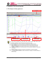
1
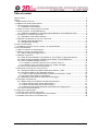
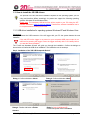
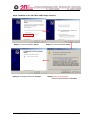
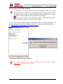
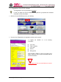
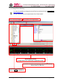
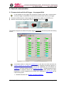
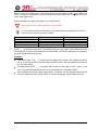
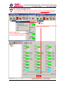
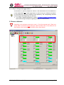
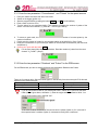
% km/h 225 rpm 175 125 100 75 1:42.60 25 0 0 0 2500 50 25 5000 7500 50 150 75 10000 200 100 12500 Start 3:52.5 3:55.0 3:57.5 4:00.0 Art.No.: AC-DOC_SY-KIT-Software_08-000 4:02.5 4:05.0 4:07.5 4:10.0 t modified 08.10.2009 Table of content Table of content ................................................................................................................................................. 2 Preface .............................................................................................................................................................. 3 SYMBOLS USED IN THE TEXT ................................................................................................................ 3 1. Installation of the 2D Kit system software ........................................................................................................ 4 1.1 FIRST STEPS IN THE SOFTWARE...................................................................................................... 4 1.1.1 Installation of the software ................................................................................................... 4 1.2 HOW TO UPDATE THE SOFTWARE VIA INTERNET ............................................................................... 5 1.3. HOW TO INSTALL THE 2D USB DRIVERS ......................................................................................... 6 1.3.1 USB driver installation for operating systems Windows XP and Windows Vista .................... 6 1.4 LICENSING OF THE 2D KIT SOFTWARE............................................................................................. 8 1.4.1 Registration of the 2D Kit software ....................................................................................... 9 1.5 GENERAL INFORMATION ON THE DATA STRUCTURE ......................................................................... 10 1.5.1 Create a new Event directory ............................................................................................. 11 1.5.2 Change Event directory ..................................................................................................... 12 2. Check of communication .............................................................................................................................. 13 2.1 COMMUNICATION WITH THE KIT LOGGER - THE PROGRAM W INIT ...................................................... 13 3. How to download data .................................................................................................................................. 14 3.1 HOW TO PREPARE THE MEASUREMENT .......................................................................................... 14 3.2 HOW TO CHANGE THE LOGGER NAME ? ......................................................................................... 16 3.2.1 Why to change the logger name ?...................................................................................... 17 3.3 SENSOR CALIBRATION ................................................................................................................. 17 3.3.1 Enter the two parameters "Circumference" and "Pulses" for the speed sensors ................. 18 3.3.2 Enter the two parameters "Rotations" and "Pulses" for the RPM sensor ............................. 18 3.3.3 How to calibrate analogue sensors ?.................................................................................. 19 3.3.3.1 Calibration of the Rear suspension sensor (channel “Susp_R“) ................................................... 20 3.3.3.2 Calibration of any other analogue sensor e.g. Throttle, Trim angle,.. ........................................... 21 3.3.4 How to set a channel into Zero position ? ........................................................................... 21 3.4 USING AND CHECKING THE TABLE FUNCTION .................................................................................. 22 3.4.1 Change the table for the Motor temperature channel “T_Mot“ ............................................. 22 3.4.2 Change the table for GPS laptrigger positions .................................................................... 24 3.4.2.1 How to create self defined GPS line coordinates and store them in a table .................................. 24 4.2.2 GPS line Internet Update from 2D Website ................................................................................... 25 3.4.3 Update the “track positions” table into the Kit-Logger.......................................................... 26 3.5 STARTING THE DOWNLOAD .......................................................................................................... 27 3.5.1 What to keep in mind before start with the download ? ....................................................... 27 3.5.1.2 When does the system start the data recording ? ....................................................................... 27 3.5.1.3 When does the system stop the data recording ? ....................................................................... 27 3.5.1.4 What should be avoided while WinIt communicates with a logging device ................................... 27 3.5.2 How to start a download ?.................................................................................................. 28 4. Analysis of the measuring data ..................................................................................................................... 29 4.1 THE ANALYZER DESKTOP APPEARANCE ......................................................................................... 29 4.2 THE INDIVIDUAL ANALYSIS WINDOWS AND THEIR MEANING ............................................................... 30 4.3 COMMON FUNCTIONS OF THE 2D ANALYZER .................................................................................. 30 AC-DOC_SY-KIT-Software_08-000 page 2 / 30 Preface This documentation contains the necessary information to setup and to work with the 2D kit system. In order to achieve the optimum result when working with the 2D-Kit System, we recommend to read the instructions carefully and follow them step by step. Symbols used in the text In the paragraphs highlighted with this symbol, you will find tips and practical advice to work with the 2D-Kit System. In the paragraphs highlighted with this symbol, you will find additional information and it is very important that you follow the instructions given. Documentation reference The user get an unique item number for an user manual to find further assistance Additional information about manuals, datasheets, software updates or new calculation files can be downloaded from our homepage. The specific download area for the Kit system can be found at: http://www.2d-kit-system.com (=>See Downloads) 2D Debus & Diebold Meßsysteme GmbH Alte Karlsruher Straße 8 76227 Karlsruhe Tel.: +49(0)721 94485-0 Fax: +49(0)721 94485-29 EMAIL: [email protected] Homepage: http://www.2D-Datarecording.com Homepage: http://www.2D-Kit-System.com AC-DOC_SY-KIT-Software_08-000 page 3 / 30 1. Installation of the 2D Kit system software 1.1 First steps in the software 1.1.1 Installation of the software Before starting the installation of the 2D Kit software please assure that you have administrator rights on this computer. This applies to Windows XP and Windows Vista. Otherwise the USB driver files cannot be installed correctly, since these must be installed with administrator rights! 1. Insert the 2D-CD. The installation process will start automatically. If this is not the case, start the "AUTORUN.EXE" on the CD manually. 2. Select the button Install RaceKit9.x (on the lower panel) 3. Choose the software version for your application 4. A set-up wizard guides you through the installation. Follow the instructions and confirm your actions (in most cases with Apply). If necessary, also enter the setup directory. All required files including demo data will be installed automatically. These can befound on the same drive that your operating system is installed on, at"..\Racedata\Demodata\". I. e. if your operating system is installed on drive C:, then your your demo files will be stored at "C:\Racedata\Demodata\". AC-DOC_SY-KIT-Software_08-000 page 4 / 30 1.2 How to update the software via Internet 1. Start WinARace 2. Select menu item Help\ <Search for software updates> 3. The “2D Internet Update Wizard” offers a list of possible files for update. Check all boxes from the list you want to update. 4. Confirm your selection with the button Update AC-DOC_SY-KIT-Software_08-000 page 5 / 30 1.3. How to install the 2D USB drivers The process of the 2D USB driver installation depends on the operating system you are using and therefore differs accordingly. At present we support the following operating systems: Windows XP and Windows Vista. Please note: The necessary USB driver files will be copied to your PC during the KITsoftware installation (refer to previous chapter) Therefore the software installation has to be completed before installing the drivers! 1.3.1 USB driver installation for operating systems Windows XP and Windows Vista Preparation: After you connect the USB connector of the Kit logger with your PC the system detects the new hardware. If the red LED on the logger is not turned on your computers USB power output is not sufficient for powering the logger. Power the logger externally with a 12V battery before you start the driver installation The “Found new Hardware Wizard” will guide you through the installation. Confirm the dialogs as shown below to finalize the USB driver installation. The installation runs in two steps. Step1: Installation of the "2D USB Composite Device" Dialog 1: Confirm with button <Next> Dialog 4: Finalize with button <Finish> Dialog 2: Confirm with button <Next> Dialog 3: Only for Windows XP ! Confirm always with button <Continue Anyway> AC-DOC_SY-KIT-Software_08-000 page 6 / 30 Step2: Installation of the "2D USB to UART Bridge Controller" Dialog 1: Confirm with button <Next> Dialog 4: Accomplish with button <Finish> Dialog 2: Confirm with button <Next> Dialog 3: Only for Windows XP ! Confirm always with button <Continue Anyway> AC-DOC_SY-KIT-Software_08-000 page 7 / 30 1.4 Licensing of the 2D Kit software The licensing of the 2D-Kit software takes place automatically. Start the Front-end WinARace (icon at your desktop). Your Kit-logger must be online (means: voltage supply of the system must be ensured). Connect the USB cable with a free USB port at your PC. Afterwards connect the USB cable with the connector at the Kit logger. Take a look at chapter3 of the “KIT Basic system 2D” manual (=AC-DOC_SY-KITBasic_08-000) to get a connection diagram of the KIT logger. The "2D USB checker software" (started with WinARace) scans all available COM ports for a connected Kit logger (left figure). Afterwards you have the chance to register the 2D Kit software. Refer to next chapter (“Registration of the 2D KIT software”) USB checker: Scanning for 2D Kit hardware The program recognizes and stores the licensing data of the connected logger automatically and prompts about the process AC-DOC_SY-KIT-Software_08-000 page 8 / 30 1.4.1 Registration of the 2D Kit software The Registration of the 2D kit software is voluntary ! In case you register the 2D Kit software you are justified to get updates and newsletter information for your Kit software. Start the front-end WinARace (Icon at your desktop). Via menu item <Registration> the registration window can be opened To register the software fill in the following information: Your name Team / company Your email FAX No. Racing series Use the button <Email> to send us an email or the button <Print Fax to 2D> to get a fax template with all relevant information. Please make sure that your email address is entered correctly ! AC-DOC_SY-KIT-Software_08-000 page 9 / 30 1.5 General information on the data structure WinARace, the front-end program started on the desktop, shows the following three levels: a.) Event-/ measurement administration b.) Logger communication/ Measurement naming (preparation) c.) Measurement selection & analysis The program WinIt creates one sub-directories entry for each measurement in the current Event directory during the download. All measurement files have got the extension *.MES The name given to the measurement is a combination of the current logger name => Refer to chapter ”3.1 How to prepare the measurement“ The directory structure of your computer with your measured data should look like this example: Data directory } Event directories Measurement (*.MES directory) The first and most important step before downloading the first measurement is to create a “Event”- Always start with this step, so that you always know where your data are saved ! AC-DOC_SY-KIT-Software_08-000 page 10 / 30 1.5.1 Create a new Event directory Switch to the "Event-module" by clicking on the button Change Event. The current directory is shown on the left hand side. It defines where data will be saved or from where measurements are read. Create Event will set up a new directory with the option to select the track used at that event. This step should be always the first before staring a “race-weekend” Always start with this step, so that you always know where your data are saved ! To create new Event directories use the button Create Event in the front-end tool WinARace. The following window will appear. Select a circuit from the list on the right hand side. The name of the selected track combined with the current date will become the default name of the Event. For example . This Event was produced at 30.06.2009 in Calafat) To change the name to your preferences edit the field Eventname. Confirm your selection with the button OK. There are two different circuit sub-directories: 1. The sub-directory “\Circuits“: Includes a list of pre-defined tracks delivered with the 2D Race software. 2. The sub-directory "\MyCircuits": Contains track maps which have been created by the user via the Analysis tool. If a track is not listed select <Click here if circuit is not in list> and a basic circuit will be selected (Base.ren). Rename the Eventname according to the track that the data are from AC-DOC_SY-KIT-Software_08-000 page 11 / 30 1.5.2 Change Event directory You have the possibility to change the current Event by selecting the button Change Event refer to chapter 1.1.5 The figure below shows you the start-window of the “Event-module” Event selecting/changing Measurement selecting/changing Quick analysis overview Change channel via context menu (=right mouse click) SpecSheet information (belonging to each 2D measurement) Better known as “HED files” Direct access to Analysis tool (same as key F3 in WinARace) AC-DOC_SY-KIT-Software_08-000 page 12 / 30 2. Check of communication 2.1 Communication with the Kit logger - the program WinIt In this dialogue box the Logger and computer are linked to each other. Communication with the Kit-logger is established to download the measured data and set up the logger. Connect the USB connector of the kit logger with the computer. (Make sure red LED is on) Start the communication program WinIt (click on Logger or hit the hot key F2 ) The software recognizes an attached Kit system-logger automatically and comes up with the following window. This window allows to modify the circumference of rear and front wheel and also the number of pulses for one wheel turn. Be aware that changing the gearing (sprocket or plate) will change the number of pulses at the rear. Additionally you can calibrate the suspension and other analogue sensors (throttle, trim angle ). The brake pressure sensor and the front suspension sensor can only be set to zero. Other sensors like water temperature or motor temperature do not have to be calibrated. A table function will be used for this purpose. Detailed information are in chapter “3.2 Sensor calibration” AC-DOC_SY-KIT-Software_08-000 page 13 / 30 3. How to download data 3.1 How to prepare the measurement Before each run (or download) you should check the name that will be given to the measurement. Take care choosing the name to assure which measurement relates to which driver and outing. It is a lot easier for you then to work with the measurements later. The measurement name is a combination of the current mastername (type of test) and the logger name. The mastername is specified from WinARace (Icon at your desktop) and the actual logger name you specified in the communication tool WinIt 1. Switch to the WinARace start window. 2. On the left side of the Logger-panel select an abbreviation from the drop-down list. This is the mastername or type of test. Possible masternames RUN(Initial value, first mastername after first installation) DATE-___(current date information, see detailed information) Test-___(Test) F1-___(Free Practice) F2-___(Free Practice) Q1-___(Qualifying) Q2-___(Qualifying) WU-___(WarmUp) R1-___(Race) R2-___(Race) AC-DOC_SY-KIT-Software_08-000 page 14 / 30 Devices, which record data, have a name that might be either the starting number or the initials of the driver. If a logger is connected for the first time with the communication tool, it prompts the user to enter a valid logger name. Define the name of the logger accordingly to your requirements. We suggest the use of starting numbers of your vehicles. In a new measurement the underscores of the masternames are replaced by the name of the device and a correlative number is added. Device name Starting numbers: Replacement (underscores) NNc Driver intitials: BBc Possible values N possible values 0..9 c possible values a..f B possible values A..Z c possible values a..f "DATE-___-" is a special mastername. The software replaces the part "Date" of the mastername by the month and day on which the measurement was downloaded. The first two characters are replaced by the month and the next two by the day. Examples: If the master name "Test-___-" is selected and the logger has the name “22a” (Starting number 22 and “a“ for the first vehicle of two drivers with the same number), the first measurement name will be "Test-22a-01.MES". The mastername "DATE-___-" is selected and the name of the logger is “MH”. Today it is the 14.04. The resulting measurement name for the first download is "0414-MH-01.MES". After installation the default master name "RUN-" is selected. The first download would receive thus the measurement name "Run-01.MES", the second accordingly "Run-02.MES" and so on. AC-DOC_SY-KIT-Software_08-000 page 15 / 30 3.2 How to change the logger name ? You can change the logger name by direct selection + input or via the context menu (using right mouse click on selected logger node). The name may not exceed 8 characters. These cannot be stored into the logger setting and are cut off accordingly ! Enter a new logger name (e.g. for example the Start number of your vehicle. Select the logger node + enter the context menu (right mouse click) + choose „Rename“ from the menu Apply all changes with the button <Apply> AC-DOC_SY-KIT-Software_08-000 page 16 / 30 3.2.1 Why to change the logger name ? As described in a previous chapter the name of a 2D measurement is the combination of current mastername and current logger name. In case of using an “underscore character” in the mastername (“_”), this character will be replaced by the corresponding character from the logger name (beginning from the end) You will get a detailed explanation in chapter ”3.1 How to prepare the measurement“ and some meaningful examples regarding naming your measurements. 3.3 Sensor calibration Depending on the software version that is used V_Front (front speed) and V_Rear (rear speed) wheel circumference and pulses per wheel revolution have to be entered in the start window of the communication tool WinIt (refer to figure below). AC-DOC_SY-KIT-Software_08-000 page 17 / 30 3.3.1 Enter the two parameters "Circumference" and "Pulses" for the speed sensors 1. 2. 3. 4. 5. Park your vehicle so that the rear wheel can rotate. Switch on the logger (ignition on). Start the program WinIt by pressing the button Logger or hit F2 (from WinARace) Place a mark on the tire or rim. Turn the wheel for one complete rotation. The software will display the number of pulses of the sensor in an own count channel ("V_RearCNT" - refer to figure below) 6. To ensure a good result, do several rotations and divide the number of counted pulses by the number of rotations. 7. Finally enter the number of pulses for one complete rotation in the edit field V_Rear, Pulses. 8. Enter the circumference of your motorcycle wheels in the edit field Circumference (rear and front are different !). 9. Confirm your inputs with the button Apply For the front wheel follow the same procedure. Read the number of pulses from the count channel "V_FroCNT". (Step 5) 3.3.2 Enter the two parameters "Rotations" and "Pulses" for the RPM sensor For the RPM sensor you have to enter the following two parameters: Rotations and Pulses. There are 3 common ratios. Since the RPM signal is used directly from the motorcycle ECU this ratio depends on the used motorcycle. Option 1 Option 2 Option 3 Rotations = 1 Rotations = 2 Rotations = 1 Pulses = 1 Pulses = 1 Pulses = 2 If you do not know this ratio for your motorcycle enter 1 rotation and 1 pulse into the RPM fields (refer to figure above, alternative 1). Start the engine while connected to WinIt. You will see current motor revs in the field “rpm”. If the value is about the double of the real one enter 2 pulses (Option 3). If it is the half of the expected enter 2 rotations (Option 2). Instruments usually have a tolerance ! AC-DOC_SY-KIT-Software_08-000 page 18 / 30 3.3.3 How to calibrate analogue sensors ? WinIt offers two ways to calibrate sensors: You can enter the lower and upper physical value of the sensor manually. Therefore an appropriate data sheet of the sensor is necessary as you need to know the possible physical range in reference to the voltage signal output. You have to enter two voltage- or digit- values to calibrate the sensor. Therefore use the button : Rule of Three Manually The second way is using the automatic determination of the two mentioned limits. The function will start the sampling of the channel to find the minimum and maximum value for this channel. After the sampling the rule of three dialog opens and you have to enter the corresponding physical values for the sampled minimum and maximum. Therfore use the Button: Rule of Three Automatically We recommend to use automatic calibration, because this represents the easiest and fastest possibility to calibrate a sensor. AC-DOC_SY-KIT-Software_08-000 page 19 / 30 3.3.3.1 Calibration of the Rear suspension sensor (channel “Susp_R“) 1. 2. 3. 4. 5. 6. 7. 8. Switch on the logger (ignition on). Start the program WinIt by pressing the button LOGGER or hit F2 (from WinARace) Use the button Calibrate (in the WinIt start window) of the sensor you would like to calibrate. Click the button Rule of Three Automatically =>Step1 Adjust the sensor in MINIMUM position and hit Refresh Minimum => Step2 | Step3 Adjust the sensor in MAXIMUM position and hit Refresh Maximum => Step2 | Step4 Use the Button OK to enter the “Rule of three dialog” => Step2 In the example shown below a 75mm suspension sensor was used. Accordingly you should enter 0mm for the “lower physical value” and 75mm for the “upper physical value” => Step5 Step1 Step2 Step4 Step3 Step5 To measure suspension stroke the sensor has to be mounted parallel to the damper. If it is mounted at another position the actual spring travel must be measured before entering the values as the damper will have a different travel as the sensor. AC-DOC_SY-KIT-Software_08-000 page 20 / 30 3.3.3.2 Calibration of any other analogue sensor e.g. Throttle, Trim angle,.. The calibration of other analogue sensors is the same as described in the chapter before. Just the input of the physical values in the rule of three dialogue (step 5) has to be accordingly to your sensors measurement. Throttle (0%-100%), Trim Angle( 0°- x°) with x being whatever the movement or maximum measuring point is. 3.3.4 How to set a channel into Zero position ? Heat or other factors that change the geometry of suspensions can cause some of the sensors to drift or to have a different zero position. In these cases it is not necessary to calibrate the sensors again! Instead you can use the function "Zero". According to the preceding chapter you can choose between "Set Zero Manually " and an "Automatic Zero"function. You can start both functions via the Zero button. <Set Zero Automatically> function: Clicking this button will start the sampling of the channel to find the zero position. Bring the sensor into it’s zero position and press Sample average <Manually> function Clicking this button will take the current value of the channel to set the value to zero. In bike systems it is possible to set both suspension and throttle sensor zero in one step. With this button (from the WinIt toolbar) you can send the auto-zero command to the logger. AC-DOC_SY-KIT-Software_08-000 page 21 / 30 3.4 Using and checking the table function Some sensors, like water or oil temperature sensors, cannot be calibrated manually, because of the nonlinear output signal of the sensor. To obtain fitting measurement results you have to use the table function of the KIT software. 3.4.1 Change the table for the Motor temperature channel “T_Mot“ As can be seen in the starting window of the KIT software the current table name is identical to the channel name (=”T_MOT”). Different vehicles (like Kawasaki, Suzuki, Yamaha and so on) need different temperature table to calibrate the channel “T_Mot”. To change the table of the “T_Mot” channel, carry out the following steps: 1. Start WinIt in Setting mode (Press button Logger (F2) from WinARace or hit hot key <F2>) 2. Select tab “Send tables” 3. 4. Choose Button Send temperature table (T_Mot) 5. Select your vehicle from the list and confirm with button Ok If your vehicle is not in the list please contact the 2D support or one of the distributors. AC-DOC_SY-KIT-Software_08-000 page 22 / 30 6. The last step is the user confirmation to store the new table in the logger. Confirm this dialogue with Yes to update your KIT system with the selected (new) table. AC-DOC_SY-KIT-Software_08-000 page 23 / 30 3.4.2 Change the table for GPS laptrigger positions Similar to the function in the previous chapter it is possible to update the tables for the GPS laptrigger (positions + names). There are 2 sources for new GPS laptrigger tables: a.) Self defined GPS line coordinates (via analysis tool “Analyzer” refer to chapter 3.4.2.1) b.) Internet update from 2D Website (refer to chapter 4.2.2 ) 3.4.2.1 How to create self defined GPS line coordinates and store them in a table Some 2D Kits create their laptimes via GPS. The logger has a table of GPS start line positions that trigger the laptime creation. If no laptimes are available in a GPS measurement a GPS laptrigger can be created and the position table in the logger be updated for automatic creation of the laptimes. 1. Use a left mouse click to choose the position of your GPS laptrigger location in the measurement. Open the menu shown in the picture below and select <Set GPS start line>. 2. Save the line with the name of the track the data are measured. AC-DOC_SY-KIT-Software_08-000 page 24 / 30 3. Confirm that the laps will be created with this line file 4. Open up the menu again by right mouse click and choose <Store GPS line coordinates in GPS lap table> 4.2.2 GPS line Internet Update from 2D Website 1. Start WinARace 2. Select menu item “Search for software updates” 3. The “2D Internet Update Wizard” offers you a list of possible files for update. Check table “ 2dtrkpos.tbl” and “ 2dtrknme.tbl” from list. 4. Confirm your selection with the button Update AC-DOC_SY-KIT-Software_08-000 page 25 / 30 3.4.3 Update the “track positions” table into the Kit-Logger After creating a new GPS line in Anna-Liza or download of a new GPS line table “2dtrkpos.tbl” (via 2D Internet update refer to chapter 4.2.2 ) it is necessary to store this table into the Kit-logger. Start WinIt in Setting mode (Press button Logger (F2) from WinARace or hit hot key <F2>) Select tab “Send tables” and choose button Send laptrigger position table (2dtrkpos.tbl) After this step your GPS laptriggers are up to date. AC-DOC_SY-KIT-Software_08-000 page 26 / 30 3.5 Starting the download 3.5.1 What to keep in mind before start with the download ? 3.5.1.2 When does the system start the data recording ? The data recording begins only if the rpm sensor was correctly connected (it means that the rpm sensor supplies a signal) and the RPM signal is higher than 3000 [rpm]. 3.5.1.3 When does the system stop the data recording ? The recording stops immediately if power supply is switched off. In most vehicles if ignition is switched off. 3.5.1.4 What should be avoided while WinIt communicates with a logging device Never disconnect the USB cable while WinIt communicates with the Kit logger (. That can cause a crash of the USB driver. In this case a communication would be no longer possible via the current USB port. Then a restart of your computer will be necessary. Therefore always wait for the completion of a download. Close the communication software WinIt (via <ALT+ F4> or <ALT+X>) and disconnect the USB communication cable afterwards ! AC-DOC_SY-KIT-Software_08-000 page 27 / 30 3.5.2 How to start a download ? There are two ways to start a download. “Download” means to transfer the measurement data from a connected KIT Logger into the PC. The first way is to start the download operation manually. Start the front-end tool WinARace, connect the USB cable to the logger. Select the Button Quick download (F9) to start the download operation You can also perform the download automatically every time a 2D USB device is detected. This option can be set in WinIt. This is the standard pre-setting after the first software installation. To start the download always automatically do not uncheck this option ! AC-DOC_SY-KIT-Software_08-000 page 28 / 30 4. Analysis of the measuring data 4.1 The Analyzer desktop appearance Toolbar Overview window Moving window Circuit window You can start all functions from the main menu, context menus (right mouse click). The toolbar is divided into the following functions (from left to right) File functions are functions to load and exchange 2D measurement files Basic analysis functions include Moving and Overview windows and lap times Advanced analysis functions include Track mode, XY-Plot and Min/max table Visibility of channels in the Moving window can be switched separately or by groups or via areas Another function accessible via toolbar is the selection of a screen template. The measurement functions include commands to display the measurement(s) in different ways AC-DOC_SY-KIT-Software_08-000 page 29 / 30 4.2 The individual analysis windows and their meaning Overview window The Overview window is located at the bottom of the screen. Selected channel traces and lap time information are shown. The rectangle in the Overview window marks the position of the selection that can be seen in the Moving window. You can move the rectangle by pressing the left mouse button and moving the mouse. If you press the <Ctrl> key simultaneously you can change the size of the rectangle. Moving window The Moving window is the main analysing window where the channel traces of the selected part of the measurement is shown. The section of the measurement can be moved by pressing the left mouse button and moving the mouse. With a double click on the Moving window you change into the Measuring mode (see measuring mode). Mouse pressed + move up/down => Zoom Circuit window The Circuit window is the small window in the right bottom corner of your screen. The window shows the track map with the current section of the active measurement highlighted. Multi circuit window GPS driving line of all loaded measurements are shown in this window. In Measuring mode the position(s) of the mouse cross inside Moving window is drawn here. It makes especially sense showing several measurements with GPS recorded to highlight different driving lines. Measuring mode You can change into the Measuring mode with a double click in the Moving window. A measuring cross and another window (Measuring values) appear. In the value window the physical values of the traces are shown, dependent on the current position of the mouse. 4.3 Common functions of the 2D Analyzer As previously mentioned it is possible to register the Kit-software. refer to chapter 1.3.4 “Registration of the 2D Kit software” An advantage is that you are entitled to receive additional analysis settings on request. Take a look on the KIT System website (www.2d-kit-system.com). There you will find a table with standard settings (=unregistered KIT software) and additional analysis settings (=registered KIT software) Please contact your KIT system distributor or the Kit-System support if you need other settings. In order to be able to get other Settings you must be a registered KIT user. Refer to chapter “Registration of the KIT software” AC-DOC_SY-KIT-Software_08-000 page 30 / 30


![[1]StorageTek Linear Tape File System, Open Edition](http://vs1.manualzilla.com/store/data/005641506_1-83def2383162ce3771fdbc891794971f-150x150.png)