1
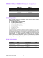
User Manual ASMB-310IR/310 Dual 1366 Socket CEB Server Board with 2 PCIe x16 Expansion Slots Copyright The documentation and the software included with this product are copyright 2011 by Advantech Co., Ltd. All rights are reserved. Advantech Co., Ltd. reserves the right to make improvements in the products described in this manual at any time without notice. No part of this manual may be reproduced, copied, translated or transmitted in any form or by any means without the prior written permission of Advantech Co., Ltd. Information provided in this manual is intended to be accurate and reliable. However, Advantech Co., Ltd. assumes no responsibility for its use, nor for any infringements of the rights of third parties, which may result from its use. Acknowledgements Intel and Pentium are trademarks of Intel Corporation. Microsoft Windows and MS-DOS are registered trademarks of Microsoft Corp. All other product names or trademarks are properties of their respective owners. ASMB-310IR/310 User Manual Part No. 2006310R01 Edition 2 Printed in Taiwan September 2011 ii Peripheral Compatibility Order Information Processor P/N Description Manufacturer PN 96MPXE-2.53-8M13T XEON 2.53G 8M 1366P 4CORE E5540(G) AT80602000789AA (E5540/ SLBF6) - Quad Core - Embedded 96MPXE-2.0-4M13T XEON 2.0G 4M 1366P 4CORE E5504(G) AT80602000801AA (E5504/ SLBF9) - Quad Core - Embedded 96MPXE-2.4-12M13T XEON 2.4G 12M 1366P 4CORE E5620(G) AT80614005073AB (E5620/ SLBV4) 96MPXE-2.13-8M13T XEON 2.13G 8M 1366P 4CORE L5518(G) AT80602002265AB (L5518/ SLBFW) 96MPXE-2-8M13T XEON 2.0G 8M 1366P 2CORE L5508(G) AT80602002697AC (L5508) 96MPXE-2.4-12M13T1 XEON 2.4G 12M 1366P 6CORE E5645(G) AT80614003597AC (E5645/ SLBWZ) Memory P/N Description Manufacturer PN 96D3-1G1333E-AP 1G DDR3-1333 240PIN ECC 128X8 ELP(G) 78.01GC8.422 96D3-2G1333E-AP 2G DDR3-1333 240PIN ECC 128X8 ELP(G) 78.A1GC8.423 96D3-4G1333E-AP 4G DDR3-1333 240PIN ECC 256X8 HYX(G) 78.B1GDF.AF3 96D3-1G1333ER-AP 1G DDR3-1333 240PIN REG 128X8 ELP(G) 78.01GCC.420 96D3-2G1333ER-AP 2G DDR3-1333 240PIN REG 128X8 ELP(G) 78.A1GCC.421 96D3-4G1333ER-AP1 4G DDR3-1333 240PIN REG 256X8 HYX(G) 78.B1GDM.AF1 SATA HDD P/N Description Manufacturer PN 96HD500G-ST-SG7K6 SEAGATE 500G 3.5" SATA 7KRPM 16M(G) ST3500418AS 96HD1000G-ST-SG7K SEAGATE 1000G 3.5" SATA 7KRPM 32M(G) ST31000528AS SAS HDD P/N Description Manufacturer PN 96HD146G-SS-SG15K1 Seagate 3.5" SAS 15K 146G, dual ports ST3146356SS iii ASMB-310IR/310 User Manual ASMB-310IR and ASMB-310 Feature Comparison ASMB-310IR ASMB-310 Chipset E5520 E5520 SAS 8 n/a SATA 6 6 PCIe 4 x PCIe x8 (or 2 x PCIe x16), 1 x PCIe x4 4 x PCIe x8 (or 2 x PCIe x16), 2 x PCIe x4 IPMI IPMI 2.0 + iKVM n/a LAN(RJ-45) 3 2 S/W RAID yes yes Initial Inspection Before you begin installing your motherboard, please make sure that the following materials have been shipped: 1 x ASMB-310IR/310 CEB motherboard 1 x ASMB-310IR Startup Manual 1 x Driver CD (user's manual is included) 2 x Serial ATA HDD data cables 2 x LGA 1366 2U/4U CPU Cooler 1 x I/O port bracket 2 x SATA power cable 1 x Warranty card If any of these items are missing or damaged, contact your distributor or sales representative immediately. We have carefully inspected the ASMB-310IR mechanically and electrically before shipment. It should be free of marks and scratches and in perfect working order upon receipt. As you unpack the ASMB-310IR, check it for signs of shipping damage. (For example, damaged box, scratches, dents, etc.) If it is damaged or it fails to meet the specifications, notify our service department or your local sales representative immediately. Also notify the carrier. Retain the shipping carton and packing material for inspection by the carrier. After inspection, we will make arrangements to repair or replace the unit. Order Information Part Number HDD Expansion Slot ASMB-310-00A1E 6 SATA 4 x PCIe x8 (or 2 x PCIe x16), 2 x PCIe x4 ASMB-310IR-00A1E 6 SATA + 8 SAS/SATA 4 x PCIe x8 (or 2 x PCIe x16), Yes 1 x PCIe x4 ASMB-310IR/310 User Manual iv IPMI Contents Chapter 1 Overview...............................................1 1.1 1.2 1.5 1.6 1.7 1.8 Introduction ............................................................................................... 2 Features .................................................................................................... 3 1.2.1 General ......................................................................................... 3 Specifications ............................................................................................ 4 Table 1.1: Specification ............................................................... 4 Board Layout, Jumpers and Connectors................................................... 6 Figure 1.1 Board layout ............................................................... 6 Figure 1.2 Rear I/O ...................................................................... 7 Table 1.2: Onboard LAN LED Color Definition ............................ 7 Table 1.3: Jumpers...................................................................... 7 Table 1.4: Connectors ................................................................. 7 Table 1.5: Onboard LED............................................................. 8 Block Diagram........................................................................................... 9 System Memory ...................................................................................... 10 Memory Installation Procedures.............................................................. 10 Processor Installation.............................................................................. 10 2 Connections .......................................11 2.1 2.2 2.3 2.4 2.5 2.6 2.7 2.8 2.9 2.10 2.11 2.12 2.13 2.14 2.15 2.16 2.17 2.18 Introduction ............................................................................................. 12 USB Ports and LAN Ports (USB01/USB23/USB45/LAN1/LAN2/ IPMI_LAN1)............................................................................................. 12 VGA Connector ....................................................................................... 13 Serial Ports (COM1/COM2) .................................................................... 14 PS2 Keyboard and Mouse Connectors (KB1MS) ................................... 15 CPU Fan Connector (CPU FAN0/CPU FAN1)........................................ 16 System FAN Connector (SYS DFAN1/UFAN1/RFAN1) ......................... 17 Front Panel Connector (FPPH1) ............................................................. 18 SGPIO (SGPIOA1/SGPIOB1)................................................................. 19 Front Panel LAN Indicator Connector (LANLED1).................................. 20 Serial ATA Interface (SATA0 ~ 5) ........................................................... 21 PCIe x16 Expansion Slot (PCIEX16_1/PCIEX16_3) .............................. 22 PCIe x4 Expansion Slot (PCIEX4_5/PCIEX4_6) .................................... 23 PCIe x8 Expansion Slot (PCIEX8_2/PCIEX8_4) .................................... 24 Series Attached SCSI Interface (SAS0 ~ 7)............................................ 25 Auxiliary Power Connector (ATX_8P_PQ/ATX_8P_P1/ATX_P24)......... 26 HD Audio Interface Connector (HDAUD1) .............................................. 27 LPU connector (LPU2) ............................................................................ 28 3 AMI BIOS ............................................29 3.1 3.2 Introduction ............................................................................................. 30 BIOS Setup ............................................................................................. 31 3.2.1 Main Menu .................................................................................. 31 3.2.2 Advanced BIOS Features Setup................................................. 32 3.2.3 Advanced PCI/PnP Settings ....................................................... 36 3.2.4 Boot Settings............................................................................... 37 3.2.5 Security Setting........................................................................... 39 3.2.6 Advanced Chipset Settings......................................................... 39 3.2.7 Exit Option .................................................................................. 41 1.3 1.4 Chapter Chapter v ASMB-310IR/310 User Manual ASMB-310IR/310 User Manual vi Chapter 1 Overview 1 1.1 Introduction ASMB-310IR serverboard is the most advanced Intel E5520 board for industrial server applications that require high-performance computing. The serverboard supports Intel Xeon 5500/5600 processors and DDR3 800/1066/1333 MHz memory up to 48GB. ASMB-310IR provides dual PCIe x16 slots which support two high performance graphic cards. In addition, the ASMB-310IR has dual Gigabit Ethernet LAN ports via a dedicated PCIe x1 bus, which offers bandwidth of up to 500 MB/s, eliminating network bottlenecks. High reliability and outstanding performance make the ASMB-310IR the ideal platform for industrial server/networking applications. By using the Intel E5520 chipset, the ASMB-310IR offers five PCIe slots; two PCIe x16 slots, two PCIe x8 slots, one PCIe x4 slot and a variety of features such as 6 onboard SATA II interfaces (bandwidth = 300 MB/s) with software for RAID 0, 1, 10 and 5 (Windows only); 11 USB 2.0 connectors. Furthermore, ASMB-310IR is embedded with an LSI SAS controller 1068E, and can support 8 SAS/SATA HDD with software RAID 0, 1, 1E. These powerful I/O capabilities ensure even more reliable data storage capabilities and high-speed I/O peripheral connectivity. With all these excellent features and outstanding performance, the ASMB-310IR is the ideal platform for today's industrial server applications. Note! ASMB-310 SKU contains 6 PCIe slots; two PCIe x16 slots, two PCIe x8 slots, and two PCIe x4 slots. ASMB-310 does not have an SAS controller onboard. ASMB-310IR/310 User Manual 2 1.2.1 General 3 ASMB-310IR/310 User Manual Overview PCIe architecture: The Intel E5520 PCH chipset supports 36 PCIe lanes. Intel latest Daul processor platform: ASMB-310IR support two Intel Latest 5500/5600 Quad/Dual core Processor. High performance I/O capability: Dual Gigabit LAN via PCIe x1 bus, one PCIe x4 slot, 6 SATAII connectors and 11 USB 2.0 ports and 8 SAS/SATA connectors (ASMB-310IR only) Standard CEB form factor with industrial features: ASMB-310IR provides industrial features like long product life, reliable operation under wide temperature range, watchdog timer, etc. SAS hard drive support: Embedded LSI 1068E SAS controller which can support eight SAS/SATA HDD with software RAID 0,1,1E. IPMI 2.0 support: ASMB-310IR equip Aspeed 2050 BMC chip supports IPMI 2.0 (Intelligent Platform Management Interface 2.0) via dedicated LAN port. KVM over IP: ASMB-310IR KVM over IP function. Chapter 1 1.2 Features 1.3 Specifications Table 1.1: Specification Processor CPU Processor Bus Dual 1366-pin LGA Sockets Intel® 64-bit Xeon® processor(s) Quad-Core Intel® Xeon® Processor 5500 / 5600 sequence (Nehalem-EP/ Westmere processor) Support TDP 60W/80W/95W CPU QPI bus speed as 6.4 GT/s System Memory Memory Capacity Xeon processor support DDR3 memory bus Each processor have 3 channels memory bus, each channel have one DIMM socket. 3 x 240-pin DIMM sockets for each processor, total 6 x DIMM sockets Support up to 48 GB memory Memory Type Support 1333 / 1066 MHz ECC Registered / Unbuffered ECC DDR3 modules DIMM Sizes Each memory socket support 1 GB, 2 GB, 4 GB, 8 GB memory size module. Memory Voltage 1.5 V Error Detection Corrects single-bit errors Detects double-bit errors (using ECC memory) Supports Intel® x4 and x8 Single Device Data Correction (SDDC) Intel 5520 ( Tylersburg 36D) chipset IOH ICH10R chipset Intel 5520 IOH provide 36 lanes PCIe Gen-2 bus, used for PCIe slots. ICH10R provide SATA, USB, Network, motherboard basic I/Os SAS LSI1068E (ASMB-310IR SKU Only) conntected to ICH10R PCI-e Gen1 x4 lanes On-Board Devices Chipsets Network Controllers 1x Intel 82574L Gigabit Ethernet Controller connected to ICH10R PCIe-Gen-1 Lane 1x Intel 82567LM Gigabit PHY connected to ICH10R MAC Above network Supports 10BASE-T, 100BASE-TX, and 1000BASE-T, RJ45 output 1x 10/100BASET RTL8201N PHY(Realtek) connected to AST2050 dedicated IPMI/IKVM, if this option is on VGA ASPEED AST2050 controller with 64 MB VGA memory provides basic 2D VGA function Super I/O Winbond W83627DHG chip provide motherboard keyboard mouse, RS232, and Hardware monitor functions. SAS (ASMB-310IR) LSI SAS1068E is 8 ports SAS 3 Gb/s controller RAID 0, 1, 1E supported IKVM/BMC (ASMB-310IR) ASPEED AST2050 is also as IKVM/BMC controller ASMB-310IR/310 User Manual 4 Serial ATA 6x Serial ATA ports with standard 7-pins SATA connectors. SATA ports come from Intel ICH10R . The SATAs support 3Gb/s / RAID 0, 1, 5, 10 (Windows only) SAS (Optional) 8x SAS ports come from LSI1068E SAS controller with standard 7pins connector like SATA connector. 2x RJ45 LAN ports (10/100/1000BASET LAN) 1x RJ45 Dedicated IPMI LAN port(10/100BASET) ( For ASMB310IR Only), fro IPMI only, there is no regular LAN function USB 6x USB port to rear connected with RJ45 3x USB internal headers (5 ports) VGA 1x VGA Port Keyboard / Mouse PS/2 keyboard and mouse connector in rear site Serial Port / Header 1x internal header(2x5 2.5 mm pitch) for UART port 1x external DB9 UART Power Connector System Power 1 x 24 pin SSI EPS 12 V power connector (Input 12 V, 5 V, 3.3 V, 5 V stand by) CPU Power 2 x 8 pin SSI EPS 12 V power connector for CPU & Memory power (12 V) Expansion Slots PCI-Express 2x PCI-E x16 slot (Gen 2) (Slots 3 and 5) 2x PCI-E x8 slot (Gen 2) (Slots 3 and 5) – Slot Location 6: 1 x PCI-E x16 (Gen2 x16 Link) (Auto switch to x8 Link if slot 4 is occupied) – Slot Location 5: 1 x PCI-E x8 (Gen2 x8 Link) – Slot Location 4: 1 x PCI-E x16 (Gen2 x16 Link) (Auto switch to x8 Link if slot 6 is occupied) – Slot Location 3: 1 x PCI-E x8 (Gen2 x8 Link) 1x PCI-E in x4 slots (Gen 2) (Slot 2) 1x PCI-E in x4 slots (Gen 1 x4 lanes) (Removed when SAS onboard) (Slot 1) System BIOS BIOS Type 32 Mb SPI Flash EEPROM with AMI BIOS PC Health Monitoring Voltage Monitors for CPU Cores, +3.3 V, +5 V, +12 V, +5 V Standby, VBAT FAN Total of five fan headers supporting up to 5 fans Five 4-pin fan headers 4 x fans with tachometer status monitoring Thermal Control for 4 x fan connectors Temperature Monitoring for CPU *2 (PECI) Monitoring for System (SIO) 5 ASMB-310IR/310 User Manual Overview LAN Chapter 1 Input / Output Other Features ( Case Open ) Chassis intrusion detection Chassis Intrusion header Operating Environment / Compliance RoHS RoHS Compliant 6/6 Pb Free Environmental Spec. Operating Temperature: 10 to 40° C Non-operating Temperature: -10 to 70° C Operating Relative Humidity: 0% to 90% (non-condensing) Non-operating Relative Humidity: 5 to 95% (non-condensing) 1.4 Board Layout, Jumpers and Connectors Connectors on the ASMB-310IR motherboard link it to external devices such as hard disk drives and a keyboard. In addition, the board has a number of jumpers that are used to configure your system for your application. The tables below list the function of each of the jumpers and connectors. Later sections in this chapter give instructions on setting jumpers. Chapter 2 gives instructions for connecting external devices to your motherboard. IPMB_TB1 Aspeed AST1100J AST2050 CPUFAN1 JP BMC1 LANLED1 LPC2 Intel 82567LM Intel 82574L PCIEX16_1 PCIEX8_2 PCIEX16_3 PCIEX8_4 PCIEX4_5 USB89 PCIEX4_6 USB67 ATX_8P_P1 DIMMP1A_1 USB10 SATA3 SATA0 SATA4 SATA1 SATA5 SATA2 HDAUD1 JP_CMOS1 COM2 DIMMP1B_1 CPU1 Intel 5520 DIMMP1C_1 DIMMP0C_1 ICH10R DIMMP0B_1 Winbond W83627DHG SGPIOA1 SGPIOB1 SYSDFAN1 SAS0 SAS1 SAS2 SAS3 FPPH1 SYSUFAN1 DIMMP0A_1 ATX_8P_P0 SAS LSI 1068E SAS4 SAS5 SAS6 SAS7 CPU0 CPUFAN0 SYSRFAN1 Figure 1.1 Board layout ASMB-310IR/310 User Manual 6 5 VSB_LED2 5 V_LED1 ATX_P24 LAN1 VGA USB56 USB12 PS2 Keyboard LAN2 USB34 Figure 1.2 Rear I/O Table 1.2: Onboard LAN LED Color Definition 10/100/1000 Mbps LAN Link/Activity LED Scheme Left 10 Mbps 100 Mbps 1000 Mbps Right Link Left LED Right LED Off Green Active Off Blinking green Link Amber Green Active Amber Blinking green Link Green Green Active No Link Green Blinking green Off Off Table 1.3: Jumpers Label Function JP_CMOS1 CMOS Clear JP_BMC1 BMC Enable (2-3) or Disable (1-2) Table 1.4: Connectors Label Function ATX_8P_P0 SSI EPS 12 V auxiliary power connector (for CPU0) and memory ATX_8P_P1 SSI EPS 12 V auxiliary power connector (for CPU1) and memory ATX_P24 SSI EPS 24-pin main power connector (for system) COM2 Serial port: RS-232 CPU0 Intel LGA1366 CPU0 socket CPU1 Intel LGA1366 CPU1 socket 7 ASMB-310IR/310 User Manual Overview COM1 IPMI LAN1 Chapter 1 PS2 Mouse Table 1.4: Connectors CPUFAN0 CPU0 fan connector (4-pin) CPUFAN1 CPU1 fan connector (4-pin) DIMMP0A_1 Channel A DIMM1 of CPU0 DIMMP0B_1 Channel B DIMM1 of CPU0 DIMMP0C_1 Channel C DIMM1 of CPU0 DIMMP1A_1 Channel A DIMM1 of CPU1 DIMMP1B_1 Channel B DIMM1 of CPU1 DIMMP1C_1 Channel C DIMM1 of CPU1 FPPH1 Front panel pin header connector HDAUD1 HD audio Interface connector IPMB_TB1 IPMB connector (For ASMB-310IR only) LANLED1 LAN1/2 LED extension connector LPC2 LPC port for debug PCIEX16_1 PCIe x16 slot PCIEX16_3 PCIe x16 slot PCIEX4_5 PCIe x4 slot PCIEX4_6 PCIe x4 slot (For ASMB-310IR only) PCIEX8_2 PCIe x8 slot PCIEX8_4 PCIe x8 slot SAS0 SAS0 hard drive connector (For ASMB-310IR only) SAS1 SAS1 hard drive connector (For ASMB-310IR only) SAS2 SAS2 hard drive connector (For ASMB-310IR only) SAS3 SAS3 hard drive connector (For ASMB-310IR only) SAS4 SAS4 hard drive connector (For ASMB-310IR only) SAS5 SAS5 hard drive connector (For ASMB-310IR only) SAS6 SAS6 hard drive connector (For ASMB-310IR only) SAS7 SAS7 hard drive connector (For ASMB-310IR only) SATA0 Serial ATA0 hard drive connector SATA1 Serial ATA1 hard drive connector SATA2 Serial ATA2 hard drive connector SATA3 Serial ATA3 hard drive connector SATA4 Serial ATA4 hard drive connector SATA5 Serial ATA5 hard drive connector SGPIOA1 GPIO connector for SAS0 ~ SAS3 (For ASMB-310IR only) SGPIOB1 GPIO connector for SAS4 ~ SAS7 (For ASMB-310IR only) SYSDFAN1 system fan connector (4-pin) SYSRFAN1 system fan connector (4-pin) SYSUFAN1 system fan connector (4-pin) USB10 USB port 10 USB67 USB port 6, 7 USB89 USB port 8, 9 Table 1.5: Onboard LED 5 V_LED1 Power on LED 5 VSB_LED2 Standby LED ASMB-310IR/310 User Manual 8 DDR3 DIMMB1 800/1066/1333 DDR3 DIMMC1 800/1066/1333 CPU0 Nehalem-EP Processor LGA-1366 PORT1 DDR3 CHB DDR3 CHC PCIe Slot3 x8 PCIe Slot2 x4 Switch PCI-E CHA PORT1 PCI-E CHC MII DDR3 DIMMB1 DDR3 DIMMC1 CK410B (Clock Generator) DB800 (Clock Buffer) (Support 36 PCI-E Lanes) x8 Lanes PCI-E CHD BGA-1295 x8 Lanes PCI-E CHE x4 Lanes PCI-E CHG x4 Lanes x4 Lanes PCI Bus USB * 1 Enterprise South Bridge Interconnect SATA * 6 SATA CN 1 SATA CN 3 SATA CN 5 Serial ATA Intel ICH10R SATA CN 2 SATA CN 4 SATA CN 6 (Support Gigabit Ethernet/MAC) USB * 6 USB CN 1 USB CN 3 USB CN 5 USB 2.0 USB CN 2 USB CN 4 USB CN 6 BGA-676 USB * 5 USB header 1 USB header 3 USB header 5 USB 2.0 ARM USB header 2 USB header 4 HDA CN SPI GLCI HD Audio PCIE x1 Lane PCIE x1 Lane LPC Bus LPC Bus Intel Intel SPI ROM 82567LM SST25VF 82574L GbE Controller PHY 032B 10/100/Giga 10/100/Giga 32 Mbits Winbond W83627DHG (Super I/O) UART UART VUART Serial Over LAN SPI QPI 6.4 GT/s USB 2.0 RGB PS2 RJ45 CN w/ IPMI BMC Console Realtek RTL8201 PHY (10/100) DDR2 Bus DDR3 CHC 800/1066/1333 DDR3 DIMMA1 x8 Lanes ESI VRAM 64 MB VGA CN 2D only SPI ROM W25X128V 128 Mbits SAS LSI SAS1068E (Option) ASPEED AST2050 DDR3 CHB 800/1066/1333 PORT0 x8 Lanes Either one PCIe Slot1 x4 SAS/SATA CN * 8 (option) DDR3 CHA 800/1066/1333 PCI-E CHB Tylersburg-WS 36D I/O Hub Switch PCIe Slot4 x16 QPI 6.4 GT/s CPU1 Nehalem-EP Processor LGA-1366 PORT1 RJ45 CN RJ45 CN LAN2 LAN1 KB & MS COM1 COM2 CN 9 ASMB-310IR/310 User Manual Overview PCIe Slot5 x8 QPI 6.4 GT/s QPI QPI PCIe Slot6 x16 PORT0 800/1066/1333 PORT0 DDR3 CHA DDR3 DIMMA1 Chapter 1 1.5 Block Diagram 1.6 System Memory ASMB-310IR has six 240-pin memory sockets for DDR3 1066/1333 MHz memory modules with maximum capacity of 48 GB (Maximum 8 GB for each DIMM). ASMB-310IR supports registered DIMMs or unbuffered DIMM with ECC / Non-ECC memory module. 1.7 Memory Installation Procedures To install DIMMs, first make sure the two handles of the DIMM socket are in the "open" position. i.e. The handles lean outward. Slowly slide the DIMM module along the plastic guides on both ends of the socket, and then press the DIMM module right down into the socket, until you hear a click. This is when the two handles have automatically locked the memory module into the correct position of the DIMM socket. To remove the memory module, just push both handles outward, and the memory module will be ejected by the mechanism in the socket. Single CPU Installed (CPU0) Dual CPU Installed (CPU0 & CPU1) Quantity of memory installed 1 2 3 2 DIMMP0A-1 V V V V V V DIMMP0B-1 DIMMP0C-1 3 4 V DIMMP1B-1 DIMMP1C-1 6 V V V V V V V V V V V V V V V V V DIMMP1A-1 5 V V 1.8 Processor Installation The ASMB-310IR is designed for dual LGA1366, Intel E5500/E5600 series Xeon processor. ASMB-310IR/310 User Manual 10 Chapter 2 Connections 2 2.1 Introduction You can access most of the connectors from the top of the board as it is being installed in the chassis. If you have a number of cards installed, you may need to partially remove a card to make all the connections. 2.2 USB Ports and LAN Ports (USB01/USB23/ USB45/LAN1/LAN2/IPMI_LAN1) The USB ports comply with USB specification rev. 2.0. Transmission rates of up to 480 Mbps and fuse protection are supported. The USB interface can be disabled in the system BIOS setup. The ASMB-310IR & ASMB-310 are equipped with two high-performance 1000 Mbps Ethernet LANs. They are supported by all major network operating systems. The RJ45 jacks on the rear plate provide convenient 1000Base-T operation. ASMB-310IR is also equipped with the additional 100 Mbps Ethernet LAN (IPMI_LAN1 Port) which is shared with IPMI for system management. LAN2_ LAN1_ USB34 USB12 USB67 UBS89 USB10 IPMI_LAN1 LAN1 LAN2 USB4 USB0 USB2 USB5 USB1 USB3 USB67 ASMB-310IR/310 User Manual USB89 12 USB10 The ASMB-310IR includes VGA interface that can drive conventional CRT and LCD displays. COM1_VGA Chapter 2 2.3 VGA Connector Connections 13 ASMB-310IR/310 User Manual 2.4 Serial Ports (COM1/COM2) The ASMB-310IR offers 2 serial ports (One on the rear panel and one onboard). COM1 COM2 COM2 ASMB-310IR/310 User Manual 14 Two 6-pin mini-DIN connectors (KBMS1) on the rear panel of the motherboard provide PS/2 keyboard and mouse connections. KB1 MS Chapter 2 2.5 PS2 Keyboard and Mouse Connectors (KB1MS) Connections 15 ASMB-310IR/310 User Manual 2.6 CPU Fan Connector (CPU FAN0/CPU FAN1) CPUFAN1 CPUFAN0 ASMB-310IR/310 User Manual 16 Chapter 2 2.7 System FAN Connector (SYS DFAN1/UFAN1/ RFAN1) Connections SYSDFAN1 SYSUFAN1 SYSRFAN1 17 ASMB-310IR/310 User Manual 2.8 Front Panel Connector (FPPH1) FPPPH1 ASMB-310IR/310 User Manual 18 Chapter 2 2.9 SGPIO (SGPIOA1/SGPIOB1) Connections SGPIOA1 SGPIOB1 5 4 3 2 1 5 4 3 2 1 SGPIOA1 SGPIOB1 SGPIOA1 SGPIOB1 1 SIOCLKA 1 SIOCLKB 2 NC 2 NC 3 SIOENDA 3 SIOENDB 4 SIOENDA 4 SIOENDB 5 SIODINA 5 SIODINB 19 ASMB-310IR/310 User Manual 2.10 Front Panel LAN Indicator Connector (LANLED1) LANLED1 2 4 6 8 10 1 3 5 7 9 LANLED1 1 LAN1_LED0_ACT 2 LAN2_LED1_ACT 3 VCC3_LAN1LED 4 VCC3_LAN2LED 5 LAN1_LED1_1000M 6 LAN2_LED2_1000 7 LAN1_LED2_100M 8 LAN2_LED0_100 9 VCC3 10 NC ASMB-310IR/310 User Manual 20 ASMB-310IR features six high performance serial ATA interface (up to 300 MB/s) which eases cabling to hard drives with thin and long cables. SATA0 SATA4 SATA1 SATA5 SATA2 Connections SATA3 Chapter 2 2.11 Serial ATA Interface (SATA0 ~ 5) 21 ASMB-310IR/310 User Manual 2.12 PCIe x16 Expansion Slot (PCIEX16_1/ PCIEX16_3) The ASMB-310IR provides two PCIe x16 slots. PCIe x16 Note! PCIe x16 can only run x8 link while next PCIe x8 is occupied. ASMB-310IR/310 User Manual 22 The ASMB-310IR provides One PCIe x4 slot. (ASMB-310 provides two PCIe x4 slots) This slot only available in ASMB-310 SKU. Chapter 2 2.13 PCIe x4 Expansion Slot (PCIEX4_5/PCIEX4_6) Connections PCIe x4 23 ASMB-310IR/310 User Manual 2.14 PCIe x8 Expansion Slot (PCIEX8_2/PCIEX8_4) The ASMB-310IR provides two PCIe x8 slots. PCIe x8 ASMB-310IR/310 User Manual 24 Chapter 2 2.15 Series Attached SCSI Interface (SAS0 ~ 7) Connections SAS0 SAS1 SAS2 SAS3 SAS4 SAS5 SAS6 SAS7 25 ASMB-310IR/310 User Manual 2.16 Auxiliary Power Connector (ATX_8P_PQ/ ATX_8P_P1/ATX_P24) 8P_P1 8P_P0 ATX_P24 ASMB-310IR/310 User Manual 26 Chapter 2 2.17 HD Audio Interface Connector (HDAUD1) Connections HDAUD1 12 10 8 6 4 2 11 9 7 5 3 1 HDAUD1 1 +5 V_AUD 2 3 ACZ_SYNC 4 ACZ_BITCLK 5 ACZ_SDOUT 6 ACZ_SDIN0 7 ACZ_SDIN1 8 ACZ_RST# 9 +AC_12V 10 GND 11 GND 12 NC 27 GND ASMB-310IR/310 User Manual 2.18 LPU connector (LPU2) LPU2 9 7 531 10 8 6 4 2 LPC2 1 CLK_33M_PORT80_CN 2 LPC_LAD1 3 PLTRST_LPCP80 4 LPC_LAD0 5 LPC_LFRAME 6 +3.3 V 7 LPC_LAD3 8 GND 9 LPC_LAD2 10 NC ASMB-310IR/310 User Manual 28 Chapter 3 AMI BIOS 3 3.1 Introduction AMIBIOS has been integrated into many motherboards for over a decade. In the past, people often referred to the AMIBIOS setup menu as BIOS, BIOS setup or CMOS setup. With the AMIBIOS Setup program, you can modify BIOS settings and control the special features of your computer. The Setup program uses a number of menus for making changes and turning the special features on or off. This chapter describes the basic navigation of the ASMB-310IR setup screens. AMI's BIOS ROM has a built-in Setup program that allows users to modify the basic system configuration. This type of information is stored in battery-backed up CMOS so it retains the Setup information when the power is turned off. ASMB-310IR/310 User Manual 30 3.2.1 Main Menu Press <Del> to enter AMI BIOS CMOS Setup Utility, the Main Menu will appear on the screen. Use arrow keys to select among the items and press <Enter> to accept or enter the sub-menu. Chapter 3 3.2 BIOS Setup AMI BIOS The Main BIOS setup screen has two main frames. The left frame displays all the options that can be configured. Grayed-out options cannot be configured; options in blue can be. The right frame displays the key legend. Above the key legend is an area reserved for a text message. When an option is selected in the left frame, it is highlighted in white. Often a text message will accompany it. 3.2.1.1 System Time / System Date Use this option to change the system time and date. Highlight System Time or System Date using the <Arrow> keys. Enter new values through the keyboard. Press the <Tab> key or the <Arrow> keys to move between fields. The date must be entered in MM/DD/YY format. The time must be entered in HH:MM:SS format. 31 ASMB-310IR/310 User Manual 3.2.2 Advanced BIOS Features Setup Select the Advanced tab from the ASMB-310IR setup screen to enter the Advanced BIOS setup screen. You can select any of the items in the left frame of the screen, such as CPU configuration, to go to the sub menu for that item. You can display an Advanced BIOS Setup option by highlighting it using the <Arrow> keys. All Advanced BIOS Setup options are described in this section. The Advanced BIOS Setup screens are shown below. The sub menus are described on the following pages. 3.2.2.1 CPU Configuration ASMB-310IR/310 User Manual 32 Chapter 3 AMI BIOS Ration CMOS Setting Allows you to set the ratio between the CPU Core Clock and the BCLK Frequency. The valid value ranges vary according to your CPU model. Hardware Prefetcher Hardware Prefetcher is a technique that fetches instructions and/or data from memory into the CPU cache memory well before the CPU needs it, so that it can improve the load-to-use latency. You may choose to enable or disable it. Adjacent Cache Line Prefetch The processor fetches the currently requested cache line, as well as the subsequent cache line. This reduces the cache latency by making the next cache line immediately available if the processor requires it as well. MPS and ACPI MADT ordering MADT refers to Multiple APIC Description Table. Max CPUID Value Limit This item allows you to limit CPUID maximum value. Intel® Virtualization Tech Intel Virtualization Technology (Intel VT) is a set of hardware enhancements to Intel server and client platforms that provide software-based virtualization solutions. Intel VT allows a platform to run multiple operating systems and applications in independent partitions, allowing one computer system to function as multiple virtual systems. Execute-Disable Bit Capability This item allows you to enable or disable the No-Execution page protection technology. Intel® HT Technology This item allows you to enable or disable Intel Hyper Threading technology. A20M This makes legacy OS compatible with some APs. Intel® SpeedStep® tech When set to disabled, the CPU runs at its default speed, when set to enabled, the CPU speed is controlled by the operating system. 33 ASMB-310IR/310 User Manual Intel® TurboMode tech Turbo mode allows processor cores to run faster than marked frequency for specific conditions. Intel® C-STATE tech This function saves CPU power consumption when in system halt state. When enabled, the CPU speed and voltage will be reduced during system halt state to save power consumption. You may choose to enable or disable it. 3.2.2.2 IDE Configuration 3.2.2.3 Intel VT-d Setting Intel VT-d Configuration To support Intel chipset virtualization technology for directed I/O. ASMB-310IR/310 User Manual 34 Chapter 3 3.2.2.4 Hardware Health Configuration AMI BIOS Chassis Intrusion Enable/Disable the Chassis Intrusion monitoring function. When the case is opened, the buzzer beeps. 3.2.2.5 Super I/O Configuration Serial Port1 Address This option configures serial port 1 base addresses. Serial Port2 Address This option configures serial port 2 base addresses. 35 ASMB-310IR/310 User Manual 3.2.2.6 Clock Gen Spectrum Setting 3.2.3 Advanced PCI/PnP Settings Select the PCI/PnP tab from the ASMB-310IR setup screen to enter the Plug and Play BIOS Setup screen. You can display a Plug and Play BIOS Setup option by highlighting it using the <Arrow> keys. All Plug and Play BIOS Setup options are described in this section. The Plug and Play BIOS Setup screen is shown below. 3.2.3.1 Clear NVRAM Set this value to force the BIOS to clear the Non-Volatile Random Access Memory (NVRAM).The Optimal and Fail-Safe default setting is No. 3.2.3.2 Plug & Play O/S When set to No, BIOS configures all the devices in the system. When set to Yes and if you install a Plug and Play operating system, the operating system configures the Plug and Play devices not required for bootup. ASMB-310IR/310 User Manual 36 Chapter 3 3.2.4 Boot Settings AMI BIOS Quick Boot This item allows BIOS to skip certain tests while booting. This will decrease the time needed to boot the system. Quiet Boot If this option is set to Disabled, the BIOS displays normal POST messages. If Enabled, an OEM Logo is shown instead of POST messages. AddOn ROM Display Mode Set display mode for option ROM. Interrupt 19 Capture Some add-on cards' option ROMs need Interrupt 19, this is to enable or disable supporting this kind of add-on cards. 37 ASMB-310IR/310 User Manual Boots Graphic Adapter Priority ASMB-310IR/310 User Manual 38 Chapter 3 3.2.5 Security Setting AMI BIOS Select Security Setup from the ASMB-310IR Setup main BIOS setup menu. All Security Setup options, such as password protection and virus protection are described in this section. To access the sub menu for the following items, select the item and press <Enter>: 3.2.5.1 Change Supervisor / User Password Provides for either installing or changing the password. 3.2.6 Advanced Chipset Settings 39 ASMB-310IR/310 User Manual 3.2.6.1 CPU Bridge Chipset Configuration 3.2.6.2 North Bridge Chipset Configuration PCI-E port assign method [Auto][x8x8x8x8] Note! PCI-E port assign method defaults as “Auto”. When inserting a riser card into PCI-E x16 Slot 6, and it fails to recognize the add-on card of the riser card, plase change the default setting to x8x8x8x8 manually. ASMB-310IR/310 User Manual 40 Chapter 3 3.2.6.3 South Bridge Chipset Configuration AMI BIOS HDA Controller Enables or disables the High Definition audio controller. 3.2.7 Exit Option 3.2.7.1 Save Changes and Exit When you have completed system configuration, select this option to save your changes, exit BIOS setup and reboot the computer so the new system configuration parameters can take effect. 1. Select Save Changes and Exit from the Exit menu and press <Enter>. The following message appears: Save Configuration Changes and Exit Now? [Ok] [Cancel] 2. Select Ok or Cancel. 41 ASMB-310IR/310 User Manual 3.2.7.2 Discard Changes and Exit 1. Select Exit Discarding Changes from the Exit menu and press <Enter>. The following message appears: Discard Changes and Exit Setup Now? [Ok] [Cancel] 2. Select Ok to discard changes and exit. 3.2.7.3 Discard Changes Select Discard Changes from the Exit menu and press <Enter>. 3.2.7.4 Load Optimal Defaults The ASMB-310IR automatically configures all setup items to optimal settings when you select this option. Optimal Defaults are designed for maximum system performance, but may not work best for all computer applications. In particular, do not use the Optimal Defaults if your computer is experiencing system configuration problems. Select Load Optimal Defaults from the Exit menu and press <Enter>. 3.2.7.5 Load Failsafe Defaults The ASMB-310IR automatically configures all setup options to failsafe settings when you select this option. Failsafe Defaults are designed for maximum system stability, but not maximum performance. Select Failsafe Defaults if your computer is experiencing system configuration problems. 1. Select Save Changes and Exit from the Exit menu and press <Enter>. The following message appears: Save Configuration Changes and Exit Now? [Ok] [Cancel] 2. Select OK to load Failsafe defaults. ASMB-310IR/310 User Manual 42 Chapter 3 AMI BIOS 43 ASMB-310IR/310 User Manual www.advantech.com Please verify specifications before quoting. This guide is intended for reference purposes only. All product specifications are subject to change without notice. No part of this publication may be reproduced in any form or by any means, electronic, photocopying, recording or otherwise, without prior written permission of the publisher. All brand and product names are trademarks or registered trademarks of their respective companies. © Advantech Co., Ltd. 2011