1
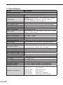
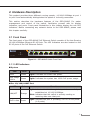
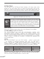
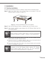
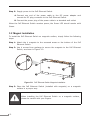
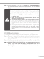
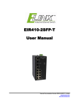
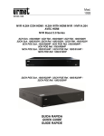
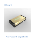
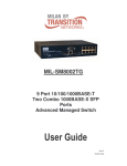
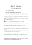
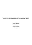
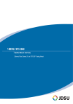
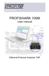
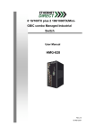
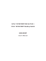
8-Port 10/100/1000T 802.3at PoE + 1-Port 10/100/1000T Desktop Switch GSD-908HP User’s Manual Trademarks Copyright © PLANET Technology Corp. 2014. Contents are subject to revision without prior notice. PLANET is a registered trademark of PLANET Technology Corp. All other trademarks belong to their respective owners. Disclaimer PLANET Technology does not warrant that the hardware will work properly in all environments and applications, and makes no warranty and representation, either implied or expressed, with respect to the quality, performance, merchantability, or fitness for a particular purpose. PLANET has made every effort to ensure that this User’s Manual is accurate; PLANET disclaims liability for any inaccuracies or omissions that may have occurred. Information in this User’s Manual is subject to change without notice and does not represent a commitment on the part of PLANET. PLANET assumes no responsibility for any inaccuracies that may be contained in this User’s Manual. PLANET makes no commitment to update or keep current the information in this User’s Manual, and reserves the right to make improvements to this User’s Manual and/or to the products described in this User’s Manual, at any time without notice. If you find information in this manual that is incorrect, misleading, or incomplete, we would appreciate your comments and suggestions. FCC Warning This equipment has been tested and found to comply with the limits for a Class A digital device, pursuant to Part 15 of the FCC Rules. These limits are designed to provide reasonable protection against harmful interference when the equipment is operated in a commercial environment. This equipment generates, uses, and can radiate radio frequency energy and, if not installed and used in accordance with the Instruction manual, may cause harmful interference to radio communications. Operation of this equipment in a residential area is likely to cause harmful interference in which case the user will be required to correct the interference at his own expense. CE Mark Warning This is a Class A product. In a domestic environment, this product may cause radio interference, in which case the user may be required to take adequate measures. Energy Saving Note of the Device This power required device does not support Standby mode operation. For energy saving, please remove the power cable to disconnect the device from the power circuit. Without removing power cable, the device will still consuming power from the power source. In the view of Saving the Energy and reduce the unnecessary power consuming, it is strongly suggested to remove the power connection for the device if this device is not intended to be active. WEEE Warning To avoid the potential effects on the environment and human health as a result of the presence of hazardous substances in electrical and electronic equipment, end users of electrical and electronic equipment should understand the meaning of the crossed-out wheeled bin symbol. Do not dispose of WEEE as unsorted municipal waste; WEEE has to be collected separately. Revision PLANET 8-Port 10/100/1000T 802.3at PoE + 1-Port 10/100/1000T Desktop Switch User’s Manual For Model: GSD-908HP Revision: 1.0 (JUNE, 2014) Part No.: 2351-AK3180-000 Table of Contents 1.Introduction................................................................................................ 5 1.1Checklist.............................................................................................. 5 1.2 Product Description............................................................................... 5 1.3Features.............................................................................................. 7 1.4 Specifications....................................................................................... 8 2. Hardware Description................................................................................... 9 2.1 Front Panel.......................................................................................... 9 2.1.1 LED Indicators............................................................................ 9 2.2 Rear Panel..........................................................................................10 3.Installation.................................................................................................11 3.1 Desktop Installation.............................................................................11 3.2 Magnet Installation..............................................................................12 3.3 Wall Mount Installation.........................................................................13 3.4 Protective Grounding Cable Installation..................................................14 3.4.1 Installation Environment with Grounding Bar................................14 3.4.2 Installation Environment without Grounding Bar............................15 3.5 Hardware Connection...........................................................................16 4.Troubleshooting..........................................................................................18 Appendix: A Networking Connection..................................................................19 A.1 PoE RJ-45 Port Pin Assignments............................................................19 A.2 Switch’s Data RJ-45 Pin Assignments - 1000Mbps, 1000Base-T...............19 A.3 10/100Mbps, 10/100Base-TX................................................................20 1.Introduction 1.1Checklist Check the contents of your package for the following parts: zz GSD-908HP x 1 zz User’s Manual x 1 zz External AC to DC Adapter x 1 zz Power Cord x 1 zz Wall Mount Kit x 1 zz Magnet / Screw x 4 zz Rubber Feet x 4 If any of these pieces are missing or damaged, please contact your dealer immediately; if possible, retain the carton including the original packing material, and use them again to repack the product in case there is a need to return it to us for repair. The term “PoE Ethernet Switch” mentioned in this user’s manual also means the GSD-908HP. 1.2 Product Description Centralized Power Distribution for Ethernet Networking The GSD-908HP, a new member in the PLANET 802.3af / 802.3at PoE Unmanaged Gigabit Ethernet Switch family, is an 8-port 10/100/1000T 802.3at Power over Ethernet + 1-port 10/100/1000T Desktop Switch with a total of 120 watts of PoE budget, which is an ideal solution to fulfilling the demand of sufficient PoE power for network applications with Gigabit Ethernet speed transmission. The eight 802.3af / 802.3at PoE Gigabit ports provides PoE power injector function which is able to drive 8 IEEE 802.3af compliant powered devices or 4 IEEE 802.3at compliant powered devices. The GSD-908HP also provides a simple, cost-effective and non-blocking Gigabit wire-speed performance. It comes with a metal compact housing, suitable for desktop deployment in SOHO office or department network application. 5 Perfectly Integrated Solution for IP PoE Camera and NVR System Different from the general IT industrial PoE Switch which usually comes with 12 or 24 PoE ports, the GSD-908HP provides eight 802.3af / 802.3at PoE Gigabit ports for catering to small scale of IP Surveillance networks at a lower total cost. The GSD-908HP comes with high performance switch architecture and 120-watt PoE power budget. The recorded video files from 8 PoE IP Cameras can be powered by the GSD-908HP and saved in the 8-channel NVR system or surveillance software to perform comprehensive security monitoring. For instance, one GSD-908HP can be combined with one 8-channel NVR and 8 PoE IP cameras as a kit for the administrators to centrally and efficiently manage the surveillance system in the local LAN and the remote site via Internet. Stable and High Performance Switch Architecture The GSD-908HP has a 4K MAC address table, featuring high performance switch architecture capable of providing the non-blocking 18Gbps switch fabric and wirespeed throughput as high as 13.3Mpps, which greatly simplifies the tasks of upgrading the LAN for catering to increasing bandwidth demands. Besides, the 802.3x Full-Duplex flow control function of the GSD-908HP enables PD devices and servers to be directly connected to the switch for wire-speed packet transfer performance without the risk of packet loss. The GSD-908HP RJ-45 copper interfaces support 10/100/1000Mbps AutoNegotiation at port 1 to port 9 for optimal speed detection through RJ-45 Category 6, 5 or 5e cables. It also supports standard Auto-MDI/MDI-X that can detect the type of connection to any Ethernet device without requiring special straight or crossover cables. Easy Cable Connection With data and power over Ethernet from one unit, the GSD-908HP reduces cabling requirements and eliminates the need for dedicated electrical outlets on the wall, ceiling or any unreachable place. A wire that carries both data and power can lower the installation costs, simplify the installation effort and eliminate the need for electricians or extension cords. Providing 8 PoE interfaces, the GSD-908HP is ideal for small businesses and workgroups requiring deploying the PoE for the wireless access points, IP-based surveillance camera or IP phones in any places easily, efficiently and cost-effectively. 6 1.3Features zz RJ-45 Interface Complies with IEEE 802.3, 10Base-T, IEEE 802.3u, 100Base-TX, IEEE 802.3ab, 1000Base-T 9-Port 10/100/1000Mbps Gigabit Ethernet Switch 8-Port supports 51V DC power to PoE Powered Device (Port 1 to port 8) zz Power over Ethernet Complies with IEEE 802.3af / 802.3at Power over Ethernet End-Span PSE Up to 8 IEEE 802.3af devices powered Supports PoE Power up to 15.4 watts for each PoE port Up to 4 IEEE 802.3at devices powered Supports PoE Power up to 30 watts for each PoE port 120-watt PoE budget Auto detects powered device (PD) Circuit protection prevents power interference between ports Remote power feeding up to 100m zz Switching Hardware based 10/100Mbps, Half / Full Duplex and 1000Mbps Full Duplex mode, Flow Control and Auto-negotiation and Auto MDI/MDI-X Features Store-and-Forward mode with wire-speed filtering and forwarding rates IEEE 802.3x flow control for Full Duplex operation and backpressure for Half Duplex operation Integrates address look-up engine, supporting 4K absolute MAC addresses 192 KB packet buffer 9K Jumbo frame supports at 1000Mbps speed duplex mode Automatic address learning and address aging Supports CSMA/CD protocol zz Hardware Made of metal and desktop size and wall-mount design LED indicators for system power, PoE usage 100%, per port PoE In-Use (Port 1 to port 8), per port Link / Act (10/100/1000Mbps, port 1 to port 9). 51V DC, 2.5A external power adapter FCC, CE Class A compliant 7 1.4 Specifications Model Hardware Specifications Network Connector PoE Inject Port LED Display Switch Architecture MAC Address Table Data Buffer Switch Fabric Switch Throughput Flow Control Power Requirements Power Consumption Dimensions (W x D x H) Weight Power over Ethernet PoE Standard PoE Power Supply Type GSD-908HP 9-Port RJ-45 for 10/100/1000Base-T 8-Port with 802.3af / 802.3at PoE injector function System: Power (Green), PoE Usage 100% (Green) Per PoE Port: PoE (Green), port 1 to port 8 LNK/ACT (Orange), port 1 to port 9 Store and forward 4K MAC address table with auto learning function 192 KB 18Gbps 13.3Mpps@64Bytes Back pressure for Half-Duplex. IEEE 802.3x Pause Frame for Full-Duplex DC 51V, 2.5A max. 120 watts / 409BTU 103 x 235 x 27 mm 628g IEEE 802.3af / 802.3at Power over Ethernet PSE End-Span Per Port 51V DC, 350mA. Max. 15.4 watts PoE Power Output Per Port 51V DC, 600mA. Max. 30 watts Power Pin Assignment 1/2(+), 3/6(-) PoE Power Budget 120 watts Max. Number of Class 2 PD 8 Max. Number of Class 3 PD 8 Max. Number of Class 4 PD 4 Standard Conformance EMI Safety FCC Class A, CE Operating Environment 0 ~ 50 degrees C Storage Environment -10 ~ 70 degrees C Operating Humidity 5 ~ 95%, relative humidity (non-condensing)_ Storage Humidity 5 ~ 95%, relative humidity (non-condensing) Standard Compliance 8 IEEE IEEE IEEE IEEE IEEE IEEE 802.3 802.3u 802.3ab 802.3x 802.3af 802.3at Ethernet Fast Ethernet Gigabit Ethernet Flow Control Power over Ethernet High Power over Ethernet 2.Hardware Description This product provides three different running speeds –10/100/1000Mbps at port 1 to port 9 and automatically distinguishes the speed of incoming connection. This section describes the hardware features of the GSD-908HP. For easier management and control of the switch, familiarize yourself with its display indicators, and ports. Front panel illustrations in this chapter display the unit LED indicators. Before connecting any network device to the GSD-908HP, please read this chapter carefully. 2.1 Front Panel The front panel of the GSD-908HP PoE Ethernet Switch consists of 9x Auto-Sensing 10/100/1000Mbps Ethernet RJ-45 Ports. The LED Indicators are also located on the RJ-45 ports of the PoE Ethernet Switch. LNK ACT PoE In-Use PWR PoE Usage 100% 1 GSD-908HP 2 3 4 5 6 7 8 9- Uplink Figure 2-1: GSD-908HP Switch Front Panel 2.1.1LED Indicators System LED Color Function PWR Green Light: Indicates the switch has power. PoE Usage 100% Green Light: Indicates the system has 100% PoE power usage. Per 10/100/1000T Port LED LNK/ACT Color Orange PoE In-Use Green Function Light: indicates the link through that port is successfully established at 10/100/1000Mbps. Blink: indicates that the switch is actively sending or receiving data over that port. Light: indicates the port is providing 51V DC in-line power (1-8 ports). 9 2.2 Rear Panel The rear panel of the PoE Ethernet Switch indicates a DC power socket, which accepts DC 51V input power; there is a security slot that allows using an antitheft lock to attach the PoE Ethernet Switch to a fixed object against theft. The grounding terminal provides lightning protection ability for the PoE Ethernet Switch. 51V DC Figure 2-2: GSD-908HP Switch Rear Panel Power Notice The device is a power-required device, meaning it will not work till it is powered. If your networks should be active all the time, please consider using UPS (Uninterrupted Power Supply) for your device. It will prevent you from network data loss or network downtime. In some areas, installing a surge suppression device may also help to protect your GSD-908HP from being damaged by unregulated surge or current to the GSD-908HP or the power adapter. Before startup Before your installation begins, please refer to the following for your cabling: 10/100/1000Base-T (Port 1 to Port 9) The 10/100/1000Base-T port comes with Auto-Negotiation capability, which automatically supports 1000Base-T, 100Base-TX and 10Base-T networks. Users only need to plug a working network device into the 10/100/1000Base-T port, and then turn on the PoE Ethernet Switch. The port will automatically run in 10Mbps, 20Mbps, 100Mbps or 200Mbps and 1000Mbps or 2000Mbps after negotiating with the connected device. Cabling Each 10/100/1000Base-T port uses RJ-45 sockets -- similar to phone jacks -- for connection of unshielded twisted-pair cable (UTP). The IEEE 802.3 / 802.3u / 802.3ab Fast / Gigabit Ethernet standard requires Category 5 UTP for 100Mbps 100Base-TX. 10Base-T networks can use Cat.3, 4, 5 or 1000Base-T uses Cat.5/5e/6 UTP (see table below). Maximum distance is 100 meters (328 feet). Port Type 10Base-T 100Base-TX 1000Base-T Cable Type Cat 3, 4, 5, 2-pair Cat.5 UTP, 2-pair Cat.5/5e/6 UTP, 4-pair Connector RJ-45 RJ-45 RJ-45 Any Ethernet devices like hubs/PCs can connect to the GSD-908HP PoE Ethernet Switch by using straight-through wires. The nine RJ-45 ports are auto-MDI/MDI-X, which can be used on straight-through or crossover cable. 10 3.Installation 3.1 Desktop Installation To install the PoE Ethernet Switch on desktop, simply follow the following steps: Step 1:Attach the rubber feet to the recessed areas on the bottom of the PoE Ethernet Switch, as shown in Figure 3-1. LNK ACT PoE In-Use PWR GSD-908H P PoE Usage 100% 1 2 3 4 5 6 7 8 9- Uplink Figure 3-1: Place the PoE Ethernet Switch on the Desktop Step 2: Place the PoE Ethernet Switch on desktop near an AC power source. Step 3: Keep enough ventilation space between the PoE Ethernet Switch and the surrounding objects. Note When choosing a location, please keep in mind the environmental restrictions discussed in Chapter 1, Section 4 under Specifications. Step 4: Connect your PoE Ethernet Switch to 802.3af / 802.3at complied Powered Devices (PD) and other network devices. A.Connect one end of a standard network cable to the 10/100/1000 RJ-45 ports on the front panel of the PoE Ethernet Switch. B.Connect the other end of the cable to the network devices such as printer servers, workstations, router, etc. Note Connection to the PoE Ethernet Switch requires UTP Category 6/5e/5 network cabling with RJ-45 tips. For more information, please see the Cabling Specifications in Appendix A. 11 Step 5: Supply power to the PoE Ethernet Switch. A.Connect one end of the power cable to the DC power adapter and connect its DC plug connector to the PoE Ethernet Switch. B.Connect the power plug of the power cable to a standard wall outlet. When the PoE Ethernet Switch receives power, the Power LED should remain solid Green. 3.2 Magnet Installation To install the PoE Ethernet Switch on magnetic surface, simply follow the following steps: Step 1:Attach the 4 magnets to the recessed areas on the bottom of the PoE Ethernet Switch. Step 2:Use 4 screws from package to secure the magnets to the PoE Ethernet Switch, as shown in Figure 3-2. GSD-908H P GSD-908HP PoE Usage LNK PWR 100% ACT PoE In-Us 1 2 3 e 4 5 6 7 8 9- Uplink Figure 3-2: PoE Ethernet Switch Magnets Installation Step 3:Place the PoE Ethernet Switch (installed with magnets) on a magnetic surface in a proper way. When installing the PoE Ethernet Switch on a magnetic surface, please be careful with your fingers. 12 Step 4: Proceed with Step 4 and Step 5 of session 3.1 Desktop Installation to connect the network cabling and supply power to your PoE Ethernet Switch. 1.Select the installation surface carefully. If the magnetic surface is not providing enough magnetism, the reliability of this installation will be influenced. 2.Please do not choose higher installation position and note vibration might cause PoE Ethernet Switch to fall down and damage or personal injury. 3.Please do not move the PoE Ethernet Switch often to avoid damage to the coated surface. 4.For connecting Ethernet cable to the PoE Ethernet Switch easily, please place the PoE Ethernet Switch with RJ-45 interface at a lower position. We also must pay attention to the weight of the installed Ethernet cables to avoid PoE Ethernet Switch to fall down. 5.Keep magnets away from specific objects such as magnetic card, computer and computer monitor, which are easy to be magnetized. Otherwise, the PoE Ethernet Switch malfunctions might happen. 3.3 Wall Mount Installation To install the PoE Ethernet Switch on the wall, simply follow the following steps: Step 1: There are 2 holes with 5mm diameter on the wall; the distance between the 2 holes is 110mm and the line through them must keep horizontal, as shown in Figure 3-3. Step 2: Install a conductor pipe inside the board hole and flush the edge of the conductor pipe with the wall surface. Step 3: Screw the bolts into the conductor pipe; the distance between the inside surface of the screw header and edge of conductor pipe should not be less than 2.5mm to make sure the PoE Ethernet Switch can be hung on the bolt tightly. 13 Step 4: Align two wall type holes at the bottom of the PoE Ethernet Switch with screws and hang the PoE Ethernet Switch on it. 51V DC Figure 3-3: PoE Ethernet Switch Wall Mount Installation 3.4 Protective Grounding Cable Installation The proper connection of the protective grounding cable is not only for quickly releasing the over voltage and over current from lightning strike, it also provides necessary protection for users’ body security. 3.4.1Installation Environment with Grounding Bar Connect one end of the protective grounding cable to the binding post on the grounding bar and fix the screws, as shown in Figure 3-4. 51V DC (2) (3) (1) (4) (1) AC Power Input Jack (2) Binding Post (3) Protective Grounding Cable (4) Grounding Bar Figure 3-4: Grounding Bar Installation 14 The PoE Ethernet Switch grounding cable should be connected to the engineering land in the IT room because the water hoses and lightning rods are not proper for grounding. 3.4.2Installation Environment without Grounding Bar 3.4.2.1 With mud land nearby and allowed to bury grounding bar Bury an angle iron or steel pipe (≥0.5m) into the mud land. The protective grounding cable should be welded to the angle iron or steel pipe and the welding point should be embalmed, as shown in Figure 3-5. 51V DC (2) (3) (1) (4) (5) (1) AC Power Input Jack (2) Binding Post (4) Earth (5) Angle Iron (3) Protective Grounding Cable Figure 3-5: Ground Conductor Installation 3.4.2.2 Not allowed to bury grounding bar. If not allowed to bury the grounding bar, directly connect the PoE Ethernet Switch to the grounding bar through the power cord. Please ensure the provided adapter that you use has a triplex plug and the power cord in the switchgear room or beside the AC power supply transformer is well-grounded, as shown in Figure 3-6. 51V DC Figure 3-6: Ground Power Cord Installation 15 3.5 Hardware Connection The PoE Ethernet Switch provides flexibility to build a standard network application or PoE network application quick and easily, simply follow the following steps: Standard Network Application: connecting end node or switch Step 1: Supply power to the PoE Ethernet Switch. A.Connect one end of the power cable to the DC power adapter and connect its DC plug connector to the PoE Ethernet Switch. B.Connect the power plug of the power cable to a standard wall outlet. When the PoE Ethernet Switch receives power, the Power LED should remain solid Green. Step 2:Connect PC or laptop to one port of the PoE Ethernet Switch using Category 5/5e/6 UTP cabling. Step 3: Use an Ethernet cable to connect one upstream network devices (such as another switch or router) to the uplink port on the switch, as shown in Figure 3-7. GSD-908HP XDSL Router Internet 1000Base-T UTP PC Laptop Laptop NAS Figure 3-7: End Node or Switch Connection PoE Network Application: department / workgroup PoE switch Step 1: Supply power to the PoE Ethernet Switch. A.Connect one end of the power cable to the DC power adapter and connect its DC plug connector to the PoE Ethernet Switch. B.Connect the power plug of the power cable to a standard wall outlet. When the PoE Ethernet Switch receives power, the Power LED should remain solid Green. 16 Step 2:Providing up to eight 802.3at / 802.3af PoE in-line interfaces, use an Ethernet cable to connect various 802.3at / 802.3af PD devices. Such as wireless AP, IP Phone and IP Camera devices, as shown in Figure 3-8. Backbone Switch Power Line (DC) DC 1000Base-T UTP 1000Base-T UTP with PoE PoE N GSD-908HP 2.4GHz 802.11n Power DC PoE N Laptop PoE PoE N PoE Wireless AP PoE VoIP Phone PTZ Camera PC PC PC Figure 3-8: Department / Workgroup PoE Switch Connection Note Since the GSD-908HP per PoE port supports 51V DC PoE power output, please check and assure the Powered Device’s (PD) acceptable DC power range is 51V DC. Otherwise, it will damage the Powered Device (PD). 17 4.Troubleshooting This chapter contains information to help you solve issues. If the PoE Ethernet Switch is not functioning properly, make sure the PoE Ethernet Switch is set up according to instructions in this manual. The Link / Act LED is not lit Solution: Check the cable connection and remove duplex mode of the PoE Ethernet Switch. Performance is bad Solution: Check the speed duplex mode of the partner device. The PoE Ethernet Switch is run at auto-negotiation mode and if the partner is set to half duplex, then the performance will be poor. 1000Base-T port link LED is lit, but the traffic is irregular Solution: Check that the attached device is not set to dedicate full duplex. Some devices use a physical or software switch to change duplex modes. Auto-negotiation may not recognize this type of full-duplex setting. Why the PoE Ethernet Switch doesn’t connect to the network Solution: Check the LNK/ACT LED on the PoE Ethernet Switch. Try another port on the PoE Ethernet Switch. Make sure the cable is installed properly and make sure the cable is the right type. Turn off the power. After a while, turn on power again. Why I connect my PoE device to PoE Ethernet Switch and it cannot power on Solution: 1.Please check the cable type of the connection from the PoE Ethernet Switch (port 1 to port 8) to the other end. The cable should be an 8-wire UTP, Category 5 or above, EIA568 cable within 100 meters. A cable with only 4-wire, short loop or over 100 meters will affect the power supply. 2.Please check and assure the device is fully complied with IEEE 802.3af / 802.3at standard. What is the power output of each PoE port? Solution: Each PoE port supports 51V DC, 350mA, max 15.4 watts power output. Detect and inject by the standard of IEEE 802.3af. Each PoE port supports 51V DC, 600mA, max 30 watts power output. Detect and inject by the standard of IEEE 802.3at. 18 Appendix: A Networking Connection A.1PoE RJ-45 Port Pin Assignments 12345678 PIN NO RJ-45 POWER ASSIGNMENT 1 Power + 2 Power + 3 Power - 6 Power - A.2Switch’s Data RJ-45 Pin Assignments - 1000Mbps, 1000Base-T PIN NO MDI MDI-X 1 BI_DA+ BI_DB+ 2 BI_DA- BI_DB- 3 BI_DB+ BI_DA+ 4 BI_DC+ BI_DD+ 5 BI_DC- BI_DD- 6 BI_DB- BI_DA- 7 BI_DD+ BI_DC+ 8 BI_DD- BI_DC- Implicit implementation of the crossover function within a twisted-pair cable, or at a wiring panel, while not expressly forbidden, is beyond the scope of this standard. 19 A.310/100Mbps, 10/100Base-TX When connecting your PoE Ethernet Switch to another Fast Ethernet switch, a bridge or a hub and a straight or crossover cable are necessary. Each port of the Switch supports auto-MDI/MDI-X detection. That means you can directly connect the Switch to any Ethernet devices without making a crossover cable. The following table and diagram show the standard RJ-45 receptacle/ connector and their pin assignments: RJ-45 Connector Pin Assignment PIN NO MDI Media Dependent Interface MDI-X Media Dependent Interface (Cross) 1 Tx + (transmit) Rx + (receive) 2 Tx - (transmit) Rx - (receive) 3 Rx + (receive) 4, 5 6 7, 8 Tx + (transmit) Not used Rx - (receive) Tx - (transmit) Not used The standard cable, RJ-45 pin assignment The standard RJ-45 receptacle/connector 20