1
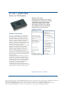
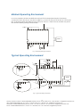
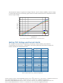
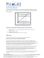
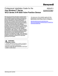
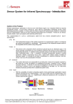
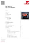
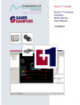
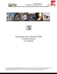
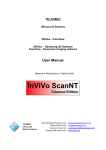
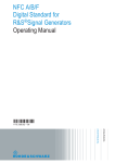
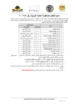
User Manual Rev. 09.01 09.01 valid from June 2009 PL-TEC 1-0305-PWM Germany and other countries: LASER COMPONENTS GmbH, Phone: +49 8142 2864 0, Fax: +49 8142 2864 11, [email protected] USA: LASER COMPONENTS IG, Inc., Phone: +1 603 821 7040, Fax: +1 603 821 7041, [email protected] Great Britain: LASER COMPONENTS (UK) Ltd., Phone: +44 1245 491 499, Fax: +44 1245 491 801, [email protected] France: LASER COMPONENTS S.A.S., Phone: +33 1 3959 5225, Fax: +33 1 3959 5350, [email protected] Table of Contents PL-TEC 1-0305-PWM .................................................................................................................. 3 Pin Assignments and Description ................................................................................................ 4 Minimal Operating Environment ................................................................................................. 5 Typical Operating Environment ................................................................................................... 5 Wheatstone Bridge ..................................................................................................................... 6 Temperature Setpoint and Monitor............................................................................................. 6 Setting TEC Voltage and Current Limits ...................................................................................... 7 Tec-Current Monitor ................................................................................................................... 8 Absolute Maximum Ratings (destroying limits) ............................................................................ 8 Warranty .................................................................................................................................... 8 2 Germany and other countries: LASER COMPONENTS GmbH, Phone: +49 8142 2864 0, Fax: +49 8142 2864 11, [email protected] USA: LASER COMPONENTS IG, Inc., Phone: +1 603 821 7040, Fax: +1 603 821 7041, [email protected] Great Britain: LASER COMPONENTS (UK) Ltd., Phone: +44 1245 491 499, Fax: +44 1245 491 801, [email protected] France: LASER COMPONENTS S.A.S., Phone: +33 1 3959 5225, Fax: +33 1 3959 5350, [email protected] PL-TEC 1-0305-PWM Rev. 09.02 valid from June 2009 PL-TEC 1-0305-PWM Driver for TEC-Modules Bipolar ±3A output Temperature stability up to 0.001°C Adjustable TEC current and voltage limiting to protect TEC-module Direct TEC temperature control No additional heat sink required Low-ripple and low-noise design Multiple monitoring outputs Technical Data:* Output current Output current limiting range Product Description: The PL-TEC 1-0305-PWM is a very small, safe, and most accurate temperature controller for Peltier thermoelectric cooler (TEC) modules. An ultra low-drift chopper amplifier maintains ±0.001°C temperature stability. Output current, rather than voltage, is directly controlled to eliminate current surges. Individual heating and cooling current limits and voltage limits provide the highest level of TEC protection. The PL-TEC 1-0305-PWM operates from a single supply and provides bipolar ±3A output by biasing the TEC between the outputs of two synchronous buck regulators. True bipolar operation controls temperature without “dead zones” or other nonlinearities at low load currents. The control system does not hunt when the set point is very close to the natural operating point, where only a small amount of heating or cooling is needed. An analog control signal precisely sets the TEC temperature. The actual TEC temperature and current can be monitored via analog outputs. In addition, separate over- and under-temperature outputs indicate when the TEC temperature is out of range. An on-chip voltage reference provides bias for a thermistor bridge. Through the new efficient design, the PL-TEC 1-0305-PWM itself requires no heat sink or other cooling method to reach its full output power. Max. output voltage (referred to the supply) Output voltage limiting range TEC Temperature monitor Supply voltage Temperature stability Monitor outputs Control inputs Power Dissipation Dimensions in mm Weight Operating temperature Bipolar 2,5 A, 3A peak** Heating: 0 .. 3 A Cooling 0 .. 3 A Independently limitable by external resistor - 4.3 .. + 4.3 V (@ +5V ) - 2.3 .. + 2.3 V (@ +3V) 0 .. 4.3 V by external resistor 0 .. 1.5 V** +3 .. +5 V single supply 0.001 K** - TEC temperature monitor - Over- and undertemperature output (open collector) - TEC current monitor - TEC temperature set point - enable (TTL level) < 2.5 W 30x18x7,5 mm DIP 24-6 package 8g -20 to + 55 ° C * Technical data is subject to change without further notice. ** See manual for detailed information. Optional Accessories: PL-TEC-BOB 3 Germany and other countries: LASER COMPONENTS GmbH, Phone: +49 8142 2864 0, Fax: +49 8142 2864 11, [email protected] USA: LASER COMPONENTS IG, Inc., Phone: +1 603 821 7040, Fax: +1 603 821 7041, [email protected] Great Britain: LASER COMPONENTS (UK) Ltd., Phone: +44 1245 491 499, Fax: +44 1245 491 801, [email protected] France: LASER COMPONENTS S.A.S., Phone: +33 1 3959 5225, Fax: +33 1 3959 5350, [email protected] Pin Assignments and Description Pin # Short Desc. Description 1, 2 GND GND 3 FB+ Feedback Voltage input (thermal setpoint, analog Voltage 0… 1.5 V in). See page 6 for details 4 REF 1,500 V Reference Voltage output. Max load 50 µA (>36k to GND) 5 Itec Tec Current-monitor output. The output voltage corresponds to the current by: Itec = (Ua -1,5 V)/0,4. A readout of 1,5 V means zero current, 1,9 V = 1,0 A pos, 0,7 V = 2 A neg. Accuracy +/- 10% 6 MaxIP Maximum Positive TEC Current. Connect MAXIP to REF to set default positive current limit +150mV / 0.05R = 3 A. This pin is tied to 1.5 V ref by an 47k Resistor. So use any resistor to GND to reduce maximum positive current. See page 7 for details. 7 MaxIN Maximum Negative TEC Current. Connect MAXIN to REF to set default negative current limit -150mV / 0.05R = 3 A. This pin is tied to 1.5 V ref by an 47k Resistor. So use any resistor to GND to reduce maximum negative current. See page 7 for details. 8 Rth+ Connect the NTC between Rth+ and Rth-. NTC value must be around 10k. 9 Rth- NTC return 10 GND GND 11,12 Tec + Power outlet for the TEC. Connect both pins together. 13,14 Tec - Power return for the TEC. Connect both pins together. 15 GND GND 16 n.c. 17 MaxV Maximum Bipolar TEC Voltage. Internal Resistor divider (47k to 1.5V and 150k to GND) provides the maximum voltage across the TEC. The maximum TEC voltage is four times the voltage on this pin. Connect any Resistor to GND to reduce MaxV-TEC-Voltage. See page 7 for details. 18 /Shdn Enable Input. Tie to Vcc to enable unit, a connection to GND will disable the unit. No internal pullup resistor. 19 /OT Over-Temperature Alarm. Open-drain output pulls low if temperature feedback rises 20mV (typically +1.5°C) above the set-point voltage. Typ. sinking current 4 mA 20 /UT Under-Temperature Alarm. Open-drain output pulls low if temperature feedback falls 20mV (typically +1.5°C) below the set-point voltage. Typ. sinking current 4 mA 21 Tntc NTC temperature monitor output: 0...3 V. See page 6 for details. 22,23,24 Vcc Supply Voltage input (single Supply +3 to +5 V) 4 Germany and other countries: LASER COMPONENTS GmbH, Phone: +49 8142 2864 0, Fax: +49 8142 2864 11, [email protected] USA: LASER COMPONENTS IG, Inc., Phone: +1 603 821 7040, Fax: +1 603 821 7041, [email protected] Great Britain: LASER COMPONENTS (UK) Ltd., Phone: +44 1245 491 499, Fax: +44 1245 491 801, [email protected] France: LASER COMPONENTS S.A.S., Phone: +33 1 3959 5225, Fax: +33 1 3959 5350, [email protected] Minimal Operating Environment For correct operation at least one additional 100k poti for the temperature setpoint is necessary: Connect the +5V to Pins 22, 23, 24, and 18; GND to 1,2,10 and 15; the poti to the Pins 2, 3 and 4; the NTC to the Pins 8 and 9 and finally the TEC to the pins 11&12 vs. 13&14. The TEC and NTC are part of the common butterfly package of laser diodes. +5V 24 23 22 21 20 19 18 17 16 15 14 13 Peltier + 1 2 3 4 5 6 7 8 9 10 11 12 Fig. 1: Minimal operating environment Typical Operating Environment 1,2 V TNTC 1 3 2 4 +5V 5 24 23 22 21 20 19 18 17 16 15 14 13 N.C N.C. Cblock Peltier + 1 2 3 4 5 1 2 3 4 5 6 7 8 9 10 11 12 Tsetpoint Fig. 2: Typical operating environment 5 Germany and other countries: LASER COMPONENTS GmbH, Phone: +49 8142 2864 0, Fax: +49 8142 2864 11, [email protected] USA: LASER COMPONENTS IG, Inc., Phone: +1 603 821 7040, Fax: +1 603 821 7041, [email protected] Great Britain: LASER COMPONENTS (UK) Ltd., Phone: +44 1245 491 499, Fax: +44 1245 491 801, [email protected] France: LASER COMPONENTS S.A.S., Phone: +33 1 3959 5225, Fax: +33 1 3959 5350, [email protected] Typically, the PL TEC 1-0305 PWM Driver can be operated using the above environment. The two resistors connected to Pins 6 and 7 adjust the maximum TEC-current and a resistor connected to Pin 17 adjusts the maximum TEC voltage corresponding to table 1 (page 7). Pins 20 and 19 are open collector outputs which can be used to drive LEDs to signal a critical over- or under-temperature condition, respectively. These diodes have to be an ultra low current type. The series resistors limit the current which flows into the Pins to a maximum of 4 mA. The voltage applied to pin 3 is adjusting the temperature setpoint. However, the signal from the NTC is not linear. See figure 4 for details. The current through the TEC can be monitored at pin 5. Depending on the power supply an additional blocking capacitor (CBlock) may be necessary. Wheatstone Bridge For improved temperature stability the reference network and the feedback network are linked to the same reference voltage. However, this yields in a full Wheatstone bridge. Any influence on the reference voltage will have the same effect on the measured temperature and the setpoint. 4 1,5 V rms 1µ 3 10 K 8 NTC 10 K 1,2 Fig. 3: Part of Fig 1. Temperature Setpoint and Monitor The temperature setpoint input voltage corresponds to the TEC-temperature through the voltage of the NTC. The voltage of the NTC again depends on its B-value and the temperature. Figure 4 shows the correlation between TEC-temperature and setpoint voltage for different B-values of 10kΩ-NTCs. 1,2 B=4500 1,1 B=3988 B=3380 1,0 Setpoint Voltage in V 0,9 0,8 0,7 0,6 0,5 0,4 0,3 0,2 0 5 10 15 20 25 30 35 40 45 50 Tem perature in °C Fig. 4: Setpoint voltage for different B-values of 10kR NTC-Resistors. 6 Germany and other countries: LASER COMPONENTS GmbH, Phone: +49 8142 2864 0, Fax: +49 8142 2864 11, [email protected] USA: LASER COMPONENTS IG, Inc., Phone: +1 603 821 7040, Fax: +1 603 821 7041, [email protected] Great Britain: LASER COMPONENTS (UK) Ltd., Phone: +44 1245 491 499, Fax: +44 1245 491 801, [email protected] France: LASER COMPONENTS S.A.S., Phone: +33 1 3959 5225, Fax: +33 1 3959 5350, [email protected] The temperature monitor is equal to the voltage of the NTC, but for a better readability, the NTC voltage is inverted and amplified. The following graph shows the relation between the NTC temperature and the monitor output voltage. 3,4 3,2 3,0 2,8 2,6 Monitor Voltage in V 2,4 2,2 2,0 1,8 1,6 1,4 1,2 1,0 B=4500 0,8 B=3988 0,6 B=3380 0,4 0,2 0,0 0 5 10 15 20 25 30 35 40 45 50 Tem perature in °C Fig. 5: Monitor voltage for different B-values of 10kR NTC-Resistors. Setting TEC Voltage and Current Limits TEC voltage and current limits are adjusted by connecting a resistor between ground and the corresponding pin of the PL-TEC-1-0305-PWM. The following table shows the relation between the resistor value and the voltage/current limit: Rext in kΩ Vtec,max in V Rext in kΩ Itec,max in A 10 1,05 10 0,53 12 1,22 15 0,73 15 1,45 22 0,96 18 1,66 33 1,24 22 1,91 47 1,50 27 2,19 68 1,77 33 2,48 100 2,04 39 2,72 150 2,28 47 3,00 220 2,47 56 3,26 330 2,63 68 3,55 470 2,73 82 3,81 680 2,81 100 4,08 1000 2,87 4,3 Open 3,00 Open Table 1: Resistor values for TEC current and voltage limits 7 Germany and other countries: LASER COMPONENTS GmbH, Phone: +49 8142 2864 0, Fax: +49 8142 2864 11, [email protected] USA: LASER COMPONENTS IG, Inc., Phone: +1 603 821 7040, Fax: +1 603 821 7041, [email protected] Great Britain: LASER COMPONENTS (UK) Ltd., Phone: +44 1245 491 499, Fax: +44 1245 491 801, [email protected] France: LASER COMPONENTS S.A.S., Phone: +33 1 3959 5225, Fax: +33 1 3959 5350, [email protected] Tec-Current Monitor The current which is driven through the TEC module can be monitored at PIN 5 (Itec). The output voltage corresponds to the current by: Itec = (Ua -1,5 V)/0,4. A readout of 1,5 V means zero current, 1,9 V = 1,0 A pos, 0,7 V = 2 A neg. Accuracy +/-10%. The diagram shows the full trace including the internal offset. 3,00 2,00 1,00 0,00 itec in A -1,00 -2,00 -3,00 -4,00 0 0,5 1 1,5 2 2,5 3 Umess in V Fig. 6: TEC current monitor output voltage vs. TEC current Absolute Maximum Ratings (destroying limits) All Input Pins must not exceed the voltage range below zero (GND) and beyond VCC VCC Limit: +6V Peak TEC-Current: +/- 4.5 A Max /UT /OT current: 10mA Ref-Voltage: Current Sink (into Pin) 100µA, Source 800µA Warranty There are no warranties, express or implied, including any implied warranty of fitness for a particular purpose nor any IMPLIED WARRANTY OF MERCHANTIBILITY made by PicoLAS GmbH except as follows: PicoLAS warrants equipment manufactured by it to be free from defects in materials and/or workmanship under conditions of normal use for a period of one year from the date of shipment to the purchaser. PicoLAS will repair or replace, at PicoLAS´ option, any product manufactured by it which is shown to be defective or fails to perform within specifications within one year from the date of shipment to the purchaser. OEM, modified and custom items of equipment are similarly warranted, for a period of ninety (90) days from date of shipment to the purchaser. Equipment claimed to be defective must be returned, transportation prepaid, to PicoLAS in Aachen, Germany, within the warranty period. Returns must be preauthorized by contact with PicoLAS´ customer service department. Returns without an RMA-Number and/or incorrect RMA documentation and/or without prepaid transportation will be refused. Written documentation of such preauthorization shall be included with the returned item. At PicoLAS´ discretion, PicoLAS may elect to repair or replace the equipment claimed to be defective or refund the original purchase price, plus taxes and transportation charges incurred by the purchaser. 8 www.lasercomponents.com 06/10 / V1 / HW / picolas/ manual-pl-tec_1-0305-pwm.pdf Germany and other countries: LASER COMPONENTS GmbH, Phone: +49 8142 2864 0, Fax: +49 8142 2864 11, [email protected] USA: LASER COMPONENTS IG, Inc., Phone: +1 603 821 7040, Fax: +1 603 821 7041, [email protected] Great Britain: LASER COMPONENTS (UK) Ltd., Phone: +44 1245 491 499, Fax: +44 1245 491 801, [email protected] France: LASER COMPONENTS S.A.S., Phone: +33 1 3959 5225, Fax: +33 1 3959 5350, [email protected]