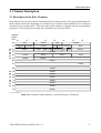
1
VME - ISER12
Intelligent Board for
12 serial Interfaces
Software Manual
VME-ISER12 Software Manual Rev. 1.0
NOTE
The information in this document has been carefully checked and is believed to be entirely reliable.
esd makes no warranty of any kind with regard to the material in this document, and assumes no
responsibility for any errors that may appear in this document. esd reserves the right to make
changes without notice to this, or any of its products, to improve reliability, performance or design.
esd assumes no responsibility for the use of any circuitry other than circuitry which is part of a
product of esd gmbh.
esd does not convey to the purchaser of the product described herein any license under the patent
rights of esd gmbh nor the rights of others.
esd electronic system design gmbh
Vahrenwalder Str. 205
30165 Hannover
Germany
Phone:
Fax:
E-mail:
Internet:
+49-511-372 98-0
+49-511-372 98-68
[email protected]
www.esd-electronics.com
USA / Canada
7667 W. Sample Road
Suite 127
Coral Springs, FL 33065
USA
Phone:
Fax:
E-mail:
+1-800-504-9856
+1-800-288-8235
[email protected]
VME-ISER12 Software Manual Rev. 1.0
Document file:
I:\texte\Doku\MANUALS\VME\ISER12\ISER12_01s.en6
Date of print:
31.10.2000
Described Firmware-Version:
isers50b
Changes in the Chapters
The changes in the user’s manual listed below effect changes in the hardware, as well as changes
in the description of the facts only.
Chapter
-
Changes versus previous version
First version.
Further technical changes are subject to change without notice.
VME-ISER12 Software Manual Rev. 1.0
VME-ISER12 Software Manual Rev. 1.0
Content
Content
1. Introduction . . . . . . . . . . . . . . . . . . . . . . . . . . . . . . . . . . . . . . . . . . . . . . . . . . . . . . . . . . . . . . . . . 3
1.1 General . . . . . . . . . . . . . . . . . . . . . . . . . . . . . . . . . . . . . . . . . . . . . . . . . . . . . . . . . . . . . . . 3
1.2 Channel Overview . . . . . . . . . . . . . . . . . . . . . . . . . . . . . . . . . . . . . . . . . . . . . . . . . . . . . . 4
1.2.1 Channel Types . . . . . . . . . . . . . . . . . . . . . . . . . . . . . . . . . . . . . . . . . . . . . . . . . . 4
1.2.2 Tasks of the VME Master Servers . . . . . . . . . . . . . . . . . . . . . . . . . . . . . . . . . . 4
1.3 Initialization of the System . . . . . . . . . . . . . . . . . . . . . . . . . . . . . . . . . . . . . . . . . . . . . . . 5
1.4 The Channel Structure . . . . . . . . . . . . . . . . . . . . . . . . . . . . . . . . . . . . . . . . . . . . . . . . . . . 6
1.4.1 Chaining of the Channels . . . . . . . . . . . . . . . . . . . . . . . . . . . . . . . . . . . . . . . . . 6
1.4.2 Description of the individual Channel Locations . . . . . . . . . . . . . . . . . . . . . . . 8
1.5 Data Channel Management . . . . . . . . . . . . . . . . . . . . . . . . . . . . . . . . . . . . . . . . . . . . . . 12
1.5.1 General . . . . . . . . . . . . . . . . . . . . . . . . . . . . . . . . . . . . . . . . . . . . . . . . . . . . . . 12
1.5.2 Overview to the Channels with Chaining via Pointer . . . . . . . . . . . . . . . . . . . 12
1.6 Buffer Allocation . . . . . . . . . . . . . . . . . . . . . . . . . . . . . . . . . . . . . . . . . . . . . . . . . . . . . . 15
1.6.1 Memory Allocation via Semaphore . . . . . . . . . . . . . . . . . . . . . . . . . . . . . . . . 15
1.6.2 Example of a Buffer Allocation . . . . . . . . . . . . . . . . . . . . . . . . . . . . . . . . . . . 15
2. Channel Description . . . . . . . . . . . . . . . . . . . . . . . . . . . . . . . . . . . . . . . . . . . . . . . . . . . . . . . . .
2.1 Description of the Data Channels . . . . . . . . . . . . . . . . . . . . . . . . . . . . . . . . . . . . . . . . .
2.2 Description of the Parameter Channel . . . . . . . . . . . . . . . . . . . . . . . . . . . . . . . . . . . . . .
2.2.1 Structure of the Parameter Channel . . . . . . . . . . . . . . . . . . . . . . . . . . . . . . . .
2.2.2 Description of the Parameter . . . . . . . . . . . . . . . . . . . . . . . . . . . . . . . . . . . . . .
2.2.3 Command Handing-over via the Parameter Channel . . . . . . . . . . . . . . . . . . .
2.3 Description of the Interrupter Channel . . . . . . . . . . . . . . . . . . . . . . . . . . . . . . . . . . . . .
2.3.1 Structure of the Interrupter Channel . . . . . . . . . . . . . . . . . . . . . . . . . . . . . . . .
2.3.2 Description of the Interrupter Channel Cells . . . . . . . . . . . . . . . . . . . . . . . . .
17
17
19
19
20
25
26
26
28
3. The local VME-ISER Server . . . . . . . . . . . . . . . . . . . . . . . . . . . . . . . . . . . . . . . . . . . . . . . . . . .
3.1 Functional Description of the local VME-ISER Server . . . . . . . . . . . . . . . . . . . . . . . .
3.1.1 Output Channels . . . . . . . . . . . . . . . . . . . . . . . . . . . . . . . . . . . . . . . . . . . . . . .
3.1.2 Input Channels . . . . . . . . . . . . . . . . . . . . . . . . . . . . . . . . . . . . . . . . . . . . . . . .
3.1.3 Interrupt Operation . . . . . . . . . . . . . . . . . . . . . . . . . . . . . . . . . . . . . . . . . . . . .
3.1.4 Time-Out . . . . . . . . . . . . . . . . . . . . . . . . . . . . . . . . . . . . . . . . . . . . . . . . . . . . .
3.1.5 Receive Error Mode . . . . . . . . . . . . . . . . . . . . . . . . . . . . . . . . . . . . . . . . . . . .
3.2 Examples for the VME-ISER Server . . . . . . . . . . . . . . . . . . . . . . . . . . . . . . . . . . . . . . .
3.2.1 Example: Initialization of the VMEbus Master . . . . . . . . . . . . . . . . . . . . . . .
3.2.2 Example: Data Output to Interface 2 without IRQ . . . . . . . . . . . . . . . . . . . . .
3.2.3 Example: Data Input from Interface 8 . . . . . . . . . . . . . . . . . . . . . . . . . . . . . .
3.2.4 Example: Setting the Parameter of Interface 1 . . . . . . . . . . . . . . . . . . . . . . . .
3.3 User Protocols . . . . . . . . . . . . . . . . . . . . . . . . . . . . . . . . . . . . . . . . . . . . . . . . . . . . . . . .
3.3.1 Function Description . . . . . . . . . . . . . . . . . . . . . . . . . . . . . . . . . . . . . . . . . . . .
3.3.2 Conditions for the Use of User-Specific Rx-Protocols/Filters . . . . . . . . . . . .
3.3.3 Register and Structure Declarations . . . . . . . . . . . . . . . . . . . . . . . . . . . . . . . .
3.3.4 Protocol Embedding for Rx-Operation . . . . . . . . . . . . . . . . . . . . . . . . . . . . . .
31
31
31
31
32
32
34
35
35
36
37
38
39
39
39
40
43
VME-ISER12 Software Manual Rev. 1.0
1
2
VME-ISER12 Software Manual Rev. 1.0
Introduction
1. Introduction
1.1 General
This manual describes the serial VMEbus interface boards VME-ISER8 and VME-ISER12.
A large part of the descriptions is valid for the VME-ISER8 and VME-ISER12 board. In the following
both boards are summarized under the concept VME-ISER.
Special data which concern only one of these boards are pointed to in corresponding places.
The VME-ISER8 is an intelligent interface board for the VMEbus, which locally supervises 8
asynchronous and 2 optionally synchronous or asynchronous serial interfaces.
The VME-ISER12 has got the same number of interfaces as the VME-ISER8. Two transition modules
of type ESP360 can optionally be attached to VME-ISER12. In coherence with these modules the VMEISER12 offers 10 asynchronous and 2 synchronous/asynchronous serial interfaces.
The user operates to a linear memory and is relieved of I/O supervision tasks by the local CPU.
The memory accessible to the user is organized in so-called channels, which consist of a header and a
data range. The length of a channel amounts to 256 bytes (128 bytes net data), or 1024+128 bytes * (1
kbyte net data).
The structure of the header is identical for all occurring types of channels, the different channels differ
in corresponding entries in the header of the channel.
The status of the serial interfaces and the setting of the serial interfaces parameters is transparently
readable, resetting of the parameter ensues synchronously to the I/O transfer.
VME-ISER12 Software Manual Rev. 1.0
3
Introduction
1.2 Channel Overview
1.2.1 Channel Types
The system consists of following types of channels:
- the parameter channels
1 channel per serial interface
- the data channel
1 receive channel (1 kbyte)
1 transmit channel (1 kbyte)
26 transmit channels (128 bytes each)
- the interrupter channel
1 channel per board
Channels are software structures, which are chained by pointers.
The 'ROOT pointer', as well as a 'Card Id' are at fixed addresses.
1.2.2 Tasks of the VME Master Servers
The VME master server for the serial interfaces must essentially fulfill the following tasks:
- Search a free channel and occupy this channel
- Entry of the transfer mode
- (Data transfer to the VME-ISER memory for transmit operation)
- Activation of the slave server (local interrupt generation)
- Polling on 'ready' or reactivation by VME interrupt
- (Data transfer from the VME-ISER memory for receive operation)
- Channel enable
4
VME-ISER12 Software Manual Rev. 1.0
Introduction
1.3 Initialization of the System
In the following all addresses are indicated relatively to the card base address and must be addressed
correspondingly by the VME master CPU.
After a system reset the local CPU initializes its local memory and rebuilds the channel pointer chain.
This can take up to 2 sec depending on the memory size. After a restart the master CPU should check
the following entries:
- read access to the base address of the slave board.
If the board responds with a 'DTACK signal', it is physically available at the correspondent address;
otherwise a 'BUSERROR' occurs (e.g. via time- out) because the board is not available
>> abort of the initialization.
- check of the address CPUID = $0998 to: $49534552.L
The local CPU must have an ASCII entry: "ISER" =($49, $53, $45, $52).
- check of address ANCHOR = $099C to unequal to $0
The local CPU inserts the ROOT pointer at the buffer structure (default: $00008000.L)
The local CPU has now built up the buffer structure described in the following, which enables a
communication with the master CPU.
VME-ISER12 Software Manual Rev. 1.0
5
Introduction
1.4 The Channel Structure
1.4.1 Chaining of the Channels
All channels are chained by pointers, where it must be distinguished between a memory chaining and
a forward/backward chaining.
The memory chaining connects all available channels, while the forward/backward chaining only
connects those channels related to the corresponding interface.
Memory Chaining:
Sequential chaining
The root pointer to the first available channel is a longword at the address ANCHOR
=$0099C, the pointer to the next channel (forward pointer) is a longword each time in the
location iofor of the channel header. The forward pointer of the last channel points back to the
first channel.
As default ANCHOR is set to $00008000. All addresses listed in the tables refer to this base,
but are relocatable without restrictions.
The length of a channel normally is 256 bytes and is divided into 128 bytes of header and 128
bytes of data.
Star-shaped chaining (from Software-Rev. iser 50b)
The star-shaped chaining speeds up the snapping of the addresses of the channels. In the
interrupt channel the successive addresses of all parameter channels can be found. In every
parameter channel the addresses of the assigned Tx- and Rx-channels are stored.
Note:
The sequential chaining and the star-shaped chaining are both available and can be used alternatively.
6
VME-ISER12 Software Manual Rev. 1.0
Introduction
Address
Offset
HEX
+0
+2
+4
+6
+8
+A
+C
+E
00
iofor
ioback
iotyp
10
sema iostat iocmmd
ionext
iolev iovec
iobnum
iolen
20
iobuff
iomode
iotout iodrv
iofnam...
iorecl
iostio ioldn
30
...iofnam...
40
...iofnam
ioentr
50
iorxin
iofree...
60
iotent
iofree
...iofree...
70
80
ioname
...iofree
iodata...
90
...iodata...
A0
...iodata...
B0
...iodata...
C0
...iodata...
D0
...iodata...
E0
...iodata...
F0
...iodata
User read/write cells
User read-only cells
User don't care
Table 1.4.1: Internal Channel Structure with READ/WRITE Assignment of the Cells
VME-ISER12 Software Manual Rev. 1.0
7
Introduction
1.4.2 Description of the individual Channel Locations
Summary of the channel locations
Offset
[HEX]
Organization
iofor
ioback
iotyp
ioname
00
04
08
0A
longword
longword
word
6 byte ASCII
iosema
iostat
iocmmd
ionext
10
11
12
14
byte
byte
word
longword
ioilev
ioivec
iobnum
18
19
1A
byte
byte
word
iolen
iobuff
iorecl
1C
20
24
longword
longword
word
iostio
ioldn
iomode
iotout
iodrv
iofnam
ioentr
26
27
28
2A
2B
2C ... 43
44
byte
byte
word
byte
byte
ASCII
longword
iotent
iofree
iorxln
iodata
48
4C ... 7F
50
80 ... FF
80 ... 47F
longword
Name
word
byte
byte
Description
Pointer to next channel
not used
channel type (see below)
channel identifier as character
string
channel semaphore
channel status
channel command
forward / backward pointer to
next channel
VME-Irq-Level for Slave-Irq
VME-Irq-Vektor for Slave-Irq
number of the specific channel
type
length of the data range
pointer to data range
number of the data in the data
range
I/O status
Interface no. 1 ... 10
transmit / receive mode
time-out
reserved
reserved
pointer to user protocol (only
parameter channel)
reserved for Tx-server
reserved
number of received data
data range (128 byte channels)
data range (1 Kbyte-channels)
Default/Preset
$0000000
preset: $00
preset: $00
preset: $0000
default: $00
default: $0000
default: $0000
Table 1.4.2: Description of the Channel Cells
8
VME-ISER12 Software Manual Rev. 1.0
Introduction
Explanation of the individual channel cells
iofor
supports the memory chaining of the channels. iofor always points to the start address of
the next channel, iofor of the last channel points to the first channel again.
ioback
points to the start address of the preceding channel
iotyp
is the channel identifier and distinguishes the following channel types:
- $FFFF interrupter channel
- $000C parameter-channel
- $0014 default channel (not used)
- $0018 buffer
- $001C buffer-channel (not used)
- $0114 Tx-buffer long
- $0214 Rx-buffer long
ioname
contains the channel identifier as a 6 bytes ASCII string and a consecutive numbering:
- Irch
interrupter channel
- PARAxy
parameter channel
with xy = 01, 02, ... 09, 0A
- TBUFxy
transmit buffer_long
with xy = 01, ... 0A
- RBUFxy
receive buffer_long
with xy = 01,... 0A
- Buffxz
transmit buffer (128 byte)
with x = 1, ... A
z = a, b,...z
iosema
is covered with the channel semaphore and with the channel status bit:
- Bit 7
semaphore: '0' -- channel is free
'1' -- channel is occupied
- Bit 6 - 1
reserved, default: '0'
- Bit 0
channel status:'0' -- channel is busy
'1' – channel is ready
iostat
is not yet supplied and is preset to $0
iocmmd
is the channel command and is only necessary for setting the interface parameters (see
interface parameter setting, from page 19).
ionext
is the pointer to the next data channel. Is only used for data channels, otherwise 0.
ioilev und ioivec
determine the slave interrupt behaviour. If ioilev and ioivec = 0, then the slave will not
generate an interrupt at the end of the instruction corresponding to the channel, but only
iosema is set analogously. Otherwise an IRQ on the VMEbus with the IRQ level ioilev
( 1..7 ) will be generated by the IRQ vector ioivec ( $00 .. $FF).
iobnum
contains the consecutive numbering of the channels.
For the interrupter channel iobnum has a value of 0.
VME-ISER12 Software Manual Rev. 1.0
9
Introduction
iolen
contains the available data buffer length. If the data buffer is located within the channel
structure (default), then iolen = $00080 == 128 bytes, or $400 respectively. External
data may have an unlimited length.
iobuff
is the pointer to the data buffer of the corresponding pointer channel. As default iobuff
points to iodata. At external data buffers iobuff may point to any local address, so that
addressing the data buffer must use the actual content of iobuff!
iorecl
determines the number of valid data in the data range. (number of data to be sent or
received).
If iorecl is negative, i.e. the MSB is set, the transmission has been stopped with error!
error codes:
$8007 - time-out
$801E - framing error
$801F - overrun error
$8020 - parity error
$8046 - break detected
iostio
is not yet supplied and is preset to $00.
ioldn
contains the channel server no. (1,...,10)
iomode
supports the setting of the data direction (transmit/receive operation) as well as setting the
receiving protocol parameters:
BitNo
Mnemo
15
MODBWA
14
MODBOU
Description
0
After transmission of all data no IRQ will be generated, the requested
channel will automatically be released again by the slave
1
After transmission of all data ready will be set iosema, or the indicated
IRQ will be generated respectively. The requested channel will not be
released by the slave.
0
Identification: receive channel
1
Identification: transmit channel
13
MODBOU
1
After detection of a <cr> ($0D) the reception of this channel will be
terminated.
12
MODBLF
1
After detection of a <lf> ($0A) the reception of this channel will be
terminated.
11
MODBEO
1
After detection of a <eot> ($04) the reception of this channel will be
terminated.
10
MODBSC
-
suppress_command: actually not connected
9
MODBNE
-
no_echo: actually not connected
8
MODBIN
0
no binary transfer
1
binary transfer: no end check, no software-handshake
Table 1.4.3: Bits of iomode
10
VME-ISER12 Software Manual Rev. 1.0
Introduction
Bit 7-0 of iomode are reserved as mode extension bits. The following combinations are
already defined:
- $00
- $08
normal I/O transfer (default)
only for receive operation:
All characters in the local buffers will be deleted.
iotout
time-out value
The MSB (bit 7) enables the Time_Out supervision of the channel.
If no transfer into an active channel buffer occurs, after the time T_Out the channel will be
released and the status Time_Out is returned! (via iorecl).
iofnam
is reserved for ASCII entries (up to 24 bytes).
Actually following entry will be evaluated:
On the ASCII string SCAN in the first 4 bytes of iofnam the following return conditions
are valid for a receive channel:
1.) Return of the buffer, if <iorecl> data have been received
2.) Return of the buffer, if one of the end conditions specified in <iomode> is valid.
3.) Return of the buffer, if no more data are available in the local interrupt buffer, i.e. if the
interrupt buffer is empty, the receive channel is returned immediately with <iorecl>=0.
For all other entries into iofnam only the end conditions 1.) and 2.) are valid. With the entry
PROT data are received via a special user protocol.
ioentr
supports the embedding of an user-specific receive protocol (only parameter channel). The
start address of a protocol loaded into a free memory area is registered here.
iotent
is reserved for embedding of a user-specific transmit protocol (only parameter channel).
iorxln
determines the number of valid received data, specially in the error case.
iofree
is actually not used and is preset to $00.
iodata
is the default data buffer of a channel and has a length of 128 bytes, or 1 kbyte respectively
(TBUFxy, RBUFxy).
Writing to memory out of the data buffer limits will destroy the I/O structure!
VME-ISER12 Software Manual Rev. 1.0
11
Introduction
1.5 Data Channel Management
1.5.1 General
As mentioned above, the channels are divided into parameter channels, buffer channels, default
channels and interrupter channels. To each serial interface a parameter (TX) buffer, a default Tx buffer,
an Rx buffer, and a number of buffers of the 'Buffer-Pool' are allocated.
The parameter buffer, the Tx buffer and the Rx buffer are exclusively allocated to the corresponding
interface. As a principle the buffers may be used by any channel. The pointer chaining results in a
priorized buffer allocation to the corresponding interface channels.
The chaining of the TX buffers and of the buffer channels is displayed in the following tables. The
forward/backward pointer ionext allocates the corresponding Tx buffer channel to a buffer. The ionext
pointer of the last buffer points to the Tx buffer again.
This channel distribution has been chosen for a very flexible memory allocation, while the searching
algorithm remains quick and simple.
1.5.2 Overview to the Channels with Chaining via Pointer
Channel Root Pointer
Address
[HEX]
Content
[HEX]
Remarks
0099C
08000
Start address of the buffer range
Table 1.5.1: Channel Root Pointer to Address ANCHOR
12
VME-ISER12 Software Manual Rev. 1.0
Introduction
Channel Header
Buffer
Number
[DEZ]
Address
[HEX]
iofor
[HEX]
0
08000
08100
0
1
08100
08200
2
08200
3
Remarks
ionext
[HEX]
iolen
[HEX]
ionam
0
0
80
Irch__
interrupter channel
1
1
0
80
PARA01
parameter channel 1
08300
2
2
0
80
PARA02
parameter channel 2
08300
08400
3
3
0
80
PARA03
parameter channel 3
4
08400
08500
4
4
0
80
PARA04
parameter channel 4
5
08500
08600
5
5
0
80
PARA05
parameter channel 5
6
08600
08700
6
6
0
80
PARA06
parameter channel 6
7
08700
08800
7
7
0
80
PARA07
parameter channel 7
8
08800
08900
8
8
0
80
PARA08
parameter channel 8
9
08900
08A00
9
9
0
80
PARA09
parameter channel 9
10
08A00
08B00
A
10
0
80
PARA0A
parameter channel 10
iobnum
ioldn
[HEX]
Table 1.5.2: Interrupter Channel and Parameter Channels
Channel Header
Buffer
Number
[DEZ]
Address
[HEX]
iofor
[HEX]
11
08B00
08F80
B
12
08F80
09400
13
09400
14
iobnum
ioldn
[HEX]
Remarks
ionext
[HEX]
iolen
[HEX]
ionam
1
0E500
400
TBUF01
transmit buffer 01
C
1
08F80
400
RBUF01
receive buffer 01
09880
D
2
0FF00
400
TBUF02
transmit buffer 02
09880
09D00
E
2
09880
400
RBUF02
receive buffer 02
15
09D00
0A180
F
3
11900
400
TBUF03
transmit buffer 03
16
0A180
0A600
10
3
0A180
400
RBUF03
receive buffer 03
17
0A600
0AA80
11
4
13300
400
TBUF04
transmit buffer 04
18
0AA80
0AF00
12
4
0AA80
400
RBUF04
receive buffer 04
19
0AF00
0B380
13
5
14B00
400
TBUF05
transmit buffer 05
20
0B380
0B800
14
5
0B380
400
RBUF05
receive buffer 05
21
0B800
0BC80
15
6
16700
400
TBUF06
transmit buffer 06
22
0BC80
0C100
16
6
0BC80
400
RBUF06
receive buffer 06
23
0C100
0C580
17
7
18100
400
TBUF07
transmit buffer 07
24
0C580
0CA00
18
7
0C580
400
RBUF07
receive buffer 07
25
0CA00
0CE80
19
8
19B00
400
TBUF08
transmit buffer 08
26
0CE80
0D300
1A
8
0CE80
400
RBUF08
receive buffer 08
27
0D300
0D780
1B
9
1B500
400
TBUF09
transmit buffer 09
28
0D780
0DC00
1C
9
0D780
400
RBUF09
receive buffer 09
29
0DC00
0E080
1D
10
1CF00
400
TBUF0A
transmit buffer 0A
30
0E080
0E500
1E
10
0E080
400
RBUF0A
receive buffer 0A
Table 1.5.3: Transmit and Receive Buffer
VME-ISER12 Software Manual Rev. 1.0
13
Introduction
Channel Header
Buffer
Number
[DEZ]
Address
[HEX]
iofor
[HEX]
31
0E500
0E600
1F
32
0E600
0E700
:
:
55
ionext
[HEX]
iolen
[HEX]
ionam
1
0E600
80
BUFF1a
20
1
0E70
80
BUFF1b
:
:
:
:
:
:
0FD00
0FE00
37
1
0FE00
80
BUFF1y
56
0FE00
0FF00
38
1
08800
80
BUFF1z
57
0FF00
10000
39
2
10000
80
BUFF2a
:
:
:
:
:
:
:
:
82
11800
11900
52
2
09400
80
BUFF2z
83
11900
11A00
53
3
11A00
80
BUFF3a
:
:
:
:
:
:
:
:
108
13200
13300
6C
3
09D00
80
BUFF3z
109
13300
13400
6D
4
13400
80
BUFF4a
:
:
:
:
:
:
:
:
134
14C00
14D00
86
4
0A600
80
BUFF4z
135
14D00
14E00
87
5
14E00
80
BUFF5a
:
:
:
:
:
:
:
:
160
16600
16700
A0
5
0AF00
80
BUFF5z
161
16700
16800
A1
6
16800
80
BUFF6a
:
:
:
:
:
:
:
:
186
18000
18100
BA
6
0B800
80
BUFF6z
187
18100
18200
BB
7
18200
80
BUFF7a
:
:
:
:
:
:
:
:
212
19A00
19B00
D4
7
0C100
80
BUFF7z
213
19B00
19C00
D5
8
19C00
80
BUFF8a
:
:
:
:
:
:
:
:
238
1B400
1B500
EE
8
0CA00
80
BUFF8z
239
1B500
1B600
EF
9
1B600
80
BUFF9a
:
:
:
:
:
:
:
:
264
1CE00
1CF00
108
9
03D00
80
BUFF9z
265
1CF00
1D000
109
10
1D000
80
BUFFAa
:
:
:
:
:
:
:
:
289
1E700
1E800
121
10
1E800
80
BUFFAy
290
1E800
08000
122
10
0DC00
80
BUFFAz
iobnum
ioldn
[HEX]
Remarks
26 buffer for channel 1
26 buffer for channel 2
26 buffer for channel 3
26 buffer for channel 4
26 buffer for channel 5
26 buffer for channel 6
26 buffer for channel 7
26 buffer for channel 8
26 buffer for channel 9
26 buffer for channel 10
Table 1.5.4: Buffer Channels 1 to 10
14
VME-ISER12 Software Manual Rev. 1.0
Introduction
1.6 Buffer Allocation
1.6.1 Memory Allocation via Semaphore
For a multitasking and multiuser memory management the memory allocation ensues via a semaphore,
which can be accessed by the indivisible assembler command TAS.
Beginning with the corresponding default channel the semaphore of the channels is occupied.
On a successful access the corresponding channel is occupied. If not, the next buffer must be
determined by ionext. Abort and wait conditions may be a certain number of unsuccessful accesses or
the detection of 'wrap-around' (new_pointer < old_pointer).
After executing the I/O instruction either the slave server returns the channel by releasing the semaphore
or the master must decide, when the channel will be available again.
1.6.2 Example of a Buffer Allocation
* Allocate memory on ISER-8/ISER-12
*
MOVEA.L crdadr,A0
;Base address ISER-8/ISER12
MOVE.L dfltbf,D0
;buffer address relative
;to default address
BSR
srchbuff
;forward/backward buffer
BNE
no_success
;no buffer available
*
sonst: in A0 actual absolute address of the channel
*
in D0 buffer address relative to base address
....
....
-- Transfer -END
srchbuff
MOVE.L
D0,D1
srch1
TAS
BEQ.S
iosema(A0,D0.L)
srchex
MOVE.L
CMP.L
BGT.S
TST.L
LEA
RTS
ionext(A0,D0.L),D0
D0,D1
srch1
D0
0(A0,D0.L),A0
srchex
VME-ISER12 Software Manual Rev. 1.0
;end address(e.g. to start
;address as final condition)
;Semaphore access
;Semaph. was not occupied
;buffer address in D0
;next channel
;end condition ?
;No, go ahead searching
;flag 'NE'
;absolute address in A0
15
Introduction
16
VME-ISER12 Software Manual Rev. 1.0
Channel Description
2. Channel Description
2.1 Description of the Data Channels
Data channels serve for the transfer of transmitted/received data and are of the type default channel or
buffer channel. Before the beginning of a transmit/receive transfer a data channel has to be allocated
according to the example above. Then the header of the channel is supplied with the corresponding
parameters, if necessary data are input and are handed over to the local CPU.
Address
Offset
HEX
+0
H
E
A
D
E
R
+2
+4
+6
+8
+A
+C
+E
00
iofor
ioback
iotyp
10
sema iostat iocmmd
ionext
iolev iovec
iobnum
iolen
20
iobuff
iomode
iotout iodrv
iofnam...
iorecl
iostio ioldn
ioname
...iofnam...
30
40
...iofnam
50
iorxlen*
ioentr
iotent
iofree
iofree...
60
...iofree...
70
...iofree
80
iodata...
D 90
A
T A0
A B0
...iodata...
A C0
R
E D0
A E0
...iodata...
...iodata...
...iodata...
...iodata...
...iodata...
F0
...iodata
* only for Rx-Buffer
Table 2.1.1: Internal Channel Structure (valid for all types of channels)
VME-ISER12 Software Manual Rev. 1.0
17
Channel Description
Address
Offset
HEX
+0
+2
+4
+6
+8
+A
+C
+E
8B00
00
00
8F
80
00
00
8A
00
01
14
8B10
00
00
00
00
00
00
E5
00
00
00
00
0B
00
00
04
00
8B20
00
00
8B
80
00
00
00
01
00
00
00
00
00
00
00
00
8B30
00
00
00
00
00
00
00
00
00
00
00
00
00
00
00
00
8B40
00
00
00
00
00
00
00
00
00
00
00
00
00
00
00
00
8B50
00
00
00
00
00
00
00
00
00
00
00
00
00
00
00
00
8B60
00
00
00
00
00
00
00
00
00
00
00
00
00
00
00
00
8B70
00
00
00
00
00
00
00
00
00
00
00
00
00
00
00
00
8B80
:
8F70
'TBUF01'
iodata...
...iodata...
...iodata
Table 2.1.2: Default Channels (example: TBUF01)
18
VME-ISER12 Software Manual Rev. 1.0
Channel Description
2.2 Description of the Parameter Channel
2.2.1 Structure of the Parameter Channel
To each serial interface channel a so-called parameter channel is assigned. In the data range of this
parameter channel the actual status of the interface is stored, which can be read completely transparently
by the VME master.
The parameter channel is also necessary for the parameterization of the interface. For this the actual
parameters are input at the corresponding sections of the parameter structure and the parameter channel
is handed over to the VME-ISER server as 'transmit channel' (see also: ‘output channels’, on page 31).
By this a synchronization with running transmit and receive jobs can be achieved.
The parameter structure is separated into 2 different parts:
- parameters, which can be written to by the user (offset: $80 - $BF)
- parameters, which can only be read by the user (offset: $C0 - $FF)
The parameters txb...hnd are formatted as byte and can be interpreted as identifiers for the physical
parameterization.
Address
Offset
HEX
+0
+2
+4
+6
+8
+A
+C
+E
8100
00
00
82
00
00
00
00
00
00
0C
8110
00
00
'iocmmd'
00
00
00
00
00
00
00
01
00
00
00
80
8120
00
00
81
80
00
00
00
00
00
00
00
00
00
00
00
00
8130
00
00
00
00
00
00
00
00
00
00
00
00
00
00
00
00
8140
00
00
00
00
00
00
00
00
8150
00
00
00
00
00
00
00
00
00
00
00
00
00
00
00
00
8160
00
00
00
00
00
00
00
00
00
00
00
00
00
00
00
00
00
00
00
00
00
00
00
00
8170
Protokoll
tx_buffer1
8190
Protokoll
rx_buffer1
8180 txbs rxbs chrls stpls parts hnds
txbvs
'PARA01'
rxtime0
rxbvs
rxtime1
protoks encodes
ttimes
txclkmods rxclkmods
reserved
00
00
00
00
00
00
81A0
00
00
00
00
00
00
00
00
00
00
00
00
00
00
00
00
81B0
00
00
00
00
00
00
00
00
00
00
00
00
00
00
00
00
81C0 txb
rxb
chrl stpl part hnd
81D0
txbv
81E0 rxfifo rxtout resrv
rtime0
rxbv
spchr1
81F0 txstat rxstat errlog 00
spchr2 spchr3
00
00
rtime1
ttime
protok encode endpar= FFFF
txclkmod rxclkmod
reserved
00
00
00
00
spchr4
00
00
00
00
00
00
00
00
00
00
00
00
00
00
00
00
00
00
00
Table 2.2.1: Parameter Channels (example: parameter Channel 1)
VME-ISER12 Software Manual Rev. 1.0
19
Channel Description
2.2.2 Description of the Parameter
Write accesses to the parameters can only ensue, if in the element iocmmd the command paraxy
($0000) is entered. Read accesses to the parameters are always possible, independently from iocmmd.
(see also 'Command Transfer via the Parameter Channel’, on page 25).
Writeable and readable parameters:
txbs
rxbs
chrls
stpls
parts
hnds
Index desired value baud: transmitter baud rate
Index desired value baud: receiver baud rate
Index desired value chri: bits/char
Index desired value stpi: number of stop bits
Index desired value pari: parity type
Index desired value hndi: handshake mode
Assignment of the Parameter indices:
Meaning
0 -1 -2 -3 -4 -5 -6 -7 -8 -9 -10 -11 -$FF --
of the index baud:
baud rate = 38400
baud rate = 19200
baud rate = 9600
baud rate = 4800
baud rate = 2400
baud rate = 1200
baud rate =
600
baud rate =
300
baud rate =
150
baud rate =
110
baud rate =
75
baud rate =
50
baud rate = variable via txbv, rxbv
only for channel 9 and 10:
12 -baud rate = 76800
13 -baud rate = 115200
Meaning
0 -1 -2 -3 --
of the
8 bits
7 bits
6 bits
5 bits
index chri:
per character
per character
per character
per character
Meaning of the index stpi:
0 -1 stop bit
1 -2 stop bits
Meaning
0 -1 -2 --
of the index pari:
no Rx parity, no Tx parity
Rx/Tx parity ODD
Rx/Tx parity EVEN
Meaning
0 -1 -2 -3 -4 -5 --
of the index hndi:
hardware handshake DTR/CTS
software handshake XON/XOFF
modem operation RTS, CTS handshake
no handshake
RS-485 operation, no handshake
RS-422 operation, XON/XOFF handshake
rtime0s*
20
Receive time-out for the first character in msec
VME-ISER12 Software Manual Rev. 1.0
Channel Description
rtime1s*
ttimes*
0: Receive time-out disabled
Receive 'character to character' time-out in msec
0: no 'character to character' time-out
Transmit Time-Out in msec
0: Transmit Time-Out disabled
* see also section 'Time-out' on page 32
rxclkmods
Clock-mode of the DUSCC/SCC-channels has to be indicated separately for receive and
transmit:
txclkmods
Function of the Pin
RxTxCLK
Clock
Channel off
-
-
≠0
Async-Mode
-
1
≠0
Synch-Mode
Pin RxTxCLK = OUT
1x baud rate
2
≠0
Synch-Mode
Pin RxTxCLK = OUT
16x baud rate
-1
≠0
Synch-Mode
Pin RxTxCLK = IN
1x baud rate
-2
≠0
Synch-Mode
Pin RxTxCLK = IN
16x baud rate
rxclkmods
txclkmods
txbvs
x
0
0
Mode
16x baud rate
Table 2.2.2: Evaluation of rxclkmods and txclkmods
Pin RxTxCLK =
or
txbvs
rxbvs
DUSCC/SCC-Pin 39 (J3A-Pin 3)
DUSCC/SCC-Pin 10 (J3-Pin 3)
for channel 9,
for channel 10
baud rate absolute, range of values 50...∞ (asynchronous),
dimension baud
In txbvs and rxbvs the actual baud rate is indicated as absolute number. If a baud rate
is desired, that deviates from the baud rates, which can be selected via txb, or rxb, via
txbvs, or rxbvs the baud rates can be handed over as an absolute value (txbs, or rxbs set
to $FF).
The interface is programmed with the nearest possible baud rate and the real value of
the adjusted baud rate is handed back in txbv and rxbv.
Example: Parameter setting with Tx baud rate 115.000 baud at the VME-ISER8
Input :
Input :
Output:
Note:
$FF
115000
--> txbs
--> txbvs
-->> txbv = 115200
(actual baud rate = 115200 baud!)
The VME-ISER12 offers a better resolution for the setting of the absolute
baud rate than the VME-ISER8, because of an additional fundamental
frequency to generate the baud rate.
VME-ISER12 Software Manual Rev. 1.0
21
Channel Description
protoks
Protocol mode of channel 9 and 10
protoks
Protocol mode
0
UART mode
(all parameters of the parameter channels 9 and 10 are relevant)
1
HDLC mode (only the parameter of the channels 9 and 10,
which are necessary for the synchronous transmission have to be
considered: rtime02, txclkmods, rxclkmods. txbvs, encode)
Table 2.2.3: Protocol mode
encodes
22
Signal coding of the serial Interfaces
Only the format NRZ (No Return to Zero) is supported (encodes = 0) at the moment.
VME-ISER12 Software Manual Rev. 1.0
Channel Description
Only readable parameter:
Following parameters serve as status information:
(cannot be written by the user !!)
txb
rxb
chrl
stpl
part
hnd
Index actual value baud:
Index actual value baud:
Index actual value chri:
Index actual value stpi:
Index actual value pari:
Index actual value hndi:
transmitter baud rate
receiver baud rate
bits/character
number of stop bits
parity type
handshake mode
(assignment of the indices see page 20.)
rtime0*
rtime1*
ttime *
Receive time-out for the first character in msec
Receive 'character to character' time-out in msec
Transmit time-out in msec
* see also section 'Time-out' on page 32
txclkmod,
rxclkmod
read parameter of the clock mode of the DUSCC/SCC channels
txbv,
rxbv
baud rate absolute, range of values 50...38400, unit Baud
in txbv and rxbv the actual baud rate is indicated as an absolute number.
(Meaning of the parameter see Table on page 21)
(see also above: 'txbvs', 'rxbvs' on page 21)
protok
protocol mode of the channels 9 and 10
$00 - UART mode
$01 - HDLC mode
(see also ‘protoks’on page 22)
encode
signal coding of the serial Interfaces
Only the format NRZ (No Return to Zero) is supported (encodes = 0) at the moment .
rxfifo
rxtout
resrv
spchr1spchr4
internal FIFO threshold for Rx interrupt (local !!)
time for Rx time-out in 5 msec units (local !!)
reserved
internal controller commands
VME-ISER12 Software Manual Rev. 1.0
23
Channel Description
txstat
status of the transmitters
Bit 7 :
Bit 6 :
Bit 5 :
Bit 4 :
Bit 3 :
not used
not used
not used
not used
'1' - Tx time-out occurred
'0' - no Tx time-out occurred
Bit 2 : '1' - Tx queue filled up
'0' - Tx queue ready
Bit 1 : '1' - transmitter disabled by handshake
'0' - transmitter enabled by handshake
Bit 0 : '1' - transmitter disabled
'0' - transmitter enabled
rxstat
status of the receivers
Bit 7 : '1' - break recognized
'0' - no break recognized
Bit 6 : '1' - parity error recognized
'0' - no parity error recognized
Bit 5 : '1' - framing error recognized
'0' - no framing error recognized
Bit 4 : '1' - receiver overrun recognized (data loss!)
'0' - no receiver overrun recognized
Bit 3 : '1' - Rx time-out occurred
'0' - no Rx time-out occurred
Bit 2 : '1' - character in the local interrupt buffer
'0' - no character in the local interrupt buffer
Bit 1 : '1' - receiver has set handshake to 'disabled'
'0' - receiver has set handshake to 'enabled'
Bit 0 : '1' - receiver disabled
'0' - receiver enabled
errlog
enable/disable Rx-error function, read only.
errlog = $00
errlog = $FF
- no Rx-error function
- Rx-error function enabled
errlog is set by the command receive-errlog.
errlog is reset by receive-on and receive-off.
24
VME-ISER12 Software Manual Rev. 1.0
Channel Description
2.2.3 Command Handing-over via the Parameter Channel
Via the parameter channel commands can be handed over as well as parameters of the data buffer. For
this purpose, the parameter channel is entered into the Tx server queue and thus being executed
synchronously.
The commands 'clear' and 'reset', are already executed before being entered into the queue.
The corresponding command is entered into the location iocmmd in the header of the parameter
channel.
Already implemented commands:
$0000
$000C
$000D
$000E
$0050
$0051
$0052
$FFFF
paraxy
clear
reset
reset-Status
receive-Off
receive-On
receive-Errlog
sync
Description of the commands:
paraxy
changes interface parameters, as e.g. baud rate, handshake
clear
deletes the locally stored RX data;
resets the output queue, changes no interface parameters
reset
default initialization of the channel
reset-stat
resets the error flags in txstat and rxstat
receive-off
switches the receiver off
receive-on
switches the receiver on (no ‘end-by-error')
receive-errlog switches the receiver on, enables the 'end-by-error' function
sync
entering the parameter channel as an output without data, no data transfer, no change
of the interface status.
At heavy duty transmit operation without 'wait for ready' (MODMWA in iomode=0) the
condition 'output queue full' will easily become true, thus the master must check for
'output queue ready' in the polling mode.
However, after the next transfer the queue is full again. At this condition we
recommend to execute a dummy transfer with 'wait for ready' and an activated interrupt
mode. Thus after a complete execution of the queue the total memory is available to the
master again.
VME-ISER12 Software Manual Rev. 1.0
25
Channel Description
2.3 Description of the Interrupter Channel
2.3.1 Structure of the Interrupter Channel
The task of the interrupter channel is to establish a connection between the VME master program and
the local server.
After allocating a data channel and entering the parameters into the header of this channel, the master
program must hand over the channel to the local server. For this, the interrupter channel makes available
the cells TCHACH1 to TCHACHA and RCHACH1 to RCHACHA in its data buffer.
The master program enters the board relative address of the channel to be accessed (D0 in the example
mentioned above) into these cells and activates the VME-ISER server by triggering a local interrupt.
The VME-ISER server identifies the data channel by the entry in the interrupter channel and thus can
work on it.
The interrupter channel makes available an entry each both for transmit and receive operation for each
of the 10 interfaces.
The cells TCHACHx/RCHACHx serve as status cells as well:
If the content of the cell CHACHx is unequal to $00000000.L, the corresponding data channel has
not yet been integrated into the VME-ISER server queue, and no new entry may take place.
As soon as the data channel is integrated into the server management, the entry in the interrupter
channel is set to $00000000.L. This entry delivers no information about the status of the
corresponding channel. The status can only be obtained from the condition of the cell iosema in the
header of the data channel!
26
VME-ISER12 Software Manual Rev. 1.0
Channel Description
Address
Offset
HEX
+0
+2
+4
+6
+8
+A
+C
+E
8000
00
00
81
00
00
00
00
00
FF
FF
8010
00
00
00
00
00
00
00
00
00
00
00
00
00
00
00
80
8020
00
00
80
80
00
00
00
00
00
00
00
00
00
00
00
00
8030
00
00
00
00
00
00
00
00
00
00
00
00
00
00
00
00
'Irch__'
8040
addr_para1
addr_para2
addr_para3
addr_para4
8050
addr_para5
addr_para6
addr_para7
addr_para8
8060
addr_para9
addr_paraA
8070
00
00
00
00
00
00
00
00
00
00
00
00
00
00
00
00
00
00
00
00
00
00
00
00
8080
TCHACH1
TCHACH2
TCHACH3
TCHACH4
8090
TCHACH5
TCHACH6
TCHACH7
TCHACH8
80A0
TCHACH9
TCHACHA
80B0
00
00
00
00
00
00
00
00
00
00
00
00
00
00
00
00
00
00
00
00
00
00
00
00
80C0
RCHACH1
RCHACH2
RCHACH3
RCHACH4
80D0
RCHACH5
RCHACH6
RCHACH7
RCHACH8
80E0
RCHACH9
RCHACHA
80F0
00
00
00
00
00
00
00
00
00
00
00
00
00
00
00
00
00
00
00
00
00
00
00
00
Table 2.3.1: Interrupter Channel
VME-ISER12 Software Manual Rev. 1.0
27
Channel Description
2.3.2 Description of the Interrupter Channel Cells
addr_para1... Start addresses of the parameter channels 1 to 10
adr_paraA
TCHACH1...
TCHACHA Entries for the Tx server:
Offset
Cell
TCHACH1
TCHACH2
TCHACH3
TCHACH4
TCHACH5
TCHACH6
TCHACH7
TCHACH8
TCHACH9
TCHACHA
[HEX]
relative to
iodata
00
04
08
0C
10
14
18
1C
20
24
Entry Channel for
Tx Server
1
2
3
4
5
6
7
8
9
10
Table 2.3.2: Entries for the Tx server
Triggering of the local VME-ISER-Tx-Irq's:
To activate the VME-ISER Tx server task, which executes the entries in the interrupter channel, an
access to the local IRQ trigger address must take place.
This access must ensue as 'write word' to the board relative address:
tirtrig = $080002
28
VME-ISER12 Software Manual Rev. 1.0
Channel Description
RCHACH1...
RCHACHA Entries for the Rx server:
Offset
Cell
RCHACH1
RCHACH2
RCHACH3
RCHACH4
RCHACH5
RCHACH6
RCHACH7
RCHACH8
RCHACH9
RCHACHA
[HEX]
relative to
iodata
40
44
48
4C
50
54
58
5C
60
64
Entry Channel
for Rx Server
1
2
3
4
5
6
7
8
9
10
Table 2.3.3: Entries for the Rx server
Triggering the local VME-ISER-Tx-Irq's:
To activate the VME-ISER Rx server task, which executes the entries in the interrupter channel, an
access to the local IRQ trigger address must take place.
This access must ensue as 'write word' to the board relative address
rirtrig = $080006.
VME-ISER12 Software Manual Rev. 1.0
29
Channel Description
30
VME-ISER12 Software Manual Rev. 1.0
The local VME-ISER Server
3. The local VME-ISER Server
3.1 Functional Description of the local VME-ISER Server
The local VME-ISER server manages all channels, which have been handed over from the VME master
program to the VME-ISER. The server distinguishes basically between input and output channels.
The execution of a parameter channel is a special form of an output channel.
3.1.1 Output Channels
The VME-ISER server contains a local execution queue for each interface. As a default these queues
have a depth of 32 entries. An output data channel linked in via the interrupter channel will be entered
into the queue and the Tx server, responsible for the interface, obtains the particular channel from the
queue and releases the entry again after the complete execution.
A run-over of the queue is prevented by the handshake with the cells TCHACHx: if the queue is full,
the entry of the corresponding data channel is certainly accepted, but the cell TCHACHx will not yet
be released again. This will only happen, if space for at least one more entry is available in the queue.
If the TX server recognizes the actual output channel as a parameter channel, no output will occur, but
the command iocmmd will be executed.
3.1.2 Input Channels
An interrupt buffer is allocated to each of the 10 serial interfaces as a default. The user has no direct
access to this buffer.
If data are received via the interface, and there is no input buffer available to the input server, then the
incoming data will be temporarily stored in the interrupt buffer.
As long as there are still data in the interrupt buffer, an input channel linked in by the VME master will
be filled with these data, otherwise incoming data are directly transferred into the input channel.
Exceptions:
- if an input channel with iomode=$xx08 is processed, all data up to now received in the interrupt
buffer are deleted, and only data received from now on will be handed over at the next READ
instruction.
- If iofnam is set to ASCII 'SCAN', data from the interrupt buffer will be handed over until reaching
the indicated end condition. If the interrupt buffer is clear, the end condition will also be set.
- If iofnam is set to ASCII ‘PROT’, the registered protocol will be executed.
VME-ISER12 Software Manual Rev. 1.0
31
The local VME-ISER Server
As a default the interrupt buffer has a length of 1 kbyte. The receive handshake is managed
corresponding to the free space of the interrupt buffer:
If the interface is equipped with a handshake, at a remaining space of about 10% the handshake is
disabled.
If the free space is about 70% again, the handshake will be enabled again.
3.1.3 Interrupt Operation
If the user needs a VME interrupt from the VME-ISER after completing an instruction (e.g. input
channel filled, or output channel transferred with MODMWA = '1' in iomode), then the desired VME
interrupt level, as well as the interrupt vector must be entered into the cells ioilev and ioivec of the
corresponding data channel. The VME-ISER then generates the specified interrupt.
If no interrupt generation is desired, iolev must be set to 0.
In his interrupt routine the user must confirm the interrupt. The interrupt confirmation is done as
follows:
The 2 LSB of the interrupt vector determine the bit position in the interrupt acknowledge register. This
bit must be set to '1' as an acknowledge. The board relative address of this register iack is $08601B.
e.g.:
---
Interrupt-Entry --MOVE.B #ioivec,D0
ANDI.B #$03,D0
BSET
D0,iack+iserbase
--- further interrupt routine
;actual interrupt vector
;Masking bit 2 to 7
;Set bits on VME-ISER
--
Setting the IACK bit should happen as soon as possible, because on the VME-ISER the generation of
a new IRQ is prevented as long as the actual interrupt was not confirmed!!
3.1.4 Time-Out
Optionally it is possible to abort transmit and receive instructions after a preset time T-Out. Time setting
is done via the channel parameter iotout, or via the parameters rtime0, rtime1 and ttime in the parameter
channel.
The value in iotout corresponds to the channel being executed, while rtime0, rtime1 and ttime refer to
the interface in general.
The content of iotout overdrives the content in the parameter channel.
iotout
32
If bit 7 of iotout equals to 0, then a time-out via <iotout> is disabled.
If bit 7 equals to 1, then the value of the remaining 7 bits indicates the time-out time in
multiples of 10 msec.
e.g.:
iotout = $0x - no time-out
iotout = $85 - time-out after 50 msec
iotout = $FF - time-out after 1.2 sec
VME-ISER12 Software Manual Rev. 1.0
The local VME-ISER Server
It is possible to set a global time-out for all interfaces via the parameter channel, which can be different
for transmit and receive operation.
The range of values is 0....32767, the unit is 1 msec.
If rtime0= 0, or ttime= 0, then the corresponding time-out function is disabled!
ttime
rtime0
rtime1
time-out for transmit operation
time-out for receive operation for the first character
time-out for receive operation for any further character
The time-out function is retriggerable, i.e. if a transmit or receive operation takes place, the
corresponding counter will be reset. The chronological interval of these operations is variable (FIFO
operation) and corresponds to the duration of at least one, but as a maximum of 8 character times.
(e.g. 1200 Baud:
1 char.time . (1+8+1)/1200 = 8.3 msec
8 char.times . 66.6 msec, i.e. a time-out value
of less than 67 msec cannot be recommended!)
Moreover, in the receive operation it is distinguished between ‘first’ time-out and ‘character-tocharacter’time-out, i.e. the time between instruction input and first character arrival may be longer than
the character-to-character time while the active transfer.
Actions when a time-out occurs:
If a time-out occurs at a transfer, the following actions happen as a principle:
1. in the corresponding channel the time-out mark is set:
$8007 --> iorecl
2. in the parameter channel the time-out bit in rxstat, or in txstat is set.
The reset of these bits is done via the command reset-stat in the parameter channel or at a channel
reinitialization. The bit is not reset at a successful input or output!
The channel being worked on is released again, i.e. at a transmit channel without 'wait' the channel will
be 'scrapped'. The semaphore iosema is reset and the next transmit channel is obtained from the queue.
At a transmit operation with 'wait', or at a receive channel the master is informed correspondingly. The
channel status is set to 'ready' and, if required, an interrupt is generated.
VME-ISER12 Software Manual Rev. 1.0
33
The local VME-ISER Server
3.1.5 Receive Error Mode
Errors occurring in the Rx mode are recorded in rxstat.
An Rx status reset is performed by the commands
reset-stat, reset or receive-errlog.
Detectable errors are break, parity, framing and overrun errors.
If an evaluation of these errors is desired, then the receiver error mode must be activated by the
command receive-errlog.
If one of the above-mentioned errors occurs in the active mode, and no receive instruction is effective,
all characters received in the interrupt buffer will be deleted. If an Rx instruction is effective, the
instruction is aborted and an error code is returned via iorecl.
If several errors occur simultaneously, following priority will be obeyed: break/parity error/framing
error/overrun error.
Error codes in iorecl:
$8007
$801E
$801F
$8020
$8046
-
time-out
framing error
overrun error
parity error
break detected
The error condition time-out is independent of the condition errlog, and is released only by the time-out
cells described before.
34
VME-ISER12 Software Manual Rev. 1.0
The local VME-ISER Server
3.2 Examples for the VME-ISER Server
3.2.1 Example: Initialization of the VMEbus Master
It is recommended to let the initialization routine of the master determine the following addresses once
and store them in master-local cells:
CRDADR
TxBUFF
RxBUFF
PARAn
IRCH
IACK
TIRTRIG
RIRTRIG
-- VMEbus base address of the VME-ISER
-- VME-ISER relative address of the Tx channels 1 to 10
-- VME-ISER relative address of the Rx channels 1 to 10
-- VME-ISER relative address of the parameter cannel. 1 to 10
-- VME-ISER relative address of the interrupter channel data buffer (iobuff(IRCH))
-- interrupt acknowledge address absolute
-- transmit interrupt trigger address absolute
-- receive interrupt trigger address absolute
The master should scan the VME-ISER channels, starting with the address of ANCHOR and either
check for the corresponding ASCII string (TBUFxy, RBUFxy, PARAxy and Irch) or determine the
channel via the cells iotyp and ioldn. As next-pointer iofor has to be used.
VME-ISER12 Software Manual Rev. 1.0
35
The local VME-ISER Server
3.2.2 Example: Data Output to Interface 2 without IRQ
TCHACH1
TCHACH2
..
TCHACH9
TCHACHA
EQU
EQU
(1-1)*4
(2-1)*4
;offset server 1
;offset server 2
EQU
EQU
(9-1)*4
(10-1)*4
;offset server 9
;offset server A
MOVEA.L CRDADR,A0
MOVE.L TXBUF2,D0
BSR
srchbf
*
*
loop
*
* ----
36
;base address
;first channel
;search for free channel
(see above)
BNE
wait
;no channel free, wait !?
Now A0 contains the absolute address of the actual
channel, D0 contains the board relative address
MOVEA.L
iobuff(A0),A1 ;rel. address data buffer
ADDA.L
CRDADR,A1
;absolute address
MOVE.W
#anzdata,D1
;number of data bytes
MOVE.W
D1,iorecl(A0) ;enter into header
SUBQ
#1,D1
;because of DBxx
MOVEA.L
source,A2
;pointer to transmit data
MOVE.B
(A2)+,(A1)+
;transfer to VME-ISER
DBF
D1,loop
;
MOVE.W
#0,ioilev(A0) ;ioilev,ioivec == $0
MOVE.L
#0,iofnam(A0) ;clear fname
MOVE.W
#$4700,iomode(A0) ;output, no wait
activate VME-ISER server
MOVEA.L
IRCH,A2
;pointer to data interrup.
ADDA.L
CRDADR,A2
;absolute
TST.L
TCHACH2(A2)
;entry free ?
BNE
wait
;No, wait ?
MOVE.L
D0,TCHACH2(A2) ;enter relative channel address
MOVE.W
D0,TIRTRIG
;write 'any' as a trigger
ready
---
VME-ISER12 Software Manual Rev. 1.0
The local VME-ISER Server
3.2.3 Example: Data Input from Interface 8
RCHACH1
RCHACH2
..
RCHACH9
RCHACHA
EQU
EQU
(1-1)*4+$40
(2-1)*4+$40
;offset server 1
;offset server 2
EQU
EQU
(9-1)*4+$40
(10-1)*4+$40
;offset server 9
;offset server 10
MOVEA.L CRDADR,A0
MOVE.L RXBUF,D0
TAS
iosema(A0,D0.L)
*
*
*
*
*
*
* ----
loop1
* ---*
error
;base address
;first channel
;search for free channel
(see above)
;no channel free, wait !?
BNE
wait
LEA
0(A0,D0.L),A0
Now A0 contains the absolute address of the actual
channel, D0 contains the board relative address
MOVE.W #anzdata,D1
;maximum number of the
data bytes to be read
MOVE.W D1,iorecl(A0)
;enter into header
MOVE.B #05,ioilev(A0)
;IRQ level = 5
MOVE.B #$60,ioivec(A0) ;IRQ vector =$60
MOVE.W #$2700,iomode(A0) ;input, end at <cr>
MOVE.L #0,iofnam(A0)
;normal input
activate VME-ISER server
MOVEA.L IRCH,A2
;pointer to data interrup.
ADDA.L CRDADR,A2
;absolute
TST.L
RCHACH8(A2)
;entry free ?
BNE
wait
;no, wait ?
MOVE.L D0,RCHACH2(A2)
;enter relative channel address
MOVE.W D0,RIRTRIG
;write 'any' as a trigger
wait until occurring of the special IRQ
MOVE.W iorecl(A0),D1
;number of received data
BEQ
exit
;no data received
BMI
error
SUBQ
#1,D1
;because of DBxx
MOVEA.L destin,A2
;destination of the data
MOVEA.L iobuff(A0),A1
;source of the data, relative
ADDA.L CRDADR,A1
;address absolute
MOVE.B (A1)+,(A2)+
;transfer data bytes
DBF
D1,loop1
;
MOVE.B =0,iosema(A0)
;release channel !!
ready
-ANDI.W =$7FFF,D1
.
. (error routine)
.
VME-ISER12 Software Manual Rev. 1.0
;mask error number
37
The local VME-ISER Server
3.2.4 Example: Setting the Parameter of Interface 1
TCHACH1
TCHACH2
..
TCHACHA
txbs
rxbs
chrls
stpls
parts
hnds
txb
rxb
chrl
stpl
part
hnd
EQU
EQU
(1-1)*4
(2-1)*4
;offset server 1
;offset server 2
EQU
EQU
EQU
EQU
EQU
EQU
EQU
EQU
EQU
EQU
EQU
EQU
EQU
(10-1)*4
0
txbs+1
rxbs+1
chrls+1
stpls+1
parts+1
$40
txb+1
rxb+1
chrl+1
stpl+1
part+1
;offset server 10
;desired value Tx_Baud
MOVEA.L
MOVE.L
ADDA.L
MOVEA.L
ADDA.L
*
*
*
*
*
*
*
38
----
CRDADR,A0
PARA1,D0
D0,A0
iobuff(A0),A1
CRDADR,A1
;actual value Tx_Baud
;base address
;parameter channel, relative
;absolute address
;data range parameters
;absolute address
e.g.:
set tx baud rate to 300 Baud
set rx baud rate to 600 Baud
set handshake to XON/XOFF
MOVE.B #7,txbs(A1)
;tx Baud = 300
MOVE.B #6,rxbs(A1)
;rx Baud = 600
MOVE.B #1,hnds(A1)
;XON/XOFF handshake
All other parameters remain unchanged
MOVE.W #$4700,iomode(A1);output mode
MOVE.W #0,ioilev(A1)
;no IRQ
MOVE.W #0,iocmmd(A1)
;mode: Init parameter
enter parameter channel into server queue
MOVEA.L IRCH,A2
;pointer to data interrup.
ADDA.L CRDADR,A2
;absolute
TST.L
TCHACH1(A2)
;entry free ?
BNE
wait
;no, wait ?
MOVE.L D0,TCHACH1(A2)
;enter relative channel address
MOVE.W D0,TIRTRIG
;write 'any' as a trigger
ready
----
VME-ISER12 Software Manual Rev. 1.0
The local VME-ISER Server
3.3 User Protocols
3.3.1 Function Description
The user has got the possibility to implement an individual Rx-protocol or Rx-filter for each channel.
In order to do this the protocol program has to be loaded in an available RAM-area of the VME-ISER
(such as $20000... $3FFFF) and the entry address of the local user program has to be made
available to the local ISER server. This can be achieved by specifying the entry address of the respective
channel in cell ioentr in the parameter channel.
If the VME master now requests an Rx-element via iofnam = PROT, the received characters are
buffered in the interrupt buffer, followed by the execution of the specified protocol which can check
the buffered chain of characters and possibly transmit them to the requested channel.
If iofnam of the requested channel unequals PROT, the data is transferred normally by means of the
standard VME-ISER server.
If iofnam of the requested channel equals PROT, and if the protocol entry ioentr is not available, the Rxrequest will be ignored.
It is very important to ensure that the basic configuration of the channel via the parameter channel does
not cause conflicts with the requested protocol (such as a software handshake in binary protocols)!
3.3.2 Conditions for the Use of User-Specific Rx-Protocols/Filters
- the application program has to be installed in a free memory range between $20000 and $3FFFE
- the entry address of the server routine has to be specified in the respective parameter channel in cell
IOENTR
- the entry address has to be even
- the last four bytes before the entry address have to include the ASCII-ID 'PROT'
- Re-entry window, freely relocatable 68000-Code
no commands for 68020/30/40!
- no software traps
- restrictions in the use of registers:
Register A1 contains the pointer to the variables of the respective channel (such as irwp, ceaddr,...).
Register A3 contains the return address. In register D0 the status of the protocol is returned:
'0' - Prot. not yet finished
> 0 - number of bytes
< 0 - e.g. number of bytes + bit 15 set: CRC-error
Data registers A2, A4, D1, D2, D4 can be used. A1 and A3 must not be changed!
The protocol is entered in supervisory mode on interrupt level 5 or interrupt level 7.
VME-ISER12 Software Manual Rev. 1.0
39
The local VME-ISER Server
3.3.3 Register and Structure Declarations
Register
A1.L
A3.L
A2.L/A4.L
D0.L/D1.L/D2.L/D4.L
pointer to structure irbuf
return address
free
free
When returning from the protocol via 'JMP(A3)' D0.W has to be supplied with the returned value and
the according flags have to be set in the status register:
Returned values in D0.W:
D0
Flags
'0'
'eq'
Protocol has not been finished yet, no further action
of the ISER server.
'$0001','m'
'ne','pl'
Protocol has been finished without errors, m
characters have been transmitted to the Rx-buffer:
The VME-ISER server returns the Rx-buffer to the
VME-master.
'$8000','m+$8000
'
'ne','mi'
Protocol has been finished with errors, m characters
have been transmitted to the Rx-buffer: The VMEISER server returns the Rx-buffer to the VME-master.
40
VME-ISER12 Software Manual Rev. 1.0
The local VME-ISER Server
Data Structure irbuf (Interrupt Buffer)
Each VME-ISER channel has got an irbuf structure via which the Tx- and Rx-transfers are processed.
Into this structure the received data, for instance, is filed. It consists mainly of four parts:
-
pointer and counter for Tx-operation
queue for Tx-operation (32 entries)
pointer and counter for Rx-operation
FIFO for Rx-operation (1024 bytes)
Address
Offset
HEX
+0
0000
0010
+2
+4
ceaddr
chrps
0020
+6
+8
+A
datapt
txcnt
...
+C
parach
readce
irwp
...
...
irrp
...
0080
Interrupt-Buffer irbuf...
04A0
... Interrupt-Buffer irbuf
+E
chwp
chrp
cewp
irmode
prtphs
...
Table 3.3.1: Relevant cells of the interrupt buffer
Usually, the following structure elements of the interrupt buffer satisfy the Rx-protocol:
Name
Offset
[HEX]
Organisation
readce
14
longword
18
word
current write pointer in the data range irbuf0 (can be set by
the protocol to synchronise)
1A
word
current read pointer in the data range irbuf0 (must be
managed by the protocol)
prtphs
2B
byte
flags to control the protocol
irbuf
40
irwp
irrp
Meaning
absolute address of the waiting Rx-buffer (iobuff)
interrupt buffer, length: $400
Table 3.3.2: Relevant structure elements of the interrupt buffer
Note:
Apart from cells irrp, prtphs and possibly irwp all other cells are read-only for the application program!
Furthermore, a pointer is required from the data channel (structure iobuff):
VME-ISER12 Software Manual Rev. 1.0
41
The local VME-ISER Server
Name
iobuff
Offset
[HEX]
Organisation
20 *)
longword
Meaning
pointer to data range
*) Offset in data channel!
Table 3.3.3: Pointer to data range
42
VME-ISER12 Software Manual Rev. 1.0
The local VME-ISER Server
3.3.4 Protocol Embedding for Rx-Operation
If characters are received, they are read-out of the controller on interrupt level, are possibly checked for
signs of software handshake or ‘end’ signs, and filed in the Rx-FIFO. Then, if required by the Rxbuffer, the user protocol is executed. This can now check the characters while knowing the current write
pointer irwp and the (self-administered) read pointer irrp. If the protocol requirements are not met, the
returned parameter ‘0’is transmitted and the protocol is activated again when the following characters
are received.
If the protocol requirements have been met, the application program will initiate the transfer of
characters into the Rx-buffer: The pointer to the waiting Rx-buffer is in cell readce, and is of structure
type iobuff. In cell iobuff of this structure is the initial address of the data range into which the
characters are to be transferred.
After all characters have been transferred, the number of valid bytes is transferred in D0; the MSB can
be used as a flag for a faulty protocol. According to the configuration, the VME-ISER server then
returns the Rx-buffer to the VME-master.
Register A1 is the basic address for the current structure irbuf and must not be changed during the
protocol!
Please make sure that the time for the protocol processing is optimized on server level, because no
further characters can be handled during this time (data loss!)!
Example:
entry:
transfer
tloop
exit
DC.B
LEA
MOVE.W
MOVE.B
CMPI.B
BNE.S
ADD.W
MOVE.L
LEA
MOVEA.L
MOVEA.L
MOVE.W
MOVE.B
DBF
MOVE.W
JMP
MOVEQ
JMP
'PROT'
irbuf0(A1),A2
irrp(A1),D1
0(A2,D1.W),D0
=char,D0
exit
=len,D1
D1,irrp(A1)
0(A2,D1.W),A2
readce(A1),A4
iobuff(A4),A4
=len-1,D2
(A2)+,(A4)+
D2,tloop
=len,D0
(A3)
=0,D0
(A3)
;
;
;
;
;
;
A2: pointer to Rx-data range
last read pointer
character from Rx-buffer
checking the character
not OK
next read pointer
;
;
;
;
;
;
;
;
;
;
pointer to character chain
pointer to Rx-buffer 'iobuff'
pointer to Rx-data range
transfer length
transfer character chain
returned value
to VME-ISER server
flag: not ready yet
When accessing the data range in the interrupt buffer, you have to remember that it is a FIFO with 1 k
byte length, which means that all pointers have to be treated Modulo $3FF!
VME-ISER12 Software Manual Rev. 1.0
43
The local VME-ISER Server
Example for Configuration (esn-stx/etx-Protocol):
For this protocol the following configuration is advisable:
- iorecl
- iofnam
- iomode
- ioivev, ioilev
- ioivec, ioilev
= $0018
= 'PROT'
= $8700
= $00, $00 - no interrupt, or
= vector, level - user-defined IRQ
For the group configuration via the parameter channel:
txbs
rxbs
chrls
stpls
parts
hnds
rtime0s/rtime1s
44
= $13 (115200 baud)
= $13 (115200 baud)
= $00 (8 bits/char)
= $00 (1 stop bit)
= $00 (no parity)
= $03 (no handshake)
= $0000 or time-out in msec ($ 3 !)
VME-ISER12 Software Manual Rev. 1.0
Index
Index
A
ANCHOR 5
ASCII 5, 11, 31
asynchronous 3
B
base address 5
baud rate 20-23
bits/char 20
break 34
buffer allocation 15
buffer-channel 9, 17
buffer-pool 12
BUSERROR 5
C
card id 4
channel
chaining 12
command 8
description 13, 14, 17, 19
header 3
identifier 8
overview 4
release 15
semaphore 8
status 8, 9
structure 6, 7, 10, 17
type 3, 9
character to character 21
clear 25
command handing-over 25
CPU 3, 5
CPUID 5
D
data channel
description 17
management 12
type 4
data direction 10
default channel
data channel 17
description 18
DTACK signal 5
encodes 22
VME-ISER12 Software Manual Rev. 1.0
E
example
buffer allocation 15
data input 36
data output 36
initialization 35
parameterization 38
F
forward pointer 6
framing error 34
H
handshake 20, 31, 32
handshake mode 20, 23
HDLC mode 22
headerioback 9
iobnum 9
iobuff 10
iocmmd 9
iodata 11
iofnam 11
iofor 9
iofree 11
ioilev 9
ioivec 9
ioldn 10
iolen 10
iomode 10
ioname 9
ionext 9
iorecl 10
iorxln 11
iosema 9
iostat 9
iostio 10
iotyp 9
45
Index
I
identifier 19
initialization 5, 25
input channels 31
interrupt
buffer 31
operation 32
slave 9
vector 32
interrupter channel
description 26, 27
iobnum 9
number 4
type 9
iorecl 34
iorxln 11
iotout 32
irbuf 41
M
memory 3, 5
multitasking 15
multiuser 15
O
overrun error 34
P
parameter description 20
parameter indexbaud 20
chri 20
hndi 20
pari 20
stpi 20
parameter structure 19
parameter-channel
description 19, 20
type 9
Parameter-Indexbaud 20
parameterization 3, 9, 10
parity 20, 34
parity type 20, 23
pointer 6, 8, 9
polling 4
PROT 39
protoks 22
46
R
RCHACHx 29
receive channel 10
receive error mode 34
receive mode 8
receive operation 4, 11
receive-Errlog 25
receive-On 25
receiver baud rate 20, 23
receiver status 24
reset 25
rirtrig 29
root pointer 4, 5, 12
rtime0 33
Rx buffer 12, 13
Rx interrupt 23
Rx server 29
Rx time-out 23
Rx-error 24
rxclkmods 21
S
semaphore 9, 15
sequential chaining 6
slave server 4, 15
star-shaped chaining 6
status 19
stop bits 20, 23
sync 25
synchronization 19
synchronous 3
T
TAS 15
TCHACHx 28
time-out 8, 21, 32
tirtrig 28
transmit channel 10, 19
transmit mode 8
transmitter baud rate 20, 23
transmitter status 24
triggering 28, 29
ttime 33
Tx buffer 12, 13
Tx server 28
txclkmods 21
U
UART mode 22
user protocols 39
VME-ISER12 Software Manual Rev. 1.0
Index
V
VMEbusinterrupt 4
IRQ-Level 8
IRQ-Vektor 8
master 19
master program 26, 31
master server 4
VME-ISER12 Software Manual Rev. 1.0
47