1
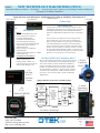
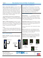
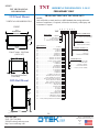
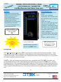
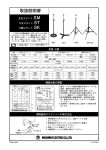
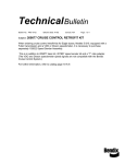
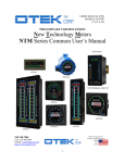
NEW TECHNOLOGY METERS™ MASTER CATALOG October 15, 2015 NEW NTM™ SERIES ( )= Model Number (-N) • CURRENT LOOP POWERED • A. C. SIGNAL POWERED • EXTERNALLY POWERED • BAR-METERS • CONTROLLERS • TRANSMITTERS (TNT) Features: *Input Fail Alarm *Isolated Serial I/O & Flash Memory *1-4 Channels *>30 Input Signals *Only <80mW/Channel *20 Housings *Nuclear, Mil-Spec, Industrial Grades (-9) INDEX: The Housings, Features & Description...............Pages 1 & 2 The New Technology...................................................Page 1 What Can You Do With It?..........................................Page 3 General Option Descriptions...................................Pages 4-6 General Specifications.................................................Page 7 Input Signal Specifications......................................Pages 7-8 Part Number Configuration Rules & Chart..................Page 9 Ordering Information..........................................Pages 10-11 Mechanical and Mounting..................................Pages 13-17 The Transmitter New Technology (TNT)...........Pages 18-19 The New Technology Transmitter (NTT)..........Pages 20-21 Explosion Proof Transmitter/Controller (NTM-X)...Page 22 New Technology Award.............................................Page 23 THE CHOICES: Loop Powered Display: 18 Models A.C. Signal Powered Display: 18 Models Externally Powered (~30 Signal Inputs) Displays & Controllers: 18 Models Transmitter: 4-20mA (~30 Signal Inputs): 3 Models (TNT, NTT & NTM-X) NEED COUNTERS/TIMERS? See our UPM (Universal Panel Meter) Coming soon! (-L) Watch 1 minute video: http://youtu.be/WXi970VXIzM 520-748-7900 FAX: 520-790-2808 E-MAIL:[email protected] http://www.otekcorp.com 4016 E. TENNESSEE ST. TUCSON, AZ. 85714 U.S.A. SINCE 1974 MADE IN USA NEW TECHNOLOGY BAR-METERS (ONLY) NTM™ *Dimensions Shown are Bezels *All models ( ) share the same aware winning award winning Firmware & Hardware *See page 2 for Meter/Controllers LOOP/SIGNAL & EXTERNALLY POWERED PATENTED (& PENDING) TECHNOLOGY ( )=Model Number (-L) 2.9x1.5” (-P) 6.6x1.4” -L +L -L DESCRIPTION: Analog meters have been very useful and reliable in some undemanding applications since invented in 1893, but can not equal digital age technology where HMI (Human-Machine Interface) or MMI (Machine-Machine Interface) are indispensable. +L BENEFITS: Meters: *Replace Analog Meter Pin for Pin *No rewiring or power required *No Stuck Needle/Guessing Forty years after inventing the world’s first loop powered *No Recalibration/Maintenance meter, OTEK brings you its new space-age technology to *No Shock/Vibration Sensitivity help you remain competitive by lowering your maintenance *Auto Tri-Color Bar & Digital Display costs and eliminating the uncertainty of the analog meters. *Signal Failure Detect & Alarm This new technology avoids the operator’s mistrust on stuck *Isolated Serial I/O needles, which is to blame for countless accidents in nuclear, *Remote Display for Scada/DCS aircraft, shipboard and industrial tragedies. It allows the user *Self Diagnostics to communicate directly from the process to the DCS/SCADA*Math Functions-Polynomials, X-Y Tables whether it’s across the street or across the world! *Lifetime Warranty Controllers and Transmitters: +L *All of the above, plus: How Does OTEK’s New Technology Differ? *Relays/Transistors Out We use: ultra-efficient (approaching O LED) LEDs, nanotech- (-X) 4x4 *Analog Output (4-20mA, etc.) nology ASIC, high efficiency power management techniques, Explosion *Universal Power Input (DC & AC) state of the art SV&V (software Verification & Validation) *Ethernet-μSD Memory Card software, monolithic transformers for greater accuracy and Proof isolation, our patented loop power technique, signal failure detection-alarming, patented A.C. signal powering technique, (-F) 16 bit ASIC DAC with galvanic isolation and opto-isolated relay drivers. We also offer OTEK’s exclusive LIFETIME Flat Pack WARRANTY! -L +L 2x3x1/2” No Panel Cut-out NEW TECHNOLOGY SERIES BLOCK DIAGRAM/CHANNEL (-D) 3 1/2” ANALOG METER CASE I V IN A IN CURRENT LOOP (LOOP POWER) AC/DC V, A,W, Hz (SIGNAL POWER) • DISPLAYS, CPU, SIGNAL DETECT, KEEP ALIVE, ISOLATORS FOR ALARMS, SERIAL I/O, PWM, ZERO/SPAN SIGNAL CONDITIONERS REL AYS O.C.T ANALOG OUT ETHERNET USB/485 FLASH MEMORY O.C. T. (4) RELAYS (4) 4-20mA OUT (1) 4-20mA Transmitters TNT or NTT +L 30V OUT (1) RS485 USB/ ETHERNET RS 485 (EXTERNAL POWER) USB -L -L -L +L CONTROLLER/DISPLAY ONLY -L +L (-S) 6 x1” Current Loop 5-32 VDC 90-265 VAC POWER SUPPLY POWER INPUT DISPLAY ONLY Two Wire Current loop -2520-748-7900 FAX: 520-790-2808 E-MAIL:[email protected] http://www.otekcorp.com 4016 E. TENNESSEE ST. TUCSON, AZ. 85714 U.S.A. SINCE 1974 MADE IN USA NTM™ NEW TECHNOLOGY CONTROLLERS & BAR-METERS *Dimensions Shown are Bezels *All models share the same Firmware & Hardware *See TNT and NTT for Transmitters (Pages 18-21 ) *( )=Model Number (-1) 1.9x5.7” 1 or 2 Channels (-2) 2.84x5.7” 1 or 2 Channels (-4) 11.3x1.4” 1 Channel (-5) 3x6” 1, 2, 3 or 4 Channels (-6) 7x1.4” 1 or 2 Channels (-0) 1/8 DIN 3.8x1.9” 1 Channel (-M) 4” Switchboard 1 Channel (-A) 1/4 DIN: 3.8x3.8” 1, 2 or 3 Channels (-3) 4” Switchboard 1, 2 or 3 Channels (-9) 6x1.74” 1 or 2 Channels (-7): 7.2x2.8” (-8): 6.3x2.8” 1, 2, 3 or 4 Channels (-B) 1/8 DIN 1.9x3.8” 1 Channel (-V) 4.06x2.06” 1 Channel -3520-748-7900 FAX: 520-790-2808 E-MAIL:[email protected] http://www.otekcorp.com 4016 E. TENNESSEE ST. TUCSON, AZ. 85714 U.S.A. SINCE 1974 MADE IN USA THE PRODUCTS NTM™ All New Technology products share the same innovations proven by an independent NQA1 qualifier. The difference between the models is their mechanical features (see Block Diagram and mechanical drawings). Some can only be displays, some can only have 1 channel, some can have relays, DACs, ethernet and flash memory, and some require an external power source. But all products contain the New Technology, which consumes less than 1% of comparable digitals (1080mW for loop/signal powered versions) and approaches the power consumption of analog meters. WHAT CAN YOU DO WITH OTEK’S NEW TECHNOLOGY? Note on Otek’s Powerless™ Technology: If your signal cannot supply mW (~ 3V/3mA), contact us or use external power models. 1. One Channel Models: -0, -4, -B, -D, -F, -L, -M, -N, -P, -S, -V & -X: Implement any math function, X-Y table (25 point), polynomials (9th order), offset, tare, zero, scale, log & anti-logarithmic to affect the unit’s display at will. Some examples are: change the display & data using any combination as commanded by your algorithm, such as +/-/X/÷/√ or set a variable or linearize the display using X-Y tables or polynomials. This works well for odd shape containers. You can also change the reading from ◦F to ◦C or ◦K or compress/expand the display (and data out) using the log and antilog functions. In addition, you can change the factory default alarm pointers and colors or delete them. Zero & Span potentiometers are included for manual adjustment. Note: Models -D and -F only offer internally accessible USB serial I/O for configuration and mathematical functions. Use digit 14 option 9 and specify your custom calibration. OTEK’s New Technology series is only limited by your needs and imagination. Just give us a call at 520-7487900 or email us at sales@ otekcorp.com and give us the challenge to develop the best algorithm for your process. 2. Two Channel Models: -1, -2, -3 and -5 through -9 & -A: Note: Also available in models with 3 or 4 channels. Features include all those of the single channel models and each channel is 100% isolated from each other. In addition, you can add, subtract, multiply, divide, find the square root between channels. You can also use one channel to monitor/control the input signal and the second channel to indicate deviation, differential such as PID, alarm override or one channel setpoint can be used to control another channel function. You can also use one channel as a backup if the other channel becomes disabled or use them as volume & flow (√) monitors/ controllers. The New Technology two channel models are also perfect as REM/RAD indicators/controllers (also see our RPM series with logantilog functions for radiation monitoring). Contact OTEK for algorithms and formulas or any idea you wish to share with our audiences via our Youtube or Facebook page posts. 3. Three Channel Models: -3, -5, -7, -8 and -A: Note: Also available on 4 channel models -5, -7 & -8. Otek’s New Technology three channel models perform all the functions outlined in #1 and #2. Further, one channel can indicate the input variable and the other two channels can be setpoint indicators/controllers (Hi, Hi-Hi, Low and Low-Low limits), or subject the input/ output to any mathematical function or algorithm such as PID or display the input vs. output and derivative, or switch scales when the input reaches a limit/band such as for flow-volume-pressure or temperature. Monitor Volts, Amps and Watts AC or DC or any of 3 variables, including Hertz, lead/lag, power factor, peak/valley or for synchronizing of power lines with the bipolar (center zero) tricolor bargraph. The New Technology series brings Process Automation Control (PAC) within your reach and affordability. These models are compatible with any DCS/SCADA system using their USB/RS485/Ethernet I/O options and allow for ease of interface with wireless systems. 4. Four Channel Models: -5, -7 and -8: The four channel models offer all of the functions outlined in #1, #2 and #3. However, with the additional channel available, the New Technology barmeters rival flatscreens with superior HMI/MMI functionality and ease of viewing/analysis of any combination of 4 variables. For example, Volts/ Amps/Watts/Hertz or temperature/pressure/pH/humidity. The four channel models can also be used to monitor/control the product of the other 3 variables, making them ideal for the petrochemical industry. Data Logging? Some models offer optional μSD memory to record 24/7 anything available via the serial I/O. Maximum capacity (and growing) is 32 GB! REDUNDANT CONTROL: Because all channels are 100% isolated from each other, you can use any multi-channels model as a redundant controller. If you need the “Democratic vote,” algorithm, contact OTEK or see our Model TRC (Triple Redundant Controller). -4520-748-7900 FAX: 520-790-2808 E-MAIL:[email protected] http://www.otekcorp.com 4016 E. TENNESSEE ST. TUCSON, AZ. 85714 U.S.A. SINCE 1974 MADE IN USA NTM™ Description, Notes & Order (See Page 12 For Exclusion/Inclusion Charts) DIGIT 6, GRADE: Industrial Grade (Options 0 or I) is per these published specifications. Grades M and E per agreed specifications. Options E & M typically include an EMI/RFI shield all around and filtered connectors to meet EPRI-TR102323-R3 (requiring ~2” deeper case). OTEK will build to certain nuclear or MIL-Standards but testing and confirmation of compliance, if required, will need to be done by third party and at customer’s expense. Option 0 is 94VO plastic, option “I” is aluminium nickel plated to Mil-Specs. Typical Mil-Specs: 461, 462, 169, 901, 801, RTCA-160, I EEE344, etc. DIGIT 5, SERIAL I/O & MEMORY: Settings: 8N1N, 1200-19,200 Baud, ASCII. Digit 5, Serial I/O: Option 0, USB: Complies 100% with V2.0 and if digit 10, option 1 is selected (USB powered) then digit 5 must be option 0. Note: On models -D and -F, USB is only for configuration and not available for communications (unless customized). Note on USB Connectors: All models with Digit 5, Option 0 have μUSB connector behind the front filter and a standard type “B” on the back. Only connect either/or, not both! M & E grades might require “filter” connectors on back and must be specified. Use Digit 5, Option 9 and contact OTEK. Digit 5, Option 1, RS485: Complies with industry standard and will require 5VDC@<3mA and a terminating 330 Ohm resistor at first and last unit in the BUS. Not available on -D or -F model. Connector: plug-in screw terminal on back. Digit 5, Option 2 Ethernet: Complies with 1- BaseT/100Base-TX RJ45 up to 19,200 Baud. Maximum power consumption is <300mA@5V (1.5W). Only available in selected models. Connector: RJ45 on back. NTM-X: Certified for Class I, Div. 1, Groups B-G; EX & IECex: IM2, Exd1. DIGIT 7, (# CHANNELS): See photographs, Table A and “Ordering Information” for # of channels available, their location and exclusive conditions. Case 0: 1 Channel Case 1: Up to 2 Channels Case 2: Up to 2 Channels Case 3: Up to 3 Channels Case 4: One Channel Case 5: Up to 4 Channels Digit 5, Options 3 & 4: μSD Flash Memory: Internal μSD flash memory with up to 32 gigabytes capacity. You can store selected data at-will via serial command and download it as required. Connector: Same as options 0 or 1. Digit 5, Options 5: IRDA: Note: Only available for housing style “X” (explosion proof). IRDA meets industry standards for infrared data reception. You can access all commands/functions without opening -X in hazardous areas. See our model IR/USB that plugs into your USB port (also see IR/232 for RS232 to IRDA). Connector: Internal USB. Case 6: Up to 2 Channels Case 7: Up to 4 Channels Case 8: Up to 4 Channels Case 9: Up to 2 Channels Case A: Up to 3 Channels Cases B – X: One Channel Case -P can be ordered for horizontal mount (instead of vertical). Use digit 14, option 9 and specify “horizontal.” ABOUT OUR INPUT FAIL DETECTION Only available on Powerless™ models (8th & 9th digits, options 00-14). While in normal operation, we store excess energy and use it to power the NTM if and when the signal fails (post mortem). -5520-748-7900 FAX: 520-790-2808 E-MAIL:[email protected] http://www.otekcorp.com 4016 E. TENNESSEE ST. TUCSON, AZ. 85714 U.S.A. SINCE 1974 MADE IN USA NTM™ The Powerful Powerless™ Industrial Grade Common Electrical Specifications Input & Display: See Below For Input Signals: *A/D: Accuracy, Linearity & Resolution: +/- 0.05% of F.S. 12 Bits, Conversion Rate: 40/sec, Averaging: 0-255, zero, span, offset, tare, math functions and 25 point X-Y tables & polynomials. *Bargraph: 51 Automatic Tricolor (R/Y/G) Segments *Digits: Four Full Digits (9.9.9.9 & -1.9.9.9). *Typical Power Consumption of Display: [email protected](>[email protected]); loop power version best at > 8mA. *Temperature Coefficient: +/-50PPM/°C *Operating Temperature: -10 to +60; Storage: -20 to +70°C *CCMR: >90dB@50-60Hz *Isolation: >500VDC to any other I/O & P.S. *Humidity: 5-95% RH non-condensing *Front Panel: NEMA 3. NEMA 4X on request. *Failed Signal Detect: ~ 20 seconds after > 1 minute “On” @50% of F.S. Only on loop & signal powered models. Note 1: See page 13 for NTM replacement chart, including environmental specs vs. housing, bar length and digit size. Yes! You can have the NTM powered by the input signal and have controlling outputs such as relays, O.C.T. & analog output! How it works: Your input signal (Digit 8 & 9, options 00-14 only) powers the display, CPU, serial I/O and isolators. Your external power source powers the outputs. Benefit: You have two independent and isolated sources (fail safe). Requirement: Your signal must produce >10mW (current loop, VDC, VAC or AAC) and sustain <4V burden. If not, use external power (options 20-85 on Digits 8 & 9). AC Signal Power & Outputs? Yes, you can have both input options 01-14 (digits 8 & 9) and relays (2 maximum)without external power! Requirements: VAC input must be >90<140VAC, and AAC input must be >3<6 AAC via C.T. Ideal to monitor and control 120VAC mains! Contact OTEK for details. Zero & Span: Since the NTM requires NO recalibration, the zero & span potentiometers are internal. If required, you can change them via the serial port or remove the unit from the housing and adjust. INPUT SIGNAL SPECIFICATIONS (Digits 8 & 9)- See Pages 10 & 11 Note: All ±1 LSD and % full scale range unless noted. Option 00 For Loop Power Only: Option 04, Hertz VAC: Burden: <100mW, Range: >30V<150V & >30<500Hz; Accuracy & Linearity: ±0.2% of F.S. Option 05-14: Same as options 01 through 04 above. Option 00, Loop Powered: Burden: < 4V; Range: 3-26mA; Accuracy & Linearity: ±0.05% of F.S. Options 01 Through 14 for A. C. Signal Powered Only: FUSE IT! Use external 1/2 ASB for volts and 7 ASB for amps. Important Note: C.T. are sensitive and limited to the secondary (output) impedance. OTEK A.C. signal powered products present and input impedance of ~0.2 Ohms (~1v@5A). Make sure your C.T. can drive a >0.3 Ohm load without saturating or losing linearity. Contact Otek for assistance. Best C.T. to use: >100:5 ratio. Option 01, VAC (P.T.): Burden: <100mW; Range: 30-150V/40-100Hz; Accuracy & Linearity: ±0.2% of F.S. Best operating range: 90-150VAC to specifications. Option 02, 5 AMP A.C. (C.T.): Burden: <100mW; Range: .3-5A; Accuracy & Linearity: ±0.2% of F.S. Best operating range to specifications: 1-5 Amps. Option 03, Watts A.C. (C.T. & P.T.): Burden: <100mW, Range: >30<750W/50-60Hz; Accuracy & Linearity: ±0.2% of F.S. at 90-140VAC & 1-5AAC. Worst case: ±3% outside this range. Best operating range to specification: 100-500 Watts. Options 20 through 58 (or multi-channel equivalent): For Externally Powered Only: All input channels have the same specifications unless noted. See options 60-89 for mixed signals. Option 20, 4-20mA: Burden: <25 Ohm (0.5V); Range: 3-26mA; Accuracy & Linearity: ±0.05% of F.S. Options 21 through 24, VDC: Input impedance 1M Ω; Range: Per Option; Accuracy & Linearity: ±0.05% of F.S. Options 25 & 26, mADC: Input impedance Option 25: 50Ω; Option 26: 5Ω; Accuracy & Linearity: ±0.05% of F.S. Option 27, Watts DC (1Vx1A DC): VZin: 1M Ω/AZin: 1.0Ω, 5W; Range: 1W; Accuracy & Linearity: ±0.1% of F.S. Option 28, Watts DC (1Vx1V): VZin: 1M for both inputs; Range: 0-1V; Accuracy & Linearity: ±0.1% of F.S. NOTE: Always use P.T. or C.T. with H.V. Lines (Options 30-34). -6- 520-748-7900 FAX: 520-790-2808 E-MAIL:[email protected] http://www.otekcorp.com 4016 E. TENNESSEE ST. TUCSON, AZ. 85714 U.S.A. SINCE 1974 MADE IN USA NTM™ INPUT SIGNAL SPECIFICATIONS (Digits 8 & 9): Continued Options 30 through 34: VRMS: Zin: 1MΩ; Range; per options; Accuracy & Linearity: ±0.1% of F.S. Options 35-37, Amps RMS: Zin: Option 35 (0.1A): 2Ω; Option 36 (1 A): 0.2Ω; Option 37 (5A): 0.04Ω; Range: Per option; Accuracy & Linearity: ±0.1% of F. S. Option 38: Watts RMS (1Vx1V AC/DC): Zin: 1MΩ for both inputs; Range: 1V RMS; Accuracy & Linearity: ±0.2% of F.S. Note: Always use P.T. & C.T. for options 33, 34, 40, 42, 43 & 44. Option 40, Watts RMS (120VAC P.T. x5AAC C.T.): Zin: 1M for V & 0.04Ω for I; Range: 0-750W; Accuracy & Linearity: ±0.2% of F.S. Note: Shunt resistor (0.04Ω) supplied. Option 41, Hertz (10KHz/5V Logic): Zin: 1M; Range: 30-10KHz; Accuracy & Linearity: ±0.1% of F.S. Option 42, Hertz (120V, 40-100Hz): Zin: 1M; Range: 50-150VC/30-100Hz; Accuracy & Linearity: ±0.1% of F.S. Option 47 & 48, RTD (Continued): For 3 wire, connect -E to -S. For 2 wire, also connect +E to +S. Warning: Max distance to sensor: ~ 300 Feet (100M) or use our TNT or NTT transmitters. Note: Model NTM-D only accepts 2 wire. Note for Options 47-52: You can switch from ◦F to ◦C via serial port or use option 29 and specify. Default: ◦F. Option 50, Type “J” TC: Range: -210 to 760◦C; Colors: red and white; CJC: Included; Accuracy & Linearity: ±2◦C of F.S. Option 51, Type “K” TC: Range: - 270 to 1370◦C; Colors: Yellow and red; CJC: Included; Accuracy & Linearity: ±2◦C of F.S. Option 52, Type “T” TC: Range: -270 to 400◦C; Colors: blue and red; CJC: Included; Accuracy & Linearity: ±2◦C of F.S. Note for Thermocouples (TC): Shorting out the +/-TC terminals will display the ambient temperature of the C.J.C. at the terminals. Option 43, Hertz (240V, 30-100Hz): Zin 1 M; Range: 100-260V/30-100Hz; Accuracy & Linearity: ±0.1% of F.S. Option 53, pH: Range: 0-14.00; Zin: >1015Ω; Temperature compensation: None; Accuracy & Linearity: ±0.05% of F.S. Option 44, Hertz (120V, 500 Hz): Zin: 1 M; Range: 50-150V/300-500Hz; Accuracy & Linearity: ±0.2% of F.S. Option 54, ORP: Range: 0-2000mV; Zin:>109 Ω; Accuracy & Linearity: ±0.05% of F.S. Note on Strain Gage: Specify S-G, sensitivity, range (cal. resistor value) and calibration. Example: 350 Ohms, 2mV/V, 20mV=0-100%. Option 55, % RH: Range: Per sensor; Input Type: 2-3 pF/% Capacitors; Accuracy & Linearity: ±0.05% of F.S. State sensor’s specifications. Options 45, Strain Gage (≥300K<4K Ohm) : Excitation: 4.096V, 50 PPM/C Range: ±300-4K Ω; Accuracy & Linearity: ±0.1% of F.S. Option 56, Resistance Range: 0-10K Ω=0-100%=0100.0; Accuracy & Linearity: ±0.1% of F.S. Ideal for linear transducers. Option 47 & 48, RTD: 47: 100 Ω (PT100); 48: 1K Ω (PT1000); Range: same as RTD; Accuracy & Linearity: ±0.5% of F.S. 2, 3 or 4 wire RTD. Option 58, None: Serial input only as per Digit 5 for remote/display & controller. Options 60-89: For multichannel mixed signals. Same specifications as per options 20 through 56. -7520-748-7900 FAX: 520-790-2808 E-MAIL:[email protected] http://www.otekcorp.com 4016 E. TENNESSEE ST. TUCSON, AZ. 85714 U.S.A. SINCE 1974 MADE IN USA NTM™ Description, Notes & Order (Continued) DIGITS 8 & 9 (INPUT SIGNAL): DIGIT 11 (CONTROL OUTPUTS & BARGRAPH COLORS): See Input Signal Conditioners section (Page 6 & 7) for description and specifications. Digit 11, Control Outputs: Options 1, 3, 5 or 7: Open Collector Transistors (O.C.T.): They are NOT isolated from each other (common emitter) but are isolated between channels and can sink a maximum of 30 mA and sustain a maximum of 30VCE . The O.C.T. are normally used to drive S.S.R. When you order relays (Digit 11, options 2, 4, 6 or 8) we use the O.C.T. to drive the relays. Power required: none. Digit 11, Options 2, 4, 6 or 8: Relays: are S.P.D.T. (1C) and can switch maximum resistive loads of 1 Amp @ 120 VAC or 30 VDC. They include 300V varistors at their contacts. Inductive loads must be attenuated by user. Power required: 150mW@5VDC/relay. Digit 10 (Power Input): Digit 10, Option 0, Powerless™, No Power Required: The Input Fail detect/Alarm (patented) flashes the display “INPT FAIL” () and transmits this serial message for ~20 seconds, after which it will cease. This feature is available in all Powerless™ models. If desired on powered models, use option 9 on Digit 14 and specify “input fail detection.” Signal Fail Requirement: Unit must be “On” for at least 1 minute at >50% of full scale for it to operate. You can change the message via commands. Digit 10, Option 1, USB Powered: Back up Power for signal powered models: Some applications might require “keep alive” power in case the input signal fails in Powerless™ models (signal/loop powered). If you select option 0 on Digit 10 and have a USB connection, the NTM will transmit the distress message “INPT FAIL” until the signal is restored or the USB is disconnected. AUTOMATIC BAR COLORS: Limits/Colors Factory default (% of Full Scale): Also see digit 14. Low-Low Limit (<10%): Red Bar, OCT4/K4 “ON” Low Limit (<20%): Yellow Bar, OCT3/K3 “ON” High Limit (>80%): Yellow Bar, OCT2/K2 “ON” Hi-Hi Limit (>90%): Red Bar, OCT1/K1 “ON” Note: You can switch limits/relays via command. If you don’t use USB and need “keep alive” power, select options 1-4 or 9 on digit 10. The NTM “keep alive” power requirement is <3mA@5VDC. Safe Area (>20<80%): Green bar will follow signal input and if outside the limits, it will change its color to the limit’s color (yellow or red). Digit 10, Option 2, 5VDC: 5VDC is used to drive the relays (<50mA/relay) and/or the DAC via internal isolated 5-30VDC-DC (<200mA). If you order relays and analog out, you will need ~300mA/channel. This option is also isolated from the input signal. Bargraph or Pointer? Bargraph is by default. You can change it to pointer (one bar) via command or use option 9 on Digit 14 and specify “Pointer.” See commands in the user’s manual to customize your bargraph colors. Digit 10, Option 3, 7-32VDC: Same as option 2 but with wide input range of 7-32VDC. Efficiency: >80%. For other configurations, use option 9 on Digit 14 (field configurable). Max power consumption per relay: 50mA@5VDC (0.25W). See Digit 14. Digit 10, Option 4, 90-265VAC: This option accepts 5060Hz. For 100-300VDC or 400 Hz, use Digit 10, option 9 and specify. Efficiency: >80%. Conditions: If Digit 4 = F (flat pack) then Digit 10 must be Options 0, 2, 3 or 9 (custom). If Digit 10 = 1 (USB Power) then Digit 5 (Serial) must be Option 0 (USB). External Control: You can control the O.C.T./Relays via the serial port with simple commands. They don’t have to be assigned to the bar colors/set points, but are by default. Notes: 1. Digit 11 is governed by Digit 7 (# of Channels) & Digit 4 (Housing). -8520-748-7900 FAX: 520-790-2808 E-MAIL:[email protected] http://www.otekcorp.com 4016 E. TENNESSEE ST. TUCSON, AZ. 85714 U.S.A. SINCE 1974 MADE IN USA Description, Notes & Order (Continued) NTM™ DIGIT 12 (ANALOG /POWER OUTPUT): DIGIT 14 (RANGE/CALIBRATION): Digit 12, Analog Output, Options 1, 3, 5 or 7: This isolated output is factory set to follow the input (0-F.S. in=4-20 out) but can also be set for other outputs such as external 10K Ohm potentiometer (2-22mA out) or 0-0.1VDC=.420mA out; or it can be serially controlled by simple commands via the serial port. For other outputs, use option 9 and specify, including reverse scale (4-20=20-4), bipolar and PID. Power consumption: 200mA@5VDC (1W). Accuracy & linearity: ±0.5% of full scale. 0=Factory Default: 0-Full Scale Input=0-100% bar and 0-100.0 digits. Colors: <10>90%: Red; <20>80%: Yellow; >20<80%: Green. Use Option 9 (custom) and contact Otek. Also see Control Outputs (Digit 11). Bargraph Default: 0-Full scale=0-100%. You can program it for single pointer, or three or five bars via the serial port. Analog Output External Control (Use Option 9 and specify): A) 0-100mVDC in=4-20mA out; B) 0-10K Ohm in=4-20mA out; C) Use options 58, 68, 78 or 88 and control it via serial port. Digit 12, 30 VDC Out, Options 2, 4, 6 or 8: Use this option to power your 4-20mA transmitter or other transducer. Maximum current is 25mADC. It’s isolated and is the same power source we use for options 1, 3, 5 and 7. Power consumption: 200mA@5VDC (1W)/channel. Notes: 1. This digit 12 is governed by digits 4 (Housing) & 7 (# of Channels). Reason: Digit 12 cannot have more outputs than input channels (Digit 7), which is governed by Digit 4 (Housings). OTHER IMPORTANT DATA: Math Functions: +, -, x, ÷, √, Polynomials to 9th order, 25 Point X-Y table, zero, offset, span and tare. You can add, subtract, multiply, divide (etc.) one channel to/from another channel and display the result in the other channel (i.e. V (Ch.1)xA(Ch.2)=W(Ch.3). Signal Failure Alarm: Requires approximately 1 minute of normal (mid-scale) operation for it to alarm the display and output the serial data after the signal (Powerless ™) has ceased (post- mortem). Serial I/O: Setting: 8N1N, 1200-19,200 BAUD, 8 Character Address PID: Programmable (best with >dual channel models) automatic or manual with external 10K Ohm potentiometer (option 56). See models TNT & NTT for dedicated 4-20mA transmitters (same technology). DIGIT 13 (SCALE PLATE): High Quality: No matter their size or number of channels all use the same (SV & V) firmware, hardware and commands. No matter their grade (Industrial, Mil-Spec, Nuclear) they all carry a lifetime warranty. Digit 13, Scale Plate: Option 0 is a standard scale plate that reads 0-100%. Use option 9 for custom printing and contact Otek. Standard Scale 0-100% ◄ Example of Custom Scale (-M) 4” Switchboard 1 Channel (1/2” Long Needles) ► -9520-748-7900 FAX: 520-790-2808 E-MAIL:[email protected] http://www.otekcorp.com Single Bar Pointer Triple Bar Pointer Quintuple Bar Pointer 4016 E. TENNESSEE ST. TUCSON, AZ. 85714 U.S.A. SINCE 1974 MADE IN USA NTM™ NEW TECHNOLOGY SERIES ORDERING INFORMATION 10-15-15 Notes: 1. For multichannel mixed signal of any signal listed or not listed, use option 09, 29, 59, 69, 79 or 89 and specify for quotation by OTEK. 2. Part number is governed by inter-digit exclusivity (“Must” & “Exclusivity”) tables on page 12 or use our configurator at: http://www.otekcorp.com/configurator/nts/. 3. Please refer to option descriptions/conditions on pages 5-9 before selecting. N T M - 4 5 6 7 - 8 9 10 0.....1 Ch...3.8x1.9”....1/8 DIN Horizontal Plastic or Metal 1......1 or 2 Ch..................................5.7x1.9” Metal 2......1 or 2 Ch................................5.7x2.84” Metal 3......1, 2 or 3 Ch..............4” ANSI Swbd, Plastic or Metal 4......1 Ch..........................1.4x11” Plastic or Metal 5......1, 2, 3 or 4 Ch................3x6” Plastic or Metal 6......1 or 2 Ch.....................................7x1.4” Metal 7......1, 2, 3 or 4 Ch..........................7.2x2.8” Metal 8......1, 2, 3 or 4 Ch..........................6.3x2.8” Metal DIGIT 4 9......1 or 2 Ch...................6x1.74” Plastic or Metal A......1, 2 or 3 Ch..........3.8x3.8” 1/4 DIN Plastic or Metal SCALE PLATE 0.................Standard (0-100%) 9.......Custom (Contact OTEK) D.....1 Ch.........3 1/2” Barrel Analog Meter Plastic F......1 Ch..............................2x3” Flat Pack Plastic L.....1 Ch........................2.9x1.5” Plastic or Metal M.....1 Ch.......4” ANSI Swbd, Solid Bar, Plastic or Metal N......1 Ch.....4” ANSI Swbd, Dotted Bar, Plastic or Metal P......1 Ch........................................6.6x1.4” Plastic S......1 Ch.............................................6x1” Plastic V......1 Ch...................................4.06”x2.06” Metal X.....1 Ch....................4x4” Explosion Proof Metal Note 4 DIGIT 7 CONTROL OUTPUTS 0...........................................None 1....CH. 1.....................O.C.T. (4) 2....CH. 1.....................Relays (4) 3....CH. 1 & 2..............O.C.T. (8) 4....CH. 1 & 2..............Relays (8) 5....CH. 1, 2 & 3........O.C.T. (12) 6....CH. 1, 2 & 3........Relays (12) 7....CH. 1, 2, 3 & 4.....O.C.T. (16) 8....CH. 1, 2, 3 & 4.....Relays (16) 9...........Custom (Contact OTEK) SERIAL I/O 0............................................USB 1.........................................RS485 2......................................Ethernet 3................USB & μSD Memory 4..............RS485 & μSD Memory 5.........................IRDA (-X Only) 9............Custom (Contact OTEK) POWER INPUT 0..........Powerless™ (No Power) 1......................Non-Isolated USB 2...........................Isolated 5VDC 3......................Isolated 7-32VDC 4...................Isolated 90-265VAC 9..........Custom (Contact OTEK) GRADE 0..........................................Industrial & Plastic I............................................Industrial & Metal M....To Mil-Spec & Metal (Contact OTEK) E.......To EPRI-Nuclear & Metal (Contact OTEK) 9...........................Custom (Contact OTEK) DIGIT 12 DIGIT 11 DIGIT 10 INPUT SIGNAL DIGIT 8 & 9 See Page 11 and enter option number for Digits 8 & 9. # OF CHANNELS (6) 1......................................One 2......................................Two 3....................................Three 4.......................................Four 9......Custom (Contact OTEK) Example of Good Part Number: NTM-500-480-488-00 Notes (Continued): 4. Grades E, M & 9 might require an N.R.E. fee. -10520-748-7900 FAX: 520-790-2808 E-MAIL:[email protected] http://www.otekcorp.com DIGIT 14 DIGIT 13 ANALOG/POWER OUTPUT 0................................................None 1....CH. 1........................4-20mA Out 2....CH. 1..............................30V Out 3....CH. 1 & 2................4-20mA Out 4....CH. 1 & 2.......................30V Out 5....CH. 1, 2 & 3............4-20mA Out 6....CH. 1, 2 & 3...................30V Out 7....CH. 1, 2, 3 & 4........4-20mA Out 8....CH. 1,2, 3 & 4................30V Out 9..................Custom (Contact OTEK) B.....1 Ch...1.9x3.8”.........1/8 DIN Vertical Plastic or Metal DIGIT 6 11 12 13 14 RANGE/CALIBRATION 0..................................Standard 9........Custom (Contact OTEK) HOUSING (BEZEL DIMENSION & MATERIAL) DIGIT 5 - Example of Bad Part Number: NTM-300-480-488-00* *Red Numbers are conflicting options) 4016 E. TENNESSEE ST. TUCSON, AZ. 85714 U.S.A. SINCE 1974 MADE IN USA NTM™ NEW TECHNOLOGY DIGITS 8 & 9 ORDERING INFORMATION 10-15-15 INPUT SIGNAL 1 2 N T 3 M - 4 5 6 7 8 - FOR LOOP/SIGNAL POWERED ONLY (2) 00.....................................4-20mA, All Channels=Input, Loop Power 01...........................................Volts A.C., All Channels, Signal Power 02.......................................5 Amps A.C., All Channels, Signal Power 03..........................................Watts A.C., All Channels, Signal Power 04.......................................Hertz A.C.V., All Channels, Signal Power 05......Mixed 2 Channel...........Ch. 1: VAC; Ch. 2: AAC ,Signal Power 06......Mixed 2 Channel...........Ch. 1: VAC; Ch. 2 WAC, Signal Power 07......Mixed 2 Channel...............Ch. 1: VAC; Ch. 2: Hz, Signal Power 08......Mixed 2 Channel...........Ch.1: AAC; Ch. 2: WAC, Signal Power 09..................................................................Custom (Contact OTEK) 10......Mixed 3 Channel....... Ch. 1: V; Ch. 2: A; Ch. 3: W, Signal Power 11......Mixed 3 Channel.......Ch. 1:V; Ch. 2: A; Ch. 3: Hz, Signal Power 12......Mixed 3 Channel.......Ch. 1: V; Ch. 2: W; Ch. 3: Hz, Signal Power 13......Mixed 3 Channel.......Ch. 1: A;Ch. 2: W; Ch. 3: Hz, Signal Power 14.......Mixed 4 Channel.....Ch. 1: V; Ch. 2: A; Ch. 3: W; Ch. 4: Hz, Signal Power FOR TNT & EXTERNAL POWER ONLY (1-4 Ch.) (3) mAll Channels Same Input) 21...............................................100mV DC F.S. 22.......................................................1VDC F.S 23.....................................................10VDC F.S. 24..................................................100VDC F. S. 25.................................................10mADC F. S. 26................................................100mADC F.S. 27...................................Watts DC (1Vx1A) F.S. 28...................................Watts DC (1Vx1V) F.S. 29...............................Custom (Contact OTEK) 30...............................................0.1V RMS F. S. 31...................................................1V RMS F.S. 32.................................................10V RMS F.S. 33..............................................150V RMS F.S. 34.............................................250 V RMS F.S. 35...............................................0.1A RMS F.S. 36..................................................1A RMS F.S. 37...................................................5A RMS F.S. 38...............................W RMS (1Vx1VAC) F.S. 40..........................W RMS (120Vx5A AC) F. S. 41.........................Hertz (10KHz/5V Logic) F.S. 42....................Hertz (120VAC/40-100 Hz) F.S. 43....................Hertz (240VAC/30-100 Hz) F.S. 44..........................Hertz (120VAC/500 Hz) F.S. 45........................Strain-Gage (≥300<4K Ohm) 47..................................................RTD (PT100) 48................................................RTD (PT1000) 50.....................................................TC (Type J) 51....................................................TC (Type K) 52....................................................TC (Type T) 53...................................................pH (0-14.00) 54.......................................ORP (0-2000mVDC) 55...................................% RH (Specify Sensor) 56......................................Resistance (0-10K None (Serial Input Remote Meter) 9 10 - 11 12 13 14 MIXED INPUT SIGNALS (2 CHANNELS) {5} 60..............................Ch.1: 1V; Ch.2 1A (.2 Ω) DC 61..........................Ch.1: 10V; Ch.2: 1A (.2 Ω) DC 62........................Ch.1: 100V; Ch.2: 1A (.2 Ω) DC 63...................Ch.1: 100V; Ch.2: 50mV (0.02 Ω) DC 64...................Ch.1: 150V; Ch.2: 5A (.04 Ω) RMS 65....................Ch.1: 250V; Ch.2: 5A (.04Ω) RMS 66.....Ch.1: 150V; Ch.2: 100Hz (120 V Line) RMS 67.....Ch.1: 250V; Ch.2: 100 Hz (240V Line) RMS 68.......................................None, Serial Input Only 69......................................Custom (Contact OTEK) MIXED INPUT SIGNALS (3 CHANNELS) {5} 70.....................Ch.1: 1V; Ch.2: 1A (.2 Ω); Ch.3: W DC 71...................Ch.1: 10V; Ch.2: 1A (.2 Ω); Ch.3: W DC 72..................Ch.1: 100V; Ch.2: 1A (.2 Ω); Ch.3: W DC 73.............Ch.1: 100V; Ch.2: 50mV (0.02 Ω); Ch.3: W DC 74.............Ch.1: 150V; Ch.2: 5A (.04 Ω); Ch.3: W RMS 75.............Ch.1: 250V; Ch.2: 5A (.04Ω); Ch.3: W RMS 76.....Ch.1: 150V; Ch. 2: 5A (.04Ω); Ch.3: 100Hz RMS 77....Ch.1: 250V; Ch. 2: 5A (.04Ω); Ch.3: 100 Hz RMS 78..............................................None, Serial Input Only 79.............................................Custom (Contact OTEK) MIXED INPUT SIGNALS (4 CHANNELS) {5} 80......Ch.1: 150V; Ch.2: 5A (.04 Ω); Ch.3: W; Ch.4: 100Hz RMS 81.....Ch.1: 250V; Ch. 2: 5A (.04Ω); Ch.3: W; Ch.4: 100 Hz RMS 82.....Ch.1: 120V; Ch. 2: 5A (.04Ω); Ch.3: W; Ch.4: 500 Hz RMS 83.....Ch.1: 250V; Ch. 2: 5A (.04Ω): Ch.3: W; Ch.4: 500 Hz RMS 88...............................................................None, Serial Input Only 89..............................................................Custom (Contact OTEK) NOTES: 1. # of input channels is governed by Digit 7 (Page 11). 2. Option 00 only for loop powered (Digit 10, option 0). 3. Options 20 thru 58 available for all models except NTM-D; options 60 thru 69 only for models with 2+ channels (digit 7, options 2-4); Options 70-79 only for models with 3+ channels (digit 7, options 3 or 4); options 80-89 only for digit 7, option 4. 4. Options 20-89 only for externally powered models (Digit 10, options 1-9). 5. 50mV shunt not included. 6. On NTM-P for horizontal munt or edgecard connector use option 9 on Digit 7 and specify. -11520-748-7900 FAX: 520-790-2808 E-MAIL:[email protected] http://www.otekcorp.com 4016 E. TENNESSEE ST. TUCSON, AZ. 85714 U.S.A. SINCE 1974 MADE IN USA NOTE: If you use our award winning Configurator, you can ignore this page! Table A NTM™ METERS/CONTROLLER MODELS OPTIONS THAT MUST BE SELECTED VS. CASE OPTION # (DIGIT 4) MODEL/ BEZEL SIZE (DIGIT 4) SERIAL I/O (DIGIT 5) GRADE (DIGIT 6) # OF INPUT CHANNELS (DIGIT 7) INPUT SIGNAL (DIGITS 8 & 9) POWER INPUT (DIGIT 10) CONTROL OUTPUTS (DIGIT 11) ANALOG OUTPUT/ POWER (DIGIT 12) -0 0 THRU 4 0, I M, E 1 00 THRU 04 or 20 THRU 58 0 THRU 4 0 THRU 2 0 THRU 2 -1 0 THRU 4 I, M, E 1 OR 2 00 THRU 08 OR 20-68 0 THRU 4 0 THRU 4 0 THRU 4 -2 0 THRU 4 I, M, E 1 OR 2 00 THRU 08 OR 20-68 0 THRU 4 0 THRU 4 0 THRU 4 -3 0 THRU 4 0, I, M, E 1 THRU 3 00 THRU 13 OR 20-78 0 THRU 4 0 THRU 6 0 THRU 6 -4 0 THRU 4 0, I, M, E 1 00 THRU 04, 20 THRU 58 0 THRU 4 0 THRU 2 O THRU 2 -5 0 THRU 4 0, I, M, E 1 THRU 4 00-88 0 THRU 4 0 THRU 8 0 THRU 8 -6 0 THRU 4 I, M, E 1, 2 00 THRU 08, 20 THRU 68 0 THRU 4 0 THRU 4 0 THRU 4 -7 0 THRU 4 I, M, E 1 THRU 4 00 THRU 88 0 THRU 4 0 THRU 8 0 THRU 8 -8 0 THRU 4 I, M, E 1 THRU 4 00 THRU 88 0 THRU 4 0 THRU 8 0 THRU 8 -9 0 THRU 4 0, I, M, E 1, 2, 00-08, 20 THRU 68 0 THRU 4 0 THRU 4 0 THRU 4 -A 0 THRU 4 0, I, M, E 1 THRU 3 00 THRU 13, 20 THRU 78 0 THRU 4 0 THRU 6 0 THRU 6 -B 0 THRU 4 O, I, M, E 1 00 THRU 04 or 20 THRU 58 0 THRU 4 0 THRU 2 0 THRU 2 -M 0 THRU 4 0, I, M, E 1 00 THRU 04, 20 THRU 58 0 THRU 4 0 THRU 2 0 THRU 2 -N 0 THRU 4 0, I, M, E 1 00 THRU 04, 20 THRU 58 0 THRU 4 0 THRU 2 0 THRU 2 -P 0, 1 0 1 00 THRU 04, 20 THRU 58 0 THRU 4 0 THRU 2 0 THRU 2 -S 0, 1 0 1 00 THRU -04, 20 THRU 58 0 THRU 4 0 THRU 2 0 THRU 2 -V 0 THRU 4 I, M, E 1 00 THRU 04, 20-58 0 THRU 4 0 THRU 2 0 THRU 2 -X 0, 1, 3 THRU 6 I, M, E 1 20 THRU 58 0 THRU 4 0 THRU 2 0 THRU 2 NOTE: Our NTM-X is CE approved for explosive atmospheres (IECex)! METERS (DISPLAY ONLY MODELS) OPTIONS THAT MUST BE SELECTED VS. CASE OPTION # (DIGIT 4) MODEL/ BEZEL SIZE (DIGIT 4) SERIAL I/O (DIGIT 5) GRADE (DIGIT 6) # OF INPUT CHANNELS (DIGIT 7) INPUT SIGNAL (DIGITS 8 & 9) POWER INPUT (DIGIT 10) CONTROL OUTPUTS (DIGIT 11) ANALOG OUTPUT/ POWER (DIGIT 12) -D 0 0 1 00 THRU 04, 20 THRU 58 0 THRU 4 0 0 -F 0 0 1 00, 01 & 04, 20 THRU 58 0 THRU 3 0 0 -L 0, 1 0, I, M, E 1 00 THRU 04, 20 THRU 58 0 THRU 4 0 0 EXCLUSIVITY RULES: DIGIT 4 (HOUSING): If options 1, 2, 6, 7, 8 or X (metal), then digit 6 (Grade) must be I, M or E; if options D, F, P or S, then dig. 6 must be 0 (plastic); if option F, then dig 10 (Power) must be options 0-3, and digits 5, 6, 11 & 12 (Outputs) must be option 0. DIGIT 5 (SERIAL I/O): If option 2, 3 or 4, then digit 4 (Case) must be 0-B, M or N; if options 5 or 6 (IRDA), then digit 4 (Case) must be X; if options 2, 3 or 4, then digit 10 (Power) must be 2, 3 or 4. DIGIT 6 (GRADE): If option 0 (plastic), then digit 4 (Case) must be 0, 3, 4, 5, 9, A, B, D, F, L, M, N, P or S; if option I, then digit 4 must be options 0-9, A, M, N or X. DIGIT 7 (# OF CHANNELS): Option 1: no exceptions; if option 2, then digit 4 (Case) must be options 1-3, or 5-A; if option 3, then digit 4 (Case) must be options 3, 5, 7, 8 or A; if option 4, then digit 4 (Case) must be options 5, 7 or 8. DIGIT 8 & 9 (INPUT SIGNAL): If options 00-04 or 20-58 (1 Ch.), then digit 4 (Case) can be any option; if option 05-08 or 60-69 (2 Ch.), then digit 4 (Case) must be options 1-3, 5-A; if options 70-79 (3 Ch.), then digit 4 (Case) must be options 3, 5, 7, 8 or A; if options 80-89 (4 Ch.), then digit 4 (case) must be options 5, 7 or 8; if options 00-14, then digits 10, 11 & 12 (Power & Outputs) must be option 0; if options 20-89, then digit 10 (Power) must be options 1-4. DIGIT 10 (POWER INPUT): If option 0 (Powerless™) then digit 5 (Serial) must be options 0 or 1 and digits 8 & 9 (Input Signal) must be options 00 through 14 (Powerless™); if option 1 (USB), then digit 5 (Serial) must be option 0; if option 4, then digit 4 (Case) cannot be option F (Flat Pack). DIGIT 11 OR DIGIT 12 (CONTROL OR ANALOG/POWER OUT): If option 0, no restrictions; if options 1 or 2 (1 Ch.), then digit 4 (Case) must be options 0-B, M, N, P or X; if option 3 or 4 (2 Ch.), then digit 4 (Case) must be options 1, 2, 3 or 5-A; if options 5 or 6 (3 Ch.), then digit 4 (Case) must be options 3, 5, 7, 8 or A; if options 7 or 8 (4 Ch.), then digit 4 (Case) must be options 5, 7 or 8. See pages 19-22 for dedicated 4-20mA transmitters. -12520-748-7900 FAX: 520-790-2808 E-MAIL:[email protected] http://www.otekcorp.com 4016 E. TENNESSEE ST. TUCSON, AZ. 85714 U.S.A. SINCE 1974 MADE IN USA NEW TECHNOLOGY METER REPLACEMENT CHART NTM™ METERS & CONTROLLERS Housing (Digit 4) ( )=Bezel Size REPLACES ANALOG OR DIGITALS *All Models NEMA 3 NEMA 4X on Request BAR LENGTH/ DIGIT SIZE NTMOption 0: (3.8x1.9”), 1/8 DIN Plastic or Metal, Horizontal 2.5”/.4” Any 1/8 DIN DPM Horizontal Option 1: (5.7x1.9”), Metal 4”/.4” Sigma-VMI-Dixson, Otek’s HIQ121 Option 2: (5.7x2.84”), Metal 4”/.4” Sigma-VMI-Dixson, Otek’s HIQ122 Option 3: (4” ANSI Switchboard), Plastic or Metal 6.5”/.3 &.25” Option 4: (1.4”x11”), Plastic or Metal 8”/.3” DB40, Weschler BF6400, Dixson, 4” ANSI Switchboard Chessel’s 700, Any 8” Bargraph Option 5: (3x6”), Plastic or Metal 4”/.3” Any 3x6” Meter Option 6: (7x1.4”), Metal 4”/.3” Bailey RY, Dixson SH101 Option 7: (7.2x2.8”), Metal 4”/.3” Bailey 775, Foxboro 257, Otek HIQ117 Option 8: (6.3x2.8”), Metal 4”/.3” Bailey 775, Foxboro 257, Otek HIQ118 Option 9: (6x1.74”), Plastic or Metal 4”/.3” GE180, Yokogawa 180, Dixson, Weschler Option A: (3.8x3.8”), 1/4 DIN Plastic or Metal 2.5”/.4” Any 1/4 DIN (96x96mm) Meter Option B: (3.8x1.9”), 1/8 DIN Plastic or Metal, Vertical 2.5”/.4” Any 1/8 DIN (48x96mm) Meter, Vertical Option D: (3 1/2”), Barrel Analog Meter Plastic Option F: (2x3”), Flat Pack Plastic 3”/.4” Any Analog Meter Case 3 1/2” Barrel 3”/.3” Any Otek “Flat Pack” 516 through 528, 400-414 & FPM Option L: (2.9x1.5”), Plastic or Metal 2.5”/.25” Otek’s LPM, LPE, NPM, Velonex Option M: (ANSI Switchboard .4”), Plastic or Metal 6.5”/.6” DB40, Weschler, Dixson, Otek’s HIQTBS & HIQ123 Option N: (ANSI Switchboard .4”), Plastic or Metal 6.5”/.6” DB40, Weschler, Dixson, Otek’s HIQ124 & HIQTBE Option P: (6.6x1.4”), Plastic 4”/.25” Dixson BE 051/101, Sigma, VMI, Otek’s HIQ101 Option S: (6x1”), Plastic 2.5”/.25” Otek’s HIQSLIM 1, 2 or 3 Option V: (4.06x2.06”), Metal, Vertical 2.5”/.4” Scientech/Sigma/VMI/Versatile 9200 Series, Vertical Option X: (4x4”), Class I, Div. 1, E.P., Metal 3”/.3” Any Explosion Proof Meter, Otek’s LPX TRANSMITTERS TNT: Transmitter Only (1.9x3.8”), Plastic/Metal 4”/.25” N/A NTT: Transmitter Only (3x6”), Plastic/Metal 4”/.25” N/A MAX CONTROL OUTPUT LIMITATIONS SINGLE CHANNEL MODELS MULTICHANNEL MODELS MODEL # OF CH. RELAYS/O.C.T. 4-20mA/30 MODEL RELAYS/O.C.T. 4-20mA/30 4/4 1/1 0 1 4/4 1/1 B 1 1-2 8/8 2/2 D NONE NONE 2/2 F NONE NONE NONE NONE 2 1-2 8/8 3 1-3 12/12 3/3 L 4 1 4/4 1/1 M 4/4 1/1 N 4/4 1/1 5 1-4 16/16 4/4 6 1-2 8/8 2/2 P 2/4 1/1 4/4 S 2/4 1/1 V 4/4 1/1 7 1-4 16/16 8 1-4 16/16 4/4 9 1-2 8/8 2/2 X 2/4 1/1 3/3 TNT (XMTR) 2/4 1/1 NTT (XMTR) NONE 1/1 A 1-3 12/12 -13520-748-7900 FAX: 520-790-2808 E-MAIL:[email protected] http://www.otekcorp.com 4016 E. TENNESSEE ST. TUCSON, AZ. 85714 U.S.A. SINCE 1974 MADE IN USA NEW TECHNOLOGY MECHANICAL & MOUNTING INFORMATION BY CASE STYLE (Digit 4 & Option #) NTM™ OPTION -0 1/8 DIN 3.8x1.9” Bezel Mechanical OPTION V 4.06x2.06” Bezel Mechanical 2.20 56mm Option -1 5.7x1.9” Metal Bezel Mechanical FRONT VIEW REAR REAR VIEW SIDE VIEW SEE USER’ MANUAL FOR ACTUAL CONNECTIONS PER MODEL CONFIGURATION. NTM-B INDUSTRIAL GRADE (For reference only) SPAN ZERO ST1 ST4: RS485 1: +5 V D.C. 2: D- (B) 3: D+ (A) 4: GROUND SERIAL I/O 1 2 3 4 USB ST4 .2 .5 5mm 12mm PLUG IN SCREW CONNECTORS ST5: 1: CUSTOM INPUT 2: -LOOP/0V OUT 3: +LOOP/30V OUT (16-26 GA WIRES) Panel Cutout: 46x92mm (1.85x3.62”) 1 2 3 4 5 6 7 8 9 10 1112 SERIAL I/O 12 34 1 2 3 ST1A 2 3.45 87.6mm 3 4 4 3 ST3B 2 1 ST3 12 11 10 9 8 7 ST2B 6 5 4 3 2 1 Panel Cutout: >3.5”<4.0” H x >1.8”<2” W 12 1.78 45.2mm ST5 SPAN 5.400 5.700 ZERO 1.75 44.5mm ST3 ST2 USB 1 ST2 1 2 3 4 5 6 7 8 9 10 11 12 1 2 SPAN ZERO ST1 1 2 3 DAC/30V OUT REAR 12 34 ST5 1 2 3 4 FRONT SIDE 3.55 90.2mm SPAN ZERO 1 2 ST3A 3 4 ST4A 1 2 ST5A 1 4 ST1B 3 SERIAL I/O 2 2 3 1 4 DAC/30V OUT ST4 1 2 3 4 ST2A 5 6 7 8 9 10 11 12 VARIES WITH OPTIONS: >1<8” FRONT 4.30” TO MOUNTING BRACKETS 103mm (4.06”) 91.4mm (3.6”) 48mm (1.9”) (0.6”) 15 mm VARIES WITH OPTIONS: >1<8” 12mm (0.5”) PLUG IN SCREW CONNECTS (16-26 GA WIRES) 96mm (3.78”) 1.65" 1.90" 03mm 4.06”) INDUSTRIAL PANEL CUT-OUT: 1.67x5.42” NOTE: INDUSTRIAL HAS EURO PLUG CONNECTORS (MIL OR EPRI HAS FILTERED TERMINAL CONNECTORS) DEPTH VARIES WITH OPTION. MAX: 3” 52mm (2.06”) OPTION -2 2.84X5.7” Bezel Mechanical OPTION -3 ANSI 4” Switchboard Mechanical Panel Cutout: 5.42x2.70” Depth: 1” (Display Only 3” (Controller) “XXD” “XXC” 4.38" <1.25" 0.125"R (4 PL.) 4.35" 0.70" 3.375" (85.2MM) SQR. 8-32x1" (4 PL) 3.50"D REAR VIEW FRONT VIEW CONNECTORS SEE USER’ MANUAL FOR ACTUAL CONNECTIONS PER MODEL CONFIGURATION. 4.35" & ADJUSTMENT AREA 3"H X 2.5"W CENTERED 4 CL 1 ST1A 2 3 4 1 2 3 4 5 6 7 8 9 10 11 12 4 3 ST3B 2 1 ST2A 12 11 10 9 8 ST2B 7 6 5 4 3 2 1 ST3A 2 SPAN ZERO FRONT VIEW 5.40” 5.70” 2 1 ST4B SIDE VIEW REAR VIEW F#87TBSME 1. ANSI 4"(3.375") CASE CAN ALSO BE MOUNTED IN 1/4 DIN PANEL CUTOUT. 2. CONNECTORS AND 3.375" STUDS SPACING MEET ANSI39.1 STANDARD FOR SWITCHBOARD METERS. J1 FALLS WITHIN EXISTING "BARREL" CUTOUT. 3. WIRE: 26-16GA 1 3 4 ST4A 1 2 ST5 1 4 2 3 ST1B SERIAL I/O 3 2 4 1 4. SHIELDED VERSIONS WILL EXTEND ~2” BEHIND THE PANEL. 1.70" 5. PLASTIC IS 1” THICK; METAL IS 0.7” THICK. 2.84" -14520-748-7900 FAX: 520-790-2808 E-MAIL:[email protected] http://www.otekcorp.com 4016 E. TENNESSEE ST. TUCSON, AZ. 85714 U.S.A. SINCE 1974 MADE IN USA NEW TECHNOLOGY MECHANICAL & MOUNTING INFORMATION BY CASE STYLE (Digit 4 & Option #) NTM™ OPTION -5 3x6” Bezel Mechanical OPTION -4 11.3x1.4” Bezel Mechanical FRONT VIEW REAR VIEW SIDE VIEW FRONT VIEW CH 1 TYPICAL CONNECTIONS REAR VIEW SIDE VIEW ST1A ST1C CH 3 ZERO SPAN ZERO SPAN 1 2 3 4 CH C 1 2 3 4 CH A ST3A 1 2 SPAN SERIAL I/O ZERO ST1 5.60 6.00 6.00 1 2 3 4 1 2 3 4 ST5 CH A 10.825 11.325 ST1B ST1D 1 2 3 4 CH D CH 2 ZERO SPAN CH 4 0.50 0.50 3.10” CH B 1 2 3 4 ZERO SPAN 2.90” 2.50 3.00 SERIAL I/O USB Mounting: 1. REMOVE FILTER 1 2 3 4 ST5 2. TWIST MOUNTING TABS (2) CLOCKWISE 3. REPLACE FILTER 1.400 0.250 2.812 1.300 PANEL CUT-OUT: 1.34x10.88” PANEL CUT-OUT: 3x5.6” OPTION -6 7x1.4” Bezel Mechanical OPTION -7: 7.2x2.8” Bezel Mechanical TYPICAL CONNECTIONS REAR VIEW REAR VIEW CH 1 CH 3 1 1 ST1C 2 METER/DISPLAY: 1” DEEP CONTROLLER: 3” DEEP ZERO CH A 1 2 3 4 6.25” 3 4 1 2 3 4 ST2C 5 4 3 6 2 ST3D 7 1 8 9 ZERO 10 11 SPAN 12 12 11 SPAN 10 ZERO 9 1 8 7 ST2D ST3C 2 3 6 5.45” SERIAL I/O 7.0” ST1A 2 3 4 ST1A SPAN USB 1 2 3 4 ST5 5 4 3 2 1 CH 2 CH 4 4 ST4C 1 2 ST5 1 2 4 SERIAL I/O 3 3 ST1D 4 2 1 ST1B CH B 1 2 3 4 1 2 3 4 4 3 5 2 ST3B ST2A 6 1 7 ZERO SPAN 8 9 10 11 12 12 11 10 SPAN 9 ZERO 8 7 ST2B 1 ST3A 2 6 3 5 4 4 3 ST4A 1 2 2 1 ST5 1 4 2 3 ST1B SERIAL I/O 2 3 1 4 SPAN ZERO 2.60” 1.35” 1.40” PANEL CUT-OUT: 1.35x6.30” DEPTH: 1” (DISPLAY ONLY) 3” (CONTROLLER) 520-748-7900 FAX: 520-790-2808 E-MAIL:[email protected] http://www.otekcorp.com PANEL CUT-OUT: 2.65x5.50” DEPTH: 1” (DISPLAY ONLY) 2” (CONTROLLER) -154016 E. TENNESSEE ST. TUCSON, AZ. 85714 U.S.A. SINCE 1974 MADE IN USA NTM™ NEW TECHNOLOGY MECHANICAL & MOUNTING INFORMATION BY CASE STYLE (Digit 4 & Option #) OPTION -9: (Industrial) 6x1.74” Bezel Mechanical OPTION -8: 6.3x2.8” Bezel Mechanical REAR VIEW FRONT VIEW REAR VIEW SIDE VIEW ST1A ZERO 1 ST1C 2 3 4 CH 1 CH 3 1 2 3 4 ST2C 5 4 3 6 2 ST3D 7 1 8 9 ZERO 10 11 SPAN 12 12 11 SPAN 10 ZERO 9 1 8 7 ST2D ST3C 2 3 6 4 5 4 ST4C 1 3 2 2 1 ST5 1 2 4 SERIAL I/O 3 3 ST1D 4 2 5.45” CH 2 CH 4 1 1 2 3 4 1 ST1A 2 3 4 ST3 1 2 3 4 4 3 5 2 ST3B ST2A 6 1 7 8 ZERO 9 10 SPAN 11 12 12 11 10 SPAN 9 ZERO 8 7 ST2B 1 ST3A 2 6 3 5 4 4 3 ST4A 1 2 2 1 ST5 1 4 2 3 ST1B SERIAL I/O 2 3 1 4 1 2 5.50” 1 2 3 4 ST5 ST1B CH B 1 2 3 4 ZERO 1” SPAN .75” 1.65” PANEL CUT-OUT: 1.70x5.70” DEPTH VARIES W/OPTIONS. MAX: 3” 2.60” NOTE: DISPLAYS ARE 1” DEEP CONTROLLERS ARE 2.3” DEEP PANEL CUT-OUT: 2.65x5.50” DEPTH: 1” (DISPLAY ONLY) 3” (CONTROLLER) OPTION -9 (EPRI) 6x1.74” Bezel Mechanical CH A SPAN OPTION -A 1/4 DIN: 3.8x3.8” Bezel Mechanical NTM-9 MECHANICAL INFORMATION (EPRI) NTM-A REAR VIEW (SIGNAL POWER MODEL) TYPICAL CONNECTIONS REAR VIEW PANEL CUTOUT: 3.625" X 3.625" (92mm X 92mm) NOTES: 1.) DISPLAY AREA VARIES WITH MODEL # 3.575" SQUARE (92X92mm) SLIDES (2) 1 ST1A 2 3 4 4 3 ST3B 2 1 5.5” ZERO SPAN 12 11 10 9 8 7 ST2B 6 5 4 3 2 1 1 2 3 4 ST2A 5 6 7 8 9 10 11 12 WARNING! H.V. IN THIS SECTION. DO NOT TOUCH MAX PANEL THICKNESS: 3/4" (19mm) ZERO ST1C 1 2 3 4 CH C SPAN ZERO ST1B 1 2 3 4 ST4 CH B SPAN 12 3 4 ZERO USB ST1A SERIAL I/O 1 2 3 4 CH A SPAN SPAN ZERO 1 2 ST3A 3 3.78" SQR. (96X96 mm) 3.00" 0.20" 4 INCLUDING CONNECTORS. ST4A 1 2 4 ST1B ST5A 1 3 SERIAL I/O 2 2 3 1 4 OPTION -B 1/8 DIN VERTICAL 1.9x3.8” Bezel Mechanical .75” FRONT 3” SIDE REAR 2.20 56mm NOTE: DISPLAYS ARE 1” DEEP CONTROLLERS ARE 2.3” DEEP SPAN ZERO ST1 4.3” TO MOUNTING BRACKETS RS485 (ST4): 4. GROUND 3: D+ (A) 2: D- (B) 1: +5 V D.C. SERIAL I/O 1 2 3 4 USB ST4 ST5: 1: CUSTOM INPUT 2: -LOOP/0V OUT 3: +LOOP/30V OUT ST5 1 2 3 DAC/30V OUT 1 2 3 4 ST2 1 2 3 4 5 6 7 8 9 10 11 12 3.55 90.2mm 96mm (3.78”) 96mm (3.78”) 90.2mm (3.55”) ST3 1 2 PANEL CUT-OUT: 1.70x5.70” DEPTH: 3” 520-748-7900 FAX: 520-790-2808 E-MAIL:[email protected] http://www.otekcorp.com 1.78 45.2mm -16- .2 5mm 48mm (1.9”) .5 12mm PLUG IN SCREW CONNECTS (16-26 GA WIRES) 4016 E. TENNESSEE ST. TUCSON, AZ. 85714 U.S.A. SINCE 1974 MADE IN USA NEW TECHNOLOGY MECHANICAL & MOUNTING INFORMATION BY CASE STYLE (Digit 4 & Option #) NTM™ OPTION -D 3 1/2” Analog Meter Case Mechanical SIDE VIEW FRONT VIEW 4-M3 DISPLAY AREA 2.5” Ø 3.26 OPTION -F Flat Pack 2x3” Mechanical CL 0.6 Ø2.71 DISPLAY ZERO OTEK 0.55 1.84 REAR VIEW 1.12 0.40 HOLE DIAMETER: 2.75” MTG. HOLES (4): 0.15” Ø Ø0.15 1 2 OTEK TUCSON,AZ 3 2.24 NOTE: ZERO, SPAN & POST 1/4-28 BRASS (4) 4 NO PANEL CUT-OUT! THE COVER. OPTION -L: 2.9x1.5” Bezel Mechanical TOP VIEW 1.971 10 9 87 Mounting Instructions: 1. Drill a 3/8 - 1/2" diameter hole. 2. Attach supplied double sided tape to back of it. 3. Pass wires through hole. 4. Align and Press NTM-F on panel (that is all!) 5. Don’t pull on wires (26 gage)! SERIAL I/O ARE BEHIND 2.24 2.252 SPAN 0.35 3.26 1.12 OPTIONS -M & -N: ANSI 4” Switchboard Mechanical REAR VIEW PANEL CUT-OUT: 2.750 X 1.310" 6 5 4 3 2 1 1.593 5 78 9 0 0.70" CONNECTORS ST1 0.218 0.150 0 2.710 REAR VIEW 1 2 3 4 5 6 7 8 9 10 1112 1.250 MOUNTING BRACKET 4.35" SIDE VIEW 1.385 1.250 1.075 0.625 3.375" (85.2MM) SQR. 8-32x1" (4 PL) 3.50"D 1.250 16 21 34 4.38" <1.25" 0.125"R (4 PL.) 4.35" MOUNTING BRACKET USB 2.710 APPLY ADHESIVE AGAINST PANEL HERE FRONT VIEW MOUNTING BRACKET & ADJUSTMENT AREA 3"H X 2.5"W CENTERED 4 CL SIDE VIEW REAR VIEW F#87TBSME 1. ANSI 4"(3.375") CASE CAN ALSO BE MOUNTED IN 1/4 DIN PANEL CUTOUT. 2. CONNECTORS AND 3.375" STUDS SPACING MEET ANSI39.1 STANDARD FOR SWITCHBOARD METERS. J1 FALLS WITHIN EXISTING "BARREL" CUTOUT. 3. WIRE: 26-16GA 0.579 0.067 0 4. SHIELDED VERSIONS WILL EXTEND ~2” BEHIND THE PANEL. CONNECTOR: PLUG-IN SCREW TERMINAL 26-18 GA 5. PLASTIC IS 1” THICK; METAL IS 0.7” THICK. -17520-748-7900 FAX: 520-790-2808 E-MAIL:[email protected] http://www.otekcorp.com 4016 E. TENNESSEE ST. TUCSON, AZ. 85714 U.S.A. SINCE 1974 MADE IN USA NEW TECHNOLOGY MECHANICAL & MOUNTING INFORMATION BY CASE STYLE (Digit 4 & Option #) NTM™ OPTION -S: 6 x1” Bezel Mechanical OPTION -P: 6.6x1.4” Bezel Mechanical NTM-S MECHANICAL FRONT PANEL CUTOUT FRONT VIEW SIDE VIEW SIDE REAR 0.53 5.45 6.60 5.60 6.00 Span Adjust Zero Adjust 0.40 .95” 1.39 3.27 0.44 Mounting Holes (2) 0.156” Diameter 1.06 PANEL CUT-OUT: 1.06x5.60” NTM-P can be mounted horizontally. Use digit 14, option 9 and specify “Horizontal (no digits).” FRONT VIEW .95” : 1.39 METER/DISPLAY ONLY: CONTROLLER: 6.60 PANEL CUT-OUT: .95x5.45” OPTION -X 4x4” Explosion Proof Mechanical CLASSIFICATIONS: Certified for Class I, Div. 1, Groups B-G, EX & ICEex: IM2, Exd1 (FOR MOUNTING ON 3/4 NPT PIPE) Contact OTEK for wall mount bracket. -18520-748-7900 FAX: 520-790-2808 E-MAIL:[email protected] http://www.otekcorp.com 4016 E. TENNESSEE ST. TUCSON, AZ. 85714 U.S.A. SINCE 1974 MADE IN USA NTM™ W NE CT DU O R P 4-20mA TRANSMITTERS NEW TECHNOLOGY *>30 INPUT SIGNALS * DIN-RAIL & PANEL MOUNT *IDEAL MATE FOR NTM SERIES PRELIMINARY FEATURES: *Auto-Tricolor Bar-Meter *16 Bit DAC/12 Bit ADC *Serial I/O, USB, RS485 *Ethernet (on request) *100% I/O Isolation *Universal Power Input *Hi & Low Relay/O.C.T. Alarms For Control *Smart/Input Fail Alarm *Lifetime Warranty (LTD) DIN RAIL MOUNT 1⁄8 DIN VERTICAL P.M. OPTION 1 OPTION 2 1⁄8 DIN HORIZONTAL PANEL MOUNT Need Manual/Serial Control? See our new NTT If You Don't See It Ask For It! MODEL TNT Pat.Pending SPECIFICATIONS @25º: * Bar: 51 Tricolor Segments * 4 Digits: .25” or .4” High * Relays: 2, 1A SPDT (1C) * O.C.T.: 2, 30V/30mA * Power: 5-32VDC or 90265VAC * Analog In: 12 Bit Resolution * 4-20mA Out: ≤1K Ohm Load * Analog Out: 16 Bit Resolution *Accuracy: ±0.05% of F.S. * Linearity: ±0.1% of F.S. * Op./Storage: -10 to +60ºC * Temp. Coef.: ±50 PPM/ºC * CMRR: >90 DB@60Hz * Humidity: 5-95% RH, N.C. * Nuclear/MIL-Spec Grades on Request Note: See descriptions for option specifications on pages 5-9. OPTION 3 DESCRIPTION: Otek’s new TNT series is the result of years of engineering R & D by our suppliers (nanotechnology, ASICS, ultra high efficiency LEDs) and our entrepreneurial free society. We have taken the NTM, converted it into a 4-20mA transmitter, added our input signal conditioner “SC” series (>30), our state of the art 16 bit, 4-20mA isolated transmitter, our smart “Input Fail” alarm, opto-isolated or relay output alarms, our patented A.C. signal powered circuit and packaged it in a 1⁄8 DIN industry standard case with a DIN-Rail snap clip or panel mount. NOTE: Refer to the descriptions and specifications of the NTM Series (Digits 5-14) of the master catalog (pages 5-8) for further information and specifications. CONTROL: The TNT is not only a transmitter, it’s also a controller when you order the optional relays (2) or open collector transistors (2) options 1 or 2 on Digit 5. Most 4-20mA transmitters convert the input signal to 4-20mA regardless of its magnitude or integrity. So what happens if the input signal dies or exceeds safety limits? Otek’s TNT will: A) Detect the signal failure even after its dead (post mortem), B) flash it’s display “INPT FAIL,” C) transmits the distress message via serial port and D) bring the output to <4mA (you can change it to other levels). In addition, if you include control outputs (Digit 5, options 1 & 2), the TNT will control your load with it’s relays. NOTE: By factory default (See Digit 11 on NTM master catalog), low limit and bar color is set at <20% and high limit at >80% unless you use option 9 on Digit 7 and specify otherwise. You can change colors and set points via serial ports. -19520-748-7900 FAX: 520-790-2808 E-MAIL:[email protected] http://www.otekcorp.com 4016 E. TENNESSEE ST. TUCSON, AZ. 85714 U.S.A. SINCE 1974 MADE IN USA TNT NTM™ TNT MECHANICAL INFORMATION TNT Panel Mount VERTICAL OR HORIZONTAL FRONT 4.30” TO MOUNTING BRACKETS 96mm (3.78”) Panel Cutout: 46x92mm (1.85x3.62”) 2.20 56mm .2 .5 5mm 12mm PLUG IN SCREW CONNECTORS (16-26 GA WIRES) DIN-Rail Mount STD. 35MM RAIL 2.305 (58.56) TRANSMITTER NEW TECHNOLOGY NOTE: Otek will build to certain nuclear or MIL-Standards but testing and confirmation of compliance, if required, will need to be done by a third party and at customer’s expense. TNT 48mm (1.9”) .195 (4.95) ORDERING INFORMATION 5-18-15 PRELIMINARY ONLY 1 MOUNTING 1..............................DINRail 2......................Panel Vertical 3.................Panel Horizontal 9.....Custom (Contact OTEK) INPUT SIGNAL m 21...............................................100mV DC F.S. 22.......................................................1VDC F.S. 23.....................................................10VDC F.S. 24..................................................100VDC F. S. 25.................................................10mADC F. S. 26................................................100mADC F.S. 27...................................Watts DC (1Vx1A) F.S. 28...................................Watts DC (1Vx1V) F.S. 29...............................Custom (Contact OTEK) 30...............................................0.1V RMS F. S. 31...................................................1V RMS F.S. 32.................................................10V RMS F.S. 33..............................................150V RMS F.S. 34.............................................250 V RMS F.S. 35...............................................0.1A RMS F.S. 36..................................................1A RMS F.S. 37...................................................5A RMS F.S. 38...............................W RMS (1Vx1VAC) F.S. 40..........................W RMS (120Vx5A AC) F. S. 41.........................Hertz (10KHz/5V Logic) F.S. 42....................Hertz (120VAC/40-100 Hz) F.S. 43...........................Hertz (240VAC/30-100 Hz) 44..........................Hertz (120VAC/500 Hz) F.S. 45.......................Strain-Gage (≥300<4K Ohm) 47..................................................RTD (PT100) 48................................................RTD (PT1000) 50.....................................................TC (Type J) 51....................................................TC (Type K) 52....................................................TC (Type T) 53...................................................pH (0-14.00) 54.......................................ORP (0-2000mVDC) 55...................................% RH (Specify Sensor) 56......................................Resistance (0-10K None (Serial Input Remote Transmitter) 2 3 4 5 6 7 - RANGE/CALIBRATION 0..................................Standard 9........Custom (Contact OTEK) SCALE PLATE 0.................Standard (0-100%) 9.......Custom (Contact OTEK) CONTROL OUTPUTS (1) 0......................................None 1..............................O.C.T. (2) 2..............................Relays (2) 9.........Custom (Contact OTEK) POWER INPUT (1) 1....................Non-Isolated USB 2..........................Isolated 5VDC 3....................Isolated 7-32VDC 4.................Isolated 90-265VAC 9..........Custom (Contact OTEK) .600 (15) 520-748-7900 FAX: 520-790-2808 E-MAIL:[email protected] http://www.otekcorp.com -204016 E. TENNESSEE ST. TUCSON, AZ. 85714 U.S.A. SINCE 1974 MADE IN USA NTM™ Y INAR IM PREL MANUAL OR DCS/PAC/SCADA, 4-20mA NEW NEW TECHNOLOGY TRANSMITTER FOR NUCLEAR-MILITARY-INDUSTRIAL USES SPECIFICATIONS @25º: *Accuracy & Linearity: of Setting * Temp. Coef.: ±50 PPM/ºC *Op./Storage: -10 to +70/-20 to +80ºC *Bar: Red/Yellow/Green, 51 Segment, 4” Long *Digits: 4, 0.6” Green *Disp. Cal.: 4-20=0-100%=0.0-100.0 *DAC Accy. & Lin.: ±0.1% of F.S. *Available to: EPRI-R102323, NuReg 0700 (HMI), Class 1E, Mil-Std. 461, 167-1, 901C, 810F, RTCA-160F; IEEE Standard: 344 (M & N Grades) *CMTBF: >100,000 Hours *Signal Failure Alarm: ~20 Sec. After >1 minute of >50% Full Scale Operation *Isolation: >500 VDC on all I/O FEATURES: * Fine Resolution Potentiometer * High Accuracy/Resolution Output * Remote Serial Input Control * Auto-Tricolor Bargraph * High Resolution Digital Display * Programmable Set Points * Self Diagnostics & Load Fail Alarm * Demand/Supply Selectable * 5, 7-32 VDC or 90-265VAC Power * Lifetime Warranty (LTD) Need DIN-Rail Mount? See our model TNT Need Explosion Proof? See our new NTM-X MODELS NTT Pat.Pending 6”x3”x1” DEEP CASE Need Bar-Meter/Controller? See our new NTM™ Series. NTT too big for you? See our 6”x1”x2” deep NEW NTM-S series DESCRIPTION: OTEK’s New Technology Transmitter (NTT) was designed to replace old “thumbwheel controllers.” These were popular in 1960 nuclear installations to allow operators to manually control a variety of current loop (4-20mA) driven loads. These controllers were used to control valves, motors, flood gates, etc., in conjunction with and/or in place of automatic controls. The NTT is a form and function transmitter/meter that is compatible with OTEK’s WES-1 controller, and has the added features of OTEK’s patent pending New Technology (also used in the NTM Series). The New Technology features 100% loop powered bar-digital automatic tricolor display, automatic signal/load failure detect and reporting, single ASIC/nanotechnology self diagnostics & reporting, μC and serial input control of 4-20mA output (or manual control via a 270º front panel potentiometer for high reliability, stability and resolution). -21520-748-7900 FAX: 520-790-2808 E-MAIL:[email protected] http://www.otekcorp.com 4016 E. TENNESSEE ST. TUCSON, AZ. 85714 U.S.A. SINCE 1974 MADE IN USA NTM™ MODEL NTT, Page 2 NTT TYPICAL CONNECTIONS How it Works: (Continued) POWER SIGNAL I/O ST2 1 2 ST1 1 2 3 4 5 6 7 8 9 10 11 12 +5V GND. A B VACH/V+ VACL/V- Direct/Reverse Display: In the direct configuration, the digital display & bargraph will indicate 0.0 to 100.0 & 0-100%=4-20mA output. In the “reverse” mode (demand), the digital display (only) will indicate 100.0 to 0.0%=4-20mA. The bargraph remains direct reading (0-100%=4-20mA). This action is selected via serial command only. The NTT is available in three (3) grades: Industrial (per these specifications), Nuclear and Military (Per customer specification), Class 1E (per qualifier certification). Its one (1) inch (25mm) depth and light weight of < 8 oz (<300 gm), as well as its loop powered diagnostics operation overcome some of the major problems learned from the Fukushima disaster. JUMPERS (INSTALLED) _ YOUR LOAD ISOLATED RS485 USB OR RS485 + USB <1K Power Input (Digit 3): Select from 3 isolated popular inputs offered. For USB power, use option 9 and specify. NTT ORDERING INFORMATION MANUAL/AUTO 4-20mA TRANSMITTER MODEL NTT- 1 2 SERIAL I/O (1) 0......................................USB 1...................................RS485 2................................Ethernet 9.....Custom (Contact OTEK) GRADE & CASE (2) 0................................Industrial & Plastic I.................................Industrial & Metal M..............To Mil-Spec(Contact OTEK) E.......To EPRI-Nuclear(Contact OTEK) 9.......................Custom (Contact OTEK) POWER INPUT 1.........................................5 VDC 2....................................7-32 VDC 3................................90-265 VAC 9............Custom (Contact OTEK) 3 4 5 6 NTT MECHANICAL INFORMATION 5-18-15 SIDE VIEW FRONT VIEW 7 3.10” .5” .5” RANGE/CALIBRATION (6) 0..................................Standard 9........Custom (Contact OTEK) SCALE PLATE (5) 0.................Standard (0-100%) 9.......Custom (Contact OTEK) 5.90” 5.50” DIRECT/REVERSE (4) D............................Direct (Supply) R.......................Reverse (Demand) 9.............Custom (Contact OTEK) ADJUSTMENTS/CONTROL (3) P.................................Potentiometer S.............................................Serial 9...............Custom (Contact OTEK) Notes: 1. Ethernet on request and ~2” deep case. 2. Otek will build to certain nuclear or MIL-standards but testing and confirmation of compliance, if required, will need to be done by a third party and at customer’s expense. 3. No potentiometer available with serial input control (Digit 4, Option S) unless requested. 4. Direct/Reverse-see text. 5. Standard scale plate (as shown): Percentage, 0-100%, Demand, Otek 6. Range/Calibration (as shown): 4-20mA Out=0-100% & 0.0-100.0. REAR VIEW 2.95” ST2 MOUNTING: 1. PANEL CUTOUT: 5.60”x 3.60” 2. REMOVE FILTER 3. TWIST MOUNTING TABS 4. REPLACE FILTER ST1 1 2 1 2 3 4 5 6 7 8 9 10 1112 USB -22520-748-7900 FAX: 520-790-2808 E-MAIL:[email protected] http://www.otekcorp.com 4016 E. TENNESSEE ST. TUCSON, AZ. 85714 U.S.A. SINCE 1974 MADE IN USA NEW TECHNOLOGY METERS NTM™ Build Your Own Part Number/Receive a Quote at: http://www.otekcorp.com/ configurator/nts/ -23520-748-7900 FAX: 520-790-2808 E-MAIL:[email protected] http://www.otekcorp.com 4016 E. TENNESSEE ST. TUCSON, AZ. 85714 U.S.A. SINCE 1974 MADE IN USA NTM™ NTM SERIES NEW TECHNOLOGY™ METERS MASTER CATALOG ABOUT THE NEW TECHNOLOGY METER (NTM) SERIES: In 1974 Otek introduced the 1st loop powered LCD DPM. In 1985, the 1st LED loop powered DPM. In 1998, the 1st auto tricolor bargraph LCD loop powered bar-meter. In 2005, the 1st LED loop powered bar-meter. Now we bring you the culmination of 40 years dedicated to the POWER of the LOOP! We are proud to introduce our new NTM Series of instruments! All models use the same patent pending technology along with our patented hardware and firmware to give you the highest reliability (lifetime warranty) at the lowest cost. The NTM Series includes various features such as: automatic (programmable) tricolor bargraph, automatic signal fail detect (open or short), indication and serial transmission with run time stamp and unit’s ID, isolated retransmission (4-20mA), and universal power input (532VDC and 90-265VAC). The NTM Series offers several math functions such as X-Y tables, polynomials and log-anti-log functions. The NTM signal and external power series also feature isolated serial USB, RS485 or Ethernet μSD memory card to 32GB, open collector transistors (4/channel) and SPDT relays (4/channel). You can tell us your custom needs and we’ll make it (or might already have it)! We also offer a series of 4-20mA transmitters with our new NTM Series. We currently offer the model TNT, which is a transmitter and controller all-in-one, as well as the model NTT which was designed to replace old “thumbwheel” controllers. The NTM series of transmitters are a combination of all of the above and also offer serial I/O, loop or signal or external power, tricolor bargraph, 4 digits, >30 signal inputs and relays. All you need is the signal and power supply! Our NTM-X (explosion proof) is ideal for hazardous locations. INSTANT PRICING: Our state-of-the-art Configurator allows you to build your specific part number, receive a price and create a customized user’s manual. If you already have a complete part number, you can simply enter it to get instant pricing or create the custom user’s manual. There is no waiting, no hassle and no RFQ. Hard to believe? Watch our 1 minute video: ABOUT OTEK: OTEK Corporation was founded in 1974 by Dr. Otto Fest, whose enduring goal has been to provide the very best in process measurement and control instrumentation, coupled with unparalleled service. Otek designs, develops and manufactures their products right here in the U.S., deploying state-of-the-art technology and using only the highest quality materials and components. Key products include digital panel meters, bargraphs, controllers, batch counters, and process data loggers. The high quality of our products allows us to offer an unprecedented lifetime warranty. OTEK also offers a 15 day evaluation program at no charge. 520-748-7900 FAX: 520-790-2808 E-MAIL:[email protected] http://www.otekcorp.com 4016 E. TENNESSEE ST. TUCSON, AZ. 85714 U.S.A. SINCE 1974 MADE IN USA