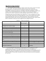
1
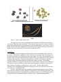
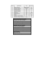
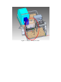
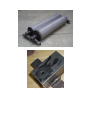
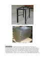
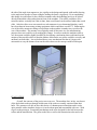
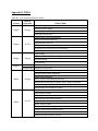
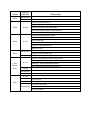
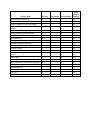
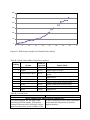
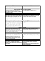
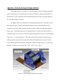
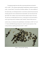
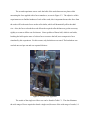
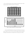
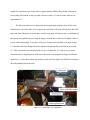
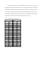
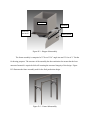
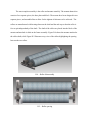
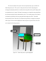
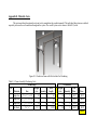
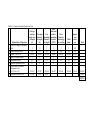
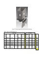
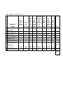
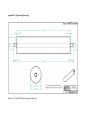
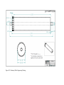
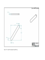
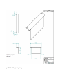
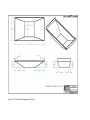
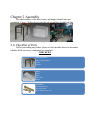
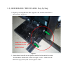
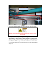
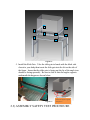
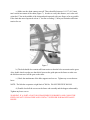
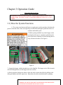
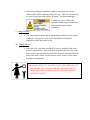
Ohio University Mechanical Engineering Senior Design Capstone Project “Staple Food Seed Crop Dehuller” The Plainsmen Jon Doucet Kevin Drummond Seth Gale Matt Mooney Mike Totterdale ABSTRACT The objective of the Senior Design Capstone Experience at Ohio University is to select an engineering project that will make a difference in the life of someone or a group of people in the community or region. The customer chosen by ―The Plainsmen‖ was the Appalachian Staple Foods Collaborative (ASFC). The mission of the ASFC is to grow and process staple food crops locally; these crops include buckwheat, spelt, amaranth, and beans. Available farming equipment is expensive and mostly used for large acre plots and can process a single crop. The ASFC, currently farming plots ranging in size from one quarter acre to two acres, have asked the group to design and manufacture a small-scale system to remove the outer shell from the seeds of buckwheat and spelt. The result is a pedal-powered machine that utilizes two textured rollers to break and peel the outer shell from the seed. The machine will ultimately be mounted on a trailer with threshing and cleaning equipment so that the overall system can be transported from site to site while being able process a range of crops. BACKGROUND The Ohio University senior design experience is set up to combine a group of five seniorlevel Mechanical Engineering students with a real-world customer. The objective is to select an engineering project that will make a difference in the life of someone or a group of people in the community or region. Throughout this project the group will perform analytical techniques of design, design construction and evaluation of the performance of an engineering system. The project focuses on the voice of the customer through dialogue, observations, surveys, etc. Once the problem of the customer was clear, the needs of the customer were transformed into specifications, and then conceptual design generation and selection began; background and benchmarking research were also utilized. The group chose the Appalachian Staple Foods Collaborative (ASFC) as the customers for the project. The ASFC was started two years ago by Michelle Ajamian and Brandon Jaeger; they are the primary customer contacts for the duration of the project. The ASFC mission is to ―build a regional bean, grain, and seed staple food system-which is focused on growing and processing high nutrition crops, while working toward zero dependency on chemical inputs in staple food agriculture and the development of appropriate scale farming and processing equipment [1].‖ The ASFC is in its second year of operation and is currently using land plots donated by local farmers to test if various crops grow well in the Appalachian area. The crops currently being farmed are millet, meal corn, amaranth, spelt, beans and buckwheat. The ASFC is farming plots ranging in size from a quarter acre to two acres and are planning on expanding to plots of approximately ten acres in the coming years. According to USDA research in 2007, 61.6% of all farms in Ohio ranged from 1 to 99 acres [2]. The designing and manufacturing of smaller scaled farming equipment has the possibility to be very beneficial, not only for the ASFC, but also throughout the Appalachian region of the country. STATEMENT OF THE PROBLEM The ASFC is in need of a machine to refine the staple seed crops being farmed after being cut in the field. The entire process includes (1) threshing, (2) cleaning, (3) deshelling/dehulling, and (4) cleaning. The goal of this project was to crack the shell of the seed and, if possible, separate the shell from the unbroken seed in the process. This process is known as ―dehulling‖ as the outer shell is also known as a ―hull‖. A variety of seeds from staple crops are grown by the ASFC, but the focus of the project is buckwheat and spelt. Buckwheat has been a major issue for the customer because the outer shell is hard to crack because it is thin (Figure 1), yet tough. Other impact dehullers have proven to be inefficient because once the machine was able to crack the hull the seed, which is soft and crumbles easily, the seed breaks up and is rendered useless. The spelt when separated from its stalk is coupled into pairs (Figure 2) which makes the dehulling process difficult. The hull is different from that of buckwheat because it has layers and is fibrous which resembles that of a grain which makes impact dehulling impossible. The hull must be almost peeled off of the seed. The fields being farmed range in size from quarter acre to two acre size plots. This leads to a desired customer throughput of a quarter acre of crop seed per hour or twenty-five bushels per hour. The machine must be small and light enough to be constructed/deconstructed easily enough so as to be taken from farm to farm across Athens County. The customers would like the design to be capable of being pedal-powered via a human. They are in contact with Job S. Ebenezer, Ph.D., president of Technology for the Poor, who has developed a device which can be attached to a standard bicycle allowing normal mechanical machines to be operated by human power [3]. Figure 1 – Buckwheat with and without its hull Figure 2 – Spelt on and off of its stalk The importance of focusing on small-plot farms is that in the United States, food travels "on average 1500 miles from seed to plate". This means the crops grown are raised for resilience, not for taste and nutrition [4]. Food bought from local, sustainable farms is often fresher, better tasting, and more nutritious compared to mass produced crops. Buying locally grown crops also supports the local economy and is better for the environment overall. RATIONALE The crops currently being grown include millet, meal corn, amaranth, spelt, beans and buckwheat. With regards to appropriate sizing—the plots of land range in size from quarter acre to two acres presently, but could increase to ten acres within a few years. Since the land plots are not side-by-side, the desired machine must be portable (able to be transported on roads), but also stationary while operating. Almost all of the machinery available on the market is stationary (and not portable) and includes both the dehulling and cleaning processes. The dehulling machines available are, in general, made to process a specific crop. Crop specific seed dehullers researched were for oats, sunflower seeds, buckwheat and peanuts. Research was also done on other methods of breaking or crushing objects, such as rocks. The three most feasible alternatives for the dehulling operation involved using two rollers, one roller on a concave wall or one roller on a vertically flat wall. In order to identify the applicable standards, the design and components of the machine were evaluated so that they met the standards and regulations of other farming applications. The main components found to be standardized were (1) the necessities of a road safe trailer (BMV), (2) general safety for agricultural equipment (OSHA) and (3) machine guarding (OSHA.) OSHA also provides standards for applications and methods of guarding or protecting the user from the rotating parts in machinery. Those that apply to farmstead equipment are listed in Appendix A.3. These standards will limit our design in that we will have to ensure that our machine has the proper guards on all moving pieces. Also, all safety instructions and training must be provided to each individual that plans to operate the machine. To consider this machine a success, specific goals were specified for the performance and usability of the machine. Table 1 displays the target design specifications for the project. Table 2 shows the needs of the customers. These specifications were chosen based on various levels of reasoning, including the most important reason of the capability of the machine to efficiently and effectively dehull the crop. To achieve this, a goal of greater than 90 percent efficiency was determined. With a machine operating at an efficiency of this level the customer would not be required to run the seeds through multiple times, saving time and energy. The speed at which the crop is capable of being processed is also another crucial metric of the system. Greater than 25 bushels per hour was chosen as the target process speed, this is roughly the equivalent of a quarter acre of crop. With the intended application of this product being small plots of land, the 25 bushels per hour target is significant enough to save time and energy by processing the crops at the plot location. Also included in the target of processing the crops on location, goals for the weight and size of the machine were set. The weight was intended to be less than 400 pounds, while the total footprint of the machine was not allowed to exceed a 5’x4’x4’ cube. This ensured that the machine is portable and capable of being placed on a trailer to be relocated to the plot site. The number of people required to operate the system determines how much time and effort will be spent on the processing of the crops. For this reason the target number of people required to operate the system was determined to be 1-2 people. Once the crop is loaded into the hopper and the slide gate is set to the desired flow rate, this machine can be operated by one person alone, but should be supervised for safety reasons. The maximum amount of power this machine was designed for was from one half to two horse power, while this is a large amount of power and could potentially be dangerous, the seeds require a large amount of force to crack the hull. The last metric to be set was the overall cost of the system. After researching existing equipment the total cost goal was set at less than $1000. This puts this machine in the range of affordable farm equipment, and allows for users from all backgrounds to benefit from the versatility and portability of this system. Table 1 – Target Design Specifications Table 2 – Customer Needs Ability to run as stand-alone machine Compatible with Team #2's design Able to be put on trailer or built on trailer Size and weight road-ready Stationary when operating Able to de-hull various seeds Maintained from spare equipment Cleaner screens interchangeable Easy to change huller settings between crops Variable speed Safe Limbs guarded from rotating machinery OSHA compatible Appropriately sized Pedal power with backup Figure 3 – Dehuller on Bed of Trailer DESIGN The final dehuller concept was chosen to be the roller-on-roller mechanism. Each of these methods was chosen after careful consideration for how well the concept would function; maintenance, ease of use, simplicity, and manufacturability were also taken into consideration. One of the rollers would be driven using a power source, however, it would be stationary and its mount would be bolted in that position on the frame. The other roller would not be driven; however, it would be able to move on the frame to variable distances from the other roller to allow for different sized seed crops to be passed through. The power source was determined to be a human pedaling a stationary bicycle (Figure 4) which has a chain that connects the bicycle’s gears to the shaft of a separate transmission that was geared to accept the belt that connects a gear already mounted on the driven roller. The rest of the design was then built around those key concepts. The two rollers used for the prototype were realized through a ―purchase solution‖ that were taken from a treadmill. The rollers are especially unique because they not only had a true central shaft, but bearings were also pressed into the inner diameter of the rollers. This made a great deal of difference because it not only cut cost but also significantly reduced manufacturing time. By utilizing the pressed bearings, it eliminated the need for bulky pillow bearings and allowed for cheaper custom steel mounts to be made in-house to connect the rollers onto the frame. It was decided that some kind of texture (Figure 7) would need to be put onto the rollers to ensure that the seeds would be pulled through. The rollers were sent to an outside source to be trued and to have a horizontal knurl texture be put onto them. Figure 4 – Overall Dehulling Machine Figure 5 – Rollers bolted to roller mounts and mounting rails Figure 6 – Steel Roller Mounts Figure 7 – Textured Rollers Figure 8 – Mounting Rails Sheet metal was used to encase the rollers for the purposes of the user’s safety and to contain the seeds within the machine. Angle iron was used as the frame for the machine and the steel roller mounts (Figure 6) were connected to it and provided the rollers with support (Figure 5). Sheet metal was also used to create a hopper (Figure 10) that would be able to hold the amount of twenty-five gallons of seed. A slide gate was created to control the flow of the seeds going into the rollers from the hopper. A steel metal slide was also created to be put underneath the rollers to catch the separated seeds and hulls and funnel them into transportable container. Figure 9 – Angle Iron Frame Figure 10 – Seed hopper DEVELOPMENT After initially assembling the prototype, various components of the design were determined that they could be revised in order to make a better product. The primary way to reduce time and cost is to weld the angle iron together as opposed to drilling holes and bolting it all together since thirty-four holes were drilled in all. It would save the cost of drill bits, bolts and nuts as well. A simple way to reduce the cost of the product would be to reduce the angle iron thickness from 1/4‖ and 3/16‖ to 3/16‖ and 1/8‖. This would also dramatically reduce the weight of the machine. Another aspect is to eliminate the two longer diagonal frame supports on the side of the angle iron supports to give rigidity to the design and instead weld smaller bracing to the angle iron in order to create triangles, making the frame a rigid body. By accomplishing this change it would allow for the collection container after the dehulling process to be placed directly beneath the rollers rather than in front of the machine. The rollers would have to be raised ten inches vertically but if this is done, then a seed funnel can be utilized rather than a seed slide. After the rollers were out-sourced to a sub-contractor it was determined that they could have been done in house using existing equipment which would have saved $375. Reducing the size of the roller mounts according to its position on the machine is another way to reduce the cost of the machine. The mounts were originally made all the same size for manufacturing purposes but costs could be cut by making this change. In order to make the machine easier to use, the mounts could be slightly modified by developing a mechanism that would attach to the mounts of the movable rollers so that the distance between the two rollers could be set easily and uniformly on both sides. It was idealized that a screw mechanism like that of a larger scale micrometer to vary the distance between the rollers however the concept could be built upon. Figure 11 – Optimized Design for Production EVALUATION Overall, the outcome of the project was a success. The machine does, in fact, crack most of the buckwheat seeds put through it and some of the seeds are actually extracted from their hulls. The customer was able to have their desire of a human-powered machine and it is also quite portable with a simplistic design so it can be taken apart and reassembled with ease. With respect to the prototype, a tensioning mechanism needs to be designed for the belt between the rollers and the transmission. The gears on the bike as well as the transmission also need to be adjusted and made true so that the chain is not as likely to come off. With that said, the design of the machine should work well. After the manufacturing phase, the dehuller was able to be powered and tested using both buckwheat and spelt; the result was a success for buckwheat, but the spelt seed was not properly removed from the hull. The buckwheat hulls were being cracked and some of the seeds were actually able escape from their hulls with a very small number of seeds breaking altogether. The spelt, a completely different type of seed, had moderate results. The hull of the seeds were being massaged just enough that with very little effort, the user is able to extract an unbroken seed from the many layers of the hull. With some vibration from the cleaner or transfer system, the seed should come out of the hull, but the dehulling process could be more efficient using more shear force rather than compressive force. A detailed evaluation of the prototype including specific results can be found in Appendix DISCUSSION The fully manufactured prototype will now be handed off along with user’s manual and CAD drawings to a Graduate Student who will make some of the changes mentioned in the Development section as well as add his own modifications that he feels will benefit the concept as well. He is also given the task of combining the dehuller with the thresher concept onto one trailer and being powered by a single power source. This is so that the customer may be able to take one trailer to a farm with the system able to thresh, dehull and clean various crops. Because some crops only require threshing, the threshing process will continue to be powered by a separate source than the dehuller. Appendix A. System Regulations A.1 Trailer Regulations Dimensions: Total length: 65 feet; trailer length: 40 feet; width: 102 inches; height: 13.6 feet. Hitch: When 1 vehicle is towing another vehicle, the drawbar or other connection may not exceed 15 feet from 1 vehicle to the other. When the connection consists only of a chain, rope, or cable, there shall be displayed upon such connection a white flag or cloth not less than 12 inches square. In addition to a drawbar or other connection, each trailer and each semitrailer which is not connected to a commercial tractor by means of a 5th wheel shall be coupled with stay chains or cables to the vehicle by which it is being drawn. Every trailer or semitrailer shall be equipped with a coupling device, which shall be so designed and constructed that the trailer will follow substantially in the path of the vehicle drawing it, without whipping or swerving from side to side. Lighting: Trailers must carry, either as part of the tail lamps or separately, 2 red reflectors. Trailers must be equipped with at least 1 red tail lamp visible from 500 feet to the rear and a white light to illuminate the license plate and render it visible from at least 50 feet from the rear. Trailers must be equipped with at least 2 stoplights, visible from 500 feet to the rear. Speed Limits: 55 mph is the maximum speed for any vehicle or vehicle combination that weighs over 8,000 lbs. A.2 Farm Equipment Regulations 1928.57(a)(6) Operating instructions. At the time of initial assignment and at least annually thereafter, the employer shall instruct every employee in the safe operation and servicing of all covered equipment with which he is or will be involved, including at least the following safe operating practices: 1928.57(a)(6)(i) Keep all guards in place when the machine is in operation; 1928.57(a)(6)(ii) Permit no riders on farm field equipment other than persons required for instruction or assistance in machine operation; 1928.57(a)(6)(iii) Stop engine, disconnect the power source, and wait for all machine movement to stop before servicing, adjusting, cleaning, or unclogging the equipment, except where the machine must be running to be properly serviced or maintained, in which case the employer shall instruct employees as to all steps and procedures which are necessary to safely service or maintain the equipment; 1928.57(a)(6)(iv) Make sure everyone is clear of machinery before starting the engine, engaging power, or operating the machine; 1928.57(a)(6)(v) Lock out electrical power before performing maintenance or service on farmstead equipment. A.3 Machine Guarding 1928.57(a)(7) Methods of guarding. Except as otherwise provided in this subpart, each employer shall protect employees from coming into contact with hazards created by moving machinery parts as follows: 1928.57(a)(7)(i) Through the installation and use of a guard or shield or guarding by location; 1928.57(a)(7)(ii) Whenever a guard or shield or guarding by location is infeasible, by using a guardrail or fence. 1928.57(a)(8) Strength and design of guards. 1928.57(a)(8)(i) Where guards are used to provide the protection required by this section, they shall be designed and located to protect against inadvertent contact with the hazard being guarded. 1928.57(a)(8)(ii) Unless otherwise specified, each guard and its supports shall be capable of withstanding the force that a 250 pound individual, leaning on or falling against the guard, would exert upon that guard. 1928.57(a)(8)(iii) Guards shall be free from burrs, sharp edges, and sharp corners, and shall be securely fastened to the equipment or building. 1928.57(a)(9) Guarding by location. A component is guarded by location during operation, maintenance, or servicing when, because of its location, no employee can inadvertently come in contact with the hazard during such operation, maintenance, or servicing. Where the employer can show that any exposure to hazards results from employee conduct which constitutes an isolated and unforeseeable event, the component shall also be considered guarded by location. 1928.57(c) Farmstead equipment 1928.57(c)(1) Power take-off guarding. 1928.57(c)(1)(i) All power take-off shafts, including rear, mid-, or side-mounted shafts, shall be guarded either by a master shield as provided in paragraph (b)(l)(ii) of this section or other protective guarding. 1928.57(c)(1)(ii) Power take-off driven equipment shall be guarded to protect against employee contact with positively driven rotating members of the power drive system. Where power take-off driven equipment is of a design requiring removal of the tractor master shield, the equipment shall also include protection from that portion of the tractor power take-off shaft which protrudes from the tractor. 1928.57(c)(1)(iii) Signs shall be placed at prominent locations on power take-off driven equipment specifying that power drive system safety shields must be kept in place. 1928.57(c)(2) Other power transmission components. 1928.57(c)(2)(i) The mesh or nip-points of all power driven gears, belts, chains, sheaves, pulleys, sprockets, and idlers shall be guarded. 1928.57(c)(2)(ii) All revolving shafts, including projections such as bolts, keys, or set screws, shall be guarded, with the exception of: 1928.57(c)(2)(ii)(A) Smooth shafts and shaft ends (without any projecting bolts, keys or set screws), revolving at less than 10 rpm, on feed handling equipment used on the top surface of materials in bulk storage facilities; and 1928.57(c)(2)(ii)(B) Smooth shaft ends protruding less than one-half the outside diameter of the shaft and its locking means. 1928.57(c)(3) Functional components. 1928.57(c)(3)(i) Functional components, such as choppers, rotary beaters, mixing augers, feed rolls, conveying augers, grain spreaders, stirring augers, sweep augers, and feed augers, which must be exposed for proper function, shall be guarded to the fullest extent which will not substantially interfere with the normal functioning of the component. 1928.57(c)(3)(ii) Sweep arm material gathering mechanisms used on the top surface of materials within silo structures shall be guarded. The lower or leading edge of the guard shall be located no more than 12 inches above the material surface and no less than 6 inches in front of the leading edge of the rotating member of the gathering mechanism. The guard shall be parallel to, and extend the fullest practical length of, the material gathering mechanism. 1928.57(c)(3)(iii) Exposed auger flighting on portable grain augers shall be guarded with either grating type guards or solid baffle style covers as follows: 1928.57(c)(3)(iii)(A) The largest dimensions or openings in grating type guards through which materials are required to flow shall be 4 3/4 inches. The area of each opening shall be no larger than 10 square inches. The opening shall be located no closer to the rotating flighting than 2 1/2 inches. 1928.57(c)(3)(iii)(B) Slotted openings in solid baffle style covers shall be no wider than 1 1/2 inches, or closer than 3 1/2 inches to the exposed flighting. 1928.57(c)(4) Access to moving parts. 1928.57(c)(4)(i) Guards, shields, and access doors shall be in place when the equipment is in operation. Appendix B. FMEA Table B.1. List of Potential Failure Modes System Mode of Operation Hopper Design Hopper In Use Hopper Storage Hopper Maintenance Transporting Huller Design Huller In Use Failure Mode Walls bending Agitator fails to agitate Improper gear ratio to agitator (insufficient torque/ rotate too fast) Slide gate not effective Stands come loose from fasteners Hopper structure insufficient Agitator parts crack off Slide gate sticks (open/closed) Ergonomically inefficient to lift seeds high Sharp edges Paint flaking Holes in sheet metal from rusting Agitator rusting Legs rusting Hoppers too top heavy Bearings designed insufficiently Bearing insufficiently supported Shaft sized incorrectly Roller surface manufactured unevenly Manufacturing tolerances (cutouts, plum, square, backlash) Rollers not square with each other (uneven adjustment) Adjustment screw theads too coarse Shaft breaks Gear comes off shaft Shaft-roller connection breaks Safety-Pinch point between rollers Adjustable mechanism locks up Roller surface cracks Texture on rollers wearing down Debris/ stones stuck between rollers Wear on the adjustment mechanism Rollers become eccentric/ uneven System Huller Mode of Operation Maintenance Transporting Motor Design Motor In Use Motor Maintenance Failure Mode Rollers contact each other Motor power insufficient Supports fail Motor vibrations break other things Inability to reduce speed to desired RPMs Decreased efficiency through use Safety- Motor shaft pinch points Insufficient lubrication Drive shaft fails Incorrect air-fuel ratio Injectors clog from bad fuel Run out of fuel Pistons seizing Safety- Noise level too loud Transporting In Use Gears/ Pulleys/ Belts Misc. Storage Maintenance Transporting In Use Storage Maintenance Transporting Safety- All gears/pulleys have pinch points Belts snap Shear pin / shaft connection point fail Belt comes loose from pulley (slippage) Tires dry-rot Brake lights fail Too heavy for trailer Flat tire Unsafe for road Table B.2. Risk Rankings for Potential Failure Modes Failure Mode Walls bending Agitator fails to agitate Improper gear ratio to agitator (insufficient torque/ rotate too fast) Slide gate not effective Stands come loose from fasteners Hopper structure insufficient Agitator parts crack off Slide gate sticks (open/closed) Ergonomically inefficient to lift seeds high Sharp edges Paint flaking Holes in sheet metal from rusting Agitator rusting Legs rusting Hoppers too top heavy Bearings designed insufficiently Bearing insufficiently supported Shaft sized incorrectly Roller surface manufactured unevenly Manufacturing tolerances (cutouts, plum, square, backlash) Rollers not square with each other (uneven adjustment) Adjustment screw threads too coarse Shaft breaks Gear comes off shaft Shaft-roller connection breaks Safety-Pinch point between rollers Adjustable mechanism locks up Roller surface cracks Texture on rollers wearing down Debris/ stones stuck between rollers Wear on the adjustment mechanism Rollers become eccentric/ uneven Rollers contact each other Severity 1 4 Likelihood 2 2 Risk Priority Dectectability Number 10 20 3 24 5 2 6 6 8 3 1 2 3 3 5 4 1 3 2 2 8 4 5 12 36 36 320 48 6 6 1 3 2 6 7 8 8 8 3 5 1 9 6 6 6 4 1 2 1 2 6 1 2 3 4 3 4 7 6 2 2 180 6 18 54 48 108 112 56 96 16 12 3 5 5 75 4 3 5 5 5 6 3 3 2 4 2 3 3 4 2 5 3 3 9 4 5 8 7 6 6 2 2 8 9 6 9 4 5 9 3 8 3 2 4 32 48 225 90 135 216 60 135 48 224 36 36 24 Failure Mode Motor power insufficient Supports fail Motor vibrations break other things Inability to reduce speed to desired RPMs Decreased efficiency through use Safety- Motor shaft pinch points Insufficient lubrication Drive shaft fails Incorrect air-fuel ratio Injectors clog from bad fuel Run out of fuel Pistons seizing Safety- Noise level too loud Safety- All gears/pulleys have pinch points Belts snap Shear pin / shaft connection point fail Belt comes loose from pulley (slippage) Tires dry-rot Brake lights fail Too heavy for trailer Flat tire Unsafe for road Severity 5 7 6 Likelihood 2 5 5 Risk Priority Dectectability Number 1 10 6 210 7 210 5 3 7 2 6 5 5 5 5 6 2 5 8 8 3 2 2 4 2 6 1 6 6 8 8 8 8 1 9 5 10 90 336 128 144 80 80 20 90 180 7 6 5 4 6 6 8 5 9 6 6 5 7 5 6 2 5 3 6 4 6 8 3 9 3 5 3 252 144 150 224 90 324 48 125 81 300 250 200 150 100 50 0 0 5 10 15 20 25 30 35 40 45 Figure B.1. Risk Priority Numbers for Potential Failure Modes Table B.3. Main Failure Modes Using Pareto Analysis Ranking System 1 Motor 2 Hopper 3 Gears/ Pulleys/ Belts 4 5 6 7 8 9 Huller Gears/ Pulleys/ Belts Huller Huller Motor Motor Mode of Operation Failure Mode In Use Safety- Motor shaft pinch points In Use Agitator parts crack off Safety- All gears/pulleys have pinch In Use points In Use Shaft breaks In Use Belt comes loose from pulley (slippage) In Use Debris/ stones stuck between rollers In Use Safety-Pinch point between rollers Design Motor vibrations break other things Design Supports fail Table B.4. Action Items Problem Action Item Motor Supports Fail/ Huller Housing Supports Fail If the motor supports fail, the motor could A static load analysis will be done to determine potentially fall while running. With pulleys proper materials and geometries for both coming off the motor, this could cause serious support structures. harm to anyone near it at time of failure. If the Problem Action Item huller housing fails, the roller tolerances could be unobtainable and unsafe for use. Motor Vibrations Damage Other Equipment Vibrations from the motor cause parts to Look into dampers for motor to sit on. loosen, parts to be out of tolerance, or damage equipment over time. Debris/ stones stuck between rollers If rocks or other unwanted debris falls into Put a screen on the top of the huller hopper to rollers, the flow rate will be decreased and will prevent large pieces of debris to fall in. Create require the machine to shut down. Also could a squeegee-like cleaner for the huller. cause potential failure of rollers and stress on bearings. Belt comes loose from pulley (slippage) While in use, belts and pulleys can slip causing Properly design belts. Have tensioners on all decreased efficiency and power to the desired pulleys. mechanism. This could cause variability in the speed of the winnowing fan or speed of the rollers; variability in these speeds would be detrimental to the machine. Roller Shaft breaks If either of the roller shafts break, the entire Properly design shaft (accurately measure huller would be out of service. Also, if the forces on shaft, manufacture correctly, etc.) shaft broke, there would be a safety issue with the heavy rollers rotating unevenly. Agitator parts crack off If the welds fail on the hopper agitator, parts Design the agitator to try and decrease the could potentially come off. If they then fit possibility of welds failing and pieces falling through the opening in the slide gate, they off. could fall into the rollers and cause serious damage and a safety hazard. Safety-Pinch Point Between Rollers/ All gears and pulleys/ Motor shaft Pinch points with all rotating equipment is a Whenever possible, guards will be installed to serious hazard. Clothing getting pulled prevent accidental contact with rotating through or fingers getting stuck could result in equipment. serious injury. Signs/ stickers will be put near rotating parts warning of the danger. Appendix C. Mock-Up Testing for Design Validation Three experiments were conducted to verify the designs chosen, all relating to the huller portion of the system. The experiments were done to determine: (1) optimal spacing between huller rollers; (2) force required to break buckwheat and spelt seeds; and (3) required angle for the seed slide coming off of rollers. The purpose of the first experiment was to determine the gap size for each type of seed— buckwheat and spelt—where the hull is broken while the inner seed remains intact; this is important because some of the customer’s products require a whole seed rather than allowing broken seeds. The design chosen uses two rotating rollers to crack the seeds between them. A small-scale replica of our system was built to test different gaps between the rollers (scaled down from 5‖ to 1½‖), shown in Figure C.1. The texture of the rollers also plays a large role in the ability to pull the crops into the spacing of the rollers. Horizontal knurls were spaced so that crops could not get stuck between the spacing and would have enough ―grip‖ to force the seeds through. The rollers were spaced at 0.08‖, 0.085‖, 0.087‖, 0.09‖, and 0.1‖. Figure C.1- Roller Spacing Experiment Apparatus The optimum spacing between the rollers for processing buckwheat was found to be 0.0935 ± 0.0065‖. This experiment required qualitative and quantitative methods to interpret the results. As seen in Figure C.2, the seeds were in different conditions. The various conditions of the seeds after they were fed through the rollers were: the hull not cracked, hull cracked and seed remaining in the hull, seed not crushed and removed from the hull, seed removed from the hull and crushed. These conditions were the criteria used for the qualitative analyses of the results. The seeds were successfully hulled if the seed was: (1) whole and (2) was removed from hull or on the verge of being removed. At distances of 0.08‖ and 0.085‖ almost all of the seeds were cracked, so they were obviously not the optimal distances. At the distances of 0.087‖, 0.09‖, and 0.1‖ the successful hull breaking percentage was 81, 86, and 71 percent, respectively. These results provided an acceptable gap clearance of 0.0935‖ ± 0.0065‖. Figure C.2- Results of 0.09‖ Spacing The second experiment was to crack the hulls of the seeds between two plates while measuring the force applied with a force transducer, as seen in Figure C.3. The objective of this experiment was to find the hardness of each of the seeds; this is important because the force from the seeds will be the main forces on the roller shafts, which will dramatically affect the shaft size. Also, the force to break the seeds affects the required roller thickness to get the necessary rigidity so as not to deflect out of tolerance. Since spelt has a fibrous hull, which is not brittle, breaking the hull requires more of a shear force to remove the hull, not a compressive force simulated by this experiment. For this reason, only buckwheat was tested. The buckwheat was cracked one seed per test and was repeated 60 times. Figure C.3- Force Test Apparatus The results of the single seed force test can be found in Table C.1. The data illustrates the wide range of forces required to break a single seed; because of the wide range of results, 1.8 – 62.5 N, a more definitive graph was made to help illustrate the important force results. Figure C.4 shows the number of seeds that were broken in a 5-Newton range. Table C.1- Force to Break Hulls 13.92 18.75 24.32 28.24 27.29 17.38 22.64 27.08 30.26 12.48 Force to Break Hull (Newtons) 2.47 15.6 5.66 28.58 13.77 23.65 27.88 15.2 20.99 49.64 32.77 5.99 2.72 7.4 7.34 18.88 29.25 3.18 16.58 39.29 23.8 30.35 42.69 33.32 12.66 16.61 20.93 3.12 26.59 22.61 62.49 23.96 23.84 9.33 2.47 12.33 16.83 26.62 19.28 11.78 9.33 3.12 25.3 1.8 27.26 11.07 25.4 34.73 19.67 22.83 Average = 20.2 N 12 Number of seeds 10 8 6 4 2 0 1-5 5-10 10-15 15-20 20-25 25-30 30-35 35-40 40-45 45-50 50-55 Newtons Figure C.4- Number of Seeds Broken in 5-Newton Force Range It can be seen that the bulk of the forces are between 15 and 30 Newtons. For this reason, it can be assumed the average of 20.2 Newtons is reliable. Using this information, along with the calculating the maximum number of seeds along the rollers is 200 (using seed size and roller length), the maximum force on the rollers is approximately 4000N (900 pounds). Using these forces along with tension on the gear (and a factor of safety of 2), the necessary shaft size is approximately 1‖. The third experiment was to determine the minimal angle needed to have all the seeds and hulls move down the slide. At low angles, the coefficient of friction will not allow the hulls and seeds from sliding down, but an unnecessarily steep angle will increase the overall height of the system causing difficulty accessing the hopper (located above rollers) and a higher center of gravity while transporting. To test this, a flat piece of sheet metal was held at an angle (Figure C.5) and the seeds were dropped from the minimum height that they would fall in the system (3‖). This experiment was conducted with two sets of conditions: (1) seeds at rest, no motor vibrations and (2) dropping seeds, with motor vibrations (varying applied voltage for different intensities). A visual observation was then used to decide if the angle was sufficient to transport the seeds and hulls down the slide. Figure C.5- Seed Slide Test Apparatus The results from each case can be found in Table C.2 and C.3, respectively. For static loading, the average angle that made all seeds move was approximately 20 degrees for both spelt and buckwheat. With motor vibrations the angle decreases to 15 degrees for most cases, but not for low applied voltages; at 20 degrees, all seeds fell for all applied voltages. This shows if the motor did not provide considerable vibrations, the seeds would not adequately slide at angles less than 20 degrees; for this reason, the slide angle was chosen to be 20 degrees. Table C.2- Slide Angle Experiment Results Spelt Angle Trial (degrees) 1 25 2 20 3 18 4 19 5 19 6 20 7 19 8 19 9 19 10 17 11 19 12 19 13 22 14 18 15 20 16 18 17 18 18 17 19 19 20 19 Average: 19.2 Buckwheat Angle Trial (degrees) 1 20 2 20 3 19 4 21 5 21 6 20 7 20 8 20 9 20 10 21 11 19 12 19 13 18 14 19 15 18 16 19 17 18 18 19 19 20 20 20 Average: 19.6 Table C.3- Average Amplitude of Accelerometer as a Function of Voltage Average Amplitude (mm) Slide? Buckwheat Angle Voltage (V) x y z Spelt 5o 5 10 11 14 0.605 1.82 2.05 0.55 1.72 2.78 3.56 1.64 3.4 3.43 4.32 1.29 NO NO NO NO NO NO NO NO 10 10 11 14 1.17 1.35 5.3 3.26 4.65 4.41 3.43 5.21 10.46 NO NO YES NO NO YES 15o 5 10 11 14 1.66 2.24 2.23 4.28 1.46 2.36 2.95 6.67 2.3 5.14 5.16 9.79 NO YES YES YES YES YES YES YES o Appendix D. Final Design for Production During the construction and testing of the prototype, certain design features were realized to be undesirable. For this reason the following changes are proposed if a production model was to be created: Add More Guards Add 10‖ to Leg Height Replaced Slide with Funnel Replaced Bolts with Welds Add Bracing on Corners Remove Diagonal Bracing Decrease Angle Iron Thickness Manufacture Rollers from Pipe, Bearings, and Shaft The reasons for making these changes include increasing safety, usability, function, or decreasing materials or production costs. A CAD model of the revised system for production is shown in Figure D.1, below. This model features minimal material, and maximum safety. The main system components include a hopper assembly, frame assembly, roller and mounts assembly, and lastly a funnel and guard assembly. Figure D.1- Production Model The hopper assembly includes the hopper, a slide gate, and the mounting hardware to attach the hopper to the frame assembly. The hopper serves the purpose of containing the raw crop and feeding it into the moving roller assembly. The slide gate is used to regulate the flow rate of the raw crop from the hopper into the rollers. The mounting hardware includes two sets of bolts, nuts, and washers to attach the hopper to the frame assembly via two welded pieces of angle iron as shown in Figure D.2 below. Hopper Slide Gate Mounting Hardware Safety Shield Figure D.2 – Hopper Subassembly The frame assembly is comprised of 17 feet of 3/16‖ angle iron and 3.5 feet of ¼‖ flat bar for bracing purposes. The structure of the assembly has been minimized to ensure that the least amount of material is required while still ensuring the structural integrity of the design. Figure D.3 illustrates the frame assembly used for the final production design. Figure D.3 – Frame Subassembly The most complex assembly is the roller and mounts assembly. The mounts themselves consist of two separate pieces, the base plate and block. The mounts have been designed in two separate pieces, and assembled last to allow for the tightest of tolerances to be achieved. The rollers are manufactured with bearings between the shaft and the end caps so that the roller is free to spin independently of the shaft. The shaft of the rollers are placed into the block of the mounts and attached via bolts to the frame assembly. Figure D.4 shows the mounts attached to the roller shafts, while Figure D.5 illustrates a top view of the rollers highlighting the spacing between the two rollers. D.4 – Roller Subassembly D.5 – Roller spacing The last sub assembly of the system is the most important safety aspect, and that’s the funnel and guard system. This system is what protects the user from the many dangerous moving parts and pinch points that are created by the moving rollers; these specific danger points are included in the user’s manual. The funnel’s main purpose is to funnel the seeds and chaff into the collection unit placed directly underneath the system. The secondary purpose of the funnel is to eliminate the possibility of the user getting their hand caught in the rollers. The shields, located on all four sides of the rollers, also eliminate this possibility by completely encasing the rollers. Figure D.6 shown below highlights the funnel and protective guards. Please refer to the user’s manual for all safety precautions. Safety Shield Safety Shield Funnel Figure D.6 – Funnel and protective guards highlighted Combining the subassemblies results in a buckwheat and spelt huller that is safe and dependable. The system works by depositing the raw seeds into the hopper and regulating the flow rate into the spinning rollers by using the slide gate. The seeds then fall into the spinning rollers where they are forced through the space between the two rollers, resulting in the shell cracking, and in some cases the shell and seed being separated. Once the seeds fall through the rollers they are funneled into a collection unit via the funnel. With the outer shells cracked the seed within is free to fall out and separate itself from the shell during the collection process. The complete operating instructions, as well as safety, maintenance and service information can be found in the user’s manual included in the appendix. Appendix E. Materials Costs This section outlines the materials costs and cost to manufacture the production model. The individual subsystems are outlined separately to shown the cost breakdown throughout the system. The overall system cost is shown in Table E.9, below. Figure E.1- Production Frame with Parts Labeled for Purchasing Table E.1- Frame Assembly Purchasing Costs From Design Part Length # Material Size (in.) To Purchase Quantity Total Length Length (in.) Quantity Unit Price Price 1 Angle Iron 1 1/2 x 1 1/2 x 1/8 30 2 60 60 1 $8.12 $8.12 2 Angle Iron 1 1/2 x 1 1/2 x 3/16 12 2 24 24 1 $4.29 $4.29 30 4 120 60 2 $9.66 $19.32 5 2/3 8 45.28 48 1 $4.92 $4.92 $36.65 3 5 Angle Iron Flat Stock 1 1 1 /2 x 1 /2 x 3/16 1 1" x /4" Table E.2- Frame Assembly Production Costs a. b. c. d. e. f. g. h. Explanation of Operation Time to Complete Operation (hr) Labor Rate (per hour) Labor Cost (=a*b) Basic Overhead Factor Equipment Factor Special Operation Factor Total Labor/ Overhead/ Equipment Cost (=c*(1+d+e+f)) Purcased Material Cost Drill holes and Cut slots in Place mounting mounting frame in brackets bracket various jigs to length (CNC) for welding Cut legs and top angle iron to length (6) Cut angle brackets to length (8) 2 $12 $24.00 1 0.5 0 1.5 $12 $18.00 1 0.5 0 1 $12 $12.00 1 0.5 0 2 $15 $30.00 1 0.5 0 $36.00 $27.44 $27.00 $4.92 $18.00 $4.29 $45.00 Weld frame Inspect and clean up 2 $12 $24.00 1 0.5 0 2 $12 $24.00 1 0.5 0 0.25 $12 $3.00 1 0.5 0 $36.00 $36.00 $4.50 Total $202.50 $36.65 $239.15 Figure E.2- Production Hopper System with Parts Labeled for Purchasing Table E.3- Hopper Assembly Purchasing Costs From Design Part # Material 1 Angle Iron Size 1 1 /2 x 1 1/2 x 1 /8 2 3 4 Angle Iron Sheet Metal Sheet Metal 1/2 x 1/2 x 1/8 20 gauge 20 gauge 5 Sheet Metal 20 gauge Length (in.) To Purchase Quantity Total Length /Area Length (in.)/ Area (in2) Quantity Unit Price Price 15.375 2 30.75 36 1 $4.64 $4.64 18.75 27"x20" 19.5"x12" 10" x 30.2" 1 2 2 18.75 54" x 40" 39" x 24" 24 24" x 36" 12" x 24" 1 2 2 $5.82 $20.02 $6.67 $5.82 $40.04 $13.34 2 20" x 60.4" 12" x 36" 2 $10.67 $21.34 $85.18 Table E.4- Hopper Assembly Production Costs a. b. c. d. e. f. g. h. Explanation of Operation Time to Complete Operation (hr) Labor Rate (per hour) Labor Cost (=a*b) Basic Overhead Factor Equipment Factor Special Operation Factor Total Labor/ Overhead/ Equipment Cost (=c*(1+d+e+f)) Purcased Material Cost Cut angle iron to support hopper Drill holes in angle iron support and hopper Cut slide gate handle to length Layout cuts on sheetmeta l Cut and bend sheetmetal Place into jig and weld Cut holes Inspec and rivet t and handle to clean slide gate up 1.5 $12 $18.00 1 0.5 0 3 $12 $36.00 1 0.5 0 1.5 $12 $18.00 1 0.5 0 1.5 $12 $18.00 1 0.5 0 2 $12 $24.00 1 0.5 0 0.5 $12 $6.00 1 0.5 0 1 $12 $12.00 1 0.5 0 0.25 $12 $3.00 1 0.5 0 $27.00 $74.72 $54.00 $27.00 $27.00 $4.64 $36.00 $9.00 $5.82 $18.00 $4.50 Total $202.5 0 $85.18 $287.6 8 Figure E.3- Production Roller System with Parts Labeled for Purchasing Table E.5- Roller Assembly Purchasing Costs From Design Part # 1 2 3 4 5 Material Steel Flat Bar Square Stock Bearings Round Bar Schedule 40 Size 1/2" x 1" 1 1/2" x 1 1/2" 4.5" OD 1 1/5" OD 5" OD Length (in.) To Purchase Total Length Quantity /Area Length (in.)/ Area (in2) Quantity Unit Price Price 4 3/4 4 19 24 1 $3.24 $3.24 2 3/4 4 4 2 2 11 12 56 49 60 60 1 4 1 1 $11.93 $8.23 $12.60 $58.63 $11.93 $32.92 $12.60 $58.63 $119.32 27.875 24.625 Table E.6- Roller Assembly Production Costs a. b. c. d. e. f. g. h. Explanation of Operation Time to Complete Operation Labor Rate Labor Cost (=a*b) Basic Overhead Factor Equipment Factor Special Operation Factor Total Labor/ Overhead/ Equipment Cost (=c*(1+d+e+f)) Purcased Material Cost Cut roller pipes to length 2 $12 $24 1 0.5 0 Cut roller shafts to length 1.5 $12 $18 1 0.5 0 Press fit bearings into pipe 2 $12 $24 1 0.5 0 Cut mounting block stock to length 3 $12 $36 1 0.5 0 $36.00 $58.63 $27.00 $12.60 $36.00 $32.92 $54.00 $15.17 Drill 1" holes in stock for shaft 3 $12 $36 1 0.5 0 Drill 3/8" holes in bottom mount 1.5 $12 $18 1 0.5 0 Weld mounting block together 2 $12 $24 1 0.5 0 Inspect and clean up 0.25 $12 $3 1 0.5 0 $54.00 $27.00 $36.00 $4.50 Total $274.50 $119.32 $393.82 Figure E.4- Production Funnel with Parts Labeled for Purchasing Table E.7- Seed Funnel Purchasing Costs From Design Part # Material 1 Sheet Metal Size 415 in2 Length (in.) NA To Purchase Total Length Quantity /Area 1 415 Length (in.)/ Area (in2) 1152 Quantity 1 Unit Price $26.68 Price $26.68 $26.68 Table E.8- Seed Funnel Production Costs a. b. c. d. e. f. g. h. Explanation of Operation Time to Complete Operation Labor Rate Labor Cost (=a*b) Basic Overhead Factor Equipment Factor Special Operation Factor Total Labor/ Overhead/ Equipment Cost (=c*(1+d+e+f)) Purcased Material Cost Layout Cut and cuts on bend sheetmetal sheetmetal Place sheetmetal in jig and weld Inspect and clean up 2 $12 $24 1 0.5 0 3 $12 $36 1 0.5 0 1 $12 $12 1 0.5 0 0.25 $12 $3 1 0.5 0 $36.00 $26.68 $54.00 $18.00 $4.50 Table E.9- System Assembly Overall Costs Subsystem Materials Frame $36.65 Hopper/ Slide Gate $85.18 Rollers/ Mounting Structure $119.32 Funnel $26.68 Total $267.83 Manufacturing $202.50 $202.50 $274.50 $112.50 $792.00 Total $239.15 $287.68 $393.82 $139.18 $1059.83 Total $112.50 $26.68 $139.18 Appendix G. Engineering Drawings Figure G.1- Adjustable Roller Engineering Drawing Figure G.2- Stationary Roller Engineering Drawing Figure G.3- Angle Bracing Engineering Drawing Figure G.4- Guard #1 Engineering Drawing Figure G.5- Guard #2 Engineering Drawing Figure G.6- Guard #3 Engineering Drawing Figure G.7- Seed Hopper Engineering Drawing Figure G.8- Hopper Mounting Bracket Engineering Drawing Figure G.9- Long Frame Angle Iron Engineering Drawing Figure G.10- Mounting Block Engineering Drawing Figure G.11- Angle Iron Mounting Rail #1 Engineering Drawing Figure G.12- Angle Iron Mounting Rail #2 Engineering Drawing Figure G.13- Seed Funnel Engineering Drawing Appendix H. Design Evaluation The original customer specifications with the results of the prototype analysis are shown in Table H.1, below. The main specifications which were not met were (1) having interchangeable screens for the screener, (2) having the rotating parts guarded, (3) OSHA compatibility, and (4) having pedal power with backup. Due to time and funding constraints, the screener was not manufactured; this led to the complete screener missing the customer specification. For safety consideration, machine guarding is preferred for any machine with rotating parts. But because the design only uses pedal power, it is not as important as if a motor was used. OSHA specifications are listed in Appendix A; more research would need to be done to fully understand if the system meets OSHA requirements. Lastly, pedal power is the sole method of powering the system; the main reason for this is the final layout of the systems on the trailer is not known, so the power source might need to be changed or moved. Table H.1- Customer Specifications Customer Specifications Did the Design Meet the Specs.? Ability to run as stand-alone machine Compatible with Team #2's design Able to be put on trailer or built on trailer Size and weight road-ready Stationary when operating Able to de-hull various seeds Maintained from spare equipment Cleaner screens interchangeable Easy to change huller settings between crops Variable speed X Safe Limbs guarded from rotating machinery OSHA compatible - Appropriately sized Pedal power with backup X Comments The cleaner was not manufactured Not all moving parts have guards Not all moving parts have guards No backup As seen by Table H.2, the prototype meets the majority of the specifications set at the beginning stage of the project. The weight and the dimensions are well within the set specifications. More testing is required to fully assess the performance of the prototype. Once the testing of the prototype is complete, the speed of the process, the noise level, and the efficiency can be determined. At this stage of the project, the only specification not met by the prototype is the sales price. A unique feature of the prototype is the texture of the rollers. There are horizontal knurls along the length of the rollers. This allows the seeds to be gripped and pulled down between the rollers. This aspect of the design worked very well. The project should continue, but the prototype is not ready for production. This is the first prototype of this project. The minimal testing of the target crops, buckwheat and spelt, that has been completed has shown the huller is capable of removing the hull from samples of buckwheat. Regarding spelt, more of a shearing motion would benefit the removal of the layered hull. This could possibly be achieved by designing the rotation of the two rollers at different speeds. This will require more testing of the two different roller speeds working in parallel with varied roller spacing to determine the maximum efficiency that can be achieved. There is the possibility to incorporate the team’s previous concept designs with the prototype frame. To do this, the adjustable roller could be removed and replace with a concave wall or a flat. Figure H.1 shows an example of the concave wall. Flanges can be added to the ends of this wall to align with the adjustable slots. Small ribs could be applied to the inner surface to create edges for gripping the hulls as they are force between the roller and the wall. Table H.2- Design Specifications Units Ideal Value Actual Value Specification Speed of Process Bushels/Hour > 25 Weight of Machine Width of Machine Length of Machine Height of Machine Sales Price Maximum Power Pounds Feet Feet Feet US$ HP < 400 <4 <5 <4 < 1,000 0.5 – 2 Noise db < 90 Efficiency % > 90 Number of People to Operate Person 1-2 Pending Testing ≈ 200 1.25 2.5 2.92 > 1,000 <0.5 Pending Testing Pending Testing 2 Specification Met? Unknown Yes Yes Yes Yes No Yes Unknown Unknown Yes Figure H.1- Example concave wall Appendix I. User’s Manual Created By The Plainsmen Table of Contents Chapter 1 Safety Chapter 2 Assembly Chapter 3 Operation Guide Chapter 4 Disassembly and Storage Chapter 5 Maintenance and Replacement Parts Chapter 1 Safe Operation Procedures Warning! This symbol represents a hazardous situation or area of the machine, that if not avoided could result in death or serious injury. This unit contains many moving parts and sharp edges. All users must ALWAYS wear personal protective equipment, including Eye protection Hand protection In order to decrease the risk of death or serious injury, please follow all precautions and warnings while working with or around this piece of equipment. SAFETY HAZARD SYMBOLS USED IN THIS MANUEL: Rollers contain pinch points between the rollers and the belts attached to the gears. Keep all hands away from parts when moving. Object contains sharp edges. Keep hands and fingers away. Machinery contains moving parts. Keep all extremities away. Use Eye protection when utilizing machinery. Warning! Object may be heavy and could cause injury to back or muscles. Use caution when lifting. Chapter 2 Assembly The subassemblies of the bike, frame, and hopper should come preassembled. Figure 1 below shows what the sub assemblies should look like. Figure 1 2.1) Checklist of Parts Before proceeding any further, please use the checklist below to determine whether all the necessary components are supplied. CHECKLIST SubAssemblies •Bike and Bike Supports •Frame •Hopper Parts •Chain •Belts •Slide Gate •Motor Hardware •Two Wood Screws •Four 9/16" Bolts •Four Washers, Four Nuts 2.2) ASSEMBLING THE HULLER- Step by Step 1. Begin by screwing the front bike support to the wooden motor base as shown below. (Figure 2) Insert the screws as shown by the green arrows Figure 2 2. Attach chain from bike to the sprocket attached to the end of the motor. The attachment should look similar to Figure 3 below. Make sure the chain lines up perfectly and is not angled or offset. Attached to the largest diameter sprocket Attach to the 3rd largest sprocket Figure 3 3. Now, attach the belt from the roller gear to the other side of the motor. WARNING: Beware of pinch points between the gears and rollers. Make sure all parts are not moving. 4. Line up the subassembly of the hopper to the top of the frame. Follow the procedure on figure 4 below to line up the holes in the angle iron on the hopper to the angle iron of the frame. The frame will be labeled with letters A-D as will the hopper. Line up the similar letters onto the frame. Use the bolts, washers and screws provided to secure the hopper in place. (Figure 4) D C A D B C A B Figure 4 5. Install the Slide Gate. Take the slide gate in hands with the black side closest to your body then insert the slide gate into the slit on the side of the frame. Insure that the slide gate is facing up (the lip of the angle iron should be facing upwards). Be sure to slide it onto the angles supports underneath the hopper as shown below. Figure 6 Angle iron piece on bottom of hopper to guide slide gate in. 2.3) ASSEMBLY SAFETY TEST PROCEDURE a.) Make sure the chain cannot come off. There should be between 1/4-1/2‖ (6-12 mm) total vertical movement of the chain (Figure 7). In order to verify this distance, use a ruler and orient the 0‖ line in the middle of the chain and push upwards with your finger as far as possible. If the chain has moved upwards at least ¼‖ but not exceeding ½‖ then your chain has sufficient tension for use. Figure 7 b.) The belt should also contain sufficient tension so that the belt can remain on the gears. Also, double check to make sure that belt is between the guide pins on the frame to make sure the belt does not travel off the gear on the roller. c.) Check the attachments of the bike supports and screws. Tighten any screws that are loose. NOTE: The bike has a operator weight limit of 300 lbs. DO NOT EXCEED 300 LBS. d.) Double check all the screws on the frame sub assembly and the hopper subassembly. Tighten any loose screws. WARNING: IF A PART A PART OR SUBASSEMBLY IS BROKEN AND CANNOT BE FIXED, DO NOT USE MACHINE AND CONTACT SUPPLIER FOR MAINTENANCE ISSUES. Chapter 3 Operation Guide Operating Instructions Perform above safety instructions and inspection WARNING: THIS HULLER IS MEANT TO BE USED WITH AT LEAST TWO OPERATORS. BE SURE TO HAVE ANOTHER PERSON WITH YOU AT ALL TIMES. 3.1) How the System Functions 1.) The system uses human pedal power to apply power to the sprockets which turn the gears to rotate the rollers. Have one operator get on the bike and begin to pedal the rollers at a constant comfortable speed. 2.) Before putting unhulled crop in the hopper, make sure that the slide gate is completely pushed into the side of the frame, rendering it closed ensuring that no crop will enter the rollers. See Figure 8. Slide Gate is Fully opened. Slide Gate is Fully closed. Figure 8 3.) Supply the hopper with the intended crop to be dehulled. The hopper can be filled as much as desired though make sure the hopper does not overflow. 4.) Slowly open the slide gate in order to allow the seeds to enter the rollers by pulling on the slide gate handles (the black angle iron). Remember, the rollers should already be spinning WARNING: BE SURE TO WEAR SAFETY GLASSES WHEN SUPPLYING ROLLERS WITH SEEDS TO DECREASES RISK OF INJURY TO EYES. BEFORE opening the slide gate. MAKE SURE THAT THE OPERATOR DOES NOT PUT HANDS INSIDE HOPPER OR NEAR MOVING PARTS. 5.) When finished dehulling seeds, close the slide gate. Continue to spin rollers until all seeds have gone through. DO NOT ABRUPTLY STOP PEDALING THE ROLLERS. Instead, slowly decrease pedaling speed until the rollers come to a slow steady stop. Immediately stopping the pedaling will result in the chain coming off the motor or bike and busting the chain itself. WARNING: IF AT ANY POINT THE DEHULLER BREAKS DURING USE, IMMEDIATELY STOP USING THE MACHINE AND GET OFF THE BIKE. WAIT UNTIL ALL MOVING PARTS STOP BEFORE ATTEMPTING ANY MAINTENANCE. 3.2) Adjusting the Roller Gap Distance Before attempting to adjust the rollers, make sure that all moving parts are stopped. Only one operator is necessary for gap adjustment. 1. Remove the hopper assembly from the frame. 2. Unlock movable roller’s mount by using a 9/16 inch socket to loosen its four bolts 3. Use a combination of feeler’s gages (0.118‖ gap for buckwheat, 0.080‖ for spelt) to measure the distance between the two rollers. 4. Measure the gap at each end of the roller and in the middle. The gage should barely be able to move within that gap. See Figure 9. 5. Lock textured rollers into place by using a 9/16 inch socket to tightening each of the four bolts of the moveable roller mount to the frame. One turn past finger tight should be sufficient. 6. Replace the hopper onto the frame. Figure 9 Chapter 4 Disassembly and Storage 4.1) Disassembly A.) Removing Chain from Bicycle Make sure all moving parts have stopped Unscrew the front bike mount from the motor base. Push bike forward so that the chain releases tension. Take the chain off of the gears and sprockets B.) Removing the Belt from the Motor and Roller Make sure chain is removed from assembly first. The motor should not be attached to anything. Therefore move the motor towards the frame to release tension. Now that there is slack, remove the belt from the motor. For ease of re-assembly, the belt can remain on the roller for storage. However, if the belt needs to be replaced remove it from the roller. First, unbolt the roller from the frame closest to the gear and belt. Once unbolted, lift the end of the roller and slowly take the belt off the roller. Tighten the roller back onto the frame when finished 4.2) Storage A.) Bike and Bike Mounts The bike and bike mounts should be stored indoors at room temperature. NOTE: The chain may rust if not lubricated before and after use. Be sure to apply lubricant to avoid rust. B.) Frame And Hopper Assembly The frame and hopper assemblies should be stored indoors to avoid contact with weather conditions when not in use. This will avoid any type of rust to accumulate on the huller. Warning! The frame and hopper assemblies are over 100 lbs and operators should use precaution when lifting and moving the huller assemblies C.) Motor and Belt The motor and belt should also be stored indoors and away from weather conditions. The sprocket on the motor should also be lubricated frequently to defer the spread of rust. D.) Transportation The frame, bike, and motor should all be securely attached to the trailer used for transportation. This can be done by bolting down the feet of the frame to the trailer and the base of the bike can also be bolted down to the floor of the trailer. Make sure all parts are unable to move on the trailer during the transportation. WARNING: KEEP ALL MOVING PARTS AND OPERATION OF MACHINERY OUT OF REACH FROM CHILDREN AND ALL TIMES INCLUDING STORAGE DUE TO SHARP CORNERS AND PINCH POINTS. Chapter 5 Maintenance and Replacement Parts 5.1) Maintenance Below is a table of the frequency of maintenance for the different parts of Huller. Following this table should deter any unwanted problems and maintenance issues with the device. Table 1 Frequency of Maintenance FREQUENCY AREAS OF MAINTENANCE Daily Lubrication of chain, Wipe Down Slide, Brush off Rollers, Remove unwanted debris from hopper Weekly Check all bolt connections, Wipe down inside of hopper, Check chain and belt for any fractures or tears Monthly Disassemble huller and clean all parts, Check roller mount connections and bearings inside rollers. 5.2) Replacement Parts Bike Chain – The bike chain is a standard bike chain that can be purchased at any store (i.e Wal-Mart, K-Mart, cyclist stores). The bike chain currently used for the huller is shown below. Bolts: 3/8‖ bolts, 1‖-1.5‖ long, standard coarse threads. Purchased at any hardware store. Belt – The belt used was a timing belt purchased from McMaster-Carr. HTD Series PowerGrip GT Series Specifications: Material: Neoprene Number of teeth: 160 Belt Width: 20 mm Pitch: 8 mm Trade Size: 1280-8M REFERENCES 1. "Appalachian Staple Foods Collaborative (ASFC)." Appalachian Staple Foods Collaborative. Web. 2 Jun 2010. <http://localfoodsystems.org/appalachian-staple-foodscollaborative-asfc>. 2. "Combines and Headers." John Deere. Web. 2 Jun 2010. <http://www.deere.com/en_US/ProductCatalog/FR/category/FR_COMBINES.html>. 3. "Project Reports." Sustainable Agriculture Research and Education. Web. 5 Apr 2010. <http://www.sare.org/reporting/report_viewer.asp?pn=FNC07-663&ry=2008&rf=0>. 4. "Appalachian Sustainable Agriculture Project." ASAPconnections. Web. 2 Jun 2010. <http://www.asapconnections.org/>.