1
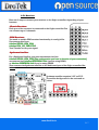
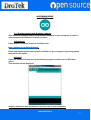
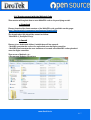
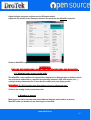
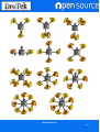
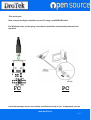
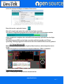
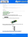
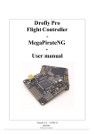
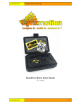
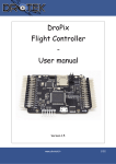
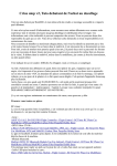
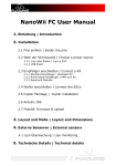
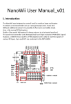
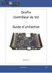
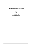
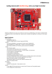
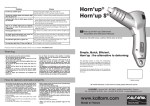
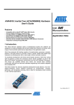
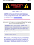
DROFLY PRO V3
User Guide
www.DroTek.fr
1/17
Table Of Contents
1/ INTRODUCTION
1.1/ Presentation
1.2/ Changes
2/ HARDWARE SETUP
2.1/ Setup on your frame
2.2/Connecting Flight Controller
a. To BEC
b. To Receiver
c. To Motors
2.3/ Enable LiPo
3/ SOFTWARE SETUP
3.1/ Getting started with Arduino Software
a. Download
b. Install
3.2/ Getting started with the Multiwii Code
a. Download
b. Install
3.3/ Multiwii code setup: config.h file
a. Number of motors
b. Flight Controller Selection
3.4/ Uploading Multiwii code into Flight Controller
3.5/ Using Multiwii GUI
3.6/ SD card
4/ ADDICTIONAL MODULES
4.1/ GPS+HMC
4.2/ Bluetooth
www.DroTek.fr
2/17
INTRODUCTION
1.1/ Presentation
MultiWii is an open source program's original author is a French program Alex,
Alex, after
severals years of joint efforts of many enthusiasts, and now this board has become
increasingly mature, has become very popular abroad, cost-effective flight control one.
That multi-axis aircraft MWC fans can easily access the high cost of this product,
through the MWC program to control the hardware platform, can achieve a variety of
multi-spindle, high-quality flight results, flexibility can be adjusted into a very stable or
very flexible to fit aerial, FPV or stunt flying and many different needs.
Compared to KK or ACM, MWC's more stable flight performance, flight skills required
for novice lower debugging process more intuitive.
Dedicated MultiWii GUI program can easily observe the PID parameters, flight control
signal input / output status, sensor / switch-state, as well as aircraft attitude and heading
sensor signal state of each group, sufficient for the initial configuration of the aircraft
easier.
MultiWii now supports multiple sensors and IMUs.
More information available here: http://www.multiwii.com/
Even if using MultiWii is simple, even for a beginner, it requires a few hardware and
software initial tasks.
This user manual will guide you through the basic steps to get your model flying.
This section will explain how to edit, setup and upload the MultiWii code into your flight
controller.
1.2/ Changes
Here are the changes since DroFly Pro V2
DroFly Pro V2
HMC5883
Size : 50mm*50mm
DroFly Pro V3
SD port
Size : 58,5mm*50mm
Battery level control with solder bridge
Buzzer Output
www.DroTek.fr
3/17
HARDWARE
2.1/ Setup on your frame
First, you need to identify the front of your flight controller.
By default the front of the FC is like below:
Anyway, you can easily identify flight controller orientation using GUI.
2.2/Connecting Flight Controller
a. To BEC
Flight controller must be powered by ESC BEC (5V) or by UBEC (5V) on connector n°2,
3, 5, 6, 7, 8, 9, 10, like below:
www.DroTek.fr
4/17
b. To Receiver
Here are 3 ways to connect your receiver to the flight controller depending of your
harware:
-Classic Receiver:
Each port of the receiver is connected to the flight controller. You
can connect up to 8 channels.
-PPM Receiver:
You need to enable PPM receiver functionality in config.h file.
Uncomment this lines:
#define SERIAL_SUM_PPM
#define PPM_ON_THROTTLE
Your Throttle is now your signal.
-Spektrum Satellite:
For a Spektrum Satellite, you must uncomment the line:
#define SERIAL_SUM_PPM [The configuration you have in fonction of your transmitter]
uncomment line #define SPEKTRUM 1024 if you’re using DSM2,
or #define SPEKTRUM 2048 if you’re using DSMX.
Then connect the Spektrum satellite to the dedicated port of the flight controller like
below:
Spektrum satellite requires 3.3V on VCC.
The solder bridge need to be activated as
below:
www.DroTek.fr
5/17
c. To ESC
MultiWii code can handle various types of flying models with different number of
motors and servos.
Please refer to section 3.3.b to identify which type of model you’re flying then connect
ESCs accordingly to the flight controller.
DEFAULT CONFIGURATION
2.3/ Enable LiPo
You can select your own level battery on the board with these solder bridges.You will
connect the center and the side you want. The objective is control the battery level and
warn you when it is too low.
For select S3, solder as below :
You need to modify these lines, you can find them in config.h.
config.h.
www.DroTek.fr
6/17
SOFTWARE SETUP
ARDUINO
3.1/ Getting started with Arduino software
This section will explain how to setup Arduino software on your computer in order to
edit and upload the Multiwii Code as you want.
a.Download
Latest Arduino software version is available here:
http://arduino.cc/en/Main/Software
Select and download the latest version available for your computer/operating system
then extract the zipfile.
b.Install
Open the extracted folder and Open Arduino program (arduino.exe for Windows
users).
This window will be displayed.
Arduino software is now installed and ready to use on your computer.
www.DroTek.fr
7/17
3.2/ Getting started with the Multiwii Code
This section will explain how to tune MultiWii code to fit your flying model.
a. Download
Please download the latest version of the MultiWii code available on this page:
http://fernitronix.fr/component/attachments/download/24
The downloaded file should be named as follow:
"MultiWii2.3_DroflyProV3.zip"
b. Install
Extract it in a dedicated folder; 2 subfolders will be created:
- MultiWii contains the code to be uploaded onto the flight controller
- MultiWiiConf contains the user interface to be used once MultiWii code uploaded
onto the flight controller.
Then move « Multiwii » in :
« Documents/Arduino/libraries »
www.DroTek.fr
8/17
Open Arduino program (arduino.exe
(arduino.exe for Windows users).
Open the File menu, in the Examples section. You must see the MultiWii in the list.
Click on MultiWii it opens the full project code.
WARNING
BEFORE ANY HANDLING, MAKE SURE THE PROPELLERS ARE REMOVED.
3.3/ Multiwii code setup: config.h file
The MultiWii code is splitted in several files, displayed in different tabs in Arduino. Each
one of them is dedicated to a specific functionality (sensors, GPS, LCD screen, etc…).
config.h is the parameters file to be edited in order to fit your flying model.
WARNING: Do NOT modify other files unless you’re an advanced user.
Click on the config.h tab to enter the code.
a. Number of motors
Multicopter models can take numerous different designs and number of motors.
MultiWii code can handle all the listed types of models:
www.DroTek.fr
9/17
www.DroTek.fr
10/17
Identify the type of model you need then uncomment the relevant line in the code (just
remove “//” at the beginning of the line).
Example, for a quadricopter X (2 front motors, 2 rear motors):
b. Flight Controller Selection
Now, you need to select the type of flight controller you are using.
Uncomment the #define DROTEK_DROFLY_V3 line.
www.DroTek.fr
11/17
The MultiWii code is now ready to be uploaded into your flight controller.
Please note this user manual describes only the basics of MutliWii code. Additional
parameters ( rx type, gimbal parameters, etc…) can be fine-tuned in the config.h file.
Please refer to the MultiWii FAQ for more details: http://www.multiwii.com/faq
3.4/ Uploading Multiwii code into Flight Controller
In order to compile and upload the code into the flight controller, you need to select :
-The type of board:
In Arduino program: Tools>>Board>>Arduino Mega 2560
www.DroTek.fr
12/17
-The serial port
Now, connect the flight controller to your PC using a miniUSB-USB cable.
For Windows users, on first plug, a new device should be automatically detected and
installed.
FC
PC
Once the message “device
“device successfully installed and ready to use”
use” is displayed, you can
www.DroTek.fr
13/17
select the relevant COM port in Arduino Tools menu:
Now click on the « upload » button:
This will compile and upload the code into the flight controller.
You can see compilation progress bar at the bottom-right of the Arduino window.
Once compilation complete, the code will be automatically uploaded into the flight
controller.
The red and green LEDs on the flight controller will blink rapidly until “Done
uploading” message appears at the bottom-left of the window. Your board is updated.
3.5/ Using Multiwii GUI
MultiWii code comes with a GUI (Graphical User Interface) which helps the user to
setup:
-sensors recognition, accelerometer/compass calibration , PIDs, rx channels
Download and informations:
https://code.google.com/p/multiwii/downloads/list
www.DroTek.fr
14/17
3.6/ SD card
DroflyProV3 used a SD card as datalogger.
This is an option and you can fly without the card or without the fonction activated.
During the flight, the card memorize :
-Differents warnings (level battery, i2c, failsafe..)
-Flight data (time in flight, time of operating, number of starts...)
-GPS coordinates of the UAV at regular intervals.
This allows after a flying session to analyze flight data and trace the path of such drone
on Google Earth.
After all, you need to download the follow library:
http://fernitronix.fr/documents/DroflyProv3/sdfatlib20131225.zip
Move it in the Arduino library folder.
You should be have it now :
In config.h,
config.h, uncomment:
www.DroTek.fr
15/17
#define LOG_PERMANENT 4096
#define MWI_SDCARD // activation of sdcard functionnality, needed for other defines
underneath
#define SDCARD_LOGGER // Logging of permlog and gps if available
#define LOG_PERMANENT_SD_ONLY // Disable permanent logging on eeprom
#define LOG_GPS_POSITION 2 // Write GPS position to log. Parameter is the number
of seconds between two logs
Upload the code.
Then you need a soft to process files between SD card and Google Earth.
The Soft is available here : http://rcnet.com/manuels/RCNet/RCNetDT.V091.zip
It should be named as “ KmlConverter” (Requires Java)
The Datalogger is activated ONLY when the motors are armed.
SD card needs to be formated in FAT before use.
4/ ADDICTIONAL MODULES
4.1/ GPS+HMC
You can connect a serial GPS module to the serial port 2 of the Drofly Pro V3.
With our Ublox GPS Module with his HMC5883(magnetometer), you have to
uncomment the lines below.
The code is simplified to allow to be understood by everyone.
everyone.
Make sure you've uncomment these lines in config.h.
www.DroTek.fr
16/17
#define GPS_SERIAL 2
Defines the serial port number of the GPS.
#define GPS_BAUD 57600
Defines the speed of GPS.
#define UBLOX
Defines your GPS. (Ublox with the kit “Drofly Pro V3 + GPS”)
The GPS baud must be equal to the Drofly config. Otherwise it dosen't work.
4.2/ Bluetooth
Drofly Pro V3 can receive a Bluetooth module as previous version.
Bluetooth connection is used for get a feedback of data during the flight, mainly.
You can plug a Bluetooth module on this port:
You can easily config your PID with the Android application available here:
https://play.google.com/store/apps/details?id=com.ezio.multiwii&hl=fr
www.DroTek.fr
17/17