1
DT800 Demonstration
Sensor Simulation Panel
Operating Instructions
#
Table of Contents
1. Introduction...................................................................................................................... 4
2. Installing the Sensor Simulation Panel ........................................................................... 4
3. A Quick Tour ................................................................................................................... 8
4. Powering the SSP ........................................................................................................... 9
5. DeTransfer Examples: .................................................................................................. 10
5.1 Potentiometer 1...................................................................................................... 10
5.2 Potentiometer 2...................................................................................................... 10
5.3 Potentiometer 3...................................................................................................... 10
5.4 Speaker / Microphone ............................................................................................ 11
5.5 Light Sensor ........................................................................................................... 11
5.6 Ruler................................................................................................................. 11, 12
5.7 Serial Data Channel .......................................................................................... 12,13
5.8 Digital Inputs .......................................................................................................... 13
5.9 Digital Outputs........................................................................................................ 13
5.10 Relay .................................................................................................................... 13
5.11 Flexible Tongue.................................................................................................... 14
5.12 Analog Output ...................................................................................................... 15
5.13 Thermocouple ...................................................................................................... 15
5.14 Scan Schedules ................................................................................................... 15
5.14.1 Polled .......................................................................................................... 15
5.14.2 Real Time.................................................................................................... 16
5.14.3 Digital Events .............................................................................................. 16
5.14.4 Counter Events ........................................................................................... 16
5.14.5 While Digital Event...................................................................................... 16
5.14.6 Change of CV.............................................................................................. 16
5.15 Alarms .................................................................................................................. 17
6. DeLogger4 Examples:................................................................................................... 18
6.1 Potentiometer 1...................................................................................................... 18
6.2 Potentiometer 2...................................................................................................... 18
6.3 Potentiometer 3...................................................................................................... 18
6.4 Speaker / Microphone ............................................................................................ 19
6.5 Light Sensor ........................................................................................................... 20
6.6 Ruler....................................................................................................................... 21
6.7 Serial Data Channel ............................................................................................... 22
6.8 Digital Inputs .......................................................................................................... 23
6.9 Digital Outputs.................................................................................................. 23, 24
Page 2
#
Table of Contents
6.10 Analog Output ...................................................................................................... 24
6.11 Thermocouple ...................................................................................................... 25
6.12 Scan Schedules ................................................................................................... 25
6.12.1 Polled .......................................................................................................... 25
6.12.2 Real Time.................................................................................................... 25
6.12.3 Digital Events .............................................................................................. 26
6.12.4 Counter Events ........................................................................................... 26
6.12.5 While Digital Event...................................................................................... 26
6.12.6 Change of CV.............................................................................................. 27
6.13 Alarms .................................................................................................................. 28
7. Further Help and Support.............................................................................................. 29
Page 3
#
1.
Introduction
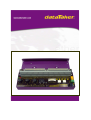
The dataTaker DT800 Sensor Simulation Panel (SSP) provides a number of different analog and
digital inputs and outputs for the DT800.
The Sensor Simulation Panel can be used for a variety of purposes including, but not limited to,
• Evaluating suitability of the dataTaker for particular applications, sensors and signal
combinations
• As a source of test inputs and outputs during the development and testing of dataTaker
programs and calculations procedures
• As a source of test inputs and outputs during the development and testing of applications
software for a host computer supervising the dataTaker
• For teaching the principles of data acquisition, process control, system monitoring, data
capture and transfer, etc. in educational institutions
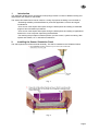
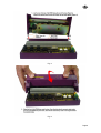
2.
Installing the Sensor Simulation Panel
The SSP replaces the DT800 terminal assembly. The SSP is installed on the DT800 as follows
Fig. 1.
Fig. 2.
Page 4
#
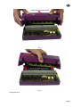
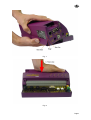
Fig. 3.
Fig. 4.
Closing the case
Page 5
#
Fig. 5.
Fig. 6.
Page 6
#
Fig. 7.
Fig. 8.
Page 7
#
Fig. 9.
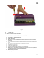
3.
A Quick Tour
The SSP has the following sensors and actuators
•
Potentiometer 1 – variable voltage, current or current loop
•
Potentiometer 2 – variable resistance
•
Potentiometer 3 – variable RTD simulator
•
Speaker / Microphone
•
Light Sensor – a silicon photodiode which outputs a voltage and current proportional to
ambient light
•
Ruler – configured as a full bridge, in which 2 halves of the ruler are two active arms of the
bridge
•
DB9 connector for serial data channel, configured as a PC COM1
•
2 push buttons – digital inputs
•
5 yellow LEDs –digital outputs
•
Single pole changeover Relay (under pcb) and 2 terminal block
•
Flexible tongue – configured as a full bridge, where fine copper tracks on the topside and
underside of the tongue are two active arms of the bridge
•
Magnetic pickup on the tongue
•
Analog output LEDs
Page 8
#
The SSP uses analog input channels 1 through 6, and digital channels 1 through 8. These channels
are indicated with a heavy border on the terminal block legend, and cannot be used to connect
external sensors to the logger while the SSP is attached.
Analog channels 7 through 12, digital channels 9 through 16 and the serial data channel are not used
by the SSP, and therefore can be used to connect external sensors to the logger while the SSP is
attached.
It is suggested that you connect the thermocouple originally supplied with the DT800 to analog input
channel 6 to complete the sensor set.
4.
Powering the SSP
Several of the sensors and actuators on the SSP require power, which is supplied by the DT800. Two
power supplies are used, the 5 VDC sensor power supply provided on terminal Sp, and the 12VDC
serial data channel power supply provided on terminal Serial 12V.
These power supplies are turned on by the DT800 commands
P47=5
1SSPWR=1
Most of the sensors and actuators require one or other of the power supplies, however it is simplest to
always have both power supplies enabled at all times when using the SSP.
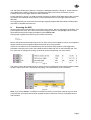
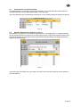
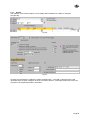
These two commands can be entered directly into DeTransfer text programs. In DeLogger4 the
parameter command can be set in the DT800 program builder and click on the Parameter tab. The
P47 value can be changed by clicking on the down arrow and selecting one of the values
Fig. 9.
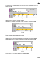
The sensor power value should be set by clicking on the Immediate tab in the DT800 program builder
window. Then enter a User channel type and typing in the serial sensor power command.
Fig. 10.
Note: If you send a RESET or FORMAT command or perform a push button reset at any time while
using the SSP, this will turn these power supplies off and so affect the function of powered sensors
and actuators.
Page 9
#
5.
Using the SSP with DeTransfer
This section briefly describes the use of each of the sensors and actuators on the SSP. The sample
programs can be run from DeTransfer. The DeTransfer programs can either be typed into the send
window, copied and pasted from this document, loaded directly from the CD ROM or copied from the
CD ROM to the DeTransfer sub-directory C:\Program Files\Datataker\Detransfer.
To open a command file in DeTransfer, Click on File and select Open from the drop down menu. In
the file selection dialog box select the path to where your files have been saved and open the
appropriate command file.
5.1
Potentiometer 1 (Labelled 1V, 1+V, 1+L)
This potentiometer is connected to analog input channel 1, and produces the following signals on the
terminals (ranges are approximate)
•
1V
a variable voltage in the range of 0 to 1800 mV
•
1I
a variable current in the range 0 to 18 mA
•
1+I
a variable current in the range 4 to 20 mA
•
1+L
a variable current loop in the range 0 to 100 %
These inputs can be read by the following DeTransfer program. (Prog1.dxc)
BEGIN”Pot_1”
P47=5
RA1S
1V
1I
1+I
1+L
END
5.2
Potentiometer 2 (Labelled 3R)
This potentiometer is connected to analog input channel 3 as a 4 wire resistance input, and produces
a variable resistance in the range approximately 0 to 500 Ohm.
The potentiometer resistance can be read by the following DeTransfer program. (Prog2.dxc)
BEGIN”Pot_2”
RA1S
3R(4W)
END
5.3
Potentiomener 3 (Labelled 4PT385)
This potentiometer is connected to analog input channel 4 as a 4 wire RTD input, and produces a
variable temperature in the range approximately -20 to 200 deg C.
The RTD resistance and corresponding ‘temperature’ can be read by the following program.
(Prog3.dxc)
BEGIN”Pot_3”
RA1S
4R(4W)
4PT385(4W)
END
Page 10
#
5.4
Speaker / Microphone (Labelled 1*V 7C(LT))
The speaker / microphone is connected to analog terminal 1* and digital input 7.
A signal waveform can be captured from the microphone by the program (Prog4.dxc)
BEGIN"Mic_1"
RA;BURST(100,10000,LEVEL,50,5S)
1*VNC(LEVEL>10,GL50MV,FF5)
END
Tap the microphone sharply with your finger or a pencil.
An analog frequency and digital frequency from the microphone can also be read by the program.
(Prog5.dxc)
BEGIN”Mic_2”
RA100T
1*F
7C(LT)
END
Tap the microphone sharply with your finger or a pencil.
The resistance of the speaker coil (nominally 8 Ohm) can be read by the program. (Prog6.dxc)
BEGIN”Mic_3”
RA500T
1*R
END
This repeatedly outputs an excitation current into the speaker coil, which will also drive the device as a
speaker producing a soft beep when each reading is taken.
5.5
Light Sensor (Labelled 5V)
The light sensor is a silicon photodiode which outputs a voltage and current proportional to the
ambient light intensity. The light intensity can be read by the program. (Prog7.dxc)
BEGIN”Light”
RA1S
5V
5I
END
Shade the sensor, or shine brighter light onto it, to change the readings.
5.6
Ruler (Labelled 6BGI)
The ruler along the front edge of the SSP configured as a resistance bridge, in which 2 halves of the
ruler are two active arms of the bridge.
Connect a flying lead wire to the + terminal of analog channel 6, and touch the other end onto the
white markings along the ruler while running the program. (Prog8.dxc)
BEGIN”Ruler”
RA1S
6BGI
END
Page 11
#
Initially the channel will read approximately –8000 ppm when not touching the flying lead onto the
ruler.
•
touch the flying lead onto the 0 marking, and the reading will be around –300 ppm.
•
touch the lead onto the 100 marking, and the reading will be around 300 ppm.
•
touch the lead onto the 50 marking, and the reading will be around 0 ppm.
The readings can be scaled to the 0 to 100 range of the ruler by the span. (Prog9.dxc)
BEGIN”Ruler_2”
S1=0,100,-300,300 "Units"
RA1S 6BGI(S1)
END
Touch the flying lead at various markings along the ruler and read the position.
The span can be set more accurately for your SSP by setting the lower and upper signal values to the
actual readings produced by your SSP when the 0 and 100 markings are touched respectively.
5.7
Serial Data Channel (Labelled Serial Sensor RS232)
The SSP provides a 9 pin D connector for the RS232 function of the serial data channel of the DT800.
This connector is configured the same as a COM port of a PC viz
•
pin 2
Receive
•
pin 3
Transmit
•
pin 7
RTS
•
pin 8
CTS
and so RS232 devices that can be connected to a PC can be connected to the SSP using the same
cable. The SSP does not provide any serial sensor simulation.
However the serial data channel could be demonstrated by connecting an RS232 serial dot matrix or
ticket printer to the SSP, or a PC running a terminal program such as DeTransfer or HyperTerminal,
and running the following program. (Prog10.dxc)
BEGIN”Serial_1”
‘Set serial channel baud rate to match printer or terminal
PS=9600,N,8,1,NOFC
RA10S
1SERIAL(RS232,”{DT800 Serial Sensor Port\\13\\10}”,W)
END
which will print the message every 10 seconds.
Page 12
#
Similarly a dataTaker 500 series data logger could be connected to the SSP (make sure that the
DT500 series logger is reset and in default data format), and read the voltage on channel 1 of the
logger by the program. (Prog11.dxc)
BEGIN"Serial_2"
PS=9600,N,8,1,SWFC
1SERIAL(RS232,"\\e{/e\\013}",W)
RA5S
1SERIAL(RS232,"{1V\\013}",W) ‘Request voltage on ch 1
DELAY(W)=2000
1SERIAL(RS232,"%2s[1$]\\013\\010%f[1CV]\\e",W,10)
1$
‘Command echo
1CV(FF3) ‘Returned voltage reading
END
5.8
Digital Inputs (Labelled 1DS and 2DS)
The SSP has two push buttons, connected to digital input channels 1 and 2 respectively. The state of
the push buttons, and the number of pushes, can be read by the program. (Prog13.dxc)
BEGIN”Push”
P47=5
1SSPWR=1
RA1S
1DS 1C
2DS 2C
END
5.9
Digital Outputs
The SSP has LEDs connected to digital channels 3 and 4 to indicate the output state of these
channels. The channels are turned on the commands
P47=5
1SSPWR=1
3DSO=0
4DSO=0
and turned off by the commands
3DSO=1
4DSO=1
5.10
Delay
The SSP has a single pole relay and LED connected to digital channel 5, which can be turned on the
the commands
P47=5
1SSPWR=1
5DSO=0
and turned off by the command
5DSO=1
The relay has a terminal block with Common, Normally Open and Normally Closed terminals, for
connecting external devices to be switched.
Page 13
#
5.11
Flexible Tongue (Labelled 2BGI, 8C(LT) 5*V)
The SSP has a flexible tongue along the front edge, which has fine copper tracks on both the topside
and underside of the tongue that are configured as two active arms of a bridge.
The strain on the tongue as the tongue is depressed can be read by the program. (Prog14.dxc)
BEGIN”Tongue_1”
RA500T
2BGI
END
The strain will increase from approximately 3500 to 3540 ppm as the tongue is fully depressed. The
strain on the tongue can be zeroed or tared as follows (Prog14.dxc)
BEGIN”Tongue_2”
2BGI(=1CV,W)
RA500T
2BGI(=2CV,W)
3CV(“Change =”)=2CV-1CV
END
The tongue also has a coil (in blue block) on its free end, immediately adjacent to a fixed coil (also in
blue block). When the coil on the tongue is energised, its magnetic field influences the fixed coil. If the
tongue is depressed then released smartly so that it vibrates, then these coils can be used as a
magnetic pickup to measure the vibration either as:
•
an analog frequency (Prog15.dxc)
BEGIN”Tongue_3”
RA500T
5*F
END
•
a digital count (Prog16.dxc)
BEGIN”Tongue_4”
RA500T
8C(LT,R)
END
Page 14
#
5.12
Analog Output
The SSP has two LEDs connected to the analog output channel. The yellow LED indicates positive
analog output voltages, while the green LED indicates negative analog output voltages.
The analog output can be set by the command
VO=level
where level is in millivolts in the range –10000 to 10000mV.
For example the command
VO=5000
will turn the yellow LED on to approximately half intensity, while
VO=-5000
will turn the green LED on to approximately half intensity. (Prog16.dxc)
BEGIN”Output”
1CV=-10000
RA100T
VO=1CV
1CV=1CV+100
END
5.13
Thermocouple
If you connected the thermocouple supplied with the DT800 to analog input channel 7, then the
temperature can be monitored by the command. (Prog17.dxc)
BEGIN”Temp”
RA1S
7TK
END
5.14
Scan Schedules
The SSP can be used to demonstrate several of the scan schedule triggers available in the DT800 as
follows:
•
5.14.1 Poll trigger by host (Prog18.dxc)
BEGIN”Poll”
P47=5
1SSPWR=1
RAX
‘Schedule triggers when host sends XA command
1V 3R 4PT385 5V
END
Send X or XA command from host PC (DeTransfer) to scan schedule
Page 15
#
•
5.14.2 Realtime trigger (Prog19.dxc)
BEGIN”Time”
P47=5
1SSPWR=1
RA5S
‘Schedule triggers every 5 seconds
1V 3R 4PT385
END
•
5.14.3 Digital event trigger (Prog20.dxc)
BEGIN”Event”
P47=5
1SSPWR=1
RA1+E
‘Schedule triggers when digital input 1 goes high
1V 3R 4PT385
END
Press push button 1 to produce digital events
•
5.14.4 Counter event trigger (Prog21.dxc)
BEGIN”Counter”
P47=5
1SSPWR=1
RA2C(5)
‘Schedule triggers when counter 2 reaches 5
1V 3R 4PT385 5V 1..2DS
END
Press push button 2 to produce counts events
•
5.14.5 Trigger schedule only while digital state is true (Prog22.dxc)
BEGIN”While”
P47=5
1SSPWR=1
RA2S:1W
‘Schedule triggers only while digital 1 is true
1V 3R 4PT385
END
Press push button 1 to stop schedule scanning
•
5.14.6 Trigger schedule by change of value of a CV (Prog23.dxc)
BEGIN”While”
P47=5
1SSPWR=1
RA1CV ‘Schedule triggers when CV changes value
1V 3R 4PT385
END
Send 1CV=1 and 1CV=0 commands from host PC (DeTransfer) to trigger schedule
Page 16
#
5.15
Alarms
The features of the DT800’s alarms can be readily demonstrated on the SSP, for example
(Prog24.dxc)
BEGIN”Alarm”
P47=5
1SSPWR=1
RA1S
ALARM(1V>1000)3DSO”High Voltage ! ?c ? ?u @ #^M^J”
END
Increase and decrease the voltage by rotating potentiometer 1. The LED on digital channel 3 will
illuminate when the input voltage on channel 1 exceeds 1000mV. A message is also sent to the host
computer if the set point threshold is exceeded.
Page 17
#
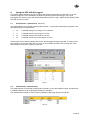
6.
Using the SSP with DeLogger4
This section briefly describes the use of each of the sensors and actuators on the SSP. To run the
example programs run the distribution CD ROM to load the project into DeLogger. Then open
DeLogger4 then click on Open and select DT800 SSP and click on open. Select the file named DT800
SSP.dlw and click on open
6.1
Potentiometer 1 (Labelled 1V, 1+V, 1+L)
This potentiometer is connected to analog input channel 1, and produces the following signals on the
terminals (ranges are approximate)
•
1V
a variable voltage in the range of 0 to 1800 mV
•
1I
a variable current in the range 0 to 18 mA
•
1+I
a variable current in the range 4 to 20 mA
•
1+L
a variable current loop in the range 0 to 100 %
These inputs can be read by loading and running the DeLogger program Prog1.dl8. To open and run
this program, from the DeLogger top menu bar, click on Window and then click on Prog1.dl8. Then
select Program and click on send to connection.
Fig. 11.
6.2
Potentiometer 2 (Labelled 3R)
This potentiometer is connected to analog input channel 3 as a 4 wire resistance input, and produces
a variable resistance in the range approximately 0 to 500 Ohm.
The potentiometer resistance can be read by loading the DeLogger program Prog2.dl8.
Fig. 12.
Page 18
#
6.3
Potentiomener 3 (Labelled 4PT385)
This potentiometer is connected to analog input channel 4 as a 4 wire RTD input, and produces a
variable temperature in the range approximately -20 to 200 deg C.
The RTD resistance and corresponding ‘temperature’ can be read by loading the program Prog3.dl8
Fig. 13.
6.4
Speaker / Microphone (Labelled 1*V 7C(LT))
The speaker / microphone is connected to analog terminal 1* and digital input 7. A signal waveform
can be captured from the microphone by the DeLogger program Prog4.dl8 This program takes 1000
samples at 100000 Hz. It also uses a level to start the burst sample taking 500 samples before the
trigger and 500 post trigger.
Fig. 14.
Tap the microphone sharply with your finger or a pencil. The wave form produces can be viewed by
the chart window.
Page 19
#
An analog frequency and digital frequency from the microphone can also be read by loading the
program Prog5.dl8
Fig. 15.
Tap the microphone sharply with your finger or a pencil.
The resistance of the speaker coil (nominally 8 Ohm) can be read by the program Prog6.dl8
Fig. 16.
This repeatedly outputs an excitation current into the speaker coil, which will also drive the device as a
speaker producing a soft beep as each reading is taken.
6.5
Light Sensor (Labelled 5V)
The light sensor is a silicon photodiode which outputs a voltage and current proportional to the
ambient light intensity. The photodiode output current and voltage can be read by Prog7.dl8
Fig. 17.
Shade the sensor, or shine brighter light onto it to change the readings.
Page 20
#
6.6
Ruler (Labelled 6BGI)
The ruler along the front edge of the SSP configured as a resistance bridge, in which 2 halves of the
ruler are two active arms of the bridge.
Connect a flying lead wire to the + terminal of analog channel 6, and touch the other end onto the
white markings along the ruler while running the DeLogger program Prog8.dl8
Fig. 18.
Initially the channel will read approximately –8000 ppm when not touching the flying lead onto the
ruler.
•
touch the flying lead onto the 0 marking, and the reading will be around –300 ppm.
•
touch the lead onto the 100 marking, and the reading will be around 300 ppm.
•
touch the lead onto the 50 marking, and the reading will be around 0 ppm.
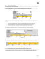
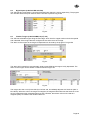
The readings can be scaled to the 0 to 100 range of the ruler by the span. Prog9.dl8
Fig. 19.
By selecting the scaling tab a span or polynomial can be entered to linearis and scale the data.
Fig. 20.
Touch the flying lead at various markings along the ruler and read the position.
The span can be set more accurately for your SSP by setting the lower and upper signal values to the
actual readings produced by your SSP when the 0 and 100 markings are touched respectively.
Page 21
#
6.7
Serial Data Channel (Labelled Serial Sensor RS232)
The SSP provides a 9 pin D connector for the RS232 function of the serial data channel of the DT800.
This connector is configured the same as a COM port of a PC viz
•
pin 2
Receive
•
pin 3
Transmit
•
pin 7
RTS
•
pin 8
CTS
and so RS232 devices that can be connected to a PC can be connected to the SSP using the same
cable. The SSP does not provide any serial sensor simulation.
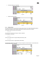
However the serial data channel could be demonstrated by connecting an RS232 serial dot matrix or
ticket printer to the SSP, or a PC running a terminal program such as DeTransfer or HyperTerminal,
and running the following program. (Prog10.dl8)
Fig. 21.
The program will print the message “Datataker DT800 Serial Sensor Port” every 10 seconds.
Similarly a dataTaker 500 range data logger could be connected to the SSP (make sure that the
DT500 series logger is reset and in default data format), and read the voltage on channel 1 of the
logger by the program. (Prog11.dl8)
Fig. 22.
This program requests the voltage on channel one of the connected DT500 and then waits for the
value to be returned.
Page 22
#
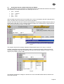
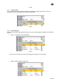
6.8
Digital Inputs (Labelled 1DS and 2DS)
The SSP has two push buttons, connected to digital input channels 1 and 2 respectively. The program
can read the state of the push buttons and the number of pushes Prog12.dl8
Fig. 23.
6.9
Flexible Tongue (Labelled 2BGI, 8C(LT) 5*V)
The SSP has a flexible tongue along the front edge, which has fine copper tracks on both the topside
and underside of the tongue that are configured as two active arms of a bridge.
The strain on the tongue as the tongue is depressed can be read by the program. Prog13.dl8
Fig. 24.
The strain will increase from approximately 3500 to 3540 PPM as the tongue is fully depressed. The
strain on the tongue can be zeroed or tared as follows Prog14.dl8
Fig. 25.
The tongue also has a coil (in blue block) on its free end, immediately adjacent to a fixed coil (also in
blue block). When the coil on the tongue is energised, its magnetic field influences the fixed coil. If the
tongue is depressed then released smartly so that it vibrates, then these coils can be used as a
magnetic pickup to measure the vibration either as:
Page 23
#
•
an analog frequency Prog15.dl8
Fig. 26.
•
a digital count Prog16.dlp
Fig. 27.
6.10
Analog Output
The SSP has two LEDs connected to the analog output channel. The yellow LED indicates positive
analog output voltages, while the green LED indicates negative analog output voltages.
The analog output can be set by the command
VO=level
where level is in millivolts in the range –10000 to 10000mV.
For example the command
VO=5000
will turn the yellow LED on to approximately half intensity, while
VO=-5000
will turn the green LED on to approximately half intensity.
The DeLogger program Prog17.dl8 puts a ramp volt output on the AO channel. You will observe the
intensity of the two LEDs changing.
Page 24
#
Fig. 28.
6.11
Thermocouple
If you connected the thermocouple supplied with the DT800 to analog input channel 7, then the
temperature can be monitored by the command. (Prog18.dl8)
Fig. 29.
6.12
Scan Schedules
The SSP can be used to demonstrate several of the scan schedule triggers available in the DT800 as
follows:
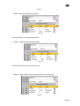
•
6.12.1 Poll trigger by host (Prog19.dl8)
Fig. 30.
Send X or XA command from host PC (DeLogger text window) to scan schedule
•
6.12.2 Realtime trigger (Prog20.dl8)
Page 25
#
Fig. 31.
•
6.12.3 Digital event trigger (Prog21.dl8)
Fig. 32.
Press push button 1 to produce digital events
•
6.12.4 Counter event trigger (Prog22.dl8)
Fig. 33.
Press push button 2 to produce counts events
•
6.12.5 Trigger schedule only while digital state is true (Prog23.dl8)
Fig. 34.
Page 26
#
Press push button 1 to stop schedule scanning
•
6.12.6 Trigger schedule by change of value of a CV (Prog24.dl8)
Fig. 35.
Send 1CV=1 and 1CV=0 commands from host PC (DeLogger text window) to trigger schedule
Page 27
#
6.13
Alarms
The features of the DT800’s alarms can be readily demonstrated on the SSP, for example
(Prog25.dl8)
Fig. 36.
Fig. 37.
Increase and decrease the voltage by rotating potentiometer 1. The LED on digital channel 3 will
illuminate when the input voltage on channel 1 exceeds 1000mV. A message is also sent to the host
computer if the setpoint threshold is exceeded.
Page 28
#
7.0
Further help and support.
For further information on DeTransfer text based programming environment please consult the
DeTransfer help file that is included as part of DeTransfer.
For further information on programming your dataTaker in the DeLogger graphical programming
environment please consult the User’s Manual, DeLogger4 and DeLogger4 Pro.
For details of the dataTaker programming language, wiring configurations and capabilities please
consult your dataTakers User’s Manual.
All software, manuals etc. for use with your dataTaker can be down loaded from our web page
www.dataTaker.com
If further technical support is required, please contact your local dataTaker dealer or our technical
support staff at the following email addresses.
Australasia and Asia Pacific region.
UK and Europe.
America, South America and Canada
[email protected]
[email protected]
[email protected]
Page 29