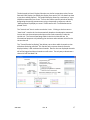
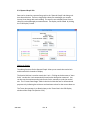
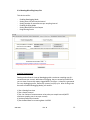
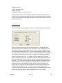
1
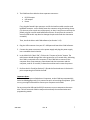
z User’s Manual June 11, 2015 P/N 998-3200 Revision B TURNER DESIGNS 845 W. Maude Avenue Sunnyvale, CA 94085 Phone: (408) 749-0994 FAX: (408) 749-0998 TABLE OF CONTENTS 1. Introduction 5 2. Inspection and Setup 2.1 Instrument Checklist 2.2 Optional Accessories 2.3 Setup and Cable Installation 6 6 6 6 3. ICAM Software 3.1 Software Installation and System Requirements 3.1.1 Minimum System Requirements 3.1.2 Software Installation 8 8 8 8 3.2 Operating Modes 10 3.3 Software Operation 3.3.1 Main Tab 3.3.2 Real Time Data Tab 3.3.3 Current Data Tab 3.3.4 Graph Tab 3.3.5 Spectral Graph Tab 3.3.6 Datalog & Profiling Setup Tab 3.3.7 Data Download Tab 3.3.8 Air Check Tab 3.3.9 Local Blank Tab 10 10 12 15 16 18 19 23 25 26 4. Operation 4.1 Functional Tests 4.2 Field Operation 28 28 31 5. Maintenance and Warranty 5.1 Maintenance 5.1.1 Cleaning and Care 5.1.2 Handling and Safety 5.1.3 Storage and Shipping 32 32 32 33 34 5.2 Warranty 5.2.1 Warranty Terms 5.2.2 Warranty Service 5.2.3 Out of Warranty Service 34 34 35 36 Appendices A. B. C. D. Product and Technical Specifications How to Determine Your Version of Windows OS ICAM Booster Operation Cleaning the ICAM with Ethanol 38 39 41 42 WASTE ELECTRICAL AND ELECTRONIC EQUIPMENT (WEEE) DIRECTIVE Turner Designs designs, manufactures, and sells products that enable the study, and benefit the well-being, of our natural world. Accordingly, we are concerned with helping to preserve the environment wherever our instruments are used and happy to work with our customers by complying with the WEEE Directive to reduce the environmental impact resulting from the use of our products. WEEE Return Process: To arrange the return of an end-of-life product, proceed as follows: If you purchased your instrument through a Turner Designs Distributor please contact your local representative. They will instruct you where to return the endof-life product. If you purchased your instrument directly from us please contact Turner Designs Customer Service: Phone: +1-408-212-4041 or Toll Free: +1 877-316-8049 Email: [email protected] We will provide you with a WEEE RMA Number, a Shipping Account Number, and a Shipping Address. Package and ship the product to the address provided. The product will be handled in an environmentally friendly manner according to our end-of-life recycling program. 1. INTRODUCTION ICAM, an in situ Integrating Cavity Absorption Meter, is factory-configured with nine (9) wavelengths ranging from UV (365nm) to red (676nm), enabling absorption measurements over a wide spectrum. ICAM’s patented integrating cavity design results in little to no effects from scattering particles, and is therefore superior to standard 180 degree absorption measurements. Built with solid-state optics and electronics, ICAM provides excellent reliability with low power requirements in a relatively small package. Absorption can be measured from 0.01 m-1 to 15 m-1. ICAM software can be used to collect data in real-time mode at a maximum rate of six (6) measurements per second. ICAM can also collect real-time data when in profiling mode at a maximum rate of six (6) measurements per second using ICAM profiling software. Profiling mode is necessary for real-time data capture at distances greater than the supplied interface cable. Another data collection method available, datalog mode, will log data internally at a maximum rate of one (1) measurement per second. All measurements will have a time stamp and up to nine (9) absorption values depending on the wavelengths selected. 998-3200 Rev. B 5 2. INSPECTION AND SETUP 2.1 Instrument Checklist The ICAM package includes: Integrating Cavity Absorption Meter instrument (P/N 3200-000) Interface cable that provides connection to power, USB, and RS-232 (P/N 3200-150) Pack of five (5) cleaning brushes and a cleaning rod (P/N 3200-550) Intake copper kit (P/N 3200-560) Power supply USB flash drive including ICAM software, driver installers, user’s manual, cable guide, and quick-start guide Two hose adaptor caps (for 3/8” hose) (P/N 3200-533) Note: We recommend saving the original packaging the ICAM is shipped in for the purpose of returns in case of damage or annual calibration. 2.2 Optional Accessories Submersible battery pack, charger, and cable (P/N 3200-600) 0.6m pigtail cable (P/N 2200-170) 10m extender cable (P/N 105-2595) 25m extender cable (P/N 105-2596) 50m extender cable (P/N 105-2597) Boosters required for >10m (P/N 2200-900) Replacement pack of five(5) cleaning brushes (P/N 3200-551) 2.3 Setup and Cable Installation 1. Remove the ICAM from its shipping box and place the instrument on a sturdy surface. The surface should be large and stable enough to support the full weight of the instrument (33 lbs./15 kg). Be sure the instrument does not roll off the surface. 2. Screw on the two hose adapter caps, one on either end of the ICAM, by turning each cap in a clockwise motion until tight. 998-3200 Rev. B 6 3. The ICAM interface cable has three separate connectors: RS-232 output USB output Power First, plug the female 8-pin connector end of the interface cable onto the male bulkhead connector on the ICAM; fasten the connector using the locking sleeve. (Tip: be sure to line up the two ends properly, as there is only one correct way the female plug fits onto the male bulkhead connector. Do not force the connector onto the ICAM as this may bend or damage the pins and render the instrument unusable.) Then, install the driver and ICAM software (see Section 3.1.2). 4. Plug the USB connector into your PC’s USB port and launch the ICAM software. 5. Connect the power connector to the power supply and plug the power supply into a standard electrical outlet. 6. In the ICAM GUI’s “Main Tab”, Click on the “Connect to Device” button. The radio button should change from red to green after a 15 second delay, indicating the ICAM is connected to the computer. If the ICAM fails to connect to the computer after a few attempts, power down both the instrument and the computer, wait 10-15 seconds, re-boot the machines and re-start the process. 7. Perform the Air Check(see Section 3.3.8) and the functional tests in Section 4.1 prior to operating the ICAM in the field. Important Notes: The order of the steps outlined above is important, as the ICAM may automatically switch to datalogging mode if it is powered on prior to launching the software. If this occurs, you might not be able to connect your computer to the ICAM. Do not connect the USB and the RS-232 connectors to your computer at the same time. This will cause the ICAM to malfunction and stop the communication and programming modes. 998-3200 Rev. B 7 3. ICAM Software 3.1 Software Installation and System Requirements ICAM software works with Windows-based systems. There is no Macintosh version available. 3.1.1 Minimum System Requirements Intel® Pentium® 133 MHz microprocessor Microsoft® Windows® 98 or higher 32 MB of RAM 800 x 600 SVGA resolution 3.1.2 Software Installation Included on the USB flash drive are: ICAM application Driver installer for 32-bit Windows OS Driver installer for 64-bit Windows OS Release Notes License Agreement 1. Exit all Windows programs and insert the USB flash drive. 2. If you’re running 64-bit Windows OS, double-click the CP210xVCPInstaller_x64.exe icon to install the correct driver for your operating system. If you’re running 32-bit Windows OS, double-click the CP210xVCPInstaller_x86.exe icon. If you’re not sure which OS your computer is running, please follow the instructions in Appendix B. 3. A screen will appear prompting you to begin the installation process. Click “Next.” 998-3200 Rev. B 8 4. Follow the screen prompts to install the driver software on your computer’s C drive. 5. You will see a “Completing the Installation of the CP210x USB to UART Bridge Driver” screen upon successful completion of installation. Click “Finish.” 6. Return to the USB flash drive window and open the ICAM_Application folder. 7. Double-click the “Setup.exe” icon. 8. Follow the screen prompts to install the ICAM GUI and supporting drivers, files, and folders. The GUI will automatically be installed on your computer’s C drive. If you wish to specify an alternate location for the installation, click the “Browse” button and type in the desired location. 9. Once the installation process is complete, restart the computer and locate the ICAM application icon on your desktop or in your applications folder. Note: If you have a previously installed version of the ICAM software, you will see the message “Existing Installed Instances Detected”. You can decide whether to install a new instance of the software or to maintain/update the previously installed version. Click “Next.” 998-3200 Rev. B 9 3.2 Operating Modes The ICAM operates in two distinct modes: Real Time and Datalog. Real Time Mode The Real Time mode enables you to collect real-time data using either the ICAM Software or ICAM Profiling software at a maximum data rate of six (6) measurements per second. Collecting real time data with ICAM software requires the ICAM to be connected to a computer via USB and therefore, distance is limited to the length of the interface cable. Collecting real-time data in Profiling Mode requires the ICAM to be connected to the computer using the RS232. Datalog Mode The Datalog mode allows for internal data logging. Users will set a start date and time, a sample interval, and the number of measurements to be recorded per sample interval. Data logged are simultaneously streamed as ASCII data via RS-232. The maximum data rate in this mode is one (1) measurement per second. See Sections 3.3.2 and 3.3.6 below for detailed information about the Real Time and the Datalog mode, respectively. 3.3 Software Operation The following sections describe the various screens, or tabs, of operation within the ICAM software. 3.3.1 Main Tab This tab is used for: - Connecting to ICAM Synchronizing ICAM date and time with computer Editing Channel Names Designating a directory where files will be saved Connecting to ICAM Upon launching the ICAM GUI software, the Connection Status radio button will be red. Plug in the USB connector to your PC, connect the power plug to the power supply, then click the “Connect to Device” button and wait at least 15 seconds. Once ICAM connects, the software radio button will turn green indicating the ICAM is connected to and communicating with the computer. 998-3200 Rev. B 10 When connected, the screen will display the date and time as abbreviated month, DD, YYYY; HH:MM:SS (e.g., Aug 8, 2013; 01:30:47). ICAM date and time The displayed date and time are representative of the current setting of the ICAM clock at the time of connection. To check ICAM’s date/time, click the “Get Device’s Current Date and Time” button, which will display ICAM’s current date and time. We strongly recommend synchronizing the clock of the ICAM with your computer’s date and time at least once, preferably the first time you run the software. This is accomplished by clicking the “Sync ICAM Date/Time with PC” button. 998-3200 Rev. B 11 Channel Names Channels can be renamed by typing into the channels’ text box. A maximum of 16 characters can be used to name a channel. If channels are renamed, the following message will be displayed: ‘Channel names were edited. Click Apply Changes to save Channel Names.’ After clicking “Apply Changes”, the channel names will be saved and displayed in all tabs and logged files. Note: The Main Tab is the only tab where channel names may be edited. Datalog Directory The field labeled “Results Directory” displays the directory path where data files will be saved. The default path for this location is your computer’s C drive. To change this location click the “Browse” button and navigate to the directory of your choice. 3.3.2 Real Time Data Tab This tab is used for: - Setting the sampling interval Setting the number of samples per sampling interval Selecting channels to measure Initiating data collection 998-3200 Rev. B 12 Setting the Sampling Interval To set the sampling interval, begin by choosing either second, minute, or hour from the “Sample Interval Unit” pulldown menu. Then enter a number that represents the time interval at which the ICAM will collect data in the box to the right of “per”. Finally, enter a number in the box to the right of Data Line(s) that represents how many measurements should be taken at the set time interval (see example below). The example below shows the settings for five readings at a 30 second sample interval. Note: The maximum sampling rate allowed is 6 measurements per second. 998-3200 Rev. B 13 Real-Time Data Channels Channel names can only be edited in the Main Tab and not in the Real-Time Data tab. Channels can be activated/deactivated by clicking in the box to the left of a channel. An active channel will have a checkmark in the box next to the channel. All active channels will be displayed in the Current Data, Graph, and Spectral Graph tabs when data collection starts and data will be collected only for those active channels. Data from inactive channels will not be displayed or logged. Data Collection Clicking the “Collect Data” button will begin data collection and the ICAM will be measuring samples at the set measurement rate. All fields will be grayed out and the “Stop Data Collection” button will be active. To view the data collected, use the following three tabs: Current Data (Section 3.3.3), Graph (Section 3.3.4), and Spectral Graph (Section 3.3.5). To stop measuring samples, click the “Stop Data Collection” button. A *.csv file will be saved to your computer containing all data from the time the “Collect Data” button was clicked. The “Results File” field displays the path where the file is being saved on the computer. It is for informational purposes only and cannot be modified. If you wish to change the file destination or folder designation you must do so in the Main Tab. Note: While in Real Time mode, the ICAM does not record data internally; all data stream from the instrument directly to the computer. 998-3200 Rev. B 14 3.3.3 Current Data Tab Tabular data are be viewed in the “Current Data” tab during real-time data collection. The display can be edited by clicking the “Edit Display” button.. Editing the Display Clicking on the “Edit Display” button will display the following box with various options for editing the tabular data view. The First Measurement Time and Last Measurement Time are for information only indicating how many samples and when the first and last samples were taken. 998-3200 Rev. B 15 There are three options for displaying data. If “Display Real Time Data” is checked, you can set the number of measurements to be displayed (maximum number of measurements displayed is 1000) and data will continue to stream but the screen will only update the set number of measurements to be displayed. For example, if 100 is set for Number of measurements to be displayed, you can only scroll through the most recent 100 measurements.. Any measurements taken after the 100th measurement will overwrite the displayed data, but data will not be lost as they are saved to a file. The other two options, “Display Data from(MM/DD/YYYY HH:MM:SS)” and “Display Data from this measurement” allow you to display data from a either a timestamp or a sequential data point. Note: For sampling intervals less than one second, data lines may be skipped in this display due to the lower resolution of the PC clock vs. the ICAM clock. 3.3.4 Graph Tab Graphical data can be viewed in the Graph tab during real-time data collection. The display can be edited by clicking the “Edit Graph Display” button. Editing the Display Clicking on the “Edit Graph Display” button will display the following box with various options for editing the graphical data view. 998-3200 Rev. B 16 The Horizontal Axis box's Display Selections are similar in operation to the Current Data tab's Edit Display (see Editing the Display from section 3.3.3 for details on how to use these editing options). The graphical display allows for a maximum of up to 10,000 measurements per screen. You can also look at specific periods of data by designating the starting measurement using a timestamp or sequence, and the “Measurements Displayed per screen” field as well as the “Total Measurements plotted” field.. The “Vertical Axis” box is used to rescale the Y-axis . Clicking on the box next to “Auto Scale” rescales the Y-axis automatically based on the absorption measured. You can also set the maximum and minimum axis limits manually to scale the vertical axis. The Current Data Range fields in the Vertical Axis box are for informational purposes only indicating the minimum and maximum values for the current data set. The “Traces(Checked to display)” box allows you to select which channels to view while data are being collected. This function only removes channels from the display window, it will not deactivate channels. Data for the non-displayed channels will still be logged and those channels are still active. The only way to deactivate a channel is from the Main Tab. 998-3200 Rev. B 17 3.3.5 Spectral Graph Tab Data can be viewed as a spectral bar graph in the “Spectral Graph” tab during realtime data collection. These are single point values per wavelength, per sample interval, that change with each reading. The axes are set to display meter inverse value for each wavelength per measurement. The display can be edited by clicking the “Edit Display” button. . Editing the Display The editing functions for the Spectral Graph allow you to rescale the vertical axis and choose which channels to display. The Vertical Axis box is used to rescale the Y-axis . Clicking on the box next to “Auto Scale” rescales the Y-axis automatically based on the absorption measured. You can also set the maximum and minimum axis limits manually to scale the vertical axis. The “Current Data Range” fields in the Vertical Axis box are for informational purposes only indicating the minimum and maximum values for the current data set. The Traces box operates in an identical way to the Traces Box in the Edit Display window of the Graph Tab (Section 3.3.4). 998-3200 Rev. B 18 3.3.6 Datalog & Profiling Setup Tab This tab is used for: - Enabling Datalogging Mode Setting start time and sample interval Setting number of measurements per sampling interval Enabling Profiling Mode Setting Baud Rate for Data Output Programming Device Enabling Datalog Mode Datalog mode allows for internal datalogging with a maximum sampling rate of 1 measurement per second. While data are logging, they are streamed via RS232 so you can view or externally capture logged data in real-time. A data file is generated for every datalogging event, defined by a power (on/off) cycle. After clicking in the box next to Enable Datalogging Mode, you need to: 1) Set a Datalog Start time 2) Set a Sample Interval 3) Set the number of measurements to be taken per sample interval (NOTE: maximum sampling rate is once per second) 4) Activate/Deactivate channels 5) Set the Baud Rate for streaming data via RS232 998-3200 Rev. B 19 6) Program Device 7) Click on the Main Tab 8) Click Quit ICAM 9) Disconnect Power and USB connection Make sure the USB is not connected to anything before powering up the ICAM. If the USB is connected when the ICAM is powered on, datalog mode will be disabled. You will need to enable datalogging mode again using the ICAM software using the steps outlined above. Set Datalog Start When you click the “Set Datalog Start” button, the following box will be displayed, There are multiple options for setting a Datalog Start time. Clicking the “Now” button will acquire the ICAM system time and write it to the “Datalog Start” field. Alternatively, you can use the “Beginning of:” and “On:” buttons and drop down menus to set the Datalog Start time. The next time the ICAM is powered, a power on sample will be recorded after ten seconds. The scheduled sample or samples will be recorded at the Datalog Start time plus a multiple of the designated sampling interval, 5 minutes in this case. For example, if the “Datalog Start” field reads 9:25:35, and you power up the instrument at 10:35:00, the power on sample time will be 10 seconds after that, at 10:35:10, and the scheduled samples will start at 10:35:35. If you power the instrument at 9:30:00, the power on sample will be 10 seconds after that, at 9:30:10, followed by scheduled samples at 9:30:35. If you power on to close to the scheduled samples, priority is given to the power up sample and as a result the scheduled samples will not be recorded until the next multiple of the sampling interval. To be sure your scheduled samples will be recorded, power the instrument 30 seconds ahead of a scheduled sample to allow time for the power up sample. After a Datalog Start time is set, click OK. 998-3200 Rev. B 20 Set Sample Interval When the Set Sample Interval button is clicked, the following box will be displayed, There are quick buttons for some sample interval selections on the left side of the display or you can set a specific sampling interval using the pulldown menus on the right side of the display. After a sample interval is set, click the OK button. Number of Measurements Enter a number in the box next to “Number of Measurements” to set how many measurements are made for each sampling interval. The maximum rate of sampling in datalog mode is 1 Hz. When the “Number of Measurements” value is more than one, samples will be separated by 1 second. Channel Selection Select the channels you want to be used for measurement. Data will be logged only for those channels that are selected. Baud Rate Selection Some users may want to view or capture data using third party loggers or a PC. Data logged will be simultaneously streamed as ASCII over the RS232 part of the cable Set the baud rate at which you want data to be streamed using the dropdown menu next to “Set Baud Rate for Data Output” 998-3200 Rev. B 21 Notifications Prior to Programming Device, you can see how much memory is available for logging through the Datalog memory status message. If there is enough memory for your logging event, continue by clicking “Program Device” when you're ready for the ICAM to accept and store the selected settings. After the settings have been stored you will receive a message that says, 'Datalog/Profiling parameters were successfully programmed.' You may now navigate to the Main Tab and Quit the ICAM Software. Important Notes Regarding Datalogging You must quit the software, power down the ICAM, disconnect it from your computer, and supply external power to the instrument in order for scheduled datalogging to begin. The ICAM will begin datalogging automatically on the scheduled start date and time. The ICAM will stop datalogging as soon as it is powered down. The next time the ICAM is powered up but not connected to a computer, it will start a new datalog session using the currently programmed settings. If it’s powered up while connected to the computer, no new datalogging session will begin. The ICAM will need to be programmed once again. Enabling Profiling Mode Profiling Mode is used for real-time data capture via RS232 at distances greater than the supplied interface cable. This mode requires using ICAM Profiling Software to collect data. The maximum sampling rate is 6 measurements per second. . To use the profiling mode, click the box next to “Enable Profiling Mode” and then click “Program Device”. Once the ICAM is programmed for profiling mode you will see the following message displayed, 'Datalog/Profiling parameters were successfully programmed.' You may now navigate to the Main Tab and Quit the ICAM Software. Open the ICAM Profiling Software and set up the ICAM for profiling. The tabs within the ICAM Profiling Software operate identically to the same tabs in the ICAM Software. For descriptions of the operation of the Main tab, Profiling Setup, Current Data, Graph, 998-3200 Rev. B 22 Spectral Graph, and Blank, see sections 3.3.1, 3.3.2, 3.3.3, 3.3.4, 3.3.5, and 3.3.9 respectively. 3.3.7 Data Download Tab This tab is used for - Downloading Data Saving Files to a Computer Erasing All Data Files from an ICAM Downloading Data Click the “Start Datalog Download” button to begin downloading all data files. . The progress bar will indicate the progress as well as how many files have been downloaded from the ICAM. Once downloading is complete, all files will be available for saving to the computer. The screen can allow up to 32,000 files to be downloaded at one time. You can scroll through the files using the Top, Next, Previous, and Bottom buttons in the bottom left hand corner of the screen. Files will be numbered 1-32,000 and will be displayed along with a starting and ending timestamp and the number of measurements in each file. There will be no file name associated with a file until 998-3200 Rev. B 23 that file is manually saved to the computer, at which point, file names will be displayed. Saving Files To save a file, double click in the “To Be Saved” box next to the file you would like to save. A green checkmark will be displayed in the box next to the file. Repeat this process for all files you wish to save. You may also click on the “Select All to Save” button to designate all files displayed to be saved. The other option for saving files is to click on the “Choose Data Sets to Save” button which will provide you with options for designating specific files to save. Hiding Files To hide a file, double click in the “To Be Hidden” box next to the file you would like to hide from the display. A red X will be displayed in the box next to the file. Repeat this process for all files you wish to hide. You may also click on the “Select All to Hide” button to set all files to be hidden. The other option for hiding files is to click on the “Choose Data Sets to Hide” button which will provide you with options for designating specific files to hide. Hidden files are not deleted from memory, they are simply hidden from view. You may unhide these files by clicking on the “Show All Data Sets” button. After you've finished designating files to either be saved or hidden, click the “Accept Selections” button to process your choices. Once processing has completed, you may click the “End Session” button to stop all functions on this screen. Clicking the “Erase All Data” button will permanently delete all data files so that they are not retrievable. Be sure you mean to delete all files from the ICAM before you select this option. 998-3200 Rev. B 24 3.3.8 Air Check Tab This tab enables you to perform a test to check the integrity of the ICAM's flow tube as well as signal for all 9 channels. Please make sure the instrument is at room temperature (25 ⁰ C) and the flow tube is properly cleaned and dried before running the Air Check. Click the “Air Check” button at the top of the screen. The air check takes about 2-3 seconds. If any of the radio buttons turn red, the flow tube has not been properly cleaned, in which case you should clean, dry, and run the air check again. Repeat this process up to 3 times and if results are similar for the three independent checks, call the manufacturer for support. See Section 5.1 for Maintenance and Cleaning recommendations. Note: We strongly recommend an air check as the first test prior to field use. We also recommend using the ICAM in the field only if the instrument fully passes the air check. Certain environmental and/or atmospheric conditions like humidity and condensation, while essentially harmless, may cause the Air Check to fail. In these cases, you should base your decision whether or not to employ the ICAM on the specific conditions of your research objectives. 998-3200 Rev. B 25 3.3.9 Blank Tab The Blank Tab allows you to measure a blank value from a solution or sample and Save or Load blank values from ICAM. The blank values measured at all 9 wavelengths are used by the ICAM software as an offset in the calculation of meter inverse. For example, if the channel 1 measured blank value is 0.004 m-1, that amount of absorption will be subtracted from the sample measurement for a blank corrected absorption. Get Blank Values In some instances, it is desirable to measure a local blank and use that measurement in calculations of absorption. This can be accomplished by loading the ICAM with the desired blank water, and pressing the “Get Blank Values” button. Be sure to clean the ICAM according to the instructions in Section 5.1.1 before measuring the local blank. Once the blank values are measured they can be used by the ICAM immediately by saving them to the instrument using the “Save Blank Values to ICAM” button. Alternatively, a user can save these blank values to a file for use later by pressing the “Save Blank Values to File” button. Load ICAM Blank Values This button will recall and display the current blank values being used by the ICAM. 998-3200 Rev. B 26 Load Blank Values from File In addition to measuring a blank, the ICAM can accept and store a local blank through use of a file. This file would have been acquired through the use of the “Save Blank Values to File” button. To load a local blank file, press the “Load Blank Values from File” button and navigate to the desired local blank file. Save Blank Values To ICAM After measuring a local blank with the “Get Blank Values” button, or loading a local blank with the “Load Blank Values from File” button, a user can begin using the local blank values in calculations of absorption by pressing the “Save Blank Values to ICAM” button. Save Blank Values to File After measuring a local blank, a user can save the local blank values to a file for later use. In order to save the blank values to a file, press the “Save Blank Values to File” button. Set Default Blank Values Sets blank values to 0 for all channels. 998-3200 Rev. B 27 4. OPERATION 4.1 Functional Tests Before using the ICAM in the field for the first time, we strongly recommend conducting a functional test in a controlled environment such as a laboratory or office. Setup for Functional Testing 1. Follow instructions for setting up the ICAM in Section 2.3. 2. Screw on the two hose adapter caps, one on either end of the ICAM, by turning each cap in a clockwise motion until tight. Attach a standard 3/8” (9.5mm) ID (inside diameter) water hose to each adapter cap. Note: Most plastic tubing will leach chemicals or other foreign elements into the water if the tubing is in contact with water for an extended period of time. This will contaminate samples and may interfere with the measurement.. If the instrument is to remain setup for measuring discreet samples for extended periods of time, we recommend using Norprene® tubing, natural color (not black), or any tubing that has very low to no leaching effects. We also recommend removing the hoses from the end caps and emptying any water left inside after each use. 3. For optimal results, bubbles should be purged from the flow tube to avoid interfering with the measurement: position the ICAM vertically with flow directed upward through the flow tube. If it is not possible to hold the ICAM in a vertical position securely, elevate the outflow end above the inflow end to prevent bubbles from building up inside the instrument. 4. Follow the instructions for the Air Check and the various Functional Tests below. Air Check The air check should be performed prior to conducting any functional tests or operating the ICAM in the field. 1. Connect the USB end of the ICAM interface cable to a USB port on your computer; be sure the RS-232 cable is not connected to the ICAM. 2. Launch the ICAM software. 3. Power on the ICAM. 998-3200 Rev. B 28 4. Click the “Connect to Device” button in the Main tab. The radio button should change from red to green, indicating the ICAM is connected to the computer. 5. Click on the “Air Check” tab and follow the instructions in Section 3.3.8. 6. If the Air Check is successful (i.e., all test indicators turn green), you may proceed to the functional tests below. If any of the indicators turn red, we recommend cleaning the ICAM and repeating the Air Check. See Section 5.1.1 for cleaning and maintenance. Note: Be sure to flow water through the ICAM for the following series of functional tests. These are not air tests. Real Time Mode Functional Test 1. Connect the USB end of the ICAM interface cable to a USB port on your computer; be sure the RS-232 cable is not connected to the ICAM. 2. The first time you conduct this test, be sure the ICAM software has been installed. For installation instructions, please see Section 3.1.2. Launch the ICAM software. 3. Power on the ICAM. 4. Click the “Connect to Device” button in the Main tab. The radio button should change from red to green, indicating the ICAM is connected to the computer. 5. Click on the “Real Time Data” tab. For the purposes of this test, the default values of 1 measurement every 1 second are sufficient. Click on the “Collect Data” button. At this point, a filename and path will appear in the “Results File” field and all other controls besides “Stop Data Collection” will be greyed out. Click on the “Current Data” tab. Tabular data should be streaming into the display at 1 sample/second. If these values are positive, they will appear on the Graph and Spectral Graph tabs as well. . 998-3200 Rev. B 29 Datalog Mode Functional Test 1. In the Datalog & Profiling Setup tab, click the “Set Sample Interval” button. Using the dropdown menu for “Seconds” under the “Number Of” heading, set the value to 2. Click on “OK”. Click on the “Set Datalog Start” button, a new window will open. Click on the “Now” button, then click the “OK” button. . 2. Check the “Enable datalogging” box and click the “Program Device” button. Take note the “Set Baud Rate for Data Output” field value should be 9600. Click on the Main tab, then click the “QUIT ICAM” button. Disconnect the USB cable from the computer, and disconnect the power cable from the ICAM. 3. In order to confirm operation of the RS-232 stream, plug the DB9 cable into a serial port on your PC. Open your preferred terminal program and associate that connection with the DB9. Setup the com port for a baud rate of 9600, 8 data bits, 1 stop bit, no flow control and no parity. When you power the ICAM, data should stream into the terminal window at the prescribed interval. . 4. Power the ICAM. The instrument will begin datalogging and streaming automatically according to the settings you configured in Step 1. 5. Once the datalogging process is complete, disconnect the power from the ICAM and the DB9 from the PC. Reconnect the USB cable to the computer and launch the ICAM software. Next, power on the ICAM again and click on the “Connect to Device” button. Click on the “Data Download” tab and follow instructions in Section 3.3.7 to download the data. . 998-3200 Rev. B 30 4.2 Field Operation The ICAM can be used on deck or in open water, individually or configured as part of a CTD rosette. In open water, it is permissible to operate the ICAM without hoses and pumps. Note: If you are using a pump to run water from a body of water up to the ship, please note that most pumps are limited in the maximum vertical distance they can deliver; check the limitations and recommended uses of your pump. Recommended Position We recommend operating the ICAM in a vertical position for optimal water flow and reading accuracy. A horizontal position may cause air bubbles to become trapped within the inner flow tube and interfere with proper readings. 998-3200 Rev. B 31 5. MAINTENANCE AND WARRANTY Important Note on Calibration of the ICAM The ICAM does not require regular user calibration. We do, however, strongly recommend that you ship the instrument back to us once a year for professional recalibration and maintenance. See Section 6.2 below for shipping instructions or contact Turner Designs customer service for more information. Phone: 1 (877) 316-8049 Email: [email protected] 5.1 Maintenance 5.1.1 Cleaning and Care Cleaning should occur pre and post deployment of the ICAM and can be carried out whether or not the instrument is powered on. Cleaning removes residue and buildup that occurs during normal operation. Because the device is extremely sensitive, it is not sufficient or recommended to rely on a simple visual check to determine whether the inner tube needs to be cleaned. Even minute or minimal residue invisible to the human eye can cause contamination, which in turn will affect the readings, especially on the lower end of the absorption range. Cleaning the ICAM: Exterior Housing Rinse the exterior housing of the ICAM with freshwater after each deployment. If the housing is excessively dirty, use a very mild solution of deionized water and household dishwashing liquid. Remove organic buildup or residue with a scrubbing pad. Note: Take extra care to ensure the dishwashing liquid solution does not enter the inner tube as residue may affect subsequent absorption measurements. Cleaning the ICAM: Flow Tube Assemble the ICAM cleaning rod by screwing together the two halves of the plastic handle. Ideally with laboratory gloves, slip the cleaning brush onto the metal post at the end of the rod. This will help decrease the chance of contaminating the brush. The brush should be able to turn freely around the post, but without slipping off. Remove the hose adapter caps from both ends of the ICAM. 998-3200 Rev. B 32 Dip the cleaning brush in deionized water. Run the brush through the inner tube back and forth several times. Pull the brush out, squeeze off excess water, and repeat until the brush absorbs no more liquid. If the inner tube is extremely dirty, clean with a mild solution of 98% deionized water and 2% household dishwashing liquid. Rinse VERY THOROUGHLY with deionized water and repeat the step above. If deposits are still present, refer to Appendix D: Cleaning the ICAM with Ethanol. Note: Any residue remaining in glass tube may affect absorption measurements. Note: Do not use chamois cloth, paper towels, or any other materials as they may scratch the glass of the inner tube. If the brush comes off inside the device, push it through to the other end using the brush handle. Note: Do not use metal or wood rods, or anything other than the plastic brush handle inside the glass tube. Performing an Air Check It is recommended that you run an air check following each cleaning. For instructions on how to run an air check, please see Section 3.3.8. 5.1.2 Handling and Safety Avoid back injury when lifting or moving the ICAM (the device weighs 33 lbs./15 kg). Use the rounded handles on either end of the device to lift or move the ICAM. Do not drop the ICAM as the inner glass tube can crack or shatter, leaving the instrument inoperable. In addition, a cracked or broken glass tube will render the device no longer waterproof. Avoid sudden impacts of any kind, whether dropping or striking the ICAM against other objects. Do not rest the ICAM on its end when the hose adapter caps are attached. This will damage the caps and the device. 998-3200 Rev. B 33 If you suspect the inner tube is cracked, broken, or otherwise damaged, please return the device to Turner Designs for inspection (Section 5.2.2 or 5.2.3). Do not attempt readings or measurements using water as this may further damage the instrument. Do not attempt to repair the ICAM yourself or via any third party. 5.1.3 Storage and Shipping You may store the ICAM horizontally or vertically. In either case, the device should be secured against movement by strapping or bracing it to a solid object. When storing the ICAM for long periods of time when it is not being used, we recommend placing it in its original shipping box. During long-term storage, access to the intake ends of the ICAM should be protected to prevent dust and other foreign materials from entering the inner tube. You can use the hose adapter caps for this purpose, but must take care to ensure the caps will not risk impact. IMPORTANT: Do not stand the instrument on its end with the hose adapter caps attached. This will damage the caps and the instrument. If you lose the original shipping container and the foam end supports for the ICAM, contact [email protected] and we will send you a replacement shipping container. Do not attempt to package the ICAM without adequate support for the instrument. 5.2 Warranty 5.2.1 Warranty Terms Turner Designs warrants the ICAM and its accessories to be free from defects in materials and workmanship under normal use and service for a period of twelve (12) months from the date of shipment from Turner Designs, with the following restrictions: Turner Designs is not responsible for replacing parts damaged by misuse, accident, or neglect. Your instrument must be installed according to the instructions provided in the User’s Manual. Damage caused by corrosion is not covered. Damage caused by customer modification of the instrument is not covered. 998-3200 Rev. B 34 Damages incurred during shipping and/or transport are not covered. This warranty covers only Turner Designs products and is not extended to equipment used with our products. We are not responsible for incidental or consequential damages, except in those states where this limitation is not allowed. This warranty gives you specific legal rights; you may have other rights that vary from state to state. 5.2.2 Warranty Service To obtain service during the warranty period, please follow these steps: 1. Write, email, or call the Turner Designs Technical Support Department and describe the nature of the problem as precisely as possible. Telephone (US): +1 877-316-8049 Email: [email protected] 2. Carry out any adjustments or tests as suggested by the Technical Support Department. If the above adjustments or tests do not resolve your issue and the ICAM does not perform properly, we will issue a Return Materials Authorization number (RMA) to you so that you may return the instrument to us for service. Package the instrument in the original shipping box, write the RMA number on the outside of the shipping carton, and ship the instrument, prepaid by sender, to Turner Designs (please see our shipping address below). If you lose the original shipping container and the foam end supports for the ICAM, contact us and we will send you a replacement shipping container. Do not attempt to package the ICAM without adequate support for the instrument. For customers within the contiguous continental United States: If the instrument failure is covered under the warranty terms, we will repair the instrument and return it to you free of charge. For customers outside the contiguous continental United States: If you purchased equipment from one of our authorized distributors, please contact your distributor. If you purchased directly from Turner Designs, contact us (see above). If the instrument failure is covered under the warranty terms, we will repair the instrument free of charge. You are responsible for shipping, duties, and 998-3200 Rev. B 35 documentation to Turner Designs. We will pay for return shipment; however, you are responsible for any custom duties, taxes and fees incurred on the return shipment. 5.2.3 Out-of-Warranty Service Follow the steps for Warranty Service as listed above. If our Technical Support Department can assist you by phone or correspondence, we will happily do so at no charge. If the issue you are experiencing cannot be resolved via telephone or correspondence, we will ask you to send the instrument to us for repair and provide you with an applicable RMA number. Repair service will be billed on a fixed price basis, plus any applicable duties and/or taxes. Shipment to Turner Designs should be prepaid. Your bill will include return shipment freight charges. Shipping Address: Turner Designs, Inc. 845 W. Maude Ave. Sunnyvale, CA 94085 998-3200 Rev. B 36 998-3200 Rev. B 37 APPENDIX A: SPECIFICATIONS INTEGRATING CAVITY ABSORPTION METER (ICAM) Weight in Air 15 kg (33 lbs.) Length 78.7 cm (31 in) Diameter 17.8 cm (7 in) Pressure Hull Titanium Type 2 End caps, Handles, Supports Acetal plastic Temperature -2 to 50C Humidity 0 – 90% (condensing) Depth 0 – 200 m DC Power Required 8 to 30 volts; 25 watts Signal Output Digital (ASCII) Interface RS-232, USB Minimum Sampling Interval Datalog: 1 Hz, Profiling: 6 Hz Nonvolatile Memory 64,000 data lines SUBMERSIBLE BATTERY PACK Battery Connector Weight in Air Weight in Water Length Diameter Material Temperature Depth Capacity Voltage Output Protection Features 998-3200 Lithium ion 8-pin 2 kg (4.41 lbs.) 0.72 kg (1.59 lbs.) 181mm (7.13 in) w/o connector 101.6mm (4.0 in) Delrin (Acetal plastic) 0 to 50C 0 – 600m 6600 MAHr 14.4 V (nominal) Protects against overcharge, over-discharge, overheating, short-circuits. Includes internal pressure relief. Rev. B 38 APPENDIX B: HOW TO DETERMINE YOUR VERSION OF WINDOWS OS Is my PC running the 32-bit or 64-bit version of Windows? The terms 32-bit and 64-bit refer to the way a computer's processor (also called a CPU), handles information. The 64-bit version of Windows handles large amounts of random access memory (RAM) more effectively than the 32-bit version. Follow the steps in the sections below to find out if your PC is running the 32-bit or 64-bit version of Windows and what edition of Windows is on your PC. Computers Running Windows XP Click Start, right-click My Computer, and then click Properties. If “x64 Edition” is listed under System, you’re running the 64-bit version of Windows XP. If you don’t see “x64 Edition” listed under System, you’re running the 32-bit version of Windows XP. The edition of Windows XP you're running is displayed under System near the top of the window. Computers Running Windows Vista or Windows 7 Click the Start button, right-click Computer, and then click Properties. If “64-bit Operating System” is listed next to System type, you’re running the 64bit version of Windows Vista or Windows 7. If “32-bit Operating System” is listed next to System type, you’re running the 32bit version of Windows Vista or Windows 7. The edition of Windows Vista or Windows 7 you're running is displayed under Windows edition near the top of the window. For more information about 32-bit and 64-bit Windows 7, see 32-bit and 64-bit Windows: frequently asked questions. http://windows.microsoft.com/enus/windows/32-bit-and-64-bit-windows#1TC=windows-7 Computers Running Windows 8 1. Open the Windows 8 Control Panel. Tip: You can check your Windows 8 system type much faster from the Power User Menu but it's probably speedier that way only if you're using a keyboard or mouse. With that menu open, click or touch on System and then skip to Step 4. 998-3200 Rev. B 39 2. Touch or click on System and Security within Control Panel. Note: You won't see a System and Security link in Control Panel if your view is set to either Large icons or Small icons. If so, find System and touch or click on it, then skip to Step 4. 3. With the System and Security window now open, click or touch System. 4. With the System applet now open, titled View basic information about your computer, find the System area, located under the large Windows 8 logo. The System type will say either 64-bit Operating System or 32-bit Operating System. Citation: “Is my PC running the 32-bit or 64-bit version of Windows?.” Microsoft Corporation. Viewed online on February 9, 2014 at : http://windows.microsoft.com/en-us/windows7/find-out-32-or-64-bit. Additional source: http://windows.microsoft.com/en-us/windows/which-operating-system 998-3200 Rev. B 40 APPENDIX C : ICAM BOOSTER OPERATION In order to view ICAM data in real-time over cables lengths greater than 10 meters, boosters are required (p.n. 2200-900). Instructions for installing boosters can be found at: http://www.turnerdesigns.com/t2/doc/instructions/998-2209.pdf Boosters are specific to the profiling application of the ICAM. When using boosters with the ICAM, you are required to use the RS-232 DB-9 connector end of the interface cable instead of the USB. You will also need to provide a power supply capable of outputting 15VDC at 1 Amp (alternatively, you can use a 100 amp-hour 12V deep-cycle marine battery). To set up the ICAM for profiling with boosters follow these steps: 1) Connect the wet mateable end of the interface cable (P/N 3200-150) to the ICAM. 2) Connect the USB end of the interface cable to a USB port on your computer. 3) Plug in the power connector of the interface cable to the ICAM power supply (P/N 159-0191). 4) Double click on the ICAM Software application. Connect to the ICAM with the “Connect to Device” button on the “Main” tab. 5) After the instrument connects, click on the “Datalog & Profiling Setup” tab. Click on the “Enable Profiling Mode” checkbox. Click on the “Program Device” button. In response, the software will state, “Datalog/Profiling parameters were successfully programmed”. Click on the “Main” tab, click on the “Disconnect Device” button, click on the “Quit ICAM” button. 6) At this point the ICAM is ready to profile and display data in real-time. For the profiling application, the sample interval is set to 1 per second and cannot be changed. 7) Power down the ICAM and disconnect the interface cable from the PC and the ICAM. 8) Assemble boosters according to the instructions found at the link above. 9) Connect the DB-9 end of the interface cable to a serial port on your PC. 10) Supply 15VDC to the power plug of the interface cable (or 12VDC from a deepcycle marine battery). Note: The ICAM power supply that shipped with your unit will not work for this purpose. 11) Double click on the “ICAM Profiling” application shortcut. Click on “Connect to Device” and wait until “Connection Status” is green and the software states “Device is now connected”. 12) Click on the “Profiling Setup” tab. Designate the number of samples per unit time. Maximum data rate is 6 samples per second. 998-3200 Rev. B 41 13) Click on the “Collect Data” button. The ICAM should immediately start collecting data. These data can be viewed in tabular form on the “Current Data” tab, or in graphical form on the “Graph” tab. APPENDIX D : CLEANING ICAM WITH ETHANOL In cases of heavy biofouling, you may need to clean the ICAM with a solvent. It is strongly recommended that you wear gloves during this procedure. 1) Remove the hose adapter caps from both ends of the ICAM. 2) Assemble the ICAM rod by screwing together the two halves of the plastic handle. 3) Pour about 10 mL of ethanol into a clean 64 oz. square tupperware. 4) Drop a new foam cleaning head into the tupperware and roll it around until it absorbs most of the alcohol. Wring out the ethanol back into the tupperware. 5) Install cleaning brush onto cleaning rod. 6) Run cleaning brush through the flow tube of the ICAM multiple times. 7) Remove cleaning brush and inspect. If the cleaning brush comes out with visible deposits, dispose of it and restart procedure at step 3 with a new cleaning brush. If cleaning brush comes out free of visible deposits, wrap foam head in a delicate task wiper(kim-wipe) and squeeze. The kim-wipe will absorb any remaining ethanol. Repeat this until the kim-wipe absorbs little to no ethanol. 8) Wrap the cleaning brush in a kim-wipe and run through flow tube on last time. Visual inspection of the flow tube should find a clean consistent finish with no moisture, streaks, or foreign matter. 998-3200 Rev. B 42