1
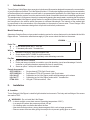
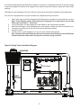
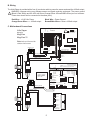
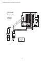
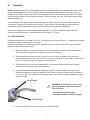
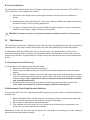
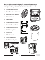
Manual Little Dipper Fluorometer by Turner Designs PTSA Trace Chemical Control Advantage Controls P.O. Box 1472 Muskogee, OK 74402 Phone: 800-743-7431 Fax: 888-686-6212 www.advantagecontrols.com email: [email protected] 1 6/2014 Little Dipper Fluorometer Instruction & Maintenance Manual Table of Contents Contents Page I. Introduction.................................................................................. 3 Model Numbering........................................................................ 3 II. III. IV. V. Installation................................................................................... 3 A. Location................................................................................. 3 B. Wiring..................................................................................... 5 C. Motherboard Connections..................................................... 5 Operation Overview..................................................................... 7 A. Initial Calibration.................................................................... 7 B. On Line Calibration................................................................ 8 Maintenance................................................................................ 8 A. Visual Inspection and Cleaning.............................................. 8 B. Maintenance Check Using Standard Solutions...................... 8 Warranty...................................................................................... 9 2 I.Introduction Turner Designs’ Little Dipper is an accurate, single-channel fluorometer designed to measure the concentration of your fluorophore of interest. The Little Dipper provides 4 - 20 mA output signal proportional to the concentration of the fluorophore in the sample or source water. In a representative application, the Little Dipper can be used with a data collection system to monitor and control the level of treatment chemicals in industrial applications. The sample water’s fluorescence intensity is measured by passing the sample water, containing the fluorophore of interest, past the Little Dipper’s optical window. An excitation light source illuminates the solution and excites the fluorophore in the solution which fluoresces at a different wavelength. The intensity of the emitted light is proportional to the concentration of the fluorophore in the sample or source water. Turner Designs’ Little Dipper has a low maintenance design that will provide trouble-free performance. Model Numbering Advantage Controls offers a unique model numbering system for various features to be included with the Little Dipper sensor. To determine what features apply to your sensor check the label on the sensor. LD2800A - ____ ____ ____ Probe Tee Q = Quick release probe with 1” PVC tee T = 1” threaded probe with 1” threaded tee Wiring 1 = Standard 4 conductor cable with stripped ends 2 = Quick release INPUT-CABLE-4 style connection. Includes factory pre-wiring to seperately order Advantage controller Pre-Fab X = Probe and tee not installed Y = Probe and tee pre-installed in controller or pre-fab plumbing (must have Advantage Control’s controller or pre-fab ordered as seperate line item on same order) Z = Same as option Y with quick release calibration tee included Parts & Accessories OPTI-CHECK-1 = OPTI-CHECK-2 = LD-CAL-QT = LD-CAL-TT = PTSA-1000 = Single channel PTSA Opti-Check tester Dual channel PTSA & Fluorescein Opti-Check tester Calibration tee for Little Dipper probes with Advantage quick release Calibration tee for Little Dipper probes with 1” threaded tee 100 ppb PTSA test solution, 1 liter II.Installation A. Location Turner Designs’ Little Dipper is rated for light industrial environments. The body and tee fittings of the sensor are made of PVC. ! WARNINGS: Do not install the Little Dipper: • In direct sunlight or near heat sources (operating temperature 0-50°C) • In a sample line where the pressure exceeds 100 psi • On vibrating walls or surfaces that affect the flow • Near devices that produce a strong electromagnetic field, such as large generators • Remove sensor from tee while gluing into sample line to prevent getting glue on sensor. 3 It is recommended that the Little Dipper be installed in a vertical run of pipe where the flow is directed upward to expel any trapped air bubbles as air trapped on the optical window will influence signal and cause erratic readings. Little Dipper’s with Advantage Control’s exclusive quick release tee simplify installation and maintenance. If the sensor is equipped with a non-quick release tee configuration these procedure: 1. 2. 3. 4. 5. 6. Wrap Teflon tape around the threaded male fitting which is bonded to the fluorometer’s housing. Note: Turner Designs applies Teflon tape prior to shipping. For re-applications, do not wrap Teflon tape more than 3 – 4 full turns. Turning clockwise, fully hand-tighten the Little Dipper to the mounting tee provided. After the Little Dipper is fully hand tightened, use a wrench to make one more full clockwise turn. Connect the mounting tee in line with your flow and start flowing water. Inspect for leaks. If a leak occurs, continue tightening ¼ inch at a time until the leaking stops. Note: the base of the male fitting should not be lush with the mounting tee; the male fitting’s threads should be visible after securing the connection using a wrench. Typical Cooling Tower Installation Diagram COOLING TOWER 1 6 2 7 8 3 9 4 0 5 SET UP RUN ENTER HOME CANCEL HELP BACK Little Dipper MAKE-UP WATERMETER CIRCULATION PUMP CHILLER 4 B. Wiring The Little Dipper is provided with a four (4) conductor cable to power the sensor and send the 4-20mA output. WARNING: Improper wiring may damage sensor and signal receiving equipment. The power ground ! (Black & Red Wires) and the 4-20 mA return (Orange/Green & Brown/White Wires) are not common. These wires should not be connected to the same point). Red Wire = +10-30 Vdc Power Orange/Green Wires = + 4-20mA output Black Wire = Power Ground Brown/White Wires = Return 4-20mA output C. Motherboard Connections MegaTron Mother Board Wiring for Sys 1 Comm, Little Dipper Card Slots Program / Memory Card Connection Aux. Meter Inputs MegaTron MegaTron SS Processor Note: Refer to full manual for additional information +5 +5 Key Pad Ribbon Cable Connection Relay Card Outputs 16-20 11-15 6-10 Incoming Power RED (+) 12 VDC Input 1 Input 1 + WHITE (-4-20) GREEN (+4-20) LED -12 +12 +5 +5 Flow Switch ORP ORP pH pH Ground Drum Level 5 Drum Level 4 Drum Level 3 Ground Drum Level 2 Drum Level 1 Water Meter Ground Water Meter 2 Signal Water Meter 1 Signal +5 VDC RED (+) 12 VDC Input 3 + Input 3 Input 2 + Input 2 Input 1 + Input 1 - BROWN BLACK Conductivity Temperature Display Ribbon Cable Connection GREEN (+4-20) WHITE (-4-20) RED Note: Use 22 AWG (.76 mm) twisted pair shielded wire for all of these low voltage signal connections. Processor Key Pad Ribbon Cable Connection BLACK (ground) BLACK Ground Ground Ground W W W R All 3 Communications Program / Memory Card Connection Card Connection TERMINAL BLOCK RED Signal Aux Flow 3 Signal Aux Flow 2 Signal Aux Flow 1 Aux Flow +5 vdc B B GREEN -> ORANGE WHITE - > BROWN BLACK - > BLACK RED -> RED Aux Flow Aux Flow BROWN RED BLACK ORANGE Connection Codes: Red Black Green White Red Black Black Red MegaTron SS Motherboard ORANGE 1-5 BLACK (ground) BLACK RED -12 +12 Key Pad Ribbon Cable Connection TERMINAL BLOCK MegaTron SS 4-20mA Input 5 LED Cable Relay Card Ribbon C. Motherboard Connections (continued) Little Dipper System Slot Wiring for MegaTron XS ( d) DC XS Megatron Main, Rev. +5 +5 LED Cable BLACK Input 1 Input 1 + LED WHITE (-4-20) BROWN GREEN (+4-20) BLACK Gnd Gnd 2V 1 +) ( Aux Flow Inputs +5 Input 1 Input 2 Input 3 Input 4 un o gr -12 +12 D RE RED Comm Card Slot Gnd Gnd -12 -12 +12 +12 +5 +5 Battery CK A BL RED 4-20mA Slot VDC Output Connections Note: Refer to full manual for additional information ORANGE Open Connection Codes: GREEN -> ORANGE WHITE - > BROWN BLACK - > BLACK RED -> RED 6 III.Operation NOTE: MegaTron, MegaTron SS and MegaTron XS controllers 4-20mA input capability provides a wide range of customization and unique 4-20mA input control flexibility with advanced relay logic. Refer to MegaTron Quick Step Guide for 4-20mA Input Programming Guide to customize the controller’s 4-20mA input for desired name, units of measure, reading’s numerical range, set point, differential, alarming and advanced relay logic. Turner Designs’ Little Dipper uses a Light Emitting Diode (LED) at a specific wavelength to excite the fluorophore of interest in samples or source water. Upon excitation, the fluorophore emits a different wavelength of light (fluorescence) that will be detected by the fluorometer’s photodiode. After power is applied to the Little Dipper allow 5 seconds for the LED to stabilize. After 5 seconds measurements can be taken continuously as current output (4 – 20 mA). A. Initial Calibration Sensors pre-connected to a MegaTron, SS or XS will typically not need calibration. If calibration is desired follow these steps to calibrate the Little Dipper: MegaTron can display a 4-20mA signal as any desired nurmerical range so we have used an example range of 0-300 for the reading below. 1. Place Little Dipper in sealed calibration tee of non-treated source water free of any bubbles. This water should represent the signal you intend to set as zero. 2. Once bubbles have been removed, allow the monitor’s signal to stabilize, and then use a flathead screwdriver to rotate the marked 4 mA trimpot so that the monitor reads a minimum of 4 mA or 0 if it has been told to represent a 4mA signal as 0. 3. Drain sample tee of non-treated water and fill with a treated sample solution with a known maximum concentration you intend to measure. 4. Once bubbles have been removed, allow the monitor’s signal to stabilize, and then use a flathead screwdriver to rotate the marked 20 mA trimpot so that the monitor reads a maximum of 20 mA or 300 if the defined numerical value your monitor has been told to represent a 20mA signal as is 300. 4mA Trimpot ! WARNING: A quarter to one turn is the typical maximum adjustment needed. Do not exceed. • Clockwise to increase signal • Counterclockwise to decrease signal 20mA Trimpot 5. Install Little Dipper into sample stream you intend to monitor. 7 B. On Line Calibration You will need to periodically check the Little Dipper’s reading against a hand held tester (OPTI-CHECK-1 or OPTI-CHECK-2). If the readings do not match: 1. Remove the Little Dipper and insure the glass surface is clean and free of any bubbles or fouling. 2. Replace sensor and turn flow back on. Wait for the reading to stabilize and adjust 20mA trimpot on sensor for small (10-20%) reading adjustments. 3. If reading is off greater than 20% use the calibration tee place sensor in a known concentration sample to check reading. Adjust 20mA trim pot as needed. ! WARNING: A quarter to one turn is the typical maximum adjustment needed. Do not exceed. IV.Maintenance The Little Dipper fluorometer is designed for light industrial monitoring applications that require continuous measurements. It provides maximum performance and solid state reliability with minimal maintenance. A maintenance check should be made once per month to ensure the optical window is free from any chemical or biological fouling. Frequency of maintenance checks are dependent on the fouling rate of the system being monitored. Systems that have a higher fouling rate might require more frequent maintenance checks. A. Visual Inspection and Cleaning To visually check if the optical window has been fouled: 1. Remove the Little Dipper from the mounting tee. 2. If there is any noticeable fouling, use a soft bristle brush and soapy water to clean the optical window. 3. If the fouled window is unable to be cleaned with soapy water and the soft bristle brush, make a 10% HCL solution and use that solution, in place of the soapy water, with the soft bristle brush to clean the window. (Note: Hydrochloric acid is a hazardous material and should be handled only by qualified personnel) 4. Once the optical window has been cleaned, re-install the mounting tee back onto the Little Dipper (Note: see section II.A. on how to properly install the mounting tee) B. Maintenance Check Using Standard Solutions You may also check if the unit is responding correctly simply by placing the sensor in a known standard in a calibration tee. 1. Make a standard solution (solution of known concentration of the fluorophore being measured) that is less than the maximum concentration set for the Little Dipper 2. Place sensor in calibration tee filled with standard. 3. If the readings vary by more than 5% of the known value of the solution’s concentration, see section IV.A. for visual inspection and cleaning Maintenance checks are important and will ensure the Little Dipper is continuing to provide maximum performance and measurement reliability. 8 V. Warranty NOTE: Advantage Controls is limited to the warranty provided by Turner Designs on Little Dipper sensors as described below. Turner Designs warrants the Little Dipper and accessories to be free from defects in materials and workmanship under normal use and service for a period of 12 months from the date of shipment from Turner Designs with the following restrictions: • Turner Designs is not responsible for replacing parts damaged by accident or neglect. Your instrument must be installed according to instructions in the User’s Manual. Damage from corrosion is not covered. Damage caused by customer modification of the instrument is not covered. • This warranty covers only Turner Designs products and is not extended to equipment used with our products. We are not responsible for accidental or consequential damages, except in those states where this limitation is not allowed. This warranty gives you specific legal rights and you may have other rights which vary from state to state. • Damage incurred in shipping is not covered. Warranty Service To obtain service during the warranty period, the owner shall take the following steps: 1. Write, email or call the Turner Designs Technical Support department and describe as precisely as possible the nature of the problem. Phone: 1 (877) 316-8049 Email: [email protected] 2. Carry out any adjustments or tests as suggested by the Technical Support Department. 3. If proper performance is not obtained you will be issued a Return Materials Authorization number (RMA) to reference. Package the unit, write the RMA number on the outside of the shipping carton, and ship the instrument, prepaid, to Turner Designs. If the failure is covered under the warranty terms, the instrument will be repaired and returned free of charge, for all customers in the contiguous continental United States. For customers outside of the contiguous continental United States who purchased equipment from one of our authorized distributors, contact the distributor. If you purchased directly, contact us. We will repair the instrument at no charge. Customer pays for shipping duties and documentation to Turner Designs. Turner Designs pays for return shipment (custom duties, taxes and fees are the responsibility of the customer). Out of Warranty Service Follow steps for Warranty Service as listed above. If our Technical Support department can assist you by phone or correspondence, we will be glad to, at no charge. Repair service will be billed on a fixed price basis, plus any applicable duties and/or taxes. Shipment to Turner Designs should be prepaid. Your bill will include return shipment freight charges. Address for Shipment: Turner Designs, Inc. 845 W. Maude Ave. Sunnyvale, CA 94085 9 10 11 Get the Advantage in Water Treatment Equipment Advantage Controls can give you the Advantage in products, knowledge and support on all of your water treatment equipment needs. Cooling Tower Controllers Boiler Blow Down Controllers Blow Down Valve Packages Solenoid Valves Water Meters Chemical Metering Pumps Corrosion Coupon Racks Chemical Solution Tanks Solid Feed Systems Feed Timers Filter Equipment Glycol Feed Systems 1 2 3 Pre Fabricated Systems 4 5 1 2 6 3 7 4 8 5 9 0 SET UP RUN CHANGE ENTER HELP HOME BACK Get the Advantage 12