1
NEW 85
IT
EN
FR
DE
ES
PT
EL
USO E MANUTENZIONE SERIE 85 / S-E
MACCHINE CAFFÈ ESPRESSO
OPERATION AND MAINTENANCE SERIES 85 / S-E
ESPRESSO COFFEE MACHINES
MANUEL D’UTILISATION ET D’ENTRETIEN SÉRIES 85 / S-E
MACHINES À CAFÉ EXPRESS
BEDIENUNG- UND WARTUNGSANLEITUNG SERIE 85 / S-E
ESPRESSOMASCHINEN
MODO DE EMPLEO Y MANTENIMIENTO SERIE 85 / S-E
MÁQUINAS DE CAFÉ EXPRÉS
UTILIZAÇÃO E MANUTENÇÃO SÉRIE 85 / S-E
MÁQUINAS DE CAFÉ EXPRESSO
XPH™H KAI ™YNTHP™H ™EIPA 85 / ™-E
MHXANHMA KAºE ESPRESSO
19
ENGLISH
OPERATION AND MAINTENANCE SERIES 85 / S-E
ENGLISH
Index
1.
Introduction . . . . . . . . . . . . . . . . . . . . . . . . . . . . . . . . . . . . . . . . . . . . . . . . . . . . pag.
1.1 Using the manual . . . . . . . . . . . . . . . . . . . . . . . . . . . . . . . . . . . . . . . . . . . . . . . . . pag.
1.2 Warnings . . . . . . . . . . . . . . . . . . . . . . . . . . . . . . . . . . . . . . . . . . . . . . . . . . . . . . . pag.
1.3 Starting the coffee machine . . . . . . . . . . . . . . . . . . . . . . . . . . . . . . . . . . . . . . . . . pag.
21
21
21
21
2.
3.
4.
Exploded diagrams . . . . . . . . . . . . . . . . . . . . . . . . . . . . . . . . . . . . . . . . . . . . pag.
Diagram of water feed system . . . . . . . . . . . . . . . . . . . . . . . . . . . . . . . . pag.
Technical specifications . . . . . . . . . . . . . . . . . . . . . . . . . . . . . . . . . . . . . . . pag.
22
23
5.
Installation . . . . . . . . . . . . . . . . . . . . . . . . . . . . . . . . . . . . . . . . . . . . . . . . . . . . . . pag.
5.1 Equipment in machine kit. . . . . . . . . . . . . . . . . . . . . . . . . . . . . . . . . . . . . . . . . . . pag.
5.2 Prearrangement of water supply . . . . . . . . . . . . . . . . . . . . . . . . . . . . . . . . . . . . . pag.
5.3 Water softener (optional) . . . . . . . . . . . . . . . . . . . . . . . . . . . . . . . . . . . . . . . . . . . pag.
5.4 Installation of the water system . . . . . . . . . . . . . . . . . . . . . . . . . . . . . . . . . . . . . . pag.
5.5 Drainage . . . . . . . . . . . . . . . . . . . . . . . . . . . . . . . . . . . . . . . . . . . . . . . . . . . . . . . . pag.
5.6 Electrical connections . . . . . . . . . . . . . . . . . . . . . . . . . . . . . . . . . . . . . . . . . . . . . pag.
25
25
25
25
26
26
26
6.
Operating instructions . . . . . . . . . . . . . . . . . . . . . . . . . . . . . . . . . . . . . . . . . pag.
6.1 Filling the boiler . . . . . . . . . . . . . . . . . . . . . . . . . . . . . . . . . . . . . . . . . . . . . . . . . pag.
6.2 Calibration of pump pressure. . . . . . . . . . . . . . . . . . . . . . . . . . . . . . . . . . . . . . . . pag.
6.3 Calibration of water pressure in the boiler . . . . . . . . . . . . . . . . . . . . . . . . . . . . . . pag.
6.4 Heating the water in the boiler . . . . . . . . . . . . . . . . . . . . . . . . . . . . . . . . . . . . . . . pag.
6.5 Electric cup warmer (Optional). . . . . . . . . . . . . . . . . . . . . . . . . . . . . . . . . . . . . . . pag.
6.6 Steam delivery . . . . . . . . . . . . . . . . . . . . . . . . . . . . . . . . . . . . . . . . . . . . . . . . . . . pag.
6.7 Hot water delivery . . . . . . . . . . . . . . . . . . . . . . . . . . . . . . . . . . . . . . . . . . . . . . . . pag.
6.8 Preparation of ground coffee . . . . . . . . . . . . . . . . . . . . . . . . . . . . . . . . . . . . . . . . pag.
6.9 Brewing coffee . . . . . . . . . . . . . . . . . . . . . . . . . . . . . . . . . . . . . . . . . . . . . . . . . . . pag.
6.10 Draining the boiler . . . . . . . . . . . . . . . . . . . . . . . . . . . . . . . . . . . . . . . . . . . . . . . pag.
6.11 Automatic operation - programming the coffee brewing cycles . . . . . . . . . . . . pag.
6.12 Important information on daily maintenance . . . . . . . . . . . . . . . . . . . . . . . . . . . pag.
6.13 Alarms . . . . . . . . . . . . . . . . . . . . . . . . . . . . . . . . . . . . . . . . . . . . . . . . . . . . . . . . pag.
28
28
28
28
28
29
29
29
29
29
29
29
30
30
7.
Instructions for Authorized Installer
Gas fired Boiler (Optional) . . . . . . . . . . . . . . . . . . . . . . . . . . . . . . . . . . . . . pag.
24
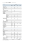
4.1 SEMI-AUTOMATIC MODELS . . . . . . . . . . . . . . . . . . . . . . . . . . . . . . . . . . . . . . . . pag. 24
4.2 AUTOMATIC MODELS . . . . . . . . . . . . . . . . . . . . . . . . . . . . . . . . . . . . . . . . . . . . . pag. 24
7.1 Connection to gas supply . . . . . . . . . . . . . . . . . . . . . . . . . . . . . . . . . . . . . . . . . . pag.
7.2 Venting the combustion fumes . . . . . . . . . . . . . . . . . . . . . . . . . . . . . . . . . . . . . . pag.
7.3 Ignition . . . . . . . . . . . . . . . . . . . . . . . . . . . . . . . . . . . . . . . . . . . . . . . . . . . . . . . . . pag.
7.4 Changing the calibration . . . . . . . . . . . . . . . . . . . . . . . . . . . . . . . . . . . . . . . . . . . pag.
8.
9.
10.
11.
Information for users in the European community . . . . . . . . . . . . . . pag.
Guarantee . . . . . . . . . . . . . . . . . . . . . . . . . . . . . . . . . . . . . . . . . . . . . . . . . . . . . . pag.
Declaration of conformity. . . . . . . . . . . . . . . . . . . . . . . . . . . . . . . . . . . . . . pag.
Problem solving . . . . . . . . . . . . . . . . . . . . . . . . . . . . . . . . . . . . . . . . . . . . . . . pag.
Manual Code: 7770.003
Revision 04/09
20
30
30
31
31
31
32
33
33
34
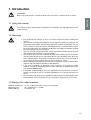
1. Introduction
ENGLISH
ATTENTION
#FGPSFVTJOHUIFNBDIJOFDBSFGVMMZSFBEBMMPGUIFJOTUSVDUJPOTDPOUBJOFEJOUIJTNBDIJOF
1.1 Using the manual
This manual contains all information required for the installation, use and maintenance of the
coffee machine.
1.2 Warnings
t %POPUPQFSBUFUIFNBDIJOFPSDBSSZPVUSPVUJOFNBJOUFOBODFCFGPSFSFBEJOHUIJT
manual.
t 5IJTNBDIJOFJTEFTJHOFEBOECVJMUGPSTFSWJOHFTQSFTTPDPGGFFIPUXBUFSGPSUIF
QSFQBSBUJPOPGCFWFSBHFTBOEJOGVTJPOT
BOETUFBNVTFEUPIFBUMJRVJET
5IFVTF
PGUIFNBDIJOFGPSBOZPUIFSUIBOJUTJOUFOEFEQVSQPTFTJTDPOTJEFSFEUPCFJNQSPQFSBOEVOBVUIPSJ[FE5IFNBOVGBDUVSFSEFDMJOFTBOZMJBCJMJUZGPSEBNBHFSFTVMUJOH
from the improper use of the machine.
t 5IFVTFSNVTUCFBSFTQPOTJCMFBEVMUXIPJTFYQFDUFEUPDPNQMZXJUIMPDBMTBGFUZ
rules and accepted common sense procedures.
t 5IFNBDIJOFNVTUOFWFSCFVTFEXJUIUIFGJYFEBOEPSNPCJMFHVBSETSFNPWFEPS
XJUIUIFTBGFUZEFWJDFTDVUPGG5IFTBGFUZEFWJDFTNVTUBCTPMVUFMZOFWFSCFSFNPWFEPSUBNQFSFEXJUI5IFQBOFMTDPWFSJOHUIFNBDIJOFNVTUOPUCFSFNPWFEBT
UIFNBDIJOFDPOUBJOTMJWFQBSUTUIFSFJTUIFSJTLPGFMFDUSJDTIPDL
t 4USJDUDPNQMJBODFXJUIUIFSPVUJOFNBJOUFOBODFJOTUSVDUJPOTPGUIJTNBOVBMJTSFRVJred for a safe and efficient operation of the appliance.
t *OUIFFWFOUPGQSPCMFNTPSCSFBLBHFPGBOZDPNQPOFOUPGUIFFTQSFTTPDPGGFF
NBDIJOFDPOUBDUBOBVUIPSJ[FETFSWJDFDFOUSFBOEJOTJTUPOPSJHJOBMTQBSFQBSUT
GSPN-"4"/."3$041"
t *GUIFQPXFSDPSEJTEBNBHFEJUNVTUCFSFQMBDFECZUIFNBOVGBDUVSFSUIFNBOVGBDUVSFSTUFDIOJDBMTFSWJDFPSBTJNJMBSMZRVBMJGJFEQFSTPOTPBTUPQSFWFOUBOZTPSU
PGSJTL
t 5IFVTFSNVTUOFWFSQFSGPSNBOZPQFSBUJPOGPSXIJDIIFTIFJTVOBVUIPSJ[FEPSMBDLT
USBJOJOH$POUBDUUIFNBOVGBDUVSFSGPSBOZJOGPSNBUJPOTQBSFQBSUTPSBDDFTTPSJFT
1.3 Starting the coffee machine
Ambient temperature:
Water pressure:
Water hardness:
5 ÷ 45° C (drain the water system in case of frost)
80 ÷ 800 kPa (0.8 ÷ 8.0 bar)
less than 5° fH
21
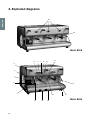
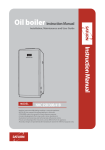
2. Exploded diagrams
ENGLISH
19
20
Mod. 85-S
6
7
8
9
11
10
5
4
3
2
12
1
15
18
22
17
16
13
14
Mod. 85-E
ENGLISH
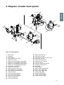
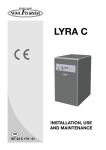
3. Diagram of water feed system
Key to illustrations:
1
2
3
4
5
6
7
8
9
10
11
12
13
14
15
16
17
18
19
20
Main switch
Pilot light
Steam spout
Cup warmer on/off switch
Steam valve lever
Button for serving single strong coffee
Button for serving single weak coffee
Button for serving double strong coffee
Button for serving double weak coffee
Continuous serving button
Hot water valve lever
Espresso coffee serving unit
Filter holding cup with handle
Manual boiler water filling lever
Hot water spout
Gas burner ignition button
Gas burner safety button
Two-scale pressure gauge
Coffee serving button
Visual level indicator
21
22
23
24
25
26
27
28
29
30
31
32
33
34
35
36
37
38
Boiler water drain tap
Automatic level tap
Push button valve with check valve
Automatic level tap
Check and safety valve
Automatic level solenoid
Pressure switch
Pressure switch setting screw
Grounds collecting tray
Drain pipe
Water softener
Water softener feeding pipe
Mains water supply tap
Mains water supply pipe
Pump feeding pipe
Machine feeding pipe
Pump (external model)
Pump (internal model)
23
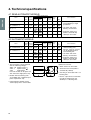
4. Technical specifications
4.1 SEMI-AUTOMATIC MODELS
ENGLISH
MODEL
POWER CONSUMTPION (W)
BOILER
NO. OF
POWER CONNECTION
CUP
BREWING CAPACITY
PUMP
WARMER
UNITS IN LITRES SINGLE PH. TRI-PH.
(Optional)
WEIGHT
(KG)
DIMENS.
A
(MM)
SPECIAL FEATURES
85 - PRACTICAL - S
1
4,9
1750
–
300
–
39
380
85 - SPRINT - S
2
4,9
3000
4500
275
–
56
626
r $PGGFFCSFXJOHJTTUBSUFE
and stopped by a single
pushbutton.
85 - S - 2
2
12
300
100
60
720
r )PUXBUFSBOETUFBN
delivery on all models.
85 - S - 3
3
19
300
125
74
960
85 - S - 4
4
25
300
150
85
1200
WEIGHT
(KG)
DIMENS.
A
(mm)
3500 3500
4500 4500
5500 5500
7000 7000
7000 7000
9000
r "VUPNBUJDXBUFSMFWFM
(boiler is automatically
refilled) on all models.
4.2 AUTOMATIC MODELS
MODEL
POWER CONSUMTPION (W)
BOILER
NO. OF
POWER CONNECTION
CUP
BREWING CAPACITY
PUMP
WARMER
UNITS IN LITRES SINGLE PH. TRI-PH.
(Optional)
SPECIAL FEATURES
r &MFDUSPOJDBMMZDPOUSPMMFE
coffee brewing: four
different automatic portions
can be programmed on
each brewing unit.
85 - PRACTICAL - E
1
4,9
1750
–
300
–
39
380
85 - SPRINT - E
2
4,9
3000
4500
275
–
56
626
85 - E - 2
2
12
300
100
60
720
r )PUXBUFSBOETUFBN
delivery on all models.
85 - E - 3
3
19
300
125
74
960
85 - E - 4
4
25
300
150
85
1200
r "VUPNBUJDXBUFSMFWFM
(boiler is automatically
refilled) on all models.
r 5IFTFNBDIJOFTDBOCFQPXFSFE
with the following voltages:
400V - 3N tri-phase (wire ()
230V - 3
tri-phase (wire )
230V
single-phase
Practical models can be powe red
with 110/230 V single-phase only.
r .PEFMTXJUIGPVSCSFXJOHVOJUT
are available with 3-Triphase input
power requirement only.
r 1VNQCVJMUJOUP413*/5NPEFM
external pump in the other models.
24
3500 3500
4500 4500
5500 5500
7000 7000
7000 7000
9000
Optional accessories
r 8BUFSTPGUFOFSPOBMMNPEFMT
r "VUPNBUJDXBUFSMFWFMCPJMFSJT
automatically refilled).
r (BTGJSJOHPOBMMNPEFMTXJUI
brewing units.
r &MFDUSJDDVQXBSNFSPOBMMNPEFMT
(except for PRACTICAL and
SPRINT) 2-3-4 brewing units.
t 5IFJOTUBMMBUJPONVTUCFDBSSJFEPVUCZBVUIPSJ[FE-B4BO.BSDPUFDIOJDBMQFSTPOOFM
t 5IFDPGGFFNBDIJOFJTEFMJWFSFEJOBTVJUBCMFDBSECPBSEBOETUZSPGPBNQBDLJOH
5IFQBDLJOHDPOUBJOTUIFNBDIJOFBOEJUTBDDFTTPSJFTUIFVTFSNBOVBMBOEUIFDPOGPSNJUZEFDMBSBUJPO
"GUFSPQFOJOHUIFQBDLJOHDIFDLUIFQSPQFSDPOEJUJPOPGUIFDPGGFFNBDIJOFBOEJUT
DPNQPOFOUT*ODBTFPGEPVCUEPOPUVTFUIFBQQMJBODFBOEDPOUBDU-B4BO.BSDP
4Q" 5IF QBDLJOH NVTU CF EJTQPTFE PG BU UIF QSPQFS XBTUF DPMMFDUJOH DFOUSFT JO
DPNQMJBODFXJUIMPDBMMBXT%POPUEJTDBSEJOUIFFOWJSPONFOU5IFQBDLJOHFMFNFOUT
DBSUPOTUZSPGPBNOZMPOTUBQMFTFUD
DBOCFBTPVSDFPGIB[BSET,FFQPVUPGSFBDI
of children.
t 5IF NBDIJOF TIPVME CF QMBDFE PO B QFSGFDUMZ IPSJ[POUBM QMBOF TVGGJDJFOUMZ TUVSEZ UP
TVQQPSUUIFXFJHIUPGUIFNBDIJOFXJUIBTVGGJDJFOUDMFBSBODFBSPVOEJUUPEJTTJQBUFUIF
heat generated during its operation.
5.1 Equipment in machine kit
The machine packing contains the equipment kit, which includes the following items:
- filter cups with filter restraint ring
- filters for filter cups (single and double doses)
- blind filter for filter cup
- spouts for filter cups (single and double doses)
- press for ground coffee
- braided 900 mm stainless-steel tube for water connection (water supply - water softener)
- rubber drain hose with steel coil for water drain
- 3/8" nipples for hose connection to water supply tube
- cleaning brush for serving units
- pump suction filter (on request)
- braided 600 mm stainless-steel tube for water connection (pump inflow - water softener) optional only for external pump
- braided 1600 mm stainless-steel tube for water connection (pump outflow - coffee machine) optional only for external pump;
5.2 Prearrangement of water supply
FEEDING LINE
Bring the water feeding tube (of at least 3/8" diameter) up to the machine and install an on-off valve (preferably of 3/8" ball type) that allows a rapid opening and closing operation.
DRAIN LINE
Provide an inspectable drainage pit on the floor connected with the sink drainage line, suitable for receiving
the machine gravity drainage tube.
The drain tube must be positioned so that the water flows out freely, without possibility for the pipe to clog
up during the operation.
5.3 Water softener (optional)
The water softener for the mains water can be manual or automatic, depending on customer's request.
#FGPSFDPOOFDUJOHUIFXBUFSTPGUFOFSUPUIFDPGGFFNBDIJOFUIFSFTJOTDPOUBJOFEJOJUTIPVMECF
XBTIFEPGGBTEFTDSJCFEJOUIFVTFShTNBOVBMTVQQMJFEXJUIUIFBQQMJBODF
/PUF
5IFXBUFSTPGUFOFSJTDPOTJEFSFEBOFTTFOUJBMEFWJDFUPHVBSBOUFFBQSPQFSPQFSBUJPOPGUIFFTQSFTTPDPGGFF
NBDIJOF"XBUFSTPGUFOJOHTZTUFNTIPVMECFQSPWJEFEJOPSEFSUPHVBSBOUFFUIFFGGJDJFODZQFSGPSNBODFBOE
duration of the components in the machine.
25
ENGLISH
5. Installation
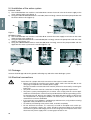
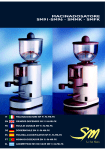
5.4 Installation of the water system
ENGLISH
INTERNAL PUMP
1) Use the braided 900 mm stainless-steel tube 32 to connect the on-off valve of the water supply to the
water softener inflow valve (figure 1).
2) Using the rubber-braided 35 stainless-steel tube (2500 mm long), connect the internal pump intake with
the water softener valve (figure 2).
32
35
Figure 1
Figure 2
EXTERNAL PUMP
1) Use the braided 900 mm stainless-steel tube 32 to connect the water supply on-off valve to the water
softener inflow valve 1 (figure 3).
2) Using the rubber-braided stainless-steel tube 35 (600 mm long), connect the pump intake with the water
softener valve (figures 3-4).
3) Using the rubber-braided stainless-steel tube 36 (1600 mm long), connect the pump outflow with the
nipple 5 of the water system on the machine (figures 4-5).
36
35
Figure 3
Figure 4
35
Figure 5
36
5.5 Drainage
Connect the drainage tube to the grounds collecting tray and to the water drainage system.
5.6 Electrical connections
26
*OTUSVDUJPOTGPSBQSPQFSFMFDUSJDBMDPOOFDUJPOPGUIFFTQSFTTPDPGGFFNBDIJOF
t #FGPSFDPOOFDUJOHUIFNBDIJOFUPUIFQPXFSTVQQMZNBLFTVSFUIBUUIFEBUBPOUIF
SBUJOHUBHDPSSFTQPOEUPUIFBWBJMBCMFQPXFSTVQQMZ
5IFUBHJTMPDBUFEPOUIFMFGUTJEFPGUIFNBDIJOFBOEDBOCFBDDFTTFECZSFNPWJOHUIF
MPXFSUSBZ
t 5IFQPXFSDPOOFDUJPONVTUCFDBSSJFEPVUBDDPSEJOHUPBQQMJDBCMFSFRVJSFNFOUT
t 5IFQPXFSTZTUFNQSFBSSBOHFECZUIFDVTUPNFSNVTUDPNQMZXJUIUIFDVSSFOUBQQMJDBCMFMBXTBOEUIFQPXFSTPDLFUNVTUCFQSPWJEFEXJUIBOFGGJDJFOUHSPVOEJOHTZTUFN
-B4BO.BSDP4Q"EFDMJOFTBOZMJBCJMJUZJGUIFBQQMJDBCMFQSFTDSJQUJPOTPGUIFMBXBSF
OPUDPNQMJFEXJUI"OJNQSPQFSJOTUBMMBUJPODBODBVTFJOKVSZPSEBNBHFGPSXIJDIUIF
manufacturer cannot be held liable.
t *GJUJTOFDFTTBSZUPVTFBEBQUFSTNVMUJQMFQMVHTBOEFYUFOTJPOTPOMZQSPEVDUTNFFUJOH
BQQMJDBCMFTBGFUZTUBOEBSETNVTUCFVTFE
t 5PBWPJEBOZPWFSIFBUJOHPGUIFQPXFSDBCMFVOXJOEJUDPNQMFUFMZ
t 'PS UIF FMFDUSJDBM DPOOFDUJPO JU JT OFDFTTBSZ UP JOTUBMM BO PNOJQPMBS NBJO TXJUDI VQTUSFBN PG UIF QPXFS TVQQMZ UIJT TXJUDI TIPVME CF SBUFE BDDPSEJOH UP UIF FMFDUSJDBM
DIBSBDUFSJTUJDTQPXFSBOEWPMUBHF
TIPXOPOUIFSBUJOHUBH5IFPNOJQPMBSTXJUDINVTU
EJTDPOOFDUUIFQPXFSTVQQMZXJUIBDPOUBDUHBQPGBUMFBTUNN
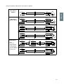
Connect the power cable to the main switch as follows:
110V/230V SINGLE PHASE
N
L
1 HEATING ELEMENT
BLUE
BLUE
BROWN
BROWN
YEL/GREEN
YEL/GREEN
230V SINGLE PHASE
ONLY FOR 85
COMPACT MODELS
N
L
2 HEATING ELEMENTS
BLUE
BLACK
BLACK
BLACK
BLACK
BROWN
BROWN
BLUE
YEL/GREEN
YEL/GREEN
400V-3N THREE PHASE
N
L3
L2
L1
3 HEATING ELEMENTS
BLUE
BLUE
BLACK
BLACK
BLACK
BROWN
BROWN
BLACK
YEL/GREEN
YEL/GREEN
230V-3 THREE PHASE
L3
L2
L1
ENGLISH
ONLY FOR 85 1
MODELS
3 HEATING ELEMENTS
BLUE
BLUE
BLACK
BLACK
BLACK
BROWN
BROWN
YEL/GREEN
BLACK
YEL/GREEN
OTHER MODELS
NOTES:
* The power
absorbed by the
heating elements
can be reduced
to 2/3 by eliminating one of the two
BLACK cables.
230V SINGLE PHASE
N
BLUE
BLACK
BLACK
L
BROWN
YEL/GREEN
230V-3 THREE PHASE
L3
L2
L1
*
400V-3N THREE PHASE
N
L3
L2
L1
3 HEATING ELEMENTS
BLUE
BLUE
BLACK
BLACK
BLACK
BLACK
BROWN
BROWN
YEL/GREEN
YEL/GREEN
3 HEATING ELEMENTS
BLUE
BLUE
BLACK
BLACK
BLACK
BROWN
BROWN
YEL/GREEN
BLACK
YEL/GREEN
27
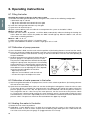
6. Operating instructions
ENGLISH
6.1 Filling the boiler
Checking the position of the taps in the water system
a) Remove the coffee ground collection tray with grille. Now, check for the following configuration:
r#PJMFSESBJOUBQDMPTFE
r5BQPOUIFBVUPNBUJDMFWFMDPOUSPMWBMWFPQFO
r5BQPOUIFBVUPNBUJDMFWFMDPOUSPMWBMWFPQFO
b) Install the coffee ground collection tray with grille
c) Open the main water fill tap 33
d) Open a steam delivery lever 5 to allow air to escape from the system as the boiler is filled.
Mod. 85 - Practical - S/E
e) Move the main switch 1 to position 1 to fill the boiler automatically without activating the heating elements. When the water reaches the probe, the “MAX” led will light up. When the boiler is full, turn the
main switch to working position 2.
Mod. 85 - S/E - 2 - 3 - 4
f) Make sure that the main switch 1 is in position “zero”.
g) Press and hold down the button 14 until the sight glass 20 is 3/4 full.
6.2 Calibration of pump pressure
a) Once the boiler is filled, turn the main switch to position 2 (the heating elements start to heat the water).
b) Press the continuous-feeding push button 19 for the manual serving machines or the push button 10 for
the electronic machines with automatic serving, so that the water flows out of the unit corresponding to
the pressed button.
c) Read the water pressure value on the lower part of the
pressure gauge 18. The optimum pressure is 9 bar.
PUMP SCREW
The pressure is adjusted to the desired value by operating on the pump screw: the pressure is increased by
turning clockwise; it is decreased by turning counterclockwise. As shown in the following figure, there are
three different cases for adjusting this screw, depending on the pump installed on the machine:
- adjust only the screw
- adjust the screw and lock it with the lock nut
- unscrew the cap nut and adjust the screw.
6.3 Calibration of water pressure in the boiler
a) After having filled the boiler to the proper level, turn the main switch to position 2 (the heating elements
will start to heat the water).
b) Open the lever-controlled steam valve 5 to vent the air during the heating phase. Close the valve as soon
as the steam phase is reached. The steam pressure in the boiler can be read on the upper scale of the
pressure gauge 18 from 0 to 3 bar. The pressure rises to the calibration value of the pressure switch 27
in the range from 0.9 to 1.1 bar. To vary the steam pressure, turn the screw 28 on the pressure switch
27. The pressure is decreased by turning the screw clockwise and it is increased by turning the screw
counterclockwise. The screw is adjusted by means of a screwdriver inserted into the hole on the lid of the
pressure switch. The pressure switch can be reached from the upper tray and grill.
6.4 Heating the water in the boiler
a) Rotate the main switch to position 2.
b) Hold down a steam delivery lever 5 to allow air to escape from the system as the machine heats up.
Release the lever as soon as steam escapes from the delivery pipe. Boiler pressure is indicated on the
0-to-3-bar scale on the pressure gauge 18 (suggested value: 0.9-1.2 bar).
28
6.5 Electric cup warmer (Optional)
The on/off button 4 is used to heat the cup holding shelf; it can be switched on and off at will.
This function is used to deliver steam from the boiler to heat liquids, or to foam milk for cappuccinos. Lower
or raise the lever 5 to obtain the maximum flow of steam. Move the lever sideways to the left of right to obtain
a reduced steam flow.
6.7 Hot water delivery
The lever-operated tap 11 is used to deliver hot water from the boiler for making tea, camomile herb tea, etc.
This lever operates in the same way as the steam delivery lever.
6.8 Preparation of ground coffee
Make sure that the filter with the desired capacity has been installed in the filter holder. After the coffee has
been loaded and pressed into the filter, the coffee level in the filter must just touch the spray head on the
brewing unit. To check for correct coffee level, install the full filter holder onto the brewing unit and then remove the holder. Now, look at the surface of the coffee: if the level is correct, the coffee will contain the imprint
of the central mounting screw on the spray head of the brewing unit.
6.9 Brewing coffee
Semiautomatic models: 85 - S
Once the filter holder has been installed onto the machine, simply press the switch 19 to actuate the pump
and solenoid valve. When the coffee in the cup has reached the desired level, move the switch back to its
original position to terminate brewing.
Automatic models: 85 - E
Once the filter holder has been installed onto the machine, press one of the five brewing buttons. The first two
buttons 6 and 7 are used to select the two pre-programmed single portions of coffee. The second two buttons
8 and 9 are used to select the two pre-programmed double portions of coffee. The fifth button 10 immediately
shuts down brewing if pressed during a coffee brewing cycle. Button 10 can also be used to brew the desired
quantity of coffee manually: press this button to start brewing, and presse the button a second time to stop
brewing when the desired quantity of coffee has been obtained.
6.10 Draining the boiler
If the boiler must be emptied, shut off the power to the machine by moving the main switch 1 to the “zero”
position. On gas-fired machines, extinguish the flame by closing the gas feed valve. Open the drain tap 21
until the boiler has been completely drained.
Important: be sure to close the tap before refilling the boiler.
6.11 Automatic operation - programming the coffee brewing cycles
Automatic models: 85 - E
A. Entering the programming mode
Set the main switch 1 on the machine to position “zero” (machine switched off).
Hold down the fifth button 10 on the first brewing unit. Now, rotate the main switch 1 to position 1 (machine
switched on). After a few seconds, release the button 10. The indicator led for the button will now begin to
flash, as will the same led on all the other brewing units. The machine is now ready for programming.
B. Programming
To program the four portions on brewing unit I, proceed as follows: place the single-portion filter into the
single-portion filter holder. Use the coffee dispenser to dispense a single portion of coffee into the filter.
Mount the filter holder onto brewing unit I.
Place an espresso cup under the spout on the filter holder.
Press the first button 6 whose portion is to be programmed. When the coffee in the cup reaches the
desired level, press the fifth button 10 to stop brewing.
Follow the same procedure to program the other portions on each group. Once the four portions on brewing unit I have been programmed as desired, the relative data can be transferred to the other brewing
units by pressing the fifth button 10 on each unit. When each button 10 is pressed, the indicator led for
the button will stop flashing and remain steadily lit. This shows that the data on brewing unit I has been
transferred successfully.
29
ENGLISH
6.6 Steam delivery
C. &YJUJOHGSPNUIFQSPHSBNNJOHNPEF
After you have finished programming the machine, press the button 10 (with flashing led) on brewing unit I
and all the leds will turn off. The programmed quantity of coffee will now be delivered when an automatic
brewing button is pressed.
ENGLISH
6.12 Important information on daily maintenance
To keep your espresso machine in top operating condition and obtain maximum performance, the followint
cleaning operations must be performed on the brewing units at the end of the work day:
a) Install the blank filter (without holes) into the filter holder. This filter is provided with the machine.
b) Install the filter holder with blank filter onto the brewing unit to be cleaned but do not tighten the holder,
thus allowing water to overflow at the sides. Push the continuous brewing button and let the water run
for about a minute. This will clean the spray head and the water delivery pipe in the unit.
c) Tighten the filter holder onto the brewing unit so that water can no longer overflow at the sides. Manually
run the unit once again for around 5 seconds, and then shut the unit down. Repeat this operation 5 or 6
times to clean the solenoid valve and the drain pipe on the unit.
/PUF To clean the brewing units more thoroughly, the blank filter can be filled with one of the special detergents that are available on the market.
6.13 Alarms
A flashing Led on the first button of pushbutton array indicates a malfunction on the flow meter.
A flashing Led on the second button of all the pushbutton arrays indicates a malfunction on the automatic
boiler refill system (jammed solenoid valve, insufficient water from the main water system, etc.). After 1’30”,
the pump motor will shut down.
Note: If the machine shuts down as described above, call your local service technician.
t %POPUVTFXBUFSTQSBZTTUFBNPSTJNJMBSDMFBOJOHNFUIPET#FGPSFDMFBOJOHPSNBJOUFOBODFPQFSBUJPOT%*4$0//&$55)&$"#-&*'1044*#-&05)&38*4&4)650''
5)&0./*10-"3."45&348*5$)*/45"--&%")&"%0'5)&."$)*/&
t *G QPXFS DBCMF JT EBNBHFE JU NVTU CF SFQMBDFE XJUI UIF TQFDJBMMZ QSFQBSFE PSJHJOBM
FRVJQNFOUSFQMBDFNFOUQBSUXIJDIDPOGPSNTUPTBGFUZSFHVMBUJPOT
t 4QFDJBMNBJOUFOBODFQBSUTSFQMBDFNFOUMPOHUFSNTPVUEPXOBOEEJTQMBOUJOHPQFSBtions must be performed bZ-"4"/."3$0TFSWJDFQFSTPOOFM
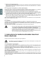
7. Instructions for Authorized Installer Gas fired
Boiler (Optional)
Read the instructions before installing and using the appliance.
5IJTBQQMJBODFDBOPOMZCFJOTUBMMFEBOEVTFEJOQFSNBOFOUMZWFOUJMBUFEQMBDFTBDDPSEJOHUP6/*
$*(BOE6/*$*(4UBOEBSET
7.1 Connection to gas supply
Position the appliance as described in the Use and Maintenance Manual, remove the control panel as described in the same handbook, and connect the appliance to the gas supply mains, or LPG bottle (G30/G31),
using rigid metal pipes or flexible metal tubes according to UNI-CIG 9891 Standards.
Check that the appliance is prearranged for the type of gas actually being used; the corresponding setting is
shown on the settings tag.
If the appliance is prearranged for a different type of gas, change the arrangement as described in the paragraph “Changing the calibration”.
The gas infeed, consisting of an on-off valve (51), includes a G 1/8” threaded connection (thread is not gastight) according to ISO 228-1 Standard.
If using rigid metal pipes for connection to the gas supply, place an appropriate fitting between the valve and
the rigid metal pipe, which should be provided with a G 1/8” female thread (thread is not gas-tight) according
to ISO 228-1 Standard.
30
If using flexible metal tubes for connection to the gas supply, interpose an appropriate G 1/2” female nipple
(gas-tight thread) according to ISO 7-1 Standard and a G 1/2” male nipple (thread is not gas-tight) according
to ISO 228-1 Standard; interpose a suitable gas-tight gasket.
When the connection is completed, open the gas flow upstream of the appliance and, using a soapy solution
(never a free flame), check the perfect tightness of the connection.
In relation to the venting of the combustion fumes, the appliance is of Type A1: i.e., it draws in the air required
for combustion from the room and discharges the fumes in the same environment.
Place particular attention to the volume of the room where the appliance is to be installed: this should be at
least 12 m3.
If the room has a smaller volume, it will be necessary to install the appliance directly under a suction hood,
and also to provide a combustion air intake with a free-flow cross section of al least 100 cm2.
7.3 Ignition
Press and turn the gas valve knob (51) counterclockwise to the position of the flame symbol, as shown in Fig.
B. While holding the knob pressed, push a few times the burner ignition button, marked with the star symbol
(53) to ignite the burner (piezoelectric ignition).
When the flame is lit, check through the relative hole (54), while keeping the gas knob pressed for 5-10 seconds. After this period, if the flame does not remain lit, repeat the ignition operation again.
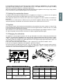
7.4 Changing the calibration
The appliance is prearranged to operate with the gas indicated in the relative settings tag attached to the
appliance. The information regarding the air setting, injector, rated and reduced heat flow are shown in Tables
1 and 2. The data that correspond with each model are indicated by the next-to-last character of the code for
the relative model. For example, the model code shown on the tag for the gas part characteristic 85-E-3-G
shows number 3 in the next-to-last digit.
In this case, refer to the data shown in Tables 1 and 2, respectively, in the column headed “3 Units”.
If you wish to change the calibration of the appliance, proceed as follows:
Unscrew the primary air adjusting ring nut (55 - Fig. C) to expose the nozzle (56). Using the relative wrench,
unscrew the nozzle (56) and replace it with the proper one indicated in Table 2, checking that the diameter
marked on the same nozzle corresponds to the right diameter.
1° GRUPPO
2
0
2° GRUPPO
1
1
53
51
54
Table 1 - Adjusting the primary air (Fig. C)
Gas
2 Units
3 Units
4 Units
GPL
(G30/G31)
L = 8 mm
L = 10 mm L = 12 mm
Nat. gas
(G20)
L = 4 mm
L = 4 mm
Table 2 - Nozzle diameters in 100/mm
Gas
2 Units
3 Units
4 Units
GPL
(G30/G31)
40
55
65
Nat. gas
(G20)
60X
81X
90X
Qn = Rated heat flow
Qn (kW)
0,75
1,45
1,9
Qnr = Reduced rated heat flow
Qnr (kW)
N.A.
1,0
1,3
L = 4 mm
31
ENGLISH
7.2 Venting the combustion fumes
ENGLISH
Screw on the new nozzle (56), and position the primary air adjusting ring nut (55 - Fig. C) according to the
indications of Table 1, using a gauge or equivalent instrument to set the distance “L”, and tighten the screw
provided to fasten the nozzle.
Turn the main switch (1) to position 1, so as to connect a single heating element (50% of the boiler’s electric
power for single-phase heating element with 2 elements and 1/3 of power for heating elements with 3 elements with three-phase connection), and ignite the burner as in the procedure described above. When the
water contained in the boiler reaches the preset temperature, the gas flow regulator will automatically decrease the flow to the value corresponding to the reduced rated heat flow.
At this point, turn the flow regulation screw (58) so as to have a steady flame licking the sensitive thermocouple element (52), and turn the screw (57) to obtain the maximum desired pressure value in the boiler.
After having verified the proper operation, replace the settings tag on the appliance with the one for the new
type of gas that is provided with the standard kit containing the newly installed gas nozzle.
Safety devices on appliance (manually reset).
The appliance is provided with two safety devices that shut off the gas flow if the flame accidentally goes out.
1 - Termocouple (52): The thermocouple operates on the valve (51), whose probe (52) must be licked by
the flame from the burner (50). If the probe is not enveloped by the flame, the gas flow will be automatically shut off.
2 - Thermostat (59): The thermostat, placed in contact with the boiler, operates on the valve (51); when the
thermostat sensor on the boiler reads 140˚C, the gas flow will be automatically shut off.
The burner can be re-ignited with the procedure described above only after the boiler body has cooled to
110˚C. Following the activation of one of the two safety devices, try re-igniting the burner with the procedure
already described.
*GUIFNBMGVODUJPOQFSTJTUTBOEUIFCVSOFSDPOTFRVFOUMZDPOUJOVFTUPHPPGGDPOUBDUUIFOFBSFTU
BVUIPSJ[FE4FSWJDFPVUMFUXIJDIXJMMQSPWJEFUPFMJNJOBUFUIFDBVTFPGUIFNBMGVODUJPO
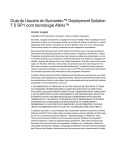
8. Information for users in the European community
Pursuant to European Directive 2002/96/EC on electrical waste (WEEE), users in the European community are advised of the following.
The symbol with the crossed-out dustbin on the appliance or its packaging indicates that at
the end of the product’s life cycle, it must be collected separately from other waste.
Suitable separate collection of the equipment for subsequent recycling, treatment and disposal contributes to preventing possible negative consequences for the environment and
health, and favours the recycling of materials that the unit is made of.
In accordance with European Directive 2002/96/EC, abusive disposal of the product by the user will result in
application of penalties as set forth by local law.
32
The warranty becomes void if:
r 5IFJOTUSVDUJPOTJOUIJTNBOVBMBSFOPUDPNQMJFEXJUI
r 5IFTDIFEVMFENBJOUFOBODFBOESFQBJSTBSFDBSSJFEPVUCZVOBVUIPSJ[FEQFSTPOOFM
r 5IFNBDIJOFJTVTFEGPSBOZPUIFSUIBOJUTJOUFOEFEQVSQPTFT
r 5IFPSJHJOBMQBSUTBSFSFQMBDFEXJUIQBSUTGSPNEJGGFSFOUNBOVGBDUVSFST
r 5IFXBSSBOUZEPFTOPUDPWFSEBNBHFDBVTFECZOFHMFDUVTFBOEJOTUBMMBUJPOOPUJODPNQMJBODFXJUIUIF
recommendations of this manual, improper operation, abuse, lightning and atmospheric phenomena,
overvoltage, overcurrent, or insufficient or irregular power supply.
10. Declaration of conformity
The manufacturer:
La San Marco S.p.A.
34072 Gradisca d’Isonzo (GO) Italy – Via Padre e Figlio Venuti, 10
phone (+39) 0481 967111 – fax (+39) 0481 960166 – http://www.lasanmarco.com
declares under its own responsibility that the espresso coffee machine described in this manual and identified by the data on the tag located on the machine, is compliant with directives 98/37/EC, 2006/95/EC,
89/336/EEC, Regulation (EC) No 1935/2004. For verification of compliance with said directives, the following
harmonized standards have been applied: EN 12100-1, EN 12100-2, EN 60335-1, EN 60335-2-75
Gradisca d’Isonzo, April 2009
Managing director
Mr Roberto Marri
33
ENGLISH
9. Guarantee
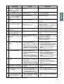
11. Problem solving
ENGLISH
PROBLEM
CAUSE
SOLUTION
1.
The boiler is full of water
r0OF PG UIF PVUGMPX MJOFT GSPN r$IFDLUIFBVUPMFWFMDJSDVJUUIFNBOand the water flows out of
the boiler or from a circuit of ual charging button, and the boiler
the safety valve.
heat exchangers.
the unit has a leak.
r3FQMBDF XPSO PS EBNBHFE QBSUT UP
eliminate the leak.
2.
The safety valve trips in
and vents the steam.
3.
The machine was started r5IFFMFDUSJDIFBUJOHFMFNFOUJT r$IFDL JG UIF IFBUJOH FMFNFOU JT DPOproperly but the water in the defective or is not connected.
nected to the power supply.
r$IFDL JG UIF IFBUJOH FMFNFOU TBGFUZ
boiler does not warm up.
thermostat has tripped in and check
its proper operation.
r*O UIF NBDIJOFT XJUI FMFDUSPOJD UFNperature control, check the proper
operation of the electronic control
unit, the triac, the level probe, and the
electrical wiring.
4.
There is no water flowing r$PGGFF HSPVOE UPP GJOF PS r"EKVTU UIF HSJOEJOH DPBSTFOFTT BOE
from a serving unit.
excessive quantity for type of or the quantity of ground coffee.
r$IFDL UIBU UIF JOKFDUPS UIF VQQFS
filter used.
circulation tube, the spray nozzle
r$MPHHFEXBUFSDJSDVJU
r%FGFDUJWFTPMFOPJE
and the solenoid of the unit are not
clogged.
r*OUIFNBDIJOFTXJUIFMFDUSPOJDNFUFSing, check the displacement meter
and its valves.
r$IFDL UIF TPMFOPJE PG UIF VOJU JUT
wiring and the fuse in the electronic
control unit.
5.
The programmed servings r"COPSNBM PQFSBUJPO PG UIF r1SPHSBNUIFTFSWJOHRVBOUJUJFTTFQBof espresso coffee are not electronic control unit or of the rately on each serving unit. If the
constant or vary on the dif- displacement counters.
problem persists, replace the disferent units.
r-FBLGSPNTFSWJOHVOJUTPMFOPJE placement meter of the serving unit
valve.
affected.
r3FQMBDF UIF TPMFOPJE WBMWF PG UIF
serving unit.
6.
It is not possible to pro- rAbnormal operation or defective r$IFDL UIF DPOUSPM VOJUEJTQMBDFNFOU
gram the serving quantities displacement meter of unit 1.
meters electrical wiring.
on unit 1 and to copy them
r3FQMBDFUIFEJTQMBDFNFOUNFUFS
on the other units.
7.
Displacement meters alarm. r%JTQMBDFNFOU NFUFST KBNNFE r3FQMBDFUIFEJTQMBDFNFOUNFUFS
or defective.
r$IFDLUIFXJSJOHBOEJUTDPOOFDUJPOT
r%FGFDUJWFXJSJOH
the control unit and the fuses.
8.
Autolevel alarm.
9.
The machine is switched on r5IFFMFDUSJDXJSJOHPGUIFFMFD- rCheck the electrical wiring, the elec(the main switch is in posi- tronic control unit is defective.
tronic control unit and its compotion 1 or 2 and the signal r5IF FMFDUSPOJD DPOUSPM VOJU JT nents.
light is lit) but the electronic defective.
r3FQMBDFUIFFMFDUSPOJDDPOUSPMVOJU
control is out of order.
34
rMalfunction of electrical system rCheck the wiring that feeds the heat(the electrical heating element ing element and the pressure switch.
r*O UIF NBDIJOFT XJUI FMFDUSPOJD UFNis always connected).
r1SFTTVSF JODSFBTF JO UIF CPJMFS perature control, check the proper
(the safety valve trips in at 1.9- operation of the electronic control
unit, the triac, the level probe, and the
2.5 bar).
electrical wiring.
r-BDL PG XBUFS JO UIF BVUPMFWFM r$IFDL UIF IZESBVMJD DJSDVJU PG UIF
autolevel.
circuit.
r.BJO XBUFS TVQQMZ WBMWF r$IFDLJGUIFPOPGGWBMWFPOUIFXBUFS
closed.
supply is open.
r3FQMBDFUIFBVUPMFWFMTPMFOPJE
r'BVMUZBVUPMFWFMTPMFOPJE
PROBLEM
CAUSE
SOLUTION
10. The machine feeds water r4PMFOPJEBOEPSQVNQGFEDPO- rShort-circuited control unit relay.
r3FQMBDFUIFFMFDUSPOJDDPOUSPMVOJU
from one serving unit tinuously.
although the serving has
not been selected.
ENGLISH
11. 85 S models: one unit r&MFDUSJD DJSDVJU PG VOJU JNQSPQ- r$IFDL UIF DPOOFDUJPO BOE DPSSFDU JU
erly connected.
(see wiring diagram).
serves water continuously.
12. The steamer discharges r8PSOHBTLFUPOUBQ
only small quantities of
steam or water droplets.
r3FQMBDFUIFHBTLFU
13. Small drops flow out of the r8PSOHBTLFUPOUBQ
r-FBLGSPNTPMFOPJE
water tap.
r3FQMBDFUIFHBTLFU
r$IFDL UIF TPMFOPJE BOE JG OFDFTTBSZ
replace it.
14. The unit emits a whistle r'BVMUZ PQFSBUJPO PG FYQBOTJPO r$IFDL UIF FYQBOTJPO WBMWF BOE JG
valve.
necessary replace it. Calibrate the
after serving the coffee.
r)JHIQVNQQSFTTVSF
valve at 12 bar.
r$IFDLUIFQVNQPQFSBUJOHQSFTTVSF
Calibrate the pump at 9 bar.
15. The filter cup comes off the r8PSO HBTLFU VOEFS UIF GJMUFS r3FQMBDFUIFHBTLFU
rClean the serving unit and the filter cup.
cup.
serving unit.
16. When coffee is being served, r8PSO HBTLFU VOEFS UIF GJMUFS r3FQMBDFUIFHBTLFU
r$MFBO UIF TFSWJOH VOJU BOE UIF GJMUFS
some of it drips out of the cup.
cup.
edge of the filter cup.
r$IFDLUIFVOJUTPMFOPJE
17. Water leaking from the rMalfunctioning unit solenoid.
drain of the serving unit r8BUFSMFBLJOHGSPNVOJUDPPMJOH r$IFDL UIF QMVOHFS PO UIF TPMFOPJE
system.
and clean the solenoid.
solenoid.
r3FQMBDFUIFTPMFOPJE
r$IFDL UIF DPPMJOH UVCF BOE UIF TFBM
rings inside the unit.
18. Light cream (the coffee a. Coarse grinding.
flows out of the spout b. Low pressing pressure.
rapidly).
c. Small quantity of ground coffee.
d. Water temperature below 90°C.
e. Pump pressure above 9 bar.
f. Sprinkler filter on unit clogged.
g. Filter holes widened (filter cup).
a.
b.
c.
d.
e.
f.
19. Dark cream (the coffee a. Fine grinding.
drips out of the spout).
b. High pressing pressure.
c. Large quantity of ground coffee.
d. High percolation water temperature.
e. Pump pressure below 9 bar.
f. Sprinkler filter on unit clogged.
g. Filter holes clogged (filter cup).
a.
b.
c.
d.
e.
f.
20. Presence of grounds in cof- a. Coffee ground too fine.
b. Worn grinders in grinder-disfee cup.
penser unit.
c. Pump pressure above 9 bar.
d. Sprinkler filter on unit clogged.
e. Filter holes widened (filter cup).
a.
b.
c.
d.
21. Coffee with too little cream r 4QSJOLMFS
clogged.
in cup (spurts out of spout).
GJMUFS
PO
Finer grinding.
Increase the pressure.
Increase the quantity of ground coffee.
Increase the pressure in the boiler.
Decrease the pump pressure.
Check and clean with blind filter or
replace.
g. Check and replace the filter.
Coarser grinding.
Reduce the pressure.
Decrease the quantity of ground coffee.
Decrease the boiler pressure.
Increase the pump pressure.
Check and clean with blind filter or
replace.
g. Check and replace the filter.
Coarser grinding.
Replace the grinders.
Decrease the pump pressure.
Check and clean with blind filter or
replace.
e. Check and replace filter.
VOJU r $IFDL BOE DMFBO XJUI CMJOE GJMUFS PS
replace.
22. The cream in the cup is too r $PGGFFFYUSBDUJPOUBLFTBMPOH r $MFBOPSSFQMBDFUIFGJMUFS
time due to clogged filter.
thin (it disappears after a
r $MFBOPSSFQMBDFUIFTQSJOLMFSGJMUFS
r $PGGFFFYUSBDUJPOUPPGBTUEVF r -PXFSUIFUFNQFSBUVSFJOUIFCPJMFS
few seconds).
to clogged sprinkler filter.
r 8BUFSUFNQFSBUVSFUPPIJHI
23. Presence of depressions in r 4QSJOLMFSGJMUFSQBSUMZDMPHHFE r $MFBOPSSFQMBDFUIFTQSJOLMFSGJMUFS
the coffee grounds (looking r -PXBNPVOUPGHSPVOEDPGGFF r "EKVTU UIF BNPVOU PG HSPVOE DPGinside the filter cup).
for the fiter used.
fee.
/PUF*GJUJTOPUQPTTJCMFUPTPMWFUIFQSPCMFNBTEFTDSJCFEBCPWFPSJGPUIFSNBMGVODUJPOTEFWFMPQDPOUBDU
UIFBVUIPSJ[FE-B4BO.BSDPTFSWJDFDFOUSF
35
La San Marco S.p.A.
M`XGX[i\\=`^c`fM\elk`#('
*+'.)>iX[`jZX[Ë@jfeqf$>fi`q`X$@kXcp
K\c%"*0%'+/(%0-.(((=Xo"*0%'+/(%0-'(-_kkg1&&nnn%cXjXedXiZf%Zfd
<$dX`c1`e]f7cXjXedXiZf%Zfd