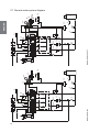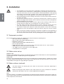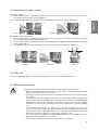
1
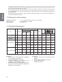
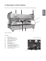
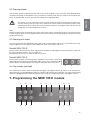
NEW 105 E
NEW 105 S
IT
USO E MANUTENZIONE
ES
MANUAL DE USO Y
MANTENIMIENTO
EN
USE AND MAINTENANCE
PT
MANUAL DE USO E
MANUTENÇÃO
FR
MANUEL D’INSTRUCTIONS
POUR L’EMPLOI
EL
!°Ã!"ƒ"¢"# #¢$°"ø¡ Ã$TM$TM
%&" TMÀ¡'$
DE
BEDIENUNGS- UND WARTUNGTSANLEITUNG
ENGLISH
USE AND MAINTENANCE
SERIES NEW 105
ENGLISH
Index
1.
Introduction
2.
Description of the machine . . . . . . . . . . . . . . . . . . . . . . . . . . . . . . . . . . . . pag. 27
2.1 General water system diagram . . . . . . . . . . . . . . . . . . . . . . . . . . . . . . . . . . . . . . pag. 28
2.2 Water system diagram key. . . . . . . . . . . . . . . . . . . . . . . . . . . . . . . . . . . . . . . . . . pag. 29
3.
Installation . . . . . . . . . . . . . . . . . . . . . . . . . . . . . . . . . . . . . . . . . . . . . . . . . . . . . . pag.
3.1 Equipment provided. . . . . . . . . . . . . . . . . . . . . . . . . . . . . . . . . . . . . . . . . . . . . . . pag.
3.2 Water mains set-up . . . . . . . . . . . . . . . . . . . . . . . . . . . . . . . . . . . . . . . . . . . . . . . pag.
3.3 Water softener (optional) . . . . . . . . . . . . . . . . . . . . . . . . . . . . . . . . . . . . . . . . . . . pag.
3.4 Installation of water system . . . . . . . . . . . . . . . . . . . . . . . . . . . . . . . . . . . . . . . . . pag.
3.5 Drain line . . . . . . . . . . . . . . . . . . . . . . . . . . . . . . . . . . . . . . . . . . . . . . . . . . . . . . . pag.
3.6 Electrical connection . . . . . . . . . . . . . . . . . . . . . . . . . . . . . . . . . . . . . . . . . . . . . . pag.
4.
Start-up . . . . . . . . . . . . . . . . . . . . . . . . . . . . . . . . . . . . . . . . . . . . . . . . . . . . . . . . . pag. 33
4.1 Charging the water in the boiler . . . . . . . . . . . . . . . . . . . . . . . . . . . . . . . . . . . . . . pag. 33
5.
Adjustments . . . . . . . . . . . . . . . . . . . . . . . . . . . . . . . . . . . . . . . . . . . . . . . . . . . . pag.
5.1 Adjustment of the boiler water level probe . . . . . . . . . . . . . . . . . . . . . . . . . . . . . pag.
5.2 Adjustment of pump serving pressure . . . . . . . . . . . . . . . . . . . . . . . . . . . . . . . . pag.
5.3 Calibration of steam pressure in boiler . . . . . . . . . . . . . . . . . . . . . . . . . . . . . . . . pag.
5.4 Adjustment of temperature of dispenser groups: (models NEW 105) . . . . . . . . . pag.
5.5 Adjustment of temperature of hot water (NEW 105 E) . . . . . . . . . . . . . . . . . . . pag.
5.6 Additional notes for models NEW 105 DTC (Dual Temperature Control). . . . . . . pag.
33
34
34
34
35
35
35
6.
Operating instructions . . . . . . . . . . . . . . . . . . . . . . . . . . . . . . . . . . . . . . . . . pag.
6.1 Serving of espresso coffee. . . . . . . . . . . . . . . . . . . . . . . . . . . . . . . . . . . . . . . . . . pag.
6.2 Drawing steam . . . . . . . . . . . . . . . . . . . . . . . . . . . . . . . . . . . . . . . . . . . . . . . . . . . pag.
6.3 Drawing hot water . . . . . . . . . . . . . . . . . . . . . . . . . . . . . . . . . . . . . . . . . . . . . . . . pag.
6.4 Cup heater (optional) . . . . . . . . . . . . . . . . . . . . . . . . . . . . . . . . . . . . . . . . . . . . . . pag.
36
36
36
37
37
7.
Programming the NEW 105 E models . . . . . . . . . . . . . . . . . . . . . . . . pag. 37
7.1 Programming of servings: espresso coffee and hot water . . . . . . . . . . . . . . . . . pag. 37
8.
Routine maintenance . . . . . . . . . . . . . . . . . . . . . . . . . . . . . . . . . . . . . . . . . . pag.
8.1 Cleaning the serving units and the filter holder . . . . . . . . . . . . . . . . . . . . . . . . . . pag.
8.2 Cleaning the tray and the cup support grill . . . . . . . . . . . . . . . . . . . . . . . . . . . . . pag.
8.3 Cleaning the steam spout . . . . . . . . . . . . . . . . . . . . . . . . . . . . . . . . . . . . . . . . . . pag.
8.4 Substitution of boiler water . . . . . . . . . . . . . . . . . . . . . . . . . . . . . . . . . . . . . . . . . pag.
37
38
38
38
38
9. Idle periods . . . . . . . . . . . . . . . . . . . . . . . . . . . . . . . . . . . . . . . . . . . . . . . . . . . . . pag.
10. Display of alarms. . . . . . . . . . . . . . . . . . . . . . . . . . . . . . . . . . . . . . . . . . . . . . . pag.
39
. . . . . . . . . . . . . . . . . . . . . . . . . . . . . . . . . . . . . . . . . . . . . . . . . . . . pag.
1.1 Using the manual . . . . . . . . . . . . . . . . . . . . . . . . . . . . . . . . . . . . . . . . . . . . . . . . . pag.
1.2 Warnings . . . . . . . . . . . . . . . . . . . . . . . . . . . . . . . . . . . . . . . . . . . . . . . . . . . . . . . pag.
1.3 Starting the coffee machine . . . . . . . . . . . . . . . . . . . . . . . . . . . . . . . . . . . . . . . . . pag.
1.4 Technical characteristics . . . . . . . . . . . . . . . . . . . . . . . . . . . . . . . . . . . . . . . . . . . pag.
25
25
25
25
26
30
30
30
30
31
31
31
39
10.1 Volumetric counter alarm (NEW 105 E) . . . . . . . . . . . . . . . . . . . . . . . . . . . . . . . pag. 39
10.2 Autolevel alarm. . . . . . . . . . . . . . . . . . . . . . . . . . . . . . . . . . . . . . . . . . . . . . . . . . pag. 39
10.3 Maximum water level in boiler alarm . . . . . . . . . . . . . . . . . . . . . . . . . . . . . . . . . pag. 39
11. Safety devices
. . . . . . . . . . . . . . . . . . . . . . . . . . . . . . . . . . . . . . . . . . . . . . . . . pag. 39
11.1 Manual reset safety thermostat . . . . . . . . . . . . . . . . . . . . . . . . . . . . . . . . . . . . . pag. 39
11.2 Safety valve . . . . . . . . . . . . . . . . . . . . . . . . . . . . . . . . . . . . . . . . . . . . . . . . . . . . pag. 40
12.
13.
14.
15.
Information for users in the european community . . . . . . . . . . . . pag.
Guarantee . . . . . . . . . . . . . . . . . . . . . . . . . . . . . . . . . . . . . . . . . . . . . . . . . . . . . . pag.
Declaration of conformity. . . . . . . . . . . . . . . . . . . . . . . . . . . . . . . . . . . . . . pag.
Problem solving . . . . . . . . . . . . . . . . . . . . . . . . . . . . . . . . . . . . . . . . . . . . . . . . pag.
Manual Code: 7770.045
Revision 07/09
24
40
40
40
41
1. Introduction
#FGPSF VTJOH UIF NBDIJOF DBSFGVMMZ SFBE BMM PG UIF JOTUSVDUJPOT DPOUBJOFE JO UIJT NBDIJOF
1.1 Using the manual
This manual contains all information required for the installation, use and maintenance of the
coffee machine.
1.2 Warnings
t
t
t
t
t
t
t
t
t
t
t
t
t
t
t
t
t
t This machine is designed and built for serving espresso coffee, hot water (for the preparation of
CFWFSBHFTBOEJOGVTJPOT
BOETUFBNVTFEUPIFBUMJRVJET
5IFVTFPGUIFNBDIJOFGPSBOZPUIFS
than its intended purposes is considered to be improper and unauthorized. The manufacturer
EFDMJOFTBOZMJBCJMJUZGPSEBNBHFSFTVMUJOHGSPNUIFJNQSPQFSVTFPGUIFNBDIJOF
5IFVTFSNVTUCFBSFTQPOTJCMFBEVMUXIPJTFYQFDUFEUPDPNQMZXJUIMPDBMTBGFUZSVMFTBOEBDDFQUFE
DPNNPOTFOTFQSPDFEVSFT'PSBQSPQFSBOETBGFVTFPGUIFNBDIJOFUIFPQFSBUPSNVTUBMXBZTDPNQMZ
XJUIBQQMJDBCMFBDDJEFOUQSFWFOUJPOBOEPUIFSXPSLTBGFUZBOEIFBMUISFHVMBUJPOT
5IFVTFPGUIFBQQMJBODFBOEUIFSPVUJOFNBJOUFOBODFBOEDMFBOJOHPQFSBUJPOTNBZPOMZCFDBSSJFEPVU
CZBVUIPSJ[FEQFSTPOOFMVOEFSUIFSFTQPOTJCJMJUZPGUIFDMJFOU
%POPUJOTUBMMUIFFTQSFTTPDPGGFFNBDIJOFJOQMBDFTXIFSFDMFBOJOHJTMJLFMZUPCFDBSSJFEPVUXJUIKFUT
of water.
5IFNBDIJOFNVTUOFWFSCFTXJUDIFEPOCFGPSFDPOOFDUJOHJUUPUIFXBUFSTVQQMZ
5IFVTFSNVTUNBLFTVSFUIBUUIFXBUFSTVQQMZWBMWFSFNBJOTPQFOXIFOUIFNBDIJOFJTTXJUDIFEPO
1MBDFPOMZFNQUZDVQTJOUIFDVQIPMEJOHTIFMG
5IFNBDIJOFJOPQFSBUJPONVTUOFWFSCFDPWFSFEBTUIFSFNVTUCFBQSPQFSBJSDJSDVMBUJPOBSPVOEJU
5IFNBDIJOFNVTUOFWFSCFVTFEXJUIUIFGJYFEBOEPSNPCJMFHVBSETSFNPWFEPSXJUIUIFTBGFUZEFWJDFT
DVUPGG5IFTBGFUZEFWJDFTNVTUBCTPMVUFMZOFWFSCFSFNPWFEPSUBNQFSFEXJUI
5IFQBOFMTDPWFSJOHUIFNBDIJOFNVTUOPUCFSFNPWFEBTUIFNBDIJOFDPOUBJOTMJWFQBSUTUIFSFJTUIF
risk of electric shock).
#FGPSFDBSSZJOHPVUBOZNBDIJOFDMFBOJOHPSNBJOUFOBODFPQFSBUJPOTVOQMVHUIFQPXFSDBCMFJGQPTsible, or disconnect the omnipolar switch upstream of the machine.
5IFTBGFUZEFWJDFTNVTUBMXBZTCFJOBQFSGFDUMZFGGJDJFOUTUBUFBTSFHVMBSMZNBJOUBJOFECZUIFBVUIPSJ[FE
-B4BO.BSDPTFSWJDFQFSTPOOFM
5IFIPUQBSUTPGUIFNBDIJOFTFSWJOHVOJUTCPJMFSQJQJOHFUD
DBODBVTFTFSJPVTCVSOTEVFUPBDDJEFOUBM
DPOUBDUXJUIUIFTLJO*UJTUIFSFGPSFOFDFTTBSZUPVTFTBGFUZHMPWFTBQSPOTFUDEVSJOHNBJOUFOBODFPS
repair operations.
8IFO DMFBOJOH UIF NBDIJOF BWPJE VTJOH QSPEVDUT TVDI BT BMDPIPM QFUSPM PS TPMWFOUT JO HFOFSBM VTF
water or neutral detergents.
5PDMFBOUIFNBDIJOFGSBNFJUJTTVGGJDJFOUUPVTFBNPJTUDMPUIPSBTQPOHF"WPJEVTJOHBCSBTJWFQSPEVDUTUIBUDPVMEEBNBHFUIFFMFNFOUTPOUIFCPEZ5PDMFBOUIFDPGGFFTFSWJOHVOJUTUIFGJMUFSIPMEJOH
DVQTUIFHSJMMTBOEUIFUSBZTGPMMPXUIFJOTUSVDUJPOTPGUIF3PVUJOF.BJOUFOBODFDIBQUFS
'PSCFUUFSQSPEVDURVBMJUZSFQMBDFUIFIPUXBUFSJOUIFCPJMFSBOEDJSDVMBUFUIFXBUFSJOUIFQJQFTVQPO
GJSTUUVSOJOHUIFNBDIJOFPOJOUIFNPSOJOH*GUIFNBDIJOFJTFYQFDUFEUPSFNBJOJEMFGPSBGFXIPVST
EVSJOHUIFEBZXFBMTPSFDPNNFOEDIBOHJOHUIFXBUFSCZSVOOJOHJUUISPVHIUIFIPUXBUFSUBQBOEUIF
coffee serving units.
4USJDU DPNQMJBODF XJUI UIF SPVUJOF NBJOUFOBODF JOTUSVDUJPOT PG UIJT NBOVBM JT SFRVJSFE GPS B TBGF BOE
efficient operation of the appliance.
*ODBTFPGNBMGVODUJPOTPSGBJMVSFPGBOZNBDIJOFDPNQPOFOUDPOUBDUUIFBVUIPSJ[FETFSWJDFDFOUSFBOE
SFRVFTUPSJHJOBM-B4BO.BSDPTQBSFQBSUT5IFVTFPGBOZPUIFSUIBOPSJHJOBMTQBSFQBSUTWPJETUIFDPOGPSNJUZDFSUJGJDBUJPOTBOEUIFXBSSBOUZUIBUBDDPNQBOZUIFNBDIJOF
"OZ DIBOHFT DBSSJFE PVU PO UIF NBDIJOF BOEPS GBJMVSF UP DBSSZ PVU UIF TDIFEVMFE NBJOUFOBODF XJMM
SFMFBTFUIF.BOVGBDUVSFSGSPNBOZMJBCJMJUZGPSBOZSFTVMUJOHEBNBHFTBOEWPJETUIFDPOGPSNJUZEFDMBSBUJPO
BOEUIFXBSSBOUZ
25
ENGLISH
t
t
ENGLISH
t
6OBVUIPSJTFEPQFSBUJPOTPSPQFSBUJPOTXIPTFNFUIPETPGFYFDVUJPOBSFOPUFYBDUMZDMFBSPSVOBVUIPSJTFE
JOUFSWFOUJPOTPOUIFNBDIJOFBSFTUSJDUMZQSPIJCJUFEDPOUBDUUIFNBOVGBDUVSFSGPSBOZJOGPSNBUJPOTQBSF
QBSUTPSBDDFTTPSJFTUIBUZPVNBZOFFE
For a proper disposal of the machine when it is to be discarded, contact the supplier or the authorized
firms specialized in the collection and disposal of solid urban waste. Do not discard the appliance in
the environment.
-B4BO.BSDP4Q"SFTFSWFTUIFSJHIUUPNBLFBOZUFDIOJDBMDIBOHFTPOUIFNBDIJOFDPOTJEFSFEOFDeTTBSZXJUIPVUBEWBODFOPUJDF
1.3 Starting the coffee machine
Ambient temperature:
Water pressure:
Water hardness:
5 ÷ 45° C (drain the water system in case of frost)
80 ÷ 800 kPa (0.8 ÷ 8.0 bar)
less than 5° fH
1.4 Technical characteristics
POWER INPUT (W)
MODEL
NEW 105 E/S
PRACTICAL
NEW 105 E/S
SPRINT
N°
GR.
BOILER
CAPACITY
(L)
CONNECTION MAINS
MONOPHASE
THREEPHASE
MOTOR
PUMP
CUP HEATER
(Optional)
WEIGHT
(kg)
!
"
A (mm)
B (mm)
C (mm)
1
4,9
2000
-
275
-
39
430
535
518
2
4,9
3000
4500
275
-
56
670
535
518
2
12
3500
4500
3500
4500
275
100
60
790
535
518
3
19
5500
5500
7000
275
125
74
1030
535
518
4
25
-
7000
9000
275
150
94
1270
535
518
2
12
3500
4500
3500
4500
275
100
60
790
535
518
NEW 105 DTC E/S 3
19
5500
5500
7000
275
125
74
1030
535
518
4
25
-
7000
9000
275
150
94
1270
535
518
NEW 105 E/S
Standard:
r "VUPNBUJDMFWFMDPOUSPMBVUPNBUJDDIBSHJOHPG
water in boiler) on all models.
r 1VNQJODPSQPSBUFEPOBMMNPEFMT
r 5FNQFSBUVSF BEKVTUNFOU PG TFSWJOH VOJUT OPU
available on models NEW 105 DTC).
r 4UBCJMJ[FEUFNQFSBUVSFHSPVQNEW 105 DTC)
r )PUXBUFSNJYFSXJUIUFNQFSBUVSFBEKVTUNFOU
(NEW 105 E 2/3/4 groups).
26
On request:
r &MFDUSJDBM DVQ IFBUFS POMZ NPEFMT XJUI groups).
r 8BUFSTPGUFOFSNBOVBMPSBVUPNBUJD
r &YUFSOBMQVNQ8
r $BQQVDDJOPNBLFS
2. Description of the machine
/PUF5IFUFSNTVTFEJOUIJTEFTDSJQUJPOXJMMDPNNPOMZCFVTFEUISPVHIPVUUIFGPMMPXJOHQBHFT
13
12
ENGLISH
14
8
7
1
2
3
4
5
Figure 1 (NEW 105)
LEGENDA:
1)
2)
3)
4)
5)
6)
7)
8)
9)
10)
11)
12)
13)
14)
Main switch
Espresso coffee serving unit
Filter cup with handle
Double-scale pressure gauge
Tray and cup support grill
Electronic level
Steam spout
Burn protection sheath
Hot water spout
Hot water drawing valve knob
1 key keypad – models NEW 105 S Steam drawing vlve knob
6 key keypad – models NEW 105 E Upper cup support tray
Figure 2 (NEW 105 S)
11
9
10
27
28
'
Models NEW 105
#
##
#&
!
#'
#)
#
&
#!
#*
&
!
#"
#(
"
$
"
(
)
*
&$
*
#$
&#
)
(
'$
%
&*
&&
'
&"
#
&
&'
&)
&(
&!
14
18
Models NEW 105 DTC
21
22
23
24
26
12
13
28
27
31
19
8
9
10
11
29
25
15
16
17
30
7
20
32
6
5
40
37
M
34
4
39
ENGLISH
2
3
36
41
35
1
38
2.1 General water system diagram
2.2 Water system diagram key:
Water softener
Water softener outflow valve
Water softener inflow valve
Supply from water mains
Electric motor pump
Pressure gauge
Non-return and safety valve
Automatic level control valve
Filter
Automatic level solenoid valve
Automatic level control valve
Boiler water filling valve
Non-return valve
Boiler water drain valve
Manifold tap
Volumetric counter (NEW 105 E)
Exchanger tap
Safety thermostat probe
Electric heating element
Heat exchanger
Safety thermostat
Pressure switch
Steam valve
Hot water mixer (NEW 105 E)
Hot water serving valve (NEW 105 S)
Pressure gauge
Vacuum valve
Maximum level probe
Level probe
Safety valve
Electronic control unit
Electronic level
Temperature adjustment of serving units (not available on models NEW 105 DTC).
Infusion device
Serving unit
Filter cup
Serving unit solenoid valve
Tray and cup support grill
Drain tray
Drain tube
Cooling tube (NEW 105 DTC)
ENGLISH
1)
2)
3)
4)
5)
6)
7)
8)
9)
10)
11)
12)
13)
14)
15)
16)
17)
18)
19)
20)
21)
22)
23)
24)
25)
26)
27)
28)
29)
30)
31)
32)
33)
34)
35)
36)
37)
38)
39)
40)
41)
29
3. Installation
ENGLISH
t 5IFJOTUBMMBUJPONVTUCFDBSSJFEPVUCZBVUIPSJ[FE-B4BO.BSDPUFDIOJDBMQFSTPOOFM
t 5IFDPGGFFNBDIJOFJTEFMJWFSFEJOBTVJUBCMFQBDLJOH5IFQBDLJOHDPOUBJOTUIFNBDIJOFBOEJUTBDDFTTPSJFTUIFVTFSNBOVBMBOEUIFDPOGPSNJUZEFDMBSBUJPO"GUFSPQFOJOH
the packing, check the proper condition of the coffee machine and its components. In
DBTFPGEPVCUEPOPUVTFUIFBQQMJBODFBOEDPOUBDU-B4BO.BSDP4Q"
t "MMPGUIFQBDLBHJOHNVTUCFDBSFGVMMZDPOTFSWFEJODBTFUIFNBDIJOFOFFETUPCFUSBOsported in the future.
t 5IF NBDIJOF TIPVME CF QMBDFE PO B QFSGFDUMZ IPSJ[POUBM QMBOF TVGmDJFOUMZ TUVSEZ UP
TVQQPSUUIFXFJHIUPGUIFNBDIJOFXJUIBTVGmDJFOUDMFBSBODFBSPVOEJUUPEJTTJQBUFUIF
heat generated during its operation.
t %POPUJOTUBMMUIFFTQSFTTPDPGGFFNBDIJOFJOQMBDFTXIFSFDMFBOJOHJTMJLFMZUPCFDBSSJFEPVUXJUIKFUTPGXBUFS%POPUJNNFSHFUIFVOJUJOXBUFSUPDMFBOJU
t 'PSTBGFUZBHBJOTUIB[BSETSFMBUFEUPFMFDUSJDBMDVSSFOUTLFFQUIFNBDIJOFBXBZGSPN
TJOLTUVCTBRVBSJVNTUBQTBOEBSFBTUIBUBSFXFUPSXIFSFXBUFSNBZTQMBTI
t 5IFNBDIJOFDSFBUFTIFBU5IFSFGPSFJUOFFETUPCFQMBDFEJOBSPPNUIBUJTTVGmDJFOUMZ
WFOUJMBUFEUPFOTVSFIFBUEJTTJQBUJPO,FFQUIFNBDIJOFBXBZGSPNTPVSDFTPGEJSFDU
heat.
t .BLFTVSFUIBUUIFWPMUBHFPGUIFQPXFSTPDLFUEPFTOPUEJGGFSGSPNUIBUJOEJDBUFEPO
UIFUFDIOJDBMEBUBBOEPOUIFJEFOUJmDBUJPOUBHPOUIFNBDIJOF*GUIFWPMUBHFJTEJGGFSFOUEPOPUDPOOFDUUIFNBDIJOF5IJTNBZCFEBOHFSPVTBOENBZEBNBHFUIFVOJU
3.1 Equipment provided
The machine packing contains the equipment kit, which includes the following items:
– filter cups with filter restraint ring
– filters for filter cups (single and double doses)
– blind filter for filter cup
– spouts for filter cups (single and double doses)
– press for ground coffee
– rubber tube with stainless steel mesh for water connection (water circuit - water softener)
– rubber drain hose with steel coil for water drain
– 3/8” nipples for hose connection to water supply tube
– cleaning brush for serving units
3.2 Water mains set-up
FEEDING LINE
Bring the water feeding tube (of at least 3/8” diameter) up to the machine and install an on-off valve (preferably of
3/8” ball type) that allows a rapid opening and closing operation.
DRAIN LINE
Provide an inspectable drainage pit on the floor connected with the sink drainage line, suitable for receiving
the machine gravity drainage tube. The drain tube must be positioned so that the water flows out freely, without possibility for the pipe to clog up during the operation.
3.3 Water softener (optional)
The water softener for softening the mains water can be manual or automatic, depending on
customer’s request.
#FGPSFDPOOFDUJOHUIFXBUFSTPGUFOFSUPUIFDPGGFFNBDIJOFUIFSFTJOTDPOUBJOFEJOJUTIPVMECF
washed off as described in the user’s manual supplied with the appliance.
/PUF
The water softener is considered an essential device to guarantee a proper operation of the espresso coffee maDIJOF"XBUFSTPGUFOJOHTZTUFNTIPVMECFQSPWJEFEJOPSEFSUPHVBSBOUFFUIFFGmDJFODZQFSGPSNBODFBOEEVSBUJPO
of the components in the machine.
30
3.4 Installation of water system
a
1
b
ENGLISH
INTERNAL PUMP
1) Use the pipe a (900 mm, provided with the machine) to connect the cut-off valve of the mains to the tap
1 for water inlet to the water softener (figure 3).
2) Connect the pipe b for internal pump suction to the tap 2 of the water softener (figure 4).
2
Figure 4
Figure 3
EXTERNAL PUMP (OPTIONAL)
1) Use the pipe a (900 mm, provided with the machine) to connect the cut-off valve of the mains to the tap
1 for water inlet to the water softener (figure 5).
2) Connect pipe c (600 mm, provided with the external pump) to the pump suction with tap 2 of the water
softener (figures 6-7).
3) Connect pipe d (of the water system of the coffee machine) to the pump delivery (figure 7).
b
a
1
Figure 5
b
Figure 6
c
2
Figure 7
3.5 Drain line
Connect the drainage tube to the grounds collecting tray and to the water drainage system.
3.6 Electrical connection
*OTUSVDUJPOTGPSBQSPQFSFMFDUSJDBMDPOOFDUJPOPGUIFFTQSFTTPDPGGFFNBDIJOF
t #FGPSFDPOOFDUJOHUIFVOJUUPUIFFMFDUSJDBMNBJOTNBLFTVSFUIBUUIFEBUBPOUIFEBUB
plate corresponds to the electrical mains.
t 5IFUBHJTMPDBUFEPOUIFMFGUTJEFPGUIFNBDIJOFBOEDBOCFBDDFTTFECZSFNPWJOHUIF
MPXFSUSBZ
t 5IFFMFDUSJDBMTZTUFNQSPWJEFECZUIFDMJFOUNVTUDPNQMZXJUIDVSSFOUTUBOEBSET5IF
QPXFSTPDLFUNVTUCFFRVJQQFEXJUIBXPSLJOHFBSUIDPOOFDUJPO-"4"/."3$0
41"XJMMOPUJOBOZXBZCFIFMEMJBCMFJGMFHBMSFRVJSFNFOUTBSFOPUNFU"OJNQSPQFS
JOTUBMMBUJPODBODBVTFJOKVSZPSEBNBHFGPSXIJDIUIFNBOVGBDUVSFSDBOOPUCFIFMEMJBble.
t 'PS UIF FMFDUSJDBM DPOOFDUJPO JU JT OFDFTTBSZ UP JOTUBMM BO PNOJQPMBS NBJO TXJUDI VQTUSFBN PG UIF QPXFS TVQQMZ UIJT TXJUDI TIPVME CF SBUFE BDDPSEJOH UP UIF FMFDUSJDBM
characteristics (power and voltage) shown on the rating tag. The omnipolar switch must
EJTDPOOFDUUIFQPXFSTVQQMZXJUIBDPOUBDUHBQPGBUMFBTUNN
t *GJUJTOFDFTTBSZUPVTFBEBQUFSTNVMUJQMFQMVHTBOEFYUFOTJPOTPOMZQSPEVDUTNFFUJOH
BQQMJDBCMFTBGFUZTUBOEBSETNVTUCFVTFE
t 5PBWPJEBOZPWFSIFBUJOHPGUIFQPXFSDBCMFVOXJOEJUDPNQMFUFMZ
31
Connect the power cord to the electrical mains as shown in the attached diagram:
1 HEATING ELEMENT
110V/ 230 MONO-PHASE
ENGLISH
ONLY FOR
MODELS
NEW 105 PRACTICAL
BLUE
BLUE
BROWN
BROWN
YE/GR
YE/GR
2 HEATING ELEMENTS
230V MONO-PHASE
ONLY FOR
MODELS
NEW 105 SPRINT
BLUE
BLACK
BLACK
BLACK
BLACK
BROWN
BROWN
BLUE
YE/GR
YE/GR
3 HEATING ELEMENTS
400V-3 TRI-PHASE
BLUE
BLUE
BLACK
BLACK
BLACK
BROWN
BROWN
BLACK
YE/GR
YE/GR
3 HEATING ELEMENTS
230V-3 TRI-PHASE
BLUE
BLUE
BLACK
BLACK
BLACK
BROWN
BROWN
YE/GR
BLACK
YE/GR
230V MONO-PHASE*
REMAINING
MODELS
NOTES:
* The power absorbed
by the electric
heating elements
can be reduced to
2/3 by eliminating
one of the black
wires.
400V-3N TRI-PHASE
3 HEATING ELEMENTS
BLUE
BLUE
BLUE
BLACK
BLACK
BLACK
BLACK
BLACK
BLACK
BROWN
BROWN
BROWN
YE/GR
YE/GR
YE/GR
230V-3 TRI-PHASE
3 HEATING ELEMENTS
BLUE
BLUE
BLACK
BLACK
BLACK
BROWN
BROWN
YE/GR
BLACK
YE/GR
32
t 5IFDPGGFFNBDIJOFNVTUCFTUBSUFECZRVBMJmFEUFDIOJDBMQFSTPOOFMBQQSPWFECZ-B
4BO.BSDP
t 0ODFUIFFMFDUSJDBOEIZESBVMJDDPOOFDUJPOTBSFDPNQMFUFEUIFVTFSJTVSHFEUPTUBSU
the espresso coffee machine with the following procedure in order to avoid damaging
the appliance.
4.1 Charging the water in the boiler
1)
2)
Check that the machine main switch 1 (figure 1) is in position 0 (zero).
Remove the tray and the cup holding grill and make sure that:
a) The boiler drain valve a is closed (figure 8).
b) The taps of the automatic level valve b-c must be open (figure 8).
c) MODELS NEW 105 S: The taps for the cold water dispensers d must be open (figure 9).
d) MODELS NEW 105 E: The taps for the volumetric counters e must be open (figure 10).
e
d
a
3)
4)
5)
6)
b
Figure 8
c
f
Figure 9
Figure 10
Open the water supply on-off valve.
Open a steaming tap 6 (figure 1) to allow the exit of the air in the boiler filling phase.
Reinstall the tray and cup holding grill in its place.
Turn the knob of the main switch to position 1 so as to carry out automatic filling of the boiler with water.
In models NEW 105 Practical, when water reaches the level probe, filling stops and the green “MAX” LED
of the electronic level control comes on. In other models of the NEW 105 series, when water reaches the
level probe, filling stops and the blue “OK” LED of the electronic level control comes on.
/PUF
XIFOUIFCPJMFSJTmMMFEXJUIXBUFSJUNBZUBLFMPOHFSUIBOTFDPOETBGUFSXIJDIUIFBVUPNBUJDMFWFMBMBSN
USJQTTFFUIFDIBQUFSPOEJTQMBZPGBMBSNT
*GUIJTIBQQFOTUVSOUIFNBJOTXJUDIUP0 (zero) and then back to
15IFOQFSGPSNBVUPNBUJDmMMJOHPGUIFCPJMFSBHBJOBTEFTDSJCFEJOQPJOU6).
5PLFFQUIFBVUPNBUJDMFWFMBMBSNGSPNPDDVSSJOHKVTUTQFFEVQBVUPNBUJDmMMJOHPGUIFCPJMFSVTJOHUIFNBOVBM
mMMJOHCVUUPOfmHVSF
The main switch can be turned to two positions (1 and 2). Position 1 starts the electronic automatic
MFWFMGVODUJPOUPmMMUIFCPJMFSBOEFYDMVEFTUIFPQFSBUJPOPGUIFIFBUJOHFMFNFOUT1PTJUJPOTUBSUT
UIFIFBUJOHFMFNFOUTUPIFBUUIFXBUFS/FWFSTUBSUUIFDPGGFFNBDIJOFCZUVSOJOHUIFNBJOTXJUDI
to position 2JOPSEFSUPXPSLUIFIFBUJOHFMFNFOUTNVTUBMXBZTCFJNNFSTFEJOUIFXBUFS
5. Adjustments
"OZBEKVTUNFOUTUPUIFDPGGFFNBDIJOFNVTUCFDBSSJFEPVUCZRVBMJmFEBOEBVUIPSJ[FETUBGGGSPN
-"4"/."3$041"
33
ENGLISH
4. Start-up
5.1 Adjustment of the boiler water level probe
_
+
ENGLISH
The level probe is normally placed in a standard position for all models of the NEW 105 series.
However, if the client so desires, it is possible to increase or decrease the amount of water in
the boiler by adjusting the level probe as shown in the figure.
5.2 Adjustment of pump serving pressure
In models of the NEW 105 series, the pump is located inside the coffee machine.
/PUF
0OSFRVFTUBOFYUFSOBMQVNQDBOCFJOTUBMMFEPOUIFFYUFSOBMQVNQ
Calibration of the pump operating pressure is set by LA SAN MARCO SPA at 9 bar. If you want to change this
value, proceed as follows:
1) The standard location for the pump is the right side of the machine (looking at it from the work zone). To
access it, the right side must be removed (figure 11).
2) Press the coffee serving button in the models NEW 105 S or the continuous serving button in the models
NEW 105 E to dispense water from a serving group.
3) On the lower graduated scale of the gauge, read the pump operating pressure.
4) Adjust the pressure using the adjustment screw of the internal pump (figure 11) of an external pump (figure 12). To increase the pressure, tighten the screw and read the corresponding value on the lower scale
of the gauge. To decrease the pressure, loosen the adjustment screw.
Figure 11
5)
Figure 12
Once the desired pressure has been set, stop serving water and close the side of the machine.
/PUF
The suggested calibration of the pump to obtain proper serving is 9 bar.
5.3 Calibration of steam pressure in boiler
The steam pressure in the boiler is shown on the upper graduated scale of the pressure gauge B (figure 13).
After having calibrated the pressure switch, the pressure rises to the calibrated value. The steam pressure
on these models is changed by turning the adjusting screw D of the pressure switch (figure 14) located
inside the left side of the machine (viewed from the working area). To increase pressure, turn the adjusting screw counterclockwise. To decrease pressure, turn the screw clockwise. Read the set pressure on
the upper scale of the pressure gauge, and if necessary repeat the operation.
D
Figure 13
34
Figure 14
In models NEW 105 (except for models NEW 105 DTC) the temperature can be adjusted for the serving of
espresso coffee without changing the internal pressure of the boiler. At the head of the serving group, there is
a valve (flow variator) that controls the flow of hot water coming from the exchangers. This valve is accessible
from the upper tub, by removing the plastic cup holding grille (figure 15). Four numbered notches are imprinted on the upper tub (2, 3, 4, 5) for each serving group (figure 16). The valve is normally set to number 3 (this
is the default setting provided by LA SAN MARCO SPA). If you want to change the serving temperature, you
will need to use the valve (flow variator) of the group. To increase the temperature, turn the valve towards the
higher numbers. Contrarily, to decrease, turn the knob towards lower numbers.
5.5 Adjustment of temperature of hot water (NEW 105 E)
Models NEW 105 E with 2/3/4 groups include a mixer that makes it possible to adjust the temperature of the
hot water for the preparation of infusions. The mixer can be calibrated by turning the adjustment screw, which
is accessed from the upper tub (figure 17). The mixer undergoes standard calibration by LA SAN MARCO
SPA. If you want to adjust the temperature of the hot water drawn, turn the screw clockwise. On the contrary,
to decrease the water temperature turn the screw counter-clockwise.
/PUF
5IFNJYFSNVTUCFBEKVTUFEXJUIUIFDPGGFFNBDIJOFSVOOJOHJOOPSNBMPQFSBUJOHDPOEJUJPOT5IFTUFBNQSFTTVSFJOUIFNBDIJOFJTCBSTUBOEBSEWBMVFTFUCZ-"4"/."3$041"
*GUIFTUFBNQSFTTVSFJOUIFCPJMFS
JTNPEJmFEBTEFTDSJCFEJOUIFSFMBUFEQBSBHSBQI
UIFNJYFSNVTUCFDBMJCSBUFEBHBJO
Figure 15
Figure 16
Figure 17
35
ENGLISH
5.4 Adjustment of temperature of dispenser groups: (models NEW 105)
5.6 Additional notes for models NEW 105 DTC (Dual Temperature Control)
ENGLISH
The cooling system of the models NEW 105 DTC has the purpose of ensuring thermal stability of the water used
for serving espresso coffee. This system uses a special serving group in which the cold water from the mains
passes through a small tube located in a compensation chamber. The hot water from the heat exchanger of the
boiler passes through the serving group and comes into contact with the cooling tube. As a result it loses heat.
6. Operating instructions
During the flow of espresso coffee, tea or steam, these substances can cause burns due to accidental skin contact.
6.1 Serving of espresso coffee
1)
2)
Remove the filter-holding cup from the serving unit and fill it with a dose of ground coffee (filter cup with
one spout) or with two doses of ground coffee (filter cup with two spouts). Press the ground coffee using
the relative coffee presser and then insert the filter cup into the serving unit.
Place one or two cups under the serving spouts.
Models NEW 105 S
The flow of espresso coffee is produced by pressing button 1 once (the led inside the button lights
up). When the desired serving quantity is reached inside the cup, the flow is stopped by pressing
button 1 again.
1
Models NEW 105 E
A
B
C
Each serving unit has a push-button panel with six buttons: A, D, C and F for
programmed doses; button B for manual doses or to stop the automatic flow
at any moment. E is a multifunctional button. The flow of espresso coffee is
produced automatically when the button for the desired dose is pressed (the
amount of coffee in the cup is controlled electronically).
As coffee is being served, a led lights up with a steady light inside the selected
button, whereas the led inside button E “flashes” (showing the operation of the
D
E
F
displacement meters). It is possible to serve four different doses of coffee: button A = single “strong” coffee;
button D = single “weak” coffee; button C = double “strong” coffee; button F = double “weak” coffee. It is also
possible to serve four “additional” doses of coffee (if enabled) by pressing button E once (button D “flashes”)
and pressing one of A, D, C or F buttons to serve the desired quantity. At the end of serving an “additional”
quantity, button D stops “flashing”. To serve other “additional” doses of coffee, repeat the operation.
/PUF
.BLFTVSFUIBUTFSWJOHJOUPUIFDVQIBTUBLFOQMBDFDPSSFDUMZ*GTFSWJOHIBTOPUPDDVSSFEDPSSFDUMZTFFUIF
DIBQUFSi130#-&.4"/%40-65*0/4w
36
6.2 Drawing steam
5IFTUFBNFSNVTUCFVTFEXJUIDBSFUIFDPOUBDUPGUIFTLJOXJUIUIFTUFBNTQPVUPSXJUIUIFKFU
of steam itself can cause serious burns. Grip the anti-burn sheath to change the position of the
TUFBNESBXJOHTQPVU/FWFSBJNUIFKFUPGTUFBNBUQFSTPOTPSBUPCKFDUTXIJDIEPOPUIBWFUP
do with the use as described in this manual.
/PUF
#FGPSFVTJOHUIFTQPVUGPSESBXJOHTUFBNESBJOPVUJOUPUIFUVCBOZDPOEFOTBUJPOXIJDINBZIBWFGPSNFEJO
JU"GUFSVTJOHUIFTQPVUDMFBOJUQSPQFSMZXJUIBNPJTUDMPUIBOEJGOFDFTTBSZEJTDIBSHFBOZSFTJEVFSFNBJOJOH
JOTJEFJUJOUPUIFUSBZ
6.3 Drawing hot water
Hot water is drawn by the appropriate spout and can be used to prepare infusions, tea, camomile tea, to heat
cups, to add water to an espresso and to obtain American-style coffee, and so on.
Modelli NEW 105 S
The hot water is drawn from the spout , (figure 2) by turning the knob 9 (figure 2) counterclockwise, and it can
be used to prepare infusions, tea, camomile, etc.
The operation of the valve is similar as with the steamer.
Modelli NEW 105 E
The hot water is drawn automatically (two “quantities” of hot water can be programmed electronically) by pressing buttons G or I once. The central button H is
used to draw hot water manually or to stop the automatic flow at any time.
G
6.4 Cup heater (optional)
H
I
The cup heater is used to increase heating of the upper cup support surface (by means of an electrical heating element). Use the appropriate switch to activate or de-activate the cup heater. The cup heater heating
element is equipped with a working thermostat that controls the temperature of the cup support surface.
7. Programming the NEW 105 E models
A
B
C
D
E
F
G
H
I
L
M
N
O
P
Q
37
ENGLISH
A jet of steam, which can be used to foam milk or to heat other liquids, comes out of the steam drawing spout
as follows: by raising or lowering the lever you attain the maximum flow (the lever stops in the maximum position. To stop the flow of steam, place the lever back in its original position).
7.1 Programming of servings: espresso coffee and hot water
ENGLISH
1)
2)
3)
4)
Turn the knob 1 of the main switch to position 0 (zero).
Press key G (continuous serving of first serving group) and while holding it down, turn the knob of the
main switch to position 2. Release key G; the machine will enter programming. Push button G and the
same key of all groups will flash.
Programme the espresso coffee servings using keys A, B, C, D, E, F:
Prepare the machine to dispense a single or a double coffee based on the serving to be programmed.
Place the cups under the serving spout.
Press once on the key for the serving to be programmed. Once the desired amount of coffee has been
reached, stop serving by pressing once on push button G.
/PUF
5IFiJEFBMwFTQSFTTPTFSWJOHJTPCUBJOFEXJUIHSBNTPGHSPVOEDPGGFFQFSDVQXJUIBUJNFPGTFDPOETBOEBWPMVNFPGDN3
5)
Repeat steps 3 and 4 for all of the keypads. If you want to programme the servings for all of the other
groups by copying the servings programmed on the first keypad, press once on the continuous serving
key for each serving group. The LED in the keys will remain on.
Programming of amounts of hot water using keys H, I:
6) Press once on key H (small tea) and dispense hot water. Press once on button L (continuous serving)
when the desired amount is reached.
7) Programme in the same way the amount for push button I (large tea).
8) Upon completion of programming, press once on key G (continuous serving of first group) to save the
settings. The espresso coffee machine is now ready for use.
8. Routine maintenance
t /PQBOFMPSmYFEHVBSEPGUIFGSBNFNBZCFSFNPWFEGSPNUIFNBDIJOFUPDBSSZPVUUIF
routine maintenance.
t %POPUVTFIBSTIPSIBSNGVMEFUFSHFOUTTVDIBTBMDPIPMQFUSPMPSTPMWFOUTUPDMFBOUIF
coffee machine; use water and neutral detergents.
/PUF
5IFEBJMZDMFBOJOHPQFSBUJPOTNVTUCFDBSSJFEPVUJOPSEFSUPNBJOUBJOUIFFGmDJFODZPGUIFNBDIJOFBOEUP
HVBSBOUFFUIFTBGFUZPGUIFVTFSBOEPGUIFQFSTPOTBSPVOEJU
8.1 Cleaning the serving units and the filter holder
1)
Detach the filter cup from the serving unit, remove the coffee grounds and replace the filter present with
the blind filter (without holes) provided with the machine.
/PUF
5IFmMUFSJTJOTFSUFEJOUPUIFDVQCZQSFTTVSFUPSFNPWFJUJUJTTVGmDJFOUUPGPSDFJUPOUIFTJEFTBOEUIFOFYUSBDUJU%POPUSFNPWFUIFFMBTUJDSJOHPOUIFJOTJEFPGUIFmMUFSIPMEFS
2)
3)
4)
Using the brush, clean the seat in the unit in which the filter cup is inserted.
Insert the cup in the unit and, without latching it completely, press the continuous flow button.
Let water overflow from the filter holder. This will clean the serving group.
The continuous flow of water from the unit can cause burns due to accidental skin contacts.
5)
6)
38
Stop the water flow and insert the filter cup in the unit.
Start the continuous flow and then stop it after a couple of seconds; repeat this operation a few times
(this is to clean the drain duct and the solenoid of the unit).
7)
8)
Clean the perforated filter and place it back into the cup. Let the water flow for a couple of seconds to
clean the filter, the cup and the spouts.
Repeat these operations on all the serving units.
8.2 Cleaning the tray and the cup holding grill
The lower cup support grill 5 must be kept clean at all times; during the normal use of the machine, it is sufficient to clean it with a sponge or a moist cloth. At the end of the working day, clean the tray and the grill also
in the internal areas using warm water and neutral detergent.
8.3 Cleaning the steam spout
Clean the steam spout with a sponge or a moist cloth at the end of the working day to remove all traces of milk or other
substances that inevitably form during the normal operation of the machine. Open the steam tap, placing the spout in
the tub, to remove any residues which may have accumulated in the spout.
8.4 Substitution of boiler water
To change the water inside the boiler, proceed as follows:
1) Cut off the power supply to the machine by turning the main switch 1 to position 0 (zero).
2) Remove the tub and the cup holding grille and open the boiler drain tap.
3) Open a steam drawing valve to facilitate the draining of the water until the end of the operation.
4) When water no longer comes out of the boiler, close the boiler drain and the steam drawing tap.
5) Charge the machine with water following the instructions of paragraph “Charging the water in the boiler”.
9. Idle periods
If the machine is to remain idle for long periods (weekly closing days, holidays, etc.), take the following precautions:
1) Turn the main switch to 0 (zero) and as necessary disconnect the power cord or the main switch of the
electrical mains.
2) Close the cut-off valve of the water mains.
3) If you think the temperature might drop below 5 °C, completely drain the water system of the machine.
4) Wash the components of the machine as described in the paragraph on routine maintenance.
5) Cover the machine if necessary.
10. Display of alarms
10.1 Volumetric counter alarm (NEW 105 E)
The button associated with the displacement meters of all the units lights up when the machine is switched
on; when coffee is being served, the led inside the button should flash. If, while coffee is being served, the
displacement meter remains idle for more than two minutes, the electronic control unit stops the coffee flow
and signals the alarm by flashing button A (strong coffee in the first unit).
/PUF
.BLFTVSFUIBUTFSWJOHJOUPUIFDVQIBTUBLFOQMBDFDPSSFDUMZ*GTFSWJOHIBTOPUPDDVSSFEDPSSFDUMZTFFUIF
DIBQUFSi130#-&.4"/%40-65*0/4w
39
ENGLISH
/PUF
4QFDJBMDPNNFSDJBMMZBWBJMBCMFEFUFSHFOUTDBOCFVTFEUPFGGFDUJWFMZDMFBOUIFTFSWJOHVOJUT
10.2 Autolevel alarm
ENGLISH
If the water level in the boiler is below normal and the pump is not able to restore that level after 150 seconds,
the electronic control unit of the machine will stop automatic filling and signal the problem via simultaneous
flashing of the double short coffee button of all groups plus the large tea key and the first of the three LED’s
of the electronic level control.
/PUF
*GUIFCPJMFSJTOPUQSPQFSMZmMMFEXJUIXBUFSTFFUIFDIBQUFSPOQSPCMFNTBOETPMVUJPOT
10.3 Maximum water level in boiler alarm
If the level of water in the boiler is over the safe level, the electronic control unit will stop automatic filling and
signal the problem through simultaneous flashing of the serving buttons plus the three LED’s of the electronic
level control.
/PUF
*GUIFNBYJNVNCPJMFSMFWFMBMBSNUSJQTTFFUIFDIBQUFSPOQSPCMFNTBOETPMVUJPOT
11. Safety devices
11.1 Manual reset safety thermostat
The safety thermostat is located next to the control unit and can be accessed by removing the left side panel
from the machine. The thermostat probe, placed inside the electric heating elements, cuts the electric power
supply any time there is an abnormal increase in temperature. The heating elements will no longer hear the
water in the boiler and it will not be possible to use the machine correctly. Contact a technician from the LA
SAN MARCO SPA technical service centre.
5IFTBGFUZUIFSNPTUBUXJMMIBWFUPCFSFTFUCZUIFTQFDJBMJ[FEUFDIOJDJBO-"4"/."3$041"
XIPNVTUmSTUSFNPWFUIFDBVTFPGUIFNBMGVODUJPO
11.2 Safety valve
The safety valve is installed on the upper part of the boiler, in the part corresponding to the area occupied
by the steam. The valve is activated if there is a considerable pressure increase inside the boiler. The valve
rapidly lowers the pressure by expelling the steam in the atmosphere (the valve trips in at 2÷2.5 bar). If the
safety valve trips in, the steam is held and dissipated inside the machine frame, so as to avoid hazards for
the persons around the machine.
*ODBTFPGBDUJWBUJPOPGUIFTBGFUZWBMWFTXJUDIPGGUIFNBDIJOFBOEJNNFEJBUFMZDPOUBDUUIFTQFDJBMJ[FEUFDIOJDJBO*GUIFTBGFUZWBMWFJTTFUPGGTXJUDIUIFNBDIJOFPGGBOEJNNFEJBUFMZDPOUBDU
UIFBVUIPSJ[FE-B4BO.BSDPUFDIOJDJBO
12. Information for users in the european community
Pursuant to European Directive 2002/96/EC on electrical waste (WEEE), users in the European community are advised of the following.
t 5IFTZNCPMXJUIUIFDSPTTFEPVUEVTUCJOPOUIFBQQMJBODFPSJUTQBDLBHJOHJOEJDBUFTUIBU
BUUIFFOEPGUIFQSPEVDUTMJGFDZDMFJUNVTUCFDPMMFDUFETFQBSBUFMZGSPNPUIFSXBTUF
t 4VJUBCMF TFQBSBUF DPMMFDUJPO PG UIF FRVJQNFOU GPS TVCTFRVFOU SFDZDMJOH USFBUNFOU BOE
disposal contributes to preventing possible negative consequences for the environment and
IFBMUIBOEGBWPVSTUIFSFDZDMJOHPGNBUFSJBMTUIBUUIFVOJUJTNBEFPG
t *OBDDPSEBODFXJUI&VSPQFBO%JSFDUJWF&$BCVTJWFEJTQPTBMPGUIFQSPEVDUCZUIFVTFSXJMMSFTVMU
JOBQQMJDBUJPOPGQFOBMUJFTBTTFUGPSUICZMPDBMMBX
40
The warranty becomes void if:
r 5IFJOTUSVDUJPOTJOUIJTNBOVBMBSFOPUDPNQMJFEXJUI
r 5IFTDIFEVMFENBJOUFOBODFBOESFQBJSTBSFDBSSJFEPVUCZVOBVUIPSJ[FEQFSTPOOFM
r 5IFNBDIJOFJTVTFEGPSBOZPUIFSUIBOJUTJOUFOEFEQVSQPTFT
r 5IFPSJHJOBMQBSUTBSFSFQMBDFEXJUIQBSUTGSPNEJGGFSFOUNBOVGBDUVSFST
r 5IFXBSSBOUZEPFTOPUDPWFSEBNBHFDBVTFECZOFHMFDUVTFBOEJOTUBMMBUJPOOPUJODPNQMJBODFXJUIUIF
recommendations of this manual, improper operation, abuse, lightning and atmospheric phenomena,
overvoltage, overcurrent, or insufficient or irregular power supply.
14. Declaration of conformity
The manufacturer:
La San Marco S.p.A.
34072 Gradisca d’Isonzo (GO) Italy – Via Padre e Figlio Venuti, 10
phone (+39) 0481 967111 – fax (+39) 0481 960166 – http://www.lasanmarco.com
declares under its own responsibility that the espresso coffee machine described in this manual and identified
by the data on the tag located on the machine, is compliant with directives 98/37/EC, 2006/95/EC, 89/336/
EEC, Regulation (EC) No 1935/2004. For verification of compliance with said directives, the following harmonized standards have been applied: EN 12100-1, EN 12100-2, EN 60335-1, EN 60335-2-75
Gradisca d’Isonzo, July 2009
Managing director
Mr Roberto Marri
41
ENGLISH
13. Guarantee
15. Problem solving
ENGLISH
PROBLEM
CAUSE
SOLUTION
r$IFDLUIFBVUPMFWFMDJSDVJUUIF
manual charging button, and the
boiler heat exchangers.
r3FQMBDFXPSOPSEBNBHFEQBSUTUP
eliminate the leak.
1.
r5IFCPJMFSJTGVMMPGXBUFS r0OFPGUIFPVUáPXMJOFTGSPN
the boiler or from a circuit of
and the water flows out
the unit has a leak.
of the safety valve.
2.
r5IFTBGFUZWBMWFUSJQTJO
and vents the steam.
r.BMGVODUJPOPGFMFDUSJDBM
r$IFDLUIFXJSJOHUIBUGFFETUIF
system (the electrical heating
heating element and the pressure
element is always connected).
switch.
r1SFTTVSFJODSFBTFJOUIFCPJMFS
(the safety valve trips in at
2-2.5 bar).
3.
r5IFNBDIJOFXBT
started properly but the
water in the boiler does
not warm up.
r5IFFMFDUSJDIFBUJOHFMFNFOUJT r$IFDLJGUIFIFBUJOHFMFNFOUJT
defective or is not connected.
connected to the power supply.
r.BJOTXJUDIUVSOFEUPQPTJUJPO r$IFDLJGUIFIFBUJOHFMFNFOUTBGFUZ
1.
thermostat has tripped in and check
its proper operation.
r5IFNBJOTXJUDINVTUCFUVSOFEUP
position 2
4.
r5IFSFJTOPXBUFS
flowing from a serving
unit.
r$PGGFFHSPVOEUPPàOFPS
excessive quantity for type of
filter used.
r$MPHHFEXBUFSDJSDVJU
r%FGFDUJWFTPMFOPJE
5.
r5IFQSPHSBNNFE
servings of espresso
coffee are not constant
or vary on the different
units.
r"COPSNBMPQFSBUJPOPGUIF
r1SPHSBNUIFTFSWJOHRVBOUJUJFT
electronic control unit or of the
separately on each serving unit. If
displacement counters.
the problem persists, replace the
r-FBLGSPNTFSWJOHVOJU
displacement meter of the serving
solenoid valve.
unit affected.
r8BUFSEJTQFOTFSTDMPHHFE
r3FQMBDFUIFTPMFOPJEWBMWFPGUIF
serving group.
r$IFDLUIFXBUFSEJTQFOTFS
6.
r*UJTOPUQPTTJCMFUP
program the serving
quantities on unit 1 and
to copy them on the
other units.
r"COPSNBMPQFSBUJPOPS
defective displacement meter
of unit 1.
7.
r%JTQMBDFNFOUNFUFST
alarm.
r%JTQMBDFNFOUNFUFSTKBNNFE r3FQMBDFUIFWPMVNFUSJDDPVOUFS
r$IFDLUIFXJSJOHBOEJUT
or defective.
connections, the control unit and the
r%FGFDUJWFXJSJOH
fuses.
8.
r"VUPMFWFMBMBSN
r8BUFSDJSDVJUPGBVUPNBUJD
level without water.
r.BJOXBUFSTVQQMZWBMWF
closed.
r'BVMUZBVUPMFWFMTPMFOPJE
42
r"EKVTUUIFHSJOEJOHDPBSTFOFTTBOE
or the quantity of ground coffee.
r$IFDLUIBUUIFJOKFDUPSUIFVQQFS
circulation pipe, the valve (flow
variator) of the group, the water
dispenser and the solenoid valve of
the group are not clogged.
r*OUIFNBDIJOFTXJUIFMFDUSPOJD
metering, check the displacement
meter and its valves.
r$IFDLUIFTPMFOPJEPGUIFVOJUJUT
wiring and the fuse in the electronic
control unit.
r$IFDLUIFDPOUSPMVOJUEJTQMBDFNFOU
meters electrical wiring.
r3FQMBDFUIFEJTQMBDFNFOUNFUFS
r$IFDLUIFIZESBVMJDDJSDVJUPGUIF
autolevel.
r$IFDLJGUIFPOPGGWBMWFPOUIF
water supply is open.
r3FQMBDFUIFBVUPMFWFMTPMFOPJE
9.
r0WFSàMMBMBSN
CAUSE
SOLUTION
r.BMGVODUJPOJOBVUPNBUJDMFWFM r$IFDLUIFIZESBVMJDDJSDVJUPGUIF
circuit.
autolevel.
r-FBLJOCVUUPOGPSNBOVBM
water filling.
r-FBLJOIFBUFYDIBOHFST
10. r5IFNBDIJOFJTTXJUDIFE
on (the main switch is in
position 1 or 2 and the
signal light is lit) but the
electronic control is out
of order.
11. r5IFNBDIJOFGFFET
water from one serving
unit although the serving
has not been selected.
12. r4NPEFMTPOF
unit serves water
continuously.
13. r5IFTUFBNFSEJTDIBSHFT
only small quantities of
steam or water droplets.
14. r4NBMMESPQTáPXPVUPG
the water tap.
r5IFFMFDUSJDXJSJOHPGUIF
electronic control unit is
defective.
r5IFFMFDUSPOJDDPOUSPMVOJUJT
defective.
r$IFDLUIFFMFDUSJDBMXJSJOHUIF
electronic control unit and its
components.
r3FQMBDFUIFFMFDUSPOJDDPOUSPMVOJU
r4PMFOPJEBOEPSQVNQGFE
continuously.
r$POUSPMVOJUSFMBZQPXFSFE
continuously.
r3FQMBDFUIFFMFDUSPOJDDPOUSPMVOJU
r&MFDUSJDDJSDVJUPGVOJU
improperly connected.
r$IFDLUIFDPOOFDUJPOBOEDPSSFDUJU
(see wiring diagram).
r5BQOFFETBEKVTUNFOU
r8PSOHBTLFUPOUBQ
r"EKVTUUBQ
r3FQMBDFUIFHBTLFU
r5BQSFRVJSFTBEKVTUNFOU
(NEW 105 S).
r8PSOHBTLFUPOUBQ
(NEW 105 S).
r-FBLJOTPMFOPJEWBMWF
(NEW 105 E).
r"EKVTUUBQ/&84
r3FQMBDFHBTLFU/&84
r$IFDLUIFTPMFOPJEWBMWFTIPU
and cold water) and replace as
necessary (NEW 105 E).
15. r5IFVOJUFNJUTBXIJTUMF
after serving the coffee.
r'BVMUZPQFSBUJPOPGFYQBOTJPO r$IFDLUIFFYQBOTJPOWBMWFBOEJG
necessary replace it. Calibrate the
valve.
valve at 12 bar.
r)JHIQVNQQSFTTVSF
r$IFDLUIFQVNQPQFSBUJOHQSFTTVSF
Calibrate the pump at 9 bar.
16. r5IFàMUFSDVQDPNFTPGG
the serving unit.
r8PSOHBTLFUVOEFSUIFàMUFS
cup.
r3FQMBDFHBTLFU
r$MFBOUIFTFSWJOHVOJUBOEUIFàMUFS
cup.
17. r8IFODPGGFFJTCFJOH
served, some of it drips
out of the edge of the
filter cup.
18. r8BUFSMFBLJOHGSPNUIF
drain of the serving unit
solenoid.
r(BTLFUVOEFSIPMEFSJTXPSO
r3FQMBDFUIFHBTLFU
r$MFBOUIFTFSWJOHVOJUBOEUIFàMUFS
cup.
r.BMGVODUJPOJOHVOJUTPMFOPJE
r8BUFSMFBLJOHGSPNVOJU
cooling system.
r$IFDLUIFVOJUTPMFOPJE$IFDLUIF
plunger on the solenoid and clean
the solenoid.
r3FQMBDFUIFBVUPNBUJDMFWFMTPMFOPJE
valve.
r$IFDLUIFTNBMMDPPMJOHUVCFBOE
the related seals of the serving
group (NEW 105 DTC).
43
ENGLISH
PROBLEM
PROBLEM
CAUSE
SOLUTION
r$PBSTFHSJOEJOH
r-PXQSFTTJOHQSFTTVSF
r4NBMMRVBOUJUZPGHSPVOE
coffee.
r8BUFSUFNQFSBUVSFCFMPX
90°C
r1VNQQSFTTVSFBCPWFCBS
r4QSJOLMFSàMUFSPOVOJUDMPHHFE
r'JMUFSIPMFTXJEFOFEàMUFS
cup).
r'JOFSHSJOEJOH
r*ODSFBTFUIFQSFTTVSF
r*ODSFBTFUIFRVBOUJUZPGHSPVOE
coffee.
r"EKVTUWBMWFáPXWBSJBUPS
PG
the group to a higher number or
increase boiler pressure.
r%FDSFBTFUIFQVNQQSFTTVSF
r$IFDLBOEDMFBOXJUICMJOEàMUFSPS
replace.
r$IFDLBOESFQMBDFàMUFS
20. r%BSLDSFBNUIFDPGGFF
drips out of the spout).
r'JOFHSJOEJOH
r)JHIQSFTTJOHQSFTTVSF
r-BSHFRVBOUJUZPGHSPVOE
coffee.
r&YDFTTJWFUFNQFSBUVSF
r1VNQQSFTTVSFCFMPXCBS
r4QSJOLMFSàMUFSPOVOJUDMPHHFE
r'JMUFSIPMFTDMPHHFEàMUFS
cup).
r$PBSTFSHSJOEJOH
r3FEVDFUIFQSFTTVSF
r%FDSFBTFUIFRVBOUJUZPGHSPVOE
coffee.
r"EKVTUWBMWFáPXWBSJBUPS
PG
the group to a lower number or
decrease boiler pressure.
r*ODSFBTFUIFQVNQQSFTTVSF
r$IFDLBOEDMFBOUIFTPMJEàMUFSPS
replace.
r$IFDLBOESFQMBDFàMUFS
21. r1SFTFODFPGHSPVOETJO
coffee cup.
r$PGGFFHSPVOEUPPàOF
r8PSOHSJOEFSTJOHSJOEFS
dispenser unit.
r1VNQQSFTTVSFBCPWFCBS
r4QSJOLMFSàMUFSPOVOJUDMPHHFE
r'JMUFSIPMFTXJEFOFEàMUFS
cup).
r$PBSTFSHSJOEJOH
r3FQMBDFUIFHSJOEFST
r%FDSFBTFUIFQVNQQSFTTVSF
r$IFDLBOEDMFBOXJUICMJOEàMUFSPS
replace.
r$IFDLBOESFQMBDFàMUFS
22. r$PGGFFXJUIUPPMJUUMF
cream in cup (spurts out
of spout).
23 r5IFDSFBNJOUIFDVQJT
too thin (it disappears
after a few seconds).
r4QSJOLMFSàMUFSPOVOJUDMPHHFE r$IFDLBOEDMFBOXJUICMJOEàMUFSPS
replace.
ENGLISH
19. r-JHIUDSFBNUIFDPGGFF
flows out of the spout
rapidly).
r$PGGFFFYUSBDUJPOUBLFTBMPOH
time due to clogged filter.
r$PGGFFFYUSBDUJPOUPPGBTUEVF
to clogged sprinkler filter.
r8BUFSUFNQFSBUVSFUPPIJHI
24. r1SFTFODFPGEFQSFTTJPOT r4QSJOLMFSàMUFSQBSUMZDMPHHFE
in the coffee grounds
(looking inside the filter
cup).
r$MFBOPSSFQMBDFUIFàMUFS
r$MFBOPSSFQMBDFUIFTQSJOLMFSàMUFS
r-PXFSUIFUFNQFSBUVSFJOUIFCPJMFS
r"EKVTUWBMWFáPXWBSJBUPS
PGTFSWJOH
group.
r$MFBOPSSFQMBDFUIFTQSJOLMFSàMUFS
/PUF
If it is not possible to solve the problem as described above, or if other malfunctions develop, contact the
BVUIPSJ[FE-B4BO.BSDPTFSWJDFDFOUSF
44
La San Marco S.p.A.
Via Padre e Figlio Venuti, 10
34072 Gradisca d’Isonzo - Gorizia - Italy
Tel. +39.0481.967111 Fax +39.0481.960166
http://www.lasanmarco.com
E-mail: [email protected]