1
NEW 85
IT
EN
FR
DE
ES
PT
EL
USO E MANUTENZIONE SERIE 85 / S-E
MACCHINE CAFFÈ ESPRESSO
OPERATION AND MAINTENANCE SERIES 85 / S-E
ESPRESSO COFFEE MACHINES
MANUEL D’UTILISATION ET D’ENTRETIEN SÉRIES 85 / S-E
MACHINES À CAFÉ EXPRESS
BEDIENUNG- UND WARTUNGSANLEITUNG SERIE 85 / S-E
ESPRESSOMASCHINEN
MODO DE EMPLEO Y MANTENIMIENTO SERIE 85 / S-E
MÁQUINAS DE CAFÉ EXPRÉS
UTILIZAÇÃO E MANUTENÇÃO SÉRIE 85 / S-E
MÁQUINAS DE CAFÉ EXPRESSO
XPH™H KAI ™YNTHP™H ™EIPA 85 / ™-E
MHXANHMA KAºE ESPRESSO
19
ENGLISH
OPERATION AND MAINTENANCE SERIES 85 / S-E
ENGLISH
Index
1.
Introduction . . . . . . . . . . . . . . . . . . . . . . . . . . . . . . . . . . . . . . . . . . . . . . . . . . . . pag.
1.1 Using the manual . . . . . . . . . . . . . . . . . . . . . . . . . . . . . . . . . . . . . . . . . . . . . . . . . pag.
1.2 Warnings . . . . . . . . . . . . . . . . . . . . . . . . . . . . . . . . . . . . . . . . . . . . . . . . . . . . . . . pag.
1.3 Starting the coffee machine . . . . . . . . . . . . . . . . . . . . . . . . . . . . . . . . . . . . . . . . . pag.
21
21
21
21
2.
3.
4.
Exploded diagrams . . . . . . . . . . . . . . . . . . . . . . . . . . . . . . . . . . . . . . . . . . . . pag.
Diagram of water feed system . . . . . . . . . . . . . . . . . . . . . . . . . . . . . . . . pag.
Technical specifications . . . . . . . . . . . . . . . . . . . . . . . . . . . . . . . . . . . . . . . pag.
22
5.
Installation . . . . . . . . . . . . . . . . . . . . . . . . . . . . . . . . . . . . . . . . . . . . . . . . . . . . . . pag.
5.1 Equipment in machine kit. . . . . . . . . . . . . . . . . . . . . . . . . . . . . . . . . . . . . . . . . . . pag.
5.2 Prearrangement of water supply . . . . . . . . . . . . . . . . . . . . . . . . . . . . . . . . . . . . . pag.
5.3 Water softener (optional) . . . . . . . . . . . . . . . . . . . . . . . . . . . . . . . . . . . . . . . . . . . pag.
5.4 Installation of the water system . . . . . . . . . . . . . . . . . . . . . . . . . . . . . . . . . . . . . . pag.
5.5 Drainage . . . . . . . . . . . . . . . . . . . . . . . . . . . . . . . . . . . . . . . . . . . . . . . . . . . . . . . . pag.
5.6 Electrical connections . . . . . . . . . . . . . . . . . . . . . . . . . . . . . . . . . . . . . . . . . . . . . pag.
25
25
25
25
26
26
26
6.
Operating instructions . . . . . . . . . . . . . . . . . . . . . . . . . . . . . . . . . . . . . . . . . pag.
6.1 Filling the boiler . . . . . . . . . . . . . . . . . . . . . . . . . . . . . . . . . . . . . . . . . . . . . . . . . pag.
6.2 Calibration of pump pressure. . . . . . . . . . . . . . . . . . . . . . . . . . . . . . . . . . . . . . . . pag.
6.3 Calibration of water pressure in the boiler . . . . . . . . . . . . . . . . . . . . . . . . . . . . . . pag.
6.4 Heating the water in the boiler . . . . . . . . . . . . . . . . . . . . . . . . . . . . . . . . . . . . . . . pag.
6.5 Electric cup warmer (Optional). . . . . . . . . . . . . . . . . . . . . . . . . . . . . . . . . . . . . . . pag.
6.6 Steam delivery . . . . . . . . . . . . . . . . . . . . . . . . . . . . . . . . . . . . . . . . . . . . . . . . . . . pag.
6.7 Hot water delivery . . . . . . . . . . . . . . . . . . . . . . . . . . . . . . . . . . . . . . . . . . . . . . . . pag.
6.8 Preparation of ground coffee . . . . . . . . . . . . . . . . . . . . . . . . . . . . . . . . . . . . . . . . pag.
6.9 Brewing coffee . . . . . . . . . . . . . . . . . . . . . . . . . . . . . . . . . . . . . . . . . . . . . . . . . . . pag.
6.10 Draining the boiler . . . . . . . . . . . . . . . . . . . . . . . . . . . . . . . . . . . . . . . . . . . . . . . pag.
6.11 Automatic operation - programming the coffee brewing cycles . . . . . . . . . . . . pag.
6.12 Important information on daily maintenance . . . . . . . . . . . . . . . . . . . . . . . . . . . pag.
6.13 Alarms . . . . . . . . . . . . . . . . . . . . . . . . . . . . . . . . . . . . . . . . . . . . . . . . . . . . . . . . pag.
28
28
28
28
28
29
29
29
29
29
29
29
30
30
7.
Instructions for Authorized Installer
Gas fired Boiler (Optional) . . . . . . . . . . . . . . . . . . . . . . . . . . . . . . . . . . . . . pag.
24
4.1 SEMI-AUTOMATIC MODELS . . . . . . . . . . . . . . . . . . . . . . . . . . . . . . . . . . . . . . . . pag. 24
4.2 AUTOMATIC MODELS . . . . . . . . . . . . . . . . . . . . . . . . . . . . . . . . . . . . . . . . . . . . . pag. 24
7.1 Connection to gas supply . . . . . . . . . . . . . . . . . . . . . . . . . . . . . . . . . . . . . . . . . . pag.
7.2 Venting the combustion fumes . . . . . . . . . . . . . . . . . . . . . . . . . . . . . . . . . . . . . . pag.
7.3 Ignition . . . . . . . . . . . . . . . . . . . . . . . . . . . . . . . . . . . . . . . . . . . . . . . . . . . . . . . . . pag.
7.4 Changing the calibration . . . . . . . . . . . . . . . . . . . . . . . . . . . . . . . . . . . . . . . . . . . pag.
8.
9.
10.
11.
Information for users in the European community . . . . . . . . . . . . . . pag.
Guarantee . . . . . . . . . . . . . . . . . . . . . . . . . . . . . . . . . . . . . . . . . . . . . . . . . . . . . . pag.
Declaration of conformity. . . . . . . . . . . . . . . . . . . . . . . . . . . . . . . . . . . . . . pag.
Problem solving . . . . . . . . . . . . . . . . . . . . . . . . . . . . . . . . . . . . . . . . . . . . . . . pag.
Manual Code: 7770.003
Revision 04/09
20
23
30
30
31
31
31
32
33
33
34
1. Introduction
ENGLISH
ATTENTION
#FGPSFVTJOHUIFNBDIJOFDBSFGVMMZSFBEBMMPGUIFJOTUSVDUJPOTDPOUBJOFEJOUIJTNBDIJOF
1.1 Using the manual
This manual contains all information required for the installation, use and maintenance of the
coffee machine.
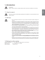
1.2 Warnings
t %POPUPQFSBUFUIFNBDIJOFPSDBSSZPVUSPVUJOFNBJOUFOBODFCFGPSFSFBEJOHUIJT
manual.
t 5IJTNBDIJOFJTEFTJHOFEBOECVJMUGPSTFSWJOHFTQSFTTPDPGGFFIPUXBUFSGPSUIF
QSFQBSBUJPOPGCFWFSBHFTBOEJOGVTJPOT
BOETUFBNVTFEUPIFBUMJRVJET
5IFVTF
PGUIFNBDIJOFGPSBOZPUIFSUIBOJUTJOUFOEFEQVSQPTFTJTDPOTJEFSFEUPCFJNQSPQFSBOEVOBVUIPSJ[FE5IFNBOVGBDUVSFSEFDMJOFTBOZMJBCJMJUZGPSEBNBHFSFTVMUJOH
from the improper use of the machine.
t 5IFVTFSNVTUCFBSFTQPOTJCMFBEVMUXIPJTFYQFDUFEUPDPNQMZXJUIMPDBMTBGFUZ
rules and accepted common sense procedures.
t 5IFNBDIJOFNVTUOFWFSCFVTFEXJUIUIFGJYFEBOEPSNPCJMFHVBSETSFNPWFEPS
XJUIUIFTBGFUZEFWJDFTDVUPGG5IFTBGFUZEFWJDFTNVTUBCTPMVUFMZOFWFSCFSFNPWFEPSUBNQFSFEXJUI5IFQBOFMTDPWFSJOHUIFNBDIJOFNVTUOPUCFSFNPWFEBT
UIFNBDIJOFDPOUBJOTMJWFQBSUTUIFSFJTUIFSJTLPGFMFDUSJDTIPDL
t 4USJDUDPNQMJBODFXJUIUIFSPVUJOFNBJOUFOBODFJOTUSVDUJPOTPGUIJTNBOVBMJTSFRVJred for a safe and efficient operation of the appliance.
t *OUIFFWFOUPGQSPCMFNTPSCSFBLBHFPGBOZDPNQPOFOUPGUIFFTQSFTTPDPGGFF
NBDIJOFDPOUBDUBOBVUIPSJ[FETFSWJDFDFOUSFBOEJOTJTUPOPSJHJOBMTQBSFQBSUT
GSPN-"4"/."3$041"
t *GUIFQPXFSDPSEJTEBNBHFEJUNVTUCFSFQMBDFECZUIFNBOVGBDUVSFSUIFNBOVGBDUVSFSTUFDIOJDBMTFSWJDFPSBTJNJMBSMZRVBMJGJFEQFSTPOTPBTUPQSFWFOUBOZTPSU
PGSJTL
t 5IFVTFSNVTUOFWFSQFSGPSNBOZPQFSBUJPOGPSXIJDIIFTIFJTVOBVUIPSJ[FEPSMBDLT
USBJOJOH$POUBDUUIFNBOVGBDUVSFSGPSBOZJOGPSNBUJPOTQBSFQBSUTPSBDDFTTPSJFT
1.3 Starting the coffee machine
Ambient temperature:
Water pressure:
Water hardness:
5 ÷ 45° C (drain the water system in case of frost)
80 ÷ 800 kPa (0.8 ÷ 8.0 bar)
less than 5° fH
21
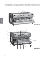
2. Exploded diagrams
ENGLISH
19
20
Mod. 85-S
11
6
7
8
9
10
5
4
3
2
12
1
15
18
22
17
16
13
14
Mod. 85-E
ENGLISH
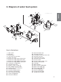
3. Diagram of water feed system
Key to illustrations:
1
2
3
4
5
6
7
8
9
10
11
12
13
14
15
16
17
18
19
20
Main switch
Pilot light
Steam spout
Cup warmer on/off switch
Steam valve lever
Button for serving single strong coffee
Button for serving single weak coffee
Button for serving double strong coffee
Button for serving double weak coffee
Continuous serving button
Hot water valve lever
Espresso coffee serving unit
Filter holding cup with handle
Manual boiler water filling lever
Hot water spout
Gas burner ignition button
Gas burner safety button
Two-scale pressure gauge
Coffee serving button
Visual level indicator
21
22
23
24
25
26
27
28
29
30
31
32
33
34
35
36
37
38
Boiler water drain tap
Automatic level tap
Push button valve with check valve
Automatic level tap
Check and safety valve
Automatic level solenoid
Pressure switch
Pressure switch setting screw
Grounds collecting tray
Drain pipe
Water softener
Water softener feeding pipe
Mains water supply tap
Mains water supply pipe
Pump feeding pipe
Machine feeding pipe
Pump (external model)
Pump (internal model)
23
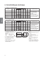
4. Technical specifications
4.1 SEMI-AUTOMATIC MODELS
ENGLISH
MODEL
POWER CONSUMTPION (W)
NO. OF
BOILER
POWER CONNECTION
CUP
BREWING CAPACITY
PUMP
WARMER
UNITS IN LITRES SINGLE PH. TRI-PH.
(Optional)
WEIGHT
(KG)
DIMENS.
A
(MM)
SPECIAL FEATURES
85 - PRACTICAL - S
1
4,9
1750
–
300
–
39
380
85 - SPRINT - S
2
4,9
3000
4500
275
–
56
626
r $PGGFFCSFXJOHJTTUBSUFE
and stopped by a single
pushbutton.
85 - S - 2
2
12
300
100
60
720
r )PUXBUFSBOETUFBN
delivery on all models.
85 - S - 3
3
19
300
125
74
960
85 - S - 4
4
25
300
150
85
1200
WEIGHT
(KG)
DIMENS.
A
(mm)
3500 3500
4500 4500
5500 5500
7000 7000
7000 7000
9000
r "VUPNBUJDXBUFSMFWFM
(boiler is automatically
refilled) on all models.
4.2 AUTOMATIC MODELS
MODEL
POWER CONSUMTPION (W)
NO. OF
BOILER
POWER CONNECTION
CUP
BREWING CAPACITY
PUMP
WARMER
UNITS IN LITRES SINGLE PH. TRI-PH.
(Optional)
SPECIAL FEATURES
r &MFDUSPOJDBMMZDPOUSPMMFE
coffee brewing: four
different automatic portions
can be programmed on
each brewing unit.
85 - PRACTICAL - E
1
4,9
1750
–
300
–
39
380
85 - SPRINT - E
2
4,9
3000
4500
275
–
56
626
85 - E - 2
2
12
300
100
60
720
r )PUXBUFSBOETUFBN
delivery on all models.
85 - E - 3
3
19
300
125
74
960
85 - E - 4
4
25
300
150
85
1200
r "VUPNBUJDXBUFSMFWFM
(boiler is automatically
refilled) on all models.
r 5IFTFNBDIJOFTDBOCFQPXFSFE
with the following voltages:
400V - 3N tri-phase (wire ()
230V - 3
tri-phase (wire ▲)
230V
single-phase
Practical models can be powe red
with 110/230 V single-phase only.
r .PEFMTXJUIGPVSCSFXJOHVOJUT
are available with 3-Triphase input
power requirement only.
r 1VNQCVJMUJOUP413*/5NPEFM
external pump in the other models.
24
3500 3500
4500 4500
5500 5500
7000 7000
7000 7000
9000
Optional accessories
r 8BUFSTPGUFOFSPOBMMNPEFMT
r "VUPNBUJDXBUFSMFWFMCPJMFSJT
automatically refilled).
r (BTGJSJOHPOBMMNPEFMTXJUI
brewing units.
r &MFDUSJDDVQXBSNFSPOBMMNPEFMT
(except for PRACTICAL and
SPRINT) 2-3-4 brewing units.
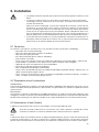
t 5IFJOTUBMMBUJPONVTUCFDBSSJFEPVUCZBVUIPSJ[FE-B4BO.BSDPUFDIOJDBMQFSTPOOFM
t 5IFDPGGFFNBDIJOFJTEFMJWFSFEJOBTVJUBCMFDBSECPBSEBOETUZSPGPBNQBDLJOH
5IFQBDLJOHDPOUBJOTUIFNBDIJOFBOEJUTBDDFTTPSJFTUIFVTFSNBOVBMBOEUIFDPOGPSNJUZEFDMBSBUJPO
"GUFSPQFOJOHUIFQBDLJOHDIFDLUIFQSPQFSDPOEJUJPOPGUIFDPGGFFNBDIJOFBOEJUT
DPNQPOFOUT*ODBTFPGEPVCUEPOPUVTFUIFBQQMJBODFBOEDPOUBDU-B4BO.BSDP
4Q" 5IF QBDLJOH NVTU CF EJTQPTFE PG BU UIF QSPQFS XBTUF DPMMFDUJOH DFOUSFT JO
DPNQMJBODFXJUIMPDBMMBXT%POPUEJTDBSEJOUIFFOWJSPONFOU5IFQBDLJOHFMFNFOUT
DBSUPOTUZSPGPBNOZMPOTUBQMFTFUD
DBOCFBTPVSDFPGIB[BSET,FFQPVUPGSFBDI
of children.
t 5IF NBDIJOF TIPVME CF QMBDFE PO B QFSGFDUMZ IPSJ[POUBM QMBOF TVGGJDJFOUMZ TUVSEZ UP
TVQQPSUUIFXFJHIUPGUIFNBDIJOFXJUIBTVGGJDJFOUDMFBSBODFBSPVOEJUUPEJTTJQBUFUIF
heat generated during its operation.
5.1 Equipment in machine kit
The machine packing contains the equipment kit, which includes the following items:
- filter cups with filter restraint ring
- filters for filter cups (single and double doses)
- blind filter for filter cup
- spouts for filter cups (single and double doses)
- press for ground coffee
- braided 900 mm stainless-steel tube for water connection (water supply - water softener)
- rubber drain hose with steel coil for water drain
- 3/8" nipples for hose connection to water supply tube
- cleaning brush for serving units
- pump suction filter (on request)
- braided 600 mm stainless-steel tube for water connection (pump inflow - water softener) optional only for external pump
- braided 1600 mm stainless-steel tube for water connection (pump outflow - coffee machine) optional only for external pump;
5.2 Prearrangement of water supply
FEEDING LINE
Bring the water feeding tube (of at least 3/8" diameter) up to the machine and install an on-off valve (preferably of 3/8" ball type) that allows a rapid opening and closing operation.
DRAIN LINE
Provide an inspectable drainage pit on the floor connected with the sink drainage line, suitable for receiving
the machine gravity drainage tube.
The drain tube must be positioned so that the water flows out freely, without possibility for the pipe to clog
up during the operation.
5.3 Water softener (optional)
The water softener for the mains water can be manual or automatic, depending on customer's request.
#FGPSFDPOOFDUJOHUIFXBUFSTPGUFOFSUPUIFDPGGFFNBDIJOFUIFSFTJOTDPOUBJOFEJOJUTIPVMECF
XBTIFEPGGBTEFTDSJCFEJOUIFVTFShTNBOVBMTVQQMJFEXJUIUIFBQQMJBODF
/PUF
5IFXBUFSTPGUFOFSJTDPOTJEFSFEBOFTTFOUJBMEFWJDFUPHVBSBOUFFBQSPQFSPQFSBUJPOPGUIFFTQSFTTPDPGGFF
NBDIJOF"XBUFSTPGUFOJOHTZTUFNTIPVMECFQSPWJEFEJOPSEFSUPHVBSBOUFFUIFFGGJDJFODZQFSGPSNBODFBOE
duration of the components in the machine.
25
ENGLISH
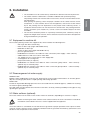
5. Installation
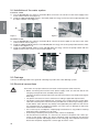
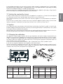
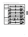
5.4 Installation of the water system
ENGLISH
INTERNAL PUMP
1) Use the braided 900 mm stainless-steel tube 32 to connect the on-off valve of the water supply to the
water softener inflow valve (figure 1).
2) Using the rubber-braided 35 stainless-steel tube (2500 mm long), connect the internal pump intake with
the water softener valve (figure 2).
32
35
Figure 1
Figure 2
EXTERNAL PUMP
1) Use the braided 900 mm stainless-steel tube 32 to connect the water supply on-off valve to the water
softener inflow valve 1 (figure 3).
2) Using the rubber-braided stainless-steel tube 35 (600 mm long), connect the pump intake with the water
softener valve (figures 3-4).
3) Using the rubber-braided stainless-steel tube 36 (1600 mm long), connect the pump outflow with the
nipple 5 of the water system on the machine (figures 4-5).
36
35
Figure 3
Figure 4
35
Figure 5
36
5.5 Drainage
Connect the drainage tube to the grounds collecting tray and to the water drainage system.
5.6 Electrical connections
26
*OTUSVDUJPOTGPSBQSPQFSFMFDUSJDBMDPOOFDUJPOPGUIFFTQSFTTPDPGGFFNBDIJOF
t #FGPSFDPOOFDUJOHUIFNBDIJOFUPUIFQPXFSTVQQMZNBLFTVSFUIBUUIFEBUBPOUIF
SBUJOHUBHDPSSFTQPOEUPUIFBWBJMBCMFQPXFSTVQQMZ
5IFUBHJTMPDBUFEPOUIFMFGUTJEFPGUIFNBDIJOFBOEDBOCFBDDFTTFECZSFNPWJOHUIF
MPXFSUSBZ
t 5IFQPXFSDPOOFDUJPONVTUCFDBSSJFEPVUBDDPSEJOHUPBQQMJDBCMFSFRVJSFNFOUT
t 5IFQPXFSTZTUFNQSFBSSBOHFECZUIFDVTUPNFSNVTUDPNQMZXJUIUIFDVSSFOUBQQMJDBCMFMBXTBOEUIFQPXFSTPDLFUNVTUCFQSPWJEFEXJUIBOFGGJDJFOUHSPVOEJOHTZTUFN
-B4BO.BSDP4Q"EFDMJOFTBOZMJBCJMJUZJGUIFBQQMJDBCMFQSFTDSJQUJPOTPGUIFMBXBSF
OPUDPNQMJFEXJUI"OJNQSPQFSJOTUBMMBUJPODBODBVTFJOKVSZPSEBNBHFGPSXIJDIUIF
manufacturer cannot be held liable.
t *GJUJTOFDFTTBSZUPVTFBEBQUFSTNVMUJQMFQMVHTBOEFYUFOTJPOTPOMZQSPEVDUTNFFUJOH
BQQMJDBCMFTBGFUZTUBOEBSETNVTUCFVTFE
t 5PBWPJEBOZPWFSIFBUJOHPGUIFQPXFSDBCMFVOXJOEJUDPNQMFUFMZ
t 'PS UIF FMFDUSJDBM DPOOFDUJPO JU JT OFDFTTBSZ UP JOTUBMM BO PNOJQPMBS NBJO TXJUDI VQTUSFBN PG UIF QPXFS TVQQMZ UIJT TXJUDI TIPVME CF SBUFE BDDPSEJOH UP UIF FMFDUSJDBM
DIBSBDUFSJTUJDTQPXFSBOEWPMUBHF
TIPXOPOUIFSBUJOHUBH5IFPNOJQPMBSTXJUDINVTU
EJTDPOOFDUUIFQPXFSTVQQMZXJUIBDPOUBDUHBQPGBUMFBTUNN
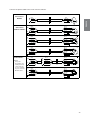
Connect the power cable to the main switch as follows:
N
L
BLUE
BLUE
BROWN
BROWN
YEL/GREEN
YEL/GREEN
230V SINGLE PHASE
ONLY FOR 85
COMPACT MODELS
N
L
2 HEATING ELEMENTS
BLUE
BLACK
BLACK
BLACK
BLACK
BROWN
BROWN
BLUE
YEL/GREEN
YEL/GREEN
400V-3N THREE PHASE
N
L3
L2
L1
3 HEATING ELEMENTS
BLUE
BLUE
BLACK
BLACK
BLACK
BROWN
BROWN
BLACK
YEL/GREEN
YEL/GREEN
230V-3 THREE PHASE
L3
L2
L1
OTHER MODELS
NOTES:
* The power
absorbed by the
heating elements
can be reduced
to 2/3 by eliminating one of the two
BLACK cables.
BLUE
BLACK
BLACK
BLACK
BROWN
BROWN
YEL/GREEN
BLACK
YEL/GREEN
BLUE
BLACK
BLACK
L
BROWN
YEL/GREEN
230V-3 THREE PHASE
L3
L2
L1
3 HEATING ELEMENTS
BLUE
230V SINGLE PHASE
N
ENGLISH
1 HEATING ELEMENT
110V/230V SINGLE PHASE
ONLY FOR 85 1
MODELS
*
400V-3N THREE PHASE
N
L3
L2
L1
3 HEATING ELEMENTS
BLUE
BLUE
BLACK
BLACK
BLACK
BLACK
BROWN
BROWN
YEL/GREEN
YEL/GREEN
3 HEATING ELEMENTS
BLUE
BLUE
BLACK
BLACK
BLACK
BROWN
BROWN
YEL/GREEN
BLACK
YEL/GREEN
27
6. Operating instructions
ENGLISH
6.1 Filling the boiler
Checking the position of the taps in the water system
a) Remove the coffee ground collection tray with grille. Now, check for the following configuration:
r#PJMFSESBJOUBQDMPTFE
r5BQPOUIFBVUPNBUJDMFWFMDPOUSPMWBMWFPQFO
r5BQPOUIFBVUPNBUJDMFWFMDPOUSPMWBMWFPQFO
b) Install the coffee ground collection tray with grille
c) Open the main water fill tap 33
d) Open a steam delivery lever 5 to allow air to escape from the system as the boiler is filled.
Mod. 85 - Practical - S/E
e) Move the main switch 1 to position 1 to fill the boiler automatically without activating the heating elements. When the water reaches the probe, the “MAX” led will light up. When the boiler is full, turn the
main switch to working position 2.
Mod. 85 - S/E - 2 - 3 - 4
f) Make sure that the main switch 1 is in position “zero”.
g) Press and hold down the button 14 until the sight glass 20 is 3/4 full.
6.2 Calibration of pump pressure
a) Once the boiler is filled, turn the main switch to position 2 (the heating elements start to heat the water).
b) Press the continuous-feeding push button 19 for the manual serving machines or the push button 10 for
the electronic machines with automatic serving, so that the water flows out of the unit corresponding to
the pressed button.
c) Read the water pressure value on the lower part of the
pressure gauge 18. The optimum pressure is 9 bar.
PUMP SCREW
The pressure is adjusted to the desired value by operating on the pump screw: the pressure is increased by
turning clockwise; it is decreased by turning counterclockwise. As shown in the following figure, there are
three different cases for adjusting this screw, depending on the pump installed on the machine:
- adjust only the screw
- adjust the screw and lock it with the lock nut
- unscrew the cap nut and adjust the screw.
6.3 Calibration of water pressure in the boiler
a) After having filled the boiler to the proper level, turn the main switch to position 2 (the heating elements
will start to heat the water).
b) Open the lever-controlled steam valve 5 to vent the air during the heating phase. Close the valve as soon
as the steam phase is reached. The steam pressure in the boiler can be read on the upper scale of the
pressure gauge 18 from 0 to 3 bar. The pressure rises to the calibration value of the pressure switch 27
in the range from 0.9 to 1.1 bar. To vary the steam pressure, turn the screw 28 on the pressure switch
27. The pressure is decreased by turning the screw clockwise and it is increased by turning the screw
counterclockwise. The screw is adjusted by means of a screwdriver inserted into the hole on the lid of the
pressure switch. The pressure switch can be reached from the upper tray and grill.
6.4 Heating the water in the boiler
a) Rotate the main switch to position 2.
b) Hold down a steam delivery lever 5 to allow air to escape from the system as the machine heats up.
Release the lever as soon as steam escapes from the delivery pipe. Boiler pressure is indicated on the
0-to-3-bar scale on the pressure gauge 18 (suggested value: 0.9-1.2 bar).
28
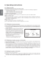
6.5 Electric cup warmer (Optional)
The on/off button 4 is used to heat the cup holding shelf; it can be switched on and off at will.
This function is used to deliver steam from the boiler to heat liquids, or to foam milk for cappuccinos. Lower
or raise the lever 5 to obtain the maximum flow of steam. Move the lever sideways to the left of right to obtain
a reduced steam flow.
6.7 Hot water delivery
The lever-operated tap 11 is used to deliver hot water from the boiler for making tea, camomile herb tea, etc.
This lever operates in the same way as the steam delivery lever.
6.8 Preparation of ground coffee
Make sure that the filter with the desired capacity has been installed in the filter holder. After the coffee has
been loaded and pressed into the filter, the coffee level in the filter must just touch the spray head on the
brewing unit. To check for correct coffee level, install the full filter holder onto the brewing unit and then remove the holder. Now, look at the surface of the coffee: if the level is correct, the coffee will contain the imprint
of the central mounting screw on the spray head of the brewing unit.
6.9 Brewing coffee
Semiautomatic models: 85 - S
Once the filter holder has been installed onto the machine, simply press the switch 19 to actuate the pump
and solenoid valve. When the coffee in the cup has reached the desired level, move the switch back to its
original position to terminate brewing.
Automatic models: 85 - E
Once the filter holder has been installed onto the machine, press one of the five brewing buttons. The first two
buttons 6 and 7 are used to select the two pre-programmed single portions of coffee. The second two buttons
8 and 9 are used to select the two pre-programmed double portions of coffee. The fifth button 10 immediately
shuts down brewing if pressed during a coffee brewing cycle. Button 10 can also be used to brew the desired
quantity of coffee manually: press this button to start brewing, and presse the button a second time to stop
brewing when the desired quantity of coffee has been obtained.
6.10 Draining the boiler
If the boiler must be emptied, shut off the power to the machine by moving the main switch 1 to the “zero”
position. On gas-fired machines, extinguish the flame by closing the gas feed valve. Open the drain tap 21
until the boiler has been completely drained.
Important: be sure to close the tap before refilling the boiler.
6.11 Automatic operation - programming the coffee brewing cycles
Automatic models: 85 - E
A. Entering the programming mode
Set the main switch 1 on the machine to position “zero” (machine switched off).
Hold down the fifth button 10 on the first brewing unit. Now, rotate the main switch 1 to position 1 (machine
switched on). After a few seconds, release the button 10. The indicator led for the button will now begin to
flash, as will the same led on all the other brewing units. The machine is now ready for programming.
B. Programming
To program the four portions on brewing unit I, proceed as follows: place the single-portion filter into the
single-portion filter holder. Use the coffee dispenser to dispense a single portion of coffee into the filter.
Mount the filter holder onto brewing unit I.
Place an espresso cup under the spout on the filter holder.
Press the first button 6 whose portion is to be programmed. When the coffee in the cup reaches the
desired level, press the fifth button 10 to stop brewing.
Follow the same procedure to program the other portions on each group. Once the four portions on brewing unit I have been programmed as desired, the relative data can be transferred to the other brewing
units by pressing the fifth button 10 on each unit. When each button 10 is pressed, the indicator led for
the button will stop flashing and remain steadily lit. This shows that the data on brewing unit I has been
transferred successfully.
29
ENGLISH
6.6 Steam delivery
C. &YJUJOHGSPNUIFQSPHSBNNJOHNPEF
After you have finished programming the machine, press the button 10 (with flashing led) on brewing unit I
and all the leds will turn off. The programmed quantity of coffee will now be delivered when an automatic
brewing button is pressed.
ENGLISH
6.12 Important information on daily maintenance
To keep your espresso machine in top operating condition and obtain maximum performance, the followint
cleaning operations must be performed on the brewing units at the end of the work day:
a) Install the blank filter (without holes) into the filter holder. This filter is provided with the machine.
b) Install the filter holder with blank filter onto the brewing unit to be cleaned but do not tighten the holder,
thus allowing water to overflow at the sides. Push the continuous brewing button and let the water run
for about a minute. This will clean the spray head and the water delivery pipe in the unit.
c) Tighten the filter holder onto the brewing unit so that water can no longer overflow at the sides. Manually
run the unit once again for around 5 seconds, and then shut the unit down. Repeat this operation 5 or 6
times to clean the solenoid valve and the drain pipe on the unit.
/PUF To clean the brewing units more thoroughly, the blank filter can be filled with one of the special detergents that are available on the market.
6.13 Alarms
A flashing Led on the first button of pushbutton array indicates a malfunction on the flow meter.
A flashing Led on the second button of all the pushbutton arrays indicates a malfunction on the automatic
boiler refill system (jammed solenoid valve, insufficient water from the main water system, etc.). After 1’30”,
the pump motor will shut down.
Note: If the machine shuts down as described above, call your local service technician.
t %POPUVTFXBUFSTQSBZTTUFBNPSTJNJMBSDMFBOJOHNFUIPET#FGPSFDMFBOJOHPSNBJOUFOBODFPQFSBUJPOT%*4$0//&$55)&$"#-&*'1044*#-&05)&38*4&4)650''
5)&0./*10-"3."45&348*5$)*/45"--&%")&"%0'5)&."$)*/&
t *G QPXFS DBCMF JT EBNBHFE JU NVTU CF SFQMBDFE XJUI UIF TQFDJBMMZ QSFQBSFE PSJHJOBM
FRVJQNFOUSFQMBDFNFOUQBSUXIJDIDPOGPSNTUPTBGFUZSFHVMBUJPOT
t 4QFDJBMNBJOUFOBODFQBSUTSFQMBDFNFOUMPOHUFSNTPVUEPXOBOEEJTQMBOUJOHPQFSBtions must be performed bZ-"4"/."3$0TFSWJDFQFSTPOOFM
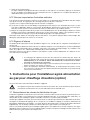
7. Instructions for Authorized Installer Gas fired
Boiler (Optional)
Read the instructions before installing and using the appliance.
5IJTBQQMJBODFDBOPOMZCFJOTUBMMFEBOEVTFEJOQFSNBOFOUMZWFOUJMBUFEQMBDFTBDDPSEJOHUP6/*
$*(BOE6/*$*(4UBOEBSET
7.1 Connection to gas supply
Position the appliance as described in the Use and Maintenance Manual, remove the control panel as described in the same handbook, and connect the appliance to the gas supply mains, or LPG bottle (G30/G31),
using rigid metal pipes or flexible metal tubes according to UNI-CIG 9891 Standards.
Check that the appliance is prearranged for the type of gas actually being used; the corresponding setting is
shown on the settings tag.
If the appliance is prearranged for a different type of gas, change the arrangement as described in the paragraph “Changing the calibration”.
The gas infeed, consisting of an on-off valve (51), includes a G 1/8” threaded connection (thread is not gastight) according to ISO 228-1 Standard.
If using rigid metal pipes for connection to the gas supply, place an appropriate fitting between the valve and
the rigid metal pipe, which should be provided with a G 1/8” female thread (thread is not gas-tight) according
to ISO 228-1 Standard.
30
7.2 Venting the combustion fumes
In relation to the venting of the combustion fumes, the appliance is of Type A1: i.e., it draws in the air required
for combustion from the room and discharges the fumes in the same environment.
Place particular attention to the volume of the room where the appliance is to be installed: this should be at
least 12 m3.
If the room has a smaller volume, it will be necessary to install the appliance directly under a suction hood,
and also to provide a combustion air intake with a free-flow cross section of al least 100 cm2.
7.3 Ignition
Press and turn the gas valve knob (51) counterclockwise to the position of the flame symbol, as shown in Fig.
B. While holding the knob pressed, push a few times the burner ignition button, marked with the star symbol
(53) to ignite the burner (piezoelectric ignition).
When the flame is lit, check through the relative hole (54), while keeping the gas knob pressed for 5-10 seconds. After this period, if the flame does not remain lit, repeat the ignition operation again.
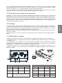
7.4 Changing the calibration
The appliance is prearranged to operate with the gas indicated in the relative settings tag attached to the
appliance. The information regarding the air setting, injector, rated and reduced heat flow are shown in Tables
1 and 2. The data that correspond with each model are indicated by the next-to-last character of the code for
the relative model. For example, the model code shown on the tag for the gas part characteristic 85-E-3-G
shows number 3 in the next-to-last digit.
In this case, refer to the data shown in Tables 1 and 2, respectively, in the column headed “3 Units”.
If you wish to change the calibration of the appliance, proceed as follows:
Unscrew the primary air adjusting ring nut (55 - Fig. C) to expose the nozzle (56). Using the relative wrench,
unscrew the nozzle (56) and replace it with the proper one indicated in Table 2, checking that the diameter
marked on the same nozzle corresponds to the right diameter.
2° GRUPPO
1° GRUPPO
2
0
1
1
53
51
54
Table 1 - Adjusting the primary air (Fig. C)
Gas
2 Units
3 Units
4 Units
GPL
(G30/G31)
L = 8 mm
L = 10 mm L = 12 mm
Nat. gas
(G20)
L = 4 mm
L = 4 mm
Table 2 - Nozzle diameters in 100/mm
Gas
2 Units
3 Units
4 Units
GPL
(G30/G31)
40
55
65
Nat. gas
(G20)
60X
81X
90X
Qn = Rated heat flow
Qn (kW)
0,75
1,45
1,9
Qnr = Reduced rated heat flow
Qnr (kW)
N.A.
1,0
1,3
L = 4 mm
31
ENGLISH
If using flexible metal tubes for connection to the gas supply, interpose an appropriate G 1/2” female nipple
(gas-tight thread) according to ISO 7-1 Standard and a G 1/2” male nipple (thread is not gas-tight) according
to ISO 228-1 Standard; interpose a suitable gas-tight gasket.
When the connection is completed, open the gas flow upstream of the appliance and, using a soapy solution
(never a free flame), check the perfect tightness of the connection.
ENGLISH
Screw on the new nozzle (56), and position the primary air adjusting ring nut (55 - Fig. C) according to the
indications of Table 1, using a gauge or equivalent instrument to set the distance “L”, and tighten the screw
provided to fasten the nozzle.
Turn the main switch (1) to position 1, so as to connect a single heating element (50% of the boiler’s electric
power for single-phase heating element with 2 elements and 1/3 of power for heating elements with 3 elements with three-phase connection), and ignite the burner as in the procedure described above. When the
water contained in the boiler reaches the preset temperature, the gas flow regulator will automatically decrease the flow to the value corresponding to the reduced rated heat flow.
At this point, turn the flow regulation screw (58) so as to have a steady flame licking the sensitive thermocouple element (52), and turn the screw (57) to obtain the maximum desired pressure value in the boiler.
After having verified the proper operation, replace the settings tag on the appliance with the one for the new
type of gas that is provided with the standard kit containing the newly installed gas nozzle.
Safety devices on appliance (manually reset).
The appliance is provided with two safety devices that shut off the gas flow if the flame accidentally goes out.
1 - Termocouple (52): The thermocouple operates on the valve (51), whose probe (52) must be licked by
the flame from the burner (50). If the probe is not enveloped by the flame, the gas flow will be automatically shut off.
2 - Thermostat (59): The thermostat, placed in contact with the boiler, operates on the valve (51); when the
thermostat sensor on the boiler reads 140˚C, the gas flow will be automatically shut off.
The burner can be re-ignited with the procedure described above only after the boiler body has cooled to
110˚C. Following the activation of one of the two safety devices, try re-igniting the burner with the procedure
already described.
*GUIFNBMGVODUJPOQFSTJTUTBOEUIFCVSOFSDPOTFRVFOUMZDPOUJOVFTUPHPPGGDPOUBDUUIFOFBSFTU
BVUIPSJ[FE4FSWJDFPVUMFUXIJDIXJMMQSPWJEFUPFMJNJOBUFUIFDBVTFPGUIFNBMGVODUJPO
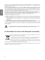
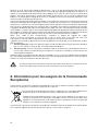
8. Information for users in the European community
Pursuant to European Directive 2002/96/EC on electrical waste (WEEE), users in the European community are advised of the following.
The symbol with the crossed-out dustbin on the appliance or its packaging indicates that at
the end of the product’s life cycle, it must be collected separately from other waste.
Suitable separate collection of the equipment for subsequent recycling, treatment and disposal contributes to preventing possible negative consequences for the environment and
health, and favours the recycling of materials that the unit is made of.
In accordance with European Directive 2002/96/EC, abusive disposal of the product by the user will result in
application of penalties as set forth by local law.
32
The warranty becomes void if:
r 5IFJOTUSVDUJPOTJOUIJTNBOVBMBSFOPUDPNQMJFEXJUI
r 5IFTDIFEVMFENBJOUFOBODFBOESFQBJSTBSFDBSSJFEPVUCZVOBVUIPSJ[FEQFSTPOOFM
r 5IFNBDIJOFJTVTFEGPSBOZPUIFSUIBOJUTJOUFOEFEQVSQPTFT
r 5IFPSJHJOBMQBSUTBSFSFQMBDFEXJUIQBSUTGSPNEJGGFSFOUNBOVGBDUVSFST
r 5IFXBSSBOUZEPFTOPUDPWFSEBNBHFDBVTFECZOFHMFDUVTFBOEJOTUBMMBUJPOOPUJODPNQMJBODFXJUIUIF
recommendations of this manual, improper operation, abuse, lightning and atmospheric phenomena,
overvoltage, overcurrent, or insufficient or irregular power supply.
10. Declaration of conformity
The manufacturer:
La San Marco S.p.A.
34072 Gradisca d’Isonzo (GO) Italy – Via Padre e Figlio Venuti, 10
phone (+39) 0481 967111 – fax (+39) 0481 960166 – http://www.lasanmarco.com
declares under its own responsibility that the espresso coffee machine described in this manual and identified by the data on the tag located on the machine, is compliant with directives 98/37/EC, 2006/95/EC,
89/336/EEC, Regulation (EC) No 1935/2004. For verification of compliance with said directives, the following
harmonized standards have been applied: EN 12100-1, EN 12100-2, EN 60335-1, EN 60335-2-75
Gradisca d’Isonzo, April 2009
Managing director
Mr Roberto Marri
33
ENGLISH
9. Guarantee
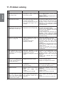
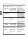
11. Problem solving
ENGLISH
PROBLEM
CAUSE
SOLUTION
1.
The boiler is full of water
r0OF PG UIF PVUGMPX MJOFT GSPN r$IFDLUIFBVUPMFWFMDJSDVJUUIFNBOand the water flows out of
the boiler or from a circuit of ual charging button, and the boiler
the safety valve.
the unit has a leak.
heat exchangers.
r3FQMBDF XPSO PS EBNBHFE QBSUT UP
eliminate the leak.
2.
The safety valve trips in
and vents the steam.
3.
The machine was started r5IFFMFDUSJDIFBUJOHFMFNFOUJT r$IFDL JG UIF IFBUJOH FMFNFOU JT DPOproperly but the water in the defective or is not connected.
nected to the power supply.
boiler does not warm up.
r$IFDL JG UIF IFBUJOH FMFNFOU TBGFUZ
thermostat has tripped in and check
its proper operation.
r*O UIF NBDIJOFT XJUI FMFDUSPOJD UFNperature control, check the proper
operation of the electronic control
unit, the triac, the level probe, and the
electrical wiring.
4.
There is no water flowing r$PGGFF HSPVOE UPP GJOF PS r"EKVTU UIF HSJOEJOH DPBSTFOFTT BOE
from a serving unit.
excessive quantity for type of or the quantity of ground coffee.
filter used.
r$IFDL UIBU UIF JOKFDUPS UIF VQQFS
r$MPHHFEXBUFSDJSDVJU
circulation tube, the spray nozzle
r%FGFDUJWFTPMFOPJE
and the solenoid of the unit are not
clogged.
r*OUIFNBDIJOFTXJUIFMFDUSPOJDNFUFSing, check the displacement meter
and its valves.
r$IFDL UIF TPMFOPJE PG UIF VOJU JUT
wiring and the fuse in the electronic
control unit.
5.
The programmed servings r"COPSNBM PQFSBUJPO PG UIF r1SPHSBNUIFTFSWJOHRVBOUJUJFTTFQBof espresso coffee are not electronic control unit or of the rately on each serving unit. If the
constant or vary on the dif- displacement counters.
problem persists, replace the disferent units.
r-FBLGSPNTFSWJOHVOJUTPMFOPJE placement meter of the serving unit
valve.
affected.
r3FQMBDF UIF TPMFOPJE WBMWF PG UIF
serving unit.
6.
It is not possible to pro- rAbnormal operation or defective r$IFDL UIF DPOUSPM VOJUEJTQMBDFNFOU
gram the serving quantities displacement meter of unit 1.
meters electrical wiring.
on unit 1 and to copy them
r3FQMBDFUIFEJTQMBDFNFOUNFUFS
on the other units.
7.
Displacement meters alarm. r%JTQMBDFNFOU NFUFST KBNNFE r3FQMBDFUIFEJTQMBDFNFOUNFUFS
or defective.
r$IFDLUIFXJSJOHBOEJUTDPOOFDUJPOT
r%FGFDUJWFXJSJOH
the control unit and the fuses.
8.
Autolevel alarm.
9.
The machine is switched on r5IFFMFDUSJDXJSJOHPGUIFFMFD- rCheck the electrical wiring, the electronic control unit and its compo(the main switch is in posi- tronic control unit is defective.
tion 1 or 2 and the signal r5IF FMFDUSPOJD DPOUSPM VOJU JT nents.
r3FQMBDFUIFFMFDUSPOJDDPOUSPMVOJU
light is lit) but the electronic defective.
control is out of order.
34
rMalfunction of electrical system rCheck the wiring that feeds the heat(the electrical heating element ing element and the pressure switch.
is always connected).
r*O UIF NBDIJOFT XJUI FMFDUSPOJD UFNr1SFTTVSF JODSFBTF JO UIF CPJMFS perature control, check the proper
(the safety valve trips in at 1.9- operation of the electronic control
2.5 bar).
unit, the triac, the level probe, and the
electrical wiring.
r-BDL PG XBUFS JO UIF BVUPMFWFM r$IFDL UIF IZESBVMJD DJSDVJU PG UIF
circuit.
autolevel.
r.BJO XBUFS TVQQMZ WBMWF r$IFDLJGUIFPOPGGWBMWFPOUIFXBUFS
supply is open.
closed.
r3FQMBDFUIFBVUPMFWFMTPMFOPJE
r'BVMUZBVUPMFWFMTPMFOPJE
PROBLEM
CAUSE
SOLUTION
10. The machine feeds water r4PMFOPJEBOEPSQVNQGFEDPO- rShort-circuited control unit relay.
r3FQMBDFUIFFMFDUSPOJDDPOUSPMVOJU
from one serving unit tinuously.
although the serving has
not been selected.
ENGLISH
11. 85 S models: one unit r&MFDUSJD DJSDVJU PG VOJU JNQSPQ- r$IFDL UIF DPOOFDUJPO BOE DPSSFDU JU
(see wiring diagram).
erly connected.
serves water continuously.
12. The steamer discharges r8PSOHBTLFUPOUBQ
only small quantities of
steam or water droplets.
r3FQMBDFUIFHBTLFU
13. Small drops flow out of the r8PSOHBTLFUPOUBQ
r-FBLGSPNTPMFOPJE
water tap.
r3FQMBDFUIFHBTLFU
r$IFDL UIF TPMFOPJE BOE JG OFDFTTBSZ
replace it.
14. The unit emits a whistle r'BVMUZ PQFSBUJPO PG FYQBOTJPO r$IFDL UIF FYQBOTJPO WBMWF BOE JG
necessary replace it. Calibrate the
valve.
after serving the coffee.
valve at 12 bar.
r)JHIQVNQQSFTTVSF
r$IFDLUIFQVNQPQFSBUJOHQSFTTVSF
Calibrate the pump at 9 bar.
15. The filter cup comes off the r8PSO HBTLFU VOEFS UIF GJMUFS r3FQMBDFUIFHBTLFU
rClean the serving unit and the filter cup.
cup.
serving unit.
16. When coffee is being served, r8PSO HBTLFU VOEFS UIF GJMUFS r3FQMBDFUIFHBTLFU
r$MFBO UIF TFSWJOH VOJU BOE UIF GJMUFS
some of it drips out of the cup.
cup.
edge of the filter cup.
r$IFDLUIFVOJUTPMFOPJE
17. Water leaking from the rMalfunctioning unit solenoid.
drain of the serving unit r8BUFSMFBLJOHGSPNVOJUDPPMJOH r$IFDL UIF QMVOHFS PO UIF TPMFOPJE
and clean the solenoid.
system.
solenoid.
r3FQMBDFUIFTPMFOPJE
r$IFDL UIF DPPMJOH UVCF BOE UIF TFBM
rings inside the unit.
18. Light cream (the coffee a. Coarse grinding.
flows out of the spout b. Low pressing pressure.
c. Small quantity of ground cofrapidly).
fee.
d. Water temperature below 90°C.
e. Pump pressure above 9 bar.
f. Sprinkler filter on unit clogged.
g. Filter holes widened (filter cup).
a.
b.
c.
d.
e.
f.
19. Dark cream (the coffee a. Fine grinding.
b. High pressing pressure.
drips out of the spout).
c. Large quantity of ground coffee.
d. High percolation water temperature.
e. Pump pressure below 9 bar.
f. Sprinkler filter on unit clogged.
g. Filter holes clogged (filter cup).
a.
b.
c.
d.
e.
f.
20. Presence of grounds in cof- a. Coffee ground too fine.
b. Worn grinders in grinder-disfee cup.
penser unit.
c. Pump pressure above 9 bar.
d. Sprinkler filter on unit clogged.
e. Filter holes widened (filter cup).
a.
b.
c.
d.
21. Coffee with too little cream r 4QSJOLMFS
clogged.
in cup (spurts out of spout).
GJMUFS
PO
Finer grinding.
Increase the pressure.
Increase the quantity of ground coffee.
Increase the pressure in the boiler.
Decrease the pump pressure.
Check and clean with blind filter or
replace.
g. Check and replace the filter.
Coarser grinding.
Reduce the pressure.
Decrease the quantity of ground coffee.
Decrease the boiler pressure.
Increase the pump pressure.
Check and clean with blind filter or
replace.
g. Check and replace the filter.
Coarser grinding.
Replace the grinders.
Decrease the pump pressure.
Check and clean with blind filter or
replace.
e. Check and replace filter.
VOJU r $IFDL BOE DMFBO XJUI CMJOE GJMUFS PS
replace.
22. The cream in the cup is too r $PGGFFFYUSBDUJPOUBLFTBMPOH r $MFBOPSSFQMBDFUIFGJMUFS
r $MFBOPSSFQMBDFUIFTQSJOLMFSGJMUFS
time due to clogged filter.
thin (it disappears after a
r $PGGFFFYUSBDUJPOUPPGBTUEVF r -PXFSUIFUFNQFSBUVSFJOUIFCPJMFS
few seconds).
to clogged sprinkler filter.
r 8BUFSUFNQFSBUVSFUPPIJHI
23. Presence of depressions in r 4QSJOLMFSGJMUFSQBSUMZDMPHHFE r $MFBOPSSFQMBDFUIFTQSJOLMFSGJMUFS
the coffee grounds (looking r -PXBNPVOUPGHSPVOEDPGGFF r "EKVTU UIF BNPVOU PG HSPVOE DPGfee.
for the fiter used.
inside the filter cup).
/PUF*GJUJTOPUQPTTJCMFUPTPMWFUIFQSPCMFNBTEFTDSJCFEBCPWFPSJGPUIFSNBMGVODUJPOTEFWFMPQDPOUBDU
UIFBVUIPSJ[FE-B4BO.BSDPTFSWJDFDFOUSF
35
FRANÇAIS
MANUEL D’UTILISATION ET D’ENTRETIEN
SÉRIE 85 / S-E
FRANÇAIS
Index général
1.
Introduction . . . . . . . . . . . . . . . . . . . . . . . . . . . . . . . . . . . . . . . . . . . . . . . . . . . . pag.
1.1 Consultation du manuel . . . . . . . . . . . . . . . . . . . . . . . . . . . . . . . . . . . . . . . . . . . . pag.
1.2 Recommandations . . . . . . . . . . . . . . . . . . . . . . . . . . . . . . . . . . . . . . . . . . . . . . . . pag.
1.3 Utilisation de la machine à café express . . . . . . . . . . . . . . . . . . . . . . . . . . . . . . . pag.
39
39
39
39
2.
3.
4.
Illustration en perspective des différents modèles . . . . . . . . . . . pag.
Schéma de l’alimentation hydraulique . . . . . . . . . . . . . . . . . . . . . . . . pag.
Caractéristiques technique . . . . . . . . . . . . . . . . . . . . . . . . . . . . . . . . . . . . pag.
40
41
5.
Installation . . . . . . . . . . . . . . . . . . . . . . . . . . . . . . . . . . . . . . . . . . . . . . . . . . . . . . pag.
5.1 Fourniture . . . . . . . . . . . . . . . . . . . . . . . . . . . . . . . . . . . . . . . . . . . . . . . . . . . . . . . pag.
5.2 Préparation circuit hydraulique . . . . . . . . . . . . . . . . . . . . . . . . . . . . . . . . . . . . . . pag.
5.3 Adoucisseur d'eau (Option) . . . . . . . . . . . . . . . . . . . . . . . . . . . . . . . . . . . . . . . . . pag.
5.4 Montage installation hydraulique . . . . . . . . . . . . . . . . . . . . . . . . . . . . . . . . . . . . . pag.
5.5 Évacuation . . . . . . . . . . . . . . . . . . . . . . . . . . . . . . . . . . . . . . . . . . . . . . . . . . . . . . pag.
5.6 Branchement électrique . . . . . . . . . . . . . . . . . . . . . . . . . . . . . . . . . . . . . . . . . . . . pag.
43
43
43
43
44
44
44
6.
Instructions pour le fonctionnement de la machine
à café express. . . . . . . . . . . . . . . . . . . . . . . . . . . . . . . . . . . . . . . . . . . . . . . . . . pag.
42
4.1 SEMI-AUTOMATIQUES . . . . . . . . . . . . . . . . . . . . . . . . . . . . . . . . . . . . . . . . . . . . pag. 42
4.2 AUTOMATIQUES . . . . . . . . . . . . . . . . . . . . . . . . . . . . . . . . . . . . . . . . . . . . . . . . . pag. 42
6.1 Remplissage de la chaudière . . . . . . . . . . . . . . . . . . . . . . . . . . . . . . . . . . . . . . . . pag.
6.2 Réglage de la pression d’alimentation de la pompe . . . . . . . . . . . . . . . . . . . . . . pag.
6.3 Réglage de la pression de l’eau dans la chaudière . . . . . . . . . . . . . . . . . . . . . . . pag.
6.4 Chauffage de l’eau dans la chaudière . . . . . . . . . . . . . . . . . . . . . . . . . . . . . . . . . pag.
6.5 Chauffe-tasses électrique (en option) . . . . . . . . . . . . . . . . . . . . . . . . . . . . . . . . . pag.
6.6 Prise de vapeur . . . . . . . . . . . . . . . . . . . . . . . . . . . . . . . . . . . . . . . . . . . . . . . . . . pag.
6.7 Prise d’eau chaude . . . . . . . . . . . . . . . . . . . . . . . . . . . . . . . . . . . . . . . . . . . . . . . pag.
6.8 Préparation du café . . . . . . . . . . . . . . . . . . . . . . . . . . . . . . . . . . . . . . . . . . . . . . . pag.
6.9 Distribution du café . . . . . . . . . . . . . . . . . . . . . . . . . . . . . . . . . . . . . . . . . . . . . . . pag.
6.10 Vidange de la chaudière. . . . . . . . . . . . . . . . . . . . . . . . . . . . . . . . . . . . . . . . . . . pag.
6.11 Fonctionnement automatique - programmation des doses. . . . . . . . . . . . . . . . pag.
6.12 Normes importantes d’entretien ordinaire . . . . . . . . . . . . . . . . . . . . . . . . . . . . . pag.
6.13 Signaux d’alarme . . . . . . . . . . . . . . . . . . . . . . . . . . . . . . . . . . . . . . . . . . . . . . . . pag.
7.
Instructions pour l’installateur agréé alimentation
au gaz pour chauffage chaudière (option) . . . . . . . . . . . . . . . . . . . . . .pag.
7.1 Raccordement au réseau de distribution du gaz . . . . . . . . . . . . . . . . . . . . . . . . . pag.
7.2 Évacuation des produits de la combustion . . . . . . . . . . . . . . . . . . . . . . . . . . . . . pag.
7.3 Allumage . . . . . . . . . . . . . . . . . . . . . . . . . . . . . . . . . . . . . . . . . . . . . . . . . . . . . . . pag.
7.4 Modification du réglage . . . . . . . . . . . . . . . . . . . . . . . . . . . . . . . . . . . . . . . . . . . . pag.
Information pour les usagers
de la Communauté Européenne . . . . . . . . . . . . . . . . . . . . . . . . . . . . . . . pag.
9. Garantie . . . . . . . . . . . . . . . . . . . . . . . . . . . . . . . . . . . . . . . . . . . . . . . . . . . . . . . . pag.
10. Déclaration de conformité . . . . . . . . . . . . . . . . . . . . . . . . . . . . . . . . . . . . pag.
11. Problèmes et solutions . . . . . . . . . . . . . . . . . . . . . . . . . . . . . . . . . . . . . . . . pag.
46
46
46
46
46
47
47
47
47
47
47
47
48
48
48
48
49
49
49
8.
Code manuel: 7770.003
Révision 04/09
38
50
51
51
52
1. Introduction
ATTENTION
"WBOUEVUJMJTFSMBNBDIJOFËDBGÏMJSFBUUFOUJWFNFOUUPVUFTMFTJOTUSVDUJPOTSFQPSUÏFTTVSDFNBOVFM
1.1 Consultation du manuel
1.2 Recommandations
t /FQBTNFUUSFMBNBDIJOFFOGPODUJPOOJFGGFDUVFSMFOUSFUJFOPSEJOBJSFTBOTBWPJSQSÏBMBblement lu ce manuel.
t $FUUF NBDIJOF B ÏUÏ QSPKFUÏF FU DPOTUSVJUF QPVS MB QSPEVDUJPO EF DBGÏ FYQSFTT EFBV
DIBVEFQPVSQSÏQBSFSEFTCPJTTPOTFUEFTJOGVTJPOT
FUEFWBQFVSEFBVQPVSSÏDIBVGGFS
EFT MJRVJEFT
5PVU FNQMPJ EJGGÏSFOU EF DFVY RVJ TPOU EÏDSJUT EBOT DF NBOVFM EPJU ÐUSF
DPOTJEÏSÏDPNNFJNQSPQSFFUEPODOPOBVUPSJTÏ-FDPOTUSVDUFVSEÏDMJOFUPVUFSFTQPOTBCJMJUÏQPVSMFTEPNNBHFTEÏSJWBOUEFMVUJMJTBUJPOJNQSPQSFEFMBNBDIJOF
t -VUJMJTBUFVSEPJUÐUSFVOFQFSTPOOFBEVMUFFUSFTQPOTBCMFRVJEPJUTFOUFOJSBVYOPSNFTEFTÏDVSJUÏFOWJHVFVSEBOTMFQBZTEJOTUBMMBUJPOBJOTJRVBVYSÒHMFTEJDUÏFTQBSMF
bon sens.
t *MFTUSJHPVSFVTFNFOUJOUFSEJUEFGBJSFGPODUJPOOFSMBNBDIJOFBWFDMFTQSPUFDUJPOTGJYFT
FUPVNPCJMFTEÏNPOUÏFTPVBWFDMFTEJTQPTJUJGTEFTÏDVSJUÏFYDMVTJMFTUSJHPVSFVTFNFOUJOUFSEJUEFOMFWFSPVEFNPEJGJFSMFTEJTQPTJUJGTEFTÏDVSJUÏ"VDVOEFTQBOOFBVY
DPOTUJUVBOUMBDBSSPTTFSJFEFMBNBDIJOFOFEPJUÐUSFFOMFWÏSJTRVFEFEÏDIBSHFTÏMFDUSJRVFT
t -FSFTQFDUTDSVQVMFVYEFTPQÏSBUJPOTEFNBJOUFOBODFPSEJOBJSFJOEJRVÏFTEBOTMFQSÏTFOUNBOVFMFTUOÏDFTTBJSFQPVSUSBWBJMMFSFOUPVUFTÏDVSJUÏFUQPVSNBJOUFOJSMBNBDIJOFFOCPOÏUBUEFNBSDIF
t &ODBTEFQBOOFPVEFSVQUVSFEVODPNQPTBOUEFMBNBDIJOFËDBGÏFYQSFTTTBESFTTFS Ë VO DFOUSF EF TFSWJDF BQSÒTWFOUF BHSÏÏ FU EFNBOEFS MVUJMJTBUJPO EF QJÒDFT EF
SFDIBOHFPSJHJOBMFT-"4"/."3$041"
t 4JMFDÉCMFEBMJNFOUBUJPOFTUFOEPNNBHÏJMEPJUÐUSFSFNQMBDÏQBSMFDPOTUSVDUFVSPV
QBSMFTFSWJDFBQSÒTWFOUFBHSÏÏEBOTUPVTMFTDBTQBSVOUFDIOJDJFORVBMJGJÏEFNBOJÒSF
ËQSÏWFOJSUPVUSJTRVFEBDDJEFOU
t *MFTUTUSJDUFNFOUJOUFSEJUEFQSPDÏEFSËEFTPQÏSBUJPOTOPOBVUPSJTÏFTFUTJMFTNPEBMJUÏTFYBDUFTOPOUQBTÏUÏDPNQSJTFTDPOUBDUFSMFDPOTUSVDUFVSQPVSUPVUFJOGPSNBUJPO
pièces de rechange et accessoires.
1.3 Utilisation de la machine à café express
Température ambiante:
5 ÷ 45° C (vider le circuit hydraulique en cas de gel)
Pression eau circuit hydraulique: 80 ÷ 800 kPa (0.8 ÷ 8.0 bars)
Dureté de l’eau:
inférieure à 5° fH
39
FRANÇAIS
-FQSÏTFOUNBOVFMGPVSOJUUPVUFTMFTJOGPSNBUJPOTOÏDFTTBJSFTQPVSMJOTUBMMBUJPOMVUJMJTBUJPOFUMB
NBJOUFOBODFEFMBNBDIJOFËDBGÏ
2. Illustration en perspective des différents modèles
19
FRANÇAIS
20
Mod. 85-S
11
6
7
8
9
10
5
4
3
2
12
1
15
18
40
17
16
13
14
Mod. 85-E
FRANÇAIS
3. Schéma de l’alimentation hydraulique
Legende:
1
2
3
4
5
6
7
8
9
10
11
12
13
14
15
16
17
18
19
20
Interrupteur général
Voyant alimentation
Tuyau de prélèvement vapeur
Interrupteur on/off chauffe-tasses
Levier du robinet de prélèvement vapeur
Bouton de production café unitaire serré
Bouton de production café unitaire allongé
Bouton de production café double serré
Bouton de production café double allongé
Bouton de production continue
Levier du robinet de prélèvement eau chaude
Groupe de production café express
Porte-filtre avec poignée
Levier de remplissage manuel eau chaudière
Tuyau de prélèvement eau chaude
Bouton d’allumage chauffage au gaz
Bouton de sécurité chauffage au gaz
Manomètre à double échelle
Bouton de production café
Indicateur de niveau optique
21
22
23
24
25
26
27
28
29
30
31
32
33
34
35
36
37
38
Robinet de vidange chaudière
Robinet niveau automatique
Robinet à poussoir avec clapet de retenue
Robinet niveau automatique
Soupape de retenue et de sécurité
Électrovanne niveau automatique
Pressostat
Vis de réglage pressostat
Bac de récupération marc de café
Tuyau de vidange
Adoucisseur
Tuyau d’alimentation adoucisseur
Robinet d’arrivée d’eau
Tuyau d’arrivée d’eau
Tuyau d’alimentation pompe
Tuyau d’alimentation machine
Pompe (modèle externe)
Pompe (modèle interne)
41
4. Caractéristiques technique
4.1 SEMI-AUTOMATIQUES
FRANÇAIS
MODÈLE
POTENZA ASSORBITA (W)
CAPACITÉ
N.
CONNEXION AU RÉS.
CHAUFFECHAUDIÉRE
GROUPES
POMPE
TASSES
LITRES MONOPH. TRIPH.
(Optional)
POIDS
(KG)
DIMENS.
A
(MM)
85 - PRACTICAL - S
1
4,9
1750
–
300
–
39
380
85 - SPRINT - S
2
4,9
3000
4500
275
–
56
626
85 - S - 2
2
12
300
100
60
720
85 - S - 3
3
19
300
125
74
960
85 - S - 4
4
25
300
150
85
1200
POIDS
(KG)
DIMENS.
A
(mm)
3500 3500
4500 4500
5500 5500
7000 7000
7000 7000
9000
PERFORMANCES SPÉCIALES
r %JTUSJCVUJPOEJDBGÊBWFDMB
touche Marche/Arrêt.
r 1SJTFEFBVDIBVEFFU
de vapeur sur tous les
modèles.
r /JWFBVBVUPNBUJRVF
(remplissage automatique
de l’eau dans la chaudière)
pour tous les modèles.
4.2 AUTOMATIQUES
MODÈLE
POTENZA ASSORBITA (W)
CAPACITÀ
N.
CONNEXION AU RÉS.
CHAUFFECALDAIA
GROUPES
POMPE
TASSES
(Litri)
MONOPH. TRIPH.
(Optional)
85 - PRACTICAL - E
1
4,9
1750
–
300
–
39
380
85 - SPRINT - E
2
4,9
3000
4500
275
–
56
626
85 - E - 2
2
12
300
100
60
720
85 - E - 3
3
19
300
125
74
960
85 - E - 4
4
25
300
150
85
1200
r -FTNBDIJOFTÆDBGÊFYQSFTT
sont prédisposé pour les tensions
suivantes:
400V - 3N triphase (résist. ()
230V - 3
triphase (résist. ▲)
230V
monophase
r -FTNPEÍMFT1SBDUJDBMTFVMFNFOU
pour: 110/230V monophase
r -FTNPEÍMFTÆRVBUSFHSPVQT
seulment triphasés.
r 1PNQFJODPSQPSÊFEBOTMFNPEÍMF
SPRINT; pompe extérieure dans
les autres modèles.
42
3500 3500
4500 4500
5500 5500
7000 7000
7000 7000
9000
PERFORMANCES SPÉCIALES
r %JTUSJCVUJPOEVDBGÊÆ
dosage électronique avec
possibilité de mémoriser
4 doses différentes pour
chaque groupe.
r Prise d’eau chaude et de
vapeur sur tous les modèles.
r /JWFBVBVUPNBUJRVF
(remplissage automatique
de l’eau dans la chaudière)
pour tous les modèles.
En option
r "EPVDJTTFVSEFBVQPVSUPVTMFT
modèles.
r "VUPSÊHMBHFEVOJWFBV
(remplissage automatique de la
chaudière).
r %JTQPTJUJGEFDIBVGGBHFBVHB[
pour tous les modèles 2-3-4
groupes.
r $IBVGGFUBTTFTÊMFDUSJRVFQPVS
tous les modèles (PRACTICAL et
SPRINT exclus) 2-3-4 groupes.
5. Installation
5.1 Fourniture
La machine à café express est fournie avec une série d'accessoires (inclus dans l'emballage):
– porte-filtre avec anneau de blocage
– filtres pour porte-filtre (doses unitaires et doubles)
– filtre sans trous pour porte-filtre
– becs pour porte-filtre (doses unitaires et doubles)
– pressoir pour café moulu
– tuyau à tresse inox de 900 mm pour raccordement hydraulique (réseau hydraulique - adoucisseur)
– tuyau flexible en caoutchouc avec spirale en acier pour évacuation eaux ménagères
– nipple de 3/8" pour raccordement au réseau hydraulique
– brosse pour nettoyage groupes de production
– filtre à l'aspiration de la pompe (sur demande)
– tuyau à tresse inox de 600 mm pour raccordement hydraulique (aspiration pompe - adoucisseur) - en
option seulement pour pompe externe
– tuyau à tresse inox de 1600 mm pour raccordement hydraulique (refoulement pompe - machine à
café) - en option seulement pour pompe externe
5.2 Préparation circuit hydraulique
ALIMENTATION
Porter jusqu'au pied de la machine le tuyau d'alimentation hydraulique (d'un diamètre d'au moins 3/8") et
monter un robinet d'arrêt (de préférence à boisseau de 3/8") permettant une manœuvre rapide d'ouverture
et de fermeture.
ÉVACUATION
Au niveau du sol, prévoir un puisard avec possibilité d'inspection, raccordé au réseau d'évacuation des eaux
ménagères, servant à recevoir le tuyau d'évacuation de la machine par gravité. Le tuyau d'évacuation doit être
positionné de manière que l'écoulement soit libre et sans risque d'obstruction au cours du fonctionnement.
5.3 Adoucisseur d'eau (Option)
L'adoucisseur d'eau peut être manuel ou automatique, suivant la demande du client.
"WBOUEFSBDDPSEFSMhBEPVDJTTFVSËMBNBDIJOFËDBGÏWFJMMFSËFGGFDUVFSMFMBWBHFEFTSÏTJOFT
DPOUFOVFTËMhJOUÏSJFVSFOTVJWBOUMFTJOEJDBUJPOTEFMBOPUJDFGPVSOJFBWFDMhBQQBSFJM
/PUF
-hBEPVDJTTFVSEhFBVFTUDPOTJEÏSÏDPNNFVOBQQBSFJMJOEJTQFOTBCMFQPVSHBSBOUJSVOCPOGPODUJPOOFNFOUEF
MBNBDIJOFËDBGÏFYQSFTTTJMFDMJFOUOhBQSÏWVBVDVOTZTUÒNFEhBEPVDJTTFNFOUJMFTUCPOEFMFGBJSFQPVS
HBSBOUJSMFCPOGPODUJPOOFNFOUMFTQFSGPSNBODFTFUMBEVSÏFEFTDPNQPTBOUTEFMBNBDIJOFËDBGÏFYQSFTT.
43
FRANÇAIS
r -hJOTUBMMBUJPOEPJUÐUSFFGGFDUVÏFQBSEVQFSTPOOFMUFDIOJRVFRVBMJGJÏFUBVUPSJTÏ-B4BO
Marco.
t -BNBDIJOFËDBGÏFTUMJWSÏFBVYDMJFOUTEBOTVOFNCBMMBHFFODBSUPOFUQPMZTUZSÒOF
-hFNCBMMBHFDPOUJFOUMBNBDIJOFFUTFTBDDFTTPJSFTMFNBOVFMEhJOTUSVDUJPOTFUMBEÏDMBSBUJPOEFDPOGPSNJUÏ
"QSÒTBWPJSPVWFSUMhFNCBMMBHFThBTTVSFSEFMhJOUÏHSJUÏEFMBNBDIJOFËDBGÏFUEFTFT
DPNQPTBOUTFODBTEFEPVUFOFQBTVUJMJTFSMBNBDIJOFFUThBESFTTFSË-B4BO.BSDP
4Q"-hFNCBMMBHFEFWSBÐUSFNJTBVSFCVUEBOTEFTDFOUSFTEFDPMMFDUFEFTPSEVSFT
TVJWBOUMFTMPJTFOWJHVFVSEBOTMFQBZTEhJOTUBMMBUJPO/FQBTMhBCBOEPOOFSEBOTMBOBUVSF-FTÏMÏNFOUTEFMhFNCBMMBHFDBSUPOQPMZTUZSÒOFOZMPOBHSBGFTNÏUBMMJRVFTFUD
QFVWFOUSFQSÏTFOUFSVOFTPVSDFEFEBOHFS/FQBTMFTMBJTTFSËMBQPSUÏFEFTFOGBOUT
t -BNBDIJOFEPJUÐUSFJOTUBMMÏFTVSVOQMBOQBSGBJUFNFOUIPSJ[POUBMFUTVGGJTBNNFOUSPCVTUFQPVSTPVUFOJSMFQPJETEFMBNBDIJOFBWFDVOFTQBDFBVUPVSEFMBNBDIJOFQPVS
QPVWPJSÏWBDVFSMBDIBMFVSQSPEVJUFEVSBOUMFGPODUJPOOFNFOU
5.4 Montage installation hydraulique
POMPE INTERNE
1) Utiliser le tuyau 32, à tresse inox de 900 mm, pour raccorder la vanne d'arrêt de l'alimentation hydraulique
au robinet d'entrée de l'eau dans l'adoucisseur (figure 1).
2) Raccorder, à l'aide du tuyau 35 en caoutchouc à tresse inox (de 2500 mm), l'aspiration pompe interne au
robinet de l'adoucisseur (figure 2).
32
35
FRANÇAIS
Figure 1
Figure 2
POMPE EXTERNE
1) Utiliser le tuyau 32, à tresse inox de 900 mm, pour raccorder la vanne d'arrêt de l'alimentation hydraulique
au robinet 1 d'entrée de l'eau dans l'adoucisseur (figure 1).
2) Raccorder, à l'aide du tuyau 35 en caoutchouc à tresse inox (de 600 mm), l'aspiration de la pompe au
robinet de l'adoucisseur (figure 3 - 4).
3) Raccorder, à l'aide du tuyau 36 en caoutchouc à tresse inox (de 1600 mm), le refoulement de la pompe
au nipple de l'installation hydraulique de la machine à café (figure 4 - 5).
36
35
Figure 3
Figure 4
35
Figure 5
36
5.5 Évacuation
Raccorder le tuyau d'évacuation au bac de récupération du marc de café et au puisard du réseau d'évacuation des eaux ménagères.
5.6 Branchement électrique
44
%JTQPTJUJPOTQPVSVOCSBODIFNFOUÏMFDUSJRVFDPSSFDUEFMBNBDIJOFËDBGÏFYQSFTT
t "WBOUEFCSBODIFSMBNBDIJOFThBTTVSFSRVFMFTEPOOÏFTEFMBQMBRVFEFMBNBDIJOF
DPSSFTQPOEFOUËDFMMFTEVTFDUFVSMBQMBRVFTFUSPVWFTVSMFDÙUÏHBVDIFEVCÉUJBDDFTTJCMFFOFOMFWBOUMFCBDJOGÏSJFVS
t -FCSBODIFNFOUEPJUÐUSFGBJUDPOGPSNÏNFOUBVYOPSNFTFOWJHVFVSEBOTMFQBZT
EhJOTUBMMBUJPO
t -hJOTUBMMBUJPOÏMFDUSJRVFQSÏQBSÏFQBSMFDMJFOUEPJUSFTQFDUFSMFTOPSNFTFOWJHVFVSMB
QSJTFEFDPVSBOUEPJUÐUSFNVOJFEhVOFJOTUBMMBUJPOEFNJTFËMBUFSSFFGGJDBDF-B4BO
.BSDP4Q"EÏDMJOFUPVUFSFTQPOTBCJMJUÏFODBTEFOPOSFTQFDUEFTOPSNFT6OFJOTUBMMBUJPOJODPSSFDUFQFVUDBVTFSEFTEPNNBHFTBVYQFSTPOOFTPVBVYDIPTFTEPOUMF
DPOTUSVDUFVSOFQFVUQBTÐUSFUFOVQPVSSFTQPOTBCMF
t 4JEFTBEBQUBUFVSTEFTQSJTFTNVMUJQMFTFUPVEFTSBMMPOHFTTPOUOÏDFTTBJSFTJMGBVU
VUJMJTFSFYDMVTJWFNFOUEFTQSPEVJUTDPOGPSNFTBVYOPSNFTEFTÏDVSJUÏFOWJHVFVS
t 1PVSÏWJUFSMFTÏWFOUVFMMFTTVSDIBVGGFTEVDÉCMFEhBMJNFOUBUJPOJMFTUSFDPNNBOEÏEF
MFEÏSPVMFSDPNQMÒUFNFOU
t 1PVSMFCSBODIFNFOUÏMFDUSJRVFJMGBVUJOTUBMMFSFOBNPOUVOEJTKPODUFVSHÏOÏSBMPNOJQPMBJSFEPOUMFTEJNFOTJPOTEPJWFOUÐUSFDPNQBUJCMFTBWFDMFTDBSBDUÏSJTUJRVFTÏMFDUSJRVFTQVJTTBODFFUUFOTJPO
JOEJRVÏFTTVSMBQMBRVFEFMBNBDIJOFDFEJTKPODUFVSEPJU
EÏDPOOFDUFSBWFDVOFPVWFSUVSFEFTDPOUBDUTEhBVNPJOTNN
Raccorder le câble d'alimentation au disjoncteur général de la façon suivante:
1 RÉSISTANCE
110V/230V MONOPHASÉE
N
L
BLEU
BLEU
BRUN
BRUN
JA / VE
JA / VE
230V MONOPHASÉE
SEULEMENT POUR
MODÈLES 85
COMPACT
N
L
2 RÉSISTANCES
BLEU
NOIR
NOIR
BRUN
NOIR
NOIR
BRUN
BLEU
JA / VE
JA / VE
400V-3N TRIPHASÉE
N
L3
L2
L1
3 RÉSISTANCES
BLEU
BLEU
NOIR
NOIR
NOIR
BRUN
BRUN
NOIR
JA / VE
JA / VE
230V TRIPHASÉE
L3
L2
L1
FRANÇAIS
SEULEMENT POUR
MODÈLES 85 1
3 RÉSISTANCES
BLEU
BLEU
NOIR
NOIR
NOIR
BRUN
BRUN
JA / VE
NOIR
JA / VE
AUTRES MODELES
NOTES:
* La puissance
absorbée par les
résistances électriques peut être
réduite à 2/3 en
éliminant l'un des
deux fils NOIRS.
230V MONOPHASÉE
N
BLEU
NOIR
NOIR
L
BRUN
JA / VE
*
400V-3N TRIPHASÉE
N
L3
L2
L1
3 RÉSISTANCES
BLEU
BLEU
NOIR
NOIR
NOIR
NOIR
BRUN
BRUN
JA / VE
JA / VE
230V-3 TRIPHASÉE
L3
L2
L1
3 RÉSISTANCES
BLEU
BLEU
NOIR
NOIR
NOIR
BRUN
BRUN
JA / VE
NOIR
JA / VE
45
6. Instructions pour le fonctionnement de la
machine à café express
FRANÇAIS
6.1 Remplissage de la chaudière
Contrôle de la position des robinets de l’installation hydrique
a) Enlever le petit bac qui ramasse le marc de café, avec sa grille, et contrôler que:
r-FSPCJOFUEFWJEBOHFEFMBDIBVEJÍSFTPJUGFSNÊ
r-FSPCJOFUEVOJWFBVBVUPNBUJRVFTPJUPVWFSU
r-FSPCJOFUEVOJWFBVBVUPNBUJRVFTPJUPVWFSU
b) Remettre en place le petit bac qui ramasse le marc de café avec sa grille.
c) Ouvrir le robinet 33 d’alimentation générale de l’eau.
d) Ouvrir un robinet vaporisateur 5 pour permettre la sortie de l’air lors du remplissage de la chaudière.
Modèles 85 - Practical - S/E
e) Placer l’interrupteur général 1 sur la position 1 de façon à effectuer le remplissage automatique de la chaudière
en débrachant les résistances. Quand l’eau atteindra la sonde, la DEL “MAX” s’allumera. Quand le remplissage
de l’eau dans la chaudière est terminé, mettre l’interrupteur général dans la position de travail 2.
Modèles 85 - S/E - 2 - 3 - 4
f) Contrôler que l’interrupteur général 1 soit placé sur “zéro”.
g) Appuyer sur le bouton 14 jusqu’à ce que l’eau n’ait atteint 3/4 du niveau visible 20.
6.2 Réglage de la pression d’alimentation de la pompe
a) Quand la chaudière est remplie, positionner l’interrupteur général sur le 2 (les résistances commencent à
chauffer l’eau).
b) Actionner le bouton d’alimentation continue 19 pour les machines à dosage manuel ou le bouton 10 pour
les machines électroniques à dosage automatique, de manière que l’eau s’écoule du groupe correspondant au bouton actionné.
c) Lire sur l’échelle inférieure du manomètre 18 la valeur de la pression de l’eau. La valeur de réglage optimale est 9 bars. Le réglage de la pression à la valeur
souhaitée s’obtient en agissant sur la vis de la pompe:
VIS DE LA POMPE
en vissant, on augmente la pression et en dévissant
on la diminue. Comme l’indique la figure ci-dessous,
en fonction du modèle de pompe fourni avec la
machine, il existe trois cas différents pour le réglage
de cette vis:
- régler uniquement la vis
- régler la vis et bloquer avec un écrou
- dévisser l’écrou borgne de protection et régler la vis.
6.3 Réglage de la pression de l’eau dans la chaudière
a) Quand le remplissage de l’eau dans la chaudière est terminé, positionner l’interrupteur général sur le 2
(les résistances électriques commencent à chauffer l’eau).
b) Ouvrir un robinet vaporisateur à manette 5 de manière que, durant le réchauffage, l’air sorte. Fermer le
robinet dès que la phase de vapeur commence. Sur l’échelle supérieure du manomètre 18 de 0 à 3 bars,
on lit la pression de la vapeur dans la chaudière. La pression monte jusqu’à la valeur de réglage du pressostat 27 dans la plage 0,9 - 1,1 bar. Pour modifier la pression de la vapeur, il faut agir sur la vis 28 du
pressostat 27. En tournant la vis dans le sens des aiguilles d’une montre, on diminue la pression et vice
versa. Le réglage s’effectue avec un tournevis à travers le trou ménagé sur le couvercle du pressostat.
On accède au pressostat par le bac et la grille supérieure.
6.4 Chauffage de l’eau dans la chaudière
a) Placer l’interrupteur général sur la position 2.
b) Ouvrir un robinet vaporisateur à levier 5 de façon à ce que l’air puisse sortir lors du chauffage. Fermer le
robinet dès que la vapeur commence à sortir. Sur l’échelle supérieure du manomètre 18 allant de 0-3 bar,
il est possible de lire la pression de la vapeur dans la chaudière (valeur conseillée 0,9÷1,2 bar).
46
6.5 Chauffe-tasses électrique (en option)
Le bouton on/off 4 sert à augmenter le chauffage du plan de rangement des tasses. Il peut être activé ou
désactivé suivant les désirs.
6.6 Prise de vapeur
Nécessaire pour prendre de la vapeur de la chaudière afin de réchauffer les liquides ou pour faire mousser
le lait pour les cafés crème. En abaissant ou en levant le levier 5, on obtient le jet maximum. En déplaçant
latéralement le levier, on obtient un jet réduit.
6.7 Prise d’eau chaude
Robinet à levier 11, qui sert à prendre de l’eau chaude dans la chaudière pour faire du thé, de la camomille,
etc. Son fonctionnement est identique à celui de la prise de vapeur.
Vérifier que le filtre placé sur la coupe 13 ait le grammage choisi. Il est important que le café dosé et pressé
dans le filtre effleure la douchette 12. Pour cela, il suffit d’accrocher la coupe porte-filtre et de l’enlever. Si le
café est au niveau qui convient, il faut voir l’empreinte de la vis centrale de la fixation de la douchette.
6.9 Distribution du café
Modèles semi-automatiques: 85 - S
Une fois que la coupe porte-filtre est appliquée au grupe, il suffit d’appuyer sur l’interrupteur 19 de démarrage
de la pompe et du clapet électrique. Quand le café a atteint la dose souhaitée, arrêter la distribution du café
en replaçant l’interrupteur sur la position précédente.
Modèles automatiques: 85 - E
Une fois que la coupe porte-filtre est appliquée au groupe, appuyer sur un des cinq boutons correspondants.
Les deux premiers boutons 6 et 7 servent à selectionner deux doses simples programmées. Les deux deuxièmes boutons 8 et 9 servent à selectrionner deux doses doubles programmées. L’écoulement du café peut
être arrêté à l’avance en appuyant sur le cinquième bouton 10. Toujours à l’aide du cinquième bouton 10, il
est possible de distribuer manuellement la quantité de café désirée; en appuyant sur ce bouton le café coule
sans arrêt jusqu’au moment où l’on appuie une deuxième fois sur ce bouton.
6.10 Vidange de la chaudière
S’il est nécessaire de vider la chaudière, débrancher la machine à café express en plaçant l’interrupteur général
1 sur la position “zéro” et, dans le cas d’une machine alimentée au gaz, éteindre la flamme en fermant le robinet d’alimentation du gaz. Ouvrir le robinet de vidange 21 jusqu’à ce que l’opération soit terminée.
Attention: Fermer le robinet lors du remplissage successif.
6.11 Fonctionnement automatique - programmation des doses
Modèles automatiques : 85 - E
A. Accès à la programmation
Placer l’interrupteur général 1 sur la position “zéro” (la machine à café express est débranché).
En appuyant sur le cinquième bouton 10, du 1er groupe, placer l’interrupteur général 1 sur la position 1
(la machine à café express est branché). Après quelques secondes, relâcher le bouton 10. La diode led
qui correspondante se mettra aussitôt à clignoter en même temps que celles des autres groupes. Dans
ces conditions, la machine à café express est prête pour la phase de programmation.
B. Programmation
Programmer les 4 doses du 1er groupe comme suit:
Prende du moulin-doseur la quantité de café qui correspond à la dose utilisé pour l’express simple.
Insérer la coupe porte-filtre sur le 1er groupe. Placer la tasse sous le bec de la coupe.
Appuyer sur le premier bouton 6 dont on veut mémoriser la dose et, lorsque la quantité de café choisie
a été versée directement dans la tasse, arrêter la distribution et mémoriser la dose en appuyant sur le
cinquième bouton 10. Répéter cette opération pour mémoriser les autres dosages de chaque groupe.
Si l’on veut programmer les autres groupes avec le même dosage que le 1er groupe, une fois que celui-ci
est programmé, il suffit d’appuyer sur le bouton 10 de chaque tableau des autres groupes, de façon à ce
que la diode led correspondante cesse de clignoter et qu’elle reste allumée.
47
FRANÇAIS
6.8 Préparation du café
C. Sortie de la programmation
Lorsque la phase de programmation de la machine à café express est terminée, appuyer sur le bouton
10 du 1er groupe et les diodes led vont s’éteindre. Dès lors, en appuyant sur n’importe quel bouton, on
obtiendra la dose qui a été memorisée.
6.12 Normes importantes d’entretien ordinaire
FRANÇAIS
Pour le bon fonctionnement de la machine à café express, il est important que le détaillant effectue chaque
soir, après le travail, les opérations de nettoyage des pièces décrites ci-dessous:
a) placer sur la coupe le filtre borgne dont la machine est équipée.
b) accrocher la coupe avec le filtre borgne au groupe qu’il faut nettoyer, sans la bloquer, de façon à ce que
l’eau puisse déborder. Appuyer sur le bouton de distribution permanente et laisser que l’eau coule pendant une minute environ. Ceci permettra de nettoyer la douchette et la conduite d’envoi.
c) bloquer la coupe porte-filtre de façon que l’eau ne déborde plus hors du filtre borgne. Mettre en marche
pendant cinq minutes la distribution permanente et puis l’interrompre; répéter cette opération 5-6 fois.
Ceci permettra de nettoyer le tuyau de décharge du groupe et le clapet électrique.
3FNBSRVFPour obtenir un nettoyage efficace des pièces, il est permis d’ajouter dans le filtre borgne des
détergents spéciaux que l’on trouve sur le marché.
6.13 Signaux d’alarme
La diode led de la première touche du tableau clignote: ceci veut dire que le compteur volumétrique fonctionne mal.
La diode led de la deuxième touche de tous les tableaux clignote: ceci veut dire que le système hydraulique
de remplissage automatique de la chaudière fonctionne mal (clapet électrique bloqué, les conduites sont
vides, etc.); après 1’30”, l’alimentation électrique du moteur s’interrompt.
Remarque: Toutes les fois que la machine à café express s’arrête, il faut le débrancher et s’adresser au service d’assistance technique.
t -F OFUUPZBHF EF MBQQBSFJM OF QFVU QBT ÐUSF FGGFDUVÏ FO VUJMJTBOU EFT KFUT EFBV EF
WBQFVSPVEBVUSFTPSUF"WBOUEFDPNNFODFSMFOFUUPZBHFPVMFOUSFUJFOEFMBQQBSFJM
%"/$)&; -& 4* 1044*#-& 4*/0/ %&$0//&$5&; -*/5&33615&63 0./*10-"*3&"6%&44064%&-"11"3&*-
t 4JMFGJMEFDPVSBOUFTUFOEPNNBHÏJMGBVUMFSFNQMBDFSQBSVOGJMPSJHJOBMGBCSJRVÏËDFU
FGGFUFUDPOGPSNFBVYOPSNFTFOWJHVFVS
t 5PVUFTMFTPQÏSBUJPOTEFOUSFUJFOFYUSBPSEJOBJSFMFSFNQMBDFNFOUEFTQJÒDFTMBNJTF
IPSTTFSWJDFPVMBEFTUSVDUJPOEFMBQQBSFJMEPJWFOUÐUSFFGGFDUVÏFTQBSMFQFSTPOOFMEF
M"TTJTUBODF-B4BO.BSDP
7. Instructions pour l’installateur agréé alimentation
au gaz pour chauffage chaudière (option)
Lire les instructions avant d’installer et d’utiliser l’appareil.
$FUBQQBSFJMOFQFVUÐUSFJOTUBMMÏFUGPODUJPOOFSRVFEBOTEFTMPDBVYCÏOÏGJDJBOUEVOFBÏSBUJPO
QFSNBOFOUFDPOGPSNÏNFOUBVYOPSNFT6/*$*(FU6/*$*(
7.1 Raccordement au réseau de distribution du gaz
Positionner l’appareil conformément aux instructions contenues dans le manuel, enlever le panneau de commande et procéder au raccordement au réseau de distribution du gaz, ou à la bouteille GPL (G30/G31), en
utilisant des tuyaux métalliques rigides ou flexibles conformes à la Norme UNI-CIG 9891.
Vérifier que l’appareil est prévu pour être alimenté par le type de gaz effectivement disponible (cette donnée figure sur la plaque de réglage). Si ce n’est pas le cas, modifier le réglage en suivant les indications du
paragraphe “Modification du réglage”. La rampe d’entrée alimentation gaz, constituée du robinet d’arrêt de
l’appareil (51), est un filetage conforme à la Norme ISO 228-1 (pas étanche sur le filet) G 1/8”.
Dans le cas d’utilisation de tuyaux métalliques rigides pour le raccordement au réseau, interposer une ogive
appropriée entre le robinet et le tuyau métallique rigide sur lequel sera placé un filetage femelle conforme à la
Norme ISO 228-1 (pas étanche sur le filet) G 1/8”.
48
Dans le cas d’utilisation de tuyaux métalliques flexibles pour le raccordement au réseau, interposer un nipple
femelle approprié selon la Norme ISO 7-1 (étanche sur le filet) G 1/8” et mâle selon la Norme ISO 228-1 (pas
étanche sur le filet) G 1/2”, sur la gorge duquel sera placé un joint d’étanchéité.
Après avoir effectué le raccordement, ouvrir l’alimentation du gaz en amont de l’appareil et avec une solution
savonneuse (jamais une flamme libre), vérifier la parfaite étanchéité du raccord.
7.2 Évacuation des produits de la combustion
L’appareil, en ce qui concerne l’évacuation des produits de la combustion, est de type A1, c’est-à-dire qu’il
prélève dans le local l’air comburant nécessaire à la combustion et évacue les fumées dans le même local.
Faire particulièrement attention au volume du local dans lequel on compte installer l’appareil qui doit être d’au
moins 12 m3. Si le volume est inférieur, il faudra positionner l’appareil directement sous une hotte aspirante en
réalisant également une prise de ventilation pour l’amenée d’air comburant dont la section de passage utile
ne devra pas être intérieure à 100 cm2.
Presser et tourner le bouton du robinet du gaz (51) dans le sens contraire des aiguilles d’une montre jusqu’au
symbole représentant une flamme, comme l’indique la Fig. B; tout en continuant à appuyer sur le bouton,
agir sur la touche préposée à l’allumage identifiée par le symbole représentant une étoile (53) en la pressant
plusieurs fois jusqu’à l’allumage du brûleur (allumage piézo électrique).
Quand l’allumage a été effectué, vérifiable à travers le regard (54), maintenir le bouton du gaz enfoncé pendant 5-10 secondes.
Quand ce temps s’est écoulé, si la flamme ne reste pas allumée il faut répéter toute la procédure décrite cidessus.
7.4 Modification du réglage
L’appareil est prévu pour fonctionner au gaz indiqué sur la plaquette de réglage présente sur l’appareil.
Les indications relatives au réglage de l’air, à l’injecteur, au débit thermique nominal et réduit, se trouvent dans
les Tableaux 1 et 2.
La correspondance de ces données avec chaque modèle est vérifiable à travers l’avant-dernier caractère
compris dans le sigle du modèle.Par exemple, le sigle du modèle lisible sur la plaque des caractéristiques
partie gaz 85-E-3-G indique, comme avant-dernier caractère le numéro 3.
Il faudra donc, dans ce cas, se référer aux données indiquées respectivement dans les Tableaux 1 et 2, à
la colonne “3 Groupes”. S’il faut procéder à une modification du réglage de l’appareil, suivre les indications
données ci-après.
2° GRUPPO
1° GRUPPO
2
0
1
1
53
51
54
Tableau 1 - Réglage air primaire (Fig. C)
Gaz
Groupes 2 Groupes 3 Groupes 4
GPL
(G30/G31)
L = 8 mm
L = 10 mm L = 12 mm
Méthane
(G20)
L = 4 mm
L = 4 mm
Tableau 2 - Diamètre buses en 100/mm
Gaz
Groupes 2 Groupes 3 Groupes 4
GPL
(G30/G31)
40
55
65
Méthane
(G20)
60X
81X
90X
Qn = Débit thermique nominal
Qn (kW)
0,75
1,45
1,9
Qnr = Débit thermique nominal réduit
Qnr (kW)
N.A.
1,0
1,3
L = 4 mm
49
FRANÇAIS
7.3 Allumage
FRANÇAIS
Dévisser la vis du manchon de réglage air primaire (55 - Fig. C), en découvrant la buse (56). Avec une clé
spéciale, dévisser la buse (56) et la remplacer par une autre du type approprié indiqué dans le Tableau 2, en
vérifiant la correspondance du diamètre de la buse indiqué sur le corps de celle-ci.Visser la nouvelle buse
(56) puis, juste après, positionner le manchon de réglage air primaire (55 - Fig. C) suivant les indications du
Tableau 1, en utilisant pour le réglage de la mesure “L” un pied à coulisse ou un instrument équivalent ; serrer
ensuite à fond la vis de blocage du manchon.
Commuter l’interrupteur général (1) dans la position 1, de manière à n’activer qu’une seule résistance (50% de
la puissance électrique de la chaudière pour résistance monophasée à 2 éléments et 1/3 de la puissance pour
résistances à 3 éléments avec connexion triphasée) puis allumer le brûleur suivant les indications données plus
haut. Dès que la température de l’eau contenue dans la chaudière aura atteint la température de consigne,
le régulateur de débit du gaz réduira automatiquement le débit à la valeur correspondant au Débit thermique
nominal réduit. À ce point, agir sur la vis (58) du régulateur de débit, afin d’optimiser la flamme du point de vue
de la stabilité, de manière qu’elle lèche l’élément sensible du thermocouple préposé à la détection de flamme
(52) et agir sur la vis (57) pour obtenir la valeur de pression maximum désirée dans la chaudière.
Après avoir vérifié le bon fonctionnement, remplacer la plaque de réglage de l’appareil avec celle qui correspond au nouveau gaz et qui se trouve dans le kit fourni de série avec
la buse que l’on vient de monter. Dispositifs de sécurité présents (à réarmement manuel).
L’appareil est muni de deux dispositifs de sécurité qui bloquent la sortie du gaz en cas d’extinction accidentelle de la flamme.
1 - Thermocouple (52): il agit sur le robinet (51) dont la sonde (52) doit être léchée par la flamme du brûleur
(50); en cas contraire la sortie du gaz sera automatiquement bloquée.
2 - Thermostat (59): situé au contact de la chaudière, il agit sur le robinet (51); à la température de 140 ˚C
mesurée par l’élément sensible du thermostat (59) sur le corps de la chaudière, la sortie du gaz sera
automatiquement bloquée.
Seulement après le refroidissement du corps de la chaudière à 110 ˚C, il sera possible de rallumer le brûleur
avec la procédure déjà décrite. Suite à l’intervention d’un des deux dispositifs de sécurité essayer de rallumer
le brûleur en suivant les indications données plus haut.
4JMFEZTGPODUJPOOFNFOUQSPWPRVBOUMFYUJODUJPOEVCSßMFVSEFWBJUQFSTJTUFSDPOUBDUFSMF4FSWJDF
BQSÒTWFOUFBHSÏÏMFQMVTQSPDIFRVJWFJMMFSBËÏMJNJOFSMBDBVTFEFMBQBOOF
8. Information pour les usagers de la Communauté
Européenne
Conformément à la Directive Européenne 2002/96/CE concernant les déchets électriques (WEEE), nous informons les usagers de la communauté européenne de ce qui suit :
Le symbole de la poubelle barrée reportée sur l’appareil ou sur l’emballage indique que le
produit à la fin de sa vie utile doit être collecté séparément des autres déchets.
L’adéquat ramassage différencié pour l’envoi successif de l’appareil mis au rebut au recyclage, au traitement et à l’élimination compatible continue à éviter de possibles effets
négatifs sur l’environnement et sur la santé et favorise la réutilisation et/ou le recyclage des
matériaux avec lesquels est composé l’appareil.
Conformément à la Directive Européenne 2002/96/CE, l’élimination abusive du produit, de la part du détenteur, comporte l’application des sanctions prévues par les normes locales en vigueur.
50
9. Garantie
10. Déclaration de conformité
La société constructrice:
La San Marco S.p.A.
34072 Gradisca d’Isonzo (GO) Italie – Via Padre e Figlio Venuti, 10
téléphone (+39) 0481 967111 – fax (+39) 0481 960166 – http://www.lasanmarco.com
déclare sous sa responsabilité que la machine à café express décrite dans ce manuel et identifiée par les
données sur la plaque d'identification placée sur l'appareil est conforme aux directives : 98/37/CE, 2006/95/
CE, 89/336/CEE, Règlement (CE) n° 1935/2004. Pour la vérification de la conformité à ces directives, les
normes harmonisées suivantes ont été appliquées : EN 12100-1, EN 12100-2, EN 60335-1, EN 60335-2-75
Gradisca d’Isonzo, avril 2009
Administrateur délégué
Ing. Roberto Marri
51
FRANÇAIS
La garantie perd sa validité dans les cas suivants:
r 4JMFTJOTUSVDUJPOTEVQSÊTFOUNBOVFMOFTPOUQBTSFTQFDUÊFT
r 4JMFTPQÊSBUJPOTEFNBJOUFOBODFQSPHSBNNÊFTFUEFSÊQBSBUJPOTPOUFGGFDUVÊFTQBSEVQFSTPOOFMOPO
autorisé.
r 4JMPOVUJMJTFMBNBDIJOFEBOTEFTDPOEJUJPOTEJGGÊSFOUFTEFDFMMFTRVJTPOUQSFTDSJUFT
r 4JMFTQJÍDFTEPSJHJOFPOUÊUÊSFNQMBDÊFTQBSEFTQJÍDFTEVOFBVUSFNBSRVF
r -BHBSBOUJFOFDPVWSFQBTMFTEPNNBHFTQSPWPRVÊTQBSMBOÊHMJHFODFVOFVUJMJTBUJPOFUVOFJOTUBMMBUJPO
incorrectes et non conformes aux indications de ce présent manuel, une utilisation impropre, les mauvais
traitements, la foudre et les phénomènes atmosphériques, les surtensions et les surcharges de courant,
une alimentation électrique insuffisante ou irrégulière.
11. Problèmes et solutions
FRANÇAIS
DÉFAUT
CAUSE
SOLUTION
1.
La chaudière est pleine
r-hVOFEFTWPJFTEFQVSHFEF rContrôler circuit niveau automatique,
d'eau et déborde à travers
la chaudière ou d'un circuit du
touche de remplissage manuel,
la soupape de sécurité.
groupe a une fuite.
échangeurs chaudière.
r3FNQMBDFSMFTQBSUJFTVTÊFTPV
abîmées pour éliminer la fuite.
2.
La soupape de sécurité
intervient en évacuant de
la vapeur.
3.
La machine a été mise en rLa résistance électrique est en r$POUSÔMFSTJMBSÊTJTUBODFFTU
marche correctement mais
panne ou n'est pas alimentée.
alimentée par le secteur.
ne chauffe pas l'eau dans
r$POUSÔMFSTJMFUIFSNPTUBUEFTÊDVSJUÊ
la chaudière.
de la résistance est intervenu et en
vérifier le fonctionnement correct.
r%BOTMFTNBDIJOFTBWFDDPOUSÔMF
électronique de la température,
vérifier le fonctionnement correct de
la centrale électronique, du triac, de
la sonde de niveau, des câblages
électriques.
4.
Il ne sort pas d'eau d'un
groupe de production.
5.
Les doses de café express r'PODUJPOOFNFOUBOPSNBMEFMB r1SPHSBNNFSMFTEPTFTEFNBOJÍSF
programmées ne sont pas
centrale électronique ou des
distincte sur chaque groupe de
constantes ou varient sur
compteurs volumétriques.
production. Si le problème persiste,
les différents groupes.
r'VJUFÊMFDUSPWBOOFHSPVQFEF
remplacer le compteur volumétrique
production.
du groupe en question.
r3FNQMBDFSMhÊMFDUSPWBOOFEVHSPVQF
de production.
6.
Il est impossible de
r'PODUJPOOFNFOUBOPSNBM
programmer les doses sur le ou panne du compteur
groupe 1 puis de les copier
volumétrique du groupe 1.
sur les autres groupes.
7.
Alarme compteurs
volumétriques.
8.
Alarme niveau automatique. r$JSDVJUIZESBVMJRVFEVOJWFBV r$POUSÔMFSMFDJSDVJUIZESBVMJRVFEV
automatique sans eau.
niveau automatique.
r3PCJOFUHÊOÊSBMEhBMJNFOUBUJPO r$POUSÔMFSRVFMFSPCJOFU
fermé.
d'alimentation est ouvert.
rMFDUSPWBOOFOJWFBV
r3FNQMBDFSMhÊMFDUSPWBOOFOJWFBV
automatique en panne.
automatique.
52
r1BOOFEVTZTUÍNFÊMFDUSJRVF r$POUSÔMFSMFDÄCMBHFÊMFDUSJRVF
(la résistance électrique est
qui alimente la résistance et le
toujours alimentée).
pressostat.
r"VHNFOUBUJPOEFMBQSFTTJPO r%BOTMFTNBDIJOFTBWFDDPOUSÔMF
dans la chaudière (la soupape
électronique de la température,
de sécurité intervient à 1.9÷2.5 vérifier le fonctionnement correct de
bars).
la centrale électronique, du triac, de
la sonde de niveau, des câblages
électriques.
r$BGÊNPVMVUSPQGJOPVEPTF
r3ÊHMFSMBNPVUVSFFUPVMBEPTFEF
trop abondante par rapport au
café moulu.
filtre utilisé.
r7ÊSJGJFSRVFMhJOKFDUFVSMFUVZBVEF
r$JSDVJUIZESBVMJRVFCPVDIÊ
circulation supérieur, le gicleur et
rMFDUSPWBOOFFOQBOOF
l'électrovanne du groupe ne sont pas
bouchés.
r%BOTMFTNBDIJOFTÆEPTBHF
électronique, contrôler le compteur
volumétrique et ses robinets.
r$POUSÔMFSMhÊMFDUSPWBOOFEVHSPVQF
son câblage et le fusible dans la
centrale électronique.
r$PNQUFVSTWPMVNÊUSJRVFT
bloqués ou en panne.
r$ÄCMBHFÊMFDUSJRVFFOQBOOF
r$POUSÔMFSMFDÄCMBHFÊMFDUSJRVF
centrale-compteurs volumétriques.
r3FNQMBDFSMFDPNQUFVS
volumétrique.
rRemplacer le compteur volumétrique.
r$POUSÔMFSMFDÄCMBHFÊMFDUSJRVFFU
ses connexions, la centrale et les
fusibles.
DÉFAUT
La machine est allumée
(l'interrupteur général est
dans la position 1 ou 2 et
le voyant est allumé) mais
l'électronique ne fonctionne
pas.
SOLUTION
r$POUSÔMFSMFDÄCMBHFÊMFDUSJRVFMB
r-FDÄCMBHFÊMFDUSJRVFEFMB
centrale et ses composants.
centrale électronique est en
r Remplacer la centrale électronique.
panne.
r-BDFOUSBMFÊMFDUSPOJRVFFTUFO
panne.
rMFDUSPWBOOFFUPVQPNQF
10. De l'eau sort d'un groupe
sans que l'une des doses ait alimentées de manière
continue.
été sélectionnée.
r3FMBJTDFOUSBMFFODPVSUDJSDVJU
r3FNQMBDFSMBDFOUSBMFÊMFDUSPOJRVF
11. Modèles 85 S: de l'eau sort
d'un groupe en continu.
r$JSDVJUÊMFDUSJRVFEVHSPVQF
connecté de manière
incorrecte.
r$POUSÔMFSMBDPOOFYJPOFUJOUFSWFOJS
(voir schéma électrique).
12. Des petites quantités de
vapeur ou des petites
gouttes d'eau sortent du
vaporisateur.
r(BSOJUVSFEVSPCJOFUVTÊF
r3FNQMBDFSMBHBSOJUVSF
13. Des petites gouttes sortent
du robinet de prélèvement
eau.
r(BSOJUVSFEVSPCJOFUVTÊF
r'VJUFÊMFDUSPWBOOF
r3FNQMBDFSMBHBSOJUVSF
r$POUSÔMFSMhÊMFDUSPWBOOFFUMB
remplacer éventuellement.
14. À la fin de la sortie du café,
on entend un sifflement.
r'PODUJPOOFNFOUBOPSNBMEFMB r$POUSÔMFSMBTPVQBQFEFEÊUFOUF
et la remplacer éventuellement.
soupape de détente.
Étalonner la soupape à 12 bars.
r1SFTTJPOQPNQFÊMFWÊF
rContrôler la pression de service de la
pompe. Étalonner la pompe à 9 bars.
15. Le porte-filtre se décroche
du groupe de production.
r(BSOJUVSFQPSUFGJMUSFVTÊF
r3FNQMBDFSMBHBSOJUVSF
r/FUUPZFSMFHSPVQFEFQSPEVDUJPOFU
le porte-filtre.
r(BSOJUVSFQPSUFGJMUSFVTÊF
16. Durant la production du
café, une partie de celui-ci
sort en gouttant du bord du
porte-filtre.
r3FNQMBDFSMBHBSOJUVSF
r/FUUPZFSMFHSPVQFEFQSPEVDUJPOFU
le porte-filtre.
17. Fuite d'eau de la purge de
l'électrovanne du groupe.
rÉlectrovanne groupe
r$POUSÔMFSMhÊMFDUSPWBOOFHSPVQF
en panne.
Contrôler la tige de l'électrovanne et
r'VJUFEhFBVEBOTMFTZTUÍNF
la nettoyer.
de refroidissement du groupe. r3FNQMBDFSMhÊMFDUSPWBOOF
r$POUSÔMFSMFQFUJUUVZBVEF
refroidissement et les joints
d'étanchéité à l'intérieur du groupe.
18. Mousse du café trop
claire (le café descend
rapidement du bec).
a.
b.
c.
d.
Mouture trop grosse.
Pressage insuffisant.
Dose insuffisante.
Augmenter la pression dans
la chaudière.
e. Pression pompe supérieure
à 9 bars.
f. Filtre douche du groupe
bouché.
g. Trous du filtre dilatés
(porte-filtre).
a.
b.
c.
d.
19. Crème foncée
(le café descend du bec
au goutte à goutte).
a.
b.
c.
d.
a.
b.
c.
d.
Mouture trop fine.
Pressage trop fort.
Dose élevée.
Température eau de
percolation élevée.
e. Pression pompe inférieure
à 9 bars.
f. Filtre douche du groupe
bouché.
g. Trous du filtre dilatés
(porte-filtre).
Mouture plus fine.
Augmenter le pressage.
Augmenter la dose.
Augmenter la pression dans la
chaudière.
e. Diminuer la pression de la pompe.
f. Vérifier et laver avec le filtre sans
trous ou remplacer.
g. Contrôler et remplacer le filtre.
Mouture plus grosse.
Réduire le pressage.
Diminuer la dose.
Diminuer la pression dans la
chaudière.
e. Augmenter la pression de la pompe.
f. Vérifier et laver avec le filtre sans
trous ou remplacer.
g. Contrôler et remplacer le filtre.
53
FRANÇAIS
9.
CAUSE
DÉFAUT
CAUSE
FRANÇAIS
20. Présence de marc de café a. Café moulu trop fin.
dans la tasse.
b. Meules du moulin-doseur
usées.
c. Pression pompe supérieure
à 9 bars.
d. Filtre douche du groupe
bouché.
e. Trous du filtre dilatés
(porte-filtre).
SOLUTION
a.
b.
c.
d.
Mouture plus grosse.
Remplacer les meules.
Diminuer la pression de la pompe.
Vérifier et laver avec le filtre sans
trous ou remplacer.
e. Contrôler et remplacer le filtre.
21. Café avec peu de crème
dans la tasse (sort du bec
par petits jets).
r 'JMUSFEPVDIFEVHSPVQF
bouché.
r 7ÊSJGJFSFUMBWFSBWFDMFGJMUSFTBOT
trous ou remplacer.
22. La crème du café dans
la tasse ne persiste pas
(elle disparaît au bout de
quelques secondes).
r &YUSBDUJPOEVDBGÊQSPMPOHÊF r /FUUPZBHFPVSFNQMBDFNFOUEV
due à l'obturation du filtre.
filtre.
r &YUSBDUJPOEVDBGÊUSPQ
r /FUUPZBHFPVSFNQMBDFNFOUEV
rapide due à l'obturation du
filtre douche.
filtre douche.
r %JNJOVFSMBUFNQÊSBUVSFEBOTMB
r 5FNQÊSBUVSFFBVUSPQÊMFWÊF
chaudière.
r 'JMUSFEPVDIFQBSUJFMMFNFOU
r /FUUPZBHFPVSFNQMBDFNFOUEV
23. La surface du marc de
café n'est pas lisse (quand
bouché.
filtre douche.
on l'observe à l'intérieur du r %PTFJOTVGGJTBOUFQBSSBQQPSU r 3ÊHMFSMBEPTFEFDBGÊNPVMV
porte-filtre).
au filtre utilisé.
/PUF
4hJMOhFTUQBTQPTTJCMFEFSÏTPVESFMFQSPCMÒNFEFMBNBOJÒSFEÏDSJUFPVCJFOTJVOBVUSFEÏGBVUThFTUWÏSJGJÏ
ThBESFTTFSBVDFOUSF4"7BVUPSJTÏ-B4BO.BSDP4Q"
54
La San Marco S.p.A.
M`XGX[i\\=`^c`fM\elk`#('
*+'.)>iX[`jZX[Ë@jfeqf$>fi`q`X$@kXcp
K\c%"*0%'+/(%0-.(((=Xo"*0%'+/(%0-'(-_kkg1&&nnn%cXjXedXiZf%Zfd
<$dX`c1`e]f7cXjXedXiZf%Zfd