1
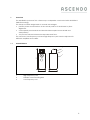
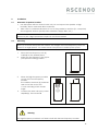
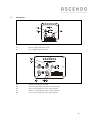
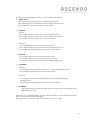
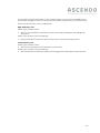
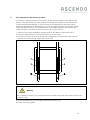
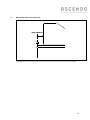
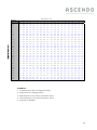
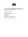
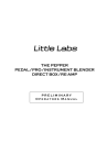
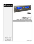
SYSTEM M-F2
USER'S MANUAL
Contents
1
OVERVIEW ........................................................................................................................... 3
1.1 Overall Picture .................................................................................................................. 3
1.2 Application ....................................................................................................................... 3
1.3 Safety Warning ................................................................................................................. 4
1.4 Operating modes ............................................................................................................ 4
1.5 Technical Data ................................................................................................................ 5
2
INSTALLATION...................................................................................................................... 6
2.1 Demands of speaker location ....................................................................................... 6
2.2 Mounting ........................................................................................................................... 6
3
TRANSPORT .......................................................................................................................... 7
4
CONNECTION ..................................................................................................................... 8
5
TIME ALIGNMENT FOR THE LISTENER'S POSITION ............................................................. 11
5.1 Adjustment of the Time alignment .............................................................................. 12
6
CLEANING ......................................................................................................................... 14
ASCENDO GMBH
HÖLDERLINWEG 6
73257 KÖNGEN
GERMANY
Phone:
Fax:
0049 (0) 7024 9288 84
0049 (0) 7024 9288 64
[email protected]
MAIL:
www.ascendo.de
2
1.
Overview
The ASCENDO System MF-2 is a three-way Loudspeaker constructed with ASCENDO's
SASB-Technology.
The strictly modular design leads to several advantages.
•
perfect phase reconstruction at the actual position of the listener by time
alignment.
•
consequently mechanical and electrical decoupled: more details and
transparency.
•
very low resonance between loudspeaker and floor.
The crossover, low-frequency-unit and high-frequency-unit can be adjusted for
different amplifiers and cables.
Overall Picture
1
2
3
1213
1.1
400
1
High frequency unit
2
Stainless steel mounting bars
3
Low frequency unit
450
3
1.2
Application
The ASCENDO Loudspeaker System MF-2 is intended for use in small to mid-size rooms
(< 150 m³, see section 2.1).
You can use the System M with amplifier in the power range of 10 W to 500 W.
1.3
Safety Warning
Warning
This Loudspeaker can produce big sound-levels. This may damage your ears
permanently!
1.4
Operating modes
You can use the System MF-2 in a single-amp setup (one power amplifier for high- and
low-frequency unit) or in a bi-amp setup (one power amplifier for the low-frequencyunit, one for the high-frequency unit) or in a tri-amp setup (one power amplifier for the
low-frequency-chassis, one for the middle-frequency chassis, one for the highfrequency unit).
If your setup is single-amping you must bridge the high- and low-frequency unit with a
high quality speaker cable.
4
1.5
Technical Data
Principle
Three-way SASB- technology
Construction
modular, low-resonance mounting of units
variable time-alignment for listener`s position between 50
cm and 190 cm over floor.
Material
Low-Magnetic Stainless-Steel
sandwich construction of Bitumen and MDF
Dimensions
40 / 121,3 / 45 cm
Weight
60 kg
Power
600 W RMS (min.)
Impedance
8 Ohm
Sensitivity
91 dB/1W/m
High-Frequency Unit
Driver: Ribbon Tweeter
Switch for high and low damping-factor of amp
Low-Frequency Unit
Outer Chassis:
21cm, HPS diaphragm,
phase plug
Inner Chassis:
28 cm, Hexacone diaphragm
Switch for high and low damping-factor of amp
Connector
Si / Bi / Tri-Wiring
Finish
Piano lacquer: black / white
5
2.
Installation
2.1
Demands of speaker location
•
Use the System MF-2 in closed rooms only. Do not expose the speaker to high
humidity, direct water and direct sunbeam.
•
Take care of a minimum distance of 2 m of the speaker to monitors (TV, computer)
and magnetic devices (audio/video-cassettes, floppy-disks, etc.).
WARNING
There may be a slight permanent imprint in soft floor-material!
2.2
Mounting
WARNING
Don’t try to mount the System MF-2 alone. The weight of the low-frequency unit is too
much for a single person. You need at least two persons to build up the system.
1.
Place the low-frequency unit (3)
carefully at the desired place.
2.
Adjust the low-frequency unit (3) for
your specific hearing position.
3.
Place the high-frequency module
on top of the low-frequency
module.
The stainless steel bars (2) shall start
and end at the end of the
12 mm rounding of the woofer
edge.
4.
Connect the units with your power
amplifier(s). See section 4
Warning
The high frequency module is not fixed or bolt with the low-frequency module.
6
3
Transport
Warning
Don’t try to move or transport the System MF-2alone! The weight affords at least
two persons.
1. Switch off the power amplifiers and disconnect all cables of the
System MF-2.
2. Pull off the high-frequency (1) unit from the low-frequency unit (3). Lay it on a soft
dry cloth. Take care not to touch the diaphragm of the tweeter.
3. Lift the low-frequency unit from the stand and the upper back-spike. Take care not
to touch the diaphragm of the woofer.
4. Place the low-frequency unit (3) at its new position.
7
4.
Connection
4.1
Switch / High-frequency-unit
5.1
Minus / High-frequency-unit
6.1
Plus / High-frequency-unit
4.2
Switch Low-frequency-unit
5.2
Minus / Low-frequency-unit / outer chassis
6.2
Plus / Low-frequency-unit / outer chassis
5.3
Minus / Low-frequency-unit / inner chassis
6.3
Plus / Low-frequency-unit / inner chassis
8
The high- and low-frequency unit can be connected as follows:
•
single-wired:
- one cable-pair from power-amp to high-frequency unit
- one cable-pair from low-frequency unit to high-frequency unit
- one cable-pair from inner chassis to outer chassis
•
bi-wired:
Version1:
- one cable pair from power amp to low-frequency unit
- one cable pair from the power amp to high-frequency unit
- one cable pair from inner chassis to outer chassis
Version2:
- one cable pair from power amp to inner chassis
- one cable pair from the power amp to high-frequency unit
- one cable pair from high-frequency-unit to outer chassis
•
tri-wired:
- one cable pair from power amp to outer chassis
- one cable pair from the power amp to inner chassis
- one cable pair from the power amp to high-frequency unit.
•
bi-amped:
Version1:
- one cable-pair from separate amps for low- and high-frequency unit
- one cable-pair from inner chassis to outer chassis
Version2:
- one cable-pair from two separate amps for inner chassis and highfrequency unit
- one cable-pair from high-frequency unit to outer chassis
•
tri-amped:
-
one cable-pair from three separate amps to inner chassis, outer chassis and
high-frequency unit.
Take care of connecting always the plus (red) terminal of your power amp with the
plus (6 / red) terminal of the speaker!
Take care not to connect a plus with a minus pin of your cable!
9
The speaker-units are adjustable to the characteristics of your power-amplifier. Since
these differ strongly you have to check the best switch position for your specific setup.
These are the key-rules for the adjustment:
High-frequency unit
Switch (4) in position VD-N
•
This is recommended for transistor power amps with damping-factor falling with
frequency
Switch (4) in position VD-H (Standard)
•
Recommended for transistor power amps with constant damping factor
Low-frequency unit
Switch (4) in position VD-N
•
This is recommended for fast transistor power amps.
Switch (4) in position VD-H (Standard)
•
Recommended for transistor amps with strongly load- dependent output-power
10
5.
Time alignment for the listener’s position
To achieve a perfect phase reconstruction, at the actual position of the listener, the
delays of the transducers must be adjusted carefully. The position of the tweeter has
to be mechanically adjusted, so that a plane wave will leave the speaker system
exactly in the direction to the listener's ear. This is possible owing to the specific design
of the ASCENDO Systems. The displacement of the high frequency Unit ensures the
correct phase in over-floor positions between 50 cm and 190 cm.
1. Switch off the power amplifiers and disconnect all cables of the System MF-2
2. Place the high frequency unit upside down on a soft towel.
3. Loose the 4 screws (7) that fix the steel mounting bars (2) at the unit. Take care not
to remove the screws fully. Apply 2-3 rounds only.
Warning
Don’t open the screws (7) too many rounds! The screw may loose the contact to the LowFrequency unit.
4. Move the steel bars (2) to the right position (see section 5.1).
5. Fix the screws (7) again.
11
5.1
Adjustment of the time alignment
The adjustment is measured from the front of the woofer to the front of the tweeter.
12
Distance in cm
Area Of
Adjustment 150 160
170 180
190 200
225 250 275 300
325 350
375 400
425 450 475 500
600
80,0
2,1
2,0
1,9
1,8
1,7
1,7
1,5
1,4
1,3
1,2
1,2
1,1
1,1
1,0
1,0
1,0
0,9
0,9
0,8
82,5
2,3
2,2
2,1
2,0
2,0
1,9
1,7
1,6
1,5
1,5
1,4
1,3
1,3
1,2
1,2
1,2
1,1
1,1
1,0
85,0
2,6
2,5
2,4
2,3
2,2
2,1
2,0
1,9
1,8
1,7
1,6
1,6
1,5
1,5
1,4
1,4
1,4
1,3
1,2
87,5
2,8
2,7
2,6
2,5
2,4
2,4
2,2
2,1
2,0
1,9
1,8
1,8
1,7
1,7
1,6
1,6
1,6
1,5
1,4
90,0
3,1
2,9
2,8
2,7
2,7
2,6
2,4
2,3
2,2
2,1
2,0
2,0
1,9
1,9
1,8
1,8
1,8
1,7
1,7
92,5
3,3
3,2
3,1
3,0
2,9
2,8
2,7
2,5
2,4
2,3
2,3
2,2
2,2
2,1
2,1
2,0
2,0
2,0
1,9
95,0
3,6
3,4
3,3
3,2
3,1
3,1
2,9
2,8
2,7
2,6
2,5
2,4
2,4
2,3
2,3
2,2
2,2
2,2
2,1
97,5
3,8
3,7
3,6
3,5
3,4
3,3
3,1
3,0
2,9
2,8
2,7
2,6
2,6
2,5
2,5
2,4
2,4
2,4
2,3
100,0
4,1
3,9
3,8
3,7
3,6
3,5
3,4
3,2
3,1
3,0
2,9
2,9
2,8
2,7
2,7
2,7
2,6
2,6
2,5
102,5
4,3
4,2
4,0
3,9
3,9
3,8
3,6
3,4
3,3
3,2
3,1
3,1
3,0
3,0
2,9
2,9
2,8
2,8
2,7
105,0
4,5
4,4
4,3
4,2
4,1
4,0
3,8
3,7
3,6
3,5
3,4
3,3
3,2
3,2
3,1
3,1
3,1
3,0
2,9
107,5
4,8
4,7
4,5
4,4
4,3
4,2
4,0
3,9
3,8
3,7
3,6
3,5
3,5
3,4
3,3
3,3
3,3
3,2
3,1
110,0
5,0
4,9
4,8
4,7
4,6
4,5
4,3
4,1
4,0
3,9
3,8
3,7
3,7
3,6
3,6
3,5
3,5
3,4
3,3
112,5
5,3
5,1
5,0
4,9
4,8
4,7
4,5
4,4
4,2
4,1
4,0
4,0
3,9
3,8
3,8
3,7
3,7
3,7
3,5
115,0
5,5
5,4
5,3
5,1
5,0
4,9
4,7
4,6
4,5
4,3
4,3
4,2
4,1
4,0
4,0
3,9
3,9
3,9
3,7
117,5
5,8
5,6
5,5
5,4
5,3
5,2
5,0
4,8
4,7
4,6
4,5
4,4
4,3
4,3
4,2
4,2
4,1
4,1
4,0
120,0
6,0
5,9
5,7
5,6
5,5
5,4
5,2
5,0
4,9
4,8
4,7
4,6
4,5
4,5
4,4
4,4
4,3
4,3
4,2
122,5
6,3
6,1
6,0
5,9
5,7
5,6
5,4
5,3
5,1
5,0
4,9
4,8
4,8
4,7
4,6
4,6
4,5
4,5
4,4
125,0
6,5
6,4
6,2
6,1
6,0
5,9
5,7
5,5
5,3
5,2
5,1
5,0
5,0
4,9
4,8
4,8
4,8
4,7
4,6
127,5
6,8
6,6
6,5
6,3
6,2
6,1
5,9
5,7
5,6
5,5
5,4
5,3
5,2
5,1
5,1
5,0
5,0
4,9
4,8
130,0
7,0
6,9
6,7
6,6
6,5
6,4
6,1
5,9
5,8
5,7
5,6
5,5
5,4
5,3
5,3
5,2
5,2
5,1
5,0
132,5
7,3
7,1
7,0
6,8
6,7
6,6
6,4
6,2
6,0
5,9
5,8
5,7
5,6
5,6
5,5
5,4
5,4
5,3
5,2
135,0
7,5
7,3
7,2
7,1
6,9
6,8
6,6
6,4
6,2
6,1
6,0
5,9
5,8
5,8
5,7
5,7
5,6
5,6
5,4
137,5
7,8
7,6
7,4
7,3
7,2
7,1
6,8
6,6
6,5
6,3
6,2
6,1
6,1
6,0
5,9
5,9
5,8
5,8
5,6
140,0
8,0
7,8
7,7
7,5
7,4
7,3
7,0
6,9
6,7
6,6
6,5
6,4
6,3
6,2
6,1
6,1
6,0
6,0
5,8
142,5
8,3
8,1
7,9
7,8
7,6
7,5
7,3
7,1
6,9
6,8
6,7
6,6
6,5
6,4
6,3
6,3
6,2
6,2
6,0
145,0
8,5
8,3
8,2
8,0
7,9
7,8
7,5
7,3
7,1
7,0
6,9
6,8
6,7
6,6
6,6
6,5
6,5
6,4
6,3
147,5
8,8
8,6
8,4
8,3
8,1
8,0
7,7
7,5
7,4
7,2
7,1
7,0
6,9
6,8
6,8
6,7
6,7
6,6
6,5
150,0
9,0
8,8
8,6
8,5
8,4
8,2
8,0
7,8
8,7
8,5
8,4
8,3
8,2
8,1
7,0
6,9
6,9
6,8
6,7
Conditions:
1. Coplanar setup (left and right speaker)
2 Adjustment to hearing position
3. High-frequency unit switch in position“VD-H”
4. Low-frequency unit switch in position “VD-H”
5. 0-phasis of amplifier
13
6.
Cleaning
Clean the enclosure and stand of the ASCENDO System MF-2 with a dry and soft
cloth.
Don’t use water or other chemicals. Don’t touch the tweeter and the woofer.
14