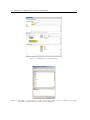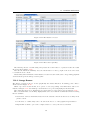
1
oper
a
J
Process Support for Web Services
The JOpera Manual
v2.4.3 March 1st 2009
http://www.jopera.org
[email protected]
(C)1999-2009 Cesare Pautasso
ii
Contents
1 Introduction
1.1 What is JOpera for Eclipse? . . . .
1.2 What’s new in JOpera for Eclipse?
1.3 About JOpera for Eclipse . . . . .
1.4 About this manual . . . . . . . . .
1.5 Revision . . . . . . . . . . . . . . .
.
.
.
.
.
.
.
.
.
.
.
.
.
.
.
.
.
.
.
.
.
.
.
.
.
.
.
.
.
.
.
.
.
.
.
.
.
.
.
.
.
.
.
.
.
.
.
.
.
.
.
.
.
.
.
.
.
.
.
.
.
.
.
.
.
.
.
.
.
.
.
.
.
.
.
.
.
.
.
.
.
.
.
.
.
.
.
.
.
.
.
.
.
.
.
.
.
.
.
.
.
.
.
.
.
.
.
.
.
.
.
.
.
.
.
.
.
.
.
.
.
.
.
.
.
1
1
1
2
2
3
2 Getting Started
2.1 Installation . . . . . . . . . . . . . . . . . .
2.1.1 System Requirements . . . . . . . .
2.2 Running JOpera for Eclipse . . . . . . . . .
2.3 Upgrade . . . . . . . . . . . . . . . . . . . .
2.4 Basics . . . . . . . . . . . . . . . . . . . . .
2.4.1 Service Composition with Processes
2.4.2 Design-Time User Interface . . . . .
2.4.3 Compiling Processes . . . . . . . . .
2.4.4 Deploying Processes . . . . . . . . .
2.4.5 Running Processes . . . . . . . . . .
2.4.6 Monitoring Processes . . . . . . . . .
2.5 Examples . . . . . . . . . . . . . . . . . . .
.
.
.
.
.
.
.
.
.
.
.
.
.
.
.
.
.
.
.
.
.
.
.
.
.
.
.
.
.
.
.
.
.
.
.
.
.
.
.
.
.
.
.
.
.
.
.
.
.
.
.
.
.
.
.
.
.
.
.
.
.
.
.
.
.
.
.
.
.
.
.
.
.
.
.
.
.
.
.
.
.
.
.
.
.
.
.
.
.
.
.
.
.
.
.
.
.
.
.
.
.
.
.
.
.
.
.
.
.
.
.
.
.
.
.
.
.
.
.
.
.
.
.
.
.
.
.
.
.
.
.
.
.
.
.
.
.
.
.
.
.
.
.
.
.
.
.
.
.
.
.
.
.
.
.
.
.
.
.
.
.
.
.
.
.
.
.
.
.
.
.
.
.
.
.
.
.
.
.
.
.
.
.
.
.
.
.
.
.
.
.
.
.
.
.
.
.
.
.
.
.
.
.
.
.
.
.
.
.
.
.
.
.
.
.
.
.
.
.
.
.
.
.
.
.
.
.
.
.
.
.
.
.
.
.
.
.
.
.
.
.
.
.
.
.
.
.
.
.
.
.
.
.
.
.
.
.
.
.
.
.
.
.
.
.
.
.
.
.
.
.
.
.
.
.
.
.
.
.
.
.
.
.
.
.
.
.
.
5
5
6
6
7
7
7
7
9
10
10
11
13
I
.
.
.
.
.
.
.
.
.
.
.
.
.
.
.
.
.
.
.
.
Tutorials
15
3 Hello World Tutorial
3.1 Creating a new Project . . . . . . . . . .
3.2 Creating a new OML file . . . . . . . . . .
3.3 Setting up the Hallo World Program . . .
3.4 Running the Program with a test Process
3.5 Checking the Results . . . . . . . . . . . .
.
.
.
.
.
.
.
.
.
.
.
.
.
.
.
.
.
.
.
.
.
.
.
.
.
.
.
.
.
.
.
.
.
.
.
.
.
.
.
.
.
.
.
.
.
.
.
.
.
.
.
.
.
.
.
.
.
.
.
.
.
.
.
.
.
.
.
.
.
.
.
.
.
.
.
.
.
.
.
.
.
.
.
.
.
.
.
.
.
.
.
.
.
.
.
.
.
.
.
.
.
.
.
.
.
.
.
.
.
.
.
.
.
.
.
.
.
.
.
.
.
.
.
.
.
17
17
17
18
21
22
4 Web Services Tutorial
4.1 Web Services Tutorial Overview . . . .
4.2 Creating a new Project . . . . . . . .
4.3 Importing a WSDL File . . . . . . . .
4.4 Creating a new Process . . . . . . . .
4.5 Adding Input/Output Parameters . .
4.6 Populating the Process . . . . . . . . .
4.7 Draw Data Flow Connections . . . . .
4.8 Compilation of the Process . . . . . .
4.9 Executing and Monitoring the Process
.
.
.
.
.
.
.
.
.
.
.
.
.
.
.
.
.
.
.
.
.
.
.
.
.
.
.
.
.
.
.
.
.
.
.
.
.
.
.
.
.
.
.
.
.
.
.
.
.
.
.
.
.
.
.
.
.
.
.
.
.
.
.
.
.
.
.
.
.
.
.
.
.
.
.
.
.
.
.
.
.
.
.
.
.
.
.
.
.
.
.
.
.
.
.
.
.
.
.
.
.
.
.
.
.
.
.
.
.
.
.
.
.
.
.
.
.
.
.
.
.
.
.
.
.
.
.
.
.
.
.
.
.
.
.
.
.
.
.
.
.
.
.
.
.
.
.
.
.
.
.
.
.
.
.
.
.
.
.
.
.
.
.
.
.
.
.
.
.
.
.
.
.
.
.
.
.
.
.
.
.
.
.
.
.
.
.
.
.
.
.
.
.
.
.
.
.
.
.
.
.
.
.
.
.
.
.
.
.
.
.
.
.
.
.
.
.
.
.
.
.
.
.
.
.
23
23
23
23
24
24
25
25
25
25
5 Monitoring Widget Tutorial
5.1 Introduction . . . . . . . . . . . . . . . . . . . . . . . . . . . . . . . . . . . . . . . . . .
5.2 Adding a Monitoring Widget . . . . . . . . . . . . . . . . . . . . . . . . . . . . . . . .
5.3 Example . . . . . . . . . . . . . . . . . . . . . . . . . . . . . . . . . . . . . . . . . . . .
31
31
31
32
.
.
.
.
.
.
.
.
.
.
.
.
.
.
.
.
.
.
iii
Contents
5.4
TaskDisplayer API . . . . . . . . . . . . . . . . . . . . . . . . . . . . . . . . . . . . . .
6 Java Services Tutorial
6.1 Java Snippets . . . . . . . . . . . . . . . . .
6.1.1 Calling Java Snippets from a JOpera
6.1.2 Testing the Java snippet . . . . . . .
6.2 Java Methods . . . . . . . . . . . . . . . . .
6.2.1 Importing Java Classes . . . . . . .
6.2.2 Calling Java Static Methods . . . . .
6.3 Java Objects . . . . . . . . . . . . . . . . .
6.3.1 Working with Objects as parameters
. . . . . .
Program
. . . . . .
. . . . . .
. . . . . .
. . . . . .
. . . . . .
. . . . . .
.
.
.
.
.
.
.
.
.
.
.
.
.
.
.
.
.
.
.
.
.
.
.
.
.
.
.
.
.
.
.
.
.
.
.
.
.
.
.
.
.
.
.
.
.
.
.
.
.
.
.
.
.
.
.
.
.
.
.
.
.
.
.
.
.
.
.
.
.
.
.
.
.
.
.
.
.
.
.
.
.
.
.
.
.
.
.
.
.
.
.
.
.
.
.
.
.
.
.
.
.
.
.
.
.
.
.
.
.
.
.
.
.
.
.
.
.
.
.
.
.
.
.
.
.
.
.
.
.
.
.
.
.
.
.
.
.
.
.
.
.
.
.
.
II Reference Manual
33
35
35
35
35
36
36
36
36
36
39
7 Frequently Asked Questions
7.1 General Questions . . . . . . . . . . . . . . . . .
7.2 Questions about Developing Processes . . . . . .
7.3 Questions about Running Processes . . . . . . .
7.4 Questions about Integrating Processes with other
7.5 Running JOpera as a server . . . . . . . . . . . .
7.6 Other questions . . . . . . . . . . . . . . . . . . .
7.7 Troubleshooting . . . . . . . . . . . . . . . . . . .
. . . . . . .
. . . . . . .
. . . . . . .
applications
. . . . . . .
. . . . . . .
. . . . . . .
.
.
.
.
.
.
.
.
.
.
.
.
.
.
.
.
.
.
.
.
.
.
.
.
.
.
.
.
.
.
.
.
.
.
.
.
.
.
.
.
.
.
.
.
.
.
.
.
.
.
.
.
.
.
.
.
.
.
.
.
.
.
.
.
.
.
.
.
.
.
.
.
.
.
.
.
.
.
.
.
.
.
.
.
.
.
.
.
.
.
.
.
.
.
.
.
.
.
41
41
41
43
44
45
45
46
8 How To...
8.1 How to
8.2 How to
8.3 How to
8.4 How to
publish a process as a Web service . .
debug a failed task . . . . . . . . . .
display a parameter in a web browser
Report a Bug . . . . . . . . . . . . .
.
.
.
.
.
.
.
.
.
.
.
.
.
.
.
.
.
.
.
.
.
.
.
.
.
.
.
.
.
.
.
.
.
.
.
.
.
.
.
.
.
.
.
.
.
.
.
.
.
.
.
.
.
.
.
.
.
.
.
.
.
.
.
.
.
.
.
.
.
.
.
.
.
.
.
.
.
.
.
.
.
.
.
.
.
.
.
.
.
.
.
.
49
49
49
50
51
9 JOpera Visual Composition Language Reference
9.1 Basic Patterns . . . . . . . . . . . . . . . . .
9.1.1 Empty Process . . . . . . . . . . . . .
9.1.2 Sequential . . . . . . . . . . . . . . . .
9.1.3 Parallel . . . . . . . . . . . . . . . . .
9.1.4 Flow . . . . . . . . . . . . . . . . . . .
9.2 Branching Control Flow Patterns . . . . . . .
9.2.1 Parallel Split . . . . . . . . . . . . . .
9.2.2 Synchronization . . . . . . . . . . . .
9.2.3 Simple Merge . . . . . . . . . . . . . .
9.2.4 Exclusive Choice . . . . . . . . . . . .
9.2.5 Multiple Choice . . . . . . . . . . . . .
9.2.6 Synchronizing Merge . . . . . . . . . .
9.2.7 Multiple Merge . . . . . . . . . . . . .
9.2.8 N out of M Join . . . . . . . . . . . .
9.3 Loops . . . . . . . . . . . . . . . . . . . . . .
9.3.1 Infinite loop . . . . . . . . . . . . . . .
9.3.2 While loop . . . . . . . . . . . . . . .
9.3.3 Arbitrary loop . . . . . . . . . . . . .
9.3.4 For-each loop . . . . . . . . . . . . . .
9.4 Data Flow Patterns . . . . . . . . . . . . . .
9.4.1 Discriminator . . . . . . . . . . . . . .
9.4.2 Shared State . . . . . . . . . . . . . .
9.4.3 Global State . . . . . . . . . . . . . .
.
.
.
.
.
.
.
.
.
.
.
.
.
.
.
.
.
.
.
.
.
.
.
.
.
.
.
.
.
.
.
.
.
.
.
.
.
.
.
.
.
.
.
.
.
.
.
.
.
.
.
.
.
.
.
.
.
.
.
.
.
.
.
.
.
.
.
.
.
.
.
.
.
.
.
.
.
.
.
.
.
.
.
.
.
.
.
.
.
.
.
.
.
.
.
.
.
.
.
.
.
.
.
.
.
.
.
.
.
.
.
.
.
.
.
.
.
.
.
.
.
.
.
.
.
.
.
.
.
.
.
.
.
.
.
.
.
.
.
.
.
.
.
.
.
.
.
.
.
.
.
.
.
.
.
.
.
.
.
.
.
.
.
.
.
.
.
.
.
.
.
.
.
.
.
.
.
.
.
.
.
.
.
.
.
.
.
.
.
.
.
.
.
.
.
.
.
.
.
.
.
.
.
.
.
.
.
.
.
.
.
.
.
.
.
.
.
.
.
.
.
.
.
.
.
.
.
.
.
.
.
.
.
.
.
.
.
.
.
.
.
.
.
.
.
.
.
.
.
.
.
.
.
.
.
.
.
.
.
.
.
.
.
.
.
.
.
.
.
.
.
.
.
.
.
.
.
.
.
.
.
.
.
.
.
.
.
.
.
.
.
.
.
.
.
.
.
.
.
.
.
.
.
.
.
.
.
.
.
.
.
.
.
.
.
.
.
.
.
.
.
.
.
.
.
.
.
.
.
.
.
.
.
.
.
.
.
.
.
.
.
.
.
.
.
.
.
.
.
.
.
.
.
.
.
.
.
.
.
.
.
.
.
.
.
.
.
.
.
.
.
.
.
.
.
.
.
.
.
.
.
.
.
.
.
.
.
.
.
.
.
.
.
.
.
.
.
.
.
.
.
.
.
.
.
.
.
.
.
.
.
.
.
.
.
.
.
.
.
.
.
.
.
.
.
.
.
.
.
.
.
.
.
.
.
.
.
.
.
.
.
.
.
.
.
.
.
.
.
.
.
.
.
.
.
.
.
.
.
.
.
.
.
.
.
.
.
.
.
.
.
.
.
.
.
.
.
.
.
.
.
.
.
.
.
.
.
.
.
.
.
.
.
.
.
.
.
.
.
.
.
.
.
.
.
.
.
.
.
.
.
.
.
.
.
.
.
.
.
.
.
.
.
.
.
.
.
.
.
53
53
53
53
53
54
54
54
54
55
55
55
55
55
55
55
55
56
57
57
58
58
58
58
iv
Contents
.
.
.
.
.
.
.
.
.
.
.
.
.
.
.
.
.
.
.
.
.
.
.
.
.
.
.
.
.
.
.
.
.
.
.
.
.
.
.
.
.
.
.
.
.
.
.
.
.
.
.
.
.
.
.
.
.
.
.
.
.
.
.
.
.
.
.
.
.
.
.
.
.
.
.
.
.
.
.
.
.
.
.
.
.
.
.
.
.
.
.
.
.
.
.
.
.
.
.
.
.
.
.
.
.
.
.
.
.
.
.
.
.
.
.
.
.
.
.
.
.
.
.
.
.
.
.
.
.
.
.
.
.
.
.
.
.
.
.
.
.
.
.
.
58
58
58
58
58
58
58
58
10 Feature Reference
10.1 WSDL Import Wizard . . . . . . . . . . . . .
10.1.1 The WSDL File and import Options .
10.1.2 Selecting the Operations . . . . . . . .
10.1.3 Warnings, Errors and Interpretations .
10.1.4 Known Limitations . . . . . . . . . . .
10.2 Autoconnection . . . . . . . . . . . . . . . . .
10.3 Refactoring . . . . . . . . . . . . . . . . . . .
10.3.1 Upgrade/replacement of programs and
10.3.2 Extract sub-process . . . . . . . . . .
10.3.3 Inline sub-process . . . . . . . . . . .
10.4 JOpera Kernel Command Line Reference . .
10.4.1 Starting processes . . . . . . . . . . .
10.4.2 Deleting process instances . . . . . . .
10.4.3 Listing deployed process templates . .
10.4.4 Undeploying process templates . . . .
. . . . . .
. . . . . .
. . . . . .
. . . . . .
. . . . . .
. . . . . .
. . . . . .
processes
. . . . . .
. . . . . .
. . . . . .
. . . . . .
. . . . . .
. . . . . .
. . . . . .
.
.
.
.
.
.
.
.
.
.
.
.
.
.
.
.
.
.
.
.
.
.
.
.
.
.
.
.
.
.
.
.
.
.
.
.
.
.
.
.
.
.
.
.
.
.
.
.
.
.
.
.
.
.
.
.
.
.
.
.
.
.
.
.
.
.
.
.
.
.
.
.
.
.
.
.
.
.
.
.
.
.
.
.
.
.
.
.
.
.
.
.
.
.
.
.
.
.
.
.
.
.
.
.
.
.
.
.
.
.
.
.
.
.
.
.
.
.
.
.
.
.
.
.
.
.
.
.
.
.
.
.
.
.
.
.
.
.
.
.
.
.
.
.
.
.
.
.
.
.
.
.
.
.
.
.
.
.
.
.
.
.
.
.
.
.
.
.
.
.
.
.
.
.
.
.
.
.
.
.
.
.
.
.
.
.
.
.
.
.
.
.
.
.
.
.
.
.
.
.
.
.
.
.
.
.
.
.
.
.
.
.
.
.
.
.
.
.
.
.
.
.
.
.
.
.
.
.
.
.
.
.
.
.
.
.
.
.
.
.
.
.
.
.
.
.
.
.
.
.
.
.
.
.
.
59
59
59
60
61
61
63
64
64
64
64
72
72
72
72
73
11 Lineage Tracking
11.1 Versioning . . . . . . . . . .
11.1.1 Introduction . . . .
11.1.2 Use . . . . . . . . .
11.2 database setup . . . . . . .
11.3 Memoization . . . . . . . .
11.3.1 Introduction . . . .
11.3.2 Use of Memoization
11.4 Lineage Tracking . . . . . .
11.4.1 Introduction . . . .
11.4.2 Lineage Summary .
11.4.3 Instance Browser . .
11.4.4 Lineage Browser . .
11.4.5 Property Panel . . .
.
.
.
.
.
.
.
.
.
.
.
.
.
.
.
.
.
.
.
.
.
.
.
.
.
.
.
.
.
.
.
.
.
.
.
.
.
.
.
.
.
.
.
.
.
.
.
.
.
.
.
.
.
.
.
.
.
.
.
.
.
.
.
.
.
.
.
.
.
.
.
.
.
.
.
.
.
.
.
.
.
.
.
.
.
.
.
.
.
.
.
.
.
.
.
.
.
.
.
.
.
.
.
.
.
.
.
.
.
.
.
.
.
.
.
.
.
.
.
.
.
.
.
.
.
.
.
.
.
.
.
.
.
.
.
.
.
.
.
.
.
.
.
.
.
.
.
.
.
.
.
.
.
.
.
.
.
.
.
.
.
.
.
.
.
.
.
.
.
.
.
.
.
.
.
.
.
.
.
.
.
.
.
.
.
.
.
.
.
.
.
.
.
.
.
.
.
.
.
.
.
.
.
.
.
.
.
.
.
.
.
.
.
.
.
.
.
.
.
.
.
.
.
.
.
.
.
.
.
.
.
.
.
.
75
75
75
75
76
76
76
77
78
78
79
79
80
81
9.5
9.4.4 Persistent Data . . . . . . . . . . . . . .
9.4.5 Generic Data Transformation . . . . . .
Advanced Patterns . . . . . . . . . . . . . . . .
9.5.1 Recursion . . . . . . . . . . . . . . . . .
9.5.2 Timeout . . . . . . . . . . . . . . . . . .
9.5.3 Dynamic Late Binding . . . . . . . . . .
9.5.4 Asynchronous Cancellation . . . . . . .
9.5.5 Synchronous to asynchronous Mapping .
.
.
.
.
.
.
.
.
.
.
.
.
.
.
.
.
.
.
.
.
.
.
.
.
.
.
.
.
.
.
.
.
.
.
.
.
.
.
.
.
.
.
.
.
.
.
.
.
.
.
.
.
.
.
.
.
.
.
.
.
.
.
.
.
.
.
.
.
.
.
.
.
.
.
.
.
.
.
.
.
.
.
.
.
.
.
.
.
.
.
.
.
.
.
.
.
.
.
.
.
.
.
.
.
.
.
.
.
.
.
.
.
.
.
.
.
.
.
.
.
.
.
.
.
.
.
.
.
.
.
.
.
.
.
.
.
.
.
.
.
.
.
.
.
.
.
.
.
.
.
.
.
.
.
.
.
.
.
.
.
.
.
.
.
.
.
.
.
.
.
.
.
.
.
.
.
.
.
.
.
.
.
.
.
.
.
.
.
.
.
.
.
.
.
.
.
.
.
.
.
.
.
.
.
.
.
.
.
.
.
.
.
.
.
.
.
.
.
.
.
.
.
.
.
.
.
.
III Developer Reference
83
12 How to write Service Invocation Plugins
12.1 Adapter Metaphor . . . . . . . . . . . . . . . . . . . . . . .
12.2 Example service invocation plugin . . . . . . . . . . . . . .
12.3 Setting up a new service invocation plugin . . . . . . . . . .
12.4 Identifying Component Types . . . . . . . . . . . . . . . . .
12.5 The OML Component Type Definition . . . . . . . . . . . .
12.5.1 Defining System Parameters . . . . . . . . . . . . . .
12.5.2 Editing System Parameters with the Adapter Editor
12.5.3 System Parameter Types . . . . . . . . . . . . . . .
v
.
.
.
.
.
.
.
.
.
.
.
.
.
.
.
.
.
.
.
.
.
.
.
.
.
.
.
.
.
.
.
.
.
.
.
.
.
.
.
.
.
.
.
.
.
.
.
.
.
.
.
.
.
.
.
.
.
.
.
.
.
.
.
.
.
.
.
.
.
.
.
.
.
.
.
.
.
.
.
.
.
.
.
.
.
.
.
.
.
.
.
.
.
.
.
.
.
.
.
.
.
.
.
.
.
.
.
.
.
.
.
.
.
.
.
.
.
.
.
.
85
85
85
85
86
87
87
88
88
Contents
12.6 The ISubSystem Interface . . . . . . . . . . . . . . . .
12.7 The IJob Interface . . . . . . . . . . . . . . . . . . . .
12.8 Control flow mapping . . . . . . . . . . . . . . . . . .
12.8.1 Synchronous Service Invocation . . . . . . . . .
12.8.2 Asynchronous Service Invocation . . . . . . . .
12.9 Failure detection . . . . . . . . . . . . . . . . . . . . .
12.10Data flow mapping . . . . . . . . . . . . . . . . . . . .
12.11Threading model . . . . . . . . . . . . . . . . . . . . .
12.12Example Code for Synchronous invocation . . . . . . .
12.13Example Code for Asynchronous invocation . . . . . .
12.14Example Code for partial result notification . . . . . .
12.15Example Code for progress notification . . . . . . . . .
12.16Example Code for safe streaming intermediate output
12.17Example Code for the Signal Method . . . . . . . . . .
.
.
.
.
.
.
.
.
.
.
.
.
.
.
.
.
.
.
.
.
.
.
.
.
.
.
.
.
.
.
.
.
.
.
.
.
.
.
.
.
.
.
.
.
.
.
.
.
.
.
.
.
.
.
.
.
.
.
.
.
.
.
.
.
.
.
.
.
.
.
.
.
.
.
.
.
.
.
.
.
.
.
.
.
.
.
.
.
.
.
.
.
.
.
.
.
.
.
.
.
.
.
.
.
.
.
.
.
.
.
.
.
.
.
.
.
.
.
.
.
.
.
.
.
.
.
.
.
.
.
.
.
.
.
.
.
.
.
.
.
.
.
.
.
.
.
.
.
.
.
.
.
.
.
.
.
.
.
.
.
.
.
.
.
.
.
.
.
.
.
.
.
.
.
.
.
.
.
.
.
.
.
.
.
.
.
.
.
.
.
.
.
.
.
.
.
.
.
.
.
.
.
.
.
.
.
.
.
.
.
.
.
.
.
.
.
.
.
.
.
.
.
.
.
.
.
.
.
.
.
.
.
.
.
.
.
.
.
.
.
.
.
.
.
.
.
.
.
.
.
.
.
89
90
91
91
91
91
92
92
92
93
94
94
94
94
.
.
.
.
.
.
.
.
.
.
.
.
.
.
.
.
.
.
.
.
.
.
.
.
.
.
.
.
.
.
.
.
.
.
.
.
.
.
.
.
.
.
.
.
.
.
.
.
.
.
.
.
.
.
.
.
.
.
.
.
.
.
.
.
.
.
.
.
.
.
.
.
.
.
.
.
.
.
.
.
.
.
.
.
.
.
.
.
.
.
.
.
.
.
.
.
.
.
.
.
.
.
.
.
.
.
.
.
.
.
.
.
.
.
.
.
.
.
.
.
.
.
.
.
.
.
.
.
.
.
.
.
.
.
.
.
.
.
.
.
.
.
.
.
.
.
.
.
.
.
.
.
.
.
.
.
.
.
.
.
.
.
.
.
.
.
.
.
.
.
.
.
.
.
.
.
.
.
.
.
.
.
.
.
.
.
.
.
.
.
.
.
.
.
.
.
.
.
.
.
.
.
.
.
.
.
.
.
.
.
.
.
.
.
.
.
.
.
.
.
.
.
.
.
.
.
.
.
.
.
.
.
.
.
.
.
.
.
.
.
.
.
.
.
.
.
.
.
.
.
.
.
.
.
.
.
.
.
.
.
.
.
.
.
.
.
.
.
.
.
.
.
.
.
.
.
.
.
.
.
.
.
.
.
.
.
.
.
.
.
.
.
.
.
.
.
.
.
.
.
.
.
.
.
.
.
95
96
97
97
97
97
97
97
97
97
98
98
98
98
98
98
98
98
14 How to write Documentation
14.1 Setup . . . . . . . . . . . . . . . . . . . . . . . . . . . . . . . . . . . . . . . . . . . . .
14.2 XML Reference . . . . . . . . . . . . . . . . . . . . . . . . . . . . . . . . . . . . . . . .
99
99
99
13 Component Type Reference
13.1 Overview . . . . . . . . . . . . . . . .
13.2 Asynchronous SOAP Message Routing
13.3 Asynchronous Local Messaging . . . .
13.4 BPEL snippets . . . . . . . . . . . . .
13.5 Condor Job Submission . . . . . . . .
13.6 JOpera ECHO . . . . . . . . . . . . .
13.7 JOpera Delayed ECHO . . . . . . . .
13.8 HTTP/URL Download . . . . . . . . .
13.9 Java method invocation . . . . . . . .
13.10Java snippets . . . . . . . . . . . . . .
13.11Parameter Viewer . . . . . . . . . . .
13.12SQL/JDBC . . . . . . . . . . . . . . .
13.13Secure Shell Operation . . . . . . . . .
13.14Synchronous SOAP Messaging . . . .
13.15UNIX Legacy Applications . . . . . .
13.16XML transformations . . . . . . . . .
13.17Web Services Invocation Framework .
.
.
.
.
.
.
.
.
.
.
.
.
.
.
.
.
.
.
.
.
.
.
.
.
.
.
.
.
.
.
.
.
.
.
vi
.
.
.
.
.
.
.
.
.
.
.
.
.
.
.
.
.
.
.
.
.
.
.
.
.
.
.
.
.
.
.
.
.
.
.
.
.
.
.
.
.
.
.
.
.
.
.
.
.
.
.
.
.
.
.
.
.
.
.
.
.
.
.
.
.
.
.
.
.
.
.
.
.
.
.
.
.
.
.
.
.
.
.
.
.
.
.
.
.
.
.
.
.
.
.
.
.
.
.
.
.
.
.
.
.
.
.
.
.
.
.
.
.
.
.
.
.
.
.
1 Introduction
Welcome to JOpera: Process Support for more than Web Services. With this system you can rapidly
build processes which interconnect many different types of software components, including but not
limited to Web Services.
1.1 What is JOpera for Eclipse?
JOpera targets developers of Service-Oriented Business Applications and provides them with tools
for rapid service composition. It includes a visual modeling environment, a light-weight execution
engine, and also powerful debugging/refactoring tools which natively support the iterative nature of
service composition. Service composition models in JOpera are defined at a higher level of abstraction
than traditional BPM/BPEL languages and cover both architectural (structural) aspects as well as
behavioural (flow) ones. JOpera is built as a collection of plugins for Eclipse, thus having great
potential for further extensibility and integration with other SOA tools.
1.2 What’s new in JOpera for Eclipse?
JOpera for Eclipse is a complete rewrite of JOpera for Windows as a set of Eclipse plugins. It not just
a port of JOpera to run on Windows, Linux and Mac, but also a significant improvement, adding a
lot of new functionality. Here are some examples:
• Support for editing multiple source files
• Support for editing different versions of the same process
• Automatic background model checking: errors and warnings are listed in the problem view as
you work
• Automatic incremental recompilation and transparent redeployment of processes
• The JOpera process execution kernel is embedded into the Eclipse workbench and is started
automatically
• A fully fledged application server is also embedded so that processes can be published as Web
services with one mouse click (Section 8.1 on page 49)
• You can add your own service invocation adapters and package them as Eclipse plugins. In
addition to Web services (through SOAP/HTTP and WSIF), plugins are available to efficiently
invoke Java snippets, Java classes, remote UNIX commands through SSH, XML transformations
(XSLT, XPATH), SQL queries sent to any JDBC database, large Job submissions to clusters
managed by Condor.
• Examples can be added to the workspace using the New > Examples... menu command of Eclipse.
(Section 2.5 on page 13)
• You can more easily build your own program library and also reuse the standard library of
programs that come with JOpera
• JOpera for Eclipse is agile: it now includes visual refactoring and regression testing tools
1
1. INTRODUCTION
• JOpera for Eclipse integrates with the rest of the tools that run on the platform (e.g., CVS,
WTP, TPTP)
JOpera for Eclipse is backwards compatible with JOpera for Windows (v1.71 and below). However,
JOpera 1.71 is not upwards compatible with JOpera for Eclipse.
1.3 About JOpera for Eclipse
Web services offer a standards-based approach to address many interoperability issues arising when
composing distributed software systems out of reusable services. Thanks to the SOAP protocol
and WSDL interface description language, an increasingly large number of basic services are being
published on the Internet. Clearly, it becomes important to find the right composition abstractions
in order to build value added services out of the aggregation of basic ones. Complementing existing
approaches based on the XML syntax (e.g., BPML, BPEL) we have designed a visual syntax for
a service composition language. Thus, the data exchanges between the services (data flow), their
order of invocation and the necessary failure handling behavior (control flow) can be all specified
with a simple, graph-based, visual syntax. As opposed to an XML based approach, a visual language
can greatly enhance the understandability of the composite system and provide the foundation for
building rapid service composition tools, such as the JOpera for Eclipse system.
Among nesting, recursion, iteration, and reflection constructs, a very important feature of the
JOpera Visual Composition Language consists of describing how to compose services at the level of
abstraction represented by their interfaces. Thus, the description on how to compose the services
is independent of the actual low-level protocols and mechanisms that are used to perform the
actual service invocation. Abstracting the interface of a service from its access mechanism helps
to generalize the scope of the JOpera composition language and system well beyond Web services.
This way, the user can freely choose to compose the most appropriate kind of services in terms of
performance, reliability, security and convenience. Likewise, the composition language is not affected
when extending the underlying system to support other kinds of services. In other words, JOpera is
future-proof and can readily support future revisions of today’s Web services standards.
Thanks to this flexible approach, it is possible to unify composition and mediation aspects within
the same language. In a typical service composition scenario, Web services published by independent
organizations are to be composed in a bottom-up fashion. In general, a mismatch between these
services it is to be expected. With JOpera, in order to solve the problems due to different data
representations or incompatible interaction styles, a service fulfilling the role of mediator can be
added in a straightforward manner. Furthermore, such mediator can be implemented with the most
suitable technology, e.g., an XSLT transformation or a Java snippet.
For execution, the JOpera Visual Composition Language is compiled to Java code. To ensure the
required level of scalability, reliability and flexibility, such code is dynamically loaded into a runtime
container: the JOpera kernel. The flexible architecture of the JOpera kernel can be deployed in different
configurations: stand-alone, embedded into other systems (e.g., application servers or development
tools like Eclipse). The same architecture can also be replicated across a cluster of computers to
handle the concurrent execution of a large number of composite services. The JOpera distributed
kernel can also monitor its internal behaviour and configure itself automatically in order to provide
an optimal balance between providing good performance and efficiently using the available resources.
1.4 About this manual
This manual contains basic information on how to work with JOpera, including several step by step
tutorials with many screenshots and a reference to the most important commands and configura-
2
1.5. REVISION
tion options. Comments and contributions on how to improve the manual and JOpera are welcome
([email protected]).
Note: Given the rate at which the system’s user interface changes, it is not always possible to keep
the screenshots of the documentation consistent with the latest version of the actual software.
1.5 Revision
$Id: jop.xml 5495 2008-12-17 14:29:22Z cp $
3
1. INTRODUCTION
4
2 Getting Started
.
2.1 Installation
Installing JOpera for Eclipse is done in a few steps:
1. Start Eclipse.
Note: If you do not already have an installation of Eclipse 3.3 or 3.4, download it from http:
//www.eclipse.org , unzip it, and start it.
2. Select the Help Menu and click on Software Updates and then on Find and Install... Select
Search for new features to install and push the Next button.
Figure 2.1: Help, Software Updates, Find and Install...
3. Push the New Remote Site... button on the top right. Enter JOpera as name and http://www.
update.jopera.org/ as URL and hit the Ok button.
Figure 2.2: Adding the JOpera Update Site
5
2. GETTING STARTED
Then check/select the box of the newly created JOpera site as well as of the Eclipse.org update
site and push the Next button.
4. It will take a while until the features list is updated. From the updated list select JOpera for
Eclipse and Graphical Editing Framework 3.0.1. Then click on Next. Accept the license agreements on the next page for both features. If you do not have write permission in the Eclipse
directory, press the Add Site... button and point to a location where you have write permission.
Make sure you selected the newly added site. In any case, proceed by hitting the Finish button
and press the Install button for each feature as soon as prompted.
Figure 2.3: Adding a new installation Site
5. You will now be asked if you want to restart Eclipse. Press Yes and you should be all set as soon
as Eclipse has been restarted.
6. That’s it: Enjoy JOpera for Eclipse!
2.1.1 System Requirements
The JOpera for Eclipse currently requires Java JDK 1.5 and a working installation of Eclipse 3.3
or 3.4 Ganymede (with the GEF plugin, the Graphical Editing Framework) There are no specific
requirements regarding operating system. You may use it on any OS where the Java JDK as well as
Eclipse work. It has successfully been used on Windows, Linux and MacOS/X platforms.
2.2 Running JOpera for Eclipse
JOpera for Eclipse is started by running Eclipse. All you may need to do is switching to one of the
JOpera perspectives. In case you need to switch to the JOpera perspective manually, you can do so
by clicking on Open Perspective and then on Other in the Window menu. Then choose either JOpera
Design or JOpera Monitor in the Select Perspective dialog.
6
2.3. UPGRADE
Figure 2.4: Switch to a JOpera perspective
2.3 Upgrade
To keep your JOpera for Eclipse up-to-date, just use the Eclipse Update Manager regularly. Make
sure to do a full rebuild of your workspace after upgrading.
2.4 Basics
2.4.1 Service Composition with Processes
JOpera is a tool to build composite systems out of components. These components can be of many
different types, including Web Services, UNIX applications, Windows applications, Java scripts and
many others. The structure of such composite system is defined with a Process, which defines the
control and data flow between the various components.
2.4.2 Design-Time User Interface
JOpera basic interfaces comes with two perspectives: Design and Monitor. The Design Perspective is
used to model and define your processes. The Monitor perspective is used to watch the processes as
they run. These perspectives give you access to a set of views that complement the Editor of JOpera’s
OML files. In the Design Perspective, these views include:
• the JOpera Navigator (manage your OML files)
• the Outline (view and edit the structure of an OML file)
• the Properties (set properties of selected JOpera elements)
• the Problems (see JOpera errors and warnings, updated in real time)
• the JOpera Library (reuse your processes and programs)
In the following, we introduce each of these views. After you become familiar with them, you can
open some examples and start using JOpera. Otherwise, you can skip ahead and try some of the
tutorials to quickly become productive with JOpera!
JOpera Navigator
The JOpera Navigator gives you an overview of all the JOpera projects you have in your workspace
and all OML files therein. Right clicking in this pane lets you create a new JOpera project or a
new OML file. It also enables you to import WSDL descriptions of Web Services or JAVA classes.
Double-clicking on any of the OML files will open the corresponding JOpera Editor.
7
2. GETTING STARTED
Figure 2.5: The JOpera Navigator
Outline
The outline gives you a brief overview over everything contained in an OML file. This includes the
processes and their parameters, tasks and views as well as the programs and their parameters and
Adapters. Double-clicking on either of these will open a detailed view in the Editor. Right-clicking
in this pane lets you add and delete various elements (Processes, Programs, Parameters, Activities,
SubProcesses) to the OML file.
Figure 2.6: The Outline View
Editor
The Editor lets you have a more detailed view on the OML files and lets you edit them. You can in
particular add new processes, populate them with tasks, add or remove parameters and define the
data and control flow graphs by switching among the various pages.
Problems and Properties Views
The Problems View shows if there are any problems in the process you are currently working on.
The process will not run as long as there are errors in it. In some cases, JOpera provides a Quick
Fix. Clicking on the Properties View will show any defined properties of the object selected in the
graphical part of the editor.
8
2.4. BASICS
Figure 2.7: The Overview page of the OML Editor
Figure 2.8: Look out for JOpera Errors and Warnings in the Problems View
JOpera Library
The JOpera library displays what are the currently available programs and processes that can be
composed. Like with the Outline, to add a new task to a process, you can drag and drop selected
elements into a data or control flow view of an Editor. Displayed elements can be interactively searched
and browsed by grouping them using several criteria.
Figure 2.9: The JOpera Library view showing the Standard JOpera Library
2.4.3 Compiling Processes
Before you can run a process, it needs to be compiled. This is done automatically as soon as you save
an OML file. All you need to make sure is that in the menu Project, Build Automatically is selected.
Alternatively you can compile the process by selecting Build All in the Project menu.
9
2. GETTING STARTED
Figure 2.10: Building the Processes automatically
2.4.4 Deploying Processes
After they are compiled, processes will be deployed automatically and transparently so that they will
be immediately ready for execution.
Note: It is possible to redeploy all processes with a Project, Clean...
2.4.5 Running Processes
In order to run a process, click on Run... in the Run menu. In the Run dialog, select the JOpera Process
launcher and then click the New button. This will create a new launch configuration to execute a
process. Choose the process which is to be executed by pressing the Browse button and the select the
process in the new dialog. Now complete the launch configuration by filling in the values for each of
the process input parameters. The process will be started as soon as you click on Run.
Figure 2.11: Configure a new launch configuration for a JOpera Process
10
2.4. BASICS
2.4.6 Monitoring Processes
At run-time, in the Monitor Perspective, you have also access to additional debugging and monitoring
views:
• the Instance Navigator (see what processes are running)
• the Properties and the Parameter Viewer (see what are the values of selected parameters)
• the JOpera Stack (check which process is calling this process)
• the Kernel Memory Inspector (look at the entire state of the running processes, for advanced
users)
• the Kernel Console (command line, development interface to JOpera’s execution kernel)
These allow you to check the progress of a running process, watch its state and interact with it.
Instance Navigator
The Instance Navigator gives an overview over all of the processes that JOpera is (or has been) running. The color of the dots indicates their current state. You can get more details on a running process
instance by clicking on it, which will open (or switch) to the corresponding graphical editor. This view
also let you interact with processes, where they can be terminated (or killed), suspended/resumed and
even deleted.
Figure 2.12: The instance navigator view
Monitoring Processes in the Editor
Please note that in the monitor perspective you no longer can edit the processes as they are being
executed by JOpera. Instead:
• the editor will change the color of the task boxes according to their current state of execution. An
orange box indicates that a service is currently being invoked (JOpera is waiting for a response).
A box will then switch to blue when a successful invocation has finished and red, when something
has failed
• In the data flow view (shown in Figure 2.13 ), parameters boxes will show the first few characters
of their content
• when hovering the mouse over a parameter box, JOpera will show you a tooltip with its current
value
• you can also select a task box to read information about its runtime execution state in the
Properties view. Additional information (e.g., performance related) is shown when showing the
advanced properties
• for very long parameter values, you can show their full content in the Parameter Viewer
11
2. GETTING STARTED
Figure 2.13: Editor in the Monitor Perspective working together with the Properties and Parameter
Viewer
JOpera Stack
The process instances calling the currently selected one can be listed by opening the JOpera Stack
view. Double click on a process instance shown on the Stack to open it in an editor.
Figure 2.14: The JOpera Stack view working together with the Instance Navigator
Advanced Debugging Support
More low-level details about the progress of the execution can be seen in the Kernel Memory Inspector
view, which shows a table with all parameter values and can be searched (by typing a parameter name
in the Filter box) or filtered interactively by clicking with the mouse on the interesting processes and
tasks.
12
2.5. EXAMPLES
Figure 2.15: The Kernel Memory Inspector
2.5 Examples
A large set of examples is included with JOpera. You can load them into your project workspace by
using the New > Examples... menu command of Eclipse. The following non-exaustive list describes
some of the available examples.
Note:
The available examples may depend on the set of installed JOpera features
Basic Examples
halloworld.oml
Example used in: Section 3 on page 17.
math factorial.oml
Example showing how to write a recursive process.
loan.oml
Classical Loan Processing example.
ajax gmap.oml
Center a Google Map at the given address.
ecommerce.oml
Classical Customer/Supplier/Shipment Warehouse example (featuring asynchronous interactions).
Web Services Examples
Note: These examples may not always work due to the
age of the Web services employed. If you find a suitable
replacement Web service, let us know!
ws quiz.oml
Example showing how to call a Trivial Quiz Web Service.
ws eliza.oml
Example showing two different ways to make an Eliza Web
Service chat with herself.
Mashup Examples
yahoo.oml
Show Yahoo Local search results on a Google map.
13
2. GETTING STARTED
Component Type Examples
echo.oml
Example for the ECHO component type.
bpel example.oml
Example for the BPEL component type using the lib.bpel
library.
msg example asynch.oml
Example for the MSG component type, showing a complex ebusiness asynchronous interaction where a client interacts
with a set of suppliers through a broker composite process.
msg example cs.oml
Example for the MSG component type, showing a simple
asynchronous interaction pattern between a client and a
server process.
notepad.oml
Example for the UNIX component type, showing how to run
the notepad.exe Windows application from a process.
ssh date.oml
Example to run the date command through a remote SSH
connection.
Workflow Patterns Examples
patterns.oml
The workflow patterns. (More information in Section 9 on
page 53)
signals example.oml
Examples using the system.signals library showing how
to cancel, suspend and resume the execution of a process
from within the process itself.
14
Part I
Tutorials
15
3 Hello World Tutorial
In this tutorial you will write a very simple process with one component which says: Hallo World!
Doing so you will learn the basic skills needed to work with JOpera’s visual development environment:
creating JOpera projects and model files, setting up new programs and testing them.
3.1 Creating a new Project
In order to create a new Project, right-click in the JOpera Navigator. You should see this view in the
JOpera Design perspective.
Figure 3.1: Creating a new JOpera project
and select New > JOpera Project. Choose an appropriate ”Project name” (”test” in this case) and
click on the ”Finish” button.
3.2 Creating a new OML file
Now that you have an empty JOpera project, you can add OML files into it by right-clicking the
project in the JOpera Navigator and selecting New > OML File.
Figure 3.2: Creating a new OML file
Enter an appropriate file name (”halloworld.oml” in this case) and click on the ”Finish” button.
17
3. HELLO WORLD TUTORIAL
3.3 Setting up the Hallo World Program
Before we can create a composition we need to define what are the components. In JOpera, we need
to create some programs that will be later connected into a process. To do create the Hallo World
Program:
Figure 3.3: Adding a new Program
1. Click on the Add button in the Programs overview
2. Click on the Edit button to edit the NewProgram
Figure 3.4: Editing a Program
Note:
JOpera has found out that it cannot run this program and is reporting this in the
Problems view. We will fix this in a minute.
3. Rename the program to HalloWorld
4. The program is going to receive an input string and produce an output message. To exchange
data, JOpera programs use input and output parameters, which are edited as shown in Figure
3.5 :
a) Add an Input Box Parameter and call it in
b) Add an Output Box Parameter named out
5. To add an adapter describing how JOpera is going to run this program, click on the Add...
button within the Adapter (Access Method) section and:
a) Choose the ECHO component type from the list in the dialog box and click Ok.
b) Click on Edit.
c) Then enter the following XML as input: <out>Hallo %in%</out>
Note: See Section 13.6 on page 97 for more information on the syntax used by the JOpera
ECHO adapter to substitute parameter values into its output string
6. That’s it. Now you can go back to the Overview page to do a test run of the new HalloWorld
program, as we are going to show you in the rest of the tutorial.
18
3.3. SETTING UP THE HALLO WORLD PROGRAM
19
Figure 3.5: Defining the Program interface
Figure 3.6: Choosing a component type for the new adapter (The content of this list may change
depending on what JOpera plugins you have installed)
20
3. HELLO WORLD TUTORIAL
Figure 3.7: Entering the XML snippet to be returned by the program. You can get the list of input
parameters by typing ’CTRL+Space’
3.4. RUNNING THE PROGRAM WITH A TEST PROCESS
3.4 Running the Program with a test Process
Now that we have setup the HelloWorld program, we can run it by calling it from a test process.
Figure 3.8: Generate a Test Process for the Program
1. Select the HalloWorld Program and click on the Test button.
Note: This will create a new process which contains a single activity which references the
program you just added. The process has the same input and output parameters and, if you
check the data flow view, they are already connected to your program, which is now ready to
test.
2. Save the OML file
Note:
menu
Make sure that the Project, Build Automatically option is checked in the main Eclipse
3. Click on the Start button to start the process. The button is located in the Overview tab next
to the list of processes, as shown in Figure 3.8 . Since this is the first time, JOpera will prompt
you to enter some values for its input parameters.
Figure 3.9: Launcher for the test Process
4. As shown in Figure 3.9 , enter World for the input parameter in and click Run.
21
3. HELLO WORLD TUTORIAL
3.5 Checking the Results
If all went well, the process runs very fast and is finished by the time Eclipse has switched to the
JOpera Monitor perspective.
Figure 3.10: Check the results of the process in the JOpera Monitor perspective
1. Look in the Properties view for the values of the output parameters
2. Use the Instance Navigator view to manage the processes that are currently running
Note:
Try to start more processes and see what happens
22
4 Web Services Tutorial
In this tutorial you will learn how to use JOpera to call a single Web Service.
4.1 Web Services Tutorial Overview
In order to compose this simple, one-service process in JOpera for Eclipse, the following steps need
to be completed:
1. A new JOpera Project needs to be created
2. The WSDL description of the Web Service needs to be imported
3. A new process needs to be defined and input and output parameters need to be added
4. A program (resulting from the WSDL import) needs to be added to the process
5. The data flow connections need to be drawn
6. The process then needs to be compiled (by saving it) and run
7. Finally, the execution of the process needs to be monitored
4.2 Creating a new Project
In order to create a new Project, right-click in the JOpera Navigator
Figure 4.1: Creating a new JOpera project
and select New > JOpera Project. Choose an appropriate ”Project name” (”test” in this case) and
click on the ”Finish” button.
4.3 Importing a WSDL File
As soon as the new project has been created, right-click on the newly created project. Select ”Import...”
from the context menu and subsequently choose the ”new WSDL Import” from the Import dialog and
click on next. On the next dialog
define the project name (if not already defined) and the URL of the WSDL description file of the
Web Service which is to be imported. The Web Service used in this tutorial is a simple temperature
reporting service which can be found at:
http://www.xmethods.net/sd/2001/TemperatureService.wsdl
23
4. WEB SERVICES TUTORIAL
Figure 4.2: Defining the URL of the WSDL file
Note: XMethods has become very unreliable recently. If you have trouble with the above Web service,
you may want to look for a similar alternative at:
http://webservices.daelab.net/temperatureconversions/TemperatureConversions.wso?
WSDL
Clicking on ”Finish” will finally import the Web Service description.
4.4 Creating a new Process
Double-clicking on the newly created OML file will show all the defined processes and programs in
this OML file in the ”Editor”. Importing the WSDL file creates a new program for each of the Web
Services operations. Thus no processes are defined yet.
Adding a new process is done by clicking on the ”Add...” button right next to the ”Processes”
section. Doing so will create a new process called ”NewProcess”.
4.5 Adding Input/Output Parameters
Double-clicking (or clicking on the ”Edit” button) on the newly created process will give you are
more detailed view, showing the process’ parameters, tasks as well as data and control flows. The
first thing you may want to do is to change the name of the process (to maybe ”getTemperature”).
What needs to be done further is adding the input and output parameters. In this simple case only
one input and one output parameter is required. Add these by clicking on the ”Add...” button right
in the ”Parameters and Constants” section. Rename them appropriately.
This may be a good time to become familiar with the ”Problems” view. JOpera is periodically
analyzing the processes and programs you are defining and will report problems discovered in the
”Problems” view.
24
4.6. POPULATING THE PROCESS
Figure 4.3: Adding a new Process
There are basically two problems with the process defined so far: it does not contain any tasks and
the input and output parameters are disconnected, meaning that they need to be connected in the
data flow. We will fix both problems in the next two sections.
4.6 Populating the Process
After having created the process, it’s now time to populate it with tasks. In order to do this you can
simply drag programs from the ”Outline” view and drop them on the data flow of the process you
wish to populate. In the case of this tutorial, the ”getTemp” program is added to the process.
4.7 Draw Data Flow Connections
In order to draw the data flow connections, you first have to switch to the ”Data Flow” view of this
process. Then the input and output parameters of the process need to be displayed. Displaying the
parameters can be done by right-clicking on the process boxes and selecting ”Show All Parameters”
in the context menu.
As soon as this has been done, the input parameters of the process need to be connected with the
input parameters of the task. The same is true for the output parameters: the output parameters of
the task need to be connected with the output parameters of the process. To do this, right-click in the
view and choose ”Connection Tool” in the context menu. Now simply connect the appropriate boxes
by clicking on them.
In case of this simple process the control flow is defined implicitly.
4.8 Compilation of the Process
Compilation of the process is simply done by saving the OML file. Given that there are no problems
(check the ”Problems” view), the process should be compiled upon saving the corresponding OML
file. All you need to make sure is that in the menu ”Project”, ”Build Automatically” is selected.
Alternatively you can compile the process by selecting ”Build All” in the ”Project” menu.
4.9 Executing and Monitoring the Process
In order to run a process, click on Run... in the Run menu. In the Run dialog, select JOpera Process
and then click the New button. This will create a new launch configuration. Choose the process which
is to be executed by pressing the Browse button and then select the process in the new dialog. Now
25
4. WEB SERVICES TUTORIAL
Figure 4.4: Adding Input and Output Parameters
complete the launch configuration by filling in the values for each of the process input parameters.
The process will be started as soon as you click on Run.
Monitoring the progress of the execution is done by switching the Editor into the monitoring mode.
In order to do so, simply click on the Monitor Mode button. You need to have either the Data Flow or
Control Flow opened in order to switch into monitor mode.
Refer to Figure 4.9 in order to find the button. As soon as you have switched to the monitoring
mode, you are no longer able to edit the process. In order to monitor and debug execution of the
newly composed process, you need to run it exactly as outlined at the beginning of this section. If you
do so, the boxes of the process and tasks will be colored with respect to their current state.
This means they will be colored orange shortly after the process has been started, indicating that
they are running as depicted in Figure 4.10 . If the process or the task finishes successfully, the boxes
will be colored blue.
Figure 4.5: Problems reported in the Problems view
26
4.9. EXECUTING AND MONITORING THE PROCESS
Figure 4.6: Displaying the Parameters of a Process
Figure 4.7: Complete Data Flow of the Sample Process
Errors or failures will be colored red. In order to inspect the result of the execution of either a task
or a process, simply click on the box and check out the properties view. The properties view will show
you the result or possible error messages.
Alternatively you may want to open the Kernel Memory Inspector view by selecting it in the Window,
Show View menu. The Kernel Memory Inspector shows you all data in the kernel’s memory. This includes the input as well as output parameters of the processes and tasks, the state of each process
and task and more. The state of each process and task is also highlighted by a the colors blue, red
and yellow indicating that a process or task has finished successfully, failed or is still in progress
respectively.
27
28
4. WEB SERVICES TUTORIAL
Figure 4.8: Executing the Sample Process
Figure 4.9: Switching to Monitor Mode
4.9. EXECUTING AND MONITORING THE PROCESS
Figure 4.10: Monitoring a Running Process
Figure 4.11: Successfully finished Process
29
30
4. WEB SERVICES TUTORIAL
Figure 4.12: Properties of a Finished Task (Tip: to display all of these properties you should press the
’Advanced’ button in the view’s toolbar)
Figure 4.13: Monitoring the Sample Process in the Kernel Memory Inspector
5 Monitoring Widget Tutorial
This tutorial will explain how to configure the Web Monitoring Widget.
5.1 Introduction
The Monitoring Widget is a simple Web-based tool that allows the monitoring of the processes running
on a remote server from a common Web browser. It is available since JOpera v2.3.6. This tool may be
integrated and executed within any HTML web page by embedding a chunk of code within the page.
Figure 5.1: Monitoring a Running Process
The
figure
above
shows
an
example
where
each
instance
of
the
msg example asynchASYNCHProcessSupplier[1.0] process is described by the states of their tasks.
Each task has a name on the left and a colored rectangle at the right. The color, that may change
over time, defines the current state of the task. On the top there is a STOP button, that when clicked,
terminates the execution of the monitoring widget, which may further be restarted by clicking again
on the same button.
Note: Clicking on the STOP button will not stop the execution of the process but only pause its
monitoring by the widget - the Stop button can be hidden using CSS
5.2 Adding a Monitoring Widget
In order to use the Monitoring Widget, you need to add some lines of code to your HTML Web page.
31
5. MONITORING WIDGET TUTORIAL
Note:
Multiple Widgets can be added to the same page
1. Load the widget API by adding the following line into the HTML head element:
Figure 5.2: Include the widget API in the page header
The jopera.js script is served by JOpera’s embedded Web server
2. Choose which process should be displayed:
Figure 5.3: Load and configure the widget
3. Create a div container where the widget will be placed:
Figure 5.4: Widget container
The id of the div element has to be the same as the first argument used to initialize the
TaskDisplalyer widget object.
5.3 Example
Copy and Paste this example HTML code in your page to get started:
<head>
<script src="jopera.js"></script>
<script>
function load() { new TaskDisplayer("process"); }
</script>
</head>
<body onload="load()">
<div id="process"></div>
</body>
32
5.4. TASKDISPLAYER API
5.4 TaskDisplayer API
There are three ways for creating the Monitoring Widget depending if you want to display all process,
or only a single process, and in this case, if you are interested in a particular instance or in all the
instances.
• Display all processes:
Figure 5.5: All the processes
Where the argument process is the id of the div element where the widget will be displayed.
• Display a single process with all pf its instances:
Figure 5.6: A single process
Where the second argument is the name of the process.
• Display a single process with a specific instance:
Figure 5.7: A single instance
Where the third argument is the instance number.
33
5. MONITORING WIDGET TUTORIAL
34
6 Java Services Tutorial
This chapter shows how Java code can be embedded or invoked from JOpera processes.
6.1 Java Snippets
Java Snippets are short pieces of Java code that can be very efficiently embedded into a JOpera
process. The code of a Java snippet is any valid Java code that can be written inside a Java method.
In the first part of this tutorial you will learn how to setup a JOpera program that calls a Java snippet
to multiply two floating point numbers.
6.1.1 Calling Java Snippets from a JOpera Program
• Create a new Program and call it Multiply
• Create two input parameters called a, b and assign them a type of float
• Create one output parameter called result, also of type float
The new program you have setup should look like the one shown in Figure 6.1 .
Now it is time to bind the program with the adapter to invoke Java snippets. To do so, look for the
Adapters section and as shown in Figure 6.2 :
• click on the Add... button.
• Select the JAVA.SNIPPET component type
• Click OK to close the Component Type Browser
The actual code for the snippet is entered in the specific Adapter tab.
• click on the Adapter: JAVA SNIPPETAdapter tab.
• Enter the code to multiply two numbers result = a * b; directly in the Script parameter, as
shown in Figure 6.3
• Click on the Insert Variable button to display which parameter variables have been declared
6.1.2 Testing the Java snippet
To test the snippet, we will create a Test process and run it.
• Click on the Overview tab
• Select the Multiply program
• Click on the Test button, this will generate a new test process called Test Multiply and your
file will look like Figure 6.4
• Click on the Start button
• Make sure the file is saved
35
6. JAVA SERVICES TUTORIAL
Figure 6.1: Setting up the multiply program interface
• Enter two values for the a, b parameters in the run configuration (Figure 6.5 )
• Click on Run to start the process
• JOpera will switch to the Monitor perspective and you can check the results of the process
(Figure 6.6 )
You can find a solution for this tutorial in example file called ”tutorial snippet.oml”. As an
exercise try to replace the existing snippet with another one doing a division. What happens if
you run the process passing a ”0” value?
6.2 Java Methods
6.2.1 Importing Java Classes
6.2.2 Calling Java Static Methods
6.3 Java Objects
6.3.1 Working with Objects as parameters
36
6.3. JAVA OBJECTS
37
Figure 6.2: Select the Java Snippet Component Type
Figure 6.3: Enter the snippet in the adapter configuration
Figure 6.4: Create a test process for the snippet
38
6. JAVA SERVICES TUTORIAL
Figure 6.5: Enter the input parameter values to test the Java snippet
Figure 6.6: Check the results of the test in the Monitor
Part II
Reference Manual
39
7 Frequently Asked Questions
This chapter answers the most frequently asked questions about JOpera. If you have a question that
is not answered in this FAQ consider reading the rest of the Documentation before you send us an
email.
7.1 General Questions
• What is JOpera? JOpera is an autonomic process support system targeted for generic service
composition.
• What do I need to run JOpera?
requires the GEF plugin.
JOpera runs on Eclipse 3.3/3.4 with Java JDK 1.5) and
• What is new in JOpera for Eclipse? A lot! See Section 1.2 on page 1 for more information on
all the new features that have been added during the port.
• Where can I download the source code of JOpera? Currently the source code of JOpera is not
yet available to the general public. If you would be interested in contributing to the project, or
you have any other specific reasons for needing the source code of JOpera, please let us know.
7.2 Questions about Developing Processes
• What is a process template? A process template describes how the tasks, its components, are
connected together. It contains a control flow graph, which specifies the partial order to follow
when starting the tasks as well as the data flow graph, which defines how tasks exchange data.
A process templates is stored in an OML file.
• What is an instance? A process instance represents a running process template and contains
the state of one execution, including all data that is produced and consumed by the tasks.
Multiple instances of the same template can be active at the same time. You can use the Section
2.4.6 on page 11 view in of the JOpera Monitor perspective to check what are the instances
currently managed by the JOpera Kernel.
• What is a task? A task is a basic process component. It can either be an activity or a subprocess.
• What is an activity? An activity represents the invocation of an external program (or service)
through a variety of protocols.
• What is a program? A program is any software component or external system which can be
accessed by JOpera using one of the following protocols:
–
–
–
–
–
UNIX pipes (stdin/stdout) - for standard UNIX applications
SOAP messages - for Web services
Java local method invocations - for Java classes and Java snippets
SSH - for remote UNIX command-line applications
JDBC - to send SQL queries to a database directly from a process
You can download additional JOpera plugins to extend the set of supported service invocation
mechanisms. You can even write your own adapters.
41
7. FREQUENTLY ASKED QUESTIONS
• What is a subprocess? A subprocess is a task which represents a call to another process.
• What is the JAVA.SNIPPET component type? This is how you can embed snippets of Java into
a process. Any Java code that fits into a method will do..
• What happened to the JAVASCRIPT component type? As this was a big source of confusion, we
renamed it to JAVA.SNIPPET in JOpera for Eclipse.
• How much work does it take to test a Web service with JOpera? After importing its WSDL,
just 2 mouse clicks:
Figure 7.1: Quickly write a client process to call a Web service operation
1. Select the operation and click on Test
2. A Test client process will be generated automatically, click on Start to run it and call the
Web service operation
.
• How do I make a task start after another has finished? Go to the ControlFlow View of the
process which contains the tasks and connect the tasks with an arrow.
Figure 7.2: Add a control flow dependency
Now, the Second task to which the arrow points to will be started after the First task from
which the arrow begins has finished. .
• How do I draw an arrow? No need for dragging. Instead, follow these steps:
1. Make sure you have selected the Connection Tool in the toolbar
Figure 7.3: The Connection Tool is the first one
2. Click on the box you would like the arrow to start from. The box should now be selected
3. Click on the other box, the one you would like to connect with the previous one. The arrow
should be now there.
If the arrow didn’t appear, there may be a reason for that: make sure you are not drawing it
against the direction of the data flow.
42
7.3. QUESTIONS ABOUT RUNNING PROCESSES
• How do I run two tasks in parallel? Make sure there is no control flow arrow between them.
• How do I create an exception handler? Connect the task handling the exception to the task
causing it with a Control Flow arrow. Select the arrow and change its Dependency in the Properties
View from Finished to Failed.
Figure 7.4: A Control Flow Arrow represents different kinds of dependencies
7.3 Questions about Running Processes
• How do I start a process? In general, processes are started with Eclipse launchers in the Run...
menu by selecting the JOpera Process launch configuration type. However, a process can also be
quickly started from the overview page of the editor, by clicking on the Start button.
Figure 7.5: The quickest way to start a process is to click on the Start button
• How do I set the input parameters of a process? This information is entered as part of the
launch configuration in the Arguments tab. Thus, different configurations can be stored for the
same process.
• How do I modify a compiled process? It depends if you want to keep the old version. If so,
you will need to rename the process and compile it with a new name. Otherwise just save the
modified changes and the new version of the process should be deployed over the previous one..
• How do I check whether a process has finished? How do I see the results? Go to the JOpera
Monitor perspective, select the process instance in the Instance Navigator view and you should
see its current state in the visual editor. Select the task boxes to see more information about
them in the Properties view..
• My process has finished, can I save it? All information about a process is preserved in the
kernel’s dataspace as long as the user doesn’t delete it. If you have configured the kernel to use
persistent storage, this information may even survive kernel crashes. Starting in JOpera 2.3.2,
the freeze command, will save the state of the processes in a file.
• Can I see the execution time of a process?
properties of the process (Figure 7.7 ).
43
Yes, make sure you are showing the advanced
7. FREQUENTLY ASKED QUESTIONS
Figure 7.6: Configure a new launch configuration for a JOpera Process
7.4 Questions about Integrating Processes with other applications
• Would it be possible to write a script in Perl or other scripting language to start a JOpera
process?
Yes, this can be done through the Web service interface. Processes are automatically published
as Web services and the WSDL for each process is listed on http://localhost:8080/wsdl
With this, you can write a client to start a process using any of the above languages.
• What if I want to call a process from a Java application?
It depends, you can also go through the previous solution if you want to keep a certain degree of
separation between your Java client application and the JOpera process. Otherwise, especially
if you are writing your Java application as an Eclipse plugin, tighter forms of integration are
Figure 7.7: Logged execution times shown in the advanced properties view
44
7.5. RUNNING JOPERA AS A SERVER
possible.
7.5 Running JOpera as a server
• How do I start the JOpera server from the command line?
No need to install any additional component. You just need to run a special ”headless” Eclipse
application called ch.ethz.jopera.kernel.KernelApplication and pre-configure the workspace
where the OML files are pre-deployed. For example:
./eclipse -application ch.ethz.jopera.kernel.KernelApplication -data /home/jopera/workspace/ -no
will start the JOpera server using the workspace in /home/jopera/workspace .
• How do I control a local JOpera server?
You can access JOpera from the command line, just like you would using the Kernel Console view
in the Eclipse user interface. Refer to the Section: ”JOpera Kernel Command Line Reference”
for more information on the available commands.
• Can I access a JOpera server remotely?
Of course, through its Web service interface. JOpera comes with two different interfaces:
– Each published process can be started by invoking it as a Web service (their WSDLs are
automatically generated and listed under: http://localhost:8080/wsdl
– The raw engine API is accessible from: http://localhost:8080/api/APIService?wsdl
Note:
These URLs are only activated if you install the Web Services plugins for JOpera.
• Can I connect to a JOpera server with the Monitoring perspective?
Yes, but only if the server runs on the same machine as the client. Remote monitoring is
currently disabled by default, mainly for security reasons. Contact [email protected] if you are
interested in remotely monitoring your JOpera server. You can also use the new Monitoring
Widget (Section 5.2 on page 31).
7.6 Other questions
• How does JOpera relate to BPEL?
JOpera and its visual composition language are a bit more general than BPEL, which focuses
on orchestration of Web services only. More in detail, there are several important differences:
– Even concerning Web services, most BPEL tools cannot call a service described by a pure
WSDL 1.1 document, as this description needs to be augmented with additional metadata
(i.e., the partner). In JOpera, you can import standard compliant WSDL documents and
immediately invoke the Web service from a process without having to provide additional
information
– Control flow: BPEL has several redundant constructs, given its origin which mixes a hierarchical (nested block) process modeling approach, with a flow (graph-based) process
modeling approach. And even with this richness in the syntax, it has been shown that
it lacks expressivity regarding several important workflow patterns. JOpera has a much
simpler, graph-based model that is even more expressive!
45
7. FREQUENTLY ASKED QUESTIONS
– Data flow: BPEL uses a low-level (imperative) model based on assignements between variables, where each data transfer must be scheduled manually by the developer. JOpera uses
a high-level declarative (or functional) approach, where it is enough to model a graph of
data flow edges and the system takes care of copying the data at the right time
– Nesting: Although BPEL supports nesting with scopes inside a process, every interaction
between different processes is done through a Web service interface. Thus, it becomes
difficult for a BPEL engine to know whether a process is calling another process on the
same engine or it is invoking a remote Web service. Thanks to its sub-process construct,
JOpera processes can efficiently call (or spawn) other processes without having to pay the
overhead of the Web services stack
– Syntax: BPEL is XML, and most visual BPEL editors sadly remind developers of this, as
they provide an editing environment which is tightly coupled with the underlying XML
syntax. JOpera keeps the XML under the hood and provides a true visual environment for
Web service composition, where developers can concentrate on specifying the flow between
tasks at a high level of abstraction without having to worry about the underlying XML
syntax
– Library: BPEL standardizes as language elements several activities that should really belong
in a library (e.g., timeouts). JOpera provides a rich and extensible library of reusable
services, which cover important functionality (e.g., timeouts, XML data transformation,
cancellation patterns) without affecting the language
– Snippets: BPEL lacks native support for embedding code snippets and BPELJ, a controversial extension to the standard, has been proposed to allow this. JOpera supports Java
snippets natively and does not require any extension to the process modeling language in
order to support other snippeting languages
.
7.7 Troubleshooting
• Why has my process failed? A process fails if at least one of its Tasks failed and there was no
exception handler defined for it. An Activity fails if its Program returns with a non zero return
code, or, in case of a Web service call, if a SOAP fault message is received. A Sub-Process fails
if the process it called has failed.
• After I save a process, its name doesn’t appear in the Instance Navigator in the Monitor Perspective. Why? Make sure that the Project, Build Automatically is checked. Then modify the
source OML file and re-save it. Otherwise try to do a clean build of the project with Project,
Clean... Or maybe it is a good time to restart the entire workbench..
Figure 7.8: Make sure that the projects are built automatically
• How do I change the default port of the embedded application server? The port is defined as a
java system property. You need to start eclipse with the following command line:
./eclipse -vmargs -Dch.ethz.jopera.common.jetty.port=8081
46
7.7. TROUBLESHOOTING
Note: From Version 2.3.4 you can also use the Engine Threads preference page to configure the
port and start and stop the embedded HTTP server.
• I need to use a proxy to access a Web service. How do I configure JOpera? You need to configure
the Eclipse JVM with the proxy address. There is a plugin on http://www.x-parrots.com/
eclipse/ to help you with that. Otherwise you can start eclipse passing the following arguments:
./eclipse -vmargs -Dhttp.proxyHost=my.proxy.com -Dhttp.proxyPort=9999
.
• How do I switch on log4j output? Look for the file:
eclipse/plugin/ch.ethz.jopera.common/config/log4j.properties
If it is not there, create it. You can also rename the sample file. To configure the level of detail
of the traces, add the following line into the file:
log4j.logger.ch.ethz.jopera=DEBUG where ch.ethz.jopera is the package for which you want
to switch debugging output on. More information on how to configure log4j can be found in the
readme.txt file.
47
7. FREQUENTLY ASKED QUESTIONS
48
8 How To...
.
8.1 How to publish a process as a Web service
Actually, you do not have to do anything to publish a process as a Web service: its WSDL interface
description is generated by JOpera automatically.
1. To look at which processes are currently published, you can point your browser to http://
localhost:8080/wsdl
Figure 8.1: The WSDL of the process is generated automatically by JOpera
2. You can use the WSDL to call the process from your own client and see what happens, as shown
in Section 4.1 on page 23. You should compare the overhead of going through the Web service
doing so with a normal JOpera subprocess call
Note: To control whether a process is published as a Web service, use the Published checkbox in the
main page of the process editor
Figure 8.2: Check this box to publish process as Web services
8.2 How to debug a failed task
Debugging a distributed system is a non trivial task, JOpera models abstract some of the complexity
of building a distributed application. Still, when things go wrong, tools are provided that help to
quickly pinpoint the cause of the problem. This section contains a few tips to help you find out why
a process execution has failed.
49
8. HOW TO...
• Processes fail if any of their tasks fail and no failure handler tasks are provided
An activity may fail for many reasons, these are some of the most common ones:
• bad input, the information passed in the program input parameters or in the adapter configuration (system input parameters) was incorrect.
• for programs interacting with remote services, a failure may occur due to network connectivity
problems. JOpera cannot reach the service provider, or the service provider is offline.
• the service invoked runs, but it fails during its execution. JOpera can detect this, depending on
the specific properties of the adapter. For example: UNIX programs will fail if they return a non
0 exit code, Web Service calls will fail upon the return of a SOAP fault message, Java snippet
will fail if they raise an Exception.
• compile error, Although the process and its activity may be successfully built and deployed, the
Program may have an error and thus is not compiled and deployed. Thus, JOpera cannot find
it when it runs the activity referencing it
• system configuration error. Some adapters require the installation of specific JOpera plugins
(e.g., the ones for invoking Web services). This means that if the plugin is not installed, the
activity will not be able to run.
A subprocess may fail for two reasons:
• the process to be invoked cannot be found
• the process that has been called has failed
How do I find out the cause of the failure and how do I fix it?
Hovering the mouse over a failed task box (displayed in red) will display a tooltip with some error
message.
Select the task box, this will display the value of all input parameters in the Properties view. Make
sure that the parameters contain the values you expect. If a value is missing, check the data flow view
and make sure that the parameter is connected.
Also in the Properties view, look for the System Input/Output parameters, which vary depending
on the adapter used to invoke the service.
• Web services calls will display the request and response SOAP message that was sent. Check if
the output message is a fault message
• UNIX or SSH Commands will show the entire content of their stdout/stderr. Also, the exact
command line that was run is shown in the System Input parameters. You can copy and paste it
into an operating system shell prompt to see if you can reproduce the failure outside of JOpera
• Failed Java Snippets report the uncaught exception in the Exception parameter
8.3 How to display a parameter in a web browser
In JOpera for Eclipse, you can display the value of any process parameter through a web browser, in
addition to the various monitoring views JOpera provides from within the Eclipse workbench.
1. Starting from within a process monitor, double click on the parameter you would like to display
2. This will open up the Parameter Viewer view that should already show the content of the parameter
50
8.4. HOW TO REPORT A BUG
Figure 8.3: Select ’Show Parameter In Browser’
3. To display it in the browser, open the view drop down menu and select Show Parameter in
Browser
4. This will open a new browser window (external to Eclipse) that should display the parameter
value
Note:
Try to do this with a parameter that contains an HTML page!
8.4 How to Report a Bug
The JOpera Developers Team is of course always happy to receive bug reports. Here is how to do it:
Use the forums found on http://www.jopera.org to report bugs. Thank you very much for your
feedback!
51
8. HOW TO...
52
9 JOpera Visual Composition Language
Reference
This chapter (still under construction) contains reference information about the JOpera Visual Composition Language. Some of the examples presented here can be found in the ’patterns.oml’ example
installed with JOpera.
9.1 Basic Patterns
9.1.1 Empty Process
Empty processes are supported. You can use them to perform a quick mapping between their input
and output parameters.
9.1.2 Sequential
Sequential execution of tasks is achieved by linking tasks in the control flow sequentially, as depicted
in Figure 9.1 .
Figure 9.1: Sequential task execution
In the case depicted in the previous figure, Task1 is executed before Task2. This control flow
dependency is expressed as follows in the activator and condition properties of the tasks:
The activator of Task1 is left empty meaning that it will be invoked as soon as the process execution
is started. Task2 on the other hand has an activator which expresses the dependency on Task1:
Finished(Task1)
Task2 will be executed only after Task1 has finished.
9.1.3 Parallel
Parallel execution of two or more tasks is achieved by identically setting their activators to express
their dependency on the previous task or on the start of the process.
In the case depicted in Figure 9.2 , execution of tasks Task2a and Task2b are supposed to happen
in parallel after Task1 has been executed. Their activators are thus both set to ”Finished(Task1)”:
If both tasks were supposed to be executed in parallel upon start of the process (without depending
on Task1) the activators of both would be left empty meaning that both tasks are to be executed
when the process starts executing.
53
9. JOPERA VISUAL COMPOSITION LANGUAGE REFERENCE
Figure 9.2: Parallel task execution
9.1.4 Flow
In general, any Directed Graph can be used to specify arbitrary dependencies between a set of tasks.
Note: You can also work with cyclic graphs, as long as you update some of the activators on the
merging points not to introduce deadlocks (See Section 9.3 on page 55 for more information on how
to do this).
Figure 9.3: Arbitrary Flow task execution
Dependencies can be drawn on the Control Flow view (Figure 9.3 ). JOpera will automatically
translate them into a set of activator expressions, like in the following:
Note: You can also manually change the activator by selecting a task and editing the corresponding
property
9.2 Branching Control Flow Patterns
9.2.1 Parallel Split
A point in the process where a set of activities can be executed in any order (even in parallel).
Since the activators of both B1 and B2 fire when task A is finished, they will be both executed in
parallel.
9.2.2 Synchronization
A point in the process where multiple independent paths (A, B) must be synchronized before execution
continues with C
54
9.3. LOOPS
9.2.3 Simple Merge
A point in the process where two or more exclusively alternative branches come together without
synchronization. Use the choice process parameter (A, B) to control which of the two initial tasks (A
xor B) will be executed.
Since by definition only A xor B can run, the activator in C can be safely set to Finished(A) OR
Finished(B). For scenarios where this assumption does not hold (A or B) have a look at the MultiMerge
and the Discriminator examples.
9.2.4 Exclusive Choice
A point in the process, where one out of several branches is chosen.
To choose which task (B or C) is executed set the choice input parameter of the process to the
corresponding task name. Look at the conditions associated with the two tasks to see how this works.
9.2.5 Multiple Choice
A point in the process, where a number of branches can be chosen.
Considering the conditions associated with the B and C tasks, it is possible to run either B, C or
both by setting the appropriate value (B, C, BC) into the choice input parameter of the process.
9.2.6 Synchronizing Merge
This process will synchronize at task D, two alternative paths (task B or task C) that can both be
taken at the same time, but also taken as alternatives. To control which of B or C (or both) is taken,
set the choice process input parameter to one of the following values (B, C, BC).
9.2.7 Multiple Merge
Branches converge without synchronization. If more than one branch gets activated, possibly concurrently, the activity following the merge is started for every activation of every incoming branch. This
is exactly the semantics of the ”OR” in the activator associated with task D.
9.2.8 N out of M Join
This example shows how to merge 2 out of 3 paths. The execution of D will take place if any pair out
of the triplet (task A, task B, task C) has finished.
9.3 Loops
9.3.1 Infinite loop
An infinite loop can modelled by setting the activators of tasks such that they in turn depend on the
previous task.
55
9. JOPERA VISUAL COMPOSITION LANGUAGE REFERENCE
Figure 9.4: Infinite loop executing three tasks sequentially
Note: To avoid a deadlock, the clause OR TRUE should be added to one of the tasks’activators.
In case of three tasks, Task1, Task2 and Task3, which are supposed to be executed sequentially in
a loop as depicted in Figure 9.4 , the activators are set as follows:
The activator of Task1 expresses that Task1 is either executed after Task3 has been finished, ”Finished(Task3)”, or upon start of the execution of the process, ”TRUE”.
9.3.2 While loop
Modelling a while loop can be done by making use of the condition guard (i.e. the COND attribute):
the condition to remain in the while loop is the same condition the COND attribute should be set
to. In case of a while loop where the control flow should remain in the body of the while loop as long
as the counter variable (called ”value” in this example) does not exceed a certain threshold (called
”to”) starting from an initial value (called ”from”) while being incremented by an increment (called
”increment”) every iteration, the data flow looks as follows:
Figure 9.5: Data flow of an example while loop
56
9.3. LOOPS
The parameters ”to”, ”increment” and ”from” are passed as input parameters to the process. The
parameter ”value” is initially set to ”from”, meaning that counting starts with the initial value ”from”.
The parameter ”value is an input parameter of the Task JSCounter and is used to keep track of the
number of iterations already executed. The Task JSCounter therefore adds the value of ”increment”
to the previous value and copies the result in its output parameter ”result” which is in turn copied
in the input parameter ”value”. After the value ”value” has been updated, the body of the loop is
executed. In this simple case, this means that the task BPELWait is executed. As long as the value
iof the parameter ”value” remains smaller than the parameter ”to”, JSCounter and BPELWait will
be executed in turn as is also depicted in Figure 9.6 .
Figure 9.6: COntrol flow of an example while loop
The following OML excerpt shows both, the activators and conditions of the two tasks of this
process:
<ACTIVITY OID="Activity40" NAME="BPELWait" DESC="" ACT="Finished(JSCounter)" COND="TRUE" PRIORITY="0"
PROGRAMID="Program9" />
<ACTIVITY OID="Activity43" NAME="JSCounter" DESC="" ACT="Finished(BPELWait) OR TRUE" COND="value <> P
DEP="4" SYNCH="0" FAILH="0" PROGRAMID="Program14" />
The ACT attribute of the JSCounter task expresses that this task is either started upon execution
start of the process or after the BPELWait task has been finished execution. The COND attribute
ensures, that the task will only be executed as long as the value of the parameter ”value” is not equal
to the value of the parameter ”to” (which is an input parameter of the process).
9.3.3 Arbitrary loop
A part of the workflow where one or more activities can be done repeatedly.
This process runs A, Merge, B, Merge1, C, D, E —— Merge1, C, D Where the bracketed sequences
can be repeated an arbitrary number of times. In practice, the number of times the loop is repeated
is controlled by the conditions on the counter parameters which compare them to the process input
parameters (loopA, loopB) controlling how many times each loop is executed.
9.3.4 For-each loop
The same task of a process is repeated for each element of a list.
57
9. JOPERA VISUAL COMPOSITION LANGUAGE REFERENCE
9.4 Data Flow Patterns
9.4.1 Discriminator
9.4.2 Shared State
9.4.3 Global State
9.4.4 Persistent Data
9.4.5 Generic Data Transformation
9.5 Advanced Patterns
9.5.1 Recursion
9.5.2 Timeout
9.5.3 Dynamic Late Binding
9.5.4 Asynchronous Cancellation
9.5.5 Synchronous to asynchronous Mapping
58
10 Feature Reference
This chapter contains reference information about the most important features of JOpera.
10.1 WSDL Import Wizard
The WSDL Import Wizard gives the user the possibility to customize the generated OML file. This
section will explain in depth the different options and what they generate. It also explain what are
the limitation of the importer as not every WSDL file can be imported successfully.
10.1.1 The WSDL File and import Options
Figure 10.1: Basic parameters and import options
The first page of the Import Wizard is used to define the basic parameters needed to import a
WSDL File. The different input parameters are:
• Container The Container is the destination project to store the generated OML file. The Project
can also be selected with the ”Browse” Button situated to the right of the entry field.
• URL or File This is where the input WSDL file path has to be entered. The Format of the
path has to be a complete URL (meaning with protocol). If the WSDL file is stored offline on
the Computer, it can also be entered directly or through the ”Browse” Button situated to the
right of the entry field.
59
10. FEATURE REFERENCE
• Target OML File This is where the generated OML file will be saved to. Every time the URL
changes, a default destination will be generated by the wizard. It can be changed afterwards to
accomodate the needs of the user.
Furthermore, there are some options that have to be selected.
• Connection Type The Connection Type defines what kind of operations should be extracted
from the WSDL file. Depending on the type, different JOpera adapters will be added to the
program. At least one connection type has to be selected (or there will be no operations to
import).
• Input Format If a program that is generated from an operation needs complex input parameters, two different input scheme can be used. The Leaves Only mode will generated an input
field for every parameters that can contain a value, indipendent on the structure of the input
message. It is then the responsability of the different adapters to handle the recreation of the
complex type.
The With Packer Mode on the other hand will generate one input field for every input
parameter in the message indipendent on the type of the input (simple or complex). The
adapters have to create packers that will create the complex type given the underlying input
parameters. The packer structure can, of course, be recursive if the underlying parameters are
themselves complex types.
• Output Format If a program that is generated from an operation needs complex output
parameters, two different output scheme can be used. The Leaves Only mode will generated
an output field for every parameters that can contain a value, indipendent on the structure
of the output message. It is then the responsability of the different adapters to handle the
extraction of the complex type.
The With Unpacker Mode on the other hand will generate one output field for every
output parameter in the message indipendent on the type of the output (simple or complex).
The adapters have to create unpackers that will extract the the underlying output parameters
given the complex type. The unpacker structure can, of course, be recursive if the underlying
parameters are themselves complex types.
10.1.2 Selecting the Operations
If the user wants to select which operations should be imported and which should not, he can use the
next button instead of the finish button. The wizard will then show a list of the different operations
found in the WSDL file preceded by the connection type to differentiate operations with the same
name but different access modes.
Using the different buttons between the two lists, the User can then select the operations to import.
The Selected Operations will be imported and the Available Operations have been found in the
WSDL but won’t be imported in the JOpera OML project.
• the ¡ button will add the selected chosen methods to the available ones
• the ¡¡ button will add all chosen methods to the available ones
• the ¿ button will add the selected available methods to the chosen ones
• the ¿¿ button will add all available methods to the chosen ones
60
10.1. WSDL IMPORT WIZARD
Figure 10.2: Selecting the different operations
10.1.3 Warnings, Errors and Interpretations
A lot can go wrong when importing a WSDL file and the different operations. Some errors may result
in the OML file being empty (e.g. not finding the WSDL file), other may result in the OML file
having less programs then the number of chosen operations (e.g. the message format of an operation
could not be imported).
To understand what went wrong, the user can select next instead of finish and see the different
warnings and errors that happened on importing the WSDL file.
The Panel is separated into two categories.
The first part is a list of all errors and warnings that happened during the import.
The second part is a more detailed explanation of the message if one was found and where the
message occured.
10.1.4 Known Limitations
The WSDL Import Wizard has limitations as the numbers of different WSDL files are theoreticaly
endless and we could not cover every eventuality. The importer can only be made more powerful with
feedback from user with WSDLs that crashed or were not satisfactorily imported. Some of them have
already been found and known limitations are listed here.
• Schema import chain There is a problem when more than one schemes are defined in a WSDL
file and one (or more) is referencing another one. The referenced message part will not be found
61
10. FEATURE REFERENCE
Figure 10.3: Viewing the Warnings and Errors
and will be defined as a string. The responsability will then fall onto the programmer to find
the right format for the parameter.
• ’Leaves only’ output format The Leaves Only output format changes the way the output
parameters are mapped to the output fields. This can only be done by upgrading the JOpera
runtime. Until the runtime has been updated, this option will be set to disabled.
• Optional Input/Output Parameters Some WSDL files create choices by declaring two or more
optional message parts. This can be done by setting the MinOccurs to 0. However creating
optional message parts in JOpera is as yet not possible because it would need the runtime to be
changed. Until the runtime has been updated, all optional fields will be inserted as if they were
mandatory and the user must edit the input/output messages himself.
• Unbounded Input/Output Parameters Some WSDL files create arrays by declaring an element
to have a maxOccurs of unbounded (or greater than 2 for that matter). The importer cannot as
yet handle such fields and will only add one parameter for each declaration instead of an array
declaration.
• Cycles in the definitions Some WSDL files creates definitions with elements referencing
each others (e.g. an articles has n citations which are themselves articles with citations etc). The
importer cannot handle Cycles in the Leaves Only mode.
• Input Element Attributes Some WSDL files creates elements with attributes instead of sub
elements. In the Packer mode, those attributes cannot be properly processed and will be added
to the parent Packer or to the Program if the element is defined there.
• Output Element Attributes Some WSDL files creates elements with attributes instead of sub
elements. In the Unpacker mode, there is no way to extract the attributes from the element so
an Unpacker will not be created for elements with attributes.
62
10.2. AUTOCONNECTION
• HTTPS WSDL files found at HTTPS URLs may not be successfully imported unless your
Java/Eclipse environment is correctly configured for SSL.
10.2 Autoconnection
JOpera takes an existing data flow graph and attempts to add data flow bindings between matching
parameters. The user can access the feature by double-clicking on a parameter or by selecting some
tasks and/or parameters and then right-clicking and choosing ’Auto Complete’, Automatically Connect
Parameters.
Figure 10.4: Context Menu Selection
On an empty selection every possible connection is added to the process displayed. If the user
has selected a parameter, this parameter is auto-connected and if the user has selected a task the
parameters of this tasks are auto-connected. It is possible to configure in the preference dialog if
hidden parameters should be connected too and if already connected parameters should be ignored.
Depending on if type information are visible or not this feature matches parameters only by name or
by name and type information.
Figure 10.5: Preferences Dialog
63
10. FEATURE REFERENCE
Figure 10.6: Preferences Dialog
10.3 Refactoring
10.3.1 Upgrade/replacement of programs and processes
JOpera supports the replacement of service interfaces (e.g., when a service is upgraded to a new
version with small modifications). The feature is accessible through the context refactor submenu
(Figure Figure 10.9 ).
The Program/Process Browser (Figure Figure 10.10 ) assists the user in choosing the new program/process (interface). The user may choose in the wizard (Figure Figure 10.11 ) if only the selected
occurences or all matching ones are switched to the new interface.
10.3.2 Extract sub-process
The user may select a set of services in any of the views including the control flow of a process and
choose to apply the process extraction refactoring (Figure Figure 10.12 ). The user’s selection is
reduced to tasks and constants. This implies that the user can select tasks and constants by drawing
rectangles. Selected parameters are then ignored.
The user may choose the new Process’ name in the Wizard (Figure Figure 10.14 : left). A new
process is created with the selected content, which is replaced by a SubProcess referencing it in the
original process (Figure Figure 10.15 : middle and right).
10.3.3 Inline sub-process
Inlining is the inverse to extracting, whereby a SubProcess is replaced by the content of the referenced
Process. The user may select a subprocess and select the inline refactoring in the context refactor
submenu (Figure Figure 10.17 ).
The user may decide on the scope of the refactoring which can be either selection, file, project or
workspace. Choosing the workspace scope the user can decide if the inlined process should be deleted
automatically afterwards.
64
10.3. REFACTORING
65
Figure 10.7: Autoconnect Example before
66
10. FEATURE REFERENCE
Figure 10.8: Autoconnect Example after
Figure 10.9: Context Menu Selection
10.3. REFACTORING
67
Figure 10.10: Program Browser
Figure 10.11: Refactoring Wizard
68
10. FEATURE REFERENCE
Figure 10.12: task and constant selection
Figure 10.13: Context Menu Selection
Figure 10.14: Refactoring Wizard
10.3. REFACTORING
69
Figure 10.15: Dataflow of parent process after
Figure 10.16: Dataflow of extracted SubProcess
70
10. FEATURE REFERENCE
Figure 10.17: Context Menu Selection
Figure 10.18: Refactoring Wizard
10.3. REFACTORING
71
Figure 10.19: Dataflow of parent process after
10. FEATURE REFERENCE
10.4 JOpera Kernel Command Line Reference
By opening the JOpera Kernel Console view, you can access the low-level, command line interface of
the JOpera process execution kernel. From it, you can bypass some of the GUI to directly access some
of the internals of the kernel.
Figure 10.20: The JOpera Kernel Console view
This is recommended only for expert users that are trying to debug the system, develop additional
functionality (and have not exposed the new features through a more user friendly UI). In this section
we document some of the command lines that are currently supported by the JOpera Kernel Console
view.
10.4.1 Starting processes
start ’processName’ [’inputParameterValues’]
processName
This command starts the execution of a
new process
This is the name of the process to be
started
inputParameterValues
Input Parameters are passed using a
URL/CGI encoding
On the command line, the inputParameterValues are listed using a URL/CGI encoding. That is,
the input parameters are passed as a list of name=value pairs, separated by the & character. Once a
process has been started, it is assigned a unique ID by the system, which can be used throughout its
lifetime to refer to it. This ID is printed out in the console view.
Examples
• start demo This will start a process called demo and use the default values for its input parameters
• start demo a=123&b=Test This will start a process called demo and pass the value 123 into its
a input parameter and assigns the value Test to the b input parameter
10.4.2 Deleting process instances
delete data ’processID’
This command deletes the execution state of the given process instance
processID
This parameter identifies the process instance to be deleted
The processID identifies the process instance to be deleted. This is the value printed out after a
process has been started using the start command.
Examples
• delete data demo.0.0 This will start instance 0 of a process called demo
10.4.3 Listing deployed process templates
show templates
This command lists the names of the currently deployed processes
72
10.4. JOPERA KERNEL COMMAND LINE REFERENCE
Examples
• show templates This will list all processes that are currently deployed in the kernel
10.4.4 Undeploying process templates
delete template ’processName’
This command undeploys a process template from the
kernel
processName
Process templates are identified by name
The processName identifies the process template to be undeployed.
Note: Processes should only be undeployed if there are no active (running) instances, otherwise the
kernel may be left in an inconsistent state
Examples
• delete template demo This will undeploy the process template called demo.
73
10. FEATURE REFERENCE
74
11 Lineage Tracking
Reference about the data lineage tracking functionalities.
11.1 Versioning
11.1.1 Introduction
The versioning represents an extension to JOpera aiming at a better version management of processes
and programs. It enables to qualify a version with a tag, e.g. stable, unstable or deprecated, and
provides UI functionalities to duplicate existing entities and increment automatically their version
number.
11.1.2 Use
The use of versioning is straightforward. The general information section, as seen in Figure 11.1 ,
provides a line for version management and a few corresponding widgets.
Figure 11.1: The versioning widgets in the general information section
Duplication
A duplication of the current process or program is performed when the Create New Version button is
clicked. By doing so, the version number is automatically incremented.
Deletion
Similarly, the deletion of the current process or program is executed when the Delete this Version
button is pressed.
Tagging
The tagging of the entity currently displayed is done by mean of the combo menu, as shown in Figure
11.2 .
Outline
The outline, in JOpera design mode, has been slightly extended to group all same entities with different
version numbers together under their common entity name, as seen in Figure 11.3 .
75
11. LINEAGE TRACKING
Figure 11.2: Tagging an entity
Figure 11.3: Outline view
11.2 database setup
For the Lineage module to work, in particular the memoization, lineage browser and logger, it is
necessary to set up a PostgreSQL database. The database should be accessible from the host where
JOpera runs, in case it is not local. This means that the right host authorization line should be present
in the pg hba.conf PostgreSQL configuration file, like for instance the following one:
host
all
all
192.168.1.0/24
md5
Which allows a database access with md5 authentication for a JOpera client that is on the subnet
192.168.1.0/24. Additionally, a user and password should be set up. The next step is to enter the
database connection information in JOpera. This can be done using Eclipse Jopera’s preference page
as seen in Figure 11.4 .
11.3 Memoization
11.3.1 Introduction
Memoization allows executed instances of programs or processes to get cached in the database. Later
on, a reexecution of the same entity with the same input parameters can be restored directly from
database without being reexecuted. This is especially interesting for entities that are either fully
deterministic or deterministic within a certain time window, and in addition, have a large execution
latency.
76
11.3. MEMOIZATION
Figure 11.4: Database settings
11.3.2 Use of Memoization
Execution Logging
The use of memoization for JOpera is straightforward and can be done using JOpera UI. The tooling
is integrated in the execution section, just underneath the general information section, which are both
visible in design mode. A screenshot of the execution settings section is presented in Figure 11.5 .
Figure 11.5: Memoization parameters
The memoization settings are on the first line of the panel, which is only present if the
jopera.ui.lineage plug-in has been installed. We see in Figure 11.5 the case were memoization has
been switched off for the current process by ticking the Disabled radio box. It is interesting to note
that each process or program has got its own memoization settings, so a fine granularity of which
entities have their execution logged to the database for memoization is possible.
Figure 11.6 shows the case, where memoization is turned on. This is done by ticking the
Deterministic radio button on the panel.
Figure 11.6: Memoization turned on
In case a process or program is not fully deterministic but has an execution that can be seen as
deterministic inside a certain time window, it is also possible to use the memoization module. Such
77
11. LINEAGE TRACKING
a process could be some web service returning information that has a certain time of validity, like
a stock quotation or an exchange rate service. As a web service, or another service type having a
non-negligible latency, it can be interesting to cache its result during the validity period to increase
the system performance.
The Figure 11.7 shows a setting where the data of some execution will remain valid during a one-hour
time span, specifying a cache duration in seconds of 3600.
Figure 11.7: Caching with a one hour lifetime
Used of Cached Data
The last step is to use the cached data from the database during process execution. This is a setting
that appears in the launcher panel. In the second tab, Start Options, the radio button Use Cached
Execution Data if Available needs to be ticked. This can be seen in the Figure 11.8 .
Figure 11.8: Memoization launch configuration
11.4 Lineage Tracking
11.4.1 Introduction
The goal of lineage tracking is, on the one hand, to perform logging of lineage data during process
execution, and on the other hand, to allow a confortable browsing of this data, accumulated in the
database. The former is performed automatically during process execution and the latter is done using
four main components.
78
11.4. LINEAGE TRACKING
• The lineage summary: this view shows the entities logged in the database. It shows various of
their attributes and enables to choose one of them and go to the instance browser.
• The instance browser: this view shows a list of instances from an entity along with a certain
number of relevant parameters. it is possible to choose an instance and view it in the next
component, the lineage browser.
• The lineage browser: this is a graphical component that enables to view graphically programs
and processes as well as their relation with respect to lineage tracking. It is possible to browse
their hierarchy and dependence. When an entity is selected, its complete property set shows up
in the property view.
• The property view: visualize the properties of an entity selected in the lineage browser.
11.4.2 Lineage Summary
As mentioned above, this panel is used to visualize the entities, processes and programs, that have
been logged to the database. A certain number of attributes like, among others, name, package, version
or description can be seen. A screenshot of the lineage summary can be observed in Figure 11.9 .
Figure 11.9: The lineage summary
When an entity is double-clicked, the second view, the instance browser, shows up, listing its instances.
When the refresh icon on the right of the task bar is pressed, as seen in Figure 11.10 the list gets
fetched again from the database. The refresh function is also accessible from the context menu.
Figure 11.10: The refresh icon
11.4.3 Instance Browser
The instance browser lists the instances of a certain entity logged in the database. In this view,
attributes like the input and output parameters along with the execution time and various execution
timestamps can be examined. Figure 11.11 shows the instance browser.
A search among the available instances can be performed using the search panel. It can be chosen,
as seen in Figure 11.12 , if we want to find tuples with an attribute containing, starting, ending or
exactly equal to the value entered in the text field. All instances that have any attribute matching
the search pattern is then retrieved.
79
11. LINEAGE TRACKING
Figure 11.11: The instance browser
Figure 11.12: The search capability
After having entered a search string and pressed the search button or pressed return, the result
shows up, like in Figure 11.13 .
Here as well, like in the summary view, the refresh button on the top right of the view can be used
to refresh the view content.
Additionally, when an instance in the instance browser is double-clicked, the corresponding graphical
element shows up in the lineage browser panel.
11.4.4 Lineage Browser
The lineage browser is used to browse graphically the entities instances. A starting point could be
what is seen in Figure 11.14 .
When a process is double-clicked, it is opened or closed, depending of its initial state. We see for
instance in Figure 11.15 the initial process that has been opened, displaying its internal task.
Any entity that is selected, displays its properties in the property panel, as seen in Figure 11.16 .
The contextual menu over an entity displays what can be done with it. Commands from the following
list are available.
• Get Parent: retrieves hierarchical data from the database and shows the selected entity in its
parent context.
• Set New Root: a child entity can be chosen as the new root of the graphical representation
• Expand All: recursive open of the complete subtree rooted by the selected element
80
11.4. LINEAGE TRACKING
Figure 11.13: The search result
Figure 11.14: A process in the lineage browser
• Collapse All: recursive close of the complete subtree
• Expand Process: open the selected process, equivalent to a double-click on it.
• Collapse Process: close the selected process, equivalent to a double-click on it.
We see a screenshot of the context menu in Figure 11.17 .
Finally, we see the result of the previous process after having run the Get Parent command in Figure
11.18 . ProcB is here represented, as mentioned, in its parent context of ProcA.
11.4.5 Property Panel
The property panel is just a normal property panel, as shown in Figure 11.16 . It simply displays the
properties of the selected item of the lineage browser.
Figure 11.15: A process that has been opened
81
82
11. LINEAGE TRACKING
Figure 11.16: Properties of a selected entity
Figure 11.17: Context menu of the lineage browser
Figure 11.18: The result of Get Parent
Part III
Developer Reference
83
12 How to write Service Invocation Plugins
The main purpose of a service invocation plugins (or Subsystems) is to enable JOpera to invoke a
certain type of service using the appropriate protocols and mechanisms. A subsystem plugin can be
seen as an adapter which maps JOpera’s representation of control flow events and data flow information
into the ones used by the specific type of service. A service invocation plugin is packaged as an Eclipse
plugin providing an extension for the JOpera kernel and core plugins.
Note: You can find more information on http://www.eclipse.org/articles/Article-Your%
20First%20Plug-in/YourFirstPlugin.html on how to write and run Eclipse plugins.
12.1 Adapter Metaphor
The theory behind JOpera’s adapters is described in this paper: http://www.jopera.org/docs/
publications/2004/megaprogramming . An adapter maps a high-level abstract service invocation
down to a well define concrete binding to a particular service invocation technology. Adapters bound
to services are configured at design time through a set of system parameters defined with a .oml file
passed to the JOpera core plugin (Section 12.5 on page 87). At run time, the system parameter values,
which specify how to invoke the service based on the type of the adapter, are passed to the actual
adapter implementation which is plugged into the JOpera kernel plugin (Section 12.6 on page 89).
The goal of this chapter is to describe what kind of parameters can be used to model a certain type
of service invocation mechanism, and also to discuss different interaction patterns supported by the
JOpera kernel adapter interface called ISubSystem.
12.2 Example service invocation plugin
To get started, you can download from the JOpera website http://www.jopera.org/download/demos
a sample Hello World demo adapter.
12.3 Setting up a new service invocation plugin
This section describes how to create a new Eclipse plugin which extends the extension-points needed
to insert a service invocation plugin into JOpera. A new Eclipse plugin project should be created with
a dependency to the ch.ethz.jopera.kernel and ch.ethz.jopera.core plugins.
Figure 12.1: Dependencies of a Subsystem plugin
85
12. HOW TO WRITE SERVICE INVOCATION PLUGINS
Once the dependency are set, the extensions can be declared by clicking on the corresponding tab.
• The first extension plugs into the JOpera kernel a new service invocation adapter class.
1. Add a ch.ethz.jopera.kernel.SubSystem extension
2. Right click it and add a new SubSystem element
3. Enter the Subsystem ID (’SID’), which uniquely identifies the type of service that are going
to be invoked through the SubSystem. As an example, in this tutorial we use TEST
4. Enter the name of the Java class which will implement the ISubsystem interface. See Section 12.6 on page 89 for more information on which methods of this interface should be
implemented
• The second extension defines the system parameters that describe how the service type should
be invoked. This information is described in an OML file that should be packaged with the
plugin.
1. Add a ch.ethz.jopera.core.model extension
2. Right click it and add a new model element
3. Browse for the OML file which defines the system parameters that will be passed to the
subsystem when invoking services of the corresponding type. We will describe the structure
of this file in Section 12.5 on page 87
Figure 12.2: Extension provided by a Subsystem plugin
12.4 Identifying Component Types
JOpera manages a list of adapters that are provided by its plugins, as shown in Figure 12.3 .
Each adapter is identified by the name of the component type it provides to the modeling environment. The name of the component type should also match the Subsystem ID (’SID’) used to register
the adapter code, implementing the ISubSystem interface. The code of the adapter will be called when
a program bound to the corresponding component type is executed by the JOpera engine. The adapter
code receives the data used to invoke the corresponding service. This data is structure according to
the corresponding component type definition.
Note: It follows that the component type name (and the corresponding Subsystem ID) should be
unique Additionally, also the name of the OML file where the component type is declared should be
unique among all adapters that are plugged into JOpera. This file name is shown to the user in the
Qualifier at the bottom of the Component Type Browser (Figure 12.3 ).
Note: Versioning Component Types: Whereas component type definitions can be associated with a
version number, it is currently not possible to attach version identifiers to the Subsystem ID. Therefore,
whereas at design-time JOpera process models can be bound to multiple versions of a component type,
all versions will be executed with the same adapter code (which typically works with the latest version
of the component type and should be kept backwards compatible)
86
12.5. THE OML COMPONENT TYPE DEFINITION
Figure 12.3: List of Component Types declared by JOpera adapters
12.5 The OML Component Type Definition
A OML component type definition file can actually store multiple definitions provided by the same
adapter plugin.
12.5.1 Defining System Parameters
A component type models a certain service invocation mechanism using a set of input and output
parameters. The following example models the invocation of UNIX command lines and the invocation
of RESTful Web services through HTTP.
<OCR VER="2.0">
<COMPS>
<COMP ABSTRACT="false" OID="CT_UNIX" NAME="UNIX" DESC="Run an Operating System Shell Command (usi
<INBOX>
<PARAM OID="INPARAMUNIX1" TYPE="Text" NAME="command" DESC="The command to be executed"></PARA
<PARAM OID="INPARAMUNIX2" TYPE="File Advanced" NAME="shell" DESC="The shell to be used (optio
<PARAM OID="INPARAMUNIX3" TYPE="Text" NAME="stdin" DESC="The standard input to be piped into
<PARAM OID="INPARAMUNIX4" TYPE="Enum:buffer,lines,both Advanced" NAME="mode"></PARAM>
</INBOX>
<OUTBOX>
<PARAM OID="OUTPARAMUNIX1" TYPE="String" NAME="stdout"></PARAM>
<PARAM OID="OUTPARAMUNIX2" TYPE="String" NAME="retval"></PARAM>
<PARAM OID="OUTPARAMUNIX3" TYPE="String" NAME="stderr"></PARAM>
<PARAM OID="OUTPARAMUNIX4" TYPE="String" NAME="Output"></PARAM>
</OUTBOX>
</COMP>
87
12. HOW TO WRITE SERVICE INVOCATION PLUGINS
<COMP ABSTRACT="false" OID="CT_HTTP" EXTENDS="CT_SERVICE" NAME="HTTP" DESC="Download a page fr
<INBOX>
<PARAM OID="INPARAMHTTP1" TYPE="Enum:GET,POST,PUT,DELETE,OPTIONS,HEAD" NAME="method" DESC=
<PARAM OID="INPARAMHTTP2" TYPE="URI" NAME="urlstring" DESC="URL of the HTTP Request"></PAR
<PARAM OID="INPARAMHTTP3" TYPE="Text Advanced" NAME="headin" DESC="Header of the HTTP Requ
<PARAM OID="INPARAMHTTP4" TYPE="Text" NAME="body" DESC="Body of the HTTP POST/PUT Request"
</INBOX>
<OUTBOX>
<PARAM OID="OUTPARAMHTTP3" TYPE="String" NAME="headout"></PARAM>
<PARAM OID="OUTPARAMHTTP5" TYPE="Map" NAME="responseheaders"></PARAM>
<PARAM OID="OUTPARAMHTTP4" TYPE="String" NAME="page"></PARAM>
</OUTBOX>
</COMP>
</COMPS>
</OCR>
Each element of the definition has a NAME identifier (which is shown to the user) and an OID identifier
(which is used internally to reference the elements of the definition). Additional documentation can be
entered in the DESC field. Parameters are grouped into input and output parameters. Input parameters
are filled in by JOpera and passed to the adapter code carrying the information used to start the
service invocation. Output parameters are filled in with the result of the invocation by the adapter so
that JOpera can store the results and forward it to the next tasks of the workflow.
12.5.2 Editing System Parameters with the Adapter Editor
Users can configure the adapter by binding the corresponding component type to a program. Its
input parameters are visualized to the user in the adapter editor tab and can be set to configure
the information required to invoke a certain kind of service. The adapter plugin does not need to
implement such editor, as it is automatically built by JOpera based on the component type definition.
The UNIX adapter input parameters are shown in Figure 12.4 . You can open the notepad.oml
example to test the UNIX adapter.
Likewise, the HTTP adapter input parameters are shown in Figure 12.5 . You can open the
doodlemashup.oml example to test the HTTP adapter.
Note: To reduce clutter, since version 2.4.3., optional parameters that do not require to be configured
can be grouped in the Advanced System Parameters section.
12.5.3 System Parameter Types
Simple Parameter Types
String
the default type, it corresponds to a single line edit box in
the adapter editor
Text
shown with a multi-line edit box in the adapter editor
URI
a single line edit box. The label with the name of the parameter can be clicked to open the URI in a Web browser
Serializable
parameters of this type are hidden from the adapter editor
and are meant to be set using the data flow editor
88
12.6. THE ISUBSYSTEM INTERFACE
Figure 12.4: The UNIX adapter input parameters displayed in the adapter editor tab
Enumerated Parameter Types
Enum:a,b,c
rendered with a combo-box initialized using the a,b,c elements
Boolean
equivalent to Enum:true,false
Note: Enumerated types are only used to suggest to the user a set of possible values. The actual
values entered by the users are currently not checked at design-time to be restricted to the enumerated
elements. Thus, using Enum types does not remove the need for input validation at run time by the
subsystem adapter
Types with syntax highlighting
XML
a multi-line editor with XML Syntax highlighting
Code:Java
an editor used for Java snippets (Java syntax highlighting not yet implemented)
Type Tags
Advanced
As shown in the previous examples, tagging parameter
types with Advanced will display the corresponding parameter in the Advanced System Parameters section. This should
be used only for optional parameters, for which a reasonable default can be automatically provided by the Adapter
(since version 2.4.3)
12.6 The ISubSystem Interface
This interface must be implemented by all service invocation plugins. It contains only two methods.
89
12. HOW TO WRITE SERVICE INVOCATION PLUGINS
Figure 12.5: The HTTP adapter input parameters displayed in the adapter editor tab
• public void Execute(IJob Job);
The Execute method is called by JOpera to invoke a service. The information controlling the
invocation is stored in the IJob parameter.
• public State Signal(int Signal);
The Signal method is used by JOpera to interact with an active invocation, e.g., in order to
abort it. As a first approximation, it is not necessary to implement this method, as it may not
always be required to provide such advanced functionality.
12.7 The IJob Interface
The information describing the service invocation to be performed by the plugin is packaged into an
IJob object, which is passed as a parameter to the execute method. This object is used to store all
input/output parameters of the service invocation, and also to inform JOpera of the final outcome of
the invocation, i.e., whether it was successful or it failed.
The most important methods of IJob are:
• getInput()
• getActiveCommand()
• getOutput()
• getSystemOutput()
• setState()
90
12.8. CONTROL FLOW MAPPING
• notifyFinished()
Their usage will be explained in the following sections. First we discuss how to transfer control,
then how to report failures in the invocation and finally how to transfer data.
12.8 Control flow mapping
The execute method of the ISubSystem interface is called by JOpera in a dedicated thread to perform
the transfer of control from a running task to the corresponding service provider. This can happen
synchronously (a thread waits) or asynchronously (initiated by a thread and completed by another).
12.8.1 Synchronous Service Invocation
In the simplest case, this happens synchronously. This means that the service invocation is completed
by the time the execute method returns. This is straightforward to implement as all the code for
initiating the invocation (e.g., sending a request to the service provider) and completing it (e.g.,
reading and decoding the response) is contained in the execute method, which can be structured in
the following three steps
1. Call the service provider
2. Wait for an answer
3. Retrieve the response
12.8.2 Asynchronous Service Invocation
Depending on whether the service is invoked locally or remotely and depending on how long the
service invocation typically lasts, it may not be efficient to keep waiting for an answer as this keeps
the thread running the execute method busy. To address this problem, as an alternative, it is also
possible to use the execute method to only perform step 1., i.e., initiate the call, and handle the
other steps asynchronously so that the thread invoking the service does not block and can be used
by JOpera to run other tasks. In this case, it is the responsibility of the service invocation plugin
to notify JOpera whenever it detects that the service has completed its execution. Since the execute
method has already returned, the plugin must use its own thread to run the following code:
job.setState(State.FINISHED);
job.notifyFinished();
This code will inform JOpera of the asynchronous completion of the job representing the service
invocation.
12.9 Failure detection
It is the responsability of the plugin to provide the necessary logic to detect whether a service invocation was successful. To do so, a successful invocation should use the following code:
job.setState(State.FINISHED);
If a failure occurred, e.g., a timeout, or any kind of exceptional condition has been detected, JOpera
can be notified with the following:
91
12. HOW TO WRITE SERVICE INVOCATION PLUGINS
job.setState(State.FAILED);
Additional information about the failure, e.g., describing its cause with some error messages, can
be stored in the plugin-specific system output parameters.
12.10 Data flow mapping
In addition to transferring control, the service invocation adapter is responsible for transferring data
between JOpera and the service provider for the specific kind of service. The subsystem is responsible
for implementing the required encoding/decoding of the data. JOpera structures the data parameters
exchanged with the subsystem as follows. First of all, a distinction is made between input and output
data parameters. From the point of view of the service, input data is sent as part of the request,
whereas output data is retrieved as part of the response. JOpera also distinguishes between applicationlevel data from system-level metadata. The IJob interface provides access to all of these parameters,
identified by their name, through the following Maps
• ’public Map getInput();’ //get input data parameters
• ’public Map getActiveCommand();’ //get input metadata parameters (read-only)
• ’public Map getOutput();’ //set output data parameters
• ’public Map getSystemOutput();’ //set output metadata parameters
Note:
type.
The values for the parameters stored in these maps can be set to any Java Serializable data
12.11 Threading model
JOpera instantiates a new object of the given service invocation plugin class for each service invocation
to be performed. Furthermore, JOpera calls the execute method of the newly created object from
within a dedicated thread. Therefore, since JOpera already handles the multithreaded issues for the
concurrent invocation of multiple services, the plugin – under normal circumnstances – should not
have to fork off additional threads to perform the invocation.
12.12 Example Code for Synchronous invocation
void Execute(IJob job)
{
//take the system input parameters
Map c = job.getActiveCommand();
//do something with it!
//set system output parameters
job.getSystemOutput().put("sys_output",...);
//set output parameters
job.getOutput().put("output",...);
//detect failures (somehow) and set the outcome of the job
92
12.13. EXAMPLE CODE FOR ASYNCHRONOUS INVOCATION
if (ok)
job.setState(State.FINISHED);
else
job.setState(State.FAILED);
}
12.13 Example Code for Asynchronous invocation
void Execute(IJob job)
{
//take the system input parameters
Map c = job.getActiveCommand();
//start running something with it!
//do not change the state of the job
}
//it is the responsability of the plugin to call this method
//from its own thread whenever the service invocation has completed
//asynchronously
void Complete(IJob job)
{
//set system output parameters
job.getSystemOutput().put("sys_output",...);
job.getOutput().put("output",...);
if (ok)
job.setState(State.FINISHED);
else
job.setState(State.FAILED);
//notify JOpera about it
job.notifyFinished();
}
93
12. HOW TO WRITE SERVICE INVOCATION PLUGINS
12.14 Example Code for partial result notification
12.15 Example Code for progress notification
12.16 Example Code for safe streaming intermediate output
12.17 Example Code for the Signal Method
This is the simplest implementation of the signal method. No matter what signal is given to the
subsystem, the state of its job is left unmodified, i.e., it remains Running.
public State Signal(int Signal)
{
//by default indicate that the signal
//did not affect the running job
return State.RUNNING;
}
94
13 Component Type Reference
This chapter contains reference information about JOpera’s component types and the corresponding
subsystems plugins.
95
13. COMPONENT TYPE REFERENCE
13.1 Overview
Component Types
BPEL
Section 13.4 on page 97 - (Native)
CONDOR
Section
13.5
on
page
(ch.ethz.jopera.subsystems.condor Plugin)
97
-
DELAYEDECHO
Section
13.7
on
page
97
(ch.ethzjopera.subsystems.streamlibrary Plugin)
-
ECHO
Section 13.6 on page 97 - (Native)
HTTP
Section 13.8 on page 97 - (Native)
INVOKE
Section
13.14
on
page
(ch.ethz.jopera.subsystems.router Plugin)
JAVA.METHOD
Section 13.9 on page 97 - (ch.ethz.jopera.subsystems.java
Plugin)
JAVA.SNIPPET
Section 13.10 on page 98 - (Native)
MSG
Section 13.3 on page 97 - (Native)
PARAMETERVIEWER
Section
13.11
on
page
98
(ch.ethz.jopera.subsystems.parameterviewer Plugin)
RECEIVE
Section 13.2 on page 97 - (ch.ethz.jopera.subsystems.router
Plugin)
REPLY
Section 13.2 on page 97 - (ch.ethz.jopera.subsystems.router
Plugin)
SQL
Section 13.12 on page 98 - (Native)
SSH CMD
Section 13.13 on page 98 - (ch.ethz.jopera.subsystems.ssh
Plugin)
SSH SCP
Section 13.13 on page 98 - (ch.ethz.jopera.subsystems.ssh
Plugin)
SSH TUNNEL
Section 13.13 on page 98 - (ch.ethz.jopera.subsystems.ssh
Plugin)
UNIX
Section 13.15 on page 98 - (Native)
WSIF
Section 13.17 on page 98 - (ch.ethz.jopera.subsystems.wsif
Plugin)
XPATH
Section 13.16 on page 98 - (ch.ethz.jopera.subsystems.xml
Plugin)
XSLT
Section 13.16 on page 98 - (ch.ethz.jopera.subsystems.xml
Plugin)
98
-
-
Note: Many examples are provided showing how to use these component types. See Section 2.5 on
page 13.
96
13.2. ASYNCHRONOUS SOAP MESSAGE ROUTING
13.2 Asynchronous SOAP Message Routing
13.3 Asynchronous Local Messaging
13.4 BPEL snippets
A library of predefined BPEL snippets is found in the lib.bpel library.
13.5 Condor Job Submission
13.6 JOpera ECHO
This component copies the content of the input system input parameter into the output system output
parameter and finishes immediately. The input system parameter value can be set as a concatenation
of the input parameters:
Echo: %a% %a%
This will repeat the value of input parameter a twice after the string Echo: . If the output system
parameter contains XML tags matching the names of the output parameters - like b and c - their
values will be initialized from the content found within those tags.
<b>Echo: %a%</b><c>Another output Parameter</c>
After running this code with input a set to 123 the b output parameter contains Echo: 123 and the
c output parameter contains Another output Parameter.
13.7 JOpera Delayed ECHO
This component repeats all input parameters values in the output parameter values. Use the delay
system input parameter to control how long it waits before finishing the execution. Also, unlike the
BPEL Wait command, this component will not keep a thread busy sleeping so it should not be used
for load testing of the engine.
13.8 HTTP/URL Download
13.9 Java method invocation
This component type allows to invoke local Java methods from Java classes that are dynamically
loaded into the JOpera engine VM. Use the Java Import Wizard to automatically generate programs
that call the Java methods. The classpath parameter stores a list of URLs that make up the class
path used to search for the method to be called. The method identifies the method signature (including
the fully qualified name of its class and the parameter types). The arg parameter maps the input
parameters of the program to the method’s parameters. It lists the names of the program input
parameters in the order in which they should be passed to the method. The instance parameter is
used to pass the object on which the method should be called (if it is not set, the method can be
either a static method or a constructor).
97
13. COMPONENT TYPE REFERENCE
13.10 Java snippets
The script parameter should contain java code that fits inside a Java method. Input and Output
parameters are implicitly declared as local Java variables. Uncaught exceptions will cause the task to
fail.
13.11 Parameter Viewer
Sending data to the input input system parameter of this component type will display it in the
Parameter Viewer. See the parameterviewer.oml example for more information.
13.12 SQL/JDBC
13.13 Secure Shell Operation
13.14 Synchronous SOAP Messaging
13.15 UNIX Legacy Applications
13.16 XML transformations
13.17 Web Services Invocation Framework
98
14 How to write Documentation
This chapter contains reference information about JOpera’s online and offline documentation system.
14.1 Setup
Check out the ch.ethz.jopera.help documentation plugin. The source XML file is called jop.xml
- the bitmap pictures (in .PNG format) are kept in html/figs and they are converted to Postscript
automatically by the Ant scripts/build.xml file that you should use to compile the text. Since this
is done with some Python/Imagemagik you should configure some properties of this build.xml file to
find them.
Note: You do not have to close the Eclipse Help window to see your changes, just refresh the
embedded browser after the Ant script is done
14.2 XML Reference
The list of xml-tags provided for logical (semantical) structuring of this documentation
Note: Usually the description/content of an element is specified as the content of the provided tag
<doc> The root-tag enclosing the entire help-document
<part> Main part of the documentation
name Name/Title of that part
<chap> Chapter, sectioning parts
name
desc
Title of that chapter
Optional description of that chapter
<sec> Section, for sectioning chapters
name
break
Title of that section
Optional, if value is ”yes”, a page-break is set before that section (where the outputdocument has pages at all - i.e. the pdf-version)
<subsec> Subsection, for sectioning sections
name Title of that subsection
<subsubsec> Subsubsection, for sectioning subsections
name Title of that subsubsection
<list> List, its items will show a (bulleted list) - see item below
<item> List-item, one point (bullet) of the list - see list above
<steps> Encloses a nubered list for step-by-step descriptions
<step> One numbered step - see steps above
type
Optional attribute for specifying the kind of the step , its value is put in boldface with
an appended colon in front of the step-description
99
14. HOW TO WRITE DOCUMENTATION
<menu> An entry of the mainmenu, produces a table for its menuitems - see menuitem below
name Caption of the menu entry
<menuitem> An entry in a menu - see above
name Caption of the menu entry
<menucomment> A comment subsectioning the table of menuitems
type
(optional)
• option - Sets introductory phrase on optionality of the following menuitems
<code> For code segments, is verbatim (all signs allowed, no escaping necessary)
1
<fig> For figures/pictures
file
text
label
width
The source file of the figure
The figure description
If specified, this is the label for references from other positions in the document. If not
specified, a label with name fig plus the file-name of the figure is generated.
Optional width of the figure - can be specified relatively to the page-width (number and
percentage-sign - recommended) or absolutely in points (just a number) - The htmltranslation ignores this while simply putting the figure in original size
<note> Annotation
<ref> Reference to some label defined elsewhere as attribute of a fig , sec , subsec or subsusec -tag
label
type
The label referred to
Can be specified for section-references: see - produces a see-phrase for that ref
<url> Hyper-link, just as single-tag like <url href="http://www.google.com"></url>
href The URL
<footnote> Footnote
<faq> Construct for the usual question-answer pattern. Expects a sequence of question and answer
-pairs as child-tags
<question> FAQ-question (simple text), a question-mark is appended
<answer> FAQ-answer, in contrary to the question -tag other elements (tags) are allowed
<tag>
name
Name of that tag
<attr>
name
1 For
Name of that attribute
rapid highlighting of some word/term just enclose with apostrophes
100