1
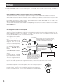
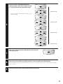
Iris Reader
Operating Instructions
BM-ET330E
ENGLISH
Model No.
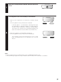
REJECT
ACCEPT
DEUTSCH
BM-ET330
Before attempting to connect or operate this product,
please read these instructions carefully and save this manual for future use.
ENGLISH VERSION
CAUTIONS:
• This unit is for indoor use only.
• Refer to the name plate on the bottom of this product to
verify identifications and power ratings.
• Refer to UL Listed access control panel's installation
instructions for compatibility information with Iris Reader,
Model BM-ET330E.
CAUTION:
• Read the label on the top and bottom of the unit for identification of this product, and the power ratings.
CAUTION
RISK OF ELECTRIC SHOCK
DO NOT OPEN
CAUTION: TO REDUCE THE RISK OF ELECTRIC SHOCK,
DO NOT REMOVE COVER (OR BACK).
NO USER-SERVICEABLE PARTS INSIDE.
REFER SERVICING TO QUALIFIED SERVICE PERSONNEL.
The lightning flash with arrowhead symbol, within an equilateral triangle, is
intended to alert the user to the presence of uninsulated "dangerous voltage"
within the product's enclosure that may
be of sufficient magnitude to constitute a
risk of electric shock to persons.
The exclamation point within an equilateral triangle is intended to alert the user
to the presence of important operating
and maintenance (servicing) instructions
in the literature accompanying the appliance.
We declare under our sole responsibility that the product to which this
declaration relates is in conformity with the standards or other normative
documents following the provisions of Directives EEC/73/23 and
EEC/89/336.
Nous déclarons sous note seule responsabilité que le produit auquel se
réfère la présente déclaration est conforme aux normes ou autres
documents normatifs conformément aux dispositions des directives
CEE/73/23 et CEE/89/336.
Nosotros declaramos bajo nuestra única responsabilidad que el producto
a que hace referencia esta declaración está conforme con las normas u
otros documentos normativos siguiendo las estipulaciones de las
directivas CEE/73/23 y CEE/89/336.
Noi dichiariamo sotto nostra esclusiva responsabilità che il prodotto a
cui si riferisce la presente dichiarazione risulta conforme ai seguenti
standard o altri documenti normativi conformi alle disposizioni delle
direttive CEE/73/23 e CEE/89/336.
Wij verklaren als enige aansprakelijke, dat het product waarop deze
verklaring betrekking heeft, voldoet aan de volgende normen of andere
normatieve documenten, overeenkomstig de bepalingen van Richtlijnen
73/23/EEC en 89/336/EEC.
Vi erklærer os eneansvarlige for, at dette produkt, som denne
deklaration omhandler, er i overensstemmelse med standarder eller
andre normative dokumenter i følge bestemmelserne i direktivene
73/23/EEC og 89/336/EEC.
Vi deklarerar härmed värt fulla ansvar för att den produkt till vilken
denna
deklaration
hänvisar
är
i
överensstämmelse
med
standarddokument, eller andra normativa dokument som framställs i
EEC-direktiv nr. 73/23 och 89/336.
Ilmoitamme yksinomaisella vastuullamme, että tuote, jota tämä ilmoitus
koskee, noudattaa seuraavia standardeja tai muita ohjeellisia asiakirjoja,
jotka noudattavat direktiivien 73/23/EEC ja 89/336/EE. säädöksiä.
Vi erklærer oss alene ansvarlige for at produktet som denne erklæringen
gjelder for, er i overensstemmelse med følgende normer eller andre
normgivende dokumenter som følger bestemmelsene i direktivene
73/23/EEC og 89/336/EEC.
The serial number of this product may be found on the bottom of the unit.
You should note the serial number of this unit in the space
provided and retain this book as a permanent record of your
purchase to aid identification in the event of theft.
Model No.
Serial No.
WARNING:
• To prevent fire or electric shock hazard, do not expose this appliance to rain or moisture. The apparatus shall not be exposed to dripping or splashing and that
no objects filled with liquids, such as vases, shall be placed on the apparatus.
• All work related to the installation of this product should be made by qualified service personnel or system installers.
2
IMPORTANT SAFETY INSTRUCTIONS
1) Read these instructions.
2) Keep these instructions.
3) Heed all warnings.
4) Follow all instructions.
5) Do not use this apparatus near water.
6) Clean only with dry cloth.
7) Do not block any ventilation openings. Install in accordance with the manufacturer's instructions.
ENGLISH
8) Do not use near any heat sources such as radiators, heat registers, stoves, or other apparatus (including amplifiers) that
produce heat.
9) Do not defeat the safety purpose of the polarized or grounding-type plug. A polarized plug has two blades with one wider
than the other. A grounding-type plug has two blades and a third grounding prong. The wide blade or the third prong are
provided for your safety. If the provided plug does not fit into your outlet, consult an electrician for replacement of the
obsolete outlet.
10) Protect the power cord from being walked on or pinched particularly at plugs, convenience receptacles and the points
where they exit from the apparatus.
11) Only use attachments/accessories specified by the manufacturer.
12) Refer all servicing to qualified service personnel. Servicing is required when the apparatus has been damaged in any way,
such as power-supply cord or plug is damaged, liquid has been spilled or objects fallen into the apparatus, the apparatus
has been exposed to rain or moisture, does not operate normally, or has been dropped.
13) All interconnecting devices must be UL Listed.
3
LIMITATION OF LIABILITY
This Product is used to recognize an individual person by using Iris data, and is not designed to protect against “theft” or
“crime” independently.
IN NO EVENT SHALL MATSUSHITA ELECTRIC INDUSTRIAL CO., LTD. BE LIABLE TO ANY PARTY OR ANY PERSON,
EXCEPT FOR REPLACEMENT OR REASONABLE MAINTENANCE OF THE PRODUCT, FOR THE CASES, INCLUDING BUT
NOT LIMITED TO BELOW:
(1) ANY DAMAGE AND LOSS, INCLUDING WITHOUT LIMITATION, DIRECT OR INDIRECT, SPECIAL, CONSEQUENTIAL OR
EXEMPLARY, ARISING OUT OF OR RELATING TO THE PRODUCT;
(2) PERSONAL INJURY OR ANY DAMAGE CAUSED BY INAPPROPRIATE USE OR NEGLIGENT OPERATION OF THE USER;
(3) UNAUTHORIZED DISASSEMBLE, REPAIR OR MODIFICATION OF THE PRODUCT BY THE USER;
(4) INCONVENIENCE OR ANY LOSS ARISING OUT OF NON-RECOGNITION WHEN IRIS DATA IS ALREADY ENROLLED,
DUE TO ANY REASON OR CAUSE OTHER THAN ANY FAILURE OR PROBLEM OF THE PRODUCT;
(5) ANY PROBLEM, CONSEQUENTIAL INCONVENIENCE, OR LOSS OR DAMAGE, ARISING OUT OF THE SYSTEM COMBINED BY THE DEVICES OF THIRD PARTY;
(It might be a case that the entrance-gate control system, for example, combining the Product and the electric lock
devices, does not open/close the door properly because of before-mentioned reasons or other causes of such system
except for the Product.)
(6) ANY LOSS OR DAMAGE, OR CLAIMS ARISING OUT FROM LOSS OR LEAK OF PC DATA INCLUDING IRIS DATA IN THE
IRIS SERVER OR CARDS;
(Iris data is nature of privacy. The customer shall be responsible for any Iris data stored in the Iris server or cards.)
(7) INCONVENIENCE OR ANY LOSS ARISING WHEN IMAGES ARE NOT DISPLAYED, DUE TO ANY REASON OR CAUSE
INCLUDING ANY FAILURE OR PROBLEM OF THE PRODUCT;
(8) ANY CLAIM OR ACTION FOR DAMAGES, BROUGHT BY ANY PERSON OR ORGANIZATION BEING A PHOTOGENIC
SUBJECT, DUE TO VIOLATION OF PRIVACY WITH THE RESULT OF THAT SURVEILLANCE-CAMERA’S PICTURE,
INCLUDING SAVED DATA, FOR SOME REASON, BECOMES PUBLIC OR IS USED FOR THE PURPOSE OTHER THAN
SURVEILLANCE
TRADEMARKS AND REGISTERED TRADEMARKS
• Microsoft® Windows® is a registered trademark of Microsoft Corporation in the United States and/or other countries.
• Adobe® Reader® and Acrobat® Reader® are registered trademarks of Adobe Systems Incorporated in the United States
and/or other countries.
• Private idTM is a trademark of Iridian Technologies in the United States.
• Other company names and product names appearing in these operating instructions are registered trademarks or trademarks of the company concerned.
4
CONTENTS
IMPORTANT SAFETY INSTRUCTIONS ...................................................................................................... 3
LIMITATION OF LIABILITY ......................................................................................................................... 4
TRADEMARKS AND REGISTERED TRADEMARKS ................................................................................... 4
PREFACE .................................................................................................................................................... 6
FEATURES .................................................................................................................................................. 7
PRECAUTIONS ........................................................................................................................................... 8
DOCUMENT CONVENTION ....................................................................................................................... 10
NOTIFICATION ABOUT THIS DOCUMENT ............................................................................................... 11
MAJOR OPERATING CONTROLS AND THEIR FUNCTIONS .................................................................... 12
■ External View ...................................................................................................................................... 12
■ Rear View ........................................................................................................................................... 13
■ Internal View ....................................................................................................................................... 13
SPECIFICATIONS OF WIEGAND CONNECTORS (FOR CARD READER) ................................................. 15
SPECIFICATIOS OF RS-485 CONNECTORS (FOR CARD READER) ......................................................... 15
SPECIFICATIONS OF WIEGAND CONNECTORS (FOR ACCESS CONTROL PANEL) ............................. 15
SPECIFICATIONS OF RS-485 CONNECTORES (FOR ACCESS CONTROL PANEL)................................. 16
SPECIFICATIONS OF ALARM OUTPUT CONNECTORS ........................................................................... 16
INSTALLATION AND CONNECTIONS ....................................................................................................... 17
■ Preparation ......................................................................................................................................... 18
■ Notification about the Installation Site ................................................................................................ 18
■ Installation Space and Recognition Range ........................................................................................ 19
■ Installation .......................................................................................................................................... 20
INSTRUCTIONS FOR PROPER ENROLLMENT AND RECOGNITION ....................................................... 22
OPERATING PROCEDURES (INSTRUCTIONS FOR IRIS READER USERS) ............................................. 23
■ How to Position Your Eyes in the Mirror ............................................................................................. 23
■ If You Have Difficulty in Eye Positioning ............................................................................................ 25
■ If You are Wearing an Eyepatch, etc. ................................................................................................ 25
■ Cases of Enrollment/Recognition Failure ........................................................................................... 25
■ How to Carry out Enrollment .............................................................................................................. 26
■ How to Carry out Recognition ............................................................................................................ 28
TROUBLESHOOTING ................................................................................................................................ 32
■ When Enrollment/Recognition Becomes Invalid ................................................................................ 32
■ Before Requesting for Repair ............................................................................................................ 33
SPECIFICATIONS ....................................................................................................................................... 35
STANDARD ACCESSORIES ....................................................................................................................... 36
5
PREFACE
Iris Reader BM-ET330E is used in an access control system. The iris reader, which captures a user's iris image, is available for
following uses.
• As an enrollment iris reader for iris image capturing and iris server enrollment
To activate iris recognition, it is necessary to capture the iris images of a user and enroll the iris data in the iris server.
An iris reader generates iris data from iris images captured, and transfers the data to the iris server in the LAN (Local Area
Network). The iris data is enrolled in the iris database of the iris server. Up to 5 025 users can enroll their iris data. *1
*1 For iris data enrollment, you need to install the optional Administration Software BM-ES330E. The PC needs to have
Microsoft® Windows® operating system installed.
The total number of users that can be enrolled differs depending on the total licence numbers of the User Licence Software
BM-EU30000E Series.
• As a recognition iris reader for iris recognition
Iris data of up to 1 000 users can be distributed from the iris server to iris readers. If the iris data of user has been distributed to a recognition iris reader, or if a card reader (connected to a recognition iris reader) reads the iris data out of a card,
the iris reader can recognize the user in approx. 1 seconds. *2 The user can check the recognition result with the result
indicator (ACCEPT/REJECT) on the front panel of the iris reader.
*2 The recognition time may differ
For enrollment*
depending on capturing condiCaptures iris images of both eyes, generates iris data from
tions.
the iris images, and enrolls the iris data in the iris server. *
3
If a card writer is connected to the iris server, iris data
* The iris reader captures the iris
enrolled in the iris server can be written into a card. *
images of both eyes at the
Enrollment
same time, but the iris data of
Iris server
each eye is enrolled separately.
Card writer
Enrollment/recognition by one
eye capturing is also available.
Enrolled iris data is distributed
If no corresponding iris data
to iris readers.
*4 Refer to BM-ES330E User’s
has been found in
the iris reader, the iris reader
Manual
accesses the administration
(supplied with Administration
software to execute server
certification.
Software BM-ES330E) for details
Recognition
on available cards and card
Administration Software BM-ES330E*
writers.
User Licence Software BM-EU30000E Series
For recognition*
*5 Capturing diagnosis is made
(1) Captures the iris images of both eyes.
(2) Recognizes a user by checking the iris
Iris database
by the administration software
images with the iris data (that is distributed
at the time of enrollment.
to the iris reader or that is read out by the
card reader connected to the iris reader). *
*6 The user is recognized with the
(3) Indicates the recognition result.
iris data of either eye.
7
* Up to 256 iris readers (enrollment and recognition iris readers) can be connected to the iris server in the LAN.
7
3
4
5
7
6
• Iris recognition technology is a way to identify a person with iris patterns (an iris is
the thin plate-shaped film in front of the eyeball), which differ among each person.
The iris pattern of the left eye differs from that of the right eye.
• Using iris readers, users can carry out recognition without touching any devices.
• In the iris recognition process, the users are recognized with the enrolled iris data.
Iris
Retina
Pupil
6
FEATURES
• Automatic guidance and recognition by voice guidance and guide indicator
When a user is within 50 cm {1.64 ft.} of the front of an iris reader, the voice guidance will start. Moving to the point where
the user can see both eyes in the mirror according to the voice guidance or guide indicator, the user's iris images will be
automatically captured and the user will be recognized from the iris data. The recognition range of the iris reader is
between approx. 30 cm {0.98 ft.} and 40 cm {1.32 ft.}
• One-time capturing of both eyes enables recognition in approx. 1 seconds*1
This iris reader captures the iris images of both eyes at the same time, generates iris data from the iris images, and compares the data with that distributed to the recognition iris reader or that read out by the card reader connected to the iris
reader. If the iris data of either eye is corresponding with the iris data that is distributed or that is read out, you will be recognized as an enrolled user. The recognition time will be approx. 1 seconds.*1
If no corresponding iris data is found in the recognition iris reader, the iris reader will transfer the data to the iris server. The
iris server will compare the transferred iris data with those enrolled in the iris database for certification. (In this document,
the certification by the iris server is called "server certification".) The recognition time will be approx. 10 seconds.*2
*1 The recognition time may differ depending on capturing conditions.
*2 The recognition time may differ depending on the traffic of the network or the total number of the enrolled users.
• Built-in video surveillance camera
The iris reader has a built-in minisize colour camera. You can record the facial image of a user by connecting this camera
and a recorder. Using the recognition result outputs (REJECT) of the iris reader, you can record only users that have not
been recognized.
• Access control system can be composed.
Iris readers and the iris server can compose an access control system in combination with access control panels*3, card
readers*3, and electric locks*3, etc.
*3 These devices are independent to BM-ET330E.
• Supporting a common access control interface
Recognition result outputs support Wiegand/RS-485*4, which is one of the interfaces commonly used for access control
systems. Any access control panel supporting the Wiegand/RS-485 interface can be directly connected to the iris reader.
The iris reader also has a Wiegand/RS-485 input. Any card reader supporting the Wiegand/RS-485 interface can be directly connected to the iris reader for composing an access control system.
*4 Our exclusive protocol is employed.
• Recognition is available using a card that includes iris data
By using the iris server and a card writer, you can write the iris data of user into a card. When the user passes the card
through the card reader connected to an iris reader, recognition is available.
7
PRECAUTIONS
General Safety Requirement
For Installation:
Refer all work related to the installation of the appliance to
qualified service personnel or system installers.
Consult an expert for help in evaluating load bearing
capacity of the installation surface and structure. If the
surface is not strong enough, the appliance may fall down.
Refer to the appliance specifications for weights.
To avoid fire or personal injury:
• Do not drop metallic parts through slots.
This could permanently damage the appliance.
• Do not attempt to disassemble the appliance.
There are no user-serviceable parts inside. Panasonic
is not responsible for regulatory compliance of a disassembled Panasonic appliance by unauthorized personnel. Contact qualified service personnel for maintenance.
• Do not strike or shake the appliance.
Handle the appliance with care, or it could cause the
trouble of it.
• Do not expose nor operate the appliance in
wet/damp conditions.
Take immediate action if the appliance gets wet. Refer
servicing to qualified service personnel. Moisture could
damage the appliance and also cause electric shocks.
• Do not use strong or abrasive detergents when
cleaning the appliance.
Use soft and dry cloth to clean the appliance when it is
dirty. When the dirt is hard to remove, use a mild detergent and wipe gently.
• Do not use the appliance beyond operating
requirements.
It is designed to operate properly for environment specified below:
Temperature
0 °C to 40 °C {32 °F to 104 °F}
Humidity
30 % to 80 % relative humidity, noncondensing
Source voltage 12 V DC/24 V AC
Important notes specific to the appliance:
• This unit has no power switch.
Power is supplied from an external 12 V DC/24 V AC
power-supply device. Refer to service personnel for
how to turn on/off the power.
Note: While the power is turned off, recognition and
entrance will NOT be available.
8
• The third-party external power supply should meet
the specifications. (Refer to p. 35.)
• Replacement part
Exchange the following parts for the same type.
F1: K5D402BK0002
• Adopting tamper-proof structure.
Refer to service personnel for relocating or servicing
the appliance.
As the unit has been designed in tamper-proof structure, buzzer sound will be activated with alarm notification when you try to open the front cover or detach the
appliance from the wall. Then, recognition will become
unavailable, the alarm notification will also be sent to
the iris server, and the stored data may be erased from
the unit.
• Use of near-infrared ray
Near-infrared ray is used when iris data are captured
by the appliance. The near-infrared ray is compliant
with the radiological safety standard of IEC60825-1.
• Indication label
Refer to the indication placed on the bottom of the
appliance as to the indications of equipment classification and power source, etc.
• This appliance is not designed to prevent theft.
The appliance is designed to perform roles of capturing
personal iris data, of recognizing individuals and of producing output signals only. To ensure your
entrance/gate security, you must use the appliance
together with other security system or devices including
electric locks.
Panasonic is NOT RESPONSIBLE FOR ANY CRIME OR
TROUBLE CAUSED BY USING THIS APPLIANCE.
• In some cases, recognition or enrollment doesn’t
work properly.
It could be invalid in recognition or enrollment when the
appliance has difficulty in getting iris information due to
dirt in front of lens, reflection of glasses or insufficiency
of physical requirement.
• Iris data is a nature of privacy.
Take enough care not to leak the data out of the iris
server. It is also recommended that you should get an
agreement from a person to register his or her data.
• The settings of this appliance are configured by the
iris server.
The operational setting of this appliance is configured
by the optional Administration Software BM-ES330E*,
which is to be installed in the iris server.
Depending on the settings, the voice guidance will not
be output or the live indicator will be off at all times.
Refer to system administrators for details on settings.
* If the previous version of Administration Software (BMES300E or BM-ES300AE) is installed on the iris server,
you cannot set up iris readers or distribute iris data from
the iris server to iris readers.
• Take care not to pinch your hands or fingers
between the front panel and the body of this
appliance. That may cause injury.
• When the front panel is damaged, refer to the dealer.
It may affect iris image capturing and cause invalid
recognition.
• Avoid placing a receptacle that contains liquid such
as water.
When the liquid falls over the appliance, it may cause a
fire or electric shock.
• Follow all instructions. Otherwise, our liability will
be limited.
IN NO EVENT SHALL MATSUSHITA ELECTRIC INDUSTRIAL CO., LTD. BE LIABLE TO ANY PARTY, EXCEPT
FOR REPLACEMENT OR REASONABLE MAINTENANCE OF THE PRODUCT, FOR ANY DAMAGES AND
LOSSES, INCLUDING WITHOUT LIMITATION, DIRECT
OR INDIRECT, SPECIAL, CONSEQUENTIAL OR EXEMPLARY, ARISING OUT OF OR RELATING TO (A) USE
OF THE SYSTEM AND/OR DEVICES OTHER THAN THE
PRODUCT; (B) UNAUTHORIZED USE OF THE PRODUCT; (C) UNAUTHORIZED REPAIR OR MODIFICATION
OF THE PRODUCT.
For more details, refer to "LIMITATION OF LIABILITY"
(p. 4).
9
DOCUMENT CONVENTION
These operating instructions use the following convention when describing the use and operation of iris reader.
Access control system: The system that controls access through iris recognition by iris readers and an iris server, together
with access control panels, card readers, and electric locks, etc.
Administration Software: Panasonic Administration Software BM-ES330E (This software is sold separately, however, it must
be used in combination with iris readers.)
This software is used for administering iris enrollment/recognition. The total number of users that can be enrolled differs
depending on the total licence numbers of User Licence Software BM-EU30000E Series (This software is sold separately,
however, it must be used in combination with iris readers.). If User Licence Software BM-EU30000E Series is not installed
on the iris server, up to 25 users can be enrolled.
Distribution: To transfer enrolled data from the iris server to iris readers and to save the data in the iris readers
Enrollment: To save a user's iris data associated with the individual information (name and ID data, etc.) in the iris server
Iris data is enrolled using the administration software.
ID data: The data, which is enrolled with each user’s information in an access control system with a card reader
Iris reader: Panasonic Iris Reader BM-ET330E
Iris data: Data that are generated from captured iris images
Iris recognition: Way to identify a person with iris patterns, which differ between each person
Iris server: PC in which the following applications are installed
The iris server can administer all the iris readers connected in the LAN.
• Administration Software (BM-ES330E)
• User Licence Software (BM-EU30000E Series)
Recognition: To identify a user by comparing the iris data generated (from iris images captured) with the data enrolled in the
iris database or read out of a card
Server certification: Certification carried out by the iris server when no corresponding iris data is found in iris readers
The iris reader generates iris data from the iris images captured. Then, the iris data is transferred to the iris server in the
LAN, which carries out certification. The setting in the administration software will determine whether to carry out server
certification.
User Licence Software: Panasonic User Licence Software BM-EU30000E Series that is required to enroll iris data
You need to purchase the software which supports the total number of users enrolled. (Administration Software BMES330E supports 25 user licences.)
• For 100 users: BM-EU30100E
• For 1 000 users: BM-EU31000E
• For 3 000 users: BM-EU33000E
• For 5 000 users: BM-EU35000E
Voice guidance: One of the methods to guide the eyes of users to the capturing range
Voice guidance leads users with the voice output from the speaker of the iris reader.
The setting of voice guidance will be configured by the system administrator using Administration Software BM-ES330E.
The parameters are as follows. (Refer to system administrators for details on setting.)
• Guidance language can be selected from among 14 languages.
• Audio setting can be selected from "Mute” (Nothing is output.), "Simple” (Shutter sound and recognition result are output.) and "Full” (Voice guidance, shutter sound, and recognition result are output.).
Wiegand: Transmission protocol used as an access control system interface
Warning(s): Warning statements identify conditions or practices that could result in severe injury or loss of life.
Caution(s): Caution statements identify conditions or practices that could result in damage to this product or injury.
Note(s): Note statements identify special instruction, rule, or side comment related to the topic.
10
NOTIFICATION ABOUT THIS DOCUMENT
• This document describes basic operating instructions of Iris Reader BM-ET330E.
• Manuals supplied to Administration Software BM-ES330E, which is the software required for iris data enrollment, describe
the operating instructions of the software, examples of system composition, and setup guide. Normally, users of recognition iris readers do not have to read them. These manuals are intended for system installers and administrators.
• System installers and administrators should read the following manuals as well as this document.
To set up iris readers: BM-ET330E Setup Manual, BM-ET330E Software Installation Guide
To use Administration Software BM-ES330E: BM-ES330E User's Manual
These manuals are PDF documents contained on the CD-ROM that is supplied with Administration Software BM-ES330E.
To read PDF documents, you need to install Adobe® Reader® or Acrobat® Reader®, which you can obtain at the homepage of Adobe Systems Incorporated.
11
MAJOR OPERATING CONTROLS AND THEIR FUNCTIONS
■ External View
● Front View
q Mirror
This mirror is used for eye positioning at the time of iris
data enrollment/recognition. View the mirror from the
front side where you can position both eyes in the mirror.
w Guide indicator
When a user comes within 50 cm {1.64 ft.} of the front of
an iris reader, this indicator will appear in the mirror for
guidance. Adjust your eye position by following the
guide indicator or voice guidance from the speaker.
e Front panel
Eye image capturing cameras and a near-infrared light
are located behind this panel. Depending on the user,
the near-infrared light (blinking red light) can be seen.
Notes:
• Avoid covering the front panel with a hand or cloth,
etc. That may cause invalid recognition.
• Avoid pinching objects between the front panel and
the main unit. That may cause a malfunction.
r Eye image capturing cameras
These cameras, which are located behind the front
panel, are used for eye image capturing.
Note: Avoid covering these cameras with a hand or
cloth, etc. Or avoid placing smudges on these cameras. It may cause invalid recognition.
t Result indicators
These indicators inform you of recognition results.
ACCEPT: This indicator lights up when recognition is
successfully completed.
REJECT: This indicator lights up when recognition is
not successfully completed or the user's iris data is
not enrolled in the iris reader.
y Video surveillance camera
This colour camera, which is located behind the front
cover, is used for facial monitoring. If you connect this
camera to external equipment such as a digital disk
recorder, you can record user's face and surroundings
to check the capturing condition.
u Live indicator
This indicator is blinking during standby. The blinking
speeds up when a user stands where he/she can see
both eyes in the mirror and guidance starts. The indicator can be set to be continuously on or off. Refer to system administrators for details on the settings.
12
q
w
e
!0
r
REJECT
t
y
BM-ET330
ACCEPT
o
i
u
!1
i Speaker
This speaker outputs voice guidance that guides a
user’s position and gives the recognition result. The
voice guidance can be set to any of the following. Refer
to system administrators for details on the settings.
Mute: Voice guidance is not output.
Simple: Shutter sound and recognition result are output. Voice guidance is not output.
Full: Voice guidance, shutter sound, and recognition
result are output.
o Audio volume controller
This controller adjusts the audio level of voice guidance. For adjustment, use a Phillips screwdriver that is
3 mm {0.12 in.} in diameter and more than 25 mm {0.98
in.} long. It is recommended to use a non-conductive
driver.
Note: Avoid adding excessive force to the screwdriver.
That may damage the audio volume controller.
!0 Tilt handles
You can adjust the angle of the front panel by holding
these handles. Adjust the handles so as to position both
eyes at the centre of the mirror.
!1 Front cover
This cover is removed at the time of installation, connection or maintenance. Users should not open it.
(Refer to service personnel when the front cover needs
to be opened.)
■ Rear View
Remove the cable hole cover by loosening the screws with a Phillips screwdriver.
Mounting hook hole (x4)
System Instruction
Cable hole
(Used if you make a hole
on the wall and pass the cables)
Rear tamper detection switch*
Cable hole cover (Used if you lay cables along a wall surface)
Remove the cable hole cover by loosing the screws
with a Phillips screwdriver.
* Refer to the setup manual (PDF file) supplied
to the administration software.
Cable hole cover
■ Internal View
● Front View
Video surveillance camera
The lens is fixed. Do not touch.
Tamper detection buzzer
volume controller*
Connection terminal
Setup switches*
Setup cable connector*
Front tamper
detection switch
Cable hole
Video cable
(Video surveillance
camera output)
LAN connector
Mounting screw hole (10 Base-T/100 Base-TX)
* Refer to the setup manual (PDF file) supplied to the administration software.
13
● Connection terminal
@1
Pin No.
q
w
e
r
t
y
u
i
o
!0
q Wiegand power (card reader)
Supplies power to a card reader.
!2 RS-485 (B) (access control panel)
A signal (RS-485 (B)) is input from or output to an
access control panel.
w Wiegand GND (card reader)
This is the ground terminal for the power supply and
communication between the iris reader and a card
reader.
!3 RS-485 (A) (card reader)
A signal (RS-485 (A)) is input from or output to a card
reader.
e Wiegand DATA0 (card reader)
A signal (DATA0) is input from a card reader to this terminal.
!4 RS-485 (B) (card reader)
A signal (RS-485 (B)) is input from or output to a card
reader.
r Wiegand DATA1 (card reader)
A signal (DATA1) is input from a card reader to this terminal.
!5 Alarm input1 (recognition start/buzzer)
An alarm signal is input to this terminal to start recognition or activate buzzer sound.
t Wiegand ACCEPT-LED (access control panel)
A signal (Wiegand ACCEPT-LED) is input to control the
ACCEPT indicator of this iris reader when Wiegand output is set up.
!6 Recognition result output1 (ACCEPT)
This terminal is activated when recognition is successfully completed.
y Wiegand power (access control panel)
The iris reader works even when nothing is connected
to this terminal.
u Wiegand GND (access control panel)
This is the ground terminal for communication between
the iris reader and an access control panel.
i Wiegand DATA0 (access control panel)
A signal (DATA0) is output from this terminal to an
access control panel.
o Wiegand DATA1 (access control panel)
A signal (DATA1) is output from this terminal to an
access control panel.
!0 Wiegand REJECT-LED (access control panel)
A signal (Wiegand REJECT-LED) is input to control the
REJECT indicator of this iris reader when Wiegand output is set up.
!1 RS-485 (A) (access control panel)
A signal (RS-485 (A)) is input from or output to an
access control panel.
14
!1
!2
!3
!4
!5
!6
!7
!8
!9
@0
!7 Recognition result output2 (REJECT)
This terminal is activated when recognition is not successfully completed.
!8 Alarm output1 (power status)
This terminal is closed and low when power is supplied
from an external power-supply device to the iris reader.
The terminal is opened when the power supply is shut
down.
!9 Alarm output2 (tamper detection)
This terminal is activated when the iris reader enters the
"tamper detection" mode by the front/rear tamper detection switch (activated until the "tamper detection" mode
is cancelled).
@0 GND
This is the common terminal for the alarm output connectors.
@1 Power input terminals
12 V DC (+12 V at the left/GND at the right) or 24 V AC
SPECIFICATIONS OF WIEGAND CONNECTORS (FOR CARD READER)
Pin No.
Port Name
1
POWER
2
GND
3
4
I/O
OUT
Signal Description
Remarks
Wiegand 5 V
5 V, 100 mA (Max)
–
Wiegand GND
0V
DATA 0
IN
Wiegand DATA 0
0 V to 5 V, 24 mA (Max), Wiegand I/F
Active low
DATA 1
IN
Wiegand DATA 1
0 V to 5 V, 24 mA (Max), Wiegand I/F
Active low
SPECIFICATIONS OF RS-485 CONNECTORS (FOR CARD READER)
Pin No.
Port Name
I/O
Signal Description
Remarks
RS-485 (A)
IN/OUT
RS-485 (A)
To the RS-485B
terminal of
RWK400
(A)
13
RS-485 (B)
IN/OUT
RS-485 (B)
To the RS-485A
terminal of
RWK400
(A)
14
(B)
(B)
Differential input: ± 0.2 V or more
Differential output: ± 2 V or more
(When termination is ON)
Differential input: ± 0.2 V or more
Differential output: ± 2 V or more
(When termination is ON)
SPECIFICATIONS OF WIEGAND CONNECTORS (FOR ACCESS CONTROL PANEL)
Pin No.
Port Name
I/O
5
ACCEPT-LED
IN
Wiegand ACCEPT-LED
0 V to 5 V, 24 mA (Max), Wiegand I/F
Active low,Pulse width: 200 ms or more
6
POWER
IN*
Wiegand 5 V
5V
7
GND
Wiegand GND
0V
8
DATA 0
OUT
Wiegand DATA 0
0 V to 5 V, 24 mA (Max), Wiegand I/F
Active low
9
DATA 1
OUT
Wiegand DATA 1
0 V to 5 V, 24 mA (Max), Wiegand I/F
Active low
10
REJECT-LED
Wiegand REJECT-LED
0 V to 5 V, 24 mA (Max), Wiegand I/F
Active low, Pulse width: 200 ms or more
–
IN
Signal Description
Remarks
* This port is for wiring designation convenience only.
15
SPECIFICATIONS OF RS-485 CONNECTORS (FOR ACCESS CONTROL PANEL)
Pin No.
Port Name
I/O
Signal Description
Remarks
(A)
11
RS-485 (A)
IN/OUT
RS-485 (A)
12
RS-485 (B)
IN/OUT
RS-485 (B)
(B)
(A)
(B)
Differential input: ± 0.2 V or more
Differential output: ± 2 V or more
(When termination is ON)
Differential input: ± 0.2 V or more
Differential output: ± 2 V or more
(When termination is ON)
SPECIFICATIONS OF ALARM OUTPUT CONNECTORS
Pin No.
Port Name
I/O
15
OUTPUT
RECOGNITION
START/
BUZZER
IN
16
OUTPUT
ACCEPT
Signal Description
Remarks
Alarm input 1
(recognition start/buzzer)
0 V to 5 V, 24 mA (Max),
Active low,
Pulse width: 200 ms or more
OUT
Recognition result output 1
(recognition ACCEPT)
24 V, 24 mA
Open collector output
Normally Open contact
Active low, Pulse width: 0.1 s to 60 s
17
OUTPUT
REJECT
OUT
Recognition result output 2
(recognition REJECT)
24 V, 24 mA
Open collector output
Normally Open contact
Active low, Pulse width: 0.1 s to 60 s
18
OUTPUT
POWER
DETECTION
OUT
Alarm output 1
(power status)
24 V, 24 mA
Open collector output
Normally Close contact
19
OUTPUT
TAMPER
DETECTION
OUT
Alarm output 2
(tamper detection)
24 V, 24 mA
Open collector output
Normally Open contact
Active low
20
GND
Alarm output
(COMMON)
0 V for ALARM OUTPUT
–
Note: You will set up Wiegand/RS-485 communication, pulse width of Recognition result output 1/2, and function of Alarm
input 1 with the administration software. Refer to system administrators.
16
INSTALLATION AND CONNECTIONS
WARNING
The installation described in these figures should be made by qualified service personnel or trained system installers.
Caution: Attach this iris reader to a flat wall with the supplied mounting bracket. After the installation, secure the iris reader to
prevent dropping.
Note: These operating instructions only describe how to install the iris reader to the wall. This iris reader will not operate properly if you do not complete the setup. Refer to the setup manual (PDF file) supplied to the optional administration software.
System Instruction
Access Control
Panel *
Iris Server *
Access Control
Server *
LAN
DB
LAN
Wiegand/RS-485
Administration
Software *
REJECT
ACCEPT
Wiegand/
RS-485
LAN
LAN
BM-ET330E
(for recognition)
REJECT
Card Reader *
Electric Lock*
ACCEPT
Wiegand/RS-485
REJECT
ACCEPT
Wiegand/
RS-485
BM-ET330E
(for enrollment)
BM-ET330E
(for recognition)
Card Reader *
* These products are independent to BM-ET330E.
.
● Description about the Connection Example
• When the power supply is shut down, an alarm signal is supplied from the alarm output 1 (power status) to alarm devices.
• When the front cover is removed from an iris reader or the iris reader is removed from the wall, an alarm signal is sent from
the alarm output2 (tamper detection) to alarm devices.
• When recognition is not successfully completed, an alarm signal is sent from the recognition result output2 (REJECT) to a
digital disk recorder. Then, the digital disk recorder automatically records the images output from the video surveillance
camera.
17
■ Preparation
Prepare the following items before the installation. The necessary items and their lengths differ depending on situation.
● Preparing the Necessary Items
Item
Item number/Recommended type
Use
Power cable
UL style 1015 (AWG 14-18) or
equivalents
Necessary when supplying power from
the external power-supply device to
the iris reader
Maximum distance: 10 m {32.8 ft.}
Solder both ends of the cable with M3
screw clamp terminals.
Coaxial cable
LAN cable
UL Listed NEC type CM or
CL2, RG-6/U type
For connection between an external
video-input device and the iris reader
Recommended distance: 20 m
{65.6 ft.} or less
Connect both ends with BNC plugs.
UL style 1666, CSA-FT4 or equivalents
Necessary for communication between
the iris readers and iris server
10 Base-T/100 Base-TX (Category 5)*1
Anchor bolt
M6
Required when installing the mounting
bracket over the wall with the unicorn
anchor
*1 Only cables without connector covers are usable.
Notes:
• When you use the alarm output and Wiegand terminals, you need optional cables suited for the connectors of external
devices. Use the UL style 1571 or equivalents, AWG 22 - 16 wire.
• When you use the RS-485 terminals, you need optional twisted pair cables (AWG 22 - 16) suited for the connectors of
external devices.
• It is recommended to use shielded twisted pair cables for the open collector output connectors (!6 - !9). (GND @0 is to be
paired.)*2
2
* !6, !9, and @0 are Pin No. Refer to p.16.
● Cable Preparation
Power cable (with sealing)
25 mm {1 in.} or less
■ Notification about the Installation Site
This iris reader is limited to indoor use.
Near-infrared light (contained in sunlight, incandescent light and halogen light) are used for iris image capturing by the iris
reader. If the iris reader is installed in a place which receives this light directly, it may cause invalid iris data
enrollment/recognition, as the iris reader cannot capture iris images properly.
Keep the iris reader away from the following. Otherwise, light may affect on the iris reader.
• Outdoor places
• Direct sunlight or light reflection
• Incandescent or halogen lighting
• Places where the iris reader or the user's eyes are directly exposed to light
18
Note: A quantity of acceptable near-infrared ray is 500 µW/cm2 or less.
• Places near the light reflection (from a mirror, etc.)
• Places where the amount of light is not appropriate for operation
Keep the iris reader away in the following, in addition to the above surroundings.
• Vibration (It may cause invalid iris image capturing and recognition. It may also cause other trouble or damage.)
• Places whose humidity is not between 30 % and 80 % and whose temperature is not between 0 °C and 40 °C {between
32 °F and 104 °F}
If the iris reader is located in an area exceeding these ranges, it may cause damage or a malfunction.
• Noise (for example, places near air conditioners or ventilators)
• Electricity
When objects made of glass or acrylic, etc. are located between an iris reader and a user, enrollment or recognition
may fail due to the light refraction, light reflection, or sensor malfunction.
■ Installation Space and Recognition Range
● Keep the Installation Space.
The installation space described in the following illustrations is required.
Note: The height of the iris reader, shown in the figure, is a recommendation. The centre of the optical axis and upside/downside limit of the eye position will differ depending on the installation height.
400 mm {16 in.}
700 mm {28 in.}
1 100 mm {43 in.}
Keep this area free
from obstructions
Height of the iris reader
1 300 mm {51 in.} or more
(recommended)
Keep this area free
from obstructions
400 mm {16 in.}
700 mm {28 in.}
1 100 mm {43 in.}
Floor
● Check the Capturing Range.
If the height of the iris reader is 1 300 mm {54.3 in.} as
described in the previous "Side View" illustration, the recognition range will become as follows.
Note: If your eye position is higher than the upside limit,
bend down. If your eye position is lower than the downside limit, get on a pedestal, etc.
700 mm {28 in.} 700 mm {28 in.}
Side View
400 mm {16 in.} 400 mm {16 in.}
Top View
1 710 mm
{67.3 in.}
Upside limit of
the eye position
Side View
35 °
—15 °
1 480 mm {58.3 in.}
Centre of optical axis
(Recommended
installation height)
1 380 mm
{54.3 in.}
Downside limit of
the eye position
300 mm {12 in.}
11 mm {0.43 in.}
1 300 mm {54.3 in.}
Bottom of
0 mm {0 in.}
the iris reader unit
400 mm {15.7 in.}
19
20 mm
{0.79 in.}
8 mm {0.31 in.}
16 mm
{0.63 in.}
109 mm {4.29 in.}
Mounting
hook (x4)
41 mm
{1.61 in.}
30 mm
{1.18 in.}
52.5 mm
{2.06 in.}
The iris reader can be mounted over the wall as described.
1. Bury the anchor into the wall. (Refer to the illustration of
"Dimensions of the Mounting Bracket".) The anchor bolt
should meet the standards shown in the illustration.
192 mm {7.56 in.}
150 mm {5.90 in.}
27 mm
{1.06 in.}
201mm {7.91in.}
158.5 mm {6.24 in.}
144.3 mm {5.68 in.}
178.5 mm {7.03 in.}
Cautions:
• Mount the iris reader to the flat and firm wall with the
supplied mounting bracket. Besides, secure the iris
reader and bracket with the supplied mounting screw,
at the time of the mounting. Otherwise, it may cause
dropping, trouble or injury.
• Check if the wall has enough strength for mounting and
no dents. Otherwise, the rear tamper detection switch
will not be pressed and the tamper detection mode will
be activated.
119 mm {4.68 in.}
■ Installation
73.5 mm
50 mm {1.97 in.}
{2.89 in.}
83.7 mm {3.29 in.}
Projection of the tamperproof switch
Dimensions of the mounting bracket
6 mm {0.24 in.} or less
Wall
2. Attach the iris reader to the mounting bracket.
Mounting hook (x4)
φ13 mm
{0.51 in.}
or less
Anchor bolt
φ11.5 mm
{0.45 in.}
or less
(1) Attach the supplied
Equivalent to
anchor M6
Anchor bolt
Mounting
bracket
mounting bracket to the
wall, and then attach the
iris reader to the mounting
bracket.
Washer
Mounting bracket
1 mm {0.04 in.} (D)
Notes:
• Wall's capacity is 100 N or more.
• Anchor bolt's capacity is 100 N or more (per one).
• Take a side view to make sure that all the mounting
hook holes of the iris reader have been hung over the
mounting hooks of the mounting bracket. If the rear
tamper detection switch is not be pressed, the iris reader may not work properly.
Video cable and power cable
(Refer to p. 18 for the
specifications of these cables.)
(2) Hang the mounting hook
holes of the iris reader
over the mounting hooks
of the mounting bracket.
(3) Fix the iris reader and
mounting bracket with the
supplied mounting screw.
(4) Connect the cables to the
iris reader.
Note: If you lay cables along a wall surface, replace the cable hole
cover on the bottom of the iris reader. (Refer to p. 13.)
Wall
Wall
Tamper detection
switch
20
3. When you use the built-in video surveillance camera,
connect the video cable of the video surveillance camera to the BNC connector of the video input cable connected to an external device (for example, a digital disk
recorder).
Fix the power
cable to the iris
reader with the
supplied
clamping tool and
clamping screw.
7. Attach the LAN cable to the LAN connector.
Video cable
Coaxial cable
from a connected device
4. Connect the cables to the Wiegand and alarm output
connectors as shown in the illustration. (Refer to p. 14
for details on each cable connection.)
Attach the ferrite core
supplied to the LAN cable.
8. After installation, attach the front cover to the iris reader
by fixing the supplied tamper proof screws with the
supplied screwdriver tool.
Cables
5. Connect the power cable to the iris reader.
Cautions:
• Pass the cables through the cable hole and lead
them out of the rear or bottom side.
• If the cables are lead out of the bottom side, coat
the cables with cable covers, etc.
• When using 12 V DC power cable, do not mistake +
and –. The wrong cable connection may cause
problems.
• Use an external power-supply device that complies
with the safety standards. (Refer to p. 35.)
6. Fix the power cable to the iris reader with the supplied
clamping tool and clamping screw to avoid disconnection.
The tamperproof screw holes are
inclined to the front side approx. 15 °
as you can easily fasten the screws
while the iris reader is mounted to the wall.
Approx. 15 °
Tamperproof screws x 2
Notes:
• Take care not to lose the supplied tamperproof
screwdriver tool, as it is required at the time of relocation and setting.
• The front panel is covered with the protection film
for preventing damage. Be sure to detach the film
after the installation process of the iris reader.
21
INSTRUCTIONS FOR PROPER ENROLLMENT AND RECOGNITION
You (user) should follow the instructions mentioned in this page for proper enrollment and recognition.
• Open your eyes as wide as you can so as not to hide the irises with eyelids and eyelashes.
Not preferable
Preferable
• For users wearing glasses/sunglasses (for enrollment)
Take off the glasses when enrolling the iris data in the iris server.
• For users wearing glasses/sunglasses (for recognition)
With this iris reader, you can carry out iris recognition wearing glasses. However, in the following cases, you should take off the
glasses or move the front panel to adjust the eye position in the mirror.
• Take off the sunglasses whose lens colour is dark.
• When smudges are on the lenses, it may cause invalid iris image capturing. In
this case, wipe the lenses with a cloth.
• When light is reflecting on the lenses, it may cause invalid iris image capturing.
In this case, move your face or the iris reader's front panel upward or downward
to avoid reflection. If you still cannot recognize yourself, take off your
glasses/sunglasses.
Not preferable
• If you are wearing contact lenses:
With this iris reader, you can carry out iris enrollment/recognition wearing contact lenses. However, if a lens has slipped off the
eye's corneal surface, the contact edge may hide the iris images. That may cause invalid recognition. In this case, move the
contact lens back to the corneal surface by blinking.
• Follow the guide indicator and voice guidance by moving slowly.
If you move so fast that your iris image cannot be captured properly, it may cause invalid recognition Move as slowly as you
can when following the guide indicator and voice guidance.
22
OPERATING PROCEDURES (INSTRUCTIONS FOR IRIS READER USERS)
This section explains how to use the iris reader, enroll the iris data in the iris server, and recognize yourself with a recognition
iris reader in the following order.
• How to position your eyes in the mirror
This is a fundamental operating procedure. Please read here before enrollment and recognition to facilitate the operating
procedures.
• How to carry out enrollment
For iris recognition, you need to make the iris reader capture your iris image and enroll your iris data in the iris server. This
procedure explains how to enroll the iris data in the iris server using the iris reader. Follow the direction of system
administrators or operators when you carry out iris data enrollment.
• How to carry out recognition
This procedure explains how to recognize yourself with the iris reader after enrollment.
• How to recognize yourself with the iris reader and a card reader
This procedure explains how to recognize yourself with the iris reader and a card reader after enrollment.
■ How to Position Your Eyes in the Mirror
This iris reader captures the iris data of both eyes at one time. If the eyes are not positioned within the capturing range,
enrollment/recognition will be invalid. Before enrollment/recognition, you (the user) should stand in front of the iris reader as
follows and adjust your eye position. Even when you carry out enrollment/recognition while sitting, you should adjust your eye
position in the same way.
Note: If your eye position is higher than the upside limit, bend down. If your eye position is lower than the upside limit, get on a
pedestal, etc.
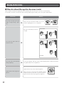
1. Stand where you can see the iris reader
from the front side.
Stand where you can hold the tilt handles with your
arms bent moderately. If you are standing within the
recognition range, an ellipse symbol will appear at the
centre of the mirror.
1
• The recognition range is within approx. 30 cm to
40 cm {0.98 ft. to 1.32 ft.} away from the iris reader.
• The recognition area differs depending on users.
However, the approximate recognition area is
where you can stand holding the tilt handles with
your arms bent moderately.
D is
ta
th e n c e b
e tw
eye
e
s
app
ro x . a n d m e n
{ 0 .9
30 c
i
8 ft.
m to r r o r :
to 1
.3 2 4 0 c m
ft.}
35 °
15 °
23
2. Hold the tilt handles at the sides of the front
panel.
Tilt handles
Keep bending your arms moderately while holding the
handles.
2
Front panel
(Avoid hiding with
a hand or cloth, etc.)
Eye image capturing cameras
(Avoid hiding with a hand
or cloth, etc.)
Caution: Take care not to pinch your hands or fingers
between the front panel and the body of this appliance.
3. Make sure that you can see both eyes in the mirror.
3
When the eyes are not positioned in the mirror, move to the point where you can see the eyes in the mirror or
adjust the angle of the front panel by holding the tilt handles.
4. Open your eyes widely and look at the
mirror from the front side.
4
Open your eyes as wide as you can so as not to hide
the irises with eyelids and eyelashes.
Not preferable
5. Look at the ellipse symbol in the mirror.
5
6. Then, focus on the eyes in the mirror.
The ellipse symbol appears to be divided into "two".
6
24
Preferable
7
7. Overlap your eyes on the "two"
ellipse symbols by moving the front
panel slowly, according to the voice
guidance and/or guide indicator.
This iris reader guides your eye position with
voice guidance and/or guide indicator.
Not preferable
Preferable
■ If You Have Difficulty in Eye Positioning
When trying the procedure of "How to Position Your Eyes in the
Mirror" (pp. 23 to 25), you may sometimes have difficulty in focusing on the eyes or seeing "two" ellipse symbols in the mirror. In this
case, cover either eye and position your opened eye over an eye
image capturing camera.
Note: Even if you carry out one-eye adjusting, capture left and
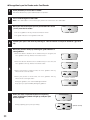
right eye separately to enroll both eyes.
Left eye image
REJECT
ACCEPT
Eye image capturing camera (Left)
Right eye image
REJECT
ACCEPT
Eye image capturing camera (Right)
■ If You are Wearing an Eyepatch, etc.
Enrollment/recognition using one eye capturing is available when you cannot have both eyes captured, due to an eyepatch,
etc. In this case, the voice guidance or guide indicator will lead you to position your opened eye over an eye image capturing
camera. (Refer to the illustrations in "If You Have Difficulty in Eye Positioning".) Position your eye on the eye image capturing
camera, according to the guidance.
■ Cases of Enrollment/Recognition Failure
•
•
•
•
•
You have closed your eyes or not opened your eyes widely enough during the capturing procedure.
You were wearing sunglasses whose lens colour is too deep to be captured
There were smudges on the glasses.
You were not looking at the mirror during capturing.
Your position is too near or too far away to be captured.
When you come within approx. 50 cm {1.64 ft.} of the iris reader, the guidance will start. The recognition range
between the eyes and mirror is approx. 30 cm to 40 cm {0.98 ft. to 1.32 ft.}.
25
■ How to Carry out Enrollment
The following is how to control the iris reader when your (the user's) iris data is enrolled in the iris server.
Notes:
• Follow the direction of system administrators or operators when you carry out enrollment.
• Your eyes (iris data) will be captured four times at the time of enrollment.
Wait until you can confirm the capturing result.
• Depending on the settings by the system administrators, voice guidance (voice guidance and/or shutter sound) may not
be output.
• The iris reader selects the iris data that is most suitable to enroll in the iris database. Then, the iris data transfers the data to
the iris server. Then, the data is enrolled in the iris server. If there are no suitable images, the iris server will display the
message to the system administrators or operators that the user needs to retry the capturing procedure.
System administrators or operators should configure the data in the iris server, which is required for enrollment, and direct a
user to carry out enrollment. Users (you) should control the iris reader as follows, directed by system administrators or
operators.
1
2
Stand (Sit down) in front of the iris reader.
Follow the directions of system administrators or operators.
If you are wearing glasses/sunglasses, take them off.
Follow the directions of system administrators or operators to
start iris image capturing.
3
4
• The voice guidance will say, "Please look into the mirror. Please
open your eyes wider."
• The guide indicator or voice guidance will start.
Position your eyes in the mirror by referring to" How to Position Your Eyes in the Mirror" (pp. 23 to
25).
Move your position slowly by following the guide indicator or
voice guidance.
• When the distance between the iris reader and you is too great, the
voice guidance will say, "Please move a little closer."
• When the distance between the iris reader and you is too short, the
voice guidance will say, "Please move back a little."
5
• When your position is right-of-centre, the voice guidance will say,
"Please move to the left a little."
• When your position is left-of-centre, the voice guidance will say,
"Please move to the right a little."
During the guidance, the near-infrared light will blink.
Keep your eyes opened widely during the guidance.
26
When your eyes are positioned within the
capturing range, all the allow symbols will light
up, and your eyes will be captured four times.
(Shutter sound)
Keep your eyes opened widely during your iris
image capturing.
(Shutter sound)
6
(Shutter sound)
(Shutter sound)
After your iris image has been captured four times, take your
eyes off the mirror.
7
8
9
Wait until you can confirm the capturing result, as you may need to retry the capturing.
Wait for the directions of system administrators or operators, as it will take approx. 10 seconds until the recognition
result is output.
Follow the direction by the system administrators or operators.
27
■ How to Carry out Recognition
The following is how to control the iris reader when a user (you), whose iris data has been enrolled in the iris server, carries out
recognition. This document will explain about:
• Recognition by an iris reader only
• Recognition by an iris reader and a card reader
Notes:
• To carry out the recognition by an iris reader only, your iris data needs to have been sent to recognition iris readers,
enrolled in the iris server, or written into a card. If your iris data has not been enrolled, refer to system administrators for
enrollment.
• Depending on the settings by the system administrators, voice guidance (voice guidance and/or shutter sound) may not
be output.
● Recognition by an Iris Reader only
Stand (Sit down) in front of the iris reader.
1
Follow the directions by system administrators or operators.
Move your face so as your eyes are positioned within 50 cm
{1.64 ft.} from the iris reader.
2
• The voice guidance will say, "Please look into the mirror."
• The guide indicator or voice guidance will start.
3
Position your eyes in the mirror by referring to " How to Position Your Eyes in the Mirror" (pp. 23 to
25).
Move your position slowly by following the guide indicator or
voice guidance.
• When the distance between the iris reader and you is too great, the
voice guidance will say, "Please move a little closer."
• When the distance between the iris reader and you is too short, the
voice guidance will say, "Please move back a little."
4
• When your position is right-of-centre, the voice guidance will say,
"Please move to the left a little."
• When your position is left-of-centre, the voice guidance will say,
"Please move to the right a little."
During the guidance, the near-infrared light will blink.
Keep your eyes opened widely during the guidance.
28
When your eyes are positioned within the capturing
range, all the allow symbols will light up, and your eyes
will be captured.
5
During capturing, open your eyes widely.
(Shutter sound)
After your iris image has been captured, take your eyes off the
mirror.
6
The recognition result is announced by a result indicator.
• When you are recognized as an enrolled user, "ACCEPT" will light
up.
• The voice guidance will say, "Identification completed."
7
REJECT
ACCEPT
It will take approx. 1 seconds between capturing and recognition. Depending on capturing conditions, it will take approx. 3
seconds. If server certification is carried out, it will take approx.
10 seconds. (The certification time may differ depending on the
traffic of the network or the total number of the enrolled users.)
• When the recognition is invalid, "REJECT" will light up.
• The voice guidance will say, "Sorry you were not identified."
The recognition result will be transferred to the access control
panel, accompanied by the user information such as the ID
data, etc.
REJECT
ACCEPT
Note: If the recognition becomes invalid frequently, refer to "TROUBLESHOOTING" (p. 32).
29
● Recognition by an Iris Reader and a Card Reader
1
Stand (Sit down) in front of the iris reader.
2
Pass a card through the card reader.
Follow the directions by system administrators or operators.
Note: If the card reader is a non-contact type, position the card close to the card reader.
Move your face so that your eyes are positioned within 50 cm
{1.64 ft.} from the iris reader.
3
• The voice guidance will say, "Please look into the mirror."
• The guide indicator or voice guidance will start.
4
Position your eyes in the mirror by referring to " How to Position Your Eyes in the Mirror" (pp. 23 to
25).
Move your position slowly by following the guide indicator or
voice guidance.
• When the distance between the iris reader and you is too great, the
voice guidance will say, "Please move a little closer."
• When the distance between the iris reader and you is too short, the
voice guidance will say, "Please move back a little."
5
• When your position is right-of-centre, the voice guidance will say,
"Please move to the left a little."
• When your position is left-of-centre, the voice guidance will say,
"Please move to the right a little."
During the guidance, the near-infrared light will blink.
Keep your eyes opened widely during the guidance.
When your eyes are positioned within the capturing
range, all the allow symbols will light up, and your eyes
will be captured.
6
During capturing, open your eyes widely.
30
(Shutter sound)
After your iris image has been captured, take your eyes off the
mirror.
7
The recognition result is announced by a result indicator.
• When you are recognized as an enrolled user, "ACCEPT" will light
up.
• The voice guidance will say, "Identification completed."
REJECT
ACCEPT
It will take approx. 1 seconds between capturing and recognition. Depending on capturing conditions, it will take approx. 3
seconds. If server certification is carried out, it will take approx.
10 seconds. (The certification time may differ depending on the
traffic of the network or the total number of the enrolled users.)
8
• When the recognition is invalid, "REJECT" will light up.
• The voice guidance will say, "Sorry you were not identified."
The recognition result will be transferred to the access control
panel, accompanied by the user information such as the ID
data, etc.
REJECT
ACCEPT
Notes:
• If the recognition becomes invalid frequently, refer to "TROUBLESHOOTING" (p. 32).
• When performing recognition by using a card that includes iris data, server certification is unavailable.
31
TROUBLESHOOTING
■ When Enrollment/Recognition Becomes Invalid
When iris data enrollment/recognition becomes invalid or takes too much time, check to see the following.
If the trouble cannot be corrected even after checking and trying the remedy, refer to the system administrator.
Check item
You may not open your eyes
widely enough during capturing.
Remedy
Keep your eyes opened as wide as you can
until the capturing process is completed.
Not preferable
Preferable
Not preferable
Be sure to look directly at the mirror right.
You may have been above or
below the mirror.
Preferable
You may have moved quickly
during capturing.
If you move quickly, that may cause invalid capturing. Move slowly by following
the guide indicator or voice guidance.
Light reflection may cause invalid recognition.
Light has been reflecting on the
glasses.
Move your face or the front panel upward or downward to prevent the reflection. If you still cannot recognize yourself, take off your glasses/sunglasses.
Not preferable
32
Check item
Remedy
The contact lenses may have
not been on the appropriate
position.
If a lens has slipped off the eye's corneal surface, the contact edge may hide the
iris images. That may cause invalid recognition. In this case, move the contact
lens back to the corneal surface by blinking.
You may have been wearing
colour contact lenses.
Depending on the lens colour, recognition may be invalid.
● Cases of Enrollment/Recognition Failure
•
•
•
•
•
You have closed your eyes or not opened your eyes widely during capturing.
You were wearing sunglasses whose lens colour is too deep to be captured
Smudges were sticking on the glasses.
You were not looking at the mirror during capturing.
Your position is too near or too far from the iris reader to be captured.
When you come within approx. 50 cm {1.64 ft.} of the iris reader, the guidance will start. The recognition range
between the eyes and mirror is approx. 30 cm to 40 cm {0.98 ft. to 1.32 ft.}.
■ Before
Requesting for Repair
Check to see the following before requesting for repair.
Do not attempt anything other than the described actions herein.
If the trouble cannot be corrected even after checking and trying remedy, contact your dealer.
Problem
The live indicator does not light
up.
Enrollment/Recognition is
invalid.
Check item
Remedy
• Power may not be supplied to the iris
reader.
• The indicator is set not to light up by the
administration software.
Refer to system administrators.
• Your iris data may not be enrolled in the iris
reader.
• You may not have passed your card
correctly through the card reader (if a card
reader is used).
Refer to system administrators.
• A smudge may be on the front panel or the
panel may be damaged.
Refer to p. 8.
(If the front panel needs
replacement, refer to service
personnel.)
33
Problem
Check item
Remedy
• You may not have opened your eyes widely
during capturing.
• You may have been looking above or below
the mirror.
• You may have moved quickly during
capturing.
• Light has been reflecting on the glasses.
• The contact lenses may have not been in
the appropriate position.
• You may have been wearing colour contact
lenses.
Enrollment/Recognition is
invalid.
In the following cases, the recognition/
enrollment will fail.
Refer to pp. 22, 23 to 25, and
32 to 33.
• You have closed your eyes or not opened
your eyes widely enough during capturing.
• You were wearing sunglasses whose lens
colour is too deep to be captured.
• Smudges were on the glasses.
• You were not looking at the mirror during
capturing.
• Your position is too near or too far from the
iris reader to be captured.
Voice guidance is not heard.
None of the guide indicator and
result indicator light up.
Buzzer sound is heard and all
of the guide indicator and
result indicator are blinking.
The ellipse symbol at the centre of the guide indicator is
lighting, but the iris reader
does not work.
34
• The audio level of voice guidance may be
set to the minimum.
• The voice guidance may be set to "Mute" by
the administration software.
Refer to system administrators.
• The iris data may be being distributed to the
iris reader, or the iris reader may be being
reset. The operation of the iris reader will be
available after waiting for a while. (In the
maximum case, it takes approx. 5 minutes.)
• If the iris reader still cannot be operable,
the operation of the iris reader will be
stopped by the settings of the administration software.
Refer to system administrators.
The "tamper detection" mode is activated.
Refer to system administrators.
The iris reader may be set to the "enrollment"
mode.
Refer to system administrators.
SPECIFICATIONS
General
Power source *1:
Power consumption:
Ambient operating temperature:
Ambient operating humidity:
Dimensions:
Weight:
Interface:
Network:
Network protocol:
Available card reader:
12 V DC/24 V AC
15 W
0 °C to +40 °C {32 °F to 104 °F}
30 % to 80 %
212 mm (W) x 216 mm (H) x 55 mm (D) {8.35 in. (W) x 8.50 in. (H) x 2.16 in. (D)}
2.1 kg {4.9 lbs.} (this iris reader only)
2.4 kg {5.3 lbs.} (with the mounting bracket)
Wiegand, RS-485
10 Base-T/100 Base-TX (Auto negotiation) *2
TCP/IP
RWK400 (Manufactured by HID Corporation)
Input/Output
Wiegand power (card reader):
5 V DC, 100 mA max.
Wiegand DATA0 (card reader):
0 V to 5 V DC, 24 mA max., Active low
Wiegand DATA1 (card reader):
0 V to 5 V DC, 24 mA max., Active low
Wiegand power (access control panel): 5 V DC (No connection available)
Wiegand DATA0 (access control panel): 0 V to 5 V DC, 24 mA max., Active low
Wiegand DATA1 (access control panel): 0 V to 5 V DC, 24 mA max., Active low
Wiegand ACCEPT-LED (access control panel): 0 V to 5 V, 24 mA (Max), Active low, Pulse width: 200 ms or more
Wiegand REJECT-LED (access control panel): 0 V to 5 V, 24 mA (Max), Active low, Pulse width: 200 ms or more
RS-485 (A), (B) (card reader):
Differential input: ± 0.2 V or more, Differential output: ± 2 V or more
(When termination is ON)
RS-485 (A), (B) (access control panel):
Differential input: ± 0.2 V or more, Differential output: ± 2 V or more
(When termination is ON)
Alarm input1 (recognition start/buzzer): 0 V to 5 V, 24 mA (Max), Active low, Pulse width: 200 ms or more
Recognition result output1 (ACCEPT):
Open collector output, Normally Open, Active low, Pulse width: 0.1 s to 60 s,
24 V DC, 24 mA
Recognition result output2 (REJECT):
Open collector output, Normally Open, Active low, Pulse width: 0.1 s to 60 s,
24 V DC, 24 mA
Alarm output1 (power status):
Open collector output, Normally Close (Low level), 24 V DC, 24 mA
Alarm output2 (tamper detection):
Open collector output, Normally Open, Active low, 24 V DC, 24 mA
Video surveillance camera output:
1 V [P-P] PAL composite 75 Ω BNC connector
Function
Iris recognition time:
Eye image capturing range:
Total number of users enrolled *4
BM-ET330E:
Iris server:
Voice guidance:
Guide indicator:
Live indicator:
Angular field view
(video surveillance camera):
Security function:
Approx. 1 seconds (After iris image capturing until the recognition result is output) *3
Approx. 10 seconds
(Server certification. After iris image capturing until the recognition result is output) *3
Approx. 30 cm to 40cm {0.98 ft. to 1.32 ft.} between the eyes and the mirror
1 000 users max.
5 025 users max.
14 languages supported (Japanese, English, German, French, Spanish, Italian,
Russian, Chinese, Korean, Portuguese, Turkish, Arabic, Dutch, and Swedish)
Mute, Simple (Shutter sound and recognition result), and Full (voice guidance, shutter sound, and recognition result) selectable
Front, Back, Left, and Right
Blinking, On, and Off selectable
Horizontal: 115 °, Vertical: 85° (Fixed)
Tamper detection switch
Iris data encryption
Note: Refer to the next page for the explanations of *1 to *4.
35
*1 The third-party external power-supply should meet the following specifications.
Output voltage:
12 V DC/24 V AC, ±0.5 V
Output current capacity:
1.5 A or more (DC/AC)
Rated ripple voltage/Ripple noise: 150 mV [P-P] or less
Overcurrent protection:
Enabled (mandatory)
*2 This iris reader supports auto negotiation. If you use a hub supporting auto sensing, connection may not be established
due to auto sensing malfunction.
*3 The recognition time may differ depending on capturing conditions, network conditions, or the total number of enrolled
users.
*4 User Licence Software BM-EU30000E Series (option) is required.
STANDARD ACCESSORIES
Operating Instructions (This document)....................................... 1 pc.
The following parts are used during installation procedures.
Mounting bracket ........................................................................ 1 pc.
Mounting screw (M5) ................................................................... 1 pc.
Front cover .................................................................................. 1 pc.
Tamperproof screw ...................................................................... 2 pcs.
Tamperproof screw driver tool ..................................................... 1 pc.
Clamping tool .............................................................................. 1 pc.
Clamping tool screw (M3) ........................................................... 1 pc.
Ferrite core ................................................................................... 1 pc.
36
Matsushita Electric Industrial Co., Ltd.
Osaka, Japan
http://www.panasonic.co.jp/global/
© 2005 Matsushita Electric Industrial Co., Ltd. All Rights Reserved.
N1004-1035
3TR002882BAA
Printed in Japan
Gedruckt in Japan