1
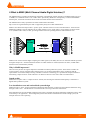
MTBK-R109 MADI Board
User Manual
Version: DOC-1.1 (May 2007)© 2007 Merging Technologies Inc.
Merging Technologies
Le Verney, CH-1070 Puidoux Switzerland
Tel: +41 21 946 04 44 ● Fax: +41 21 946 04 45
www.merging.com
1 IMPORTANT NOTICE:
Please read the following information very carefully before attempting any installation. Failure to comply with
the precise instructions may result in damage to your Merging hardware. Please read this entire section of the
manual carefully before installation.
1.1
STATIC DANGER NOTICE:
Please note that the Mykerinos board contains delicate electronic components that can be damaged or even
destroyed when exposed to static electricity. Take all necessary precautions not to discharge static electricity
when touching any of the Mykerinos components.
1.2
INFORMATION FOR THE USER:
Mykerinos and its daughter card comply with the following specifications:
EMC Emissions
EN 55022 : 1994 /A1 : 1995 /A2 : 1997 Class A ITE emissions requirements (EU)
FCC 47 CFR Part 15 Class A emissions requirements (USA)
EMC Immunity
EN 50082-1: 1992 EMC residential, commercial and light industrial generic immunity standard.
FCC Notice
This product has been tested and found to comply with the limits for a Class A digital device, pursuant to Part 15 of the
FCC rules. Operation is subject to the following two conditions: (1) This device may not cause harmful interference,
and (2) This device must accept any interference received, including interference that may cause undesired operation.
These limits are designed for providing reasonable protection against harmful interference in a residential installation.
This equipment generates, uses and can radiate radio frequency energy and, if not installed and used in accordance
with the instructions contained in this manual, may cause harmful interference to radio and television communications.
However, there is no guarantee that interference will not occur in a particular installation.
NOTE: Connecting this device to peripheral devices that do not comply with CLASS A requirements or using an
unshielded peripheral data cable could also result in harmful interference to radio or television reception. The user is
cautioned that any changes or modifications not expressly approved by the party responsible for compliance could void
the user’s authority to operate this equipment. To ensure that the use of this product does not contribute to interference,
it is necessary to use shielded I/O cables.
CE Notice
Such a
marking is indicative that this system’s devices meet the following applicable technical standards:
EN 55022 – “Information Technology Equipment - Radio disturbance characteristics Limits and methods of
measurement”
EN 50082-1: 1992 – “Electromagnetic compatibility – Generic immunity standard Part 1: Residential, commercial, and
light industry”
This product is classified for use in a typical Class A commercial environment, and is not designed or intended for use
in other EMC environments. The user of this product is obliged for proper use and installation of the product and for
taking all steps necessary to remove sources of interference to telecommunications or other devices.
-2-
2 MTBK-R109 Warranty Information
This product is warranted to be free of defects in materials and workmanship for a period of one year from the date of
purchase. Merging Technologies, Inc. extends this Limited Warranty to the original purchaser.
In the event of a defect or failure to confirm to this Limited warranty, Merging Technologies, Inc. will repair or replace
the product without charge within sixty (60) days. In order to make a claim under this limited warranty, the purchaser
must notify Merging Technologies, Inc. or their representative in writing, of the product failure. In this limited
warranty the customer must upon Merging Technologies, Inc. request, return the product to the place of purchase, or
other local designation, for the necessary repairs to be performed. If the consumer is not satisfied with the repair,
Merging Technologies, Inc. will have the option to either attempt a further repair, or refund the purchase price.
This warranty does not cover: (1) Products which have been subject to misuse, abuse, accident, physical damage,
neglect, exposure to fire, water or excessive changes in the climate or temperature, or operation outside maximum
rating. (2) Products on which warranty stickers or product serial numbers have been removed, altered or rendered
illegible. (3) The cost of installations, removal or reinstallation. (4) Damages caused to any other products.
-3-
3 Table of Contents
1
IMPORTANT NOTICE: ...............................................................................................................2
1.1
1.2
STATIC DANGER NOTICE: ....................................................................................................2
INFORMATION FOR THE USER: ...........................................................................................2
2
MTBK-R109 WARRANTY INFORMATION ......................................................................3
3
TABLE OF CONTENTS...............................................................................................................4
4
WHAT IS MADI (MULTI CHANNEL AUDIO DIGITAL INTERFACE)?............................5
5
MAIN FEATURES ....................................................................................................................... 7
5.1
5.2
6
INPUT/OUTPUT EXPANSION……………………………………………………………………...7
CASCADE……………………………………………………………………………………….12
HARDWARE……………………………………………………………………………………..14
6.1
6.2
6.3
MADI MODE ............................................................................................................................14
CASCADE MODE ....................................................................................................................14
WORD SYNC INPUT/OUTPUT .....................................................................................................14
9
HARDWARE SPECIFICATION……………………………………………………………….15
10
DIMENSIONS ..............................................................................................................................16
11
CONDITIONS OF USE ..............................................................................................................17
12
SYSTEM EXAMPLE ..................................................................................................................18
12.1
12.2
12.3
13
I/O EXPANSION . MUSIC RECORDING SYSTEM .........................................................................18
CASCADE. MIX DOWN SYSTEM ............................................................................................18
CASCADE. MUSIC RECORDING SYSTEM................................................................................19
CONTACTING MERGING .......................................................................................................20
-4-
4 What is MADI (Multi Channel Audio Digital Interface)?
The MADI format is capable of transmitting 56 digitally encoded audio signals (samples at standard sample rates 44.1
or 48kHz) on a standard 75ohm co-ax or fibre cable. Specifically, MADI can ‘transparently’ transmit 28 AES/EBU
channel pairs, with 24-bit resolution and all of the associated channel status information.
The MADI format is fully specified in the AES 10 Information Document
http://www.aes.org/standards/reports and is supported by many Pro Audio manufacturers.
MADI is uni-directional and provides a ‘point to point’ interface between a source and a destination. Time Division
Modulation (TDM) is used to multiplex the 56 audio channels on to a single cable. It is specified to use both 75ohm
co-ax (standard video cable) or fibre, providing a balance between operating distances and installation costs.
MADI
Decoder
MADI link
56 Digital
audio signals
Word clock sync
Audio outputs 1- 56
Audio inputs 1- 56
MADI
Encoder
MADI can be used to transmit higher sampling rate audio signals (ie 96 kHz), there are two alternate methods specified
for higher sample rate. In both methods the number of audio channels is reduced (therefore 26 mono, 96 kHz audio
channels can be transmitted by MADI).
Why is MADI important?
There are many factors driving the importance of MADI in modern production systems. These factors include: the
overall growth in the use of digital audio equipment, the ever increasing demand for larger productions and the
requirements of surround sound processing. MADI is an attractive technology as it provides the simplest method of
transmitting ‘sample accurate’ audio channels over distances between a few metres and several kilometres.
Sound quality
MADI has ‘low jitter’ and is a ‘sample accurate’ format, thus ensuring the maximum sound quality is retained in a
digital audio production system.
Low installation costs and rationalised system design
MADI provides a ‘smart’ and low method of transmitting audio channels, compared to the traditional method of using
analogue ‘multi-cores’. The MADI user can benefit from cost savings and lower maintenance.
Some manufacturers provide MADI equipment with remote controlled microphone amplifiers and digital routing, often
controlled by a PC application. These integrated systems often further rationalisation of audio routing system, for
example instant re-call of patching.
-5-
Long transmission distances
The fibre cable option for MADI allows for transmission distances of several kilometres. There are many applications
where long distance audio transmission can be useful: outside broadcast venues, multi-room production facilities, live
venues, etc.
MADI in modern surround sound production systems
Surround sound productions demand large amounts of audio processing, transmission and storage, and MADI is a
highly suitable technology for the modern surround sound studio. The increase in the amount of processing and signal
management is far beyond the need to triple the number of output channels (from a two channel stereo master to the 6channel 5.1 Master output). Studios often need to simultaneously produce 5.1, LCRS and stereo outputs, and classical
film style product often specify multiple surround sound Stem outputs.
Sample accuracy is particularly important in matrixed surround sound production systems, where any ‘bit slip’ can
cause serious audio problems with various surround encoders. In particular, MADI can be used to transmit one of the
most demanding audio mastering formats specified for DVD-V, which is 5.1 surround sound, sampled at 96kHz.
MADI is being used to…..
- transmit digitised microphone signals for a ‘stage box’ to a theatre’s mixing console.
- multi-channel link between a mixing console and multi-track recorder
- transmission format in large scale digital audio routing systems
The new MTBK-R109 MADI Board provides a MADI I/O interface for the DMX-R100. This board expands the I/O
possibilities by 48 inputs and outputs using only 1 option slot enabling the other 3 slots of the DMX-R100 to be used
for existing 8ch I/O cards. This new board also offers the possibility of CASCADE mode offering mixing with 48
faders and expanding I/O using two DMX-R100’s.
-6-
5 MAIN FEATURES
5.1 Input/Output expansion
The number of digital inputs on the DMX-R100 can be significantly expanded by installing the new MTBK-R109
MADI (Multichannel Audio Digital Interface) Board. This board conforms to the industry standard AES 10 MADI I/O
format and offers 48 input/outputs on a single board. When installed, a maximum of 72 optional inputs become
available to the DMX-R100, 48 through the MADI board and 24 through the three remaining board slots when fitted
with optional I/O board. Multitrack recorders such as the Sony PCM-3348HR, hard disk recorders, audio routers and
microphone pre amps support the MADI standard and will connect to the DMX-R100 via the MTBK-R109 board.
Number of channels with 4 optional slots
Current
With MADI board (MTBK-R109)
Max. 8 × 4 + 6 standard
AES/EBU = 38 ch
Slot No
Slot 1
Slot 2
Slot 3
Slot 4
+48 ch
Max. 8 × 3 + 6 standard AES/EBU
+ 48 = 78 ch
I/O channels
8 ch
8 ch
8 ch
8 ch / 48 ch
MADI Board (MTBK-R109)
-7-
Standard DMX-R100 audio interfacing without MADI card
Total digital I/O 38 channels- 6 as standard, 32 on MTBK cards
Monitor SP
Guitar Keyboard
MIC
DMBK-R101 to 7 (Analogue/AES/EBU, ADAT and TDIF)
4 x 8 channel I/O
Analogue/
AES/
ADAT/
TDIF
Processors
Recorders
Insert and Aux
Digital/analogue Processor
DMX-R100 audio interfacing with the MTBK-R109 MADI card
Total digital I/O 78 channels- 6 as standard, 24 on MTBK cards, 48 with MADI
Monitor SP
Guitar Keyboard
MIC
Work Station
Madi
Format Converter
MTBK-R109 (Madi)
48 channel I/O
DMBK-R101 to 7 (Analogue/AES/EBU, ADAT and TDIF)
PCM-3348HR
3 x 8 channel I/O
Insert and Aux
Analogue/
AES/
ADAT/
TDIF
Processors
Recorders
Digital/analogue Processor
-8-
The MADI card and 96Khz ?
The MTBK-R109 will operate at double sample rates (88.2/96 KHz) but the number of I/O channels is reduced by half
to 24 inputs and 24 outputs. A DMX-R100 operating at 96 KHz fully configured with 3 x AES I/O and 1 x MADI card
will allow 54 inputs and outputs
Monitor SP
Guitar
Keyboard
MIC
MTBK-R109 (Madi)
24 channel I/O
DMBK-R101-104 (Analogue or AES/EBU)
24 channel I/O
Insert and Aux
Digital/analogue Processor
-9-
Routing and Status GUI’s
New GUI pages have been updated to select the INPUT and OUTPUT routing of the MTBK-R109. Any MADI input
signals can be routed to any of the R100 inputs slots.
Any of the DMX output buses can be routed to any of the MADI output slots using the output routing GUI
- 10 -
The I/O Status GUI has be updated to show the input status of the MTBK-R109 MADI card and to show the source
and destination information on the MADI output channels.
- 11 -
5.2 Cascade
The MTBK-R109 board also enables cascade connection of two DMX-R100 units, creating a 96-channel mixer. This
means that by using two DMX-R100 control surfaces, 48 faders are physically available for mixing, reducing the need
to resort to repeated paging of channel faders. Cascade connection at double sample (96/88.2 kHz)rate is also
supported but with half the number of channels on each mixer, so a total of 48 channels are available.
To activate cascade mode a switch on the MTBK-R109 cards has to be set to MASTER on one of the mixers and SUB
on the other. Input of all 48 signals on the MADI card should be connected to the slave mixer . Signals 1-24 will then
be sent through the MADI link to the master mixer and signals 25-48 will remain on the Sub mixer. The 48 output
signals will come from the MADI out of the master mixer and feed the MADI device.
Word sync out
MADI Out 1- 48
MADI In 1-48
PCM-3348HR
Word sync In
Cascade
MADI Link
channels 1-24
PGM/MTR/Aux and solo shared buses
MTBK-R109
MTBK-R109
Control Interface
Serial cable
Master
MADI audio channels 1-24
Sub
MADI audio channels 25 - 48
- 12 -
Bus sharing
A further 24 buses are available between the Sub mixer and the Master mixer which are fed from the PGM, MTR, Aux
and AFL/PFL buses. This allows signals in the sub mixer to be routed out and mixed together with signals on the
Master mixer which can then be assigned out of the Master mixer to Aux outputs for foldback and reverbs, 8 buses for
multitracks or PGM out for stereo or surround mastering devices.
All of these buses have an internal switch to select the bus linkage status (Linked or not) between the master mixer and
sub mixer on an individual basis. The PGM, MTR and Aux busses of the master mixer can be time-aligned with those
of the sub mixer, eliminating the need for manual intervention of timing delays. The AFL bus and solo logic of the
master mixer are shared between the master and the sub, emulating the operation of a single 96-channel mixer.
On the Master mixer touch screen, a new CASCADE GUI is available to enable these links and to set the delay
management . If the link is set to ON a delay will be set for that bus in the Master mixer to compensate for the delay of
the signal from the Sub mixer sent on that shared bus.
•
GUI setup option to allow Master and Sub busses to be linked by type:
– PGM (Link On/Off selectable)
– MTR (Link On/Off selectable)
– AUX (Link On/Off selectable)
– AFL is permanently shared
– Solo logic is shared via PC port with serial cable
A serial PC port connection of the Master and Sub mixers is required to enable control functions of cascade mode
(Mini DIN 8-pin) *in cascade mode, PC port can not be used for any other communication mode.
When the delay management settings are changed, the Sub mixer will be re booted to adjust new settings.
Although the PGM, MTR & AUX Busses will be time-aligned when linked, Sub Bus Outputs assigned to the Master
input Channels and other Inputs available on the I/O Matrix will not be time-aligned.
- 13 -
6. Hardware
6.1 MADI Mode
Select the MODE SELECT switch to “MADI” on the MTBK-R109 to enable normal MADI input and output operation
MADI In signal
•
•
The first 48 of the 56 MADI channels input to the DMX-R100
Selectable BNC or Optical with external INPUT SELECT switch
•
The 48 channels from DMX-R100 output to the 56 MADI channel slots. The last 8 channels
(49-56) are inactive.
The same signal is always sent out to both BNC and Optical.
MADI Out signal
•
6.2 CASCADE Mode
Cascade link between MASTER and SUB mixer can only be made with BNC connection
Master mixer
•
•
•
•
Select the MODE SELECT switch to “Master”. The LED indicator “Cascade In” of the
MADI board will illuminate.
The cascaded bus signals, and MADI signals 1-24 from the sub DMX-R100 are fed to the
MADI IN of the master mixer
It is possible to monitor the buses of the Sub mixer on the Master mixer independently using
the external source select on the master mixer.
The same signal is always sent to both BNC and Optical connectors on the MADI output.
Sub mixer
•
•
•
Select the MODE SELECT switch to “Sub”. The LED indicator “Cascade Out” of the
MADI board will illuminate
The MADI input is selectable to BNC or Optical
The delay between Master MADI In and Sub MADI In is adjusted in the MADI board. This
function is available only in Cascade mode.
6.3 Word Sync Input/Output
• Switchable 75W termination on/off
• A word sync signal on the input will also allow the DMX to be synchronized
• A word sync signal on the output is generated by the DMX
MADI Mode
MADI In
MADI Out
BNC
Y
Y
Optical
Y
Y
- 14 -
Cascade Mode
Master
Cascade In
Master
MADI Out
Sub
MADI In
Sub
Cascade Out
BNC
Y (for cascade)
Y
Y
Y (for cascade)
Optical
N
Y
Y
N
9. HARDWARE SPECIFICATIONS
General
System
Audio Format
Sampling Frequency
Power requirement
Power consumption
Operating temperature
Storage temperature
Mass
Dimensions
: MADI (Multichannel Audio Digital Interface)
: AES10
: 1Fs : 48ch at 44.1, 48 kHz ±12.5%
2Fs : 24ch at 88.2, 96 kHz ±12.5% (DMX-R100 is 96kHz maximum))
: +3.3V (Maximum Current 500mA)
+5V(Analog) (Maximum Current 1000mA)
: 5.7W (Typical)
: 5° to 35°C
: -20° to 60°C
: 0.7 kg (including carton)
: 206(W) x 42.5(H) x 157(D) mm
Audio Inputs
Connector type
Signal Format
Transmission distance
MADI
BNC IN
BNC
AES10 compliant
50m
MADI
OPTICAL IN
SC Fiber
AES10 compliant
(FDDI format)
500m (Tentative)
Connector type
Signal Format
Transmission distance
MADI
BNC OUT
BNC
AES10 compliant
50m
MADI
OPTICAL OUT
SC Fiber
AES10 compliant
(FDDI format)
500m (Tentative)
Connector type
Signal Format
Impedance
Word Sync IN
BNC
Duty 50% (TTL Level)
75Ω ON/OFF
Word Sync OUT
BNC
Duty 50% (TTL Level)
Audio Outputs
Sync
- 15 -
10. DIMENSIONS
Unit: mm (inch)
157
23(15/16)
206(8 1/8)
200(7 7/8)
3.5
(1/8) Holes
- 16 -
11. Conditions of use
• Setting the global SOLO mode (AFL/PFL/Solo) in cascade can only be done on the Master
console
• Time code and reference signals must be fed into both the Master and the Sub mixers in
parallel.
• Time alignment is assured only if a common time delay is introduced to all the channels of the
•
•
•
•
•
•
given BUS type (e.g. MTR or Aux) of the Sub mixer in Cascade mode. Therefore time
alignment is not possible if there are channels that have Cascade ON and others OFF within the
same BUS type.
After changing any of the switches on the MADI card (MASTER, MADI, SUB) the console
must be re-booted.
The PC serial cable must be connected to both mixers in cascade mode before power up
sequence otherwise correct communication is not established.
Cascaded mixer bus outputs appear as sources on the master mixer input routing GUI, so it is
therefore possible to monitor cascade buses via the master mixers EXT MON section.
In cascade mode both mixers must be set to the same sample rate.
The title data created on V2.0 is compatible with V2.1software
A mixer running V1.1x software cannot be upgraded to V2.1 without first installing V2.0
At the time of printing this User Manual, the newest DMX-R100 software available was the
DMX-R100 V2.23 software. If an older software version is installed in the DMX-R100, Merging
recommends to update it to the latest version by contacting your local Sony Sales Representative
or by connecting to the Sony official software download Web site:
http://bssc.sel.sony.com/Professional/startpage.html
or by connecting directly to the most recent downloads page for all Sony Pro Audio Software:
http://bssc.sel.sony.com/Professional/webapp/Software?m=0&t=S&p=10
- 17 -
12. System Example
12.1 - I/O Expansion. Music Recording System
Keyboa
Guit
Format Converter
Input sources
MIC
Line In
Analog
In-A
AMP
CR Monitor
MTBK-R109
MADI Board
DMX-R100
DMBK-R106/107
I/F Board for ADAT/TDIF
DMBK-R106/107
I/F Board for ADAT/TDIF
Time Code
In
Aux
MTR
DMBK-R106/107
I/F Board for ADAT/TDIF
Digital Processor
Time Code
MTR
PCM-3348HR
12.2 - CASCADE
Mix Down System
Time Code
In
Monitor SP
MTR BUS
1-48CH
AMP
MTBK-R109
MADI Board
DMX-R100 (Master)
CR Monitor
Aux
Word Sync
MTBK-R109
MADI Board
DMX-R100 (Sub)
Operation with
48 faders
1-24CH of MTR
2 TR In/ PGM
25-48CH of MTR
Divide a cable
- 18 -
12.3 - CASCADE
Music Recording System
Time Code
MTR
Monitor SP
Keyboa
Guit
MIC
MI
C
AMP
DMBK-R106/107
I/F Board for ADAT/TDIF
Effect Processor
DMBK-R106/107
I/F Board for ADAT/TDIF
Analog In-A
Line In
DMBK-R106/107
I/F Board for ADAT/TDIF
CR Monitor
MTBK-R109
MADI Board
Insertion
Busses
MTBK-R109
MADI Board
Analog In-A
Insertion
Word Sync
DMX-R100
(Master)
Aux
Digital
Processor
DMX-R100
(Sub)
- 19 -
13
Contacting Merging
For all general or sales inquiries:
In Europe, Africa and Asia contact our Swiss Office:
Merging Technologies SA
Le Verney
1070 Puidoux
Switzerland
Phone: +41 21 946 0444
Fax:
+41 21 946 0445
In the Americas, contact:
Merging USA
43 Deerfield Road
Portland, ME 04101-1805
United States of America
Phone: +1 207 773 2424
Fax:
+1 207 773 2422
For all documentation inquiries or suggestions for improvement: www.merging.com
- 20 -