1
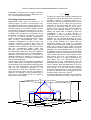
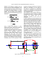
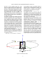
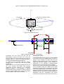
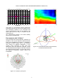
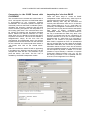
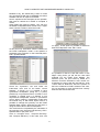
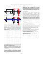
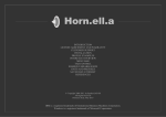
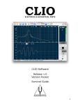
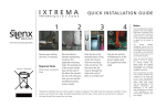
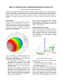
HOW TO CREATE EASE LOUDSPEAKER MODELS USING CLIO Daniele Ponteggia <[email protected]> A procedure to measure loudspeaker polar patterns using CLIOwin 7 software and thus create a model for EASE 3.0 and EASE 4.1 for Windows software is described. Magnitude models only are considered since we rely on the measurement of the horizontal and vertical polars. The measurements shall be made in a suitable anechoic space using a software controlled turntable. A simple data processing software is presented to manage the large amount of polar data and to convert the data into the EASE .xhn ASCII file format. Thus the procedure here described is valid for fairly simple loudspeakers (as example loudspeaker with polar pattern 90°x60° or 50°x40°) and for magnitude only models, i.e. EASE 3.0 or EASE 4.1 without phase. Introduction Electro-acoustics simulation softwares require the knowledge of the polar pattern of a source. In EASE 3.0 and EASE 4.1 the source is modeled as a point with a given attenuation pattern which is function of the angle of radiation. The sphere around the source is sampled in 5° angles, giving a total number of 2522 points. EASE loudspeaker models The reference system used in EASE is depicted in figure 2. The P(0,0) point is the on-axis point, the angle θ can vary between 0° and 180°, from the front to the back of the source. The angle φ can vary between 0° and 355° rotating counterclockwise from the right side of the source to the top and so on. z y φ P(0,0) Figure 1: EASE balloon Here is described a simplified procedure that requires the knowledge of the horizontal and vertical polar measurements only. This procedure is valid under certain assumptions: – the loudspeaker must present a mild asymmetry between horizontal and vertical polar patterns. An interpolation of the missing spherical polar data must be made, the procedure is valid as long as the interpolation algorithm is valid. – the model must be based on magnitude only data and not on complex data. In EASE 4.1 the point source can be described in a more detailed way using magnitude and phase polar patterns. While the interpolation of magnitude data can be accepted, the interpolation of phase data is not meaningful. θ x Figure 2: EASE reference system The attenuation respect of the on-axis value data must be known: – for every P(θ,φ) point with 5° resolution. – for every one third octave frequency band, from 100 Hz to 10 kHz. Inside EASE loudspeaker data is stored in 21 tables, one for each one third octave frequency band in the range 100 Hz – 10 kHz. Each table is 37 rows x 72 columns containing the attenuation data in respect of the polar coordinates θ and φ. The version of EASE 4.1 a second set of tables allows to store also phase data. Is it possible to consider the entire attenuation data set of a 1 HOW TO CREATE EASE LOUDSPEAKER MODELS USING CLIO loudspeaker measured with 5 degree resolution and in 21 third octave frequency bands as a 37 x 72 x 21 three dimensional matrix. f LOW = 1 t window To allow the desired low frequency threshold the loudspeaker must be placed far away enough from boundary surfaces. In practical terms, for a threshold of 100 Hz the needed reflection free time window length is 10 ms. Taking into account the travel time of the sound from the source to the receiver at a measuring distance of 6 m with a speed of sound of 340 m/s, the minimum distance from the first reflecting surface, is 3.62 m. In outdoor this means that is needed to place the loudspeaker in top of a layer structure or suspending it, in indoor means also the use of a really high ceiling, at least 7.24 m. A solution to the problem can be achieved eliminating the floor reflection using highly absorptive material placed on the ground between the source and the microphone position. This leads to a practical height for the loudspeaker, allowing measurement down to the 100 Hz range in outdoor and large closed spaces. Outdoor measurement are anyhow generally not recommendable due to the high susceptibility to noise, vibration and environmental variations as wind and heat. Measurement in large indoor spaces with anechoic floor between source and receiver can be a real alternative to the anechoic chamber, if the space dimensions are quite large, and the reverberation time is sufficiently short, polar measurements sets can performed with success. If a non-anechoic space is used to perform polar measurements it must be noted that the room reverberation time must be short enough to avoid time aliasing between successive measurements, if using an automated process the operation must be trigged to let the acoustic energy in the room to decay. A detailed and elegant explanation of the reflection free environment can be found on [5] where an Executing polar measurements Measurement setup must be arranged in an anechoic space. In order to minimize apex error and diffraction effects the distance between the microphone and the rotating loudspeaker must be sufficiently large. In the literature different values are proposed, ranging from not less than 4 m to 68 m[1]. In fact, the distance d between source point of rotation and microphone is dependent on the loudspeaker dimensions and geometry, the value of 4 m is a trade-off between measurement distance and anechoic chamber dimensions. It has been recently demonstrated[2] that, when measuring loudspeakers as point sources, the minimum measuring distance that must be achieved in order to minimize simulation errors is dependent from the distance of the acoustic center from the measurement rotation point and frequency. Given the loudspeaker geometry and the measurement distance d, either for magnitude only and complex data, there is a critical frequency threshold below which the error is bounded. A detailed explanation is beyond the scope of this document, the reader is strongly encouraged to refer to the original paper. If an anechoic room is not available is it possible to use an outdoor space or a large room together with the windowing of the measured impulse responses to get rid of the reflections[3]. The window length sets the low frequency threshold for the measurement. In brief, early reflections means a short time window hence an high low-frequency threshold, not allowing for polar measurement in the low end. The formula for the low frequency threshold is quite simple[4]: ceiling reflection receiver wall reflection R S direct path lateral reflection floor reflection W d dr H source wall reflection h ds D Figure 3: Shoe box model 2 HOW TO CREATE EASE LOUDSPEAKER MODELS USING CLIO ellipsoid of free reflections is defined. Here are reported only few practical considerations, if the room is a “shoe box” with the loudspeaker and the microphone placed as in figure 3, given the room and measurement setup dimensions is it possible to calculate the threshold frequency. Is it also possible, given the height of the loudspeaker position h, the measurement distance d and the threshold frequency to calculate the minimum room dimensions: W =2⋅ 2 c H= acoustical environment. Rotating the microphone around the loudspeaker is more prone to positioning errors. Using arrays of microphones can speed up significantly the measurement process, but is it expensive and some care must be made on the compensation of microphones and environmental differences. The loudspeaker rotation can be realized in a rather simple way using a turntable. To accelerate the measurement process a software controlled turntable has to be used, in our tests we used the OUTLINE ST-2 turntable which can be automatically controlled by CLIO via the PC parallel port. A manual turntable can be also used, but the process is quite time-consuming. Measuring only the horizontal and the vertical polars it can be quite easy to place the loudspeaker upright and rotate it around its y axis by 90° folding it on its side, at least if the loudspeaker has a regular shape. In case of trapezoidal enclosures some care must be made, the use of custom made adapters (as simple as wooden wedges) can improve the stability and the precision of the measurements. Before starting to take measurements we have to define a point of rotation of our loudspeaker. This does not necessary coincide with the geometrical center of the cabinet, and in principle must be near as possible to the acoustic center of the loudspeaker (which is not well defined point in space, since for a multi way loudspeaker it is moving with frequency). It is important to define the relationship between the rotation point and a reference point of the cabinet. In this way is it possible to include into the model the geometrical dimensions of the loudspeaker cabinet relative to the position of the point source assumed as the acoustical model of the loudspeaker itself. f LOW 2 d c f LOW 2 d 2 − 2 h 2 d d − 2 2 c 2⋅ f LOW D=d2⋅d s d s= Once a suitable space (anechoic or quasianechoic) for making measurements with the correct bandwidth is found, the next step is to decide how to collect polar measurements. In making polar measurements there are different possible approaches: rotating the microphone around a fixed loudspeaker, rotating the loudspeaker in front a fixed microphone, using an array of microphones. While in theory all these approaches are valid, again some practical considerations must be taken into account. The most used technique is to rotate the loudspeaker in front of a fixed microphone, this allows for a better precision in the positioning of the microphoneloudspeaker group, this also guarantee a stable ROTATION AXIS d zrp ROTATION POINT MICROPHONE yrp POINT OF REFERENCE SIDE VIEW Figure 4: Model dimensions – horizontal setup 3 FRONT VIEW HOW TO CREATE EASE LOUDSPEAKER MODELS USING CLIO We call yrp as the distance along the y axis between the reference point and the rotation point. Also is of great importance the relative height between microphone and cabinet reference point, let's call zrp this distance between the cabinet reference point and the microphone axis along z. The reference point, the point of rotation and cabinet dimensions must be annotated in a detailed way in order to create a correct model of the loudspeaker (see figure 4). It is suggested to take as a reference point a vertex or the center of an edge of the cabinet. The distance d between the rotation axis ad the microphone membrane must be recorded to later refer the measurement to the 1 W/1 m standard. It is not necessary to feed the speaker under test with a power that produce the 1 W/1 m sound pressure level at the measuring distance d. This can lead to overpowering the speaker, pushing towards the non linearity zone of the measurement system and the speaker itself. Is it recommendable to use moderate output levels, reaching the best trade-off between level and measurement signal to noise ratio. It is possible to modify the levels to specific on axis values when importing the model in EASE, or shift the levels of a given amount of dB into the data processing software. If the power feed to speaker is known, using d and the nominal power W applied is it possible to calculate the 1 W/1 m on axis response. Since the source is modeled as a point source, its 1 W/1 m on axis level is given by: If the measure is made in an anechoic space no time windowing is needed, elsewhere the tail of the response must be windowed to eliminate the sound reflections. If needed set the window in CLIO with start t=0 and stop time as required. Horizontal polar setup To measure only the horizontal polar the loudspeaker must be placed on the turntable in upright position. In case of small loudspeaker it can be required to use a speaker stand to raise the box from the turntable in order to avoid reflections from the surface of the turntable itself. The speaker must be initially placed on the turntable rotated around the z axis by 180°, facing the back of the enclosure to the microphone, as showed in figure 5. In this way the clockwise rotation of the speaker is equivalent to a complete counterclockwise apparent rotation of the microphone around the speaker itself. The measurement process can be automated with CLIOwin auto-save and external hardware control features. Be sure to open the external hardware control window, set the proper LPT port for the turntable and activate “link to measurement”. In order to control the turntable this window must remain open during the measurement procedure. Open the “MLS & LogChirp Analysis” module, check the “auto-save” and “measure in a loop” icons (see figure 6). The auto-save settings are shown in figure 7. The auto-save settings window is available from the “file” menu. Use binary format, choose a folder to store the measurements. Set a L 1W /1m=L d 20⋅log d −10⋅log W z Microphone Microphone apparent rotation x y 0° Turntable rotation Figure 5: Horizontal polar setup 4 HOW TO CREATE EASE LOUDSPEAKER MODELS USING CLIO Autosave & Measure in a Loop Turntable Control Activated Figure 6: CLIOwin autosave and turntable control Binary Format Angular Settings Filename & Folder Figure 7: Autosave settings Figure 8: Folder with saved .mls data 5 HOW TO CREATE EASE LOUDSPEAKER MODELS USING CLIO x Microphone Microphone apparent rotation z 0° y Turntable rotation Figure 9: Vertical polar setup ROTATION AXIS ROTATION POINT MICROPHONE yrp POINT OF REFERENCE SIDE VIEW zrp FRONT VIEW Figure 10: Model dimensions – vertical setup convenient root file name, the file will be automatically named by CLIO as <root file name>+angle, the root file name can be called for example: “DUT_H”, where H denotes that this is the set of horizontal polar measurements. To gather the full horizontal polar the angular settings must be: start=-180, increment=5, total number=72. At this point the set of polar measurement can be run. The process will takes few minutes (depending on MLS settings). If an automated rotating turntable is not available, a manual measure-rotate-save procedure must be adopted. Figure 8 shows a folder with a series of file saved into the CLIOwin polar auto-save format. Vertical polar setup The loudspeaker must be placed on the turntable on its side, inclined 90° towards right as shown in figure 9. The measure set must start with the speaker giving its back side to the microphone. Again the clockwise rotation of the speaker is equivalent to an apparent counterclockwise rotation of the microphone around the speaker. Care must be spent in positioning the loudspeaker on the turntable, letting the rotation axis to pass through the rotation point, as indicated in figure 10. This can be quite tricky since it means to move the relative turntable to microphone height. Usually the easiest way is to move the microphone height, the assumption that the microphone and source rotation point positions on the room are fixed is no 6 HOW TO CREATE EASE LOUDSPEAKER MODELS USING CLIO Audiomatica LogChirp - Impulse Response 21-11-2005 14.52.00 0.20 CLIO Pa 0.16 0.12 0.080 0.040 0.00 -0.040 -0.080 -0.12 -0.16 -0.20 0.00 1.1 2.3 3.4 4.6 5.7 6.9 8.0 9.1 ms 10 11 Figure 11: An example of shorter reflection free response Figure 13: CLIOwin 7 directivity color-map more valid, in a non-anechoic space a previously windowed response can be no more reflection free. The windowing needed by the horizontal and vertical measurement sets can be different, the worst case must be used to window all the measurements. The measurement process is the same already seen for the horizontal polar. z 175 -180 y 175 -180 Data analysis with CLIOwin 7 Once horizontal and vertical data are collected, is it possible to look at the dispersion patterns thanks to the new possibilities of CLIOwin 7 “Waterfall & Directivity” module. Please refer to the CLIOwin user manual for detailed explanation of this module. Some examples of polar plots and attenuation maps are reported in figures 12 and 13. Remember that the angles of the data collected are those indicated in figure 14, since they refer to the apparent microphone rotation around the loudspeaker. 0 x microphone position Figure 14: Horizontal and vertical angle reference, as measured with autosave Figure 12: CLIOwin 7 polar plots 7 HOW TO CREATE EASE LOUDSPEAKER MODELS USING CLIO Conversion to the EASE format with CLIO2EASE Importing the *.xhn into EASE There are three ways to create an EASE loudspeaker model: manual entry, ASCII import or impulse responses import (only for EASE 4.1). Manual entering even only the horizontal and vertical polar attenuation data can be a tiresome task, it means filling 21 x 37 x 4 = 3108 cells. It is practically unmanageable. Nevertheless it can be quite instructive to play around with the attenuation data tables to deeply understand EASE loudspeaker models. The import ASCII feature is the way to automatize the data entry task, a file structure is indicated and can be compiled by an external software such as the converter software described later on. ASCII files to be imported by EASE 4.1 can contain or not phase information. With EASE is supplied an Excel .xls spreadsheet that can be filled with the same data as the EASE attenuation data table, with a minimum of possible automation thanks to Excel. At the end of the data entry the spreadsheet create an .xhn ASCII file that can be imported by EASE. In EASE 4.1 is it also possible to import directly a collection of impulse responses in different formats: .wav, .tim, .frq. The file naming convention is not compatible with the CLIO one, so this approach is not working. The conversion from horizontal and vertical sets of CLIO .mls impulse responses to EASE data tables is accomplished by the conversion software CLIO2EASE. The conversion software remaps the measured polars into the EASE coordinate system, calculates the frequency response and the third octave smoothing and perform the interpolation of the missing polar data. The measurements must be carried out following the procedure indicated before. Please note that the software is in early alpha stage, but it is already functional and allows to perform conversions. The use of the software is straightforward, simply fill the form with the manufacturer and loudspeaker name, the nominal impedance and choose two files from the data sets for the horizontal and vertical polar data saved in .mls format, then click on the “Create ASCII” button. After few seconds the ASCII file will be appearing in the Memo box. Select the text and copy it to the notepad then save with the *.xhn extension or just press the button “.xhn Save”. The file *.xhn is readable by the EASE loudspeaker module. Figure 15: CLIO2EASE converter screenshot 8 HOW TO CREATE EASE LOUDSPEAKER MODELS USING CLIO Needles to say, the easiest way is then to create the .xhn ASCII file with the CLIO2EASE conversion software and then to import it into EASE. Here is reported a brief examples of the operation that must be carried out in EASE to complete a model. Open EASE and import the ASCII “.xhn” file from the EASE Loudspeaker Base module: File > Import ASCII. Choose a folder to store the model: on “Apply”. At this point is it possible, if desired to draw the loudspeaker case: Edit > Case. At this point only attenuation data are loaded into the EASE loudspeaker model. If the speaker is supposed to be symmetric on the horizontal plane: Edit > Speaker Model. Is it possible to draw the case with faces or with edges. Using faces you will see the case solid rendered into the EASE Eyes Module. The reference point, the point used by EASE as a reference for all the simulation is 0,0,0 unless it is changed by the user inside the case edit by: Tools > Move Point of Reference. Since the position of the Point of Reference POR is relative to the case, it is not necessary to move the POR if we correctly draw the case around the POR. Check the “Symmetric” box and follow the instructions, then click on the button “Check Speaker”. In EASE 3.0 it is possible to have symmetrical loudspeaker (along the y-z plane) placed only in symmetrical rooms, In EASE 4.1 this constraint is relaxed and it is allowed to use asymmetrical loudspeaker models in symmetrical rooms. When creating a loudspeaker model with the manual entry or with ASCII import mode is it possible to manage the symmetry into the EASE Speaker Base module, discarding an half polar or using the mean value of the two half polars. The model must be completed by the calculation of the coverage cone, directivity and efficiency: Edit > Speaker Data or just press <F4>. Click on “Compute Cone”, “Compute Directivity” and “Compute Efficiency” in this order, then click 9 HOW TO CREATE EASE LOUDSPEAKER MODELS USING CLIO In the loudspeaker measurement setup is: of this example, the model as authorized. This guarantees that a loudspeaker model is approved by the manufacturer. More information on the EASE Loudspeaker base module can be found on EASE manual and documentation, another good source of information is the website www.auralisation.de. HORIZONTAL POLAR SETUP ROTATION AXIS d ROTATION POINT zrp Conclusions This work is a first attempt to simplify the measurement-model-simulate process with CLIOwin and EASE. It currently allows only the use of horizontal and vertical polar data sets to create magnitude only models. We are currently carrying on experimentation with full sphere automated measurement. In the near future a new version of the software will perform data conversion of full sphere measurement sets to realize complex data (magnitude+phase) models. MICROPHONE yrp SIDE VIEW FRONT VIEW VERTICAL POLAR SETUP ROTATION AXIS d ROTATION POINT MICROPHONE yrp SIDE VIEW Bibliography zrp [1] Electro-Acoustic Testing Company, “What does it take to measure a loudspeaker?”, http://www.etcinc.us/Parameters.htm FRONT VIEW Where the cabinet dimensions are H=30 cm W=19 cm and D=16, the rotation point (called Point of Reference POR in EASE) position relative to the edge of the case, as in figure are yrp=8 cm and zrp=15 cm. Assuming that the 0,0,0 is the position of the POR the loudspeaker case design is straightforward: [2] S.Feistel, W.Ahnert, “The Significance of Phase Data for the Acoustic Prediction of Combinations of Sound Sources”, AES 119th Convention – New York, 2005 October 7-10. [3] F.Seidel, H.Staffeldt, “Frequency and Angular Resolution for Measuring, Presenting, and Predicting Loudspeaker Polar Data”, JAES, Vol. 44, No. 7/8, 1996 July/August. [4] Audiomatica, “CLIOwin 7 User's Manual”, http://www.cliowin.com/ [5] C.Struck, S.Temme, “Simulated Free Field Measurements”, JAES, Vol. 42, No. 6, 1994 June. The model is complete and can be saved to be used into the simulation program. In figure an example of the loudspeaker model used into a room for acoustical coverage prediction is illustrated. Once a loudspeaker model is created, the model is saved as unauthorized model, to authorize the model is it necessary to contact directly ADA and ask for the Authorization software that mark your 10