1
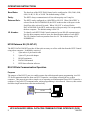
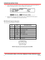
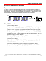
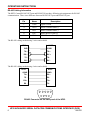
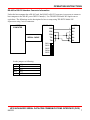
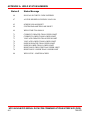
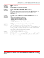
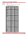
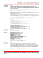
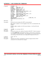
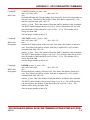
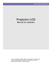
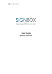
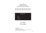
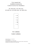
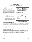
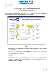
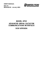
USER'S MANUAL 990-331 REVISION B: January 2002 MODEL HF25 ADVANCED SERIAL DATACOM COMMUNICATIONS INTERFACE DOS VERSION Copyright © 1997, 2002 Unitek Miyachi Corporation The engineering designs, drawings and data contained herein are the proprietary work of UNITEK MIYACHI CORPORATION and may not be reproduced, copied, exhibited or otherwise used without the written authorization of UNITEK MIYACHI CORPORATION. Unitek Miyachi 1820 South Myrtle Avenue P.O. Box 5033 Monrovia, CA 91017-7133 Telephone: (626) 303-5676 FAX: (626) 358-8048 e-mail: [email protected] Printed in the United States of America. REVISION RECORD Revision EO Date Basis of Revision A -- 2/97 Original Release. B 19146 01/02 Updated data and format. HF25 ADVANCED SERIAL DATACOM COMMUNICATIONS INTERFACE (DOS) ii 990-331 OPERATING INSTRUCTIONS Table of Contents Page Section 1. General Description ...............................................................................................................1 HF25 Serial Communication ...............................................................................................................1 HF25 Communication Options ............................................................................................................1 HF25 Datacom Kit (10-347-01) ..........................................................................................................2 RS-232 Data Communication Operation .............................................................................................2 Purpose .........................................................................................................................................2 Making RS-232 Connections .......................................................................................................3 RS-232 Serial Connector Information ..........................................................................................4 RS-485 Data Communication Operation .............................................................................................5 Purpose ..........................................................................................................................................5 Making RS-485 Connections .......................................................................................................5 RS-485 Cabling Information ........................................................................................................6 RS-485 To RS-232 Interface Converter Information ...................................................................7 Section 2. Remote Data Collection .........................................................................................................8 Weld Report .........................................................................................................................................8 Example of a Weld Report ..................................................................................................................8 Simple Data Collection ........................................................................................................................9 Examples of Remote Data Collection Commands ..............................................................................9 Section 3. Remote Programming ..........................................................................................................10 Command Summary ..........................................................................................................................10 Examples of Remote Programming Commands ................................................................................11 Appendix A. Weld Status Messages .................................................................................................. A-1 Appendix B. Host Originated Commands .........................................................................................B-1 Appendix C. HF25 Originated Commands .......................................................................................C-1 iii Section 1. General Description HF25 Serial Communication The purpose of the HF25 Control serial port is to enable remote data collection and remote programming via a serial communications line between the HF25 Control(s) and a serial data collecting device or host computer. The HF25 Control has two ways of reporting weld information or programming remotely - using RS-232 and RS-485. The RS-232 communication provides a simple way of reporting weld information from a HF25 Control to a computer. To use the RS-232 communication, refer to RS-232 Data Communication Operation. The RS-485 communication provides a way of collect weld reports from one or more HF25 Controls using one host computer. To use the RS-485 communication, refer to RS-485 Data Communication Operation. There is no difference between the operations of RS-232 communication and RS-485 communication other than that RS-485 can be daisychained and RS-232 can not. RS-232 COMMUNICATION RS-232 COMPUTER RS-485 COMMUNICATION UP TO 30 HF25's RS-485 TERMINATOR OUT IN OUT IN OUT IN OUT IN OUT IN RS-485 / RS-232 CONVERTER HF25 HF25 HF25 HF25 HF25 HOST COMPUTER HF25 Communication Options To establish communication through the Serial Port connector, the Communication options should be set to match the communication configuration of the host computer. The communication options are set from the HF25 COMMUNICATION menu. HF25 ADVANCED SERIAL DATACOM COMMUNICATIONS INTERFACE (DOS) 990-331 1 OPERATING INSTRUCTIONS Baud Rates: The baud rate of the HF25 Weld Control can be configured at 1200, 2400, 4800, 9600, 14.4K, 19.2K, or 28.8K. The default setting is 9600. Parity: The HF25 always communicates in 8 bits with no parity and 1 stop bit. Datacom Role: The HF25 can be configured as a MASTER or SLAVE. When “MASTER” is selected for the DATACOM ROLE, the HF25 sends out the weld report via the Serial Port after each weld is made. When “SLAVE” is selected for the DATACOM ROLE, the HF25 sends out the weld report only if it is requested by the host computer. The default setting is SLAVE. I.D. Number: To identify each HF25 Weld Control connected to one RS-485 communication line, the host computer needs to know the identification number of each HF25. The I.D. Number can be any number from 0 to 99. The default setting of I.D. NUMBER is 1. HF25 Datacom Kit (10-347-01) The HF25 DATACOM KIT provides all the tools necessary to collect weld data from the HF25 Control using a host computer. It should be consist of: 1. 9 pin male to 9 pin female cable 2. 9 pin to 25 pin serial adapter. 3. RS-485 terminator. 4. DATACOM manual 5. HF25 data collection software. RS-232 Data Communication Operation Purpose The purpose of the RS-232 port is to enable remote data collection and remote programming via a RS232 serial communication line from one HF25 Control to a serial data collecting device or host computer. This protocol provides a simple way of reporting weld information from a HF25 Control to a computer. Using a RS-232 communication, remote programming is also allowed. However, this section describes simple remote data collection method only. RS-232 COMPUTER HF25 ADVANCED SERIAL DATACOM COMMUNICATIONS INTERFACE (DOS) 2 990-331 OPERATING INSTRUCTIONS Making RS-232 Connections 1 Turn off the HF25 Control. 2 Connect the 9 pin to 9 pin cable to RS-232 connector on the rear panel of the HF25 Control to the RS232 connector on a host computer. Use 9 pin to 25 pin adapter if necessary. The cable and adapter are part of the HF25 DATACOM kit. 3 Insert DATACOM diskette to the floppy drive of the computer. The data collection software included in HF25 DATACOM kit provides a simple way of collecting weld reports from a HF25. 4 Type INSTALL to install the data collection software. Follow the screen instructions. 5 After the installation is complete, type DATACOM from DOS prompt. 6 Select SETUP and set COM port to serial port to which the serial cable is connected. Set baud rate to 9600 baud. Set HF25 Communication Role to “SLAVE”. 7 Turn on the HF25 Weld Head Control. HF25 ADVANCED SERIAL DATACOM COMMUNICATIONS INTERFACE (DOS) 990-331 3 OPERATING INSTRUCTIONS 8 Set the baud rate of the HF25 Control to 9600. The HF25 serial communication baud rate setting is listed under the HF25 Control COMMUNICATIONS menu. 9 Set the ROLE option in the HF25Weld Head Control COMMUNICATIONS menu to “SLAVE”. I.D. NUMBER does not matter at this time. RS-232 Serial Connector Information The serial port pin assignment is as follows: Pin Name Description (DCE) 1 2 TXD RS-232 Transmit Data 3 RXD RS-232 Receive Data 4 DSR Data Set Ready 5 SGND Signal Ground 6 DTR Data Terminal Ready 7 CTS Clear to Send 8 RTS Request to Send 9 RI Ring Indicator 5 4 9 3 8 2 7 1 6 RS-232 Connector on the back panel of the HF25. HF25 ADVANCED SERIAL DATACOM COMMUNICATIONS INTERFACE (DOS) 4 990-331 OPERATING INSTRUCTIONS RS-485 Data Communication Operation Purpose The purpose of the RS-485 ports are to enable remote data collection and remote programming via a half-duplex multi-drop RS-485 communications line between HF25s and a serial data collecting device or host computer. The protocol will be implemented using printable ASCII characters to allow ease of protocol translation, comprehension, and debugging in control systems development. UP TO 30 HF25's RS-485 TERMINATOR OUT IN OUT IN OUT IN OUT IN OUT IN RS-485 / RS-232 CONVERTER HF25 HF25 HF25 HF25 HF25 HOST COMPUTER Making RS-485 Connections 1 Turn off the HF25 Control(s). 2 Connect the serial connector on a host computer to RS-232/RS-485 converter using 9 pin to 9 pin cable provided with HF25 DATACOM kit. Use 9 pin to 25 pin adapter if necessary. 3 Connect the RS-485 IN connector on the rear panel of each HF25 Weld Head Control to the RS-485 connector on the RS-485 to RS-232 converter. There is no standard cable for RS-485; therefore, special cabling is required. Refer to the cabling information in RS-485 CABLING INFORMATION section. If the host computer have a RS-485 communication port, there is no need to use the RS-232 to RS-485 converter. 4 Daisy-chain the HF25 Controls if more than one HF25 Controls are to be connected. Use standard 9 pin female to 9 pin female serial cables. 5 Turn on the HF25 Control(s). 6 Set the baud rate of the HF25 Control(s) and the host computer to the same baud rate. The HF25 serial communication baud rate setting is listed under the HF25 Weld Head Control COMMUNICATIONS menu. 7 Set the ROLE option in the HF25 Control COMMUNICATIONS menu to “SLAVE”. 8 Set the unit ID number in the HF25 Control COMMUNICATIONS menu. Each HF25 unit should have its own unique ID number to be identified by the host computer. HF25 ADVANCED SERIAL DATACOM COMMUNICATIONS INTERFACE (DOS) 990-331 5 OPERATING INSTRUCTIONS RS-485 Cabling Information The HF25 Control RS-485 OUT port and RS-485 IN port have following pin assignments for RS-485 communication. There is no difference between RS-485 OUT port and RS-485 IN port. Pin Name Description 1 GND 4 TXD + RS485 Transmit Data (+) 5 TXD RS485 Transmit Data (-) 8 RX + RS485 Receive Data (+) 9 RX RS485 Receive Data () Signal Ground The RS-485 cabling method using 2 wires and a shield: HF25 GND TX + RX + HOST 1 CGND 4 TX + 8 RX + TX - 5 TX - RX - 9 RX - The RS-485 cabling method using 4 wires and a shield: HF25 CGND TX + HOST 1 CGND 4 RX + TX - 5 RX - RX + 8 TX + RX - 9 TX - 5 4 9 3 8 2 7 1 6 RS-485 Connector on the back panel of the HF25. HF25 ADVANCED SERIAL DATACOM COMMUNICATIONS INTERFACE (DOS) 6 990-331 OPERATING INSTRUCTIONS RS-485 to RS-232 Interface Converter Information Unless the host computer has a RS-485 card, the RS-485 to RS-232 converter is necessary to connect a host computer to the RS-485 port of HF25 Control(s). Use TELEBYTE Model 285 Superverter or equivalent. The followings are the description for how to setup using TELBYTE Model 285 Superverter using 3 wires connection. HOST COMPUTER MODEL 285 SERIAL CABLE HF25 GND 1 GND RX - 4 TX+ RX+ 5 TX- TX - 8 RX+ TX+ 9 RX- SW1 SW2 SW3 SW4 SW5 Set the jumpers as following: sw1 sw2 sw3 sw4 sw5 ON OFF ON ON OFF HF25 ADVANCED SERIAL DATACOM COMMUNICATIONS INTERFACE (DOS) 990-331 7 OPERATING INSTRUCTIONS Section 2. Remote Data Collection The HF25 data communication protocol includes the capability of collecting basic weld information for each individual weld. The HF25 stores weld information for the last 3000 welds. Weld Report When DATACOM ROLE of the HF25 Control is set to “MASTER”, the HF25 sends out the weld report via the serial ports after each weld is made. When DATACOM ROLE of the HF25 Control is set to “SLAVE”, the HF25 sends out the weld report only if it is requested by the host computer. With “SLAVE” setting, the host computer should periodically poll the HF25 to collect the weld data before 3000 welds are reached. Otherwise, data over-run occurs and weld data will be lost starting with the oldest data. The following information is included in the HF25 weld report. 1. The schedule number of the weld, 2. The average current of 1st weld pulse, 3. The average voltage of 1st weld pulse, 4. The % control capacity needed to reach the 1st weld pulse, 5. The average current of 2nd weld pulse, 6. The average voltage of 2nd weld pulse, 7. The % control capacity needed to reach the 2nd weld pulse, 8. The status of the weld. Example of a Weld Report 3,205,217,12,513,452,22,0 The above weld report represents the following information: 1. Schedule number: 3 2. Average current of the 1st weld pulse: 205 A 3. Average voltage of the 1st weld pulse: 217 mV 4. % control capacity of the 1st weld pulse: 12 % 5. Average current of the 2nd weld pulse: 513 A 6. Average voltage of the 2nd weld pulse: 452 mV 7. % control capacity of the 2nd weld pulse: 22 % 8. Status of the weld: 0 (GOOD) For the list of the weld status codes, see Appendix A, Weld Status Numbers. HF25 ADVANCED SERIAL DATACOM COMMUNICATIONS INTERFACE (DOS) 8 990-331 OPERATING INSTRUCTIONS Simple Data Collection In order to do the simple data collection, the host only needs to send #ID REPORT NEW number command. ID is the identification number of the HF25. number is a number greater than the number of welds made since the last data collection. Then the HF25 then send all the weld reports since the last data collection and erases all the weld data sent from the weld data buffer. The host should parse the weld report. The weld reports are separated with <crlf>. The fields within the report are separated with a comma. See SECTION 3 & 4 for additional remote data collection commends. Examples of Remote Data Collection Commands #1 REPORT OLD 10 <crlf><lf> Host is requesting the HF25 with id #1 to send 10 weld reports from the accumulated weld reports. The weld data counter in the HF25 is decremented by 10. The corresponding HF25 with id #1 will response with: #1 REPORT 10 <crlf> 3,205,217,12,513,452,22,0 <crlf>weld report #1 3,211,216,13,511,451,22,0 <crlf> weld report #2 3,202,212,14,512,453,22,0 <crlf> weld report #3 3,203,217,12,513,456,22,0 <crlf> weld report #4 3,207,218,11,513,457,22,0 <crlf> weld report #5 3,206,222,12,514,458,22,0 <crlf> weld report #6 3,205,214,14,513,461,22,0 <crlf> weld report #7 3,208,212,13,512,439,22,0 <crlf> weld report #8 3,209,218,15,515,451,22,0 <crlf> weld report #9 3,202,218,16,512,455,22,0 <crlf> weld report #10 <lf> #1 REPORT NEW 1 <crlf><lf> Host is requesting the HF25 with id number 1 to send the latest weld reports. The weld data counter is reset to 0. The corresponding HF25 with id #1 will response with #1 REPORT 1 <crlf> 3,205,217,12,513,452,22,0 <crlf>weld report #1 <lf> HF25 ADVANCED SERIAL DATACOM COMMUNICATIONS INTERFACE (DOS) 990-331 9 OPERATING INSTRUCTIONS Section 3. Remote Programming The portions of the protocol that include the physical layer (hardware electrical interconnect), the link layer (framing, data encoding, duplex control), the network layer (source-destination identification) and the transport layer (packet framing & token control) are implemented in the HF25. The HF25 must always be in the Slave Mode to send data in a polled request-response synchronous operation utilizing a packetized token-passing-like control & accepting input commands. The multi-drop signal synchronization control utilizing a token-passing-like algorithm uses the unit identification portion of the command screen as the token, which is the pound sign (#) followed by the unit ID number. When no information is being passed, the host passes an empty token, which is a packet consisting of the token followed by the end of packet sequence (<crlf><lf>). If the HF25 has a message to return, it sends the message along with the token to the host. Otherwise, if the HF25 has no message to return, it returns an empty token. A message consists of any command and its parameters or other data accompanying the command. Each token-message packet must conclude with an end of packet sequence. The HF25 ignores any packet beginning with a unit ID that does not match it's programmed value, up to the point that an idle line is detected. Thus, at least one character time of idle line is required between packets to wake up all HF25 Weld Controls on the communication line in order to recognize any subsequent packet that may be addressed to them. Command Summary Packet format: #ID KEYWORD parameters <crlf><lf> unit identification & token#ID (ID is any number from 0 to 255, must be left-justified or zeropadded to left) command keywords:BOLD variable to be replaced by literal:italics required parameters:{enclosed in braces} (one required and only one parameter allowed) optional parameters:[enclosed in brackets] (zero or more allowed) required/optional parameters:{[enclosed in braces and brackets]} (one or more allowed) choice of parameters:separated by vertical bar "|" indicates one OR another of choices presented. range of parameters:low_end - high_end (separated by hyphen) end of parameter line:<crlf>(carriage return followed by newline) end of packet: <lf>(new line - must be preceded by the end of parameter line <crlf>) Each component (token, keyword, and parameters) will and must be separated by one or more nonprinting characters (spaces or tabs) except the end of packet <lf> must follow the end of parameter line <crlf> immediately. Non-printing characters immediately preceding the end of parameter line <crlf> are ignored. HF25 ADVANCED SERIAL DATACOM COMMUNICATIONS INTERFACE (DOS) 10 990-331 OPERATING INSTRUCTIONS Examples Of Remote Programming Commands #1 LOAD 10 <crlf><lf> Host is requesting the HF25 that has ID #1 to load schedule #10. The corresponding HF25 with ID #1 will response with #1 <crlf><lf> #1 COUNTER TOTAL <crlf><lf> Host is requesting the HF25 with ID #1 to send the total weld counter. The corresponding HF25 with ID #1 will respond with #1 COUNTER ####### <crlf><lf>where ####### is the current total weld counter. #5 SCHEDULE <crlf><lf> Host is requesting the HF25 with ID #5 to send the current schedule number selected. The corresponding HF25 with ID #5 will respond with #5 SCHEDULE ##<crlf><lf>where ## is the current schedule number of HF25 #5 SCHEDULE READ<crlf><lf> Host is requesting the HF25 with ID #5 to send the current schedule information. The corresponding HF25 with ID #5 will respond with #5SCHEDULE ##<crlf>where ## is the current schedule number of HF25 FEEDBACK1 ##<crlf>where ## is the feedback of pulse 1 FEEDBACK2 ## <crlf>where ## is the feedback of pulse 2 SQUEEZE ### <crlf>where ### is the squeeze time in ms UP1 ### <crlf> where ### is the upslope time of pulse 1 in 100 μs WELD1 ### <crlf>where ### is the weld time of pulse 1 in 100 μs DOWN1 ### <crlf>where ### is the downslope time of pulse 1 in 100 μs COOL ### <crlf> where ### is the cool time in 100 μs UP2 ### <crlf> where ### is the upslope time of pulse 2 in 100 μs WELD2 ### <crlf>where ### is the weld time of pulse 2 in 100 μs DOWN2 ### <crlf>where ### is the downslope time of pulse 2 in 100 μs HOLD ### <crlf>where ### is the hold time in ms ENG1 ### <crlf> where ### is the energy of pulse 1 ENG2 ### <crlf> where ### is the energy of pulse 2 <lf> HF25 ADVANCED SERIAL DATACOM COMMUNICATIONS INTERFACE (DOS) 990-331 11 APPENDIX A WELD STATUS MESSAGES The last field in the report packet represents the status of the weld made. Status numbers and definitions are listed below. Status # Status Message 0 1 2 3 4 5 6 7 8 GOOD CHECK CONTROL SIGNALS INPUT STATUS CHECK INPUT SWITCH STATUS FIRING SWITCH BEFORE FOOT SWITCH EMERGENCY STOP ON CONTROL SIGNALS INPUT POWER TRANSISTOR OVERHEATED EMERGENCY STOP - OPERATOR ACTIVATED FIRING SWITCH DIDN'T CLOSE IN 10 SECOND WELD TRANSFORMER OVERHEATED 10 11 12 13 14 15 16 17 VOLTAGE SELECTION PLUG IS MISSING INHIBIT CONTROL SIGNALS ACTIVATED LOW BATTERY NO CURRENT READING NO VOLTAGE READING LOAD RESISTANCE TOO HIGH NO WELD TRANSFORMER DETECTED WELD SWITCH IN NO WELD POSITION 19 20 21 CALIBRATION RESET TO DEFAULT LOWER LIMIT GREATER THAN UPPER LIMIT COOL TIME ADDED FOR DIFFERENT FEEDBACK 23 SYSTEM & SCHEDULE RESET TO DEFAULTS 26 SAFE ENERGY LIMIT REACHED 31 32 33 34 UPSLOPE REQUIRED FOR LOWER LIMIT INPUT TOO LARGE INPUT TOO SMALL PRESS RUN BEFORE WELDING 39 ACCESS DENIED! SYSTEM SECURITY ON HF25 ADVANCED SERIAL DATACOM COMMUNICATIONS INTERFACE (DOS) 990-331 A-1 APPENDIX A: WELD STATUS NUMBERS Status # Status Message 40 ILLEGAL SECURITY CODE ENTERED 47 ACCESS DENIED! SCHEDULE LOCK ON 65 66 SCHEDULES ARE RESET SYSTEM PARAMETERS ARE RESET 69 WELD TIME TOO SMALL 71 72 73 74 75 76 77 78 CURRENT GREATER THAN UPPER LIMIT CURRENT LOWER THAN LOWER LIMIT VOLTAGE GREATER THAN UPPER LIMIT VOLTAGE LOWER THAN LOWER LIMIT POWER GREATER THAN UPPER LIMIT POWER LOWER THAN LOWER LIMIT RESISTANCE GREATER THAN UPPER LIMIT RESISTANCE LOWER THAN LOWER LIMIT 80 WELD STOP - LIMIT REACHED HF25 ADVANCED SERIAL DATACOM COMMUNICATIONS INTERFACE (DOS) A-2 990-331 APPENDIX B: HOST ORIGINATED COMMANDS These are the commands sent by the host computer, via RS-485 or RS-232 to an HF25. Command: HF25 state: Description: STATUS <crlf><lf> Any Requests the HF25 to report the status of the weld data buffer. HF25 returns STATUS with either “OK” or “OVERRUN.” Command: HF25 state: Description: COUNT <crlf><lf> Any Requests the HF25 to report the number of weld data accumulated since the last data collection. HF25 returns the COUNT even if there is no weld data available. Command: HF25 state: Description: LOAD schedule_number <crlf><lf> RUN state Selects the schedule_number as the currently loaded schedule. schedule_number may be any number from 0 to 127. There must be a space between LOAD and schedule_number. Command: HF25 state: Description: SCHEDULE <crlf><lf> Any Requests the HF25 to return the currently selected schedule number. command: HF25 state: Description: COUNTER {TOTAL | HIGH | LOW | GOOD }<crlf><lf> Any Requests the HF25 to return the HF25 weld counter contents. TOTAL returns the total number of weld counter. HIGH returns the out of limits high counter. LOW returns the out of limits low counter. GOOD returns the within limits counter. Command: HF25 state: Description: REPORT { OLD | NEW } number <crlf><lf> Any Requests the HF25 to send the weld report. OLD: requests to send the number of oldest weld reports since the last data collection. The reported weld data will be erased. NEW: requests to send the number of newest weld reports. All the weld data will be erased after reported. number: the number of weld data to be sent. HF25 ADVANCED SERIAL DATACOM COMMUNICATIONS INTERFACE (DOS) 990-331 B-1 APPENDIX B: HOST ORIGINATED COMMANDS If the number is greater than the number of weld data in the buffer, less than the number of weld data will be sent. There must be a space between two fields. HF25 ADVANCED SERIAL DATACOM COMMUNICATIONS INTERFACE (DOS) B-2 990-331 APPENDIX B: HOST ORIGINATED COMMANDS Command: HF25 state: Description: ERASE <crlf><lf> Any Requests the HF25 to erase all the weld reports. Command: HF25 State: STATE {READ | RUN | PROGRAM | MENU } <crlf><lf> Any Description:Commands sentry to identify its current state ("READ" keyword, see STATE under HF25 Originated Commands, or go to either RUN state or PROGRAM state. command: HF25 State: description: SECURITY {OFF | SCHEDULE | SYSTEM | CALIBRATION} <crlf><lf> Any Allows control of the Sentry security mode. “OFF” sets all security status HF25 to “OFF”. “SCHEDULE” sets the schedule lock to “ON.” “SYSTEM” sets the system lock to “ON.” “CALIBRATION” sets the calibration lock to “ON.” command: HF25 State: description: COPY {from_schedule_number} {to_schedule_number} <crlf><lf> Any state Allows one schedule to be copied to another schedule number. From_schedule_number and to_schedule_number may be any number from 0 to 127. Copying a schedule to itself has no effect other than to invoke a schedule printout when "PRINT SCHEDULES/PROGRAMS" is enabled. command: HF25 State: description: SCREEN { TEXT | ATTRIBUTE } <crlf><lf> Any state Requests the HF25 to send screen dump. If TEXT is specified, the HF25 sends 320 bytes of the text screen dump. If ATTRIBUTE is specified, the HF25 sends 320 bytes of attribute screen dump. HF25 ADVANCED SERIAL DATACOM COMMUNICATIONS INTERFACE (DOS) 990-331 B-3 APPENDIX B: HOST ORIGINATED COMMANDS Command: HF25 state: Description: KEY key_code <crlf><lf> Any Process the key_code as if it was pressed from the front panel. The following are the key_codes: Key Dec Hex SQUEEZE 58 3A UP 1 59 3B WELD 1 60 3C DOWN 1 61 3D COOL 62 3E UP 2 63 3F WELD 2 64 40 DOWN 2 65 41 HOLD 66 42 UP 30 1E DOWN 31 1F 0 48 30 1 49 31 2 50 32 3 51 33 4 52 34 5 53 35 6 54 36 7 55 37 8 56 38 9 57 39 PERIOD 46 2E KA 4 04 V 5 05 KW 6 06 RUN 15 0F MENU 23 17 ENERGY 10 0A HF25 ADVANCED SERIAL DATACOM COMMUNICATIONS INTERFACE (DOS) B-4 990-331 APPENDIX B: HOST ORIGINATED COMMANDS PEAK 3 03 HF25 ADVANCED SERIAL DATACOM COMMUNICATIONS INTERFACE (DOS) 990-331 B-5 APPENDIX B: HOST ORIGINATED COMMANDS command: HF25 State: description: command: HF25 State: description: ALARM {READ | CLEAR | SET error_number | DISPLAY alarm_message_string} <crlf><lf> Any Provides access to the HF25 alarm logic. When used with the "READ" keyword, the current error condition value is returned. See Appendix A. for list of alarm messages. When the "CLEAR" keyword is used, all alarm conditions are canceled. When the "SET" keyword is used, the host may invoke an error identified by error_number. When the "DISPLAY" keyword is used, an error condition can be created with any message desired. The length of the error message must be limited to 40 characters or less. No help message will be available in connection with this created error message. SCHEDULE {READ | SET} <crlf> parameter_name value [<crlf> parameter_name value <crlf> ] <lf> Any except while welding Provides control over the HF25 schedule parameters. When used with the "READ" keyword, all parameters pertaining to the currently loaded schedule are returned (see SCHEDULE under HF25 ORIGINATED COMMANDS). When the "SET" keyword is used, the host may set (change) the value of one or more of the parameters pertaining to the currently loaded schedule. The following is a list of valid literal substitutions for the parameter_name and value variables: ENG1 FEEDBACK1 ENG2 FEEDBACK2 SQUEEZE UP1 WELD1 DOWN1 COOL UP2 WELD2 DOWN2 HOLD { weld_energy } { KA | V | KW } { KA | V | KW} { squeeze_time } { weld_time } { weld_time } { weld_time } { weld_time } energy amount for pulse 1 feedback type for pulse 1 { weld_energy }energy amount for pulse 2 feedback type for pulse 2 squeeze time { weld_time }up slope time of pulse 1 weld time of pulse 1 down slope time of pulse 1 { weld_time }cool time { weld_time }up slope time of pulse 2 weld time of pulse 2 down slope time of pulse 2 { hold_time }hold time HF25 ADVANCED SERIAL DATACOM COMMUNICATIONS INTERFACE (DOS) B-6 990-331 APPENDIX B: HOST ORIGINATED COMMANDS squeeze_time and hold_time are the parameter that defines the time for the given period in 1 msec. Valid range is from 0 to 999. weld_time is the parameter that defines the time for the given period in 0.1 msec. Valid range is from 0 to 990. weld_energy is the parameter that specifies the amount of weld energy. In the current feedback mode, weld_energy is in unit of 0.001KA. In the voltage feedback mode, weld_energy is in units of 0.001V. In the power feedback mode, weld_energy is in units of 0.001KW. command: HF25 State: description: command: HF25 State: description: RELAY {READ | SET} <crlf> parameter_name value [<crlf> parameter_name value <crlf> ] <lf> Any except while welding Provides control over the HF25 schedule parameters for relay settings. When used with the "READ" keyword, the relay settings of the currently loaded schedule are returned (see RELAY under HF25 ORIGINATED COMMANDS). When the "SET" keyword is used, the host may set (change) the value of one or more of the relay settings of the currently loaded schedule. The following is a list of valid literal substitutions for the parameter_name and value variables: ACTIVE1 { HIGH | LOW }Relay 1 Active High or Active Low CONDITION1 { WELD | END | ALARM | OUT } Relay 1 Active Conditions ACTIVE2 { HIGH | LOW }Relay 2 Active High or Active Low CONDITION2 { WELD | END | ALARM | OUT } Relay 2 Active Conditions ACTIVE3 { HIGH | LOW }Relay 3 Active High or Active Low CONDITION3 { WELD | END | ALARM | OUT } Relay 3 Active Conditions ACTIVE4 { HIGH | LOW }Relay 4 Active High or Active Low CONDITION4 { WELD | END | ALARM | OUT } Relay 4 Active Conditions MONITOR {READ | SET} <crlf> parameter_name value [<crlf> parameter_name value <crlf> ]} <lf> Any except while welding Provides control over the basic weld monitor settings of the HF25 schedule. When used with the "READ" keyword, the basic weld monitor settings of the currently loaded schedule are returned (see MONITOR under HF25 ORIGINATED COMMANDS). When the "SET" keyword is used, the host may set (change) the value of one or more of the parameters of the basic weld monitor settings pertaining to the currently loaded schedule. HF25 ADVANCED SERIAL DATACOM COMMUNICATIONS INTERFACE (DOS) 990-331 B-7 APPENDIX B: HOST ORIGINATED COMMANDS The following is a list of valid literal substitutions for the parameter_name and value variables: MONTYPE1 UPPER1 LOWER1 ACTION1 MONTYPE2 UPPER2 LOWER2 ACTION2 { KA | V | KW }Monitor Type for pulse 1 { limit_value } Upper Limit for pulse 1 { limit_value } Lower Limit for pulse 1 { none | STOP | INHIBIT } Out of Limit Action for pulse 1 { KA | V | KW }Monitor Type for pulse 2 { limit_value } Upper Limit for pulse 2 { limit_value } Lower Limit for pulse 2 { none | STOP | INHIBIT } Out of Limit Action for pulse 2 limit_value is the parameter that specifies the range of the valid readings. If the reading was within the range of the limit_value, no alarm will occur. If the reading was out of the valid range, an alarm will occur. If the monitor type is KA, the limit_value is in unit of 1A. If the monitor type is V, the limit_value is in unit of 1mV. If the monitor type is KW, the limit_value is in unit of 1W. The valid number for limit_value is 1 through 9999 and 0 is for none. command: HF25 State: description: SYSTEM {READ | SET <crlf> parameter_name value [<crlf> parameter_name value <crlf> ]} <lf> Any Provides control over HF25 system parameters. When used with the "READ" keyword, all system parameters are returned (see SYSTEM under HF25 ORIGINATED COMMANDS). When used with the "SET" keyword, the host may set (change) the value of one or more of the system parameters. The following is a list of valid literal substitutions for the parameter_name and value variables: LIGHT { light_value } LCD contrast LOUDNESS { loudness_value } Buzzer Loudness BUZZER { OFF | ON } end of cycle buzzer DISPLAY { PEAK | AVG } Display mode SWTYPE { MECHANICAL | OPTO | PLC }Input Switch Type SWITCH { OPEN | CLOSED } Input Switch mode CTTYPE { MECHANICAL | OPTO | PLC }Control Signals Type CONTROL { OPEN | CLOSED } Control Signals mode FIRESW { AUTO | OPTO | NONE }Firing Switch Type GRAPH { OFF | ON } Update Graph WELDABORT { OFF | ON } Footswitch weld abort DEBOUNCE { 0 | 10 | 20 | 30 } Switch debounce time in msec HF25 ADVANCED SERIAL DATACOM COMMUNICATIONS INTERFACE (DOS) B-8 990-331 APPENDIX B: HOST ORIGINATED COMMANDS These parameters pertain to the settings of the option menus available via the front panel user interface. light_value is a number 0 to 99 for brightness of the LCD. 0 is dark and 100 is the brightest. loudness_value is a number 0 to 99 for buzzer loudness. 0 is off and 100 is the loudest. command: HF25 State: description: SYNC <crlf><lf> Any Provides synchronization of the commands. The HF25 return SYNC command back to the host computer. Command: HF25 state: Description: CURRENT <crlf><lf> Any Requests the HF25 to report the sampled Current data of the last weld. HF25 shall return with CURRENT report. See CURRENT command under HF25 Originating Commands section. Command: HF25 state: Description: VOLTAGE <crlf><lf> Any Requests the HF25 to report the sampled Current data of the last weld. HF25 shall return with VOLTAGE report. See VOLTAGE command under HF25 Originating Commands section. Command: HF25 state: Description: POWER <crlf><lf> Any Requests the HF25 to report the sampled Current data of the last weld. HF25 shall return with POWER report. See POWER command under HF25 Originating Commands section. HF25 ADVANCED SERIAL DATACOM COMMUNICATIONS INTERFACE (DOS) 990-331 B-9 APPENDIX C: HF25 ORIGINATED COMMANDS These are the commands sent from a HF25 to a host computer. Command: HF25 state: Description: STATUS state_name <crlf><lf> Any Identifies the current status of the weld data buffer. May be in response with “OK” or “OVERRUN.” “OK” means that the HF25 weld buffer did not over-run since the last data collection and all the data are intact. “OVERRUN” means that the HF25 weld buffer did over-run since the last data collection and only the latest 3000 weld data are available to report. Command: HF25 state: Description: COUNT number <crlf><lf> Any Returns the number of weld data available in HF25. The total number of weld data that the HF25 holds in the buffer is 3000. Command: HF25 state: Description: SCHEDULE schedule_number <crlf><lf> Any Returns the current schedule number to the host. schedule_number may be any number from 0 to 127. Command: REPORT number_of_reports <crlf> report <crlf> report <crlf> report <crlf><lf> Any Returns the requested number of weld reports. First field is the number of reports to be sent. Then follows the packets of report. One report pack hold all the information about a weld. Each report packet is separated by <crlf> and this command ends with <crlf><lf>. HF25 state: Description: number_of_reports: This is the number of reports that shall be included in this command. If the host computer requests more weld data than is available in the weld data buffer, the HF25 sends only the weld reports in the weld buffer and the number_of_reports is the number of weld reports available in the weld data buffer. After the report is sent to the host computer, the HF25 erases the weld data sent to the host from the weld data buffer. report: {schedule_number , current_1 , voltage_1 , current_2 , voltage_2 , %_control_1, pulse_width, %_control_2, weld_status } HF25 ADVANCED SERIAL DATACOM COMMUNICATIONS INTERFACE (DOS) 990-331 C-1 APPENDIX C: HF25 ORIGINATED COMMANDS The fields in the report packet are separated with a comma and all fields are in integer format. There are always 8 fields in a report packet. schedule_number: current_1: voltage_1: %_control_1: current_2: voltage_2: %_control_2: weld_status: The schedule number of the weld The average current of pulse 1 (in A) The average voltage of pulse 1(in mV) The % capacity control needed to reach the pulse 1 The average current of pulse 2 (in A) The average voltage of pulse 2 (in mV) The % capacity control needed to reach the pulse 2 The status of the weld. Command: HF25 State: Description: STATE state_name<crlf><lf> Any Identifies the current state of operation of the sentry. May be in response to the STATE READ command sent by the host, or may be sent as a result of a state change from the sentry front panel. state_name may be any of "RUN "PROGRAM or "MENU". Command: HF25 State: Description: SCREEN { TEXT | ATTRIBUTE } <crlf> screen_dump<crlf><lf> Any state Returns the request screen dump from the HF25. If TEXT is specified, the HF25 is sending 320 bytes of the text screen dump. If ATTRIBUTE is specified, the HF25 is sending 320 bytes of attribute screen dump. Command: HF25 state: Description: COUNTER number <crlf><lf> Any Returns the requested current HF25 weld counter number. Command: SCHEDULEschedule_number <crlf> FEEDBACK1{ KA | V | KW } <crlf> FEEDBACK2{ KA | V | KW } <crlf> SQUEEZEsqueeze_time <crlf> UP1weld_time <crlf> WELD1weld_time <crlf> DOWN1weld_time <crlf> COOLweld_time <crlf> UP2weld_time <crlf> WELD2weld_time <crlf> DOWN2weld_time <crlf> HOLDhold_time <crlf> ENG1weld_energy <crlf> ENG2weld_energy <crlf> HF25 ADVANCED SERIAL DATACOM COMMUNICATIONS INTERFACE (DOS) C-2 990-331 APPENDIX C: HF25 ORIGINATED COMMANDS HF25 State: Description: Any Reports the settings of the currently loaded HF25 schedule parameters. The schedule_number variable identifies which schedule is currently loaded, and may be any value from 0 to 99. squeeze_time and hold_time are the parameter that defines the time for the given period in 1 msec. Valid range is from 0 to 999. weld_time is the parameter that defines the time for the given period in 0.1 msec. Valid range is from 0 to 990. weld_energy is the parameter that specifies the amount of weld energy. In the current feedback mode, weld_energy is in unit of 0.001KA. In the voltage feedback mode, weld_energy is in units of 0.001V. In the power feedback mode, weld_energy is in units of 0.001KW. Command: HF25 State: Description: Command: HF25 State: Description: RELAY <crlf> ACTIVE1 { HIGH | LOW } <crlf> CONDITION1{ WELD | END | ALARM | OUT } <crlf> ACTIVE2 { HIGH | LOW } <crlf> CONDITION2{ WELD | END | ALARM | OUT } <crlf> ACTIVE3 { HIGH | LOW } <crlf> CONDITION3{ WELD | END | ALARM | OUT } <crlf> ACTIVE4 { HIGH | LOW } <crlf> CONDITION4{ WELD | END | ALARM | OUT } <crlf> Any Reports the relay settings. MONITOR schedule_number<crlf> MONTYPE1{ KA | V | KW }<crlf> UPPER1{ limit_value }<crlf> LOWER1{ limit_value }<crlf> ACTION1{ none | STOP | INHIBIT }<crlf> MONTYPE2{ KA | V | KW }<crlf> UPPER2{ limit_value }<crlf> LOWER2{ limit_value }<crlf> ACTION2{ none | STOP | INHIBIT }<crlf> <lf> Any Reports the settings of the basic weld monitor of the currently loaded HF25 schedule. The schedule_number variable identifies which schedule is currently loaded, and may be any value from 000 to 127. The possible value for all variables listed after their parameter name correspond to the values listed under MONITOR the Appendix B, Host Originated Commands. HF25 ADVANCED SERIAL DATACOM COMMUNICATIONS INTERFACE (DOS) 990-331 C-3 APPENDIX C: HF25 ORIGINATED COMMANDS Command: HF25 State: Description: SYSTEM <crlf> LIGHT { light_value } <crlf> BUZZER { OFF | ON } <crlf> LOUDNESS { loudness_value } <crlf> DISPLAY { PEAK | AVG } <crlf> SWTYPE { MECHANICAL | OPTO | PLC } <crlf> SWITCH { OPEN | CLOSED } <crlf> CTTYPE { MECHANICAL | OPTO | PLC } <crlf> CONTROL { OPEN | CLOSED } <crlf> FIRESW { AUTO | OPTO | NONE } <crlf> GRAPH { OFF | ON } <crlf> WELDABORT { OFF | ON } <crlf> DEBOUNCE { 0 | 10 | 20 | 30 } <crlf> <lf> Any Reports the current settings of the HF25 system parameters. light_value is a number 0 to 99 for brightness of the LCD. 0 is dark and 100 is the brightest. loudness_value is a number 0 to 99 for buzzer loudness. 0 is off and 100 is the loudest. Command: HF25 State: Description: ALARM error_message<crlf><lf> Any Identifies the current error condition of operation of the HF25. May be in response to the ALARM READ command sent by the host, or may be sent as a result of an error condition occurring in the HF25. error_message is a text string describing the error message, which is the same error message that is displayed to the screen. Command: HF25 State: Description: SYNC <crlf><lf> Any The HF25 return SYNC command back to the host computer when the SYNC command is received from the host computer. HF25 ADVANCED SERIAL DATACOM COMMUNICATIONS INTERFACE (DOS) C-4 990-331 APPENDIX C: HF25 ORIGINATED COMMANDS Command: HF25 state: CURRENT number_of_data <crlf> data <crlf> data <crlf> . . . . data <crlf><lf> Any Description:Returns the Current reading of the last weld. First field is the number of data to be sent. Then follows the packets of data. Each data is separated by <crlf> and this command ends with <crlf><lf>. number_of_data: This is the number of data that shall be included in this command. The HF25 Control samples current every 50 μs. For a weld less than 100 ms weld time, the number of data should be total weld time ÷ 50 μs. This number will be always less than 2000. data:an integer number in unit of A. Command: HF25 state: Description: VOLTAGE number_of_data <crlf> data <crlf> data <crlf> . . . . data <crlf><lf> Any Returns the Voltage reading of the last weld. First field is the number of data to be sent. Then follows the packets of data. Each data is separated by <crlf> and this command ends with <crlf><lf>. number_of_data: This is the number of data that shall be included in this command. The HF25 Control samples Voltage every 50 μs. For a weld less than 100 ms weld time, the number of data should be total weld time ÷ 50 μs. This number will be always less than 2000. data:an integer number in unit of mV. Command: HF25 state: Description: POWER number_of_data <crlf> data <crlf> data <crlf> . . . . data <crlf><lf> Any Returns the Power reading of the last weld. First field is the number of data to be sent. Then follows the packets of data. Each data is separated by <crlf> and this command ends with <crlf><lf>. number_of_data:This is the number of data that shall be included in this command. The HF25 Control samples Current and Voltage every 50 μs. For a weld less than 100 ms weld time, the number of data should be total weld time ÷ 50 μs. This number will be always less than 2000. data:an integer number in unit of W. HF25 ADVANCED SERIAL DATACOM COMMUNICATIONS INTERFACE (DOS) 990-331 C-5