1
StarACS
User Manual
Software Version: 3.1.6
January 2011
P/N: 215761
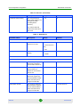
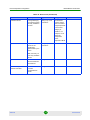
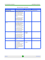
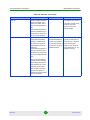
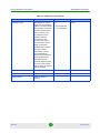
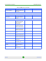
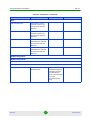
Document History
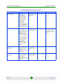
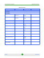
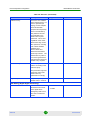
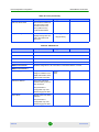
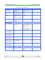
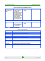
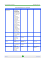
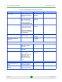
Document History
Changed Item
Description
Date
This is the document’s first publication.
January 2009
File Download
Revised
March 2009
New feature
March 2009
Revised
March 2009
Revised
May 2009
New feature
May 2009
Revised
June 2009
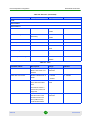
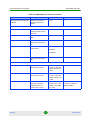
StarACS now runs on Oracle databases as well as MySQL
SW version 2.8
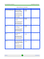
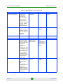
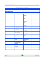
Section 6.4.6
Custom RPC
Section 6.4.8
Device Dependent
Parameters
Section 14
Device Dependent
Parameters
Section 14
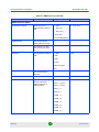
CSR
Section 12
Device Dependent
Parameters
Section 14
Oracle database
September 2009
User permission levels
Section 4.5
Updating a Group of CPEs
Section 7
Device Dependent
Parameters
When creating a new user, a permission level must be
defined
SW version 2.8
A filter capability has been added and it is now possible to
specify time periods for the update
SW version 2.8
Revised
SW version 2.8
September 2009
September 2009
September 2009
Section 14
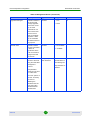
Updating a Group of CPEs
Section 7
Parameter tabs have been added to the Update Group
window :
SW version 2.8.5
November 2009
The Actions tab enables to manually configure commands
for a group of CPEs.
The Device ‘x’ tab displays the list of CPEs.
StarACS
ii
User Manual
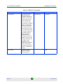
Document History
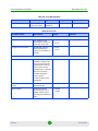
Changed Item
Description
Date
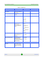
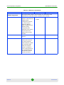
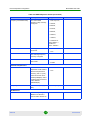
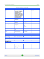
Licenses
A new menu option enabling to view the list of licenses and
to add a new license has been added.
SW version 2.8.5
Parameters for BreezeMAX Si 4000 CPEs have been added.
SW version 3.0.5
Section 4.10
Device Dependent
Parameters
December 2009
May 2010
Section 14.4
Configuring IIS to support
BreezeMAX Si 4000 CPE
Section 3
Monitoring
Section 8
Alert Settings
Before you can upload or download files to or from
BreezeMAX Si 4000 CPEs it is necessary to configure the
StarACS machine IIS server
SW version 3.0.5
An event monitoring tab has been added to enable monitoring
the state of the CPE and/or selected devices
SW version 3.0.5
An option has been added to send alerts as SNMP traps
SW version 3.0.5
Section 4.4
Device Info
May 2010
May 2010
May 2010
Control option buttons have been added to enable the
monitoring os the SOAP traffic between the CPE and
StarACS
SW version 3.0.5
A filter feature has been added to create filters based on
information from Inform or User’s information
SW version 3.0.5
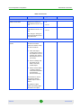
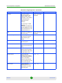
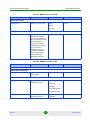
Parameters for NG_VG device have been added.
SW version 3.1.3
December 2010
Updated BreezeMAX Si 4000 CPE parameters.
SW version 3.1.3
December 2010
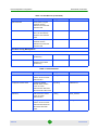
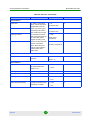
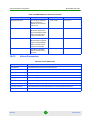
Added new feature for tracing CPEs
SW Version 3.1.6
January 2011
Device Info
Added ping option to test the CPE’s reachability
Section 6.4.1
Added Trace Route option to view the entire route (hops) to
the CPE
SW Version 3.1.6
January 2011
Provision Manager
New list menu displaying all the parameters that are sent to
the CPE for reprovisioning.
SW Version 3.1.6
January 2011
New menu for handling events.
SW Version 3.1.6
January 2011
Section 6.4.1
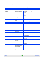
Creating a New CPE Profile
Section 5.3
Device Dependent
Parameters
May 2010
May 2010
Section 14.6
Device Dependent
Parameters
Section 14
Trace CPE
Section 6.2
Section 6.4.4
Events
Chapter 9
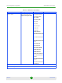
StarACS
iii
User Manual
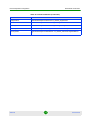
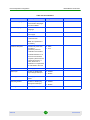
Document History
Changed Item
Description
Date
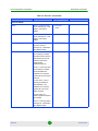
Whitelist
New list menu enabling to maintain a list of devices managed
by the StarACS Management Console
SW Version 3.1.6
January 2011
New list menu enabling to configure parameters relating to
the connection between the ACS and the CPE
SW Version 3.1.6
January 2011
Section 4.11
ACS Settings
Section 4.7
StarACS
iv
User Manual
Legal Rights
Legal Rights
© Copyright 2011 Alvarion Ltd. All rights reserved.
The material contained herein is proprietary, privileged, and confidential and
owned by Alvarion or its third party licensors. No disclosure thereof shall be made
to third parties without the express written permission of Alvarion Ltd.
Alvarion Ltd. reserves the right to alter the equipment specifications and
descriptions in this publication without prior notice. No part of this publication
shall be deemed to be part of any contract or warranty unless specifically
incorporated by reference into such contract or warranty.
Trade Names
Alvarion®, BreezeCOM®, WALKair®, WALKnet®, BreezeNET®, BreezeACCESS®,
BreezeLINK®, BreezeMAX®, BreezeLITE®, BreezePHONE®, 4Motion®, and/or other
products and/or services referenced here in are either registered trademarks,
trademarks or service marks of Alvarion Ltd.
All other names are or may be the trademarks of their respective owners.
“WiMAX Forum” is a registered trademark of the WiMAX Forum. “WiMAX,” the
WiMAX Forum logo, “WiMAX Forum Certified,” and the WiMAX Forum Certified
logo are trademarks of the WiMAX Forum.
Statement of Conditions
The information contained in this manual is subject to change without notice.
Alvarion Ltd. shall not be liable for errors contained herein or for incidental or
consequential damages in connection with the furnishing, performance, or use of
this manual or equipment supplied with it.
Warranties and Disclaimers
All Alvarion Ltd. (“Alvarion”) products purchased from Alvarion or through any of
Alvarion's authorized resellers are subject to the following warranty and product
liability terms and conditions.
Exclusive Warranty
(a) Alvarion warrants that the Product hardware it supplies and the tangible
media on which any software is installed, under normal use and conditions, will
be free from significant defects in materials and workmanship for a period of
fourteen (14) months from the date of shipment of a given Product to Purchaser
(the “Warranty Period”). Alvarion will, at its sole option and as Purchaser's sole
remedy, repair or replace any defective Product in accordance with Alvarion'
standard R&R procedure.
StarACS
v
User Manual
Legal Rights
(b) With respect to the Firmware, Alvarion warrants the correct functionality
according to the attached documentation, for a period of fourteen (14) month from
invoice date (the “Warranty Period”)”. During the Warranty Period, Alvarion may
release to its Customers firmware updates, which include additional performance
improvements and/or bug fixes, upon availability (the “Warranty”). Bug fixes,
temporary patches and/or workarounds may be supplied as Firmware updates.
Additional hardware, if required, to install or use Firmware updates must be
purchased by the Customer. Alvarion will be obligated to support solely the two (2)
most recent Software major releases.
ALVARION SHALL NOT BE LIABLE UNDER THIS WARRANTY IF ITS TESTING
AND EXAMINATION DISCLOSE THAT THE ALLEGED DEFECT IN THE PRODUCT
DOES NOT EXIST OR WAS CAUSED BY PURCHASER'S OR ANY THIRD
PERSON'S MISUSE, NEGLIGENCE, IMPROPER INSTALLATION OR IMPROPER
TESTING, UNAUTHORIZED ATTEMPTS TO REPAIR, OR ANY OTHER CAUSE
BEYOND THE RANGE OF THE INTENDED USE, OR BY ACCIDENT, FIRE,
LIGHTNING OR OTHER HAZARD.
Disclaimer
(a) The Software is sold on an “AS IS” basis. Alvarion, its affiliates or its licensors
MAKE NO WARRANTIES, WHATSOEVER, WHETHER EXPRESS OR IMPLIED,
WITH RESPECT TO THE SOFTWARE AND THE ACCOMPANYING
DOCUMENTATION. ALVARION SPECIFICALLY DISCLAIMS ALL IMPLIED
WARRANTIES OF MERCHANTABILITY AND FITNESS FOR A PARTICULAR
PURPOSE AND NON-INFRINGEMENT WITH RESPECT TO THE SOFTWARE.
UNITS OF PRODUCT (INCLUDING ALL THE SOFTWARE) DELIVERED TO
PURCHASER HEREUNDER ARE NOT FAULT-TOLERANT AND ARE NOT
DESIGNED, MANUFACTURED OR INTENDED FOR USE OR RESALE IN
APPLICATIONS WHERE THE FAILURE, MALFUNCTION OR INACCURACY OF
PRODUCTS CARRIES A RISK OF DEATH OR BODILY INJURY OR SEVERE
PHYSICAL OR ENVIRONMENTAL DAMAGE (“HIGH RISK ACTIVITIES”). HIGH
RISK ACTIVITIES MAY INCLUDE, BUT ARE NOT LIMITED TO, USE AS PART OF
ON-LINE CONTROL SYSTEMS IN HAZARDOUS ENVIRONMENTS REQUIRING
FAIL-SAFE PERFORMANCE, SUCH AS IN THE OPERATION OF NUCLEAR
FACILITIES, AIRCRAFT NAVIGATION OR COMMUNICATION SYSTEMS, AIR
TRAFFIC CONTROL, LIFE SUPPORT MACHINES, WEAPONS SYSTEMS OR
OTHER APPLICATIONS REPRESENTING A SIMILAR DEGREE OF POTENTIAL
HAZARD. ALVARION SPECIFICALLY DISCLAIMS ANY EXPRESS OR IMPLIED
WARRANTY OF FITNESS FOR HIGH RISK ACTIVITIES.
(b) PURCHASER'S SOLE REMEDY FOR BREACH OF THE EXPRESS
WARRANTIES ABOVE SHALL BE REPLACEMENT OR REFUND OF THE
PURCHASE PRICE AS SPECIFIED ABOVE, AT ALVARION'S OPTION. TO THE
StarACS
vi
User Manual
Legal Rights
FULLEST EXTENT ALLOWED BY LAW, THE WARRANTIES AND REMEDIES SET
FORTH IN THIS AGREEMENT ARE EXCLUSIVE AND IN LIEU OF ALL OTHER
WARRANTIES OR CONDITIONS, EXPRESS OR IMPLIED, EITHER IN FACT OR BY
OPERATION OF LAW, STATUTORY OR OTHERWISE, INCLUDING BUT NOT
LIMITED TO WARRANTIES, TERMS OR CONDITIONS OF MERCHANTABILITY,
FITNESS FOR A PARTICULAR PURPOSE, SATISFACTORY QUALITY,
CORRESPONDENCE WITH DESCRIPTION, NON-INFRINGEMENT, AND
ACCURACY OF INFORMATION GENERATED. ALL OF WHICH ARE EXPRESSLY
DISCLAIMED. ALVARION' WARRANTIES HEREIN RUN ONLY TO PURCHASER,
AND ARE NOT EXTENDED TO ANY THIRD PARTIES. ALVARION NEITHER
ASSUMES NOR AUTHORIZES ANY OTHER PERSON TO ASSUME FOR IT ANY
OTHER LIABILITY IN CONNECTION WITH THE SALE, INSTALLATION,
MAINTENANCE OR USE OF ITS PRODUCTS.
Limitation of Liability
(a) ALVARION SHALL NOT BE LIABLE TO THE PURCHASER OR TO ANY THIRD
PARTY, FOR ANY LOSS OF PROFITS, LOSS OF USE, INTERRUPTION OF
BUSINESS OR FOR ANY INDIRECT, SPECIAL, INCIDENTAL, PUNITIVE OR
CONSEQUENTIAL DAMAGES OF ANY KIND, WHETHER ARISING UNDER
BREACH OF CONTRACT, TORT (INCLUDING NEGLIGENCE), STRICT LIABILITY
OR OTHERWISE AND WHETHER BASED ON THIS AGREEMENT OR
OTHERWISE, EVEN IF ADVISED OF THE POSSIBILITY OF SUCH DAMAGES.
(b) TO THE EXTENT PERMITTED BY APPLICABLE LAW, IN NO EVENT SHALL
THE LIABILITY FOR DAMAGES HEREUNDER OF ALVARION OR ITS EMPLOYEES
OR AGENTS EXCEED THE PURCHASE PRICE PAID FOR THE PRODUCT BY
PURCHASER, NOR SHALL THE AGGREGATE LIABILITY FOR DAMAGES TO ALL
PARTIES REGARDING ANY PRODUCT EXCEED THE PURCHASE PRICE PAID
FOR THAT PRODUCT BY THAT PARTY (EXCEPT IN THE CASE OF A BREACH OF
A PARTY'S CONFIDENTIALITY OBLIGATIONS).
StarACS
vii
User Manual
Important Notice
Important Notice
This user manual is delivered subject to the following conditions and restrictions:
This manual contains proprietary information belonging to Alvarion Ltd. Such
information is supplied solely for the purpose of assisting properly authorized
users of the respective Alvarion products.
No part of its contents may be used for any other purpose, disclosed to any
person or firm or reproduced by any means, electronic and mechanical,
without the express prior written permission of Alvarion Ltd.
The text and graphics are for the purpose of illustration and reference only.
The specifications on which they are based are subject to change without
notice.
The software described in this document is furnished under a license. The
software may be used or copied only in accordance with the terms of that
license.
Information in this document is subject to change without notice. Corporate
and individual names and data used in examples herein are fictitious unless
otherwise noted.
Alvarion Ltd. reserves the right to alter the equipment specifications and
descriptions in this publication without prior notice. No part of this
publication shall be deemed to be part of any contract or warranty unless
specifically incorporated by reference into such contract or warranty.
The information contained herein is merely descriptive in nature, and does not
constitute an offer for the sale of the product described herein.
Any changes or modifications of equipment, including opening of the
equipment not expressly approved by Alvarion Ltd. will void equipment
warranty and any repair thereafter shall be charged for. It could also void the
user's authority to operate the equipment.
StarACS
viii
User Manual
Contents
Contents
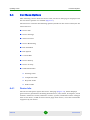
1. StarACS Overview ............................................................................... 1
2. Installation........................................................................................... 3
2.1
Prerequisites ..............................................................................................................3
2.1.1
2.2
Prerequisites for Oracle Installation..................................................................3
Installing StarACS......................................................................................................4
3. Getting Started .................................................................................. 12
3.1
Login .........................................................................................................................12
3.2
The Main Window.....................................................................................................13
4. Defining StarACS Settings ................................................................ 15
4.1
Defining ACS and DB Settings ...............................................................................15
4.2
Email Server Settings ..............................................................................................17
4.3
SNMP Server Settings .............................................................................................18
4.4
Alerts Settings..........................................................................................................20
4.5
User Management Settings .....................................................................................21
4.6
ACS (CPE) Users Settings.......................................................................................24
4.7
ACS Settings ............................................................................................................26
4.8
File Server Settings..................................................................................................27
4.9
Sessions ...................................................................................................................29
4.10 Licenses....................................................................................................................30
4.11 Whitelist ....................................................................................................................32
5. Defining a CPE Profile ....................................................................... 35
5.1
StarACS
Viewing and Managing CPE Profiles......................................................................35
ix
User Manual
Contents
5.1.1
Default Profile .................................................................................................39
5.2
Importing CPE Profiles ............................................................................................39
5.3
Creating a New CPE Profile.....................................................................................40
5.4
Fast Provisioning of a New CPE.............................................................................43
6. Updating a CPE.................................................................................. 44
6.1
Searching CPEs .......................................................................................................44
6.2
Viewing CPE List......................................................................................................46
6.3
Device Table Actions ...............................................................................................50
6.4
List Menu Options....................................................................................................52
6.4.1
Device Info......................................................................................................52
6.4.2
Device Settings...............................................................................................54
6.4.3
Advanced View ...............................................................................................56
6.4.4
Provision Manager..........................................................................................58
6.4.5
Device Monitoring ...........................................................................................59
6.4.6
File Download .................................................................................................61
6.4.7
File Upload......................................................................................................65
6.4.8
Custom RPC...................................................................................................68
6.4.9
Device History.................................................................................................69
6.4.10 Device Activity ................................................................................................70
6.4.11 Pending, Completed, Rejected, and Failed Tasks..........................................71
7. Updating a Group of CPEs ................................................................. 74
7.1
Viewing CPE Groups ...............................................................................................74
7.2
Importing a File for Updating a Group ...................................................................79
7.3
Creating a New CPE Group .....................................................................................80
7.4
Defining a Filter Group ............................................................................................83
StarACS
x
User Manual
Contents
8. Monitoring.......................................................................................... 87
8.1
Viewing Events.........................................................................................................87
8.2
Importing an Event Monitoring File........................................................................92
8.3
Creating a New Event ..............................................................................................94
8.4
Viewing an Event Log ..............................................................................................96
9. Events ................................................................................................ 98
9.1
Viewing Events.........................................................................................................98
9.2
Importing an Event File .........................................................................................102
9.3
Creating a New Event ............................................................................................104
10. Reports .......................................................................................... 107
10.1 CPE Distribution Report ........................................................................................108
10.2 CPE Registration Report .......................................................................................110
10.3 Pending Tasks Report ...........................................................................................111
10.4 Rejected Tasks Report ..........................................................................................113
10.5 Activity ....................................................................................................................113
10.5.1 Profiles Activity Report..................................................................................114
10.5.2 Update a CPE Activity Report.......................................................................116
10.5.3 Update Group Activity Report .......................................................................117
10.5.4 System Activity Report..................................................................................119
10.6 Updates Report ......................................................................................................120
11. File Management ........................................................................... 123
11.1 File Management ....................................................................................................123
11.2 Adding a File to the File Server ............................................................................124
12. CSR ................................................................................................ 127
12.1 Configuration.........................................................................................................127
12.2 User Management ..................................................................................................129
12.2.1 Admin Access Level .....................................................................................130
StarACS
xi
User Manual
Contents
12.2.2 Csr Access Level ..........................................................................................131
12.2.3 User Access Level ........................................................................................131
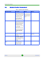
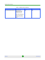
13. Default Profile Parameters............................................................ 132
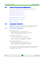
14. Device Dependent Configuration .................................................. 134
14.1 BreezeMAX 1000 CPEs ..........................................................................................134
14.1.1 File Transfer Configurations .........................................................................134
14.1.2 List of Parameters.........................................................................................135
14.1.3 Inform Parameters ........................................................................................158
14.2 BreezeMAX 2000 CPEs ..........................................................................................160
14.2.1 File Transfer Configurations .........................................................................160
14.2.2 List of Parameters.........................................................................................161
14.2.3 Inform Parameters ........................................................................................176
14.3 BreezeMAX 3000 CPEs ..........................................................................................177
14.3.1 File Transfer Configurations .........................................................................177
14.3.2 List of Parameters.........................................................................................178
14.3.3 Inform Parameters ........................................................................................195
14.4 BreezeMAX Si 4000 CPEs......................................................................................196
14.4.1 File Transfer Configurations .........................................................................196
14.4.2 List of Parameters.........................................................................................197
14.4.3 Inform Parameters ........................................................................................252
14.5 BreezeMAX 5000 CPE ............................................................................................253
14.5.1 File Transfer Configurations .........................................................................253
14.5.2 List of Parameters.........................................................................................254
14.5.3 Inform Parameters ........................................................................................276
14.6 NG_VG.....................................................................................................................277
14.6.1 File Transfer Configurations .........................................................................277
StarACS
xii
User Manual
Contents
14.6.2 List of Parameters.........................................................................................277
14.6.3 Inform Parameters ........................................................................................301
Glossary ............................................................................................... 302
StarACS
xiii
User Manual
StarACS Overview
1.
StarACS Overview
This document describes using the StarACS Admin CPE Remote Management
application. This product enables the administrator to manage, monitor, and
diagnose customer premises equipment (CPE) complying with the TR-069
protocol.
Alvarion’s StarACS is a carrier-class ACS (Auto Configuration Server)
management system designed for managing WiMAX CPEs (Customer Premises
Equipment) over TR-069 protocol.
Built on an industry proven Application Server architecture, the StarACS is
scalable, allowing it to support a virtually unlimited number of CPE devices.
Alvarion’s StarACS standards-based solution is designed to centralize and
simplify the management, provisioning, monitoring, and delivery of broadband
services to CPE.
StarACS Value Proposition:
Reduces cost of provisioning new subscribers.
Reduces cost of provisioning new services to subscribers.
Reduces on-going maintenance support cost.
The StarACS provides comprehensive management support for the entire CPE
service life cycle, including Zero-Touch installation, provisioning, software
upgrades, configuration backups, and on line support for customer support
representatives.
Main features:
Zero-touch provisioning
Activating/Deactivating a service
Diagnosing and configuring CPEs
Managing and updating the firmware
Uploading files from the CPE
Verifying the CPE's connectivity status
StarACS
1
User Manual
StarACS Overview
Resetting/Rebooting the CPE
Displaying the CPE's activity log
Monitoring CPEs
The StarACS Management application is accessed through a web browser. The
web interface consists of the following sections:
Default Profile - a default generic provisioning profile for all
unknown/unmanaged CPEs
CPE Profile - a default provisioning profile for a specific CPE model
Update a CPE - to manage a specific CPE
Update Group - to manage groups of CPEs
Monitoring - to monitor events that show the state of the CPE and/or selected
parameters
Reports - to track and monitor CPE and system activity
File Management - to manage firmware image and vendor configuration files
Settings - for initial setup of the system
StarACS
2
User Manual
Installation
Prerequisites
2.
Installation
2.1
Prerequisites
Before installing the StarACS, verify that the following software is installed:
Newly installed, dedicated Windows 2008 Server
Remote or Local (ACS Server) Database.
The following databases are supported:
»
MySQL V5.1 (latest release)
»
Oracle 10g
NOTE
When installing StarACS with the Oracle server on a separate machine, the Oracle client must be
installed on the StarACS machine. The Oracle client version must be the same as the Oracle server
version.
IIS 5.0 or above
.NET Framework 2.0
FTP and TFTP servers - can be either a single server supplying both (e.g.
3cDaemon-http://support.3com.com/software/utilities_for_windows_32_bit.
htm) or separate FTP server (e.g. FileZilla - http://filezilla-project.org) and
TFTP server (e.g. pumpkin - http://kin.klever.net/pumpkin/binaries)
HTTP File Server - is configured using the operating system IIS
H/W capacity and requirements according to the release notes
2.1.1
Prerequisites for Oracle Installation
Before StarACS can be activated with an Oracle database, it is necessary to
manually create the database and run the schema/users scripts.
To create Oracle database, users and import schema:
1
StarACS
Manually create an empty database on the Oracle server.
3
User Manual
Installation
Installing StarACS
2
Copy the Oracle scripts (the createFriendlyDB.sql file and the acs, admin, csr,
and dps folders) from the Setup folder in the StarACS kit to the Oracle server.
3
Open a command prompt and locate the folder where the scripts were copied.
»
In the command prompt located in the script folder, run the command:
sqlplus system/password@dbname where "password" and "dbname"
must be filled with the proper information. The SQL prompt is displayed.
»
At the SQL prompt, run the command @createFriendlyDB.sql. Accept
the default options for the prompted tablespace location or change to a
specific place on the disk. The user and schema creation begins, at the end
of which a successful message is displayed.
2.2
Installing StarACS
It is recommended that you close any running applications on the computer. The
installation should be run by a user with administrator privileges.
To install StarACS:
1
Double-click the setup.exe file on the installation CD. The system
automatically detects whether the following applications are installed:
StarACS
»
JDK 1.5 – Java Development Kit
»
MySQL Connector – required for connection to a MySQL database
4
User Manual
Installation
Installing StarACS
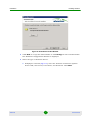
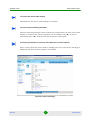
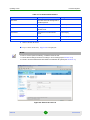
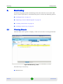
If the applications are not installed Figure 1 is displayed.
Figure 1: Additional Application Required
2
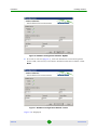
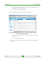
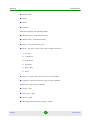
Click Install to begin installing the required applications. Figure 2 is
displayed.
Figure 2: Installing additional applications
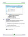
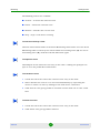
Click Yes if installing on a MySQL database or click No if installing on Oracle.
Figure 3 is displayed.
StarACS
5
User Manual
Installation
Installing StarACS
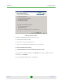
Figure 3: Installation Wizard
3
Click Next. The License Agreement Window is displayed.
Figure 4: License Agreement Window
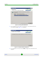
4
Accept the terms of the License Agreement and click Next. The Destination
Folder Window is displayed.
StarACS
6
User Manual
Installation
Installing StarACS
Figure 5: Destination Folder Window
5
Click Next to accept the default folder or click Change to select another folder.
The Database Configuration Window is displayed.
6
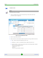
Select the type of Database Server:
a
If MySQL is selected (Figure 6), enter the Database Connection options:
Server URL, Server Port, User Name, and Password. Click Next.
StarACS
7
User Manual
Installation
Installing StarACS
Figure 6: Database Configuration Window- MySQL
b
If Oracle is selected (Figure 7), enter the Database Connection options:
Server URL, Server Port, User Name, Password and Service Name. Click
Next.
Figure 7: Database Configuration Window- Oracle
Figure 8 is displayed.
StarACS
8
User Manual
Installation
Installing StarACS
Figure 8: Ready to Install
7
Verify the following information on the screen:
»
Destination Folder location
»
Database Connection parameters
»
JDK 1.5 is installed and pointing to the correct path
»
IIS is installed and running
»
.NET Framework 2.0 is installed and registered to IIS
To proceed with the installation, click Install. To change settings or make
corrections, click Back.
The Installing StarACS Window is displayed.
StarACS
9
User Manual
Installation
Installing StarACS
Figure 9: Installing StarACS Window
8
The installation process takes several minutes. Once StarACS has been
successfully installed Figure 10 is displayed.
Figure 10: Installation Wizard Completed
9
For installations on Oracle servers ONLY, configure the connection to the
database:
StarACS
10
User Manual
Installation
Installing StarACS
a
In the folder C:\Program Files\Alvarion\StarACS\ACS\server\dps\deploy
open the file oracle-ds.xml. Change the IP address to the actual IP address
(not 127.0.0.1 or loop-back), the Port and the SID to the correct values for
the Oracle server. These parameters appear in three different places in the
file, enclosed by the <connection-url> tags.
b
In the folder C:\Inetpub\wwwroot\StarACS\XML open the file
ConnectionStrings.xml. Change the database type to
Oracle(<DBType>Oracle</DBType>) and change the values for the IP, Port
and SID inside the tags <Oracle>).
c
Copy the ojdbc14.jar file from the Oracle installation to the C:\Program
Files\Alvarion StarACS\ACS\server\dps\lib folder, overwriting the
existing file. (For example: The ojdbc14.jar file can be found in the folder
D:\Oracle\product\10.1.0\Client_1\jdbc\lib).
10 Click Finish to exit the installation wizard.
StarACS is installed as an automatic Windows service and can be managed from
Service Manager.
IMPORTANT
When uninstalling the application the service must be first stopped.
When uninstalling, some operations may need to be completed manually:
StarACS
»
Remove the Alvarion directory under program files
»
Remove all the staracs entries from the windows registry
11
User Manual
Getting Started
Login
3.
Getting Started
3.1
Login
To log in to the StarACS application for the first time, the user must have
administrator permission. The default user name is admin, and the default
password is admin. This default cannot be changed during the installation.
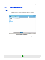
To start StarACS:
1
In the web browser, enter the link to the StarACS home page (http://<ACS ip
address>/StarACS/Default.aspx) and press Enter. The login window is
displayed.
Figure 11: Login Window
2
Enter the administrator user name and password (default name and
password: admin/admin) and press Enter or click Login. The StarACS Update
a CPE page is displayed.
StarACS
12
User Manual
Getting Started
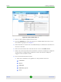
The Main Window
Figure 12: StarACS Main Window
3.2
The Main Window
The StarACS user interface consists of four main areas:
Main tabs: Select the preferred administration functionality
Menu per tab: An options menu per each tab
Main screen area: The main data area
Buttons per screen: Action buttons per each screen
StarACS
13
User Manual
Getting Started
The Main Window
Figure 13: Main Window
StarACS
14
User Manual
Defining StarACS Settings
4.
Defining ACS and DB Settings
Defining StarACS Settings
Before you can use the StarACS for managing CPEs, you need to define initial
settings, such as server details, allowed users, etc.
The following sections describe the Settings tab and its menu options:
“Defining ACS and DB Settings” on page 15
“Email Server Settings” on page 17
“SNMP Server Settings” on page 18
“Alerts Settings” on page 20
“User Management Settings” on page 21
“ACS (CPE) Users Settings” on page 24
“ACS Settings” on page 26
“File Server Settings” on page 27
“Sessions” on page 29
“Licenses” on page 30
“Whitelist” on page 32
4.1
Defining ACS and DB Settings
The ACS and DB menu option enables setting system parameters for the ACS and
database servers. These settings should only be changed if ACS is installed in
distributed architecture.
To define ACS and DB settings:
1
StarACS
Click the ACS and DB menu option.
15
User Manual
Defining StarACS Settings
Defining ACS and DB Settings
Figure 14: ACS and DB Window
2
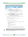
Modify the following parameters as required:
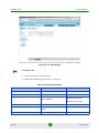
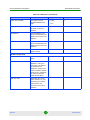
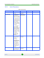
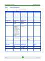
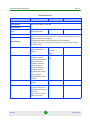
Table 1: ACS and DB Settings
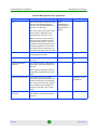
Parameter
Description
ACS address:
IP address
ACS IP address
Port
ACS port number.
Note: In order to be able to change the port, it is necessary to also
change the port on the ACS server. Contact Alvarion Customer Support
for configuration details.
Database type:
Database type
The database type. The possible values are MySQL or Oracle.
ACS database settings:
IP address
ACS database server's IP address
Database name
ACS database name
Username
ACS database username
Password
ACS database password
Login database settings:
IP address
StarACS
Login database server IP address
16
User Manual
Defining StarACS Settings
Email Server Settings
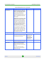
Table 1: ACS and DB Settings
Parameter
Description
Database name
Login database name
Username
Login database username
Password
Login database password
Database ACS users:
IP address
ACS users database server's IP address
Database name
ACS users database name
Username
ACS users database username
Password
ACS users database password
3
4.2
Click Save to save your settings.
Email Server Settings
You can define an SMTP Server address for sending alerts to inform the operator
about system events (e.g., database or server down).
To define Email server settings:
1
Click the Email Server menu option to enable setting system parameters for
the email server.
StarACS
17
User Manual
Defining StarACS Settings
SNMP Server Settings
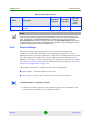
Figure 15: E-mail Server Window
2
Set the following fields as required:
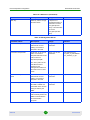
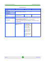
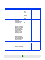
Table 2: E-mail Server Settings
3
4.3
Parameter
Description
Host
email server host name
Port
email server port number
Enable SSL
check box to enable or disable SSL
Login
email server username
Password
email server password
From
email address used to send alerts
Subject
text used as the subject line in email alerts
Click Save to save your settings.
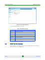
SNMP Server Settings
Alerts configured to be triggered by loss of connectivity of the ACS or database
servers can be sent as an SNMP trap.
StarACS
18
User Manual
Defining StarACS Settings
SNMP Server Settings
To enable sending alerts as SNMP trap:
In the Alerts window (Figure 17), check the Enable SNMP alerts box.
To configure the SNMP server:
1
Click the SNMP Server menu option.
Figure 16: SNMP Server Window
2
3
StarACS
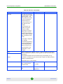
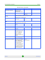
Modify the following fields as required:
Field
Description
SNMP Manager IP
The IP address of the SNMP server to
which the trap is sent
Port
The SNMP Server port
SNMP Community
The name of SNMP Community
Version
The SNMP version
Comment
The comment displayed
Click Save to save your settings.
19
User Manual
Defining StarACS Settings
4.4
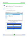
Alerts Settings
Alerts Settings
Alerts can be configured to be triggered by loss of connectivity of the ACS or
database servers.
To define Alerts settings:
1
Click the Alerts menu option to enable configuring alerts.
Figure 17: Alerts Window
2
Select the notification method. The possible options are: via this program,
Enable SNMP alerts, via email, or via sms. You can select more than one
option, or all.
»
If you select via e-mail or via sms, choose whether to send once, or to send
periodically. To send periodically, enter the periodic interval in seconds.
»
If you select via e-mail, click the Add button and enter the e-mail address
to receive the alert message. The e-mails will be sent via the SMTP Server
that was configured previously (see Section 4.2).
»
If you select via sms, click the Add button and enter the telephone number
to receive the alert message. This feature requires an external SMS service.
StarACS
20
User Manual
Defining StarACS Settings
3
User Management Settings
Enter a valid email address or phone number and click Save to add users to
the list. Alert notification will be sent to all email addresses and phone
numbers in the list.
NOTE
If you select an email address or telephone number from the lists that appear on the screen, the
Delete button is activated. Click Delete to remove the selected item from the list.
4.5
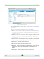
User Management Settings
This page allows managing the users of the StarACS application.
Click the User Management menu option to display a table of users.
Figure 18: User Management Window
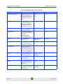
The table displays the following fields:
Username
Full name
E-mail address
Permission
StarACS
21
User Manual
Defining StarACS Settings
User Management Settings
The following controls are available:
Add - creates a new user
Delete - removes a user
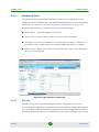
To create a new user:
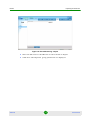
1
Click Add. The following page is displayed:
Figure 19: Adding New User
StarACS
2
Enter the Username and Password for the new user.
3
Enter the user's Name and Email address.
22
User Manual
Defining StarACS Settings
4
User Management Settings
Check a permission level for the user.
»
Limited - users have Read Only rights on one CPE and cannot perform
operations on more CPEs at the same time. The CPE Profile, Update Group,
Reports, File Management and Settings menus are not available.
»
User - users have Read/Write access on one CPE and cannot perform
operations on more CPEs at the same time. The CPE Profile, Update Group,
Reports, File Management and Settings menus are not available.
»
5
Admin - users have full rights.
Click Save. The new user is added to the user table.
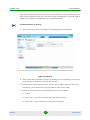
To edit a user:
1
Click on the table row of the user entry to be edited. The following page is
displayed:
Figure 20: Editing User
StarACS
2
Modify the desired fields.
3
Click Save. The user entry is modified in the user table.
23
User Manual
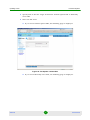
Defining StarACS Settings
ACS (CPE) Users Settings
To delete a user:
4.6
1
Check the box in the table row of the user entry to be edited.
2
Click Delete. A confirmation window appears.
3
Click OK. The user is deleted.
ACS (CPE) Users Settings
ACS Users is a white list of entries used to identify CPEs connected to ACS. Each
CPE is assigned a “user” name and password that the management system
identifies and matches to the database. Only upon identification the
communication with the specific CPE is allowed. It is only necessary to define ACS
Users if an authentication method is required between the CPE and ACS. If not,
the default users that come with the installation are enough to support
communication, but they must not be deleted.
Click the ACS Users menu option to enable adding or deleting ACS users.
Figure 21: ACS Users
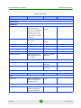
The following fields are displayed in the ACS user table:
Login - ACS user name
StarACS
24
User Manual
Defining StarACS Settings
ACS (CPE) Users Settings
Password - ACS user password
Valid from - ACS user start effective date and time
Valid until - ACS user end effective date and time
To create a new ACS user:
1
Click Add. The following page is displayed:
Figure 22: New ACS User
2
Enter the Login and Password for the new user.
3
Enter the user's Name and Email.
4
Click Send Update. The new ACS user is added to the ACS user table.
To edit an ACS user:
StarACS
1
Click on the table row of the user entry to be edited.
2
Modify the desired fields.
3
Click Send Update. The user entry is modified in the user table.
25
User Manual
Defining StarACS Settings
ACS Settings
To delete an ACS user:
4.7
1
Check the box in the table row of the ACS user entry to be edited.
2
Click Delete. A confirmation window appears.
3
Click OK. The ACS user is deleted.
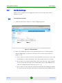
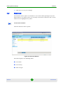
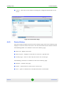
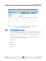
ACS Settings
The ACS Settings window enables to configure parameters relating to the
connection between the ACS and the CPE.
To define ACS settings:
1
Click the ACS Settings menu option to enable ACS settings configuration.
Figure 23: ACS Settings
2
StarACS
Modify the following fields as required:
26
User Manual
Defining StarACS Settings
File Server Settings
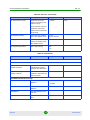
Field
Description
Enable whitelist
Check to enable whitelist or uncheck to disable. When
enabled, only the devices listed in the whitelist will be
able to register to the ACS. See Section 4.11.
Retrieve data tree
Select one of the following discovery mode options:
one by one
by root object only (bulk)
3
4.8
HTTP session timeout
The timeout (in seconds) of the HTTP session between
the ACS and the CPE.
Store device history log in
days
Sets the number of days during which the devices’
history log is stored.
Enable event monitoring
Check to enable transmission of Events.
Web service URL for event
monitoring
The URL of the web service for events redirection.
Disable digest authentication
URL
Check to disable digest authentication.
Disable basic authentication
URL
Check to disable basic authentication.
Disable no authentication
URL
Check to disable no authentication.
Click Save.
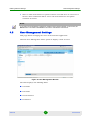
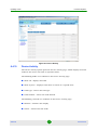
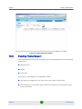
File Server Settings
You can define the file server, CPE download server, and CPE upload file server.
These settings are device dependent. For more information for a specific device
refer to Section 14.
To define server settings
1
StarACS
Click the File Server menu option to enable server configuration.
27
User Manual
Defining StarACS Settings
File Server Settings
Figure 24: File Server Window
2
Set the address, username and password of the following:
»
File management ftp server - URL address of the file server used for
download (FTP).
Example:
ftp://<ftp server machine IP>
user: ftp ACS user
password: ftp ACS user password
»
Download server - URL address from where the CPE downloads files when
using the default from list file download option.
Note: The settings must be changed according to the main CPE type in
use.
»
File management upload ftp server - URL address of the file server used for
upload (FTP)
Example:
ftp://<ftp server machine IP>
user: ftp ACS user
password: ftp ACS user password
»
CPE upload server - URL address to where the CPE uploads files when
using the default from list file upload option.
Note: The settings must be changed according to the main CPE type in
use.
StarACS
28
User Manual
Defining StarACS Settings
3
4.9
Sessions
Click Save to save your settings.
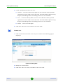
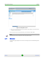
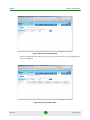
Sessions
The Sessions menu option is available to users with admin privileges only and
allows them to see which users are currently connected to StarACS. The current
admin user is highlighted in yellow.
To view user sessions:
Click the Sessions menu option.
Figure 25: Sessions Window
The table displays the following fields:
User Name
Last Activity
Time of Login
StarACS
29
User Manual
Defining StarACS Settings
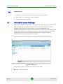
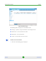
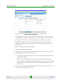
4.10
Licenses
Licenses
The Licenses menu option enables viewing the list of licenses and adding new
licenses.
To view licenses:
Click the Licenses menu option.
Figure 26: Licenses Window
The table displays the following fields:
Created - the date when the license was loaded
Customer Name - the name of the customer for whom the license was created
Time Expiration - the number of days allowed for evaluation purposes or the
expiry date of the license. If the license has no expiry date, the value is
Unlimited. A warning message will be displayed two weeks before the
expiration date.
StarACS
30
User Manual
Defining StarACS Settings
Licenses
Managed CPE - the maximum number of managed CPEs. Managed CPEs are
CPEs that are currently registered in ACS.
Registered CPE - the maximum number of registered CPEs. Registered CPEs
are all the CPEs that have ever been registered in the system, including CPEs
that have been deleted.
CPEAdmin Users - the maximum number of concurrent user sessions allowed.
When the number of CPEAdmin Users is reached, 3 more sessions can login to
ACS from different machines. You can see which users are connected in
Settings -> Sessions.
CSR Users - the maximum number of concurrent users allowed to connect
through the CSR application
The last row of the table displays the sum of the components of all the licences
that have been loaded and is color-coded as follows:
License is active - blue
License limit has been reached - red
If one of the fields of the last license added has an Unlimited value, then the
overall value for that field is Unlimited. If one of the other licenses has an
Unlimited value for a particular field, but the last license added has a value for
that field, the overall value for the field is the sum of the numbers, and does not
take the Unlimited value into account.
If the number of active sessions of one of the applications is exceeded, an error
message is displayed on the login screen and the next user cannot login. A user
with admin privileges can login and free some sessions (see Section 4.9) so that
users can login to the system.
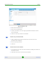
To add a new license:
1
StarACS
Click Add. The following page is displayed:
31
User Manual
Defining StarACS Settings
Whitelist
Figure 27: Adding New License
2
Enter the key information for the new license and click Save. The new license
is added to the license list.
Once the ACS receives a new license key, the new license takes effect.
NOTE
The same license cannot be loaded twice onto the same StarACS system.
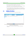
4.11
Whitelist
The Whitelist page displays a list of devices managed by the StarACS Management
Console.
StarACS
32
User Manual
Defining StarACS Settings
Whitelist
Figure 28: Whitelist Page
The following fields are displayed in the Whitelist table:
IP Range - specifies a range of IP addresses for managed devices
Manufacturer - device manufacturer name
Model Name - device model name
Created - date and time entry was created
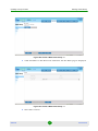
To add a device to the whitelist:
1
StarACS
Click Add. The following page is displayed.
33
User Manual
Defining StarACS Settings
Whitelist
Figure 29: Whitelist - Add
2
Select the device Manufacturer.
3
Select the device Model Name.
4
To filter by IP address, enter the range of permissible IP addresses for the
device in IP Range.
5
Click Save. The entry is added to the whitelist.
To edit an entry in the whitelist table:
1
Click any field in the row of the selected entry in the table. The event
parameter table is displayed.
2
Edit the required parameters.
3
Click Save.
To delete a device from the whitelist:
1
In the Whitelist table, select the rows for deletion by clicking the checkbox on
the leftmost column.
2
StarACS
Click Delete. The entry is removed from the whitelist.
34
User Manual
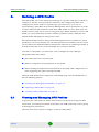
Defining a CPE Profile
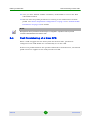
5.
Viewing and Managing CPE Profiles
Defining a CPE Profile
The CPE profile serves for default provisioning of a specific CPE type. It allows to
configure a specific set of parameters, firmware and configuration files to be
configured on all the CPEs of a specific type upon discovery or in case of
reprovisioning. All profiles must include Management Server parameters in order
to allow communication with the CPE. Each CPE model can have more than one
profile, however only one is active at any given time. When deleting an active CPE
Profile, you must manually reactivate another profile if it exists, otherwise the
Default Profile will apply for this product class.
The Default Profile contains only generic Management Server parameters. These
parameters can not be deleted, nor can other parameters be added, but the values
can be edited. The Default Profile is intended for unknown or unmanaged CPEs. It
is built in when the server is first installed and cannot be deleted.
To define a CPE profile, you must first creat a template for this CPE type.
The profile takes effect when:
The CPE connects for the first time
When a change has been performed on the profile
When clicking the Reprovision CPE button in the single CPE configuration or
when triggering this option through the NBI.
Click the CPE Profile tab to display the CPE Profile page. The CPE Profile menu
has the following options:
“Viewing and Managing CPE Profiles” on page 35
“Importing CPE Profiles” on page 39
“Creating a New CPE Profile” on page 40
5.1
Viewing and Managing CPE Profiles
In general, the CPE sends its whole data model to the StarACS during the first
connection; on subsequent Inform connections, the CPE sends only a select group
of management parameters.
Click the View menu option to display a table of CPE profiles:
StarACS
35
User Manual
Defining a CPE Profile
Viewing and Managing CPE Profiles
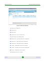
Figure 30: CPE Profiles Window
The table may be filtered by:
Manufacturer
Model name
Profile status - (Active or Not Active)
The table displays the following fields:
Manufacturer - CPE manufacturer or DEFAULT
Model name - CPE model name or DEFAULT
Profile name - CPE profile name or DEFAULT
Created - CPE profile creation date and time
Creator - username who created the CPE profile
Version - CPE profile version number
The following actions are available:
StarACS
36
User Manual
Defining a CPE Profile
Viewing and Managing CPE Profiles
Sort - sorts the table by the selected field
Edit - edits the selected profile
Export - exports the selected profile to an xml formatted file
Activate - activates the selected profile. An unknown/unmanaged CPE will
receive the active default profile parameters when first connecting to the ACS.
Deactivate - deactivates the selected profile
Delete - deletes the selected profile
To sort the profile table by a field:
Click the selected field name in the profile table header row. The profile table is
sorted by the selected field in ascending order (▲). To sort in descending order
(▼), click the selected field name again.
To export a profile:
Click Export for the selected profile entry in the table. A dialog box opens asking if
you want to open or save the profile file.
To activate a profile:
1
Check the box in the row for the selected profile entry in the table or use the
check all functionality in each page.
2
Click Activate. The profile is activated and the table row is color-coded blue.
To edit a profile:
1
Click any field in the row of the selected entry in the table. The profile
parameter table is displayed.
StarACS
37
User Manual
Defining a CPE Profile
Viewing and Managing CPE Profiles
Figure 32: Editing CPE Profile
2
Select whether or not to send a request for the full data tree from existing
CPEs. This will configure whether upon reprovisioning the CPE, the full data
tree will be retrived or not. It does not apply to the CPE discovery phase.
3
Select a condition from the drop-down list or create a new condition.
4
Click the parameter group tab (e.g. Management Server).
5
Edit the parameter values (Refer to “Device Dependent Configuration” on
page 134).
6
To view the entire parameter tree, click Advanced View.
7
To save the profile without activating it, click Save. To save the profile and
activate it, click Save and Activate. The profile is saved. If activated, the table
row is color-coded blue. Activating automatically deactivates any previous
active profile for a specific CPE model (if exists).
8
StarACS
You can deactivate the profile by using the buttons located at the bottom.
38
User Manual
Defining a CPE Profile
5.1.1
Importing CPE Profiles
Default Profile
The default profile is intended for CPEs for which there is no dedicated profile,
and contains a few basic management parameters to facilitate the connection
between the ACS and CPE. Unknown CPEs can be fully managed except for
having a common CPE configuration file. There can be several Default profiles;
however, only one can be active at any given time. The active default profile
parameters are assigned to a newly connected CPE. See “Default Profile
Parameters” on page 132.
Figure 34: Default Profile Window
5.2
Importing CPE Profiles
Importing a profile is useful for rapidly performing backup-restore or
pre-configuring CPE profiles instead of creating them manually. You can import
existing xml profile files to your list of profiles and can activate a profile as the
currently used default profile for new CPEs.
To import a CPE profile:
1
Click the Import menu option to import a profile. The following page is
displayed:
StarACS
39
User Manual
Defining a CPE Profile
Creating a New CPE Profile
Figure 35: Import Profile Window
5.3
2
Enter the file name or click Browse to select the file to import.
3
Click Open. The imported profile is displayed.
Creating a New CPE Profile
Creating a CPE profile means that all CPEs of the same manufacturer and model
that comply with the selected condition will receive this profile as part of the initial
connection. A CPE profile is translated into a device configuration profile with TR
objects and parameters. You can also create a new default profile to be used as
your default for unknown/unmanaged CPEs.
A new CPE profile can be created only if a profile template exists.
To create a new CPE profile:
1
Make sure a template exists for the CPE you want to create a new profile. If
not, create a template as follows:
StarACS
40
User Manual
Defining a CPE Profile
a
Creating a New CPE Profile
Click Update a CPE and select a CPE with the Manufactuer and Model
Name for which you want to create the template. The CPE for which the
profile is created must have a pre-created template.
b
Click the Device Info menu option; the information about the device is
displayed.
2
c
Click the Create Template button; a template is created.
d
Click CPE Profile to return to the CPE Profile page.
Click the New menu option. The following page is displayed:
Figure 36: Create a New CPE Profile
3
Select the Manufacturer and Model name. If a template exists for this model, a
page similar to the following is displayed:
StarACS
41
User Manual
Defining a CPE Profile
Creating a New CPE Profile
Figure 37: New CPE Profile
4
Select whether or not to send a request for the full data tree from existing
CPEs. This will configure whether upon reprovisioning the CPE, the full data
tree will be retrived or not. It doesnot apply to the CPE discovery phase.
5
Click New Condition to add conditions and click Next. If no condition is
\
defined, the profile will apply to all CPEs of the selected Manufacturer and
Model Name.
6
Enter a Condition Name and click Next.
7
Click Add to define the condition.
8
Check the box to select the type of filter condition. The filter can be based on
information from Inform or on User’s Info.
»
User’s Info is information about the customer behind the CPE and can only
be added from NBI.
»
Inform allows configuring conditions based on the information in the
inform sent by a specific CPE. This profile will apply only to CPEs sending
the inform with that specific parameter. For Inform parameters refer to
Section 14.
9
Select the name of the condition from a list, enter a value and click Save. The
condition will be displayed in a table.
StarACS
42
User Manual
Defining a CPE Profile
Fast Provisioning of a New CPE
10 Once you have defined all filter conditions, click Finish to reurn to the New
CPE Profile window.
11 Edit the relevant profile parameters according to the CPE model or default
profile. See “Device Dependent Configuration” on page 134 or “Default Profile
Parameters” on page 132 for details.
NOTE
Management Server parameters must always be configured in a profile in order to provide
connection data between ACS and the CPE.
5.4
Fast Provisioning of a New CPE
When a CPE is logged into the ACS system for the first time, parameters
configured in the CPE Profile are automatically set on the CPE.
If there is no profile model for the specific CPE model or manufacturer, the default
profile values are applied to the newly introduced CPE.
StarACS
43
User Manual
Updating a CPE
6.
Searching CPEs
Updating a CPE
An update to a specific CPE can originate from the following sources:
Update of an individual CPE under the "Update a CPE" tab
Update individual CPEs as part of a group update under the "Update group"
tab
CPE settings sent from external systems via northbound interface (API)
A combination of the above
Note that the update tasks are executed according to a queue utilizing FIFO.
The CPE Profile mechanism has its own queue. When a firmware update is sent to
the CPE, all other updates will be put on hold until the firmware is updated.
Click the Update a CPE tab to display the following menu options:
Search
List
The Search menu option enables listing specific CPE devices. The List menu
option lists all CPE devices in the system (see “List Menu Options” on page 52).
6.1
Searching CPEs
Click the Search menu option to enable searching for a device by one of the
following parameters:
Serial Number
MAC address
Authentication Username
Running SW Version
Shadow SW Version
Serving BS ID
StarACS
44
User Manual
Updating a CPE
Searching CPEs
Con Req URL (can be used for searches based on WAN IP addressfor CPEs that
do not support external IP addresses if the Search match only option is not
checked)
External IP Address
Figure 38: Search Window
To search for CPE devices:
1
Select the parameter type to be searched for from the Search by list.
2
Enter a partial or complete parameter string in the lower text box.
3
To list complete parameter string matches only, check the Search exactly box.
4
Click Search. A table with the list of matching CPE devices is displayed. The
view of the table can be changed (see Section 6.2)
In the example below, all CPE devices were searched for serial number containing
the string '2_5'.
StarACS
45
User Manual
Updating a CPE
Viewing CPE List
NOTE
When searching by mac address, the expression can use any of the following as delimiters:
hyphen, colon, space.
Figure 39: Search Example
6.2
Viewing CPE List
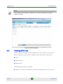
Click the List menu option to list all CPE devices in the system. A table of all
devices registered in the system is displayed. The table may be filtered by:
View
Manufacturer
Model name
The following controls are available:
Edit view - enables to modify the parameters displayed in the current view
StarACS
46
User Manual
Updating a CPE
Viewing CPE List
New view - enables to select the parameters to be displayed in a new view
Delete - deletes the selected CPE from the list
Refresh - refreshes the display
Trace CPE - sets up a trace for a specific CPE that is not yet registered in ACS
The view of the table can be changed to display any (or all) of the following
parameters:
Created
Description
Summary
Device summary
Hardware version
Identity
IP Address
MAC Address
Manufacturer
Model name
Pending tasks
Provisioning code
SW version
Serial
Serving BS ID
Spec Version
StarACS
47
User Manual
Updating a CPE
Viewing CPE List
Telephone
Updated
Uptime
User Id
User login
User name
User tag
Zip
A view of the table can be exported to a .csv file.
List menu
Figure 40: CPEs List
To edit the view of the CPE list:
1
StarACS
Click Edit view. The Edit custom view page is displayed.
48
User Manual
Updating a CPE
Viewing CPE List
2
Change the name for the new view if desired, select whether to set the view as
Default for public or for current user, and click Next. A list of all the columns
is displayed.
3
Select the parameters to be displayed in the Visible column and click Next.
4
Use the Top, Bottom, Up and Down buttons to set the order of the columns
and click Next.
5
Click Add Filter to add filters.
6
Enter filter criteria and click Next. Multiple criteria can be added and
connected with And or Or operators.
7
Set the order in which the rows should be sorted and click Finish. The selected
parameters will be displayed in the list of CPE devices.
To create a new view of the CPE list:
1
Click New view. The Create new custom view page is displayed.
2
Enter a name for the new view, select whether to set the view as Default for
public or for current user and click Next. A list of all the columns is displayed.
3
Select the parameters to be displayed in the Visible column and click Next.
4
Use the Top, Bottom, Up and Down buttons to set the order of the columns
and click Next.
5
Click Add Filter to add filters and click Next.
6
Enter filter criteria and click Next. Multiple criteria can be added and
connected with And or Or operators.
7
Set the order in which the rows should be sorted and click Finish. The selected
parameters will be displayed in the list of CPE devices.
To export a view of the CPE list:
StarACS
1
Select a view from the drop-down list.
2
Click Edit view. The Edit custom view page is displayed.
3
Click Export list. A File Download window is displayed.
49
User Manual
Updating a CPE
Device Table Actions
4
Click Save and enter a name and path for the file. The file is saved as a .csv
document.
To trace a CPE:
1
Click Trace CPE. The Trace CPE page is displayed.
2
Select the CPE Manufacturer.
3
Select the CPE Model Name.
4
Enter the CPE Serial Number.
5
Click Save. The trace for the specified CPE is configured.
NOTE
Enables monitoring of SOAP traffic between the CPE and StarACS. The trace can be seen after the
CPE registers by pressing the button Show Trace.
6.3
Device Table Actions
After using the Search menu option, a table of devices is displayed.
The following controls are available for the device table:
Delete - deletes the device from the device table
Refresh - refreshes the device table display
Sort - sorts the device table by selected parameter
Device Info - displays information for a selected device and enables the List
menu options
To delete a device from the device table:
StarACS
1
Check the box for the device entry in the table
2
Click Delete. The device is deleted from the device table.
50
User Manual
Updating a CPE
Device Table Actions
To refresh the device table display:
Click Refresh. The device table display is refreshed.
To sort the device table by parameter:
Click the selected parameter name in the device table header row. The device table
display is sorted by the selected parameter in ascending order (▲). To sort in
descending order (▼), click the selected parameter name again.
To display information for a device and enable the List menu options:
Select a device from the device table by clicking on its row. The Device Info page is
displayed and the List menu options are enabled.
Figure 41: Device Info Page
StarACS
51
User Manual
Updating a CPE
6.4
List Menu Options
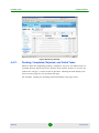
List Menu Options
After selecting a device from the device table, the Device Info page is displayed and
the List menu options are enabled (Figure 41).
The List menu contains the following options (detailed in the next sections) for the
selected device:
Device Info
Device Settings
Advanced View
Device Monitoring
File Download
File Upload
Custom RPC
Device History
Device Activity
Task Information:
6.4.1
»
Pending tasks
»
Completed tasks
»
Rejected tasks
»
Failed tasks
Device Info
The Device Info option opens the Device Info page (Figure 41), which displays
general device parameters including manufacturer, OUI, model, description, serial
number, hardware version, firmware version, up time, notification about changes
done to the device, a link to the local web page of the device, and a list of methods
supported by the device.
StarACS
52
User Manual
Updating a CPE
List Menu Options
The controls that are available on the Device Info page are device specific and
differ for the different devices. The following controls are available:
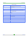
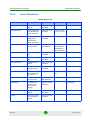
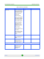
Table 3: Device Info Controls
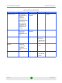
BreezeMAX
1000 CPEs
BreezeMAX
5000 CPEs
BreezeMAX
2000, 3000
and 4000
CPEs
NG_VG *
Control
Description
Reboot Device
Reboots the device
Yes
Yes
Yes
Factory Reset
Resets the device parameters to the
factory default settings
No
Yes
Yes
Create Template
Creates a template for the device (a
prerequisite for creating a new CPE profile.
See also “Creating a New CPE
Yes
Yes
Yes
Profile” on page 40
Delete
Deletes the device from the system
Yes
Yes
Yes
Full Scan
Searches all the base stations that have
connected the CPE
Yes
No
No
Short Scan
Scans by a frequency table
Yes
No
No
Clear Stats
Clears statistics
Yes
No
No
Get Current
This is active when Configuration was
Changed is set as true. Pressing this
control button sets Configuration was
Changed to false and the list of all
parameters is retrieved from the device.
Yes
No
No
Run from
Shadow
Performs Run from Shadow .
No
Yes
No
Set as Main
If the software version is running from
shadow, performs Set as Main .
No
Yes
No
Recheck Status
Rechecks the device status (Note: To
conserve system resources, use this
control sparingly)
Yes
Yes
Yes
Start Trace
Enables monitoring of SOAP traffic
between the CPE and StarACS.
Note: Monitoring stops automatically after
one hour.
Yes
Yes
Yes
Show Trace
Shows the SOAP traffic between the CPE
and StarACS
Yes
Yes
Yes
Ping
Pings the CPE to test its reachability
StarACS
53
User Manual
Updating a CPE
List Menu Options
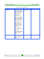
Table 3: Device Info Controls
BreezeMAX
1000 CPEs
Control
Description
Trace Route
Traces the route and displays the hops to
the CPE
BreezeMAX
5000 CPEs
BreezeMAX
2000, 3000
and 4000
CPEs
NG_VG *
NOTE
*The NG_VG is a device that connects physically behind the CPE at the customer location. The
Device Info page includes a parameter with a link between the NG_VG device and the associated
CPE. The parameter is called Associated CPE on the Device Info page of the NG_VG and
Associated NG_VG in the Device Info page of the CPE. The Associated NG_VG parameter is not
a real parameter and is created by the ACS based on the parameter in the voice gateway in order to
facilitate browsing between the two associated devices.
6.4.2
Device Settings
The Device Settings page displays device parameters and enables their
configuration. The device parameters are organized by group tabs, such as
Management Server, Services, WAN Device, LAN Device, Authentication. The tabs
vary depending on the CPE model, and for different models, different tabs are
displayed. It is only a sub-set of parameters; the full list is in the Advanced View
(see “Advanced View” on page 56). For information about parameters, see “Device
Dependent Configuration” on page 134.
The following controls are available on the Device Settings page:
Send Update - sends the update to the device
Get Current - retrieves the current value of the device parameters
To edit parameters in a group of settings:
1
Click the parameter group tab. The parameter group table is displayed. The
relevant device parameters are enabled for editing.
StarACS
54
User Manual
Updating a CPE
List Menu Options
Figure 42: Device Settings
2
Edit the desired parameter values. Refer to “Device Dependent Configuration”
on page 134.
3
Select the control options. The following controls are available:
»
Request device to connect - sends a request to the device to connect and
receive the updated parameters for immediate execution of the required
configuration/action
»
Wait for the next device connection - updates the device parameters on the
next periodic connection initiated by CPE automatically (when periodic
informing is enabled)
»
Add to provision - controls which parameters are added to provisioning for
each device together with the parameters in the CPE Profile.
»
Send Update - sends the update to the device
»
Get Current - retrieves the current parameter values
»
Add Object - creates a new instance of a multi-instance object, a collection
of parameters and/or other objects for which multiple instances are
defined
»
StarACS
Delete Object - deletes an instance of a multi-instance object
55
User Manual
Updating a CPE
6.4.3
List Menu Options
Advanced View
The Advanced View page displays all the parameters in the TR-069 tree and
enables parameter configuration. For detailed information about device dependent
parameters see Section 14 (“Device Dependent Configuration” on page 134).
The following controls are available on the Advanced View page:
Send Update - sends the update to the device
Get Current - retrieves the current value of the device parameter
Add Object -creates a new instance of a multi-instance object, a collection of
parameters and/or other objects for which multiple instances are defined
Delete Object -deletes an instance of a multi-instance object - check whether
these are ever displayed
Figure 43: Typical Advanced View Page
6.4.3.1
Edit Tree
The Edit Tree feature enables limiting the number of parameters that are
requested from a CPE when it registers the network. When a CPE profile reapplies
to a set of CPEs, if the option Request full data tree from existing CPEs is selected,
only those parameters that were checked in the tree will be retrieved. By selecting
StarACS
56
User Manual
Updating a CPE
List Menu Options
only important parameters to be retrieved upon discovery and reprovisioning, the
load on the network is reduced. Even if the option is changed on a specific CPE, it
applies to all CPEs of that Manufacturer and Model Name.
To edit parameters in the tree:
1
Select The Edit Tree control option. The following page is displayed:
Figure 44: Edit Tree
2
Select the desired parameter group by clicking the corresponding tree branch
in the left pane. Drill down the tree if necessary.
3
Edit the selected parameter values. To view the complete object name of the
parameter, point the mouse to the parameter name in the table.
4
StarACS
Select the control options. The following controls are available:
»
Cancel
»
Store Tree - saves the selection and exits the edit mode
»
Clear Tree - clears all the previously selected options
57
User Manual
Updating a CPE
6.4.4
List Menu Options
Provision Manager
The Provision Manager displays all the parameters that are sent to the CPE for
reprovisioning. These are the parameters that were marked to “Add to provision”
in the Device Setting page (Section 6.4.2).
Figure 45: Provision Manager
To edit the provisioning parameters from the Provision Manager:
1
In the Provision Manager, click Edit.
2
Select the parameters to edit.
3
Change the value for these parameters.
4
Click Save.
To remove parameters from the Provision Manager:
StarACS
1
In the Provision Manager, click Edit.
2
Select the parameters to delete.
58
User Manual
Updating a CPE
List Menu Options
1
6.4.5
Click Delete.
Device Monitoring
The Device Monitoring option opens the Device Monitoring page, which displays
the parameters that can be monitored for the particular device.
The following controls are available on the Device Monitoring page:
Start - retrieves counters for selected parameters at a defined interval (default
30000 ms) for as long as the page remains open.
Stop - stops the counters for the selected parameters
Refresh - retrieves counters for selected parameters one time only
To retrieve counters:
1
Select the check-box(es) for the counters, or select the top check-box to select
all the parameters.
2
Click Start. A task is sent to retrieve the information and a hyperlink to a
graph showing the counters over time is displayed in the Graph column once
the first task has been completed.
StarACS
59
User Manual
Updating a CPE
List Menu Options
Figure 46: Device Monitoring Page
3
Click the Graph hyperlink for a particular parameter to display the counters
for this paramater over time.
Figure 47: Graph showing values of parameter over time
StarACS
60
User Manual
Updating a CPE
6.4.6
List Menu Options
File Download
The File Download option opens the File Download page, which enables
downloading firmware image or vendor configuration files to the CPE device.
The firmware image file must be uploaded to the TFTP/HTTP server prior to
executing the firmware update. Once the image file has been uploaded, you need
to supply the location to access the image file on the TFTP/HTTP to be used by the
CPE.
NOTE
For details about the file download configuration for a specific device refer to Section 14.
The following fields are available on the File Download page:
File type - drop down selection menu of the type of file. The possible file types
are Firmware Image, Web Content (currently not applicable) and Vendor
Configuration File
Select file location - drop down selection menu of the location of the file. The
possible values are From list, Manually and Restore (for Vendor Configuration
File type only).
The following controls are available on the File Download page:
Send Update - sends the file update to the CPE
Cancel - cancels the action
StarACS
61
User Manual
Updating a CPE
List Menu Options
Figure 49: File Download Page
To update a file:
1
Select the File type from the drop down list.
2
Modify the following parameters as required:
Table 4: File Download Parameters
Parameter Name
Description
Range
File type
The type of file used for download
Firmware Image Vendor
Configuration File
Description
Description of the current file
Optional value
Select file location
Select the location from where the
file will be downloaded
From list
Manually
Restore (for Vendor
Configuration File)
StarACS
62
User Manual
Updating a CPE
List Menu Options
Table 4: File Download Parameters
Parameter Name
Description
File name
The name of the file as it appears in
File Management
Url
The URL for the file transfer server
Device dependent value
Target location
The target location for the file
transfer server
Device dependent value
User Name
User Name for the file transfer
server
Leave empty
Password
Password for the file transfer server
Leave empty
File size
File Size in KB
File Size in KB
3
Range
Select the file location.
If you chose From list, Figure 50 is displayed:
NOTE
In order to use this option the following conditions should be met:
1. The File Server settings should be according to current CPE type (see Section 4.8).
2. The file to be downloaded should be loaded to the StarACS file system (see Section 11).
Figure 50: Select File from List
StarACS
63
User Manual
Updating a CPE
List Menu Options
a
Select the File name from the list. (The list can be modified in the File
Management area of the application.)
b
Leave the Target location field empty.
If you chose Manually, the following page is displayed:
Figure 51: Manual File Selection
a
Enter the URL from which the file is downloaded (the values are CPE
dependent).
b
Enter a Description (optional).
If you chose Restore (Vendor configuration file only), the following page is
displayed:
StarACS
64
User Manual
Updating a CPE
List Menu Options
Figure 52: Restore Vendor Configuration File
4
6.4.7
a
Select the File name from the list.
b
Leave the Target locationfield empty.
Click Send Update. The firmware update request is sent.
File Upload
The File Upload page enables uploading CPE vendor files to the file server.
The following fields are available on the File Upload page:
File Type - selects the type of file. The possible file types are Vendor
Configuration File and Vendor Log File (not applicable for all Alvarion CPEs).
Select target type - select the target destination of the file. The possible values
are Default site and Manually enter URL.
The following controls are available on the File Upload page:
Send Update - sends the file update
Cancel - cancels the action
StarACS
65
User Manual
Updating a CPE
List Menu Options
Figure 53: File Upload Page
To upload a file:
1
Select the File type from the list.
2
Modify the following parameters as required:
Table 5: File Upload parameters
Parameter Name
Description
Range
File type
The type of file used for upload
Vendor Configuration File
Description
Description of the current file
Optional Value
Select target type
Select the location to where the file
will be uploaded
Default Upload URL
Manually enter URL
Destination URL
The URL for the file transfer server
User Name
User Name for the file transfer
server
Password
Password for the file transfer server
StarACS
66
CPE dependent value
User Manual
Updating a CPE
List Menu Options
3
Specify how to find the target destination: Default upload URL or Manually
enter URL.
4
Enter the file name.
»
If you chose Default upload URL, the following page is displayed:
Figure 54: File Upload - Default Site
»
StarACS
If you chose Manually enter URL, the following page is displayed:
67
User Manual
Updating a CPE
List Menu Options
Figure 55: File Upload - Manually Enter URL
a
5
6.4.8
Enter the destination URL (the values are CPE dependent).
Click Send Update. The file is uploaded to the target destination.
Custom RPC
The Custom RPC option displays the Custom RPC page. It enables manually
configuring commands and sending them to the device. This is useful for
debugging CPEs or for sending methods that are not supported by StarACS to the
device. All methods supported by the device can be used.
The following fields are available on the Custom RPC page:
Method name - selects the RPC Method supported by the CPE. The
information is retrieved directly from the CPE as a response to the method
sent to Get RPC Methods on discovery.
Request - contains the SOAP message from the SOAP Body element.
The following controls are available on the Custom RPC page:
Send Update - sends the command to the device
StarACS
68
User Manual
Updating a CPE
List Menu Options
Cancel - clears the screen without sending the configured information to the
device
Figure 56: Custom RPC Page
6.4.9
Device History
The Device History option opens the Device History page. The Device History page
displays recorded events for the device for 48 hours from the last inform received.
The following fields are available on the Device History page:
Show all - displays all events
Show by date - displays events that occurred on a specific date
Activity Type - select to view only the events of a certain type
The following controls are available on the Device History page:
Refresh - refreshes the page
Delete - deletes all the events in the current view
Save - opens or downloads an xls file with all the events listed
StarACS
69
User Manual
Updating a CPE
List Menu Options
Figure 57: Device History
6.4.10
Device Activity
The Device Activity option opens the Device Activity page, which displays selected
tasks for the device executed on specified dates.
The following fields are available on the Device Activity page:
Show all - displays all tasks
Show by date - displays tasks that occurred on a specific date
Task type - selects the task type
Task method - selects the task method
The following controls are available on the Device Activity page:
Refresh - refreshes the display
Delete - deletes selected tasks
StarACS
70
User Manual
Updating a CPE
List Menu Options
Figure 58: Device Activity
6.4.11
Pending, Completed, Rejected, and Failed Tasks
Shortcut links for displaying pending, completed, rejected, and failed tasks are
available directly below the Device Activity menu option. If there is at least one
task in the category, a shortcut link is provided. Clicking the link displays the
Device Activity page for the specified task type.
For example, clicking the Pending tasks link displays the page below:
StarACS
71
User Manual
Updating a CPE
List Menu Options
Figure 59: Pending, Completed, Rejected, and Failed Tasks
Failed task entries are color-coded pink. The error code is displayed as a tool tip
when the mouse hovers over the failed task (see Table 6).
Table 6: Error Codes
Fault code
Description
TR-069 predefined error codes
0
No Fault
9000
Method not supported
9001
Request denied (no reason specified)
9002
Internal error
9003
Invalid arguments
9004
Resources exceeded (when used in association with SetParameterValues,
this MUST not be used to indicate parameters in error)
9005
Invalid parameter name
9006
Invalid parameter type (associated with SetParameterValues)
9007
Invalid parameter value (associated with SetParameterValues)
StarACS
72
User Manual
Updating a CPE
List Menu Options
Table 6: Error Codes
Fault code
Description
9008
Attempt to set a non-writable parameter (associated with
SetParameterValues)
9009
Notification request rejected (associated with SetParameterAttributes
method)
9010
Download failure (associated with Download or TransferComplete methods)
9011
Upload failure (associated with Upload or TransferComplete methods)
9012
File transfer server authentication failure (associated with Upload, Download,
or TransferComplete methods)
9013
Unsupported protocol for file transfer (associated with Upload and Download
methods)
Vendor Specific: File Transfer 9800-9819
9800
Incorrect File Type parameter
9801
Can not resolve URL of TFTP server
9802
Invalid Target File Name
9803
Invalid File Size
9804
TFTP failed, Corrupted File Format
9805
Configuration File Invalid
9806
MD5 Check Failed
Vendor Specific: AddObjectResponse 9820-9829
9820
Max services exceeded
9821
Instance Already Exist
StarACS
73
User Manual
Updating a Group of CPEs
7.
Viewing CPE Groups
Updating a Group of CPEs
The Update Group page enables applying parameters to a group of CPE devices of
the same manufacturer and model. The Update Group menu enables the following
options:
“Viewing CPE Groups” on page 74
“Importing a File for Updating a Group” on page 79
“Creating a New CPE Group” on page 80
“Defining a Filter Group” on page 83
7.1
Viewing CPE Groups
Click the View menu option to display a table of CPE update groups:
Figure 60: Update Group - View
The table may be filtered by:
Manufacturer
Model name
StarACS
74
User Manual
Updating a Group of CPEs
Viewing CPE Groups
Update status - the update status of the group profile. The possible values are:
»
All - all groups are displayed (no filtering)
»
Active - CPE groups that are still in the update process are displayed
»
Not active - only non-active groups are displayed
»
Scheduled - pending CPE groups that are scheduled for update in the
future are displayed
»
Running - CPE groups that were scheduled and are currently in the update
process are displayed
»
Error - groups whose update process failed are displayed
The table displays the following fields:
Name - CPE update group name
Manufacturer - CPE manufacturer
Model - CPE model name
Created - CPE update group creation date and time
Start Date - date when group was created
Creator - username who created the CPE update group
Version - CPE update group version number
Entries are color-coded as follows:
Active - blue
Non-active - gray
Errors - pink
Running - yellow
The following actions are available:
StarACS
75
User Manual
Updating a Group of CPEs
Viewing CPE Groups
Sort - sorts the table by the selected field
Edit - edits the selected update group
Export - exports the selected update group in xml format
Activate - activates the selected update group
Delete - deletes the selected update group
Stop - stops a task that is running
To sort the update group table by a field:
Click the selected field name in the update group table header row. The update
group table is sorted by the selected field in ascending order (▲). To sort in
descending order (▼), click the selected field name again.
To export an update group:
Click Export for the selected group profile entry in the table. A dialog box prompts
if to open or save the profile file in xml format.
To activate an update group:
1
Check the box in the row for the selected group profile entry in the table.
2
Select whether the profile is to be activated immediately by requesting the
device to connect or later by waiting for the next device connection.
3
Click Activate. The group profile is activated and the table row is color-coded
blue.
NOTE
Once activated, CPE groups can not be deactivated. They remain active for logging purposes and
to maintain the polling configuration of specific parameters.
StarACS
76
User Manual
Updating a Group of CPEs
Viewing CPE Groups
To delete an update group:
1
Check the box in the row for the selected group profile entry in the table.
2
Click Delete. The group profile is deleted.
NOTE
As soon as a CPE group is deleted, the polling that was activated for specific parameters ceases,
but the information already collected remains in the device_stats table in the database.
To stop an update group:
1
Check the box in the row for the selected group profile entry in the table.
2
Click Stop. The update for the group is stopped.
NOTE
Only running groups can be stopped.
To edit an update group:
NOTE
Only non-active groups can be edited.
1
Click any field in the row of the selected entry in the table. The group profile
parameter table is displayed.
StarACS
77
User Manual
Updating a Group of CPEs
Viewing CPE Groups
Figure 61: Group Profile Parameter Table
2
Select whether to activate the group profile immediately or schedule its
activation at a later date and time.
3
Select the recipients of the file. The possible values are:
»
All - sends to all recipients
»
Individual - sends to individuals only
»
Import from file - sends to recipients listed in the imported file. The file
must have the following format:
<?xml version="1.0"?>
<Devices>
<Device>serial_number1</Device>
<Device>serial_number2</Device>
</Devices>
»
Group Name - all new filtering groups that are created (using the Edit
Group or Create Group buttons) are displayed in the drop-down list
NOTE
If Individual or Import from file are selected, the Select Devices option becomes available. This
enables to select from all the CPEs in the network or to import a file with a predefined list of CPEs.
The list of CPEs is displayed in the Devices tab.
StarACS
78
User Manual
Updating a Group of CPEs
4
Importing a File for Updating a Group
Enter one or two time periods for CPE updates (optional). This feature enables
selecting a specific time interval every day, in which to perform the update.
5
Enter the number of CPEs to be updated in the Amount field and the time
interval (in minutes) between updates for the particular period.
6
Enter the number of devices after which testing should be paused in the Pause
after field. For example; if you want to test a new update group on only 10
devices, enter 10 in the Pause after field. The update will stop after updating
the first 10 devices once only. If the Stop on pause field is checked, the update
will pause each time after updating 10 devices.
7
Click the parameter group tab (Management Server, etc.).
8
Edit the parameter values.
9
To periodically sample the selected parameter, check the Polling box. The
information is stored in the device_stats table in the database.
10 To manually configure commands for a group of CPEs, click the Actions tab.
The controls that can be configured are device specific and differ for the
different devices. Refer to Table 3 for information about the controls that are
available for each type of device.
11 To send the files to the CPE, click Download file.
12 To view the entire parameter-tree, click Advanced View.
13 Select whether to activate the update group actively or passively by choosing
Request device to connect or Wait for the next device connection.
14 To save the profile without activating it, click Save. To save the profile and
activate it, click Save and Activate. The update group is saved. If activated, the
table row is color-coded blue.
NOTE
The Device ‘x’ group parameter tab shows the list of CPEs to which the group applies and the
update status for each of the CPEs in the group. The ‘x’ indicates the number of CPEs in the group.
For example; if there are 10 CPEs in the group, the tab will be called Device 10.
7.2
Importing a File for Updating a Group
To import an update file :
1
Click the Import menu option to import an update group. The following page is
displayed:
StarACS
79
User Manual
Updating a Group of CPEs
Creating a New CPE Group
Figure 62: Update Group - Import
7.3
2
Enter the file name or click Browse to select the file to import.
3
Click Open. The imported group parameters are displayed.
Creating a New CPE Group
To create a new CPE group you need to first create a template for the CPE model.
To create a new group:
1
StarACS
Click the New menu option. The following page is displayed:
80
User Manual
Updating a Group of CPEs
Creating a New CPE Group
Figure 63: Create a New Update Group - 1
2
Select the Manufacturer and Model name. The following page is displayed:
Figure 64: Create a New Update Group - 2
3
Enter a name for the group.
4
Select whether to activate the group profile immediately or schedule its
activation at a later date and time.
StarACS
81
User Manual
Updating a Group of CPEs
5
Creating a New CPE Group
Select the recipients of the file. The possible values are:
»
All - sends to all CPEs matching the selected manufacturer and model
name
»
Individuals - sends to individual CPEs that are chosen from the list of
CPEs matching the selected manufacturer and model name
»
Import from file - sends to recipients listed in the imported file. The file
must have the following format:
<?xml version="1.0"?>
<Devices>
<Device>serial_number1</Device>
<Device>serial_number2</Device>
</Devices>
»
Group Name - all new filtering groups that have already been created and
defined (using the Edit Group or Create Group buttons) are displayed in
the drop-down list (see Section 7.4 for details on creating a filter group)
6
Enter one or two time periods for CPE updates (optional).
7
Enter the number of CPEs to be updated in the Amount field and the time
interval (in minutes) between updates for the particular period .
8
Enter the number of devices after which testing should be paused in the Pause
after field. For example; if you want to test a new update group on only 10
devices, enter 10 in the Pause after field. The update will stop after updating
10 devices once only. If the Stop on pause field is checked, the update will
pause each time after updating 10 devices.
9
Click the parameter group tab (Management Server, etc.).
10 Edit the parameter values.
11 To periodically sample the selected parameter, check the Polling box. The
information is stored in the device_stats table in the database.
12 To manually configure commands for a group of CPEs, click the Actions tab.
The controls that can be configured are device specific and differ for the
different devices. Refer to Table 4 for information about the controls that are
available for each type of device.
13 To send the files to the CPE, click Download file.
14 To view the entire parameter-tree, click Advanced View.
StarACS
82
User Manual
Updating a Group of CPEs
Defining a Filter Group
15 Set the order in which the rows should be sorted and click Finish. The
selected parameters will be displayed in the list of groups.
16 Select whether to activate the update group actively or passively by choosing
Request device to connect or Wait for the next device connection.
17 To save the profile without activating it, click Save. To save the profile and
activate it, click Save and Activate. The update group is saved and the name of
the group appears in the list of recipients who can receive the file . If activated,
the table row is color-coded blue.
7.4
Defining a Filter Group
1
Click Create group. The Create new group page is displayed.
Figure 65: Create a New Filter Group - 1
2
Enter a name for the group and click Next. The Filter records page is
displayed.
StarACS
83
User Manual
Updating a Group of CPEs
Defining a Filter Group
Figure 66: Create a New Filter Group - 2
3
Click Add Filter to add filters and click Next. The Set Filter page is displayed.
Figure 67: Create a New Filter Group - 3
4
StarACS
Enter filter criteria:
84
User Manual
Updating a Group of CPEs
a
Defining a Filter Group
In the Column name field, select a criterion from the drop down list; for
example, IP Address. The Compare field opens.
b
In the Compare field, select a delimiter (the available delimiters depend on
the selected criterion):
◊ None: use to match an empty field for the selected criterion (in the
example, CPEs with no IP Address)
◊ = : use to match an exact string for the selected criterion (in the
example, a full IP Address: 192.168.1.2)
◊ != : use to match strings that are different from the specified string
◊ Like: use to match a string anywhere in the selected criterion (in the
example, IP Addresses containing 68)
◊ No Like: use to match string that do not contain the specified string
anywhere in the selected criterion (in the example, IP Addresses not
containing 68)
◊ Is null: use to match an empty field for the specified criterion
◊ Is not null: use to match any field for the specified criterion that is not
empty.
◊ Starts with: use to match a string matching exactly the beginning of the
selected criterion (in the example, the beginning of the IP Address:
192.168)
◊ The Created/Updated criteria fields include additional options relating
to the date of creation/update:
•
On day - use to specify a specific creation/update date and
optionally time of day
•
Prior to - use to specify any date before the selected date and
optionally time of day
•
Later than - use to specify any date after the selected date and
optionally time of day
StarACS
•
Today - use to specify today’s date
•
Before today - use to specify any date before today
•
Yesterday - use to specify yesterday as the creation/update date
85
User Manual
Updating a Group of CPEs
Defining a Filter Group
•
Prev 7 days - use to specify the creation/update day in the last 7
days (excluding today)
•
Prev X days - use to specify the creation/update day in the last X
days (where X is any number, excluding today)
c
In the Input text field, enter the string to match the required criterion.
d
Click Next. The new filter criterion is displayed.
e
Add more filter criteria as necessary by repeating steps 3 and 4. Include
the And/Or logic.
f
5
StarACS
When all filter criteria are set, click Finish.
You can select the filter group in the Send to field.
86
User Manual
Monitoring
8.
Viewing Events
Monitoring
The Monitoring page enables monitoring events that show the state of the CPE
and/or selected parameters. The Monitoring menu enables the following options:
“Viewing Events” on page 87
“Importing an Event Monitoring File” on page 92
“Creating a New Event” on page 94
“Viewing an Event Log” on page 96
8.1
Viewing Events
Click the View menu option to display a table of events that are being monitored:
Figure 68: Monitoring - View
The table may be sorted by:
Manufacturer
StarACS
87
User Manual
Monitoring
Viewing Events
Model name
Name
State
Updated
The table displays the following fields:
Manufacturer - CPE manufacturer
Model name - CPE model name
Name - the name of the event
State - the state of the event. The possible values are:
»
Inactive
»
Completed
»
Scheduled
»
Running
»
Executing
»
Error
Export - exports the selected event in xml format
Updated - the date that the event was last updated
Entries are color-coded as follows:
Active - blue
Non-active - gray
Errors - pink
Running/Scheduled/Executing - yellow
StarACS
88
User Manual
Monitoring
Viewing Events
The following actions are available:
Activate - activates the selected event
Delete - deletes the selected event
Refresh - refreshes the current view
Stop - stops a task that is running
To sort the events by a field:
Click the selected field name in the Event Monitoring table header row. The Event
Monitoring table is sorted by the selected field in ascending order (▲). To sort in
descending order (▼), click the selected field name again.
To export an event:
Click Export for the selected event entry in the table. A dialog box prompts if to
open or save the profile file in xml format.
To activate an event:
1
Check the box in the row for the selected event entry in the table.
2
Select whether the event is to be activated immediately by requesting the
device to connect or later by waiting for the next device connection.
3
Click Activate. The group profile is activated and the table row is color-coded
blue.
To delete an event:
StarACS
1
Check the box in the row for the selected event entry in the table.
2
Click Delete. The group profile is deleted.
89
User Manual
Monitoring
Viewing Events
To stop an event:
1
Check the box in the row for the selected event entry in the table.
2
Click Stop. The update for the event is stopped.
NOTE
Only running, scheduled or executing events can be stopped.
To edit an event:
NOTE
Only inactive events can be edited.
1
Click any field in the row of the selected entry in the table. The event
parameter table is displayed.
StarACS
90
User Manual
Monitoring
Viewing Events
Figure 69: Event Parameters Table
2
Check the Monitoring Device State box to enable monitoring of the state of the
CPE. This has the same functionality as the Recheck Status button in Device
info, but from this table, it can be applied to multiple CPEs. Click the View Log
button to view the results once the event has started.
3
Select whether to activate the event immediately or schedule its activation at a
later date and time.
4
Select the devices that will be affected by this event. The possible values are:
»
All - sends to all devices affected by the event
»
Individual - sends to an individual device affected by the event
»
Import from file - sends to the devices listed in the imported file. The file
must have the following format:
<?xml version="1.0"?>
<Devices>
<Device>serial_number</Device>
StarACS
91
User Manual
Monitoring
Importing an Event Monitoring File
<Device>serial_number</Device>
</Devices>
»
Group Name - all new filtering groups that are created (using the Edit
Group or Create Group buttons) are displayed in the drop-down list (see
Section 7.4 for details on creating a filter group)
NOTE
If Individual or Import from file are selected, the Select option becomes available. This enables to
select from all the CPEs in the network or to import a file with a predefined list of CPEs. The list of
CPEs is displayed in the Devices tab.
5
Enter the Date and Time until which the event will be active and the interval
(in minutes) that the event will be performed.
6
Enter a time period for which the event will be monitored. This enables
monitoring the devices only between certain hours during the day.
7
Enter the number of CPEs to be monitored in the Amount field and the time
interval (in minutes) between updates for the particular period.
8
Click the parameter group tab (Management Server, etc.).
9
To periodically sample the selected parameter, check the Polling box. Click the
View Log button to view the results once the event has started.
10 To view the entire parameter-tree, click Advanced View.
11 To save the profile without activating it, click Save. To save the profile and
activate it, click Save and Activate. The event is saved. If activated, the table
row is color-coded blue.
8.2
Importing an Event Monitoring File
To import an event monitoring file :
1
StarACS
Click the Import menu option. The following page is displayed:
92
User Manual
Monitoring
Importing an Event Monitoring File
Figure 70: Event Monitoring - Import
StarACS
2
Enter the file name or click Browse to select the file to import.
3
Click Open. The imported group parameters are displayed.
93
User Manual
Monitoring
8.3
Creating a New Event
Creating a New Event
To create a new event:
1
Click the New menu option. The following page is displayed:
Figure 71: Create a New Event - 1
2
StarACS
Select the Manufacturer and Model name. The following page is displayed:
94
User Manual
Monitoring
Creating a New Event
Figure 72: Create a New Event - 2
3
Enter a name and description for the event.Check the Monitoring Device State
box to enable monitoring of the state of the CPE. This has the same
functionality as the Recheck Status button in Device info, but from this table,
it can be applied to multiple CPEs. Click the View Log button to view the
results once the event has started.
4
Select whether to activate the event immediately or schedule its activation at a
later date and time.
5
Select the devices that will be affected by this event. The possible values are:
»
All - sends to all devices affected by the event
»
Individual - sends to an individual device affected by the event
»
Import from file - sends to the devices listed in the imported file. The file
must have the following format:
<?xml version="1.0"?>
<Devices>
<Device>serial_number</Device>
StarACS
95
User Manual
Monitoring
Viewing an Event Log
<Device>serial_number</Device>
</Devices>
»
Group Name - all new filtering groups that are created (using the Edit
Group or Create Group buttons) are displayed in the drop-down list (see
Section 7.4 for details on creating a filter group)
NOTE
If Individual or Import from file are selected, the Select option becomes available. This enables to
select from all the CPEs in the network or a import a file with a predefined list of CPEs. The list of
CPEs is displayed in the Devices tab.
6
Enter the Date and Time that the event will be active and the interval (in
minutes) that the event will be performed.
7
Enter a time period for which the event will be monitored. This enables
monitoring the devices only between certain hours during the day.
8
Enter the number of CPEs to be monitored in the Amount field and the time
interval (in minutes) between updates for the particular period.
9
Click the parameter group tab (Management Server, etc.).
10 Edit the parameter values. All parameters for the device are visible.
11 To periodically sample the selected parameter, check the Polling box. Click the
View Log button to view the results once the event has started.
12 To view the entire parameter-tree, click Advanced View.
13 Click New group to create a new filter group. (see Section 7.4 for details on
creating a filter group).
14 To save the profile without activating it, click Save. To save the profile and
activate it, click Save and Activate. The event is saved. If activated, the table
row is color-coded blue.
8.4
Viewing an Event Log
Once a monitoring task starts, it is possible to view the status of the task over a
period of time. The log displays the status of the CPEs (online/offline) or/and
parameters values depending on what was selected when creating the Event,
StarACS
96
User Manual
Monitoring
Viewing an Event Log
To view an event log:
1
Select the event from the Event Monitoring table.
2
Click the View Log button at the bottom of the event page. The following page
is displayed:
Figure 73: View Log
3
Enter the dates for which you want to view the event log.
4
Select the type of log. It is possible to view a log showing the state of the device
or for a parameter.
5
Click Open report to view the events over the time period specified or click
Export to export the results to a .csv file.
StarACS
97
User Manual
Events
9.
Viewing Events
Events
The Events page enables defining, viewing and handling of events. Events are
triggers that can be sent to external systems when the configured conditions are
met. The Events menu enables the following options:
“Viewing Events” on page 98
“Importing an Event File” on page 102
“Creating a New Event” on page 104
9.1
Viewing Events
Click the View menu option to display a table of events.
Figure 74: Events - View
The table may be sorted by:
Manufacturer
Model name
The table displays the following fields:
StarACS
98
User Manual
Events
Viewing Events
Manufacturer - CPE manufacturer
Model name - CPE model name
Name - the name of the event
State - the state of the event. The possible values are:
»
Inactive
»
Completed
»
Scheduled
»
Running
»
Error
Export - exports the selected event in xml format
Updated - the date and time that the event was last updated
Entries are color-coded as follows:
Inactive - white
Completed - blue
Running/Scheduled - yellow
Errors - pink
The following actions are available:
Sort - sorts the table by the selected field
Edit view - edits the selected view
New view – creates a custom view
Activate - activates the selected event
Deactivate - deactivates the selected event
StarACS
99
User Manual
Events
Viewing Events
Delete - deletes the selected event
Refresh - refreshes the display
Stop - stops a task that is running
To sort the events by a field:
Click the selected field name in the Event table header row. The Event table is
sorted by the selected field in ascending order (▲). To sort in descending order
(▼), click the selected field name again.
To create a custom view:
Follow the instructions is Section 6.2 “To edit the view of the CPE list:” on page 48
and “To create a new view of the CPE list:” on page 49.
To export an event:
Click Export for the selected event entry in the table. A dialog box prompts if to
open or save the profile file in xml format.
To activate an event:
1
Check the box in the row for the selected event entry in the table.
2
Click Activate. The group profile is activated and the table row is color-coded
yellow.
To delete an event:
StarACS
1
Check the box in the row for the selected event entry in the table.
2
Click Delete. The group profile is deleted.
100
User Manual
Events
Viewing Events
To edit an event:
NOTE
Only inactive events can be edited.
1
Click any field in the row of the selected entry in the table. The event
parameter table is displayed.
Figure 75: Event Parameters Table
2
Edit the required parameters.
3
Select the devices that will be affected by this event. The possible values are:
»
All - sends to all devices affected by the event
»
Individual - sends to an individual device affected by the event
»
Import from file - sends to the devices listed in the imported file. The file
must have the following format:
<?xml version="1.0"?>
<Devices>
<Device>serial_number</Device>
StarACS
101
User Manual
Events
Importing an Event File
<Device>serial_number</Device>
</Devices>
»
Group Name - all new filtering groups that are created (using the Edit
Group or Create Group buttons) are displayed in the drop-down list (see
Section 7.4 for details on creating a filter group)
NOTE
If Individual or Import from file are selected, the Select option becomes available. This enables to
select from all the CPEs in the network or to import a file with a predefined list of CPEs. The list of
CPEs is displayed in the Devices tab.
4
Select when to activate the event by selecting either Immediately or Scheduled
to.
5
To view the entire parameter-tree, click Advanced View.
6
To save the profile without activating it, click Save. To save the profile and
activate it, click Save and Activate. The event is saved. If activated, the table
row is color-coded yellow.
9.2
Importing an Event File
To import an event file:
1
StarACS
Click the Import menu option. The following page is displayed:
102
User Manual
Events
Importing an Event File
Figure 76: Event Monitoring - Import
StarACS
2
Enter the file name or click Browse to select the file to import.
3
Click Save. The imported group parameters are displayed.
103
User Manual
Events
9.3
Creating a New Event
Creating a New Event
To create a new event:
1
Click the New menu option. The following window is displayed:
Figure 77: Create a New Event - 1
2
StarACS
Select the Manufacturer and Model name. The following window is displayed:
104
User Manual
Events
Creating a New Event
Figure 78: Create a New Event - 2
3
Enter a name and description for the event.
4
From the Send to list, select the group to be notified when the event occurs.
For details on groups, see Chapter 7.
5
Select whether to activate the event immediately or schedule its activation at a
later date and time.
6
Enter the deactivation date and time for the event in the Date to field.
7
Select one of the two main tabs: Parameters or Events. Parameters configures
events based on CPE specific parameters values and Events configures
triggers based on Inform counts.
8
For each desired Parameter name:
a
Select the Condition to be applied to it. The possible values are:
◊ CONTAINS
◊ EQUAL
◊ GREATER
◊ GREATER_EQUAL
◊ LESS
StarACS
105
User Manual
Events
Creating a New Event
◊ LESS_EQUAL
◊ NOT_EQUAL
◊ STARTS_WITH
◊ VALUE_CHANGE.
b
9
Enter the Parameter value to trigger the event.
Save the event:
»
Save: saves the event without activating it
»
Save and Activate: saves the event and activates it. The table row is
color-coded yellow.
StarACS
106
User Manual
Reports
10.
Reports
Click the Reports tab to display the following options:
CPE distribution report
CPE registration report
Pending tasks
Rejected tasks
Activity
Update reports
Figure 79: Reports Window
All of the reports can be printed or exported to a table in a spreadsheet.
StarACS
107
User Manual
Reports
CPE Distribution Report
To print a report:
From the report, click Print Report. A print dialog opens, enabling you to print the
report table.
To export a report:
From the report, click Export Report. A dialog opens, enabling you to open or save
the table as an Excel spreadsheet.
10.1
CPE Distribution Report
Click the CPE distribution report option to enable searching for connection
reports for device by the following parameters:
Manufacturer
The following controls are available:
Show All
Show by specific date. The table that is generated only shows those CPEs that
were registered on the selected date.
StarACS
108
User Manual
Reports
CPE Distribution Report
Figure 80: CPE Distribution Report Window
To display a distribution report:
1
Select the CPE device manufacturer and model from the lists, or specify All.
2
Click Go. The distribution report table for the selected devices is displayed
and the Export Report and Print Report options are enabled.
StarACS
109
User Manual
Reports
CPE Registration Report
Figure 81: CPE Distribution Report
10.2
CPE Registration Report
The Registration report is an inventory report of the CPE, that lists the times when
the last contact with the CPE was created. A CPE cannot be connected but not
registered. However, a CPE can be register but not connected, which is the usual
state.
Click the CPE registration report option to enable searching for registration
reports for devices by the following parameters:
Manufacturer
Model
From Date
To Date
StarACS
110
User Manual
Reports
Pending Tasks Report
Figure 82: CPE Registration Report
10.3
Pending Tasks Report
Click the Pending Tasks option to display reports of pending tasks by the following
parameters:
Manufacturer
Model
From date
A task may be pending for the following reasons:
The task was configured to be executed at next time reconnection
The CPE device is not online (The connection between the ACS and the CPE
device is broken).
StarACS
111
User Manual
Reports
Pending Tasks Report
Figure 83: Pending Tasks Window
Select the Manufacturer, Model, and From date and click Go. The Pending Tasks
table is displayed.
Figure 84: Pending Tasks Table
StarACS
112
User Manual
Reports
10.4
Rejected Tasks Report
Rejected Tasks Report
Rejected task is no response from the CPE on a task, whereas in failed task – the
CPE response about this task is “failed”.
Click the Rejected Tasks option to display reports of rejected tasks by the
following parameters:
Manufacturer
Model Type
From date
Figure 85: Rejected Tasks Window
Select the Manufacturer, Model, and From date and click Go. The Rejected Tasks
table is displayed.
10.5
Activity
Click the Activity option to display activity log reports. The following page is
displayed:
StarACS
113
User Manual
Reports
Activity
Figure 86: Activity Report Window
Activity reports are displayed by the following activity types:
Profiles
Update a CPE
Update Group
System
10.5.1
Profiles Activity Report
The activity report lists all the activities that were performed on profiles, such as:
create, activate, delete, edit a CPE profile or the default profile.
To display profile activity:
1
StarACS
Select Profiles from the Activity log type list. The following page is displayed.
114
User Manual
Reports
Activity
Figure 87: Profiles Window
2
3
Select the specific user or All users.
Select the Activity type. The possible values are All, Create profile, Delete
profile, Edit profile, Import profile, Activate profile, Add firmware, and Delete
firmware.
4
Select the report date range in From date and To date.
5
Click Go. The Profiles activity report is displayed.
Figure 88: Profiles Activity Report
StarACS
115
User Manual
Reports
10.5.2
Activity
Update a CPE Activity Report
To display CPE update activity:
1
Select Update a CPE from the Activity log type list. The following page is
displayed
Figure 89: CPE Update Activity Log
2
Select the specific user or All users.
3
Select the Activity type. The possible values are All, Reset to factory default,
Reboot device, Delete device, Change parameters, Polling add, Polling remove,
Add firmware, Delete firmware, Add object, Delete object, Add file upload,
Delete file upload, Add diagnostic, and Delete diagnostic.
4
Select the report date range in From date and To date.
5
To list results for a specific device, enter the device serial number. Otherwise,
leave blank.
6
StarACS
Click Go. The CPE Update activity report is displayed.
116
User Manual
Reports
Activity
Figure 90: CPE Update Activity Report
10.5.3
Update Group Activity Report
To display CPE Group update activity:
1
Select Update Group from the Activity log type list. The following page is
displayed
StarACS
117
User Manual
Reports
Activity
Figure 91: CPE Group Update Activity Log
2
Select the specific user or All users.
3
Select the Activity type. The possible values are All, Create update, Delete
update, Edit update, Import update, Activate update, Scheduled activate, Add
firmware, EditFirmware, and Delete firmware.
4
Select the report date range in From date and To date.
5
To list results for a specific device, enter the device serial number. Otherwise,
leave blank.
6
StarACS
Click Go. The CPE Group Update activity report is displayed.
118
User Manual
Reports
Activity
Figure 92: CPE Group Update Activity Report
10.5.4
System Activity Report
To display System activity:
1
Select System from the Activity log type list. The following page is displayed.
Figure 93: System Activity Log
StarACS
119
User Manual
Reports
Updates Report
2
Select the specific user or All users.
3
Select the Activity type. The possible values are All, User login, User logout,
Configuring email, Configuring DB, Configuring alert, Create user, Delete
user, and Edit user.
4
Select the report date range in From date and To date.
5
Click Go. The System activity report is displayed.
Figure 94: System Activity Report
10.6
Updates Report
Click the Updates Report option to display reports of updating tasks by the
following parameters:
Manufacturer
Model
All dates
Specific Date
StarACS
120
User Manual
Reports
Updates Report
Figure 95: Updates Window
Select the Manufacturer, Model, All Dates or a specific date and click Go. The
Updates table is displayed.
StarACS
121
User Manual
Reports
Updates Report
Figure 96: Updates Report
StarACS
122
User Manual
File Management
11.
File Management
File Management
In the File Management window you can view managed files or add files. The
settings of the file FTP server are set in the Settings window (see “File Server
Settings” on page 27). If the ACS can not connect to the FTP server configured in
Settings -> File Server, an error message is displayed.
Click the File Management tab to display the following menu options:
File Management
Add
11.1
File Management
Click the File Management menu option to display a table of managed files:
Figure 97: File Management Window
The following fields are available for management:
Manufacturer
StarACS
123
User Manual
File Management
Adding a File to the File Server
Model name
File type - the possible values are All, Firmware Image, and Vendor
Configuration File
The table displays the following fields:
Manufacturer name
Model name
File type
Name
File size
File date
The following controls are available:
Delete - deletes the selected file
Refresh - refreshes the display
11.2
Adding a File to the File Server
Click the Add menu option to add a file to the managed files:
StarACS
124
User Manual
File Management
Adding a File to the File Server
Figure 98: Add File
The following fields are available:
Manufacturer
Model name
File type - the possible values are Firmware Image, Web content, and Vendor
Configuration File
Select file - the file name to add
The following controls are available:
Send Update - updates the managed files with the selected file
Cancel - cancels the selected file from the managed files
StarACS
125
User Manual
File Management
Adding a File to the File Server
To add a file to the managed files:
StarACS
1
Select the file type.
2
Enter the name of the file or click Browse and select it.
3
Click Send Update. The file is added to the managed files.
126
User Manual
CSR
12.
Configuration
CSR
CSR is a StarACS dependent application, operating with the StarACS database
and resources but with a separate security system. This application enables the
customer service representative (CSR) to manage, monitor, and diagnose
customer premises equipment (CPE) complying with the TR-069 protocol.
Depending on security level, the customer service representative can perform the
following tasks:
Diagnose and configure CPEs
Update the firmware version
Upload files from the CPE
Verify the CPE's connectivity status
Reset/Reboot the CPE
Display the CPE's activity log
Perform CPE specific RPC Methods
Manage CSR users
Operate with Reports
Configure the database, upload/download file servers, alerts, email
12.1
Configuration
To configure CSR:
1
Verify that Windows IIS is installed on the computer from which CRS will run.
2
Copy the CSR folder to the IIS root location (by default C:\Inetpub\wwwroot).
3
Assign full permission for the user Everyone to the CSR folder (see Figure 99) if
required by the security settings of the operating system.
StarACS
127
User Manual
CSR
Configuration
Figure 99: Folder Permissions
4
Open the ConnectionStrings.xml file (located in
C:\Inetpub\wwwroot\CSR\XML) and edit it according to the DB configuration
of the ACS server. Select MySQL or Oracle and fill in the proper DB connection
data. Save the file and restart the IIS.
5
Open a web browser, enter the link to the CSR application
(http://ip_address/CSR/Default.aspx) and press Enter. The login window is
displayed.
Figure 100: Login WIndow
StarACS
128
User Manual
CSR
User Management
6
Enter the user name and password (default name and
password:admin/admin) and press Enter or click Login. The Update CPE
window is displayed.
7
From the Settings tab, select the ACS and DB menu option to configure the
connection to the StarACS application (Figure 101). Once the database
connection has been correctly configured, the devices from StarACS can be
reached from Update a CPE menu. The devices can be managed, depending on
the permission assigned to the user.
Figure 101: Settings Window
12.2
User Management
CSR defines three levels of user access to the StarACS resources; admin, csr and
user. Users can be added and/or configured from the User Management menu by
a user with admin permission only.
To add a new user:
From the User Management tab, click Add and enter the parameters for the
user (Figure 102).
StarACS
129
User Manual
CSR
User Management
Figure 102: User Management Window
To modify user settings:
Select the user from the list in the User Management window and modify the
parameters as required.
12.2.1
Admin Access Level
Users with admin permission for the CSR application are different from StarACS
admin users. This section refers to CSR users only.
Users with admin privileges have the rights to access the following main menus:
Update a CPE - the same full access as StarACS (see “Updating a CPE” on
page 44)
User Management - this applies to the CSR only
Reports - See “Monitoring” on page 87. The CSR application only has access
to a limited number of reports.
StarACS
130
User Manual
CSR
User Management
Settings - See “Defining StarACS Settings” on page 15. or operating with
Settings menu please check the section of this manual that explains it. The
CSR application only has access to a limited number of settings.
12.2.2
Csr Access Level
Users with Csr permission have the rights to access the following main menus:
Update a CPE - the same full access as StarACS (see “Updating a CPE” on
page 44)
12.2.3
User Access Level
Users with User permission have the rights to access the following main menus:
Update a CPE - limited access. Access is Read Only and View Filters are not
available.
StarACS
131
User Manual
Default Profile Parameters
13.
Default Profile Parameters
Table 7: Default Profile Parameters
Parameter Name
Description
Range
Default
NMS User Name
User name used to
authenticate the CPE when
making a connection to the
ACS using the CPE WAN
Management Protocol.
N/A
tr069
The user name and
password should be
registered as ACS
users
This user name is used
only for HTTP-based
authentication of the CPE.
NMS Password
Password used to
authenticate the CPE when
making a connection to the
ACS using the CPE WAN
Management Protocol.
N/A
tr069
1=Yes (checkbox
selected)
This password is used only
for HTTP-based
authentication of the CPE.
When read, this parameter
returns an empty string,
regardless of the actual
value.
Keep Alive Enable
Whether or not the CPE
maintains a keep alive
mechanism.
Yes/No
Keep Alive Interval
The duration in seconds of
the interval to wait before
reaching a decision that the
server is no longer
available.
N/A
Connection Request User
Name
User name used to
authenticate an ACS
making a connection
request to the CPE
N/A
StarACS
132
dps
User Manual
Default Profile Parameters
Table 7: Default Profile Parameters
Parameter Name
Description
Range
Default
Connection Request Password
Password used to
authenticate an ACS
making a Connection
Request to the CPE.
N/A
dps
When read, this parameter
returns an empty string,
regardless of the actual
value.
StarACS
133
User Manual
Device Dependent Configuration
14.
BreezeMAX 1000 CPEs
Device Dependent Configuration
This section includes configuration information for the following devices:
“BreezeMAX 1000 CPEs” on page 134
“BreezeMAX 2000 CPEs” on page 160
“BreezeMAX 3000 CPEs” on page 177
“BreezeMAX Si 4000 CPEs” on page 196
“BreezeMAX 5000 CPE” on page 253
“NG_VG” on page 277
14.1
BreezeMAX 1000 CPEs
The following are the parameters and file transfer configurations for Alvarion’s
WiMAX 802.16e 1000 PRO and Si CPEs based on the Rosedale 2 chip.
14.1.1
File Transfer Configurations
Firmware Download:
The required parameter for firmware download is:
URL in the format tftp://ip_addr/version.bz, for example:
tftp://192.168.10.200/su_2_5_1_1015.bz
Configuration File Download:
The required parameter for firmware download is:
URL in the format tftp://ip_addr/config_file, for example:
tftp://192.168.10.200/ SU_PARAMS_2_5_1_1015.xml
Configuration File Upload:
The required parameter for firmware download is:
URL in the format tftp://ip_addr/config_file, for example:
tftp://192.168.10.200/ SU_PARAMS_2_5_1_1015.xml
When operating with File Management, the File Servers: Download server details
and CPE upload server details must be configured with tftp://ip_addr, for
example: tftp://192.168.10.200.
StarACS
134
User Manual
Device Dependent Configuration
14.1.2
BreezeMAX 1000 CPEs
List of Parameters
Table 8: Device Info
Parameter Name
Description
Type
Manufacturer
The manufacturer of
the CPE
String of up to 64
characters
Info Model Name
A string identifying
the particular CPE
model and version
String of up to 64
characters
CPE Pro 2, CPE
Pro 2L, CPE Si 2
Product Variant
Radio Type. A string
identifying the
particular CPE
model and version
String of up to 64
characters
[2X|3X|5X]
Description
A full description of
the CPE device
String of up to
256 characters
Alvarion WiMax
<ProductClass>
<ModelName>
<ProductVariant>
Product Class
Product Class of the
CPE
String of up to 64
characters
BMAX
Serial Number
Serial number of the
CPE
String of up to 64
characters
Hardware Version
Hardware version
number
String of up to 64
characters
Software Version
The software version
currently running
String of up to 32
characters
x.x.x.x
Up Time
Time in seconds
since the CPE was
last restarted
unsignedInt
0 - 4294967295
Sec
Name
A full description of
the CPE device
String of up to
256 characters.
Not Set Yet
Organization
The name of the
organization to
which the CPE
belongs
String of up to 32
characters.
Not Set Yet
Address
The organization’s
address
String of up to 32
characters.
Not Set Yet
Country
The country where
the organization is
located
String of up to 32
characters.
StarACS
135
Range
Default
Alvarion
Not Set Yet
12345678
User Manual
Device Dependent Configuration
BreezeMAX 1000 CPEs
Table 8: Device Info (Continued)
Parameter Name
Description
Type
Manufacturer OUI
Organizationally
unique identifier of
the device
manufacturer.
Represented as a
six hexadecimal-digit
value using all
upper-case letters
and including any
leading zeros. The
value MUST be a
valid OUI
String of up to 64
characters
Spec Version
Represents the
version of the
specification
implemented by the
device
String of up to 16
characters
Shadow Indication
Range
Default
0020D6
1.0
0 - The CPE runs
Main version
1- The CPE runs
Shadow version
Configuration was
Changed
Informs whether the
CPE TR-069
parameters have
been altered
internally and not by
ACS
SmartCard Status
SIM card status
0 - False
1 - True
unsignedInt
0 - Installed
1 - Not Installed
2 - Failed
StarACS
136
User Manual
Device Dependent Configuration
BreezeMAX 1000 CPEs
Table 8: Device Info (Continued)
Parameter Name
Description
Type
Range
Configuration File Name
Name of the vendor
configuration file
according to the
name of the
downloaded file
String of up to 64
characters.
e.g.
SU16e_2_0_6_7
6.xml
Configuration File
Version
A string identifying
the configuration file
version currently
used in the CPE
String of up to 16
characters.
x.x.x.x
YYYY-MM-DDTH
H:MM:SS
Default
Vendor Config File.i
Version Major.Minor.
Configuration File Date
Date and time when
the content of the
current version of
this vendor
configuration file was
first applied by the
CPE
DateTime
Configuration File
Description
A description of the
vendor configuration
file from XML file
String of up to
256 characters.
Main SW File Name
Name of the main
software file
String of up to 64
characters.
e.g.
SU16e_2_0_6_7
6.bz
Version of Main SW
A string identifying
the main software
file version currently
used in the CPE
String of up to 16
characters.
x.x.x.x
Main SW File Date
Date and time when
the content of the
current version of
this main software
file file was first
applied by the CPE
String of up to 40
characters
e.g. Mon Feb 11
10:04:38 2008
Name of the shadow
software file.
String of up to 64
characters.
e.g.
SU16e_2_0_6_7
6.bz
Main SW File
Shadow SW File
Shadow SW File Name
StarACS
137
User Manual
Device Dependent Configuration
BreezeMAX 1000 CPEs
Table 8: Device Info (Continued)
Parameter Name
Description
Type
Range
Version of Shadow SW
A string identifying
the shadow software
file version currently
used in the CPE
String of up to 16
characters.
x.x.x.x
Shadow SW File Date
Date and time when
the content of the
current version of
this shadow software
file was first applied
by the CPE
String of up to 40
characters.
e.g. Mon Feb 11
10:04:38 2008
Default
Table 9: Management Server
Parameter Name
Description
Type
NMS User Name
The Username used
to authenticate the
CPE when making a
connection to the
ACS using the CPE
WAN Management
Protocol (used only
for HTTP-based
authentication).
String of up to
256 characters.
tr069
NMS User Password
The Password used
to authenticate the
CPE when making a
connection to the
ACS using the CPE
WAN Management
Protocol (used only
for HTTP-based
authentication).
String of up to
256 characters.
tr069
Periodic Inform Enable
Enables to set
whether or not the
CPE must
periodically send
CPE information to
the Server using the
Inform method call.
Boolean
StarACS
Range
0 - Disable
Default
1
1 - Enabled
138
User Manual
Device Dependent Configuration
BreezeMAX 1000 CPEs
Table 9: Management Server (Continued)
Parameter Name
Description
Type
Periodic Inform Interval
The duration in
seconds of the
interval for which the
CPE must attempt to
connect with the
ACS and call the
Inform method.
Functional only if the
Periodic Inform
Enable parameter is
enabled (checked).
unsignedInt
Periodic Inform Time
An absolute time
reference in UTC to
determine when the
CPE should initiate
the Inform method
calls. Each Inform
call must occur at
this reference time
plus or minus an
integer multiple of
the Periodic Inform
Interval.
DateTime
Range
Default
86400
YYYY-MM-DDTH
H:MM:SS
0000-00-00T00:00:
0
This parameter will
be read only and set
to zero dateTime
value
(0000-00-00T00:00:
00) indicates that no
particular time
reference is
specified. That is,
the CPE may locally
choose the time
reference, required
only to adhere to the
specified
PeriodicInformInterv
al.
StarACS
139
User Manual
Device Dependent Configuration
BreezeMAX 1000 CPEs
Table 9: Management Server (Continued)
Parameter Name
Description
Type
Range
Default
Parameter Key
The value of the
ParameterKey
argument from the
most recent Set
Parameter Values,
Add Object, or
Delete Object
method call from the
Server. If there have
been no such calls,
this value is empty
String of up to 32
characters.
Connection request URL
HTTP URL for an
ACS to make a
Connection Request
notification to the
CPE,in the form:
http://host:port/path
String of up to
256 characters.
http://Management_
IP_addr_of_CPE:80
82/MAC_address_o
f_cpe
The “host” portion of
the URL MAY be the
IP address for the
management
interface of the CPE
in lieu of a host
name.
Connection Request
Username
Username used to
authenticate an ACS
making a
Connection Request
to the CPE.
String of up to
256 characters.
dps
Connection Request
Password
The password used
to authenticate an
ACS making a
Connection Request
to the CPE.
String of up to
256 characters.
dps
StarACS
140
User Manual
Device Dependent Configuration
BreezeMAX 1000 CPEs
Table 9: Management Server (Continued)
Parameter Name
Description
Type
Range
Default
Upgrades Managed
Indicates whether or
not the ACS will
manage upgrades
for the CPE. If true
(1), the CPE
SHOULD not use
other means other
than the ACS to
seek out available
upgrades. If false
(0), the CPE MAY
use other means for
this purpose.
Boolean
1 - True
0
Specifies whether
the CPE succeeded
or failed to
synchronize to the
local clock used for
loging events with
the network
Boolean
URL for the CPE to
connect to the ACS
using the CPE WAN
Management
Protocol.
String of up to
256 characters.
Network Time
URL
0 - False
0 - Not available
1 - Available
ASCII
representation of
the following text:
http://aaa.bbb.ccc
.ddd/nnn
This parameter
MUST be in the form
of a valid HTTP.
The “host” portion of
this URL is used by
the CPE for
validating the
certificate from the
ACS when using
certificate-based
authentication.
StarACS
141
User Manual
Device Dependent Configuration
BreezeMAX 1000 CPEs
Table 10: Services
Parameter Name
Description
Range
Determines whether the
CPE will act in IP CS or L2
CS
0 - IP
Determines whether the
CPE will act in IP CS or L2
CS.
0 - IP CS
Default
Services
Actual Service Mode
Configured Service Mode
1 - L2 CS
0 - IP CS
1 - L2 CS
The change in settings of
this parameter takes effect
only after reset.
IP CS
VLAN to DSCP Number of
Entries
Number of instances of
VLAN to IPCS rules
(active and inactive rules)
0-7
To add an instance:
1
Click "Add object"
control button to add a
new instance of VLAN
to DSCP. The "Active"
field should be set to 0
(not active).
2
Send a message with
the values for the
fields in the newly
created object.
3
Set the "Active" field to
1 (active). This will
cause the all the fields
of the object to
become 'Read-Only'.
To inactivate or remove
an instance click the
"Delete object" control
button.
To update an object,
delete the existing object
and add a new object.
StarACS
142
User Manual
Device Dependent Configuration
BreezeMAX 1000 CPEs
Table 10: Services (Continued)
Parameter Name
Description
Range
Default
This is a read only field
and is managed by “Add
Object” and “Delete
Object”
0 - Not active
1
In VLAN ID
This is a read only field
and is managed by “Add
Object” and “Delete
Object”
0 - 4095
3
In VLAN Priority
This is a read only field
and the number is
managed by “Add Object”
and “Delete Object”
0-7
0
Out DSCP Start
On UL, in case start=stop
and marking is enabled,
all packets that match the
vlan defined for the rule
will have their DSCP
replaced with
outDSCPstart/stop.
0 - 63
21
VLAN to DSCP.i
Active
1 - Active
On DL, In case start=stop
and marking is enabled
and learnedDSCP is
initialized, the matched
packet will have its DSCP
restored.
In case start != stop or
marking is disabled or
learnedDSCP is not
initialized, the matched
packet will not have its
DSCP restored.
In both cases, the
matched packets will have
Vlan added.
This is a read only field is
managed by “Add Object”
and “Delete Object”
StarACS
143
User Manual
Device Dependent Configuration
BreezeMAX 1000 CPEs
Table 10: Services (Continued)
Parameter Name
Description
Range
Default
Out DSCP End
On UL, in case start=end
and marking is enabled,
all packets that match the
vlan defined for the rule
will have their DSCP
replaced with
outDSCPstart/stop.
outDSCPstart - 63
21
0 - False
1
On DL, In case start=end
and marking is enabled
and InDSCP is initialized,
the matched packet will
have its DSCP restored.
In case start != stop or
marking is disabled or
learnedDSCP is not
initialized, the matched
packet will not have its
DSCP restored.
In both cases, the
matched packets will have
Vlan added.
This is a read only field
and is managed by “Add
Object” and “Delete
Object”
DSCP ReMarking Enabled
StarACS
This is a read only field
and is managed by “Add
Object” and “Delete
Object”.
144
1 - True
User Manual
Device Dependent Configuration
BreezeMAX 1000 CPEs
Table 10: Services (Continued)
Parameter Name
Description
Range
Default
0 - Not Active
1
L2 CS
DSCP to VLAN Number of
Entries
Number of instances of
VLAN to L2 CS rules
(active and inactive rules)
To add an instance:
1 Click "Add object"
control button to add a
new instance of DSCP to
VLAN. The "Active" field
should be set to 0 (not
active).
2 Send a message with
the values for the fields in
the newly created object.
3 Set the "Active" field to 1
(active). This will cause
the all the fields of the
object to become
'Read-Only'.
To inactivate or remove
an instance click the
"Delete object" control
button.
To update an object,
delete the existing object
and add a new object.
DSCP to VLAN
Active
StarACS
This is a read only field
and is managed by “Add
Object” and “Delete
Object”
145
1 - Active
User Manual
Device Dependent Configuration
BreezeMAX 1000 CPEs
Table 10: Services (Continued)
Parameter Name
Description
Range
DSCP Start
On UL, in case start=stop
and marking is enabled,
all packets that match the
vlan defined for the rule
will have their DSCP
replaced with
outDSCPstart/stop.
0 - 63
Default
On DL, In case start=stop
and marking is enabled
and learnedDSCP is
initialized, the matched
packet will have its
DSCPrestored.
In case start != stop
ormarking is disabled or
learnedDSCP is not
initialized, the matched
packet will not have its
DSCP restored.
In both cases, the
matched packets will have
Vlan added.
This is a read only field is
managed by “Add Object”
and “Delete Object”
StarACS
146
User Manual
Device Dependent Configuration
BreezeMAX 1000 CPEs
Table 10: Services (Continued)
Parameter Name
Description
Range
DCSCP Stop
On UL, in case start=end
and marking is enabled,
all packets that match the
vlan defined for the rule
will have their DSCP
replaced with
outDSCPstart/stop.
0 - 64
Default
On DL, In case start=end
and marking is enabled
and InDSCP is initialized,
the matched packet will
have its DSCP restored.
In case start != stop or
marking is disabled or
learnedDSCP is not
initialized, the matched
packet will not have its
DSCP restored.
In both cases, the
matched packets will have
Vlan added.
This is a read only field
and is managed by “Add
Object” and “Delete
Object”
Out VLAN ID
This is a read only field
and is managed by “Add
Object” and “Delete
Object”
0 - 4095
NA
Out VLAN Priority
This is a read only field
and the number is
managed by “Add Object”
and “Delete Object”
0-8
0
DSCP value used in
Uplink direction for all
management traffic
(including DHCP
sessions)
0 - 63
Management
Actual DSCP Marking
StarACS
147
User Manual
Device Dependent Configuration
BreezeMAX 1000 CPEs
Table 10: Services (Continued)
Parameter Name
Description
Range
Default
Configured DSCP Marking
The configured DSCP
value used in Uplink for all
management traffic
(including DHCP
sessions).
0 - 63
6
The entered value will
become the actual value
after reset.
Table 11: WAN Device
Parameter Name
Description
Range
Default
Enables to select the
antenna to be used.
0- External
7- Auto
NDS
Antenna Selection Control
1-6 Internal (front &
rear)
7- Auto
Mobility Mode
Enables/disables fast
mobility.
0 - Fixed / Nomadic
0 - Fixed / Nomadic
1 - Mobile
NDS Parameters
BaseStationSelection
Allowed BS ID
The currently configured
BS ID that is allowed to
communicate with the SU
186.190.0.0.250.206
Allowed BS ID Mask
The currently configured
BS ID mask that is
allowed to communicate
with the SU
00:00:00:00:00:00
Preffered BS ID
The currently configured
BS ID that together with
the Preferred BS ID Mask
define the initial search
range for the best BS.
186.190.0.0.250.206
Preffered BS ID Mask
The currently configured
BS ID Mask that together
with the Preferred BS ID
define the initial search
range for the best BS.
00:00:00:00:00:00
StarACS
148
User Manual
Device Dependent Configuration
BreezeMAX 1000 CPEs
Table 11: WAN Device (Continued)
Parameter Name
Description
Range
Default
Configured Allowed BS ID
Defines the BS ID used
together with the BS ID
Mask to define the range
of BSs that can
communicate with the SU.
6 groups of up to 3
digits each. Each
group range is 0-255.
186.190.0.0.250.206
Configured Allowed BS ID
Mask
Defines the BS ID Mask
used together with the BS
ID to define the range of
BSs that can
communicate with the SU.
6 groups of up to 3
digits each. Each
group range is 0-255.
0.0.0.0.0.0
Configured Preffered BS ID
The BS ID that together
with the Preferred BS ID
Mask define the initial
search range for the best
BS. The SU will select the
best BS within this range.
If no BS is found within
this range, the SU will
continue searching in the
entire range defined by
the BS ID and BS ID Mask
parameters.
6 groups of up to 3
digits each. Each
group range is 0-255.
186.190.0.0.250.206
Configured Preffered BS ID
Mask
The BS ID Mask that
together with the
Preferred BS ID define the
initial search range for the
best BS.
6 groups of up to 3
digits each. Each
group range is 0-255.
0.0.0.0.0.0
The scanning frequency
currently configured
2 - 5 Mhz
6 - Auto
Scanning.1
Scan Bandwidth
3 - 7 Mhz
5 - 10 Mhz
6 - Auto
Start Frequency
The lowest frequency
currently configured
See Table 12
Default values according
to the 2.x or 3.x
Stop Frequency
The highest frequency
currently configured
See Table 12
Default values according
to the 2.x or 3.x
Main Frequency Step
The main frequency step
currently configured
StarACS
149
User Manual
Device Dependent Configuration
BreezeMAX 1000 CPEs
Table 11: WAN Device (Continued)
Parameter Name
Description
Intermediate Frequency Step
The intermediate
frequency steps currently
configured
Configured Scan Bandwidth
Specifies the scanning
frequency that shall
become the actual value
after reset.
Range
Default
2 - 5 MHz;
6 - Auto
3 - 7 MHz;
5 - 10 MHz;
6 - Auto
Configured Start Frequency
Configured Stop Frequency
Configured Main Frequency
Step
Configured Intermediate
Frequency Step
Discrete List Number of Entries
Default values according
to the 2.x or 3.x
The lowest frequency in
the range of frequencies
to be scanned (in MHz)
Depends on the radio
band of the unit. See
The highest frequency in
the range of frequencies
to be scanned (in MHz).
Depends on the radio
band of the unit. See
The Main Scanning Step
that together with the
Intermediate Scanning
Steps define the
frequencies to be scanned
between the Start and
End Rx Frequencies.
5 MHz and 10 MHz:
125 KHz - 5000 KHz
5 MHz and 10 MHz: 2500
KHz
7 MHz: 125 KHz 1750 KHz
7 MHz: 875 KHz
8 steps that define the
frequencies to be scanned
between the Start and
End Rx Frequencies
Depends on CPE
frequency, see
Default values according
to the 2.x or 3.x
Specifies the current
number of discrete
frequencies.
This is a read only field
and the number is
managed by “Add Object”
and “Delete Object”
0 - 10
A discrete frequency (in
kHz)
A valid frequency.
Table 12
Default values according
to the 2.x or 3.x
Table 12
Table 12
Discrete List.i
Frequency
Status
Serving Base Station ID
StarACS
The BS ID of the base
station currently serving
the CPE
150
User Manual
Device Dependent Configuration
BreezeMAX 1000 CPEs
Table 11: WAN Device (Continued)
Parameter Name
Description
Range
Authentication Method
The authentication
method in use
0 - Not authenticated
1 - EAP TLS (future
use)
Default
2 - EAP TTLS
3 - EAP AKA (future
use)
Configured Authentication
Method
Select the authentication
method to be used
0 - Not authenticated
1 - EAP TLS (future
use)
2 - EAP TTLS
3 - EAP AKA (future
use)
Connection List Number Of
Active Entries
Number of connection list
active entries
Channel Frequency
The frequency (in kHz)
that the CPE is tuned in
on
Transmit Power
The current transmit
power [dbm] of the CPE
Bandwidth
The bandwidth currently in
use.
0- 5MHz
1- 7MHz
2- 10MHzy
Selected Antenna
The current antenna
selected.
1-7
Downlink SNR
The SNR of the CPE
(-100) - (+100)
0
Downlink RSSI
The RSSI of the CPE
(-115) - (+50)
0
StarACS
Auto
151
User Manual
Device Dependent Configuration
BreezeMAX 1000 CPEs
Table 11: WAN Device (Continued)
Parameter Name
Description
Range
Default
Max Uplink Rate
The maximum UL rate in
the last 100 frames
interval (There is no
sliding window)
QPSK_1_2 rep 6
Not Set Yet
QPSK_1_2 rep 4
QPSK_1_2 rep 2
QPSK_1_2
QPSK_3_4
16QAM_1_2
16QAM_3_4
64QAM_1_2
64QAM_2_3
64QAM_3_4
64QAM_5_6
Max Downlink Rate
The maximum DL rate in
the last 100 frames
interval (There is no
sliding window)
QPSK_1_2 rep 6
Not Set Yet
QPSK_1_2 rep 4
QPSK_1_2 rep 2
QPSK_1_2
QPSK_3_4
16QAM_1_2
16QAM_3_4
64QAM_1_2
64QAM_2_3
64QAM_3_4
64QAM_5_6
DistanceTo BS
StarACS
The distance of the MS
from the BS in meters.
This value should be
calculated based on the
initial range response
timing offset and should
consider periodic offset
correction.
152
0 - 100000 (meters)
0
User Manual
Device Dependent Configuration
BreezeMAX 1000 CPEs
Table 11: WAN Device (Continued)
Parameter Name
Description
Total Bytes Sent
The total number of bytes
sent over the interface
since the CPE was last
reset.
Total Bytes Received
The total number of bytes
received over the
interface since the CPE
was last reset.
Total Packets Sent
The total number of
packets sent over the
interface since the CPE
was last reset.
Total Packets Received
The total number of
packets received over the
interface since the CPE
was last reset.
Scanned BS ID Number Of
Entries
The number of the BS in
the best AU table (a table
listing all the base stations
in reach of the CPE)
Total Rx Crc 16 Errors
The total number of
downlink received HARQ
sub-bursts in which the
CRC calculated does not
match the CRC that
appears in the sub-burst.
CRC16 only appears in
HARQ enabled
connections.
Total Rx Dropped Packets
The total number of MAC
PDU MS dropped as a
result of inactive downlink
connections (Data and
Management).
Total Rx Hcs Errors
The total number of
downlink received MAC
PDU in which the HCS
(Header Check
Sequence) calculated
does not match the HCS
that appears in the PDU.
StarACS
153
Range
Default
0 - 40
0
User Manual
Device Dependent Configuration
BreezeMAX 1000 CPEs
Table 11: WAN Device (Continued)
Parameter Name
Description
Range
Total Tx Discarded Bytes
The total number of
discarded bytes in TX as a
result of aging in queried
connection..
Total Tx Discarded Packets
The total number of
packets discarded in TX
as a result of aging..
Default
Scanned BS ID
Scanned BS ID.i
Antenna Number
BS ID
Channel BW
Frequency (kHz)
SNR (dB)
Dl Per Rate Counters
Dl Per Rate Counters.i
Mcs Type
Number of Sdu
Ul Per Rate Counters
Ul Per Rate Counters.i
Mcs Type
Number of Sdu
Connection List
Connection List.i
Connection Num
Number of connection
Connection Type
Type of connection
Dl Bytes Received
The number of bytes
received in queried
connection
Ul Bytes Dropped
Ul Bytes Transmitted
StarACS
The number of bytes
transmitted in queried
connection
154
User Manual
Device Dependent Configuration
BreezeMAX 1000 CPEs
Table 12: Radio Types
HW type - Radio type
Frequency range
Power range (Max/Min)
To retrieve center frequency
add/subtract half bandwidth from
bottom/top frequency
2.3GHz ADC
2300000-2360000KHz
ODU:19/-26dBm
IDU:23/-26dBm
2.5GHz ADC
2496000-2690000KHz
ODU:19/-26dBm
IDU:24/-26dBm
5.2GHz ADC
5150000-5350000KHz
ODU: 18/-26dBm
3.3GHz SMI (0.8)
3300000-3400000KHz
ODU:20/-26dBm
IDU:22/-26dBm
3.5GHz SMI (0.8)
3399500-3600000KHz
ODU:20/-26dBm
IDU:22/-26dBm
3.6GHz SMI (0.8)
3600000-3800000KHz
ODU:20/-26dBm
IDU:22/-26dBm
2.XGHz SMI (1.0)
2300000-2700000KHz
All IDU:
Sub-Range 2.3GHz:
For 2.3GHz Sub-Range:
2300000-2360000KHz
3.XGHz SMI (1.0)
Sub-Range 2.5GHz:
For 2.5GHz Sub-Range:
2496000-2690000KHz
24/-26dBm
3300000-3800000KHz
All IDU:
23/-26dBm.
StarACS
155
User Manual
Device Dependent Configuration
BreezeMAX 1000 CPEs
Table 13: LAN Devices
Parameter Name
Description
Range
Default
Link Down
Link Down
LAN Ethernet Interface Config.1
MAC Address
The physical address of
the interface
MAC Address Control Number
The MAC address control
number
Ethernet Actual Port Mode
Ethernet Port Mode
Full / 10
Full / 100
Half / 10
Halfl / 100
Configured Port Mode
Enables to configure the
Ethernet port to
auto-negotiation mode or
to set the duplex and
speed.
0 = 10 Mbps Half
Duplex
4 - Auto
1 = 10 Mbps Full
Duplex
2 = 100 Mbps Half
Duplex
3 = 100 Mbps Full
Duplex
4 = Auto
DREG When Eth Phy Is Off
WAN Up LAN Short Down
When enabled, the unit
will Deregister itself when
Ethernet “down” is
detected
0 - Disabled
Enable/Disables the
Ethernet phy after
wireless link is established
(to cause the host to send
DHCP discover)
0 - Disabled
1 - Enabled
1
1 - Enabled
Statistics
Bytes Sent
StarACS
Total number of bytes
sent over the interface
since the CPE was last
reset
156
User Manual
Device Dependent Configuration
BreezeMAX 1000 CPEs
Table 13: LAN Devices (Continued)
Parameter Name
Description
Range
Bytes Received
Total number of bytes
received over the
interface since the CPE
was last reset
Packets Sent
Total number of packets
sent over the interface
since the CPE was last
reset
Packets Received
Total number of packets
received over the
interface since the CPE
was last reset
Default
LAN Host Config Management
IP Interface.1.
IP Address
IP Address for local Web
provisioning
192.168.254.251
Subnet Mask
Subnet mask for IP
Address of local Web
provisioning
255.255.255.0
Table 14: Authentication
Parameter Name
Description
Range
Default
Domain Name
Default Domain Name
used in TTLS for wimax
authentication.
A string
WiMAX.com
Configured Domain Name
Configured Default
Domain Name used in
TTLS for wimax
authentication. Becomes
the actual value after reset
Any string
WiMAX.com
Username
CPE username used in
TTLS for wimax
authentication.
A string
MAC_address
Configured Username
Configured user name
used in TTLS for wimax
authentication.Becomes
the actual value after
reset.
Any string
MAC_address
StarACS
157
User Manual
Device Dependent Configuration
BreezeMAX 1000 CPEs
Table 14: Authentication (Continued)
Parameter Name
Description
Range
Default
Configured Password
User password used in
TTLS for wimax
authentication. Becomes
the actual value after
reset.
Any string
quickynikynyoky
Table 15: Configure File Format Version
Parameter Name
Description
Range
Default
Major Ver
Major Version No. (Ignore
if VendorConfigFile table
exists.)
unsignedInt
1
Minor Ver
Minor Version No. (Ignore
if VendorConfigFile table
exists.)
unsignedInt
0
14.1.3
Inform Parameters
Table 16: Inform Parameters
Parameter
Value
Manufacturer
InternetGatewayDevice.DeviceInfo.Manufacturer
Manufacturer OUI
InternetGatewayDevice.DeviceInfo.ManufacturerOUI
Model Name
InternetGatewayDevice.DeviceInfo.ProductClass
Serial Number
InternetGatewayDevice.DeviceInfo.SerialNumber
Description
InternetGatewayDevice.DeviceInfo.Description
Name
InternetGatewayDevice.DeviceInfo.Name
Info Model Name
InternetGatewayDevice.DeviceInfo.ModelName
HW Version
InternetGatewayDevice.DeviceInfo.HardwareVersion
Product Variant
InternetGatewayDevice.DeviceInfo.X_0020D6_ProductVariant
Software Version
InternetGatewayDevice.DeviceInfo.SoftwareVersion
Spec Version
InternetGatewayDevice.DeviceInfo.SpecVersion
Uptime
InternetGatewayDevice.DeviceInfo.UpTime
Shadow Indication
InternetGatewayDevice.DeviceInfo.X_0020D6_ShadowIndication
Configuration was Changed
InternetGatewayDevice.DeviceInfo.X_0020D6_Dirty
Smart Card Status
InternetGatewayDevice.DeviceInfo.X_0020D6_SmartCardStatus
StarACS
158
User Manual
Device Dependent Configuration
BreezeMAX 1000 CPEs
Table 16: Inform Parameters (Continued)
Parameter
Value
Oraganization
InternetGatewayDevice.DeviceInfo.X_0020D6_Organization
Address
InternetGatewayDevice.DeviceInfo.X_0020D6_Address
Country
InternetGatewayDevice.DeviceInfo.X_0020D6_Country
Con Req URL
InternetGatewayDevice.ManagementServer.ConnectionRequestURL
Serving BSID
InternetGatewayDevice.WANDevice.1.X_0020D6_Status.ServingBaseStationI
D
StarACS
159
User Manual
Device Dependent Configuration
14.2
BreezeMAX 2000 CPEs
BreezeMAX 2000 CPEs
The following are the parameters and file transfer configurations for Alvarion’s
WiMAX 802.16e 2000 PRO and Si CPEs based on the Beceem chip.
14.2.1
File Transfer Configurations
Firmware Download
The required parameters for firmware download are:
URL in the format http://ip_addr/virtual_dir/version.tar.gz, for example:
http://192.168.10.21/acs/images-Alvarion-1.0.0.21.11-5.2.6_P1.tar.gz
File Size in bytes, for example 6520625
Configuration File Download
The required parameter for firmware download is:
URL in the format http://ip_addr/virtual_dir/config_file, for example:
http://192.168.10.21/acs/nv.bin
File Size in bytes, for example 70000
Configuration File Upload
The required parameter for firmware download is:
URL in the format http://ip_addr/virtual_dir, for example:
http://192.168.10.21/acs
When operating with File Management, the File Servers: Download server details
and CPE upload server details must be configured with
http://ip_addr/virtual_dir, for example: http://192.168.10.21/acs
StarACS
160
User Manual
Device Dependent Configuration
14.2.2
BreezeMAX 2000 CPEs
List of Parameters
Table 17: Device Info
Parameter Name
Description
Device Summary
The default value of
the parameter on
creation of an object
instance via TR-069.
If the default value is
an empty string, this
is represented by the
symbol <Empty>.
Type
Range
Alvarion WiMax
<ModelName>
<ProductVariant>
Default
A hyphen indicates
that no default value
is specified.
For a parameter in
which no default
value is specified, on
creation of a parent
object instance, the
CPE MUST set the
parameter to a value
that is valid
according to the
definition of that
parameter.
LAN Device number of
Entries
Number of instances
of LAN Device
WAN Device number of
Entries
Number of instances
of WAN Device
WiMAX Forum Operator
number of entries
The number of
entries in the
Operator Profile
table
Description
A full description of
the CPE device
String of up to
256 characters
Hardware Version
Hardware version
number
String of up to 64
characters
Manufacturer
The manufacturer of
the CPE
String of up to 64
characters
StarACS
161
Alvarion
User Manual
Device Dependent Configuration
BreezeMAX 2000 CPEs
Table 17: Device Info (Continued)
Parameter Name
Description
Type
Manufacturer OUI
Organizationally
unique identifier of
the device
manufacturer.
Represented as a
six hexadecimal-digit
value using all
upper-case letters
and including any
leading zeros. The
value MUST be a
valid OUI
String of up to 64
characters
Info Model Name
A string identifying
the particular CPE
model and version
String of up to 64
characters
Product Class
Product Class of the
CPE
String of up to 64
characters
Provisioning Code
Identifier of the
primary service
provider and other
provisioning
information, which
may be used by the
ACS to determine
service
provider-specific
customization and
provisioning
parameters.
Serial Number
Serial number of the
CPE
String of up to 64
characters
Software Version
Firmware version
number
String of up to 64
characters
Up Time
Time in seconds
since the CPE was
last restarted
unsignedInt
>0
0
Vendor Config File
Number of Entries
Defines the number
of vendor
configuration file
entries
unsignedInt
0-1
1
StarACS
162
Range
Default
0020D6
CPE PRO SQ,
CPE PRO SQ-L,
CPE Si SQ, CPE
Si SQ-L
Sequans
User Manual
Device Dependent Configuration
BreezeMAX 2000 CPEs
Table 17: Device Info (Continued)
Parameter Name
Description
File Transfer Protocol
Type
Range
Default
String of up to 16
characters
1 - TFTP
1 - TFTP
2 - FTP
3 - HTTP
Product Variant
Radio Type. A string
identifying the
particular CPE
model and version
String of up to 64
characters
[2X|3X|5X]
Shadow Indication
Indicates the active
software version
Boolean
0 - Main
SIM card status
unsignedInt
Smart Card
1 - Shadow
0 - Installed
1 - Not Installed
2 - Failed
Vendor Config File
Configuration File Date
Date and time when
the content of the
current version of
this vendor
configuration file was
first applied by the
CPE
DateTime
Configuration File
Description
A description of the
vendor configuration
file from XML file
String of up to
256 characters.
Configuration File Name
Name of the vendor
configuration file
according to the
name of the
downloaded file
String of up to 64
characters.
family.xml
Configuration File
Version
A string identifying
the configuration file
version currently
used in the CPE
String of up to 16
characters.
1
Config File MD5
Signature
MD5 signature of the
file
String of up to 16
characters.
No File Yet
Name of the main
software file
String of up to 64
characters.
YYYY-MM-DDTH
H:MM:SS
0001-01-01T00:00:
00
Main SW File
Main SW File Name
StarACS
163
K2_x_y_z_t.app
User Manual
Device Dependent Configuration
BreezeMAX 2000 CPEs
Table 17: Device Info (Continued)
Parameter Name
Description
Type
Range
Default
Version of Main SW
A string identifying
the main software
file version currently
used in the CPE
String of up to 16
characters.
x.y.z.t
Main SW File Date
Date and time when
the content of the
current version of
this main software
file file was first
applied by the CPE
DateTime
Shadow SW File Date
Date and time when
the content of the
current version of
this shadow software
file was first applied
by the CPE
DateTime
Shadow SW File Name
Name of the shadow
software file.
String of up to 64
characters.
K2_x_y_z_w.app
Version of Shadow SW
A string identifying
the shadow software
file version currently
used in the CPE
String of up to 16
characters.
x.y.z.w
Shadow SW File
Table 18: LAN Device
Parameter Name
Description
Range
Default
Lan Ethernet Interface Number
of Entries
The number of Ethernet
ports on the LAN side of
the CPE
0-8
1
LAN WLAN Configuration
Number of Entries
The number of WiFi ports
(wireless LAN)on the LAN
side of the CPE
0-1
1
LAN Device
Lan Device.i
StarACS
164
User Manual
Device Dependent Configuration
BreezeMAX 2000 CPEs
Table 18: LAN Device (Continued)
Parameter Name
Description
Range
Default
Hosts
Host Number of Entries
Number of entries in the
host table
0
LAN Ethernet Interface Config.i
Status
The status of the LAN port
MAC Address
The physical address of
the interface
Stats
Bytes Received
Total number of bytes
received over the LAN
port since the CPE was
last reset
Bytes Sent
Total number of bytes
sent over the LAN port
since the CPE was last
reset
Packets Received
Total number of packets
received over the LAN
port since the CPE was
last reset
Packets Sent
Total number of packets
sent over the LAN port
since the CPE was last
reset
LAN Host Config Management
DHCP Lease Time
Specifies the lease time
(in seconds) of the client
assigned to the address
-1
20160
10080
2880
1440
720
120
60
30
StarACS
165
User Manual
Device Dependent Configuration
BreezeMAX 2000 CPEs
Table 18: LAN Device (Continued)
Parameter Name
Description
Range
Default
DHCP Server Enable
The DHCP server is
enabled/disabled at the
CPE
0 - False
0
Domain Name
The domain name to give
to clients on the LAN
interface
Max Address
The last address in the
pool to be assigned by the
DHCP server on the LAN
interface
Min Address
The first address in the
pool to be assigned by the
DHCP server on the LAN
interface
Subnet Mask
The subnet mask of the
client’s network
1 - True
255.255.255.0
WLAN Configuration
Basic Encryption Modes
The basic encryption
mode.
SSID
The current service set
identifier in use by the
connection. The SSID is
an identifier that is
attached to packets sent
over the wireless LAN that
functions as a “password”
for joining a particular
radio network (BSS).
WEP Key Index
Each WEP key has an
index number (1-4). The
selected key is used for
authentication and
encryption on the Wi-Fi
interface
StarACS
166
User Manual
Device Dependent Configuration
BreezeMAX 2000 CPEs
Table 18: LAN Device (Continued)
Parameter Name
Description
Range
WEP Key
WEP key used to encrypt
the data stream
A sequence of
hexadecimal digits,10
characters for 40-bit
encryption(64 bits
HEX), or 26 characters
for 104-bit
encryption(128 bits
HEX).
Default
Table 19: Management Server
Parameter Name
Description
Range
Default
Connection Request Password
The password used to
authenticate an ACS
making a Connection
Request to the CPE.
String of up to 256
characters.
dps
Connection Request URL
HTTP URL for an ACS to
make a Connection
Request notification to the
CPE,in the form:
http://host:port/path
String of up to 256
characters.
http://Management_
IP_addr_of_CPE:8082/M
AC_address_of_cpe
The “host” portion of the
URL MAY be the IP
address for the
management interface of
the CPE in lieu of a host
name.
Connection Request User
Name
The username used to
authenticate an ACS
making a Connection
Request to the CPE.
String of up to 256
characters.
dps
Parameter Key
ParameterKey provides
the NMS a reliable and
extensible means to track
changes made by the
NMS.
String of up to 32
characters
0
NMS Password
The password used by the
CPE to identify itself to the
NMS for autherntication
and authorization
purposes
StarACS
167
tr069
User Manual
Device Dependent Configuration
BreezeMAX 2000 CPEs
Table 19: Management Server (Continued)
Parameter Name
Description
Range
Default
Periodic Inform Enable
Whether or not the CPE
must periodically send
CPE information to Server
using the Inform method
call.
False
True
True
Periodic Inform Interval
The interval (in seconds)
when the CPE sends
information to the server.
The default defines the
schedule as once a day.
URL
The URL for the CPE to
connect to the NMS
NMS Username
The username used by
the CPE to identify itself to
the NMS for
authentication and
authorization purposes.
Address
The organization’s
address
String of up to 32
characters
Not set yet
Configured DSCP
The configures DSCP
value to be used in the
management connection.
0 - 63
6
Control Number
Used by the CPE to
identify itself to the NMS
for ongoing authentication
of the CPE after the initial
connection is completed
Country
The country where the
organization is located
String of up to 32
characters
Default DSCP
The default DSCP value
to be used in the
management connection
0 - 63
6
DSCP
The actual DSCP value
used in the management
connection
0 - 63
6
Organization
The name of the
organization to which the
CPE belongs
String of up to 32
characters
StarACS
168
86400
tr069
User Manual
Device Dependent Configuration
BreezeMAX 2000 CPEs
Table 20: Services
Parameter Name
Description
Range
Enables faxes to be sent
from the Phone port
connection. Fax signals
are sent over the VoIP
network using the voice
codec, just as if it were a
voice call.
Enable
Enables or disables the
use of T.38
Enable
The signaling protocol
used to identify the state
of connection
String of up to 256
characters
Default
Voice Service
Voice Service.i
Capabilities
Fax Pass Through
Fax T38
Disable
Disable
Max Line Count
Max Profile Count
Max Session Count
Max Sessions Per Line
Signaling Protocols
SIP
Role
String of up to 256
characters
Transports
String of up to 256
characters
Voice Profile
Voice Profile.i
RTP
DSCP Mark
Diffserv code point to be
used for outgoing SIP
signalling packets
0 - 63
Diffserv code point to be
used for outgoing RTP
packets for this profile
0 - 63
SIP
DSCP Mark
StarACS
169
User Manual
Device Dependent Configuration
BreezeMAX 2000 CPEs
Table 20: Services
Parameter Name
Description
Range
The current local time.
YYYY-MM-DDTHH:M
M:SS
Default
Time
Current Local Time
This field must have a
value if NTP protocol is
supported.
NTP Server1
First NTP timeserver.
Either a host name or IP
address.
CPE Time
The date and time of the
CPE
YYYY-MM-DDTHH:M
M:SS
NTP Supported
The CPE supports/does
not support NTP protocol
and timing from the
network.
True
NTP server not found
False
Table 21: WAN Device
Parameter Name
Description
Range
Default
WAN Device
WAN Device.i
WAN connection number of
entries
Number of instances of
WANConnectionDevice in
this WANDevice.
WAN Common Interface Config
Physical Link Status
The status of the physical
link
Up
Down
Total Bytes Sent
Total number of bytes
sent over the WAN port
since the CPE was last
reset
0
Total Bytes Received
Total number of bytes
received over the WAN
port since the CPE was
last reset
0
Total Packets Sent
Total number of packets
sent over the WAN port
since the CPE was last
reset
0
StarACS
170
User Manual
Device Dependent Configuration
BreezeMAX 2000 CPEs
Table 21: WAN Device (Continued)
Parameter Name
Description
Range
Default
Total Packets Received
Total number of packets
received over the WAN
port since the CPE was
last reset
WAN Access Type
Type of WAN Access
Rx Bit Rate
Current receive rate in bps
0
Tx Bit Rate
Current transmit rate in
bps
0
WAN IP Connection Number
of Entries
Number of WAN IP
Connections
1
DataTransfer Mode
Defines whether the CPE
is routing or bridging user
data.
Router mode
Defines whether the CPE
is routing or bridging user
VOIP.
Router mode
Defines whether the CPE
is routing or bridging
management data.
Router mode
The parameter is used to
assign an address to the
WAN side interface of the
CPE for this connection.
DHCP
Current status of the
connection
Unconfigured
0
WiMAX
WiMAX
Wan Connection Device.i
VOIP Transfer Mode
Management Transfer Mode
Router mode
Bridge mode
Router mode
Bridge mode
Router mode
Bridge mode
WAN IP Connection.i
Addressing Type
Connection Status
Static
Note: Static option
might not be supported
Unconfigured
Connecting
Connected
PendingDisconnect
Disconneting
Disconnected
StarACS
171
User Manual
Device Dependent Configuration
BreezeMAX 2000 CPEs
Table 21: WAN Device (Continued)
Parameter Name
Description
Range
Possible Connection Types
A comma-separated list
indicating the types of
connections possible for
this connection instance.
Each element of the list is
an enumeration
of:Unconfigured,
IP_Routed
External IP Address
This is the external IP
address used by NAT for
this connection.
Default
Unconfigured, IP_Routed
This parameter is
configurable only if the
AddressingType is Static.
Subnet Mask
Subnet mask of the WAN
interface.
This parameter is
configurable only if the
AddressingType is Static.
Default Gateway
The IP address of the
default gateway for this
connection.
This parameter is
configurable only if the
AddressingType is Static.
DNS Servers
The first address is of the
Primary DNS Server and
the second is the address
of the Secondary DNS
Server.
MAC Address
The MAC Address of the
WAN side of the IP
Connection. Note:
currently the CPE uses
the same MAC address
for both LAN side and
WAN side connections.
Stats
Ethernet Bytes Received
StarACS
The total number of
Ethernet bytes received
172
User Manual
Device Dependent Configuration
BreezeMAX 2000 CPEs
Table 21: WAN Device (Continued)
Parameter Name
Description
Range
Ethernet Bytes Sent
The total number of
Ethernet bytes sent
Ethernet Packets Received
The total number of
Ethernet packets received
Ethernet Packets Sent
The total number of
Ethernet packets sent
Default
WiMAX Interface Quality
Downlink CINR
Downlink CINR rate in
decibels (dBs)
Downlink RSSI
The median level of the
signal received by the SU
based on 2sec
histograms. Aggregated
RSSI from both antennas.
Last Rx Rate
Last received (Rx) bit rate
of the WAN port
Last Tx Rate
Last transmitted (Tx) bit
rate of the WAN port
20 - 106
WiMAX Interface Status
Transmit Power
The current transmit
power [dbm] of the CPE
Channel Frequency
The frequency (in kHz)
that the CPE is tuned in
on.
Bandwidth
The bandwidth currently in
use.
Auto
WiMAX Interface Config
Radio Module
MAC Address
StarACS
The MAC address of the
WAN side of the CPE
173
User Manual
Device Dependent Configuration
BreezeMAX 2000 CPEs
Table 21: WAN Device (Continued)
Parameter Name
Description
Range
Default
Model
Describes the radio
module in use by the
CPE. May have one of
the values in the range
WiNetworks
Beceem
SMI 1.0
SMI DUAL
SMI 0.7 new
SMI 0.7
SMI 0.5
ADC
Sequans
Beceem
End Frequency Band
The high end of the
frequency band supported
by the radio module in
Khz.
Frequency Band Name
A descriptive name for the
supportive band
Hardware Version
The hardware version of
the radio module used by
the CPE
String of up to 64
characters
Start Frequency Band
The low end of the
frequency band supported
by the radio module in
Khz.
2305 - 5725
StarACS
174
2360 - 5875
User Manual
Device Dependent Configuration
BreezeMAX 2000 CPEs
Table 22: WiMAX Operator Profile
Parameter Name
Description
Range
Default
Select the authentication
method to be used
NONE
EAP-TTLS
Identity
Defines the identity within
the selected protocol
String of up to 253
characters
Shared Secret
Defines the password
used within the selected
protocol
String of up to 253
characters
Realm
Defines the override realm
that is sent in the EAP
identity response packet.
The identity response
is:USERNAME@REALM
String of up to 256
characters
Channel Plan Number of
Entries
Defines the number of
channel plan entries
0-1
0
Discrete Frequencies Number
of Entries
Defines the number of
discrete frequencies
entries
0 - 10
1
The BS ID of the base
station currently serving
the CPE
3 =< Ni =< 255
0.0.0.0.0.0
WiMAX Operator Profile.i
Subscription Parameters
EAP Profile Number of Entries
Defines the number of
EAP profiles
EAP Profile.i
Type
EAP-TTLS
>Empty<
WiMAX Network Parameters
BS Selection
Serving BS ID
StarACS
175
User Manual
Device Dependent Configuration
14.2.3
BreezeMAX 2000 CPEs
Inform Parameters
Table 23: Inform Parameters
Parameter
Value
Manufacturer
InternetGatewayDevice.DeviceInfo.Manufacturer
Manufacturer OUI
InternetGatewayDevice.DeviceInfo.ManufacturerOUI
Model Name
InternetGatewayDevice.DeviceInfo.ProductClass
Serial Number
InternetGatewayDevice.DeviceInfo.SerialNumber
Provisioning Code
InternetGatewayDevice.DeviceInfo.ProvisioningCode
Software Version
InternetGatewayDevice.DeviceInfo.SoftwareVersion
Management URL
InternetGatewayDevice.ManagementServer.X_ManagementURL
Parameter Key
InternetGatewayDevice.ManagementServer.ParameterKey
Device Summary
InternetGatewayDevice.DeviceSummary
HW Version
InternetGatewayDevice.DeviceInfo.HardwareVersion
IP Address
InternetGatewayDevice.WANDevice.1.WANConnectionDevice.1.WANIPConnection.1.Ex
ternalIPAddress
URL
InternetGatewayDevice.ManagementServer.URL
Con Req URL
InternetGatewayDevice.ManagementServer.ConnectionRequestURL
Con Req Username
InternetGatewayDevice.ManagementServer.ConnectionRequestUsername
NAT Detected
InternetGatewayDevice.ManagementServer.NATDetected
Spec Version
InternetGatewayDevice.DeviceInfo.SpecVersion
StarACS
176
User Manual
Device Dependent Configuration
14.3
BreezeMAX 3000 CPEs
BreezeMAX 3000 CPEs
The following are the parameters and file transfer configurations for Alvarion’s
WiMAX 802.16e 3000 PRO and Si CPEs based on the Sequans chipset.
14.3.1
File Transfer Configurations
Firmware Download:
The required parameter for firmware download is:
URL in the format http://ip_addr/virtual_dir/version, for example:
http://192.168.10.21/acs/BIMAGE.R4.6.0.3-20569-v5.7.35ALV(WIXS-155)
Configuration File Download:
The required parameter for firmware download is:
URL in the format http://ip_addr/virtual_dir/config_file, for example:
http://192.168.10.21/acs/config
Configuration File Upload:
The required parameter for firmware download is:
URL in the format http://ip_addr/virtual_dir, for example:
http://192.168.10.21/acs
When operating with File Management, the File Servers: Download server
details and CPE upload server details must be configured with
http://ip_addr/virtual_dir, for example: http://192.168.10.21/acs
StarACS
177
User Manual
Device Dependent Configuration
14.3.2
BreezeMAX 3000 CPEs
List of Parameters
Table 24: Device Info
Parameter Name
Description
Type
Manufacturer
The manufacturer of
the CPE
String of up to 64
characters
Device Summary
The default value of
the parameter on
creation of an object
instance via TR-069.
String of up to
1024 characters
Range
Default
If the default value is
an empty string, this
is represented by the
symbol <Empty>.
A hyphen indicates
that no default value
is specified.
For a parameter in
which no default
value is specified, on
creation of a parent
object instance, the
CPE MUST set the
parameter to a value
that is valid
according to the
definition of that
parameter.
Manufacturer OUI
Organizationally
unique identifier of
the device
manufacturer.
String of up to 64
characters
Represented as a
six hexadecimal-digit
value using all
upper-case letters
and including any
leading zeros. The
value MUST be a
valid OUI.
Info Model Name
StarACS
A string identifying
the particular CPE
model and version
String of up to 64
characters
178
User Manual
Device Dependent Configuration
BreezeMAX 3000 CPEs
Table 24: Device Info (Continued)
Parameter Name
Description
Type
Description
A full description of
the CPE device
String of up to
256 characters
Product Class
Identifier of the class
of product for which
the serial number
applies. For a given
manufacturer, this
parameter is used to
identify the product
or class of product
over which the Serial
Number parameter
is unique.
String of up to 64
characters
Serial Number
Serial number of the
CPE
String of up to 64
characters
Hardware Version
A string identifying
the particular CPE
model and version
String of up to 64
characters
Software Version
A string identifying
the software version
currently installed in
the CPE
String of up to 64
characters
Modem Bootrom
Version
A string identifying
the version of the
modem bootrom
currently running in
the CPE.
String of up to 64
characters
Modem Firmware
Version
A string identifying
the version of the
modem firmware
currently installed in
the CPE. This is
applicable only when
the modem firmware
is separable from the
overall CPE
software.
String of up to 64
characters
StarACS
179
Range
Default
x.x.x.x
User Manual
Device Dependent Configuration
BreezeMAX 3000 CPEs
Table 24: Device Info (Continued)
Parameter Name
Description
Type
Provisioning Code
Identifier of the
primary service
provider and other
provisioning
information, which
may be used by the
Server to determine
service
provider-specific
customization and
provisioning
parameters.
String of up to 64
characters
Range
Default
If non-empty, this
argument should be
in the form of a
hierarchical
descriptor with one
or more nodes
specified. Each
node in the hierarchy
is represented as a
4-character
sub-string,
containing only
numerals or
upper-case letters.
If there is more than
one node indicated,
each node is
separated by a "."
(dot).
Up Time
Time in seconds
since the CPE was
last restarted
unsignedInt
Device Log
Return debug info
log(s)
String of up to
32768 characters
Spec Version
Represents the
version of the
specification
implemented by the
device
String of up to 16
characters
StarACS
180
0 - 4294967295
Sec
1.0
User Manual
Device Dependent Configuration
BreezeMAX 3000 CPEs
Table 25: Management Server
Parameter Name
Description
Type
Range
Default
NMS User Name
The Username used
to authenticate the
CPE when making a
connection to the
ACS using the CPE
WAN Management
Protocol.
String of up to
256 characters.
tr069
NMS User Password
The Password used
to authenticate the
CPE when making a
connection to the
ACS using the CPE
WAN Management
Protocol.
String of up to
256 characters.
tr069
When read, this
parameter returns an
empty string,
regardless of the
actual value.
Periodic Inform Enable
Enables to set
whether or not the
CPE must
periodically send
CPE information to
the Server using the
Inform method call.
Boolean
Periodic Inform Interval
The duration in
seconds of the
interval for which the
CPE must attempt to
connect with the
ACS and call the
Inform method.
Functional only if the
Periodic Inform
Enable parameter is
enabled (checked).
unsignedInt
Periodic Inform Time
Not implemented yet
StarACS
0 - Disable
1
1 - Enabled
181
86400
User Manual
Device Dependent Configuration
BreezeMAX 3000 CPEs
Table 25: Management Server (Continued)
Parameter Name
Description
Type
Range
Default
Parameter Key
The value of the
ParameterKey
argument from the
most recent Set
Parameter Values,
Add Object, or
Delete Object
method call from the
Server. If there have
been no such calls,
this value is empty
String of up to 32
characters.
Connection request URL
HTTP URL for an
ACS to make a
Connection Request
notification to the
CPE,in the form:
http://host:port/path
String of up to
256 characters.
http://management_
ip_addr_of
_cpe:58603
The “host” portion of
the URL MAY be the
IP address for the
management
interface of the CPE
in lieu of a host
name.
Connection Request
Username
Username used to
authenticate an ACS
making a
Connection Request
to the CPE.
String of up to
256 characters.
dps
Connection Request
Password
The password used
to authenticate an
ACS making a
Connection Request
to the CPE.
String of up to
256 characters.
dps
When read, this
parameter returns an
empty string,
regardless of the
actual value.
StarACS
182
User Manual
Device Dependent Configuration
BreezeMAX 3000 CPEs
Table 25: Management Server (Continued)
Parameter Name
Description
Type
Range
Default
Upgrades Managed
Indicates whether or
not the ACS will
manage upgrades
for the CPE. If true
(1), the CPE
SHOULD not use
other means other
than the ACS to
seek out available
upgrades. If false
(0), the CPE MAY
use other means for
this purpose.
Boolean
0 - False
0 - False
URL for the CPE to
connect to the ACS
using the CPE WAN
Management
Protocol.
String of up to
256 characters.
URL
1 - True
ASCII
representation of
the following text:
http://aaa.bbb.ccc
.ddd/nnn
This parameter
MUST be in the form
of a valid HTTP or
HTTPS URL.
The “host” portion of
this URL is used by
the CPE for
validating the
certificate from the
ACS when using
certificate-based
authentication.
StarACS
183
User Manual
Device Dependent Configuration
BreezeMAX 3000 CPEs
Table 26: Services
Parameter Name
Description
Range
Enable or disable
Ethernet CS
Disable
Enable or disable DSCP
Remarking
Disable
Default
Ethernet CS
Service Rule
Service Rule.i
Allow
DSCP Remarking Enable
Enable
Enable
DSCP Start Value
0 - 63
DSCP Stop Value
0 - 64
In PPPoE
Enable
Disable
In VLAN ID Start Value
1 - 4094
4096
In VLAN ID Stop Value
1 - 4094
4096
In VLAN Priority Start Value
0-7
8
In VLAN Priority Stop Value
0-7
8
Multicast Duplication Flag
Enable
Disable
Out VLAN ID
0 - 4094
4096
Out VLAN Priority
0 -7
8
StarACS
184
User Manual
Device Dependent Configuration
BreezeMAX 3000 CPEs
Table 26: Services (Continued)
Parameter Name
Description
Range
Enable or disable IP CS
Disable
Default
IP CS
Service Rule
Service Rule.i
Allow
Enable
DSCP Remarking Enable
Enable or disable DSCP
Remarking
Disable
Enable
DSCP Start Value
0 - 63
DSCP Stop Value
0 - 63
In VLAN ID
1 - 4094
4096
In VLAN Priority
0-7
8
Multicast Duplication Flag
Enable
Disable
Table 27: Time
Parameter Name
Description
Range
NTP Server 1
First NTP timeserver.
Either a host name or IP
address.
String of up to 64
characters
Enable NTP from DHCP
Enable or disable NTP in
DHCP
0 - Disable
The current date and time
in the CPE's local time
zone.
YYYY-MM-DDTHH:M
M:SS
Current Local Time
Default
0 - Disable
1- Enable
This field must have a
value if NTP protocol is
supported.
CPE Time Zone
StarACS
The local time offset from
UTC and name of the
local time zone in the
form: (GMT+hh:mm)
LocalTimeZoneName
185
String of up to 128
characters
User Manual
Device Dependent Configuration
BreezeMAX 3000 CPEs
Table 27: Time (Continued)
Parameter Name
Description
Range
Default
Daylight Savings Used
Indicates whether or not
daylight savings time is in
use in the CPE's local
time zone
0 - no daylight saving
1 - daylight saving
Daylight Savings Start
Date and time daylight
savings time begins if
used in local standard
time. If daylight savings
time is not used, this value
is ignored.
YYYY-MM-DDTHH:
MM:SS
Daylight Savings End
Date and time daylight
savings time ends if used
in local standard time. If
daylight savings time is
not used, this value is
ignored.
YYYY-MM-DDTHH:
MM:SS
1 - daylight saving
Table 28: IP Ping Diagnostics
Parameter Name
Description
Range
Diagnostics State
Indicates availability of
diagnostic data. One of:
None
Value may be set to
"Requested" to initiate the
diagnostic test. When
writing, the only allowed
value is "Requested". To
ensure the use of the
proper test parameters
(the writable parameters
in this object), the test
parameters MUST be set
either prior to or at the
same time as (in the same
SetParameterValues)
setting the
DiagnosticState to
"Requested".
StarACS
186
Default
Requested
Complete
Error_CannotResolve
HostName
User Manual
Device Dependent Configuration
BreezeMAX 3000 CPEs
Table 28: IP Ping Diagnostics (Continued)
Parameter Name
Description
Range
Interface
Specifies the WAN
IP-layer interface over
which the test is to be
performed. The content is
the full hierarchical
paramerter of the
interface.
String of up to 256
characters
Default
The following is a WAN
interface
example:InternetGateway
Device.WANDevice.1.WA
NConnectionDevice.11.W
ANIPConnection.111
Host
Host name or address of
the host to ping
Number Of Repetitions
Number of repetitions of
the ping test to perform
before reporting the
results
Timeout
Timeout in milliseconds
for the ping test
Data Block Size
Size of the data block in
bytes to be sent for each
ping.
1 - 65535
DSCP
DiffServ codepoint to be
used for the test packets.
By default the CPE should
set this value to zero.
0 - 64
Success Count
Result parameter
indicating the number of
successful pings (those in
which a successful
response was received
prior to the timeout) in the
most recent ping test.
0 - (232 - 1)
Failure Count
Result parameter
indicating the number of
failed pings in the most
recent ping test.
0 - (232 - 1)
StarACS
187
String of up to 256
characters
1
User Manual
Device Dependent Configuration
BreezeMAX 3000 CPEs
Table 28: IP Ping Diagnostics (Continued)
Parameter Name
Description
Range
Average Response Time
Result parameter
indicating the average
response time in
milliseconds over all
repetitions with successful
responses of the most
recent ping test. If there
were no successful
responses, this value
MUST be zero.
0 - (232 - 1)
Minimum Response Time
Result parameter
indicating the minimum
response time in
milliseconds over all
repetitions with successful
responses of the most
recent ping test. If there
were no successful
responses, this value
MUST be zero.
0 - (232 - 1)
Maximum Response Time
Result parameter
indicating the maximum
response time in
milliseconds over all
repetitions with successful
responses of the most
recent ping test. If there
were no successful
responses, this value
MUST be zero.
0 - (232 - 1)
StarACS
188
Default
User Manual
Device Dependent Configuration
BreezeMAX 3000 CPEs
Table 29: WiMAX Parameters
Parameter Name
Description
Range
AAA Cert Stat
The status of current
rootcert, backup rootcert,
current usrcert, and
backup usrcert
0 - file does not exist
AAA Identity
Identity used
String of up to 64
characters
AAA Password
Password used to
authenticate the CPE
when making a
connection to the BS.
String of up to 256
characters
AAA Username
Username used to
authenticate the CPE
when making a
connection to the BS.
String of up to 256
characters
Active SF Number
Number of active Service
Flows
Allow STP
Enable or Disable STP
Default
1 - file in SHA1
2 - file in SHA256
0 - Enable
1 - Disable
Allow Telnet from WAN
Allow Web from WAN
Allow or disallow Telnet
from WAN
0 - Disallow
Allow or disallow Web
access from WAN
0 - Disallow
1 - Allow
1- Disallow
1 - Allow
Authorization BS ID
Not implemented yet
Auto Reboot Time
Local time of each day
that the CPE will
automatically reboot.
Local time of each day
that the CPE will
automatically reboot. T
HH:MM:SS
BS ID
Base station ID
String of up to 256
characters
Channel Scanner
Get or set (add, remove,
clear) Scanner Channels
String of up to 10240
characters
CINR Deviation
CINR deviation in dBm
CINR Level
CINR level in dBm
StarACS
1- Disallow
String of up to 256
characters
189
User Manual
Device Dependent Configuration
BreezeMAX 3000 CPEs
Table 29: WiMAX Parameters (Continued)
Parameter Name
Description
Range
CPE Mode
CPE functioning mode
String of up to 256
characters
DDNS Hostname
Hostname registered with
the DDNS Server
String of up to 256
characters
DDNS Password
Password used to
authenticate the CPE
when requesting DDNS to
the DDNS Server
String of up to 256
characters
DDNS Server
Get or set service provider
String of up to 256
characters
DDNS Username
Username used to
authenticate the CPE
when requesting DDNS to
the DDNS Server
String of up to 256
characters
Device Log
Console log
String of up to 4096
characters
DHCPS DNS
First and second Domain
Name Server configured
in the CPE, in the form:
xxx.xxx.xxx.xxx
String of up to 256
characters
DL Data Rate
Downlink Data Rate in
mbps
DL Modulation
Current Downlink
modulation in use
String of up to 256
characters
DMZ
Enable/disable DMZ,
enable/disable ICMP
redirect, and set DMZ
Host IP
String of up to 256
characters
Enable Auto Reboot
Enable or disable the
CPE's autoReboot ability
0 - Disable
Enable/disable Dynamic
DNS
0 - Disable
Determine whether or not
the CPE can automatically
enter idle mode
0 - Disable
Enable DDNS
Enable Idle Auto
StarACS
190
Default
0 - Disable
1 - Enable
0 - Disable
1 - Enable
0 - Disable
1 - Enable
User Manual
Device Dependent Configuration
BreezeMAX 3000 CPEs
Table 29: WiMAX Parameters (Continued)
Parameter Name
Description
Range
Default
Enable Idle Inform
Determine whether or not
the TR069 client will send
periodic inform when the
CPE is in idle mode
0 - Will not send
periodic inform
0 - Will not send periodic
inform
Determines whether the
Management NIC IP is
DHCP or Static
0 - Disabled
Enable or disable the
Virtual Management NIC
0 - Disabled
Determine whether or not
to flip the way of reading
the Master Session Key
0 - Disable
Enable or disable the
SNMP in the CPE
0 - Disable
Enable or disable WAN
DHCPC
0 - Disabled
Factory reset the CPE
0 - Do not reset
Enable Management DHCPC
Enable Management VNIC
Enable Pkms Dbg Flip Msk
Enable SNMP
Enable WAN DHCPC
Factory Reset
1 - Will send periodic
inform
1 - Enabled
1 - Enabled
0 - Disable
1 - Enable
0 - Disable
1 - Enable
1 - Enabled
1 - Reset the CPE to
factory default
Firewall Rule
Enable/disable firewall
and setting firewall rules
String of up to 7040
characters
Hand Over Enable
Enable or disable
HandOver ability of the
CPE
0 - Enable
1 - Disable
HTTP Password
Password used to login
the CPE's WEB-GUI
HTTP Username
Username used to login
the CPE's WEB-GUI
String of up to 256
characters
Idle Auto Delay
The time (in ms) without
any traffic until the CPE
enter idle mode
String of up to 256
characters
LAN Bytes Received
LAN Downlink data
transferred in Bytes since
last time
StarACS
191
0 - Enable
User Manual
Device Dependent Configuration
BreezeMAX 3000 CPEs
Table 29: WiMAX Parameters (Continued)
Parameter Name
Description
Range
LAN Bytes Sent
LAN Uplink data
transferred in Bytes since
last time
LAN IP
LAN IP of the CPE
LAN Packets Received
LAN Downlink packets
transferred since the last
time this value was
retrieved
LAN Packets Sent
LAN Uplink packets
transferred since since the
last time this value was
retrieved
Linked Frequency
Frequency currently used
to link BS
String of up to 256
characters
Management DSCP
Management WAN DSCP
marking of the CPE
Integer
Management Gateway
Management WAN
Gateway of the CPE
String of uo to 256
characters
Management IP
Management WAN IP of
the CPE
String of uo to 256
characters
Management Netmask
Management WAN
Netmask of the CPE
String of uo to 256
characters
MTU Size
Max transmission unit size
68 - 1500
Neighbor BS Number of
Entries
Number of neighbor BS
entries
NTP IF
NTP interface
String of up to 256
characters
Port Forwarding
Enable/disable port
forwarding and setting
port forwarding rule.
String of up to 2250
characters
Port Trigger
Enable/disable port trigger
and setting port trigger
rules
String of up to 2775
characters
RSSI level
RSSI level in dBm of the
serving BS
String of up to 256
characters
The read-only community
string of SNMP
String of up to 256
characters
Default
Run Script
SNMP Read Only Community
StarACS
192
public
User Manual
Device Dependent Configuration
BreezeMAX 3000 CPEs
Table 29: WiMAX Parameters (Continued)
Parameter Name
Description
Range
Default
SNMP Write Only Community
The read-write community
string of SNMP
String of up to 256
characters
private
Speed Test
The current FTP Uplink
and Downlink speed the
CPE can currently
achieve
String of up to 256
characters
Total DL Bytes
WAN Downlink data
transferred in Bytes since
the last time this value
was retrieved
Total DL Packets
WAN Downlink packets
transferred since since the
last time this value was
retrieved
Total UL Bytes
WAN Uplink data
transferred in Bytes since
the last time this value
was retrieved
Total UL Packets
WAN Uplink packets
transferred since since the
last time this value was
retrieved
UL Data Rate
Uplink Data Rate in mbps
UL Modulation
Current Uplink modulation
in use
String of up to 256
characters
UL Tx Power
Current Uplink Tx Power
dBm
String of up to 256
characters
Validate CA Date Ends
Determine whether or not
the valid duration of the
certificate should be
checked
0 - Do not check
Determine whether or not
the rootcert should be
checked when
authenticating
0 - Do not check
Enable or disable DHCP
on WAN
0 - Disable
Data WAN DSCP marking
of the CPE
Integer
Validate Server Cert Enable
WAN DHCP
WAN DSCP
StarACS
193
1 - Check
1 - Check
1 - Check
1 - Check
1 - Enable
User Manual
Device Dependent Configuration
BreezeMAX 3000 CPEs
Table 29: WiMAX Parameters (Continued)
Parameter Name
Description
Range
Default
WAN Gateway
Data WAN Gateway of the
CPE
String of up to 256
characters
WAN IP
Data WAN IP of the CPE
String of up to 256
characters
WAN Netmask
Data WAN Netmask of the
CPE
String of up to 256
characters
BS ID
Base Station ID number
String of up to 256
characters
CINR Level
CINR of the base station
in dBs
String of up to 256
characters
RSSI Level
The RSSI of the base
station in dBs
String of up to 256
characters
Radio Trace
The path and file name
where the CPE stores the
radio trace.
String of up to 64
characters
The default path and file
name is:
/tffs/cwmpc/cwmpLogDu
mp
Radio Trace Activation
Radio trace
activation/deactivation.
0 - activation
0 - activation
Neighbor BS Info
Neighbor BS Info.i
Debug
Radio Trace Buffer Size
StarACS
1 - deactivation
Size of the radio trace
buffer.
194
User Manual
Device Dependent Configuration
14.3.3
BreezeMAX 3000 CPEs
Inform Parameters
Table 30: Inform Parameters
Parameter
Value
Manufacturer
InternetGatewayDevice.DeviceInfo.Manufacturer
Manufacturer OUI
InternetGatewayDevice.DeviceInfo.ManufacturerOUI
Model Name
InternetGatewayDevice.DeviceInfo.ProductClass
Serial Number
InternetGatewayDevice.DeviceInfo.SerialNumber
Info Model Name
InternetGatewayDevice.DeviceInfo.ModelName
Description
InternetGatewayDevice.DeviceInfo.Description
HW Version
InternetGatewayDevice.DeviceInfo.HardwareVersion
Software Version
InternetGatewayDevice.DeviceInfo.SoftwareVersion
Modem Firmware Version
InternetGatewayDevice.DeviceInfo.ModemFirmwareVersion
Modem Bootrom Version
InternetGatewayDevice.DeviceInfo.ModemBootromVersion
Spec Version
InternetGatewayDevice.DeviceInfo.SpecVersion
Provisioning Code
InternetGatewayDevice.DeviceInfo.ProvisioningCode
Parameter Key
InternetGatewayDevice.ManagementServer.ParameterKey
Con Req URL
InternetGatewayDevice.ManagementServer.ConnectionRequestURL
Radio Trace Activation
InternetGatewayDevice.X_GTK_WiMAX_Param.Debug.X_GTK_Radio_trace_acti
vation
Radio Trace Buffer Size
InternetGatewayDevice.X_GTK_WiMAX_Param.Debug.X_GTK_Radio_trace_buff
er_size
Product Class
InternetGatewayDevice.DeviceInfo.ProductClass
Management IP
InternetGatewayDevice.X_GTK_WiMAX_Param.X_GTK_MGMT_IP
Management Mask
InternetGatewayDevice.X_GTK_WiMAX_Param.X_GTK_MGMT_NetmaskI
Management Gateway
InternetGatewayDevice.X_GTK_WiMAX_Param.X_GTK_MGMT_Gateway
WAN IP
InternetGatewayDevice.X_GTK_WiMAX_Param.X_GTK_WANIP
WAN Netmask
InternetGatewayDevice.X_GTK_WiMAX_Param.X_GTK_WAN_Netmask
WAN Gateway
InternetGatewayDevice.X_GTK_WiMAX_Param.X_GTK_WAN_Gateway
StarACS
195
User Manual
Device Dependent Configuration
14.4
BreezeMAX Si 4000 CPEs
BreezeMAX Si 4000 CPEs
The following are the parameters and file transfer configurations for Alvarion’s
WiMAX 802.16e 1000 PRO and Si CPEs based on the Beecem chip.
14.4.1
File Transfer Configurations
Before you can upload or download files to of from BreezeMAX Si 4000 CPEs, you
must configure the StarACS computer IIS server according to the instructions in
Section 3.
Firmware Download:
The required parameter for firmware download is:
http://< address>/<alias>/<file name>Configuration File Download:
Configuration File Upload:
The required parameter for firmware download is:
http://< address>/<alias>/<file name>
StarACS
196
User Manual
Device Dependent Configuration
14.4.2
BreezeMAX Si 4000 CPEs
List of Parameters
Table 31: Internet Gateway Device
Parameter Name
Description
Type
Device Summary
The default value of
the parameter on
creation of an object
instance via TR-069.
If the default value is
an empty string, this
is represented by the
symbol <Empty>. A
hyphen indicates
that no default value
is specified.
String of up to
1024 characters
Range
Default
For a parameter in
which no default
value is specified, on
creation of a parent
object instance, the
CPE MUST set the
parameter to a value
that is valid
according to the
definition of that
parameter.
LAN Device Number of
Entries
Number of instances
of LAN Device
Operator Profile Number
of Entries
The number of
entries in the
Operator Profile
table
WAN Device Number of
Entries
Number of instances
of WAN Device
StarACS
unsignedInt
unsignedInt
197
User Manual
Device Dependent Configuration
BreezeMAX Si 4000 CPEs
Table 32: Device Info
Parameter Name
Description
Type
Description
A full description of
the CPE device
String of up to
256 characters
First Use Date
Date and time in
UTC that the CPE
first successfully
established both an
IP-layer network
connection and
acquired an absolute
time reference using
NTP or equivalent
over that network
connection. The
CPE may reset this
date after a factory
reset.
DateTime
Range
Default
YYYY-MM-DDTH
H:MM:SS
If NTP or equivalent
is not available, this
parameter, if
present, should be
set to the Unknown
Time value.
Hardware Version
A string identifying
the particular CPE
model and version.
String of up to 64
characters
Manufacturer
The manufacturer of
the CPE
String of up to 64
characters
Manufacturer OUI
Organizationally
unique identifier of
the device
manufacturer.
Represented as a
six hexadecimal-digit
value using all
upper-case letters
and including any
leading zeros. The
value MUST be a
valid OUI.
String of up to 64
characters
Info Model Name
Model name of the
CPE
String of up to 64
characters
StarACS
198
User Manual
Device Dependent Configuration
BreezeMAX Si 4000 CPEs
Table 32: Device Info (Continued)
Parameter Name
Description
Type
Modem Firmware
Version
A string identifying
the version of the
modem firmware
currently installed in
the CPE. This is
applicable only when
the modem firmware
is separable from the
overall CPE
software.
String of up to 64
characters
Product Class
Identifier of the class
of product for which
the serial number
applies. For a
particular
manufacturer, this
parameter is used to
identify the product
or class of product
over which the Serial
Number parameter
is unique.
String of up to 64
characters
Provisioning Code
Identifier of the
primary service
provider and other
provisioning
information, which
may be used by the
ACS to determine
service
provider-specific
customization and
provisioning
parameters.
String of up to 64
characters
Serial Number
Serial number of the
CPE
String of up to 64
characters
StarACS
199
Range
Default
User Manual
Device Dependent Configuration
BreezeMAX Si 4000 CPEs
Table 32: Device Info (Continued)
Parameter Name
Description
Type
Range
Software Version
A string identifying
the software version
currently installed in
the CPE.
String of up to 64
characters
Dot-delimited
integers, where
each successive
integer represents
a more minor
category of
variation. For
example, 3.0.21
where the
components
mean:
Major.Minor.Build
Spec Version
Represents the
version of the
specification
implemented by the
device.
String of up to 16
characters
1.0
Default
1.0
Note: Currently 1.0
is the only available
version.
Up Time
Time in seconds
since the CPE was
last restarted.
unsignedInt
Vendor Config File
Number of Entries
Defines the number
of vendor
configuration file
entries
unsignedInt
StarACS
200
1
User Manual
Device Dependent Configuration
BreezeMAX Si 4000 CPEs
Table 33: Firewall
Parameter Name
Description
Type
Range
Firewall Settings.
String
Low
Default
Firewall
Config
Off
If "Low", all
Outbound traffic
and
pinhole-defined
Inbound traffic is
allowed.
If "Off",
all Inbound and
Outbound
traffic is allowed,
and the CPE is
only protected by
NAT settings.
Vendors can add
extra configuration
levels.
Table 34: IP Diagnostics
Parameter Name
Description
Average Response Time
Result parameter
indicating the average
response time in
milliseconds over all
repetitions with successful
responses of the most
recent ping test. If there
were no successful
responses, the value
should be zero.
Data Block Size
Size of the data block in
bytes to be sent for each
ping.
StarACS
Range
201
Default
1 - 65535
User Manual
Device Dependent Configuration
BreezeMAX Si 4000 CPEs
Table 34: IP Diagnostics (Continued)
Parameter Name
Description
Range
Diagnostics State
Indicates availability of
diagnostic data.
None
When writing, the only
value allowed is
"Requested". The value
may be set to
"Requested" to initiate the
diagnostic test. The test
parameters must be set
either prior to or at the
same time as setting the
Diagnostic State to
"Requested" (in the same
Set Parameter Values).
Requested
Complete
Error_CannotResolve
HostName
Failure Count
Result parameter
indicating the number of
failed pings in the most
recent ping test.
Host
Host name or address of
the host to ping
String of up to 256
characters
Interface
Specifies the WAN
IP-layer interface over
which the test is to be
performed. The content is
the full hierarchical
paramerter of the
interface.
InternetGatewayDevic
e.WANDevice.1.WAN
ConnectionDevice.1.
WANIPConnection.1
Maximum Response Time
StarACS
Default
InternetGatewayDevic
e.LANDevice.1.LANH
ostConfigManagement
.IPInterface.1
Result parameter
indicating the maximum
response time in
milliseconds over all
repetitions with successful
responses of the most
recent ping test. If there
were no successful
responses, this value
should be zero.
202
User Manual
Device Dependent Configuration
BreezeMAX Si 4000 CPEs
Table 34: IP Diagnostics (Continued)
Parameter Name
Description
Range
Minimum Response Time
Result parameter
indicating the minimum
response time in
milliseconds over all
repetitions with successful
responses of the most
recent ping test. If there
were no successful
responses, this value
should be zero.
Number of Repetitions
Number of repetitions of
the ping test to perform
before reporting the
results.
Success Count
Result parameter
indicating the number of
successful pings (those in
which a successful
response was received
prior to timeout) in the
most recent ping test.
Default
1
Table 35: Management Server
Parameter Name
Description
Range
NMS User Name
The Username used to authenticate
the CPE when making a connection to
the ACS using the CPE WAN
Management Protocol.
Default
tr069
This username is used only for
HTTP-based authentication of the
CPE.
Note : On a factory reset of the CPE,
the value of this parameter might be
reset to its factory value. If the ACS
modifies the value, it should be
prepared to accommodate the situation
that the original value is restored as the
result of a factory reset.
StarACS
203
User Manual
Device Dependent Configuration
BreezeMAX Si 4000 CPEs
Table 35: Management Server (Continued)
Parameter Name
Description
Range
NMS User Password
The Password used to authenticate the
CPE when making a connection to the
ACS using the CPE WAN Management
Protocol. This password is used only
for HTTP-based authentication of the
CPE.
Default
tr069
When read, this parameter returns an
empty string, regardless of the actual
value.
Note: On a factory reset of the CPE,
the value of this parameter might be
reset to its factory value. If the ACS
modifies the value of this parameter, it
should be prepared to accommodate
the situation that the original value is
restored as the result of a factory reset.
Periodic Inform Enable
Periodic Inform Interval
Enables to set whether or not the CPE
must periodically send CPE information
to the ACS using the Inform method
call.
0 - Disable
1
1 - Enable
The duration in seconds of the interval
for which the CPE must attempt to
connect with the ACS and call the
Inform method.
Functional only if the Periodic Inform
Enable parameter is enabled
(checked).
StarACS
204
User Manual
Device Dependent Configuration
BreezeMAX Si 4000 CPEs
Table 35: Management Server (Continued)
Parameter Name
Description
Range
Periodic Inform Time
An absolute time reference in UTC to
determine when the CPE should initiate
the Inform method calls. Each Inform
call must occur at this reference time
plus or minus an integer multiple of the
Periodic Inform Interval.
YYYY-MM-DDTH
H:MM:SS
Default
This parameter is used only to set the
"phase" of the periodic Informs. The
actual value can be arbitrarily set far
into the past or future.
For example, if the Periodic Inform
Interval paramter is 86400 (a day) and
Periodic Inform Time is set to UTC
midnight on a particular day (in the
past, present, or future) then periodic
Informs will occur every day at UTC
midnight. These will begin at the
following midnight, even if the value of
the parameter refers to a day in the
future.
The Unknown Time value indicates that
no particular time reference has been
specified, i.e. the CPE can locally
select the time reference, and is
required only to adhere to the specified
Periodic Inform Interval.
If absolute time is not available to the
CPE, its periodic Inform behavior must
be the same as if the
PeriodicInformTime parameter was set
to the Unknown Time value.
StarACS
205
User Manual
Device Dependent Configuration
BreezeMAX Si 4000 CPEs
Table 35: Management Server (Continued)
Parameter Name
Description
Range
URL
URL for the CPE to connect to the ACS
using the CPE WAN Management
Protocol. This parameter MUST be in
the form of a valid HTTP.
ASCII
representation of
the following text:
http://aaa.bbb.ccc.
ddd/nnn
Default
The "host" portion of this URL is used
by the CPE for validating the ACS
certificate when using SSL or TLS.
Note: On a factory reset of the CPE,
the value of this parameter might be
reset to its factory value. If an ACS
modifies the value of this parameter, it
should be prepared to accommodate
the situation that the original value is
restored as the result of a factory reset.
DSCP Mark
Diffserv code point used for outgoing
management flow packets
Dm Switch
DM switch used to switch DM client of
the CPE.
Connection Request
Password
The password used to authenticate an
ACS making a Connection Request to
the CPE.
0 - 63
dps
When read, this parameter returns an
empty string, regardless of the actual
value.
Connection Request URL
HTTP URL for an ACS to make a
Connection Request notification to the
CPE,in the form: http://host:port/path
The “host” portion of the URL MAY be
the IP address for the management
interface of the CPE in lieu of a host
name.
http://Mgmt_IP_CP
E:50003/creq
Connection Request
Username
Username used to authenticate an
ACS making a Connection Request to
the CPE.
dps
StarACS
206
User Manual
Device Dependent Configuration
BreezeMAX Si 4000 CPEs
Table 35: Management Server (Continued)
Parameter Name
Description
Range
Parameter Key
Provides the ACS with a reliable and
means of tracking changes made by
the ACS. The value should be equal to
the value of the Parameter Key
argument from the most recent
successful Set Parameter Values, Add
Object, or Delete Object method call
from the ACS.
Default
Parameter Key is only set to the value
specified in the corresponding method
arguments if the method completes
successfully and no fault response is
generated. If a method call does not
complete successfully (implying that
the changes requested in the method
did not take effect), the value of
Parameter Key should not be modified.
The CPE should only modify the value
of Parameter Key as a result of Set
Parameter Values, Add Object, Delete
Object, or due to a factory reset. On
factory reset, the value of Parameter
Key should be set to empty.
Manageable Device
Each entry in this table corresponds to a distinct LAN Device.
Manufacturer OUI
Valid organizationally unique identifier
of the Device manufacturer as provided
to the Gateway by the Device.
Serial Number
Serial number of the device as
provided to the gateway by the device
Product Class
Identifier of the class of product for
which the device's serial number
applies as provided to the gateway by
the device.
A six
hexadecimal-digit
value using all
upper-case letters
and including any
leading zeros.
If the device does not provide a
Product Class, then this parameter
should be left empty.
StarACS
207
User Manual
Device Dependent Configuration
BreezeMAX Si 4000 CPEs
Table 36: Services
Parameter Name
Description
Range
Default
Services
Voice Service
The top-level object for VoIP CPE.
Voice Service.i
Voice Profile Number of
Entries
The number of instances
Voice Profile entries
Voice Profile
Object associated with a collection of voice lines with common characteristics.
Support for adding and removing profiles is conditional on whether more than one
profile is supported as indicated by
InternetGatewayDevice.Services.VoiceService.{i}.VoiceProfile.{i}
By default, a single Voice Profile object is present in a Voice Service, initially in
the disabled state.
Voice Profile.i
DTMF Method
The method by which
DTMF digits should be
passed.
If the parameter
DTMFMethodG711 is
not empty, then this
parameter applies only
when the current
codec is NOT G.711.
The value "SIPInfo" is
applicable only if the
SignalingProtocol is
SIP.
This parameter is only
applicable for a VoIP
endpoint.
StarACS
208
User Manual
Device Dependent Configuration
BreezeMAX Si 4000 CPEs
Table 36: Services (Continued)
Parameter Name
Description
Range
Digit Map
The digit map controlling
the transmission of dialed
digit information. The
string defines the criteria
to be met as digits are
collected before an
outgoing request (e.g., a
SIP INVITE) can be
initiated.
Default
This parameter only
applies if the device
supports a dialing
mechanism for which a
dialing plan is required
and if the device does not
already support a dialing
plan mechanism for this
profile.
If this object is supported,
the capability
InternetGatewayDevice.S
ervices.VoiceService.{i}.V
oiceProfile{i}.DigitMap
MUST be equal to true.
This parameter is only
applicable for a VoIP
endpoint.
Line
Line.i
Object associated with a distinct voice line. Support for adding and removing
lines is conditional on whether the CPE supports more than one line in total as
indicated by
InternetGatewayDevice.Services.VoiceService.{i}.VoiceProfile.{i}.Line.{i}
By default, on creation of a given Voice Profile, a single Line object is present,
initially in the disabled state.
Applicable only for a VoIP endpoint.
Enable
Status
StarACS
Enables or disables the
line, or places it into a
quiescent state.
0 - Disable
Indicates the status of the
line
De-Registered
209
1 - Enable
Registered
User Manual
Device Dependent Configuration
BreezeMAX Si 4000 CPEs
Table 36: Services (Continued)
Parameter Name
Description
Range
Default
Calling Features
Voice line parameters related to optional endpoint based calling features
Call Forward on Busy Number
Directory number to which
all incoming calls to this
line should be forwarded if
Call Forward On Busy
Enable is true and the line
is busy.
This parameter should not
be present if the CPE
does not support endpoint
based call forwarding.
Call Forward on No Answer
Number
Directory number to which
all incoming calls to this
line should be forwarded if
Call Forward On No
Answer Enable is true and
there is no local answer.
This parameter should not
be present if the CPE
does not support endpoint
based call forwarding
Call Waiting Enable
Enables or disables call
waiting in the endpoint.
0 - Disable
1 - Enable
This parameter should not
be present if the CPE
does not support endpoint
managed call waiting.
Caller ID Name
String used to identify the
caller.
Anonymous Call Enable
Enables or disables
Anonymous Call capability
in the endpoint.
0 - Disable
1 - Enable
This parameter should not
be present if the CPE
does not support endpoint
based Anonymous Call
capability.
StarACS
210
User Manual
Device Dependent Configuration
BreezeMAX Si 4000 CPEs
Table 36: Services (Continued)
Parameter Name
Description
Range
Anonymous Call Block Enable
Enables or disables
Anonymous Call Block
capability in the endpoint.
0 - Disable
Default
1 - Enable
This parameter should not
be present if the CPE
does not support endpoint
based Anonymous Call
Block capability.
Call Forward on Busy Enable
Enables or disables call
forwarding-on-busy by the
endpoint.
0 - Disable
1 - Enable
This parameter should not
be present if the CPE
does not support endpoint
based call forwarding.
Call Forward on No Answer
Enable
Enables or disables call
forwarding-on-no-answer
by the endpoint.
0 - Disable
1 - Enable
This parameter should not
be present if the CPE
does not support endpoint
based call forwarding.
Call Forward Unconditional
Enable
Enables or disables call
forwarding by the
endpoint.
0 - Disable
1 - Enable
This parameter should not
be present if the CPE
does not support endpoint
based call forwarding.
Call Forward Unconditional
Number
Directory number to which
all incoming calls to this
line should be forwarded if
CallForwardUnconditional
Enable is true.
0 - Disable
1 - Enable
This parameter should not
be present if the CPE
does not support endpoint
based call forwarding
StarACS
211
User Manual
Device Dependent Configuration
BreezeMAX Si 4000 CPEs
Table 36: Services (Continued)
Parameter Name
Description
Range
Do Not Disturb Enable
Enables or disables Do
Not Disturb capability in
the endpoint.
0 - Disable
Default
1 - Enable
This parameter should not
be present if the CPE
does not support endpoint
based Do Not Disturb
capability.
Automatic Call Back
Enables or disables
Automatic Call Back in the
endpoint .
0 - Disable
1 - Enable
This parameter should not
be present if the CPE
does not support endpoint
based Automatic Call
Back capability.
Automatic Recall
Enables or disables
Automatic Recall in the
endpoint .
0 - Disable
1 - Enable
This parameter should not
be present if the CPE
does not support endpoint
based Automatic Recall
capability.
Call Block Incoming List
Blocks incoming calls
from the listed numbers.
Call Block Outgoing List
Blocks outgoing calls from
the listed numbers.
Call Hold
Enables or disables call
hold in the endpoint.
String of up to 256
digits
0 - Disable
1 - Enable
This parameter should not
be present if the CPE
does not support endpoint
managed call hold.
Call Switching
Sets a shortcut (e.g. *66)
to enable switching from
one phone to another
without hanging up.
Call Waiting TO
Timeout in seconds
StarACS
212
User Manual
Device Dependent Configuration
BreezeMAX Si 4000 CPEs
Table 36: Services (Continued)
Parameter Name
Description
Range
E 911
Emergency number.
When dialing “911” this
call will be routed to the
emergency service
Inter Digit TO
Timeout in seconds
Redial
A shortcut (e.g. *53) that
defines redialing to the
last number.
Call Forward on No Answer
Timeout
The number of of rings
before considering there
to be no answer for call
forwarding-on-no-answer.
Default
This parameter should not
be present if the CPE
does not support endpoint
based call forwarding
Codec
List
List.i
Table describing the set of codecs enabled for use with this line. Each entry in
this table refers to a distinct combination of codec and bit rate.
When a Line is created, this object must be populated with the set of supported
codecs matching the
InternetGatewayDevice.Services.VoiceService.{i}.VoiceProfile.{i}.Line.{i}.Codec.
List.{i} table.
The ACS may restrict and/or prioritize the codec support for this profile using this
object.
Applicable only for a VoIP endpoint.
Codec
Identifier of the codec
type. The value must
match that of the
corresponding entry in the
InternetGatewayDevice.S
ervices.VoiceService.{i}.V
oiceProfile.{i}.Line.{i}.Cod
ec.List.{i}.Codec table.
Enable
Enables or disables the
use of this combination of
codec parameters
StarACS
213
0 - Disable
1 - Enable
User Manual
Device Dependent Configuration
BreezeMAX Si 4000 CPEs
Table 36: Services (Continued)
Parameter Name
Description
Entry ID
Unique identifier for each
entry in the table. The
value must match that of
the corresponding entry in
the
InternetGatewayDevice.S
ervices.VoiceService.{i}.V
oiceProfile.{i}.Line.{i}.Cod
ec.List.{i}.EntryID table.
Packetization Period
Range
Comma-separate list of
supported packetization
periods, in milliseconds,
or continuous ranges of
packetization periods as
defined in
InternetGatewayDevice.S
ervices.VoiceService.{i}.V
oiceProfile.{i}.Line.{i}.Cod
ec.List.{i}.PacketizationPe
riod
Default
The default entry order is:
T38, iLBC, G729E, G729,
G726-40, G726-32,
G726-24, G726-16,
PCMU, PCMA.
Defined in
InternetGatewayDevic
e.Services.VoiceServi
ce.{i}.VoiceProfile.{i}.Li
ne.{i}.Codec.List.{i}.Pa
cketizationPeriod
.
T38 (20,30,40,10). iLBC
(20,30). G729E (20,10).
G729 (20,10). G726-40
(20). G726-32 (20).
G726-24 (20). G726-16
(20). PCMU (20, 30, 10).
PCMA (20,30,10)
The set of packetization
periods can be restricted
by modifying the value of
this parameter to a more
restricted set of values
than is listed. The CPE
ignores any values or
portions of ranges outside
of those specified.
StarACS
214
User Manual
Device Dependent Configuration
BreezeMAX Si 4000 CPEs
Table 36: Services (Continued)
Parameter Name
Description
Range
Default
Priority
Indicates the priority for
the combination of codec
parameters, where 1 is
the highest priority. When
the priority differs between
entries in this table, the
CPE will use the highest
priority (the lowest
number) entry among
those supported by the
remote endpoint and
consistent with the
available bandwidth.
When the priorities for
multiple entries are equal,
the CPE can apply a local
criterion for choosing
between them.
SIP
Voice line parameters that are specific to SIP call signaling.
Authentication Password
Password used to
authenticate the
connection to the server.
When read, this
parameter returns an
empty string, regardless
of the actual value.
Authentication Username
Username used to
authenticate the
connection to the server.
User Account
SIP user account
T.38 Fax information for devices that support T.38 relay.
Fax T38
Applicable only to a VoIP endpoint.
Enable
StarACS
Enables or disables the
use of T.38.
215
0 - Disable
1 - Enable
User Manual
Device Dependent Configuration
BreezeMAX Si 4000 CPEs
Table 36: Services (Continued)
Parameter Name
Description
Range
Default
Voice profile parameters related to the voice stream sent via RTP.
RTP
Applicable only for a VoIP endpoint.
DSCP Mark
Diffserv code point to be
used for outgoing RTP
packets for this profile. It
is recommended that by
default the DSCP for RTP
traffic be set to the value
to indicate EF traffic.
0 - 63
Local Port Max
Top of port range to be
used for incoming RTP
streams for this profile.
0 - 65535
Local Port Min
Base of port range to be
used for incoming RTP
streams for this profile.
0 - 65535
Telephone Event Payload
Type
Payload type to be used
for RTP telephone events.
0 - 127
This parameter indicates
the payload type to be
used for DTMF events if
RFC 2833 transmission of
DTMF information is in
use.
DSP Nation
National protocol
definition.
Default
Voice profile parameters related to RTCP.
RTCP
Applicable only for a VoIP endpoint.
Enable
DSCP Mark
StarACS
Enables or disables
RTCP.
0 - Disable
Diffserv code point to be
used for outgoing RTCP
packets for this profile.
0 - 63
1 - Enable
216
User Manual
Device Dependent Configuration
BreezeMAX Si 4000 CPEs
Table 36: Services (Continued)
Parameter Name
Description
Range
Default
Voice Profile
Voice Profile.i
SIP
Voice profile parameters that are specific to SIP user agents.
DSCP Mark
Diffserv code point to be
used for outgoing SIP
packets for this profile.
Registrar Server
Host name or IP address
of the SIP registrar server.
0 - 63
If empty, the CPE obtains
all of the registrar server
configuration information,
including host name or IP
address, port, and
transport protocol, from
the corresponding Proxy
Server parameters (Proxy
Server, Proxy Server Port,
and Proxy Server
Transport), ignoring all of
the registrar server
parameters (Registrar
Server, Registrar Server
Port and Registrar Server
Transport)
StarACS
217
User Manual
Device Dependent Configuration
BreezeMAX Si 4000 CPEs
Table 36: Services (Continued)
Parameter Name
Description
Range
Registrar Server Port
Destination port to be
used in connecting to the
SIP registrar server.
Default
If the Registrar Server
parameter is empty, the
CPE obtains all of the
registrar server
configuration information,
including host name or IP
address, port, and
transport protocol, from
the corresponding Proxy
Server parameters (Proxy
Server, Proxy Server Port,
and Proxy Server
Transport), ignoring all of
the registrar server
parameters (Registrar
Server, Registrar Server
Port and Registrar
ServerT ransport).
User Agent Domain
StarACS
CPE domain string. If
empty, the CPE uses its IP
address as the domain.
218
User Manual
Device Dependent Configuration
BreezeMAX Si 4000 CPEs
Table 36: Services (Continued)
Parameter Name
Description
Outbound Proxy
Host name or IP address
of the outbound proxy. If a
value is specified (not
empty), the SIP endpoint
sends all SIP traffic
(requests and responses)
to the host indicated by
this parameter and the
port indicated by the
Outbound Proxy Port
parameter. This is done
regardless of the routes
discovered using normal
SIP operations, including
use of Route headers
initialized from
Service-Route and
Record-Route headers
previously received. The
Outbound Proxy value is
not used to generate the
URI placed into the Route
header of any requests.
Outbound Proxy Port
Destination port to be
used in connecting to the
outbound proxy.
Range
Default
0 - Disable
0 - Disable
This parameter is ignored
unless the value of the
Outbound Proxy
parameter is not empty.
Register Expires
Register request Expires
header value, in seconds.
DSP Setting (Digital Signal Processing)
AGC Enable
StarACS
Enables or disables
Automatic Gain Control.
Voice signal will be
enlarged by DSP so that
the voice is louder and
clearer
219
1 - Enable
User Manual
Device Dependent Configuration
BreezeMAX Si 4000 CPEs
Table 36: Services (Continued)
Parameter Name
Description
Range
Default
EC Length
Echo Cancellation - The
delay time (in
miliseconds) for voice
echo cancellation. A voice
echo can be created on
some two-wire phone
loops, which becomes
increasingly louder and
annoying when there is a
long delay. If voice echo is
a problem during a call,
you can adjust this
parameter to try and
reduce or remove it.
16, 32, 48
32
JBAp
Jitter Buffer Adaptation
Period: controls the speed
(in milliseconds) at which
the jitter buffer can adapt
downwards when current
network conditions allow.
The larger the value, the
slower the jitter buffer
adapts down, when jitter
decreases.
Max value of AP is
65.535
max. 10000ms (10
seconds)
Determines how frames
are deleted when jitter
buffer adapts down:
hardware auto
JB Del Mode
min.1000ms (1 second)
software auto
Hardware auto places more emphasis
on maximum delay,
which may negatively
affect audio quality.
Software auto - places
more emphasis on
audio quality, while
maximum delay may
be exceeded
StarACS
220
User Manual
Device Dependent Configuration
BreezeMAX Si 4000 CPEs
Table 36: Services (Continued)
Parameter Name
Description
Range
JB Del Thold
JB Deletion Threshold (in
miliseconds). Frames
exceeding the deletion
threshold are deleted
immediately. Audio quality
may be negatively
affected.
From the DelayMax
value up to 500 ms
JB Delay Init
The initial delay of the
jitter buffer in miliseconds.
The system holds the 1st
received packet for the
time defined in DelayInit
before sending it out.
JB Delay Max
Jitter Buffer control: JB
delays the arriving
packets so that the end
user experiences a clear
connection with very little
sound distortion.
JB Delay Min
Default
Set the minimum and
maximum jitter buffer
delay time ( in
miliseconds)
NS Enable
Enables or disables
Noise Suppression
(eliminating noise).
0 - Disable
Rx Gain
Enter a value (in db) to
control the voice receiving
quality
-5 to +5
0
Tx Gain
Enter a value (in db) to
control the voice
transmission quality
-5 to +5
0
VAD Enable
Enables or disables Voice
Activity Detection . VADdetects the periods of
silence in the audio
stream so that it is not
transmitted over the
network
0 - Disable
1 - Enable
StarACS
0 - Disable
1 - Enable
221
1 - Enable
User Manual
Device Dependent Configuration
BreezeMAX Si 4000 CPEs
Table 36: Services (Continued)
Parameter Name
Description
Range
VAD Time
The period of silence (in
seconds) that the audio
stream is not transmitted
over the network
Default
Table 37: LAN Device
Parameter Name
Description
Range
LAN Ethernet Interface
Number of Entries
Number of instances of
LAN Ethernet Interface
Config in this LAN Device.
LAN Ethernet Interface Config
Default
The object models an Ethernet LAN connection on
a CPE deviceand is implemented for CPEs with an
Ethernet interface on the LAN side
LAN Ethernet Interface Config.i
MAC Address
The physical address of
the interface
Status
The status of the
interface.
The "Error" value can be
used by the CPE to
indicate a locally defined
error condition.
LAN Host Config
Management
IP Interface
IP interface table.
IP Interface.i
IP Interface IP address
IP address of the LAN
interface of the CPE
IP Interface Subnet Mask
Subnet mask of the LAN
interface of the Internet
Gateway Device.
StarACS
222
User Manual
Device Dependent Configuration
BreezeMAX Si 4000 CPEs
Table 37: LAN Device (Continued)
Parameter Name
Description
WLAN Configuration
This object models an 802.11 LAN connection on a CPE device and is
implemented for CPEs with an 802.11 interface on the LAN side.
Enable
Range
Enables or disables this
interface. When there are
multiple WLAN
Configuration instances,
(e.g. each instance
supports a different
802.11 standard or has a
different security
configuration) this
parameter can be used to
control which of the
instances are currently
enabled.
BSSID
The MAC address of the
interface.
Channel
The current radio channel
used by the connection.
Default
0 - Disable
1 - Enable
0 - 255
To request automatic
channel selection, enable
Auto Channel Enable.
When Auto Channel
Enable is enabled, the
value of this parameter is
the channel selected by
the automatic channel
selection procedure.
StarACS
223
User Manual
Device Dependent Configuration
BreezeMAX Si 4000 CPEs
Table 37: LAN Device (Continued)
Parameter Name
Description
Range
Auto Channel Enable
Enables or disables
automatic channel
selection.
0 - Disable
Default
1 - Enable
If disabled the currently
selected channel remains
selected.
If enabled, the channel is
selected automatically
and may be changed
subsequently.
When the channel is
manually selected ( i.e.
when the Channel
parameter is entered) this
parameter must first be
disabled.
SSID
The current service set
identifier in use by the
connection. The SSID is
an identifier that is
attached to packets sent
over the wireless LAN that
functions as a “password”
for joining a particular
radio network (BSS).
Note: If an access point
wishes to be known by
more than one SSID, it
must provide a
WLANConfiguration
instance for each SSID.
StarACS
224
User Manual
Device Dependent Configuration
BreezeMAX Si 4000 CPEs
Table 37: LAN Device (Continued)
Parameter Name
Description
SSID Advertisement Enabled
When enabled, the CPE
stops broadcasting the
configured SSID in its
beacon signal. The unit is
configured by default as
an “open system,” which
broadcasts a beacon
signal including the
configured SSID. Wireless
clients with a configured
SSID of “ANY” can read
the SSID from the beacon,
and automatically set their
SSID for immediate
connection to the CPE.
When enabled, the unit
does not include its SSID
in beacon messages. This
provides a basic level of
security, since wireless
clients must be configured
with the SSID to connect
to the CPE.
Standard
WiFi standard used
Total Bytes Received
The total number of bytes
received over the
interface since the CPE
was last reset.
Total Bytes Sent
The total number of bytes
sent over the interface
since the CPE was last
reset.
Transmit Power
The current transmit
power [dbm] of the CPE
Transmit Power Supported
The power of the radio
signals transmitted from
the unit. The higher the
transmission power, the
farther the transmission
range. Only Full power is
available.
StarACS
Range
Default
b/g,b,g-only
225
User Manual
Device Dependent Configuration
BreezeMAX Si 4000 CPEs
Table 37: LAN Device (Continued)
Parameter Name
Description
WEP Encyrption Level
This parameter does not
set encryption level but
only indicates capabilities.
If you need to setup
related parameters, you
should set the parameters
(InternetGatewayDevice.L
ANDevice.{i}.WLANConfig
uration.{i}.WEPKey.{i}.WE
PKey) Yes, they stand for
KeyType (64 or 128bits).
A WEP key expressed as
a hexadecimal string.10
characters for 40-bit
encryption(64 bits HEX),
or 26 characters for
104-bit encryption(128
bits HEX).
WEP Key Index
Each WEP key has an
index number (1-4). The
selected key is used for
authentication and
encryption on the Wi-Fi
interface
StarACS
Range
226
Default
1-4
User Manual
Device Dependent Configuration
BreezeMAX Si 4000 CPEs
Table 37: LAN Device (Continued)
Parameter Name
Description
Range
Default
CTS Protect Mode
When 802.11g and
802.11b clients operate
together in the same Wi-Fi
network, there needs to
be a mechanism that
prevents 802.11b clients
interfering with 802.11g
transmissions. This is
achieved by sending
802.11b-compatible CTS
(Clear to Send) or
RTS/CTS (Request to
Send / Clear to Send)
frames before each
transmission. This
mechanism decreases the
performance of 802.11g
clients, but ensures that
802.11b clients can
communicate with the
CPE.
0-2
Auto
0 - Auto - Both RTS
and CTS frames must
be exchanged before a
client can send data.
There may be 802.11b
clients in some
networks that do not
detect the CTS frames
from other stations.
The full RTS/CTS
exchange should solve
most connection
problems, but it also
has the greatest
impact on network
performance.
1 - Always on - The
transmitting client
sends a CTS frame to
prevent others from
accessing the medium.
This mechanism is
effective for most
networks with mixed
802.11g and 802.11b
clients.
2 - Always off - If
there are no 802.11b
clients in the network,
the protection mode
can be disabled.
MAC Address Control
StarACS
Enable or disable MAC
address control
227
0- Disable
1 - Enable
User Manual
Device Dependent Configuration
BreezeMAX Si 4000 CPEs
Table 37: LAN Device (Continued)
Parameter Name
Description
Range
Default
Preamble Length
All IEEE 802.11 frames
begin with an alternating
pattern of 1s and 0s called
the preamble, which tells
receiving stations that a
frame is arriving. This
provides time for the
receiving station to
synchronize to the
incoming data stream.
This parameter sets the
length of the signal
preamble that is used at
the start of a data
transmission. Using a
short preamble (96
microseconds) instead of
a long preamble (192
microseconds) can
increase data throughput
on the unit, but requires
that all clients can support
a short preamble.
0-1
Short
RADIUS Key
RADIUS shared secret
0-65535
RADIUS Port
RADIUS server port
RADIUS Server
RADIUS server IP
address
StarACS
228
0 - Short Preamble
1 - Long Preamble
User Manual
Device Dependent Configuration
BreezeMAX Si 4000 CPEs
Table 37: LAN Device (Continued)
Parameter Name
Description
Range
Default
RTS Threshold
Sets the packet size
threshold at which a
Request to Send (RTS)
signal must be sent to a
receiving station prior to
the sending the data
frame. The unit sends
RTS frames to a receiving
station to negotiate the
sending of a data frame.
After receiving an RTS
frame, the station sends a
CTS (clear to send) frame
to notify the unit that it can
start sending data. If a
packet size equals or
exceeds the RTS
threshold, the RTS/CTS
(Request to Send / Clear
to Send) mechanism will
be enabled. Units
contending for the
medium may not be aware
of each other, and the
RTS/CTS mechanism can
solve this “Hidden Node
Problem.”
256-2432 bytes
2432 bytes
Rekey Interval
Interval in seconds
between renewals of
authentication key
StarACS
3600
229
User Manual
Device Dependent Configuration
BreezeMAX Si 4000 CPEs
Table 37: LAN Device (Continued)
Parameter Name
Description
Range
Security Types
Sets the authentication
type and encryption used
OpenSystem,NONE
Default
OpenSystem,WEP
802.1x,WEP
SharedKey,WEP
WPA,TKIP
WPA,AES
WPA,TKIPAES
WPA2,TKIP
WPA2,AES
WPA2,TKIPAES
WPA-WPA2-Mixed,TKI
P
WPA-WPA2-Mixed,AE
S
WPA-WPA2-Mixed,TKI
PAES
WPA-PSK,TKIP
WPA-PSK,AES
WPA-PSK,TKIPAES
WPA2-PSK,TKIP
WPA2-PSK,AES
WPA2-PSK,TKIPAES
WPA-WPA2-Mixed-PS
K,TKIP
WPA-WPA2-Mixed-PS
K,AES
WPA-WPA2-Mixed-PS
K,TKIPAES"
PreShared Key
PreShared Key.i
StarACS
230
User Manual
Device Dependent Configuration
BreezeMAX Si 4000 CPEs
Table 37: LAN Device (Continued)
Parameter Name
Description
Range
Key Pass Phrase
Set WPA preshared key
ASCII string with
between 8 and 63
characters
PreShared Key
Set WPA preshared key
HEX string with values
of 64 hex codes
WEP key used to encrypt
the data stream
A sequence of
hexadecimal digits,10
characters for 40-bit
encryption(64 bits
HEX), or 26 characters
for 104-bit
encryption(128 bits
HEX).
Default
WEP Key
WEP Key.i
WEP Key
Table 38: Time
Parameter Name
Description
Time
Parameters relating to an NTP or SNTP time client in the CPE.
NTP Server 1
First NTP timeserver.
Either a host name or IP
address.
NTP Server 2
Second NTP timeserver.
Either a host name or IP
address.
NTP Server 3
Third NTP timeserver.
Either a host name or IP
address.
NTP Server 4
Fourth NTP timeserver.
Either a host name or IP
address.
NTP Server 5
Fifth NTP timeserver.
Either a host name or IP
address.
StarACS
Range
231
Default
User Manual
Device Dependent Configuration
BreezeMAX Si 4000 CPEs
Table 38: Time (Continued)
Parameter Name
Description
Range
CPE Time Zone Name
The local time offset from
UTC and name of the
local time zone in the
form: (GMT+hh:mm)
LocalTimeZoneName
Daylight Savings Used
Indicates whether or not
daylight savings time is in
use in the CPE's local
time zone
Default
0 - no daylight saving
1 - daylight saving
Table 39: WAN Device
Parameter Name
Description
Range
Default
WAN Device
WAN Device.i
WAN Connection Device
WAN Connection Device.i
WAN IP Connection
Enables configuration of IP connections on the WAN interface of a CPE
WAN IP Connection.i
Addressing Type
The parameter is used to
assign an address to the
WAN side interface of the
CPE for this connection.
External IP Address
This is the external IP
address used by NAT for
this connection.
DHCP
Static
This parameter is
configurable only if the
AddressingType is Static.
Subnet Mask
Subnet mask of the WAN
interface.
This parameter is
configurable only if the
AddressingType is Static.
StarACS
232
User Manual
Device Dependent Configuration
BreezeMAX Si 4000 CPEs
Table 39: WAN Device
Parameter Name
Description
Range
Default Gateway
The IP address of the
default gateway for this
connection.
Default
This parameter is
configurable only if the
AddressingType is Static.
DNS Servers List
Comma separated list of
DNS server IP addresses
for this connection.
Support for more than
three DNS Servers is
OPTIONAL.
MAC Address
The physical address of
the WAN IP Connection if
applicable. Configurable
only if MAC Address
Override is present and
enabled.
Max MTU Size
The maximum size of an
Ethernet frame allowed
from LANdevices
Port Mapping Number of
Entries
Total number of Port
Mapping entries
WiMAX Link Config
Models the WiMAX link layer properties specific to a single physical connection
used for Internet access on a CPE. This object is intended for a CPE with a
WiMAX WAN interface, and is exclusive of any other WAN*Link Config object
within a given WANConnection Device instance.
Enable
Enables or disables the
supplicant’s support for
EAP-TTLS.
Models WAN interface properties common across
all connection instances
WAN Common Interface Config
StarACS
233
User Manual
Device Dependent Configuration
BreezeMAX Si 4000 CPEs
Table 39: WAN Device
Parameter Name
Description
Range
WAN Access Type
Specifies the WAN access
(modem) type.
DSL
For logical WANDevice
instances, e.g. DSL
bonding groups, this must
be set to a value that
identifies the layer-1+
aggregation protocol, e.g.
"BondedDSL".
WiMAX Interface Config
Layer3 Capability
This parameter defines
whether the interface
supports CMIPv4 PDUs.
CM IPv6 Support
This parameter defines
whether the interface
supports CMIPv6 PDUs.
IPv4 Support
This parameter defines
whether the interface
supports IPv4 PDUs.
IPv6 Support
This parameter defines
whether the interface
supports IPv6 PDUs.
POTS
MoCA
BondedDSL
WiMAX
Defines the information necessary to identify the radio module associated with the
interface.
Firmware Version
The firmware version of
the radio module used by
the CPE
Hardware Version
The hardware version of
the radio module used by
the CPE
Manufacturer
The manufacturer of the
radio module used by the
CPE
Model
Describes the radio
module in use by the
CPE. May have one of the
values in the range
StarACS
Ethernet
Defines the information necessary to advertise the capabilities of the device with
respect to the layer 3 protocols supported
CM IPv4 Support
Radio Module
Default
234
WiMAX
User Manual
Device Dependent Configuration
BreezeMAX Si 4000 CPEs
Table 39: WAN Device
Parameter Name
Description
Range
Serial Number
The serial number of the
radio module used by the
CPE
Software Version
The software version of
the radio module used by
the CPE. If the software
version is not applicable
then an empty string is
returned.
Default
Table 40: Operator Profile
Parameter Name
Description
Operator Profile
Defines information related to the domain of network operators that can be
selected for use by this device.
Operator Profile.i
Range
Default
Account Name
Defines the account
name. The name of the
operator must be unique
within the context of the
device.
Root CA
Defines a Root CA entry trusted by this operator and is used by the device to
authenticate the operator’s network.
Root CA.i
Serial Number
Defines the serial number
of associated certificate
per RFC 3280 §4.1.2.2 &
§3.3 defined by the
Certificate Identifier
parameter.
If the Certificate Identifier
parameter is empty, then
this parameter returns an
empty string
Thumbprint
StarACS
Defines the thumbprint of
the certificate.
235
User Manual
Device Dependent Configuration
BreezeMAX Si 4000 CPEs
Table 40: Operator Profile (Continued)
Parameter Name
Description
Range
Subscription Parameters
Defines the primary and additional user subscriptions.
Default
Each subtype (primary, other) of a Subscription Paramaters instance is
associated with one instance of a WAN Connection Device.
Subscription Parameters instances to WAN Connection Devices associations are
unique as only one EAP profile is permitted per WAN Connection Device.
If multiple subscriptions are necessary, then additional WANConnection Devices
would be provisioned.
EAP Profile Number of Entries
Defines the number of
provisioned EAP profile
instances.
Other Subscriptions Number of
Entries
Defines the number of
provisioned additional
subscriptions that are not
considered the primary
subscription.
EAP Profile
Defines the instances of subscription authtenication credentials used for the
subscriber
EAP Profile.i
Certificate Number of Entries
StarACS
Defines the number of
certificates instances
associated with this
profile.
236
User Manual
Device Dependent Configuration
BreezeMAX Si 4000 CPEs
Table 40: Operator Profile (Continued)
Parameter Name
Description
Range
Encapsulation Protocol
Defines whether the
payload secured by this
profile is to be transported
within a secure tunnel
defined by another profile
instance.
EAP-TTLS
Default
None
This parameter specifies
encapsulating type of the
associated profile. For
example, if the value is
“EAP-TTLS” then these
settings are intended for
EAP-TTLS encapsulation.
If the value is “None” then
the profile is secured
without a tunnel.
Note: There cannot be
two profile instances with
the same encapsulating
tunnel.
Identity
Defines the identity used
within the selected
protocol.
String of up to 253
characters
If not specified, the type
itself decides what it
sends as the username.
For example: EAP-TLS
might take the username
from the user’s certificate.
If necessary it can also be
requested from the user
during authentication
Mututal Authentication Enable
StarACS
Defines whether the
device presents client
certificates as part of the
authentication process.
237
0 - Disable
1- Enable
User Manual
Device Dependent Configuration
BreezeMAX Si 4000 CPEs
Table 40: Operator Profile (Continued)
Parameter Name
Description
Range
Pseudonym Identity
Defines the pseudonym
identity to be used when
EAP-AKA is used for the
user authentication for
first network entry.
Default
When this parameter is
not empty the pseudonym
identity must be used and
the permanent identity
must not be sent to the
network during
authentication.
Realm
Defines the override realm
that is sent in the EAP
identity response packet.
The identity response
is:USERNAME@REALM
Shared Secret
Defines the password
used within the selected
protocol and is the Shared
Secret that is used in EAP
Authentication.
String of up to 253
characters
When returned the
Shared Secret returns an
empty string.
Type
Defines the type of
authentication protocol
and credentials.
EAP-TLS
EAP-TTLS
EAP-AKA
PLAIN-MSCHAPV2
Not Authenticated
Defines the WiMAX network attributes associated
with this instance of the operator.
WiMAX Network Parameters
This object only exists if the device has a WiMAX
interface.
Channel Plan Number of
Entries
StarACS
Defines the number of
channel plans associated
with this operator.
238
0
User Manual
Device Dependent Configuration
BreezeMAX Si 4000 CPEs
Table 40: Operator Profile (Continued)
Parameter Name
Description
Contact Number of Entries
Defines the number of
contact instances
provisioned that may be
used for contacting the
operator.
Home Network Service
Provider Number of Entries
Defines the number of
home network service
providers for this operator.
Channel Plan
Defines the instance of a channel plan. A Channel Plan is used in a network
search. Channel Plans instances can be multiple NAPs, listed in CAPL instances.
Channel Plan.i
Range
Default
Channel Plans can also be used by NAPs that are not defined in the CAPL.
The following alternatives exist for applying channel plans:
a) no channel plans are defined
b) only the Root Channel Plan is defined;
c) Root Channel Plan including NAP Based Channel Plan is defined.
The device will support Root Channel Plan.
The device may support NAP Based Channel Plan as an optimization for NAP
discovery and selection.
The device is allowed to select the highest priority NAP of the found NAPs, as
dictated by CAPL node, after Root Channel Plan based search has been ex
Bandwidth
Defines the individual
bandwidth value for this
channel plan. The value is
in kHz.
A value of -1 indicates that
this parameter has not
been provisioned
StarACS
239
User Manual
Device Dependent Configuration
BreezeMAX Si 4000 CPEs
Table 40: Operator Profile (Continued)
Parameter Name
Description
Range
Channel Plan Identifier
Defines the identifier
assigned to the channel
plan instance. Channel
Plan Identifier values must
be unique within the
context of the Operator
profile.
Default
The Channel Plan
Identifier may be used to
associate a Channel Plan
instance contained within
a CAP instance.
If the Channel Plan
Identifer is associated with
a CAP instance, then the
parameter
InternetGatewayDevice.X
_WIMAXFORUM_Operat
orProfile.{i}.WiMAXNetwor
kParameters.CAPL.CAP.{i
}.ChannelPlans maintains
the list of associated
Channel Plan Identifiers.
First Frequency
Defines the first center
frequency, in kHz, that is
defined for this channel
range
Last Frequency
Defines the last central
frequency, in kHz, that
was defined for this
channel range.
If the value equals that of
the First Frequency or it is
0, this channel plan
instance refers to single
channel rather than to a
channel range.
StarACS
240
User Manual
Device Dependent Configuration
BreezeMAX Si 4000 CPEs
Table 40: Operator Profile (Continued)
Parameter Name
Description
Range
Next Frequency Steps
Defines the frequency
steps in kHz to reach the
next central frequency
when a channel range has
been defined using the
First Frequency and Last
Frequency parameters.
Default
If the value of this
parameter is 0, then this
channel plan instance
refers to single channel
rather than to a channel
range.
The formula to calculate
the next central frequency
is:
CurrentFreq =
FirstFrequency
While (CurrentFreq <=
LastFrequency)
CurrentFreq =
CurrentFreq +
NextFrequencyStep
Home Network Service Provider
Defines an instance of a home network service
provider. One or more home network service
providers can be provisioned, however only one
instance is selected for each WANDevice.
Home Network Service Provider.i
All instances of the HomeNetworkService Provider
are mapped in one Network Service Provider
Realm. Since the Network Service Provider is
selected via the realm in the Network Access
Identifier (NAI), only 1 realm is included in the
subscription instances.
Provider Identifier
StarACS
Defines the Home
Network Service Provider
Identifier. (H-NSP-ID).
241
Valid values are:
0-((2**24) – 1) as the
identifier is a 24 bit
identifier.
User Manual
Device Dependent Configuration
BreezeMAX Si 4000 CPEs
Table 40: Operator Profile (Continued)
Parameter Name
Description
Range
Default
Defines the processing for the selection of network access providers provisioned
within the operator’s Contractual Agreements Preference List.
CAPL
The CAPL list determines which NAP will be selected to establish connection to
the home network.
CAP Number of Entries
Defines the number of
provisioned network
access providers in the
CAPL list
CAP Entry
Defines an instance of a network access provider provisioned within the
operator’s Contractual Agreements Preference List.
CAP Entry.i
Channel Plans
Defines a comma
separated list of channel
plan instance numbers
(not identifiers) of type
InternetGateway-Device.
OperatorProfile.{i}.WiMAX
NetworkParameters.Chan
nelPlan.{i
Network Selection Priority
Defines the priority of the
NAP.
-1 - 255
-1 - Omitted
0 - Reserved.
1 - Highest priority
2-249 - Other priorities
250 - Lowest priority
251-254 - Reserved
255 - Forbidden
Provider Identifier
StarACS
Defines the network
access provider’s
identifier (NAP-ID).
Valid values are:
0-((2**24) – 1) as the
identifier is a 24 bit
identifier.
242
User Manual
Device Dependent Configuration
BreezeMAX Si 4000 CPEs
Table 41: System Configuration
Parameter Name
Description
Range
Default
MTU
The WAN maximum
transmission unit (MTU)
size in bytes
576-1500
1400
Management Mode
The forwarding mode for
sending management
packets to the WiMAX
network
0 - Router mode: packets
are forwarded based on
Layer 3 IP addresses.
1
The mode for forwarding
data packets from the
service provider’s WiMAX
network to the local
network.
0 - Router mode
Operation Mode
1 - Bridge mode: packets
are forwarded based on
Layer 2 MAC addresses.
0
1 - VPN mode
2 - Bridge ETHCS mode
3 - PPPoE mode
4 - Bridge IPCS mode
VoIP Mode
The forwarding mode for
sending VoIP packets to
the WiMAX network.
0 - Router mode: packets
are forwarded based on
Layer 3 IP addresses.
2
1 - Bridge mode: packets
are forwarded based on
Layer 2 MAC addresses.
2 - NONE: no forwarding
Service Line (Bridge IP CS/Eth CS/IP CS)
Default Rule Enable
When enabled, if none of
the configured rules can
be applied to the traffic,
the default rule is applied.
0 - Disable
1 - Enable
When disabled, if none of
the rules matches the
traffic, then the packets
are discarded
Port
The port for IP CS/Eth CS
0 - all
1 - eth
2 - WiFi
DSCP Marking
StarACS
Service line packet
tagging for classification
0 - Disable
1 - Enable
243
User Manual
Device Dependent Configuration
BreezeMAX Si 4000 CPEs
Table 41: System Configuration
Parameter Name
Description
Range
DSCP Start/Stop
The range of DSCP
markings
0 - 63 (excluding reserved
DSCP)
Incoming Multicast
Duplication Flag
Enables/disables the
duplication of multicast
(VoIP, Data) packets
0 - Disable
VLAN ID
The allowed VLAN ID on
LAN.
0 - 4096
Default
1 - Enable
4096 means “untagged”
VLAN Priority
The allowed VLAN priority
on LAN. 8 means
“untagged”
0-8
Sets the connection type
for the unit
DHCP: The system will
assign IP addresses to the
units on the local area
network
IP Configuration
Connection Mode
DHCP
Static: The IP address is
predefined and fixed.
IP Address
(when the connection
mode is set to Static)
The WAN IP address
Netmask
(when the connection
mode is set to Static)
The subnet mask
Gateway
(when the connection
mode is set to Static)
The gateway address
DNS1
(when the connection
mode is set to Static)
The domain name
DNS2
(when the connection
mode is set to Static)
The domain name
VPN
VPN mode configuration parameters
DH Group
Diffie-Hellman group
modp786
modp1024
StarACS
244
User Manual
Device Dependent Configuration
BreezeMAX Si 4000 CPEs
Table 41: System Configuration
Parameter Name
Description
Range
IP Sec Enable
Enables/disables the
Internet Protocol Security
0 - Disable
The hash algorithm used
for the main mode phase
sha1
The main mode cipher
des
Main Mode Auth
Main Mode Ciph
Default
1 - Enable
md5
3des
aes
Password
The password for the VPN
session
PreShared Key
The preshared key used
during main mode phase
ASCII string of up to 32
characters
Quick Mode Auth
Hash algorithm used for
quick mode phase
None
hmac_sha1
hmac_md5
hmac_sha1,hmac_md5
Quick Mode Ciph
The quick mode cipher
des
3des
aes
Server
The server IP address
User Name
The user name for the
VPN session
VPN Mode
The security protocols for
the Virtual Private
Network traffic sessions
0 - PPTP
1 - L2TP
PPPoE
PPPoE mode configuration parameters
User Name
The PPPoE username
used for authentication
with the PPPoE server
Password
The PPPoE password
used for authentication
with the PPPoE server
StarACS
245
User Manual
Device Dependent Configuration
BreezeMAX Si 4000 CPEs
Table 42: User Interface
Parameter Name
Description
Available Languages
Comma-separated list of
user-interface languages
that are available.
Current Language
Current user-interface
language.
ISP Home Page
The URL of the ISP's
home page.
ISP Name
The name of the
customer's ISP.
Range
Default
Note: This parameter is
mandatory.
Password Required
Present only if the CPE
provides a
password-protected
LAN-side user interface.
0 - False
1 - True
Indicates whether or not
the local user interface
requires a password to be
chosen by the user. If
false, the choice of
whether or not a password
is used is left to the user.
Operator Password
Web login password
WAN Login
Enable or disable Web
login through WAN port
WAN Login Port
Web login port number for
WAN
WAN Ping Enable
Enable or disable ping
through the WAN port
Web Login Password
StarACS
0 - Disable
1 - Enable
0 - Disable
1 - Enable
Web login password
246
User Manual
Device Dependent Configuration
BreezeMAX Si 4000 CPEs
Table 43: Communication Inc WiMAX
Parameter Name
Description
Communication Inc WiMAX
Range
Redline WiMAX device metrics
Serving BS ID
The Base Station
Identifier of the serving
base station at the time of
reporting.
Statistics
WiMAX device metrics statistics
Bandwidth
Depending on unit model:
5000, 7000, or 10000
Center Frequency
The middle frequency of
the bandwidth of a
channel.
Connection Type
Time (in seconds) during
which the unit is
connected to the BS
Downlink Data Rate
The total cumulative size
in bytes of SDUs received
from the service access
point of the packet
common part sublayer
divided by the number of
seconds in the collection
period.
Downlink Mean CINR
The mean downlink CINR
at the end of the statistic
interval.
Implementation-specific
physical CINR
measurements performed
against the preamble
must be used to maintain
a mean using the method
outlined in WiMAX Rel 1.0
Mobility Profile.
Downlink Mean RSSI
Implementation-specific
downlink RSSI
measurements performed
against the preamble
must be used to maintain
a mean using the method
outlined in WiMAX Rel 1.0
Mobility Profile.
StarACS
Default
247
User Manual
Device Dependent Configuration
BreezeMAX Si 4000 CPEs
Table 43: Communication Inc WiMAX (Continued)
Parameter Name
Description
Number Bytes Received
Total number of bytes
received over the
interface since the CPE
was last reset
Number Bytes
Transmitted
Total number of bytes
transmitted over the
interface since the CPE
was last reset
Number Packets
Received
Total number of packets
received over the
interface since the CPE
was last reset
Number Packets
Received with Error
Total number of packets
received with errors over
the interface since the
CPE was last reset
Number Packets
Transmitted
Total number of packets
transmitted over the
interface since the CPE
was last reset
Overheat
Indication of temperature
higher than 40°
PHY DL mcs
Maximum downlink
modulation reached
PHY UL mcs
Maximum uplink
modulation reached
StarACS
Range
248
Default
User Manual
Device Dependent Configuration
BreezeMAX Si 4000 CPEs
Table 43: Communication Inc WiMAX (Continued)
Parameter Name
Description
Range
Scan Type
The method by which the
network is scanned
Fullband - The system
Default
will try to scan the
whole frequency band.
CAPL - Channel
Allocation Priority
Level. The system
allocates priority to
channels for scanning
order.
Neighbor - The system
will try to scan the
neighbor BS to the
previous BS defined in
¡§Last good BS¡¨. The
neighbor BS details
will appear in the table
of this section.
History - The system
will try to scan with the
previous good BS to
speed up the scan
duration. A “good BS”
is defined as one with
which the unit can get
an IP address.
Security
Network security
technologies and
protocols status
Temperature
Unit’s temperature
Tx Mean Power
The total uplink
transmission power of the
User Device across all
active subcarriers during
the most recent frame in
which it transmitted uplink
burst(s) at the end of the
statistic interval.
StarACS
Authorized - has
authentication settings
Unauthorized - without
authentication setting
249
User Manual
Device Dependent Configuration
BreezeMAX Si 4000 CPEs
Table 43: Communication Inc WiMAX (Continued)
Parameter Name
Description
Uplink Data Rate
The total cumulative size
in bytes of SDUs
presented to the service
access point of the packet
common part sublayer
divided by the number of
seconds in the collection
period.
Range
Default
WMX Config
CAPL Scan
CAPL Scan Enable
Enable or disable CAPL
Scan ability
0 - Disable
1 - Enable
The CAPL scan list is
defined by the customer
provisioned list.
Common Setting
Handover Enable
Enable or disable
HandOver ability of the
CPE.
0 - Disable
Enable or disable Idle
Mode ability of the CPE
0 - Disable
Enable or disable NAP
Filter ability of the CPE
0 - Disable
Supplicant Anonymous ID
Enable
Enable or disable
Supplicant Anonymous ID
0 - Disable
Supplicant Random ID
Enable
Enable or disable
Supplicant Random ID
0 - Disable
Idle Mode Enable
NAP Filter Enable
1 - Enable
1 - Enable
1 - Enable
Reconnect Active
1 - Enable
1 - Enable
Fullband Scan
StarACS
250
User Manual
Device Dependent Configuration
BreezeMAX Si 4000 CPEs
Table 43: Communication Inc WiMAX (Continued)
Parameter Name
Description
Fullband Scan Class
Configures the frequency
band and bandwidth as
follows:
Range
Default
2.5G,BW=10M,5M
2.5G,BW=10M
2.5G,BW=5M
2.5G,BW=5M,10M
3.5G,BW=10M
3.5G,BW=5M,10M
Fullband Scan Enable
Enable or disable
Fullband scan
0 - Disable
1 - Enable
Fullband scan tries to
scan the whole frequency
band (125kHz for the
frequency step) with user
specified bandwidth as
follows:
2.xGHz: 5M or 10MHz
or both 10 and 5 MHz
3.xGHz: 5M or 7 or
10MHz or only 10 and
5 or 10 and 7or 5 and
7 or all (10, 5, 7) MHz
Last Good BSs Scan
Hold on Last Good BS
Enable
Enable or disable hold on
last good BS.
0 - Disable
1 - Enable
The BS is considered to
be good if the CPE can
get an IP address with this
BS.
Hold on Timeout
StarACS
5 minutes
251
User Manual
Device Dependent Configuration
BreezeMAX Si 4000 CPEs
Table 43: Communication Inc WiMAX (Continued)
Parameter Name
Description
Range
Last Good BSs Scan
Enable
Enable or disable last
good BSs Scan.
0 - Disable
Default
1 - Enable
The last good scan tries to
scan with the previous
good BS from the good
pool to speed up the scan
duration. The BS is
considered to be good if
the CPE can get an IP
address with this BS.
Neighbour BSs Scan
Neighbor BSs Scan
Enable
14.4.3
Enable or disable
neighbor BSs Scan. The
neighbor scan tries to
scan the neighboring BS
of the previous BS.
0 - Disable
1 - Enable
Inform Parameters
Table 44: Inform Parameters
Parameter
Value
Manufacturer
InternetGatewayDevice.DeviceInfo.Manufacturer
Manufacturer OUI
InternetGatewayDevice.DeviceInfo.ManufacturerOUI
Model Name
InternetGatewayDevice.DeviceInfo.ProductClass
Serial Number
InternetGatewayDevice.DeviceInfo.SerialNumber
HW Version
InternetGatewayDevice.DeviceInfo.HardwareVersion
Software Version
InternetGatewayDevice.DeviceInfo.SoftwareVersion
Spec Version
InternetGatewayDevice.DeviceInfo.SpecVersion
Provisioning Code
InternetGatewayDevice.DeviceInfo.ProvisioningCode
Parameter Key
InternetGatewayDevice.ManagementServer.ParameterKey
Con Req URL
InternetGatewayDevice.ManagementServer.ConnectionRequestURL
IP Address
InternetGatewayDevice.WANDevice.1.WANConnectionDevice.1.WANIPConnection.1.Ext
ernalIPAddress
StarACS
252
User Manual
Device Dependent Configuration
14.5
BreezeMAX 5000 CPE
BreezeMAX 5000 CPE
The following are the parameters and file transfer configurations for Alvarion’s
WiMAX 802.16e 5000 PRO CPEs based on the Sequans chip.
14.5.1
File Transfer Configurations
Firmware Download
The required parameters for firmware download are:
URL in the format ip_addr, for example: 192.168.10.21
Target Location that is the file_name, for example: K2_4_6_5_54.bz
File Size in bytes, for example: 4520625
Configuration File Download
The required parameters for firmware download are:
URL in the format ip_addr, for example: 192.168.10.21
Target Location that is the file_name, for example: configuration.xml
File Size in bytes, for example: 5000
Configuration File Upload
The required parameter for firmware download is:
URL in the format ip_addr, for example: 192.168.10.21
When operating with File Management, the File Servers: Download server details
and CPE upload server details must be configured with an ip_addr, for example
192.168.10.21.
Sequans CPEs do not require the name of the protocol in the URL but the
supported protocol is tftp.
StarACS
253
User Manual
Device Dependent Configuration
14.5.2
BreezeMAX 5000 CPE
List of Parameters
Table 45: Device Info
Parameter Name
Description
Type
Operator Profile Number
Of Entries
The number of
entries in the
Operator Profile
table
unsignedInt
Description
A full description of
the CPE device
String of up to
256 characters
Hardware Version
Hardware version
number
String of up to 64
characters
Manufacturer
The manufacturer of
the CPE
String of up to 64
characters
Alvarion
Manufacturer OUI
Organizationally
unique identifier of
the device
manufacturer.
Represented as a
six hexadecimal-digit
value using all
upper-case letters
and including any
leading zeros. The
value MUST be a
valid OUI
String of up to 64
characters
0020D6
Info Model Name
A string identifying
the particular CPE
model and version
String of up to 64
characters
License Type
Displays the license
type according to the
available Bandwidth
Product Class
Product Class of the
CPE
String of up to 64
characters
Serial Number
Serial number of the
CPE
String of up to 64
characters
Software Version
Firmware version
number
String of up to 64
characters
StarACS
254
Range
Default
Alvarion WiMax
<ModelName>
<ProductVariant>
CPE PRO SQ,
CPE PRO SQ-L,
CPE Si SQ, CPE
Si SQ-L
Sequans
User Manual
Device Dependent Configuration
BreezeMAX 5000 CPE
Table 45: Device Info (Continued)
Parameter Name
Description
Type
Range
Default
Up Time
Time in seconds
since the CPE was
last restarted
unsignedInt
>0
0
Product Variant
Radio Type. A string
identifying the
particular CPE
model and version
String of up to 64
characters
[2X|3X|5X]
Smart Card
SIM card status
unsignedInt
0 - Installed
1 - Not Installed
2 - Failed
Vendor Config File
Configuration File Date
Date and time when
the content of the
current version of
this vendor
configuration file was
first applied by the
CPE
DateTime
Configuration File
Description
A description of the
vendor configuration
file from XML file
String of up to
256 characters.
Configuration File Name
Name of the vendor
configuration file
according to the
name of the
downloaded file
String of up to 64
characters.
family.xml
Configuration File
Version
A string identifying
the configuration file
version currently
used in the CPE
String of up to 16
characters.
1
Config File MD5
Signature
MD5 signature of the
file
String of up to 16
characters.
No File Yet
Main SW File Name
Name of the main
software file
String of up to 64
characters.
K2_x_y_z_t.app
Version of Main SW
A string identifying
the main software
file version currently
used in the CPE
String of up to 16
characters.
x.y.z.t
YYYY-MM-DDTH
H:MM:SS
0001-01-01T00:00:
00
Main SW File
StarACS
255
User Manual
Device Dependent Configuration
BreezeMAX 5000 CPE
Table 45: Device Info (Continued)
Parameter Name
Description
Type
Range
Main SW File Date
Date and time when
the content of the
current version of
this main software
file file was first
applied by the CPE
DateTime
Shadow SW File Date
Date and time when
the content of the
current version of
this shadow software
file was first applied
by the CPE
DateTime
Shadow SW File Name
Name of the shadow
software file.
String of up to 64
characters.
K2_x_y_z_w.app
Vendor Config File
Number of Entries
Defines the number
of vendor
configuration file
entries
unsignedInt
0-1
Version of Shadow SW
A string identifying
the shadow software
file version currently
used in the CPE
String of up to 16
characters.
x.y.z.w
String of up to 16
characters.
0 - Single file
transfer at a time
Default
Shadow SW File
File Transfer Mode
1 - Single file
transfer per
direction at a time
1
1 - Single file
transfer per
direction at a time
2 - Multuiple files
transfer
simultaneously
File Transfer Protocol
String of up to 16
characters.
1 - TFTP
1 - TFTP
2 - FTP
3 - HTTP
Running SW
StarACS
Current software
running
Boolean
0 - Main
0
1 - Shadow
256
User Manual
Device Dependent Configuration
BreezeMAX 5000 CPE
Table 46: WiMAX Device Info
Parameter Name
Description
Type
Manufacturer
The manufacturer of the CPE
String of up to
50 characters
Model
A string identifying the
particular CPE model and
version
String of up to
50 characters
Hardware Version
Hardware version number
String of up to
50 characters
Device Identifier
The device identifier of the
Terminal Equipment. The
value of this parameter MUST
be unique and formatted as a
URN as defined in [RFC2141].
String of up to
50 characters
Range
Default
Terminal Equipment
The value MUST be the
concatenation of:
1.) Manufacturer
2.) Equipment model number in this case the concatenation
of:
- DeviceInfo.ProductClass
- One Space character (" ")
- DeviceInfo.ModelName
3.) Serial number
The elements are separated by
a ":".
For example: "urn:
Alvarion:Rosedale2 CPE
PRO2:12345678"
Alvarion
CPE PRO SQ,
CPE PRO SQ-L,
CPE Si SQ, CPE
Si SQ-L
See the Range
definitions of the
following
parameters:
- Manufacturer
- ProductClass
- ModelName
- SerialNumber
Factory
Related to the device identifier
defined within the TR-069
protocol (the DeviceID
argument of the Inform
message).
StarACS
257
User Manual
Device Dependent Configuration
BreezeMAX 5000 CPE
Table 46: WiMAX Device Info (Continued)
Parameter Name
Description
Type
Range
Default
Device Type
Defines the type of device.
Enumeration of: Laptop, PMP,
MultiModePMP, UMPC,
InternetTablet, GamingDev,
Digital Camera, Digital
Camcorder,
MultiModeMsgDev, EBook,
NavigationDev,
InVehicleEntDev, CPE.
String of up to
50 characters
CPE
CPE
Firmware Version
The firmware version of the
terminal equipment.
FirmwareVersion is a string of
dot-delimited integers.
String of up to
50 characters
FirmwareVersion holds the
version number of the currently
running version (i.e. Active SW
Version).
OS Name
the name of the operating
system running on the CPE.
Table 47: Management Server
Parameter Name
Description
Type
NMS Username
The user name used
to authenticate the
CPE when making a
connection to the
ACS using the CPE
WAN Management
Protocol (used only
for HTTP-based
authentication).
String of up to
256 characters.
tr069
NMS Password
The Password used
to authenticate the
CPE when making a
connection to the
ACS using the CPE
WAN Management
Protocol (used only
for HTTP-based
authentication).
String of up to
256 characters.
tr069
StarACS
258
Range
Default
User Manual
Device Dependent Configuration
BreezeMAX 5000 CPE
Table 47: Management Server (Continued)
Parameter Name
Description
Type
Range
Connection Request
URL
The CPE defines a
URL with the format
of the Default URL .
The "host" portion
may be the IP
address of the NMS
interface of the CPE
or a host name.
String of up to
256 characters.
http://host:port/Re
moteCPEManage
r
Connection Request
Username
Username used to
authenticate an NMS
making a
Connection Request
to the CPE.
String of up to
256 characters.
dps
Connection Request
Password
Password used to
authenticate an NMS
making a
Connection Request
to the CPE. When
read returns an
empty string
regardless of actual
value.
String of up to
256 characters.
dps
StarACS
259
Default
User Manual
Device Dependent Configuration
BreezeMAX 5000 CPE
Table 47: Management Server (Continued)
Parameter Name
Description
Type
Range
Default
Parameter Key
ParameterKey
provides the NMS
with a reliable and
extensible means to
track changes made
by the NMS. The
value of
ParameterKey
MUST be equal to
the value of the
ParameterKey
argument from the
most recent
successful reception
of any of the
following methods:
SetParameterValues
- AddObject
- DeleteObject
The ParameterKey
will be reset to zero
when a Factory
Reset is executed.
DSCP
The actual DSCP
value in to be used
in the management
connection
unsignedInt
0 - 63
6
Organization
The name of the
organization to
which the CPE
belongs
String of up to 32
characters.
Not set yet
Address
The organization’s
address
String of up to 32
characters.
Not set yet
Country
The country where
the organization is
located
String of up to 32
characters.
Not set yet
Periodic Inform Enable
Enables to set
whether or not the
CPE maintains a
keep alive
mechanism.
Boolean
StarACS
260
Yes/No
1=Yes (checkbox
selected)
User Manual
Device Dependent Configuration
BreezeMAX 5000 CPE
Table 47: Management Server (Continued)
Parameter Name
Description
Type
Periodic Inform Interval
The duration in
seconds of the
interval to wait
before reaching a
decision that the
server is no loner
available. Functional
only if the Enable
parameter is
enabled (checked).
unsignedInt
Periodic Inform Time
An absolute time
reference in UTC to
determine when the
CPE first initiates the
keep alive
mechanism.
DateTime
YYYY-MM-DDTH
H:MM:SS
0000-00-00T00:00:
0
Default DSCP
Default DSCP value
unsignedInt
0 - 63
6
Actual DSCP
Actual DSCP value
unsignedInt
0 -63
6
URL
URL for the CPE to
connect to the ACS
using the CPE WAN
Management
Protocol.
This parameter
MUST be in the form
of a valid HTTP. The
“host” portion of this
URL is used by the
CPE for validating
the certificate from
the ACS when using
certificate-based
authentication.
String of up to
256 characters.
ASCII
representation of
the following text:
http://aaa.bbb.ccc
.ddd/nnn
Upgrades Managed
Indicates whether
the ACS will manage
upgrades for the
CPE.
If true the CPE
should only use ACS
to search for
available upgrades.
If false the CPE may
use other means for
this purpose.
Boolean
0 - False
1 - True
StarACS
261
Range
Default
86400
0 - False
User Manual
Device Dependent Configuration
BreezeMAX 5000 CPE
Table 48: Local Management
Parameter Name
Description
Type
Range
Installer Password
Password for direct
access to the CPE
String of up to 32
characters.
Default
installer
Table 49: Services
Parameter Name
Description
Range
Default
The operation mode
describing the method of
connection of the CPE
0 - IP CS
0
Configured operation
0 - IP CS
Services
Actual Service Mode
Configured Service Mode
mode describing the
method of connection of
the CPE
1 - L2 CS
1 - L2 CS
Ethernet CS
Access VLAN
If VLAN Transparency is
enabled on the BTS, the
Access VLAN parameter
represents the VLAN 1q
value of the incoming
downlink traffic. The VLAN
tag 1q is removed in
downlink and tagged
again in uplink.
0 - 4096
A value of 4096 means
transparent.
Ethernet CS Rules Number of
Entries
Number of entries in the
Service Rule list.
PPPoE Enable
Enables the PPPoE
processor when one or
multiple PPPoE clients
are configured behind the
CPE.
StarACS
262
0 - Disable
1 - Enable
User Manual
Device Dependent Configuration
BreezeMAX 5000 CPE
Table 49: Services (Continued)
Parameter Name
Description
Range
Default
In Uplink in case DSCP
Start = DSCP Stop all the
packets that match the
DSCP tag will be tagged
according to the service
line VLAN ID and Priority.
In Downlink the packets
that are tagged with VLAN
ID and Priority will be
tagged according to the
service line with the DSCP
value in case DSCP
Start= DSCP Stop and
with the value within the
interval DSCP Start DSCP Stop
0 - 63
0
Service Rule.i
DSCP Start
DSCP Stop
Outgoing VLAN ID
Outgoing VLAN Priority
(64 means N/A)
0 - 63
(64 means N/A)
0 - 4095
(4096 means
transparent)
0-7
(8 means transparent)
IP CS
IP CS Rules Number of Entries
Defines the number of IP
CS rules
Read: 1 - 8
8
Configures whether
VLAN parameters are
active or not
0 - Not active
Incoming VLAN ID
ID of incoming VLAN
0 - 4095
0
Incoming VLAN Priority
Priority of incoming VLAN
0-7
0
0 - False
0
Write: 2 - 8
Service Rule.i
Active
0
1 - Active
Incoming DSCP
1 - True
Enable DSCP Remarking
StarACS
Configures whether DSCP
remarking is enabled.
263
0 - False
0
1 - True
User Manual
Device Dependent Configuration
BreezeMAX 5000 CPE
Table 49: Services (Continued)
Parameter Name
Description
Range
Default
Outgoing DSCP - Start of
Range
On UL, in case start=stop
and marking is enabled,
all packets that match the
vlan defined for the rule
will have their DSCP
replaced with
outDSCPstart/stop.
0 - 63
0
On DL, In case start=stop
and marking is enabled
and learnedDSCP is
initialized, the matched
packet will have its DSCP
restored.
In case start != stop or
marking is disabled or
learnedDSCP is not
initialized, the matched
packet will not have its
DSCP restored.
In both cases, the
matched packets will have
Vlan added.
This is a read only field is
managed by “Add Object”
and “Delete Object”
StarACS
264
User Manual
Device Dependent Configuration
BreezeMAX 5000 CPE
Table 49: Services (Continued)
Parameter Name
Description
Range
Default
Outgoing DSCP - End of
Range
On UL, in case start=end
and marking is enabled,
all packets that match the
vlan defined for the rule
will have their DSCP
replaced with
outDSCPstart/stop.
outDSCPstart - 63
0
On DL, In case start=end
and marking is enabled
and InDSCP is initialized,
the matched packet will
have its DSCP restored.
In case start != stop or
marking is disabled or
learned DSCP is not
initialized, the matched
packet will not have its
DSCP restored.
In both cases, the
matched packets will have
Vlan added.
This is a read only field
and is managed by “Add
Object” and “Delete
Object”
Table 50: LAN Device
Parameter Name
Description
Range
Default
0 - Disable
0 - Disable
LAN Device
Lan Device.i
LAN Ethernet Interface Config.i
Enable
1 - Enable
MACAddress
The MAC address of the
LAN port.
Status
The status of the LAN
port.
StarACS
265
User Manual
Device Dependent Configuration
BreezeMAX 5000 CPE
Table 50: LAN Device (Continued)
Parameter Name
Description
Range
Default
Configured Port Mode
Enables to configure the
Ethernet port to
auto-negotiation mode or
to set the duplex and
speed.
0 = 10 Mbps Half
Duplex
4 - Auto
1 = 10 Mbps Full
Duplex
2 = 100 Mbps Half
Duplex
3 = 100 Mbps Full
Duplex
4 = Auto
Actual Port Mode
Actual Ethernet port mode
LAN Disable when WAN is
Down
Short LAN Down when WAN is
Up
10 Mbps Half Duplex,
10 Mbps Full Duplex,
100 Mbps Half Duplex,
100 Mbps Full Duplex
0 - Disabled
1 - Enabled
Enable/Disables the
Ethernet phy after
wireless link is established
(to cause the host to send
DHCP discover)
0 - Disabled
1
1 - Enabled
Stats
Stats.i
Total Bytes Sent
Total number of bytes
sent over the LAN port
since the CPE was last
reset
0
Total Bytes received
Total number of bytes
received over the LAN
port since the CPE was
last reset
0
Total Packets Sent
Total number of packets
sent over the LAN port
since the CPE was last
reset
0
StarACS
266
User Manual
Device Dependent Configuration
BreezeMAX 5000 CPE
Table 50: LAN Device (Continued)
Parameter Name
Description
Range
Default
Total Packets Received
Total number of packets
received over the LAN
port since the CPE was
last reset
0
Receive Bit Rate
The received bit rate of
the LAN port
0
Receive Packet Rate
The received packet rate
of the LAN port
0
Transmit Bit Rate
The transmitted bit rate of
the LAN port
0
Transmit Packet Rate
The transmitted packet
rate of the LAN port
0
Number of hosts
0
Hosts
Number of hosts
Host.i
MAC Address
The physical address of
the host
LAN Host Config Management
IP Interface Number of Entries
Defines the number of IP
interface entries
1
IP Address LAN Side
IP Address for local Web
provisioning
192.168.254.251
Subnet Mask
Subnet mask for IP
Address of local Web
provisioning
255.255.255.0
IP Addressing Method
Select the type of IP
addressing
IP Interface.i
Static
Static
Dynamic
DHCP
StarACS
267
User Manual
Device Dependent Configuration
BreezeMAX 5000 CPE
Table 51: WAN Device
Parameter Name
Description
Range
Enable/Disable the ATPC
algorithm
0 - Disable
Default
WAN Device
WAN Device.i
ATPC
ATPC Enable
Tx Power
1 - Enable
Describes the
transmission power level
WAN Common Interface Config
WAN Access Type
Type of WAN Access
WiMAX
WiMAX
Total Bytes Transmitted
Total number of bytes
sent over the WAN port
since the CPE was last
reset
0
Total Bytes Received
Total number of bytes
received over the WAN
port since the CPE was
last reset
0
Total Packets Transmitted
Total number of packets
sent over the WAN port
since the CPE was last
reset
0
Total Packets Received
Total number of packets
received over the WAN
port since the CPE was
last reset
0
Current Bit Received Rate
The received bit rate of
the WAN port
0
Current Packet Received Rate
The received packet rate
of the WAN port
0
Current Bit Transmitted Rate
The transmitted bit rate of
the WAN port
0
Current Packet Transmitted
The transmitted packet
rate of the WAN port
0
WAN Connection Device
WAN Connection Device.i
StarACS
268
User Manual
Device Dependent Configuration
BreezeMAX 5000 CPE
Table 51: WAN Device (Continued)
Parameter Name
Description
Range
No. of IP connections
Defines the number of IP
connections
Default
WAN IP Connection
WAN IP Connection.i
External IP Address
MAC Address
The physical address of
the host.
WiMAX Interface Quality
CINR
Carrier to
Interference-plus-Noise
Ratio expressed in
decibels (dBs)
CINR Reuse 1
Carrier to
Interference-plus-Noise
Ratio for schema Reuse 1
CINR Reuse 3
Carrier to
Interference-plus-Noise
Ratio for schema Reuse 3
CINR Std
Standard deviation of
CINR
CINR Std Reuse 1
Standard deviation of
CINR for schema Reuse 1
CINR Std Reuse 3
Standard deviation of
CINR for schema Reuse 3
Current FEC Code
Forward error correction
code in use
Last TX Power
The last detected
transmission rate
RSSI
The RSSI of the CPE
RSSI Std
Standard deviation of
RSSI
Uplink FEC code
Uplink forward error
correction code
StarACS
269
User Manual
Device Dependent Configuration
BreezeMAX 5000 CPE
Table 51: WAN Device (Continued)
Parameter Name
Description
Range
Default
Select the type of
authentication method in
use
0 - None
2 - EAP TTLS
WiMAX Interface Status
Authentication Method
1 - EAP TLS
2 - EAP TTLS
3 - EAP AKA
4 - PLAIN-MSCHAPV2
Transmit Power
The current transmit
power [dbm] of the CPE
Channel Frequency
The frequency (in kHz)
that the CPE is tuned in
on.
Bandwidth
The bandwidth currently in
use.
3.5 MHz
Auto
5 MHz
7 MHz
10 MHz
Optional 20 MHz
Auto
Selected Antenna
The current antenna
selected.
1-6
Downlink SNR
The SNR of the CPE
0 - 3500
Maximum Downlink rate
The maximum DL rate in
the last 100 frames
interval (There is no
sliding window)
QPSK_1_2 rep 6
QPSK_1_2 rep 4
QPSK_1_2 rep 2
QPSK_1_2
QPSK_3_4
16QAM_1_2
16QAM_3_4
64QAM_1_2
64QAM_2_3
64QAM_3_4
64QAM_5_6
StarACS
270
User Manual
Device Dependent Configuration
BreezeMAX 5000 CPE
Table 51: WAN Device (Continued)
Parameter Name
Description
Range
Maximum Uplink Rate
The maximum UL rate in
the last 100 frames
interval (There is no
sliding window)
QPSK_1_2 rep 6
Default
QPSK_1_2 rep 4
QPSK_1_2 rep 2
QPSK_1_2
QPSK_3_4
16QAM_1_2
16QAM_3_4
64QAM_1_2
64QAM_2_3
64QAM_5_6
Distance to BS
The distance of the MS
from the BS in meters.
This value should be
calculated based on the
initial range response
timing offset and should
consider periodic offset
correction
WiMAX Interface Config
Radio Module
Radio Model
Select the type of radio
model.
WiNetworks
SMI 1.0
SMI DUAL
SMI 0.7 new
SMI 0.7
SMI 0.5
ADC
Frequency Band Name
Name of the radio band
that is used
Frequency Band Start
The frequency at which to
start scanning, in MHz
2305 to 5150
Frequency Band End
The frequency at which to
stop scanning, in MHz
2360 to 5350
StarACS
271
User Manual
Device Dependent Configuration
BreezeMAX 5000 CPE
Table 51: WAN Device (Continued)
Parameter Name
Description
Range
Default
Mobility type of the CPE
Fixed
Fixed
Radio Link Control
Mobility Mode
Mobile
Nomadic
Preferred BS Loss
Min ReScan Timeout
Defines the time value
that will make the MS
re-scan for the preffered
BS. This implies the case
in which the MS is
connected to a BS ID
other than the preffered
one. The value of
MinReScan Timeout
increases by the same
value at every re-scan
until it reaches the
MaxReScan Timeout.
Table 52: WiMAX Operator Profile
Parameter Name
Description
Range
Default
EAP-TLS
EAP-TTLS
WiMAX Operator Profile.i
Subscription Parameters
EAP Profile Number of Entries
Defines the number of
EAP profiles
EAP Profile.i
Type
Select the authentication
method to be used
EAP-TTLS
EAP-AKA
PLAIN-MSCHAPV2
Not Authenticated
Identity
Defines the identity within
the selected protocol
StarACS
272
String of up to 253
characters
<Empty>
User Manual
Device Dependent Configuration
BreezeMAX 5000 CPE
Table 52: WiMAX Operator Profile (Continued)
Parameter Name
Description
Range
Shared Secret
Defines the password
used within the selected
protocol
String of up to 253
characters
Realm
Defines the override realm
that is sent in the EAP
identity response packet.
The identity response
is:USERNAME@REALM
String of up to 256
characters
Server Realm List
A list of comma separated
allowed realms that the
device MUST accept for
the
subjectAltNamesNSName
file in the server certificate
for the EAP peer
String of up to 251
characters
Disable Frequency Scan (DFS)
Enables/Disables
Frequency Scan
0 - Disable
Default
0
1- Enable
Enable Server Realm List
Verification
0 - Disable
1- Enable
Primary
Activated
Indicates the provisioning
status of the primary
subscriber.
0 - False
0
1 - True
Name
The name of the
subscriber
EAP Profiles
A comma separated list of
EAP profile object
instance numbers to be
used for the client
authentication of the
associated connection
device.
String of up to 256
characters
Channel Plan Number of
Entries
Defines the number of
channel plan entries
0-1
0
BS Scanning Results Number
of Entries
Defines the number of BS
scanning results entries
0 - 40
0
WiMAX Network Parameters
StarACS
273
User Manual
Device Dependent Configuration
BreezeMAX 5000 CPE
Table 52: WiMAX Operator Profile (Continued)
Parameter Name
Description
Range
Default
Discrete Frequencies Number
of Entries
Defines the number of
discrete frequencies
entries
0 - 10
1
Channel Scanning Results.i
BS ID
The BS ID of the base
station currently serving
the CPE
SNR
The SNR of the CPE (in
dB)
Frequency
The frequency (in kHz)
that the CPE is tuned in
on
Bandwidth
The bandwidth currently in
use (in MHz)
5000 MHz
7000 MHz
10000 MHz
RSSI
The RSSI of the CPE in
dB
Channel Plan.i
Scanning Band - Low End
The bandwidth at which to
start scanning, in kHz
125KHz resolution for
2.x and 3.x GHz and
2.5MHz resolution for
5.xGHz
Band start frequency
Scanning Band - High End
The bandwidth at which to
end scanning, in kHz
125KHz resolution for
2.x and 3.x GHz and
2.5MHz resolution for
5.xGHz
Band stop frequency
Frequency Main Step
The main frequency step
currently configured.
(Applicable only for
2.xGHz and 3.xGHz)
Step of 125KHz
resolution for 2.x and
3.xGHz, and 2.5Mhz
for 5.xGHz
2.5MHz for BWs of
n*5MHz, 1.75MHz for
BWs n*3.5MHz.
StarACS
274
User Manual
Device Dependent Configuration
BreezeMAX 5000 CPE
Table 52: WiMAX Operator Profile (Continued)
Parameter Name
Description
Range
Frequency Intermediate Step
The intermediate
frequency steps currently
configured
1 - First freq scan,
Default
2- 125KHz,
3- 250KHz,
4- 375KHz,
5- 500KHz,
6 - 625KHz,
7 - 750KHz,
8 - 1250KHz for
BW=2.5MHz*n /
875KHz for
BW=1.75MHz*n
Scan All Frequencies
Scan Bandwidth
Auto Scan Mode
Scanning of all band sizes
is allowed.
0 - False
The scanning frequency
currently configured
0
Enables or disables auto
scan mode
0 - Disable
Used for devices that
implement a static table of
discrete frequencies for
scanning. Set to 1 (true)
when the service rule is
added (AddObject). Set to
0 (false) when the service
rule is deleted
(DeleteObject).
0 - False
A discrete frequency (in
kHz)
A valid frequency
The currently configured
BSID that is allowed to
communicate with the SU
0 =< Ni =< 255
1
1 - True
1
1 - Enable
Discrete Frequencies.i
Active
Frequency
1 - True
BS Selection
Allowed BS ID
StarACS
275
0.0.0.0.0.0
User Manual
Device Dependent Configuration
BreezeMAX 5000 CPE
Table 52: WiMAX Operator Profile (Continued)
Parameter Name
Description
Range
Default
Allowed BS ID Mask
The currently configured
BS ID mask that is
allowed to communicate
with the SU
1 =< Ni =< 255
0.0.0.0.0.0
Preffered BS ID
The currently configured
BS ID that together with
the Preferred BS ID Mask
define the initial search
range for the best BS.
2 =< Ni =< 255
0.0.0.0.0.0
Preffered BS ID Mask
The currently configured
BS ID Mask that together
with the Preferred BS ID
define the initial search
range for the best BS.
3 =< Ni =< 255
0.0.0.0.0.0
Serving BS ID
The BS ID of the base
station currently serving
the CPE
3 =< Ni =< 255
0.0.0.0.0.0
14.5.3
Inform Parameters
Table 53: Inform Parameters
Parameter
Value
Manufacturer
InternetGatewayDevice.DeviceInfo.Manufacturer
Manufacturer OUI
InternetGatewayDevice.DeviceInfo.ManufacturerOUI
Model Name
InternetGatewayDevice.DeviceInfo.ProductClass
Serial Number
InternetGatewayDevice.DeviceInfo.SerialNumber
Software Version
InternetGatewayDevice.DeviceInfo.SoftwareVersion
Parameter Key
InternetGatewayDevice.ManagementServer.ParameterKey
Con Req URL
InternetGatewayDevice.ManagementServer.ConnectionRequestURL
Con Req Username
InternetGatewayDevice.ManagementServer.ConnectionRequestUsername
Con Req Password
InternetGatewayDevice.ManagementServer.ConnectionRequestPassword
StarACS
276
User Manual
Device Dependent Configuration
14.6
NG_VG
NG_VG
The NG_VG is a device that connects physically behind the CPE at the customer
location and facilitates voice communications. It is managed by StarACS in the
same way as other devices that can be discovered and operated through the TR
protocol. The Device Info page includes a parameter linking the NG_VG device and
the associated CPE. The parameter is called Associated CPE in the Device Info
page of the NG_VG and Associated NG_VG in the Device Info page of the CPE. The
Associated NG_VG parameter is not a real parameter and is created by the ACS
based on the parameter in the voice gateway in order to facilitate browsing
between the two associated devices.
NOTE
At the present time, NG_VG devices only work with BreezeMAX 3000 CPEs.
14.6.1
File Transfer Configurations
Firmware Download:
The required parameter for firmware download is:
URL: http://ip_addr/file_name
Configuration File Download:
The required parameter for firmware download is:
URL: http://ip_addr/file_name
When operating with File Management, the File Servers: Download server details
and CPE upload server details must be configured with http://ip_addr.
14.6.2
List of Parameters
Table 54: Device Info
Parameter Name
Description
Type
CFE Version
Boot Loader Version
String of up to 64
characters
Hardware Version
Hardware version
number
String of up to 64
characters
Info Model Name
A string identifying
the particular CPE
model and version
String of up to 64
characters
StarACS
277
Range
Default
Gateway
User Manual
Device Dependent Configuration
NG_VG
Table 54: Device Info (Continued)
Parameter Name
Description
Type
Range
Default
Manufacturer
The manufacturer of
the CPE
String of up to 64
characters
Broadcom
Product Class
Product Class of the
CPE
String of up to 64
characters
Gateway
Serial Number
Serial number of the
CPE
String of up to 64
characters
001915bcb868
Software Version
The software version
currently running
String of up to 64
characters
Spec Version
Represents the
version of the
specification
implemented by the
device
String of up to 64
characters
Up Time (seconds)
Time in seconds
since the CPE was
last restarted
unsignedInt
x.x.x.x
0 - 4294967295
Sec
Table 55: Management Server
Parameter Name
Description
Type
Range
Default
ACS URL
The URL used by
the CPE to connect
to the NMS
String of up to
128 characters
Bind Interface
The interface with
which TR069 runs
String of up to
128 characters
Client IP
The client IP to
connect to the CPE
get a MAC address
and serial number.
0.0.0.0. 255.255.255.255
192.168.254.61
Client SubMask
The client subnet
mask to connect to
the CPE get a MAC
address and serial
number.
0.0.0.0. 255.255.255.255
255.255.255.0
Connection Request
Password
Password used to
authenticate an ACS
making a
Connection Request
to the CPE.
StarACS
String of up to
256 characters.
278
dps
User Manual
Device Dependent Configuration
NG_VG
Table 55: Management Server (Continued)
Parameter Name
Description
Type
Connection Request
URL
HTTP URL for an
ACS to make a
Connection Request
notification to the
CPE,in the form:
http://host:port/path
String of up to
256 characters.
Range
Default
The “host” portion of
the URL MAY be the
IP address for the
management
interface of the CPE
in lieu of a host
name.
Connection Request
Username
Username used to
authenticate an ACS
making a
Connection Request
to the CPE.
CPE IP
The CPE IP to
connect to get a
MAC address and
serial number.
0.0.0.0. 255.255.255.255
192.168.254.252
CPE SubMask
The CPE subnet
mask to connect to
get a MAC address
and serial number.
0.0.0.0. 255.255.255.255
255.255.255.0
Inform Enable
Enables to set
whether or not the
CPE must send
CPE information to
the Server using the
Inform method call.
StarACS
String of up to
256 characters.
Boolean
dps
0 - Disable
1 - Enable
279
User Manual
Device Dependent Configuration
NG_VG
Table 55: Management Server (Continued)
Parameter Name
Description
Type
Range
Inform Interval
(seconds)
The duration in
seconds of the
interval for which the
CPE must attempt to
connect with the
ACS and call the
Inform method.
unsignedInt
0 - 65535
Default
Functional only if the
Inform Enable
parameter is
enabled (checked).
NMS Password
The Password used
to authenticate the
CPE when making a
connection to the
ACS using the CPE
WAN Management
Protocol.
String of up to
256 characters
tr069
String of up to
256 characters
tr069
When read, this
parameter returns an
empty string,
regardless of the
actual value.
NMS Username
StarACS
The Username used
to authenticate the
CPE when making a
connection to the
ACS using the CPE
WAN Management
Protocol.
280
User Manual
Device Dependent Configuration
NG_VG
Table 56: Services
Parameter Name
Description
Range
Default
Services
Voice Service
The top-level object for VoIP CPE.
Voice Service.i
Voice Profile Number of
Entries
The number of instances
Voice Profile entries
Voice Profile
Object associated with a collection of voice lines with common characteristics.
Support for adding and removing profiles is conditional on whether more than one
profile is supported as indicated by
InternetGatewayDevice.Services.VoiceService.{i}.VoiceProfile.{i}
Voice Profile.i
By default, a single Voice Profile object is present in a Voice Service, initially in
the disabled state
DTMF Relay
The method by which
DTMF digits should be
passed
SIPInfo
InBand
RFC2833
InBand
Hook Flash Relay
The hook flash method. A
"hookflash" is a brief
"on-hook" signal indicating
that you have sent a
"hookflash" instead of
actually hanging up.
SIPInfo
None
None
The value "SIPInfo" is
applicable only if the
SignalingProtocol is SIP.
This parameter is
onlyapplicable for a VoIP
endpoint.
Location
Voice standard based on
location
OnHook Regret Timeout
After hanging up the
phone, the call does not
terminate until the timeout
is reached.
USA
0 - 65535
20
This function only works
with incoming calls
StarACS
281
User Manual
Device Dependent Configuration
NG_VG
Table 56: Services (Continued)
Parameter Name
Description
VoIP Dialplan
A dial plan establishes the
expected number pattern
of digits for a telephone
number. This includes
country codes, access
codes, area codes and all
combinations of digits
dialed. For instance, the
North American public
switched telephone
network (PSTN) uses a
10-digit dial plan that
includes a 3-digit area
code and a 7-digit
telephone number. Most
PBXs support
varaible-length dial plans
that use 3 to 11 digits. Dial
plans must comply with
the telphone networks to
which they connect.
Line
Object associated with a distinct voice line. Support for adding and removing lines
is conditional on whether the CPE supports more than one line in total as
indicated by
InternetGatewayDevice.Services.VoiceService.{i}.VoiceProfile.{i}.Line.{i} By
default, on creation of a given Voice Profile, a single Line object is present,
initially in the disabled state.
Line.i
Range
Default
Applicable only for a VoIP endpoint.
Enable
Enables or disables the
line, or places it into a
quiescent state.
0 - Disable
1 - Enable
Calling Features
Voice line parameters related to optional endpoint based calling features
Call Forward Busy
Enables or disables call
forwarding-on-busy by the
endpoint.
0 - Off
0
1 - On
This parameter should not
be present if the CPE
does not support endpoint
based call forwarding.
StarACS
282
User Manual
Device Dependent Configuration
NG_VG
Table 56: Services (Continued)
Parameter Name
Description
Range
Default
Call Forward No Answer
Enables or disables call
forwarding-on-no-answer
by the endpoint.
0 - Off
0
1 - On
This parameter should not
be present if the CPE
does not support endpoint
based call forwarding.
Call Forward Unconditionally
Enables or disables call
forwarding by the
endpoint.
0 - Off
0
1 - On
This parameter should not
be present if the CPE
does not support endpoint
based call forwarding.
Call Forwarding Number
Directory number to which
all incoming calls to this
line should be forwarded if
Call Forward On Busy
Enable is true and the line
is busy.
Call Waiting Enable
Enables or disables call
waiting in the endpoint.
0 - Off
0
1 - On
This parameter should not
be present if the CPE
does not support endpoint
managed call waiting.
Caller Name
String used to identify the
caller
MWI
Enables or disables
Message Waiting
Indication
Codec
List
List.i
0 - Off
0
1 - On
Table describing the set of codecs enabled for use with this line. Each entry in this
table refers to a distinct combination of codec and bit rate. When a Line is
created, this object must be populated with the set of supported codecs matching
the InternetGatewayDevice.Services.VoiceService.{i}.VoiceProfile.{i}.Line.{i}.
Codec.List.{i} table.
The ACS may restrict and/or prioritize the codec support for this profile using this
object.
Applicable only for a VoIP endpoint.
StarACS
283
User Manual
Device Dependent Configuration
NG_VG
Table 56: Services (Continued)
Parameter Name
Description
Range
Preferred Codec
Preferred codec type
G711
Default
Alaw
G.729a
G.723.1
G.726_24
G.726_32
BV16
Preferred Time
Priority
The “Preferred ptime” is
the time delay
(milliseconds) between
voice packets sent
10
20
20
30
Indicates the priority for
the combination of codec
parameters, where 1 is
the highest priority. When
the priority differs between
entries in this table, the
CPE will use the highest
priority (the lowest
number) entry among
those supported by the
remote endpoint and
consistent with the
available bandwidth.
When the priorities for
multiple entries are equal,
the CPE can apply a local
criterion for choosing
between them.
SIP
Voice line parameters that are specific to SIP call signaling
Authentication Password
Password used to
authenticate the
connection to the server.
When read, thisparameter
returns an empty string,
regardless of the actual
value.
StarACS
284
User Manual
Device Dependent Configuration
NG_VG
Table 56: Services (Continued)
Parameter Name
Description
Range
Authentication Username
Username used to
authenticate the
connection to the server.
Phone Number
Phone number
Default
String of up to 128
characters
T.38 Fax information for devices that support T.38 relay.
FaxT38
Applicable only to a VoIP endpoint.
T38 Support Enable
Enables or disables the
use of T.38.
0 - Off
1 - On
Voice profile parameters related to the voice stream sent via RTP.
RTP
Applicable only for a VoIP endpoint.
DSCP for RTP
The DSCP value for RTP
stream
SIP
Voice profile parameters that are specific to SIP user agents.
DSCP for SIP
The DSCP value for SIP
signaling
0 - 63
0
Registration Expire Timeout
Registration expiration
time in seconds. It is only
used when registrar is
used. O disables the
timeout. This is the
expiration specified in the
register.
0 - 65535
0
Registration Retry Interval
the retry register interval if
proxy is not responding
0 - 65535
0
SIP Outbound Proxy Address
Host name or IP address
of the outbound proxy. If a
value is specified (not
empty), the SIP endpoint
sends all SIP traffic
requests and responses)
to the host indicated by
his parameter and the port
indicated by the Outbound
Proxy Port parameter.
0.0.0.0 255.255.255.255
StarACS
285
0 - 63
0
User Manual
Device Dependent Configuration
NG_VG
Table 56: Services (Continued)
Parameter Name
Description
Range
Default
SIP Outbound Proxy Port
Destination port to be
used in connecting to the
outbound proxy.
0 - 65535
5060
This parameter is ignored
unless the value of the
Outbound Proxy arameter
is not empty.
SIP Registrar Address
Host name or IP address
of the SIP registrar server.
0.0.0.0 255.255.255.255
SIP Registrar Port
Destination port to be
used in connecting to the
SIP registrar server.
0 - 65535
SIP Tag Matching Enable
SIP to-tag matching
UDP
5060
TCP
Table 57: LAN Device
Parameter Name
Description
Range
Default
0 - Disable
0 - Disable
LAN Device
Lan Device.i
LAN Ethernet Interface
Number Of Entries
Number of instances of
LAN Ethernet Interface
Config in this LAN Device.
LAN WLAN Configuration
Number of Entries
The number of WiFi ports
(wireless LAN)on the LAN
side of the CPE
LAN Ethernet Interface Config.i
Enable
Enable or disable th LAN
interface
LAN Interface
The name of the LAN
interface
MACAddress
The MAC address of the
LAN port.
Status
The status of the LAN
port.
StarACS
286
1 - Enable
User Manual
Device Dependent Configuration
NG_VG
Table 57: LAN Device (Continued)
Parameter Name
Description
Range
Default
Stats
LAN Received Bytes
Total number of bytes
received over the LAN
port since the CPE was
last reset
LAN Received Packets
Total number of packets
received over the LAN
port since the CPE was
last reset
LAN Transmitted Bytes
Total number of bytes
transmitted over the LAN
port since the CPE was
last reset
LAN Transmitted Packets
Total number of packets
transmitted over the LAN
port since the CPE was
last reset
WLAN Configuration
WLAN Configuration.i
WEPKey
WEPKey.i
WEPKey
StarACS
WEP key used to encrypt
the data stream
287
A sequence of
hexadecimal digits,10
characters for 40-bit
encryption(64 bits
HEX), or 26 characters
for 104-bit
encryption(128 bits
HEX).
User Manual
Device Dependent Configuration
NG_VG
Table 57: LAN Device (Continued)
Parameter Name
Description
Range
Default
Select the type of
authentication method in
use
open
open
WLAN Adapter
Virtual Interface Config
Virtual Interface Config.i
Authentication
shared
radius
wpa
wpa2
wpa wpa2
psk
psk2
psk psk2
BSSID
The MAC address of the
wireless interface.
Disable WMM Advertise
Enable of disable WMM
advertisement
0 - Disabled
Enables or disables the
hide access point
0 - Disabled
Select the MAC address
filter.
disabled
Hide Access Point
MAC Filter Restrict Mode
0 - Disabled
1 - Enabled
0 - Disabled
1 - Enabled
disabled
allow
deny
MAX Clients
The maximum number of
clients
Network Key Index 128
The index for the 128-bit
network key that is
selected
Network Key Index 64
The index for the 64-bit
network key that is
selected
Network Re-auth Interval
The interval time for
re-authorization
StarACS
288
0 - 65535 and smaller
than Global max
clients
16
User Manual
Device Dependent Configuration
NG_VG
Table 57: LAN Device (Continued)
Parameter Name
Description
SSID
The current service set
identifier in use by the
connection. The SSID is
an identifier that is
attached to packets sent
over the wireless LAN that
functions as a “password”
for joining a particular
radio network (BSS).
WEP Encryption Enable
Enable or disable WEP
encryption
disabled
The WEP encryption
strength
0 - 128 bit
The type of WPA
encryption
tkip
WEP Encryption Strength
WPA Encryption
Range
Default
BrcmAP0
disabled
enabled
0
1 - 64 bit
tkip
aes
tkip+aes
WPA Pre-Shared Key
Set the WPA preshared
key
WPA2 Preauthentication
enable
Enable or disable WPA2
Preauthentication
1915111326
0 - Disabled
0
1 - Enabled
Key128 Configuration
Key128 Configuration.i
Network Key128
The 128-bit network key
Key64 Configuration
Key64 Configuration.i
Network Key64
The 64-bit network key
Static Wds Config
Static Wds Config.i
Remote Bridge MAC
StarACS
The MAC address for the
remote bridge that will be
granted access while
enabling wireless bridge
restriction
289
User Manual
Device Dependent Configuration
NG_VG
Table 57: LAN Device (Continued)
Parameter Name
Description
Range
Default
Select the wireless mode
0 - b mode
1
Base Config
54g Mode
1 - auto
4 -performance
5 LRS
54g Protection
The 54g mode protection
set
auto
Select the access point
mode
ap - access point
Band
The radio band in use
2 - 2.4GHz
2
Basic Rate
The basic rate
default
default
AP Mode
auto
off
ap
wds - wireless bridge
all
12
wifi2
wifi2 for b mode
Beacon Interval
The wireless beacon
interval time
1 - 65535
100
Bridge Restrict Enable
The bridge restric function
0 - Enabled
0
1- Disabled
2 - Enabled Scan
Channel
The wireless channel
0 to 14
0
(14 for JP)
Country
Execution standard based
on country
Enable
Enable or disable wireless
function
0 - Disabled
Fragmentation Threshold
Set the fragmentation
threshold for optimal use
of the bandwidth.
256 - 2346
2346
Max Clients
The maximum number of
global clients
1 - 129
16
StarACS
290
1- Enabled
User Manual
Device Dependent Configuration
NG_VG
Table 57: LAN Device (Continued)
Parameter Name
Description
Range
Default
Multicast Rate
Select the multicast rate
auto
0
0
1000000
2000000
5500000
6000000
9000000
11000000
12000000
18000000
24000000
36000000
48000000
54000000
Rate
The speed rate in 54g
mode
auto
0
0
1000000
2000000
5500000
6000000
9000000
11000000
12000000
18000000
24000000
36000000
48000000
54000000
StarACS
291
User Manual
Device Dependent Configuration
NG_VG
Table 57: LAN Device (Continued)
Parameter Name
Description
Range
Default
RTS Threshold
Sets the packet size
threshold at which a
Request to Send (RTS)
signal must be sent to a
receiving station prior to
the sending the data
frame.
0 - 2347
2347
Transmit Power
The current transmit
power [dbm] of the CPE
0 - 100
100
Wireless Driver Version
The version of the
wireless firmware
WMM APSD Enable
Enable or disable WNN
Automatic Power Save
Delivery (APSD)
0 - Disabled
0
Enable WMM power save
1 - Auto
WMM Enable
1- Enabled
1
0 - Disabled
1 - Enabled
WMM No Acknowlegment
Enable
Enable or disable WMM
no-acknowledgement.
0 - Disabled
0
1 -Enabled
Enabling
no-acknowledgemnt can
result in more efficient
throughput, but higher
error rates in a noisy
Radio Frequency (RF)
environment
Hosts
Number of Hosts
Number of hosts
Host.i
Expires In:
The time that the current
entry will expire
Hostname
The hostname of
assigned target devices
HW Address
The assigned hardware
address
IP Address
The assigned IP address
StarACS
292
User Manual
Device Dependent Configuration
NG_VG
Table 57: LAN Device (Continued)
Parameter Name
Description
Range
Default
LAN Host Config Management
DHCP Leased Time
Specifies the lease time
(in seconds) of the client
assigned to the address
0 - 65535
24
DHCP Server Enable
The DHCP server is
enabled/disabled at the
CPE
0 - Disabled
1
DHCP Server End IP Address
The assigned end IP
address
0.0.0.0 255.255.255.255
192.168.1.254
DHCP Server Start IP Address
The assigned start IP
address
0.0.0.0 255.255.255.255
192.168.1.1
Subnet Mask
The subnet mask for this
group
1 - Enabled
255.255.255.0
IP Interface
IP Interface.i
Firewall Enable
IP Addressing Method
Enable a firewall on the IP
interface
0 - Disabled
IP addressing method
Static
1
1 - Enabled
DHCP
LAN IP Address
Default LAN bridge IP
address
Subnet Mask
The subnet mask for this
group
IP Filter Configuration
Firewall Exception
DHCP Conditional Serving Pool
LAN Device.i
LAN Ethernet Interface
Number Of Entries
Number of instances of
LAN Ethernet Interface
Config in this LAN Device.
LAN WLAN Configuration
Number Of Entries
The number of WiFi ports
(wireless LAN)on the LAN
side of the CPE
StarACS
293
User Manual
Device Dependent Configuration
NG_VG
Table 57: LAN Device (Continued)
Parameter Name
Description
Range
Default
LAN Ethernet Interface Config
WLAN Config
Hosts
Number of Hosts
Number of hosts
LAN Host Config Management
DHCP Leased Time
Specifies the lease time
(in seconds) of the client
assigned to the address
0 - 65535
24
DHCP Server Enable
The DHCP server is
enabled/disabled at the
CPE
0 - Disabled
1
DHCP Server End IP Address
The assigned end IP
address
0.0.0.0 255.255.255.255
192.168.1.254
DHCP Server Start IP Address
The assigned start IP
address
0.0.0.0 255.255.255.255
192.168.1.1
Subnet Mask
The subnet mask for this
group
1 - Enabled
255.255.255.0
IP Interface
IP Interface.i
Firewall Enable
IP Addressing Method
Enable a firewall on the IP
interface
0 - Disabled
IP addressing method
Static
1 - Enabled
DHCP
LAN IP Address
Default LAN bridge IP
address
Subnet Mask
The subnet mask for this
group
IP Filter Configuration
Firewall Exception
DHCP Conditional Serving Pool
StarACS
294
User Manual
Device Dependent Configuration
NG_VG
Table 58: Time
Parameter Name
Description
Range
CPE Time Zone
The local time offset from
UTC and name of the
local time zone in the
form: (GMT+hh:mm)
LocalTimeZoneName
String of up to 128
characters
CPE Time Zone Name
The local time offset from
UTC and name of the
local time zone in the
form: (GMT+hh:mm)
LocalTimeZoneName
First NTP TIme Server
First NTP timeserver.
Either a host name or IP
address.
Second NTP Time Server
Second NTP timeserver.
Either a host name or IP
address.
Third NTP Time Server
Third NTP timeserver.
Either a host name or IP
address.
Fourth NTP Time Server
Fourth NTP timeserver.
Either a host name or IP
address.
Fifth NTP Time Server
Fifth NTP timeserver.
Either a host name or IP
address.
SNTP Enable
Enable or disable
0 - Disabled
Default
0
1 - Enabled
Table 59: WAN Device
Parameter Name
Description
Range
Default
WAN Device
WAN Device.i
WAN Connection Number Of
Entries
StarACS
Number of instances of
WANConnectionDevice in
this WANDevice.
295
User Manual
Device Dependent Configuration
NG_VG
Table 59: WAN Device (Continued)
Parameter Name
Description
Range
Default
0
WAN Connection Device
WAN Connection Device.i
No. of IP Connections
Defines the number of IP
connections
WAN IP Connection
WAN IP Connection.i
802.1P Priority
VLAN priority field on this
Wan Port
-1 to 7
Addressing Type
The parameter is used to
assign an address to the
WAN side interface of the
CPE for this connection.
DHCP
Connection Status
WAN connection status
Default Gateway
Default Gateway interface
name
DSCP Mark
Diffserv code point used
for outgoing management
flow packets
IPoE Option 12 Host Name
DHCP client Option, 12
host name
IPoE Option 125 Enable
Enable IPoE Option 125
Static
0 - 63
0
0 - Disabled
0
1 - Enabled
IPoE Option 60 Vendor ID
DHCP client Option 60
Vendor ID Strin
IPoE Option 61 DUID
DHCP client Option 61
Identity Association ID
IPoE Option 61 IAID
DHCP client Option 61
DHCP Unique Identifier
MAC Address
The physical address of
the interface
Port Mapping Number Of
Entries
Total number of Port
Mapping entries
Subnet Mask
The subnet mask for this
group
StarACS
296
User Manual
Device Dependent Configuration
NG_VG
Table 59: WAN Device (Continued)
Parameter Name
Description
Range
Supported Connection Types
List of supported
connection types
Unconfigured
Default
IP_Routed
IP_Bridged
VLAN Enable/VLAN ID
VLAN feature and ID on
this port
0 - Disabled
1 - Enabled
-1 to 4094
WAN Connection Type
The type of WAN
connection
Unconfigured
IP_Routed
IP_Bridged
WAN Description
The WAN connection
name and description
WAN Firewall Enable
Enable or disable the
firewall on the WAN port
WAN Interface
WAN interface name
WAN /IPoE IP Address
The IP address for the
WAN connection
WAN/IPoE NAT Enable
Enable or disable
WAN/IPoE NAT (Network
Address Tranport)
0 - Disabled
1 - Enabled
0 - Disabled
1 - Enabled
Port Mapping
Firewall Exception
Stats
Ethernet Bytes Received
The total number of
Ethernet bytes received
Ethernet Bytes Sent
The total number of
Ethernet bytes sent
Ethernet Packets Received
The total number of
Ethernet packets received
Ethernet Packets Sent
The total number of
Ethernet packets sent
WAN PPP Connection
StarACS
297
User Manual
Device Dependent Configuration
NG_VG
Table 60: Layer 3
Parameter Name
Description
Range
Default
0 - Disabled
1
Layer3 Forwarding
Default GateWay
Default gateway interface
Number of Records
Number of records
Forwarding
Forwarding.15.
Enable
Enable or diable the
Route
1 - Enabled
Policy Routing Gateway
Default Gateway IP
Address for this Policy
Routing
Policy Routing Interface
Routing interface for this
Policy Routing
Policy Routing Name
Name for this Policy
Routing
Policy Routing Source IP
Address
Source IP address for this
Policy Routing
Source Subnet Mask
Source Subnet mask
Table 61: Broadcom Specific
Parameter Name
Description
Range
Default
Login Config
Adminstrator Name
The user name of the
adminstrator
Adminstrator Password
The adminstrator’s
password
Support Name
The user name for
connection from the WAN
side
Support Password
The password for
connection fro mthe WAN
side
User Password
The password for user
Username
The username fort he user
StarACS
admin
298
support
user
User Manual
Device Dependent Configuration
NG_VG
Table 61: Broadcom Specific (Continued)
Parameter Name
Description
Range
Default
Network Config
Primary, Secondary DNS
Primary/Secondary DNS
Server IP address
Sec Dmz Host Config
DMZ IP Address
DMZ IP address.
(DMZ is a firewall
configuration for securing
LANs)
SNMP Config
Read Community
The read-only community
string of SNMP
public
Set Community
Set the SNMP community
private
System Contact
Describes who should be
contactd about the host
the agent is running on
unknow
System Location
Describes the location of
the system
unknow
System Name
The system name
Broadcom
Trap Manager IO
The IP address of the
Trap service
0.0.0.0 255.255.255.255
System log display level
Emergency
0.0.0.0
Sec Dmz Host Config
Display Level
Alert
Critical
Error
Warning
Notice
Informational
Debug
IP Address
StarACS
System log server IP
address
0.0.0.0 255.255.255.255
299
0.0.0.0
User Manual
Device Dependent Configuration
NG_VG
Table 61: Broadcom Specific (Continued)
Parameter Name
Description
Range
Local Log Level
The level of the log
reserved in the local
device
Emergency
Default
Alert
Critical
Error
Warning
Notice
Informational
Debug
Log Enable
Log Mode
Enable or disable system
log
Disabled
System log mode
local buffer
Disabled
Enabled
local buffer
remote
both
Remote Log Level
The level of the log
reserved in the remote
device
Emergency
Alert
Critical
Error
Warning
Notice
Informational
Debug
Server Port Number
System log server port
0 - 65535
514
Connection Request
Authentication
Enable or disable
Connection Request
Authentication
0 - Disabled
1
Display SOAP Message
Enabled
Display SOAP Message
0 - Disabled
App Config
TR69 Cfg
StarACS
1 - Enabled
1
1 - Enabled
300
User Manual
Device Dependent Configuration
14.6.3
NG_VG
Inform Parameters
Table 62: Inform Parameters
Parameter
Value
Manufacturer
InternetGatewayDevice.DeviceInfo.Manufacturer
Manufacturer OUI
InternetGatewayDevice.DeviceInfo.ManufacturerOUI
Model Name
InternetGatewayDevice.DeviceInfo.ProductClass
Serial Number
InternetGatewayDevice.DeviceInfo.SerialNumber
Spec Version
InternetGatewayDevice.DeviceInfo.SpecVersion
HW Version
InternetGatewayDevice.DeviceInfo.HardwareVersion
Software Version
InternetGatewayDevice.DeviceInfo.SoftwareVersion
Provisioning Code
InternetGatewayDevice.DeviceInfo.ProvisioningCode
Con Req URL
InternetGatewayDevice.ManagementServer.ConnectionRequestURL
Parameter Key
InternetGatewayDevice.ManagementServer.ParameterKey
CPE Serial Number
InternetGatewayDevice.ManagementServer.CPESerialNumber
IP Address
InternetGatewayDevice.WANDevice.1.WANConnectionDevice.1.WANIPConnection.1.Ext
ernalIPAddress
StarACS
301
User Manual
Glossary
Glossary
ACS
Auto-Configuration Server. This is a component in the broadband network
responsible for auto-configuration of the CPE for advanced services.
ACS Discovery
A process by which the CPE locates the correct ACS URL. There are two methods:
1
The ACS URL is pre-set in the CPE.
2
As part of the IP layer auto-configuration, a DHCP server on the access network
may be configured to include the ACS URL as a DHCP option [12].
API
Application Programming Interface – An exposed set of methods for integration,
allowing access to ACSsupported functionality to external applications (e.g., OSS). In
the ACS realm, this interface is aliased NB (northbound).
ATPC
Adaptive Transmission Power Control
CINR
Carrier to Interference-plus-Noise Ratio expressed in decibels (dBs)
CPE
Customer Premises Equipment (e.g., Internet gateway,routers, modems,
multiplexers, etc). This is a communication device located at a subscriber's premises
through which end user(s) gain(s) connection toward core network.
CPE Profile
A collection of Objects (common settings) for a specific CPE model type.
CPE Update
A process by which the ACS updates the CPE with a new / changed CPE profile.
Default Profile (see
also Unknown CPE)
A CPE profile intended for all "Unknown CPEs".
Device Identity
A three-tuple that uniquely identifies a Device, which includes the manufacturer’s
OUI, serial number, and (optionally) product class.
DHCP
Dynamic Host Configuration Protocol – A network protocol that automates the
assignment of Internet Protocol (IP) addresses in any given IP network.
DHCP Server
A DHCP server's main functionality (among others) is to allocate an IP address to
each device that requests its service, and ensures that all IP addresses are unique.
In the ACS realm, some DHCP servers are also able to supply the ACS URL to the
CPE for the "ACS discovery" process (see ACS Discovery).
DSCP
Differentiated Services Code Point – a field in the Internet Protocol (IP) header that
specifies the per hop behavior for a given flow of packets
EAP
Extensible Authentication Protocol – a protocol for wireless networks that expands on
authentication methods used by the Point-to-Point Protocol (PPP).
FEC
Forward error correction – a method of obtaining error control in data transmission in
which the source (transmitter) sends redundant data and the destination (receiver)
recognizes only the portion of the data that contains no apparent errors.
Gateway
Internet Gateway Device as defined in TR-069 [1-2].
Gateway Identity
A three-tuple that uniquely identifies a Gateway, which includes the manufacturer’s
OUI, serial number, and (optionally) product class.
StarACS
302
User Manual
Glossary
Inform
A procedure by which the CPE contacts the ACS (interval based in CPE or initiated
by ACS) to send its parameters. The entire data model is sent on first-time
connection; subsequent Inform connections will contain only a select group of
Objects (see TR specs).
Individual Parameters
Parameter values that are unique to a specific CPE (e.g., PPP credentials, specific
SIP credentials, etc.).
Kick Device
The ACS at any time requests that the CPE initiate a connection to the ACS using
the Connection Request notification mechanism. Support for this mechanism is
required in a CPE, and is recommended in an ACS.
Kick URL
Present only for a CPE that supports the Kicked RPC method. A LAN-accessible
URL from which the CPE can be “kicked” to initiate the Kicked RPC method call.
MUST be an absolute URL including a host name or IP address, as would be used
on the LAN side of the CPE.
LAN Device
A device which is located "behind" a Gateway / NAT, and supports TR-111, and is
thus manageable by the ACS.
Object
A collection of Parameters and/or other objects.
Parameter (see also
Object)
A name-value pair representing a manageable CPE parameter made accessible to
an ACS for reading and/or writing.
RPC
Remote Procedure Call – A list of available methods on the CPE for facilitating the
bidirectional communication between the CPE and ACS.
RSSI
Received Signal Strength Indicator – A signal or circuit that indicates the strength of
the incoming (received) signal in a receiver.
Session
A contiguous sequence of transactions between a CPE and an ACS. A session is
always initiated by the CPE. The ACS may request a session via "Kick device"
method; however, the CPE will commence the actual session.
SOAP
Simple Object Access Protocol – Protocol used for passing data between the ACS
and CPE.
SNR
Signal to Noise Ratio – The ratio of the amplitude of a desired analog or digital data
signal to the amplitude of noise in a transmission channel at a specific point in time.
SNR is typically expressed logarithmically in decibels (dB). SNR measures the
quality of a transmission channel or a signal over a network channel. The greater the
ratio, the easier it is to identify and subsequently isolate and eliminate the effects of
noise.SNR also is abbreviated as S/N.
TR-nnn Protocol
TR-069 is a DSL Forum "CPE WAN Management Protocol" intended for
communication between a CPE and Auto-Configuration Server (ACS). TR-069
aggregates a list of sub-protocols, each with its own purpose (e.g., TR-098 for QOS,
TR-114 for VoIP, TR- 111 for LAN side devices, etc.).
Unknown CPE
A CPE that has connected to the ACS, but the ACS does not have a specific profile
for it.
StarACS
303
User Manual