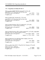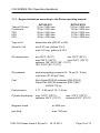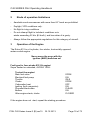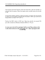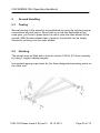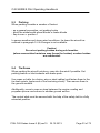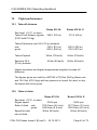
1
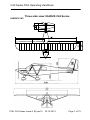
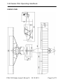
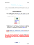
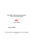
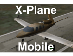
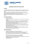
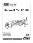
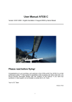
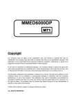
PILOT OPERATING HANDBOOK for the aircraft IKARUS C 42 Series Modell Nr. C42 / C42B / C42C LTZ-Nr. 61141 / 61141.1 / 61141.5 Type IKARUS C 42 Series Airplane Registration No. __________________________ Airplane Serial-No. __________________________ Reference: POH C42 Series Issue-2 (B) rev.10 This handbook is to be kept in the aircraft at all times. The described options of the C42 Series use are certified for Germany and have been tested in Germany. Please note that for using the C42 Series as a towplane for towing gliders, towing aerial signs or decanting sky divers, different regulations may apply in different countries. Please contact your local authorities for further clarification. POH C42 Series Issue-2 (B) rev10 30.10.2013 Page 1 of 72 RECORD OF MANUAL REVISIONS No. Issue No. 1 1 2 Description of Changes Date Signature POH C42 Series 30.08.2012 A.Kurz 1 Introduction 06.01.2013 A.Kurz 3 2 Instructions for the use of the LiFe-Battery 24.01.2013 A.Kurz 4 2 Page 55, 63, 71 Note Authorization 08.03.2013 A.Kurz 5 2 Page 55-67, 71-72, Appendices 7-11 removed 12.04.2013 L.Chan 6 2 Parachute Deployment, updated table of content. 12.04.2013 L.Chan 7 2 Removing Date in Reference line page 1 21.05.2013 L.Chan 8 2 C42B new diagram page 7 15.06.2013 L.Chan 9 2 Changing Reference line page 1 24.06.2013 L.Chan 9 2 TEMP Amendment Page 51 09.07.2013 L.Chan 10 2 Fixture of page 51 and removing TEMP section 30.10.2013 L.Chan 10 2 30.10.2013 L.Chan 10 2 30.10.2013 L.Chan Changing Reference Line and Issuing date Added a new page for recording (page 3) Total Pages 71 POH C42 Series Issue-2 (B) rev10 30.10.2013 Page 2 of 72 C42 Series Pilot Operating Handbook No. Issue No. Description of Changes Date Signature 10 2 Amended Weight and Balance Section Page 37 & 38 30.10.2013 L.Chan 10 2 Added a new Page (5) of the appendix, Parachute Mounting 30.10.2013 L.Chan 10 2 Total Pages 72, Amended Table of Content 30.10.2013 L.Chan POH C42 Series Issue-2 (B) rev10 30.10.2013 Page 3 of 72 C42 Series Pilot Operating Handbook Manufacturer & Representative Contact Information COMCO IKARUS GmbH Am Flugplatz 11 DKL Air Light Sarl B.P. 143 88367 Hohentengen / Swabia Germany L-8303 Capellen Luxembourg Tel: +49 7572 600 80 Fax: +49 7572 3309 Email: post@comco – ikarus.de Tel: +352 691 511 100 Fax: / Email: [email protected] Backup Certification Data Contact Information COMCO IKARUS GmbH DKL Air Light Sarl Am Flugplatz 11 B.P. 143 88367 Hohentengen / Swabia Germany L-8303 Capellen Luxembourg Tel: +49 7572 600 80 Fax: +49 7572 3309 Email: post@comco – ikarus.de Tel: +352 691 511 100 Fax: / Email: [email protected] Owner ______________________________ ______________________________ ______________________________ This Pilot Operating Handbook belongs to the aircraft:_________________ and is to be kept in the aircraft at all times. POH C42 Series Issue-2 (B) rev10 30.10.2013 Page 4 of 72 C42 Series Pilot Operating Handbook Introduction C42 series aircraft are built in compliance with the airworthiness requirements of various countries and are certified as Microlight, Ultralight, Advanced Ultralight and Light Sport Aircraft. To operate the aircraft the pilot must hold a license or certificate appropriate to this category of aircraft. The aircraft is not to be flown unless it is registered, carries registration markings in accordance with the requirements of the country in which the aircraft is to be flown, and has a Permit to Fly or certificate of Airworthiness valid in the country of operation. The aircraft is to be flown under daytime VFR conditions. Flight in conditions other than daytime VFR without the correct aircraft equipment and pilot ratings is extremely dangerous and can result in serious injury or death. Pilots holding licences for other categories, even higher ones, are required to be checked out by an appropriately qualified instructor prior to flying this aircraft as it possesses characteristics that are unique to light sport type aircraft. These characteristics include low inertia, susceptibility to turbulence and wind gradient and special engine considerations. The safety of all occupants, the aircraft and persons on the ground are the sole responsibility of the the Pilot in command. Do not operate this aircraft in a manner that would endanger the occupants, the aircraft or persons on the ground. POH C42 Series Issue-2 (B) rev10 30.10.2013 Page 5 of 72 C42 Series Pilot Operating Handbook Bear in mind that the engines used in C42 aircraft are not certified aviation engines and thus may not offer the same safety standards found in other classes of aircraft. Prepare your flight so that you can always reach an emergency landing area should you experience engine failure. On cross-country flights, ALWAYS keep an emergency landing field in sight. Changes to the control system, structure, wings and engine are prohibited. These changes would invalidate any certificate of airworthiness or permit to fly and as such would result in an insurance becoming null and void. All operating difficulties and equipment failures should be reported to your dealer or the manufacturer. For fire safety reasons, smoking is prohibited on board of the aircraft. POH C42 Series Issue-2 (B) rev10 30.10.2013 Page 6 of 72 C42 Series Pilot Operating Handbook Three side view: IKARUS C42 Series IKARUS C42 POH C42 Series Issue-2 (B) rev10 30.10.2013 Page 7 of 72 C42 Series Pilot Operating Handbook IKARUS C42B POH C42 Series Issue-2 (B) rev10 30.10.2013 Page 8 of 72 C42 Series Pilot Operating Handbook IKARUS C42C POH C42 Series Issue-2 (B) rev10 30.10.2013 Page 9 of 72 C42 SERIES Flight And Operators Manual Table of Contents Title page Record of Manual Revisions Manufacturer Contact Information Introductory remarks Three-side view Table of contents 1 2 4 5 7 10 1 Operating limitations ...................................................................... 13 1.1 1.2 1.3 1.4 1.5 1.6 1.7 1.8 1.9 1.10 1.11 Airspeeds: ..................................................................................... 13 Weights ......................................................................................... 13 Structural limitations: ..................................................................... 13 Center of gravity limits:.................................................................. 13 Airspeed markings: ....................................................................... 14 Engine rpm limitations ................................................................... 14 Rpm indicator markings ................................................................ 14 Flap settings .................................................................................. 14 Propellers for Rotax 912 UL: ......................................................... 15 Propellers for Rotax 912 UL S ..................................................... 17 Engine limitations according to the Rotax operating manual ....... 18 2 Kinds of operation limitations ........................................................ 19 3 Operation of the Engine .................................................................. 19 4 Flight Operations ............................................................................. 21 4.1 4.2 4.3 4.4 4.5 4.6 4.7 4.8 4.9 4.10 4.11 Taxiing:.......................................................................................... 21 Take-off and climb:........................................................................ 21 Cruising flight ................................................................................ 23 Turning flight ................................................................................. 23 Stalls ............................................................................................. 24 Descent and landing ..................................................................... 25 Shutting down the engine:............................................................. 25 Sudden loss of engine power: ....................................................... 26 Using the optional cowl flap on the aircraft C42 ............................ 28 Emergency procedures ................................................................ 29 Parachute Deployment ................................................................. 31 5 Ground Handling ............................................................................. 32 5.1 Towing........................................................................................... 32 POH C42 Series Issue-2 (B) rev10 30.10.2013 Page 10 of 72 C42 SERIES Flight And Operators Manual Table of Contents 5.2 Hoisting ......................................................................................... 32 5.3 Parking .......................................................................................... 33 5.4 Tie-Down ....................................................................................... 33 6 Minimum equipment ....................................................................... 35 7 Dimensions ...................................................................................... 35 8 Weight and balance ......................................................................... 36 8.1 Empty weight center of gravity: ..................................................... 37 9 Data placard and checklist: ............................................................ 39 10 “Before take-off” checklist ............................................................. 40 11 Approved equipment ...................................................................... 41 12 Flight performance: ......................................................................... 43 12.1 12.2 12.3 12.4 Take-off distance .......................................................................... 43 Rate of climb ................................................................................ 43 Cruising speed (solo) ................................................................... 44 Engine off performance (solo) ...................................................... 44 13 Attaching the wings ........................................................................ 45 13.1 Attaching the wings to the fuselage ............................................. 45 13.2 Folding the wings for hangaring ................................................... 47 14 Pre-flight inspection ........................................................................ 48 14.1 Engine .......................................................................................... 48 14.2 Landing gear ................................................................................ 48 14.3 Left wing ....................................................................................... 49 14.4 Left side of fuselage ..................................................................... 49 14.5 Empennage .................................................................................. 49 14.6 Right side of fuselage ................................................................... 50 14.7 Right wing .................................................................................... 50 14.8 Cabin, inside and outside ............................................................. 50 14.9 Instruments .................................................................................. 50 14.10 Drainage ....................................................................................... 50 15 Care and Maintenance .................................................................... 51 16 Rigging data ..................................................................................... 53 17 Special features of the aircraft equipped for handicapped pilots57 POH C42 Series Issue-2 (B) rev10 30.10.2013 Page 11 of 72 C42 SERIES Flight And Operators Manual Table of Contents 18 Flying with the IKARUS C42 Series with the removed doors ..... 59 19 Instructions for the use of the LiFe-Battery .................................. 60 20 COMCO IKARUS Manufacturer Warranty ..................................... 61 21 Appendix: ........................................................................................... 1 21.1 21.2 21.3 21.4 Placards ......................................................................................... 1 Data placard ................................................................................... 2 Service Problem Report Form -Aircraft .......................................... 3 Inspections performed .................................................................... 4 POH C42 Series Issue-2 (B) rev10 30.10.2013 Page 12 of 72 C42 SERIES Pilot Operating Handbook 1 1.1 Operating limitations Airspeeds: Never-exceed speed: C42 C42B / C42C VNE = 97 kts (180 km/h) VNE = 116 kts (216 km/h) Speed in turbulent air : Maximum manoeuver speed: Stall speed: flap position 1: flap position 2: flap position 3: VB VA VS1 VS2 VS3 = = = = = 97 kts (180 km/h) 80 kts (148 km/h) 40 kts (75 km/h) 38 kts (70 km/h) 35 kts (65 km/h) If VA speed is exceeded, only little rudder movement are allowed. 1.2 Weights Empty weight: cf. current weighing record Maximum take-off weight: 1041 lbs (472.5 kg) Maximum payload: see 8. Weight and balance Minimum payload: 144 lbs (65 kg) 1.3 Structural limitations: Positive limit load factor: Negative limit load factor: 1.4 Center of gravity limits: Reference datum: Forward center of gravity: Rearward center of gravity: POH C42 Series Issue-2 (B) rev10 +4 g -2 g Wing leading edge at a rib station 11.8 inches aft of datum (300 mm) 22.0 inches aft of datum (560 mm) 30.10.2013 Page 13 of 72 C42 SERIES Pilot Operating Handbook 1.5 Airspeed markings: White arc: Green arc: Yellow arc C42B / C42C: Yellow triangle: Yellow line: Red line: C42 C42B / C42C 38 - 57 kts 43 - 97 kts 97 – 116 kts VX = 51 kts VA = 75 kts (71 - 105 km/h) (79 - 180 km/h) (180 - 216 km/h) (95 km/h) (148 km/h) VNE = 97 kts VNE = 116 kts (180 km/h) (216 km/h) The deviation curve for the airspeed indicator can be interpolated from the following table IAS km/h EAS km/h 60 70 80 90 100 110 120 130 140 150 160 170 180 190 200 65 74 83 91 100 109 117 125 134 142 151 160 168 177 185 1.6 Engine rpm limitations Maximum engine rpm: Maximum continuous rpm: n = 5800 rpm, 5 min. max n = 5500 rpm 1.7 Rpm indicator markings Yellow arc: Red line: n = 5500 - 5800 rpm n = 5800 rpm 1.8 Flap settings Position 1: Position 2: Position 3: cruising take-off / landing landing POH C42 Series Issue-2 (B) rev10 30.10.2013 Page 14 of 72 C42 SERIES Pilot Operating Handbook 1.9 Propellers for Rotax 912 UL: With propeller WARP DRIVE 2-blade 68” (1.72 m Ø) constant speed, pitch 23.5° at 15.75 inches (0.40 m) from hub, full throttle rpm on the ground max. 5450 1/min Propeller rpm approx. n = 2400 1/min With propeller WARP DRIVE 3-blade 68” (1.72 m Ø) pitch 21.0° at 15.75 inches (0.40 m) from hub, full throttle rpm on the ground max. 5200 Propeller rpm approx. n = 2300 1/min 1/min With propeller Sport-Prop 3-blade 68” (1.72 m Ø) pitch 19.5° at 15.75 inches (0.40 m) from hub, full throttle rpm on the ground max. 4900 Propeller rpm approx. n = 2150 1/min 1/min With propeller GSC 3-blade 68” (1,72 m Ø) pitch 21.0° at 15.75 inches (0.40 m) from hub, full throttle rpm on the ground Propeller rpm 1/min 1/min POH C42 Series Issue-2 (B) rev10 30.10.2013 max. 4900 approx. n = 2150 Page 15 of 72 C42 SERIES Pilot Operating Handbook With propeller Neuform CR2-75 2-blade 69” (1,75 m Ø) pitch 27.0° at r = 14.37 inches (0.365 m), full throttle rpm on the ground max. 5100 Propeller rpm approx. n = 2250 1/min 1/min With propeller Neuform CR3-75 3-blade 69” (1,75 m Ø) pitch 24.0° at r = 14.37 inches (0.365 m), full throttle rpm on the ground max. 4800 Propeller rpm approx. n = 2100 1/min 1/min With propeller Kiev Prop BB 263/1700 3-blade (1,71 m Ø) Pitch 22,0° at r = 0,4 m from hub, full throttle rpm on the ground max. 4800 propeller rpm approx. n = 2100 1/min 1/min With propeller Helix H50F-1,75m-R-SI-12-3 3-blade (1,75 m Ø), Pitch. 16.0° at r = 656 mm full throttle rpm on the ground max. 4880 propeller rpm approx. n = 2150 1/min 1/min POH C42 Series Issue-2 (B) rev10 30.10.2013 Page 16 of 72 C42 SERIES Pilot Operating Handbook 1.10 Propellers for Rotax 912 UL S With propeller WARP DRIVE 3-blade 68” (1,72 m Ø) pitch 25.0° at 15.75 inches (0.40 m) from hub, full throttle rpm on the ground max. 5200 Propeller rpm approx. n =2150 1/min 1/min With propeller GSC 3-blade 68” (1,72 m Ø) pitch 25.0° at 15.75 inches (0.40 m) from hub, full throttle rpm on the ground max. 4900 Propeller rpm approx. n = 2000 1/min 1/min With propeller Neuform CR3-75 3-blade 69” (1,75 m Ø) pitch 27.0° at r = 14.37 inches (0.365 m), full throttle rpm on the ground max. 4800 Propeller rpm approx. n = 2000 1/min 1/min With propeller Neuform CR3-V-R2H 3-blade 69” (1,75 m Ø), adjustable pitch 16° - 30° at r = 29.53 inches (0.75 m), full throttle rpm on the ground max. 4200 - 5600 1/min Propeller rpm approx. n = 1700 - 2300 1/min With propeller Kiev Prop BB 283/1800 3-blade (1,80 m Ø) Pitch 24,0° at r = 0,4 m from hub, full throttle rpm on the ground max. 4850 Propeller rpm approx. n = 2000 1/min 1/min With propeller Helix H50F-1,75m-R-S-14-3 3-blade (1,75 m Ø), Pitch 17.0° bei r = 656 mm full throttle rpm on the ground ca. 4480 Propeller rpm ca. n = 1975 1/min 1/min POH C42 Series Issue-2 (B) rev10 30.10.2013 Page 17 of 72 C42 SERIES Pilot Operating Handbook 1.11 Engine limitations according to the Rotax operating manual Take-off (5 min) Continuous 75% 65% 55% ROTAX 912 81 hp / 5800 rpm 79 hp / 5500 rpm 59 hp / 5000 rpm 51 hp / 4800 rpm 43 hp / 4300 rpm ROTAX 912S 100 hp / 5800 rpm 95 hp / 5500 rpm 69 hp / 5000 rpm 61 hp / 4800 rpm 51 hp / 4300 rpm Type of oil automotive oils (API SF or SG) Amount of oil min 0.57 imp. gallons (2.6 l) max 0.67 imp. gallons (3.05 l) Oil temperature min 122°F (50°C) min 122°F (50°C) max 284°F (140°C) max 266°F (130°C) optimum 194°-230°F (90°-110°C) 194°-230°F (90°-110°C) Oil pressure: normal operating pressure 29 - 72 psi (2 - 5 bar) (cold start 101.45 psi/7 bar) Fuel: Euro-Super ROZ 95 unleaded (DIN 51603) Super Plus ROZ 98 unleaded (DIN 51607) AVGAS 100 LL Fuel pressure 2.17 - 5.80 psi (0.15 - 0.4 bar) Cylinder head temp. max. 302°F (150°C) optimum 230°F (110°C) max. 275°F (135°C) optimum 230°F (110°C) Magneto check at 4000 rpm rpm drop max. 300 rpm POH C42 Series Issue-2 (B) rev10 30.10.2013 Page 18 of 72 C42 SERIES Pilot Operating Handbook 2 Kinds of operation limitations - Aerobatics and manoeuvres with more than 60° bank are prohibited - Daylight, VFR conditions only. - No flight in icing conditions - Do not attempt flight in turbulent conditions or in winds exceeding 22 kts (40 km/h), and less when it is gusty. - Always follow the appropriate regulations for this category of aircraft. 3 Operation of the Engine The Rotax 912 is a 4-cylinder, four stroke, horizontally opposed, water-cooled engine. Never move the prop with the ignition (MAG) switches on! Fuel type for four-stroke 912 UL engine: Super leaded or unleaded, AVGAS 100LL To start the engine: Main fuel valve Electrical fuel pump Throttle Choke Carburettor heat Ignition (both magnetos) Propeller blade area Brakes After engine starts, choke OPEN ON IDLE OPEN OFF ON CLEAR ON CLOSED If the engine does not start, repeat the starting procedure. POH C42 Series Issue-2 (B) rev10 30.10.2013 Page 19 of 72 C42 SERIES Pilot Operating Handbook If the engine has been flooded, close main fuel valve, open the throttle to a half and start the engine. When the engine starts, quickly reduce the throttle to idle. A four-stroke engine requires a fairly long warm up period. Run the engine at 2000 rpm for at least 2 minutes then increase to 2500 rpm until the oil temperature is at least 122°F (50° C). Perform the MAG check at 4000 rpm. Rpm drop should not exceed 300 rpm with a maximum difference between MAGs of 115 rpm. In case your aircraft is equipped with a cowl flap, please refer to the instructions in the paragraph 4.9 : when equipped with a cowl flap POH C42 Series Issue-2 (B) rev10 30.10.2013 Page 20 of 72 C42 SERIES Pilot Operating Handbook 4 Flight Operations 4.1 Taxiing: The nose wheel steering is conventional and is directly connected to the rudder pedals. Push the right pedal to turn right. Push the left pedal to turn left. Taxiing is simple. The turning radius of the C-42 is small, and the plane handles cross wind during taxing very well. When taxiing with a strong tail wind, hold the control stick firmly in the neutral or nose-down position. When taking off or landing on bumpy grass strips, exercise caution to avoid striking the propeller. 4.2 Take-off and climb: After completing the "before take-off" checklist, make certain the runway and approach are free before you taxi to the takeoff position Set trim to neutral. (with an electrical trim the third lamp from above) Wing flaps in take-off position (flap position 2). Gently bring the throttle to full forward position, check tachometer. At full throttle, the tips of the propeller blades produce hard knocking sounds. Pull the stick slightly back during the initial roll. The nose wheel will lift off at approx. 27 kts (50 km/h). Further accelerate with the nose wheel up 2-4 inches (5-10cm) off the ground. . POH C42 Series Issue-2 (B) rev10 30.10.2013 Page 21 of 72 C42 SERIES Pilot Operating Handbook Aircraft with the Rotax 912 UL S (100 hp) have a greater engine torque which must be countered by a slight right rudder input. The aircraft will take-off at 38 kts (70km/h). Push the stick slightly forward and increase airspeed to 59 kts (110 km/h) in shallow climb. Continue to climb at 59 kts (110 km/h). Retract flaps at a height of approx. 150 ft. This will cause a slight noseheavy moment. After reaching a safe altitude the electrical fuel pump can be switched off. Trim the aircraft to 59 kts (110 km/h) and continue climbing. Slight right rudder is necessary to compensate both engine and propeller torque during climbing. Whenever possible, take-off into the wind. The maximum demonstrated crosswind component for take-off and landing is 16 kts (30 km/h). No special procedures are required. The classical “low-wing” procedure: keep windward wing low and carry out course corrections using the rudder. During the initial take-off phase, it is essential that the aircraft accelerate sufficiently in order to prevent stalling, should a sudden loss of power be experienced. By a loss of engine power at altitudes below 260 ft (80 m) do not attempt course corrections of more than 90°. Quickly trim the aircraft to a gliding speed of 54 kts (100 km/h) (push stick forward). Avoid obstructions. Using the flaps touch down at a low speed. The approach phase can be shortened by slipping. Before undertaking an emergency landing in rough terrain, turn off the fuel valve and the ignition. POH C42 Series Issue-2 (B) rev10 30.10.2013 Page 22 of 72 C42 SERIES Pilot Operating Handbook 4.3 Cruising flight In cruising flight the most economical cruise speeds are between 75 and 91 kts (140 - 170 km/h). The required engine performance depends upon aircraft load. Max. continuous engine speed is 5500 rpm. In order to fly the aircraft comfortably, it should be trimmed to the desired airspeed with the throttle set for the appropriate rpm for horizontal flight. Typical cruising flight: Engine speed Airspeed: Fuel flow: Rotax 912 UL 4500 rpm 81 kts (150 km/h) 2.20 - 2.64 gph (10 -12 l/h) The maximum speed of must never be exceeded. C42: C42B / C42C: Rotax 912 UL S 4500 rpm 86 kts (160 km/h) 2.42 - 2.86 gph (11 - 13 l/h) 97 kts (180 km/h) 116 kts (216 km/h In a turbulent weather the maximum airspeed is. At the first indication of carburettor icing (rpm drop, stuttering engine running, increase in fuel consumption as indicated by the flow meter, if installed) apply carburettor heat and, if possible, fly the aircraft into nonicing conditions. Turning flight Turns are coordinated using the aileron and rudders. With the increase of airspeed, significantly less amount of rudder deflection is needed. Banks of 45° degrees or more are not recommended, a banking angle of more than 60 degrees is prohibited. In steep banks keep the nose and airspeed under control by means of the rudders and elevator. 4.4 POH C42 Series Issue-2 (B) rev10 30.10.2013 Page 23 of 72 C42 SERIES Pilot Operating Handbook 4.5 Stalls In cruising flight configuration (flap position 1), the stalling speed is 39 kts (75 km/h). The engine cowling will be well above the horizon. At approximately 43 kts (80 km/h) there will be a slight buffeting of the airframe. When flown in this condition the aircraft is fully controllable. However, lateral altitude corrections must be done mainly with the rudder. Example: right wing low => rudder deflection to the left. If the aircraft is stalled slowly with the elevator in detent, it will enter into a stable stalled descent. Altitude loss can be up to 100 ft. During a whip stall, the aircraft clearly pitches down (up to 40°). By slightly releasing the elevator, airspeed will increase and the aircraft will return to horizontal flight. Maximum altitude loss is 250 ft. The aircraft reacts similarly in all flap positions. Stall speeds for the various flap position, take-off weight: 1042 lbs (472.5 kg): vs1 flap position 1 (cruising flight) vs2 flap position 2 (take-off/landing) vs0 flap position 3 (landing) ca. 40 kts (75 km/h) ca. 38 kts (70km/h) ca. 35 kts (65 km/h) The stall speeds above will be affected by variations in take-off weights. . POH C42 Series Issue-2 (B) rev10 30.10.2013 Page 24 of 72 C42 SERIES Pilot Operating Handbook 4.6 Descent and landing Begin with your approach early enough in order to set the correct landing configuration without hurrying. Activate carburettor heat. The electrical fuel pump must be switched on. In order to be able to steeply approach short landing strips, use flap position 3 (landing). Moreover, the glide path can be effectively shortened by a sideslip. Before proceeding to flap position 3 reduce the speed below velocity with flaps Vfe 57 kt (105 km/h), favourably are about 48 – 54 kts (90 - 100 km/h). On final approach with flap position 3 keep the speed at about 48 kts (90 km/h) with the engine at idle. The glide angle in flap position 2 (take-off/landing) is significantly more shallow and thus the flare distance is much longer. The initial velocity should be about 57 – 59 kt (105-110 km / h). At the height of approximately 10 ft (3m) begin rounding out to the landing flair. Begin final flair at the height of about 2 ft.(0.5 m). Landing speed is approx. 38 kts (70 km/h). 4.7 Shutting down the engine: Under normal conditions, the engine will have cooled down sufficiently during descent and taxiing so that it can be shut down by turning off the ignition. Shut off all electrical accessories and radios before shutting down the engine. POH C42 Series Issue-2 (B) rev10 30.10.2013 Page 25 of 72 C42 SERIES Pilot Operating Handbook 4.8 Sudden loss of engine power: I Loss of engine power during take off Depending upon speed and altitude, lower nose and trim to gliding speed (ca.54 kts / 100 km/h). Do not attempt to return to airfield if altitude is below 260 ft (80 m) after gliding speed has been reached. At lower altitudes it is best to land straight ahead without attempting any course corrections. Before attempting an emergency landing in rough terrain, turn off the fuel valve and switch off the ignition. When landing in a high vegetation (grain or similar) reduce speed directly above the vegetation by extending the flaps to position 3, pull stick fully aft and allow the aircraft to sink into the vegetation. II Loss of engine power during cruising flight Cross-country flights should be planned to ensure that a suitable landing field could be reached in the case of a loss of the engine power. Once gliding speed has been established (flap position 1 = cruising flight, VIAS = 48 - 54 kts / 90 - 100 km/h), look for a suitable landing field taking into consideration wind conditions. The best glide ratio is approx. 11:1 at 490 ft/min (2.5 m/s). A lower rate of descent can be achieved with flap position 2 (takeoff/landing), at approx. 48 kts (90 km/h), it does not however result in a better glide path. POH C42 Series Issue-2 (B) rev10 30.10.2013 Page 26 of 72 C42 SERIES Pilot Operating Handbook With sufficient altitude you may attempt to restart the engine, check: 1. Fuel valve 2 Magneto switches 3. Fuel 4. Fuel pump OPEN ON SUFFICIENT ON III Starting the engine in flight - both magneto switches - electrical fuel pump - throttle - carburettor heat - fire up engine using starter ON ON OPEN OFF Maintaining airspeed to windmill the prop can help. POH C42 Series Issue-2 (B) rev10 30.10.2013 Page 27 of 72 C42 SERIES Pilot Operating Handbook 4.9 Using the optional cowl flap on the aircraft C42 If your aircraft is equipped with the cowl flap, you have a possibility to control the temperatures of your engine via manual adjustment of the cooling air. Thereby, you are in the position to keep the engine temperatures in the optimal range (90°-110°) independent of outside temperatures. It works in C42/C52 both for the oil and cylinder head temperature due to the installed oil and water heat exchanger. Moreover, you can considerably shorten warm-up period by starting up the engine with a fully closed cowl flap. It does not only protect the engine but also saves fuel. Though, for a reasonable and secure handling of the cowl flap it is necessary to closely watch the oil and cylinder head temperature. Attention: If the cowl flap is closed the cooling air supply to the radiator will not be sufficient over a longer period, i.e. the oil and cylinder head temperature will rise to an inadmissible range (the red warning light range). In order not to forget to close the cowl flap, there will be installed an additional factory-provided warning light which flashes up when reaching the cylinder head temperature of 130° C. In this case, the cowl flap should be immediately fully opened. The cooling down oft the cylinder head temperature to admissive and optimal temperatures can be supported by reducing the engine output and increasing the airspeed in descending. The functionality test of the cowl flap is made during pre-flight inspection. Principally, you should not wait for flashing of the caution lamp, but you have to observe the temperature and to open the cowl flap manually at the temperature of 90°-110°. POH C42 Series Issue-2 (B) rev10 30.10.2013 Page 28 of 72 C42 SERIES Pilot Operating Handbook 4.10 Emergency procedures I Tipping due to lower speeds Reduce back pressure on the stick and lower the nose. Recover II Sideslip Set rudder in the opposite direction to a sideslip Reduce back pressure on stick III Spin Throttle to idle. Apply rudder opposite to the direction of rotation until the rotation will stop Reduce back pressure on stick Slowly pull aircraft up IV Spiral dive Set aileron and rudder opposite to the direction of rotation and pull back the stick slightly until a horizontal position will be taken. V Loss of elevator control With the elevator trim flap, the aircraft can be trimmed to speeds between 43 and 92 kts (80 und 170 km/h). In calm weather conditions it can also be used to try to land the aircraft. If in doubt, deploy the parachute rescue system. POH C42 Series Issue-2 (B) rev10 30.10.2013 Page 29 of 72 C42 SERIES Pilot Operating Handbook VI Loss of aileron control Use the rudder to control the aircraft via skidding rollingmoments. If in doubt, deploy parachute rescue system. VII Loss of rudder control Controlling flatter curves is possible with the ailerons only. If possible, perform a field landing in a straight flight. If in doubt, deploy parachute rescue system. VIII Carburettor fire Main fuel valve OFF Electrical fuel pump OFF Full throttle Sideslip Follow emergency landing procedures. POH C42 Series Issue-2 (B) rev10 30.10.2013 Page 30 of 72 C42 SERIES Pilot Operating Handbook 4.11 Parachute Deployment Attenttion: Follow the instructions in the BRS – parachute operator’s manual provided with your aircraft. (Comco Ikarus cannot be held responsible for any malfunctions of the parachute unless it is proven that the malfunction is caused by a faulty installation.) Every Aircraft equipped with a parachute is provided with adequate instruction manual depending of parachute manufacturer, and a registered functioning certificate. Be certain to follow the instructions of the manufacturer for required maintenance and particularly the avoidance of moisture in the parachute pack. Should the parachute get wet, it must be aired and repacked. (Only from an authorized reseller) The parachute is placed in the fuselage as described in the appendices of this manual. There is a time limit on the use of the rocket cartridge in rocket deployed systems. (Please follow the provided manufacturer instructions delivered with your aircraft) Removal, replacement or placement of a parachute should be undertaken by an authorized reseller or by the aircraft manufacturer to allow proper guarantee on the product and on the aircraft. Before taking off, remove the system safety pin. After landing secure the system with the safety pin. Should you need to make use of the rescue system, you should try to be in the frame of the parameters described in the parachute user manual: Emergency actions: You must first: Shut down the engine. Then pull the rescue clutch located between and above the 2 occupants. Try to steer the aircraft to a less agglomerated direction and ground. POH C42 Series Issue-2 (B) rev10 30.10.2013 Page 31 of 72 C42 SERIES Pilot Operating Handbook 5 Ground Handling 5.1 Towing Manual moving of the aircraft is accomplished by using the tail struts upper connections as push points. Since there is no tow bar applicable at the nose gear, you have to press down the tail to raise the nose wheel off the ground. With the nose wheel clear of ground, the aircraft can be simply steered by pivoting it on the main wheels. 5.2 Hoisting The aircraft may be lifted with a hoist of at least 1000 lb (0.5 tons) capacity by using T-support ceiling hangers. Use suitable spring snap hooks for the three designated mounting points on the cabin roof. POH C42 Series Issue-2 (B) rev10 30.10.2013 Page 32 of 72 C42 SERIES Pilot Operating Handbook 5.3 Parking When parking consider a number of factors: - as a general precaution, set parking brake - block the wheels with wheel blocks or brake blocks - flap to zero = position 1 In severe weather and strong wind conditions, tie down the aircraft as outlined in paragraph 5.4 if a hangar is not available. Caution: Do not set parking brakes during cold weather (when accumulated moisture may freeze the brakes) or when brakes are overheated. 5.4 Tie-Down When parking the aircraft outdoors, nose into the wind if possible. Set parking brakes or block wheels with brake pads. Use ropes or belts (no chains, wire or steel cables) and fasten them to the tie down points (upper end of the front wing struts). Then secure them to the ground anchors. Additionally, mount a rope or strap between the engine cowling and propeller spinner and secure to another ground anchor. The control stick must be secured with the help of the safety belt in a fully retracted position. POH C42 Series Issue-2 (B) rev10 30.10.2013 Page 33 of 72 C42 SERIES Pilot Operating Handbook Tie-Down Point at the Upper Front Strut Area Tie-Down Point between the Engine Cowling and Propeller Spinner POH C42 Series Issue-2 (B) rev10 30.10.2013 Page 34 of 72 C42 SERIES Pilot Operating Handbook 6 Minimum equipment - Four point harness for each seat - Airspeed indicator 0 - 116 kts (0 - 216 km/h). - Altimeter with Kolsmann window - Compass - Tachometer - Cooling liquid temperature gauge - Oil temperature gauge - Oil pressure gauge - Fuel gauge - Generator charge control - Data placard - - Pilot’s operating handbook - - Parachute rescue system - Checklist 7 Dimensions Cf. the following page 5 - 7. POH C42 Series Issue-2 (B) rev10 30.10.2013 Page 35 of 72 C42 SERIES Pilot Operating Handbook 8 Weight and balance Place the aircraft in a level position on three scales with the stabilizer and elevator leveled. The center of gravity is measured in mm or inches behind the reference datum and then calculated as a percentage of the wing chord. Reference datum (leading edge) wing chord l = 53.5 inches (1360 mm) determine measurements a and b (center of wheel axle). (I) xS mm = a − (II) xS % = G2 ⋅ b = ................mm G1 + G 2 xS mm ⋅100 = ...................% 1 1360 mm POH C42 Series Issue-2 (B) rev10 30.10.2013 Page 36 of 72 C42 SERIES Pilot Operating Handbook 8.1 Empty weight & Center of Gravity: Serial No.________________ Aircraft data sheet No:_______________ Type:________________ Weighting: Basic empty weight (standard equipment): ___________kg Operating empty weight (incl. optional equipment): ___________kg a= G1 mm, b = G1R : + G1L: mm = __________kg G2 = __________kg G total = __________kg xs mm: mm xs % : %L It is the pilot’s responsibility to ensure that the MTOW of 1041 lbs (472.5 kg) is not exceeded. Empty Weight: __________________________ kg Max. Useful Load: __________________________ kg Max. Useful Load at Full Tanks: __________________________ kg MTOW: 472,5 kg Place & Date:_____________________________________ Signature:________________________________________ POH C42 Series Issue-2 (B) rev10 30.10.2013 Page 37 of 72 C42 SERIES Pilot Operating Handbook Loading plan position kp empty weight 1. seats 2. fuel 3. baggage total weight weight x lever arm = torque cm cm kp kp 40 95 130 total torque kp center of gravity CG = total torque [cm kp] ------------------------------------------ = total weight [kp] allowed range for CG: empty weight CG: 300 - 560 mm behind zero datum (leading edge) 280 - 460 mm behind zero datum (leading edge) cm Place & Date:_____________________________________ Signature:________________________________________ Loading plan position kp empty weight 1. seats 2. fuel 3. baggage total weight weight x lever arm = torque cm cm kp kp 40 95 130 total torque kp center of gravity CG = total torque [cm kp] ------------------------------------------ = total weight [kp] allowed range for CG: empty weight CG: 300 - 560 mm behind zero datum (leading edge) 280 - 460 mm behind zero datum (leading edge) cm Place & Date:_____________________________________ Signature:________________________________________ POH C42 Series Issue-2 (B) rev10 30.10.2013 Page 38 of 72 C42 SERIES Pilot Operating Handbook 9 Data placard and checklist: Airspeeds Never-exceed speed C42 C42B / C42C 97 kts (180 km/h) 116 kts (216 km/h) Stall speed 35 kts (65 km/h) Load factor Positive limit load factor Negative limit load factor +4 g. -2 g. Maximum recommended wind speeds for operation Steady winds 22 kts (40 km/h) Demonstrated cross-wind component 16 kts (30 km/h) Capacity max min 65 kg The pilot operates this aircraft at his own risk. Manufacturer __________________________________________ Serial no. __________________________________________ Registration LTZ-Nr __________________________________________ Year of manufacture __________________________________________ Month __________________________________________ Aircraft basic empty weight __________________________________________ POH C42 Series Issue-2 (B) rev10 30.10.2013 Page 39 of 72 C42 SERIES Pilot Operating Handbook 10 “Before take-off” checklist 1. The seat belts are fastened? 2. Control system free and correct? 3. Parachute system unlocked? 4. Check fuel level 5. Electric fuel pump 6. Choke 7. Carburettor preheating (in C42B / C42C) 8. Electric instruments 9. Altimeter set? 10. Flaps (take-off/landing) 11. Check magnetos 12. Wind direction? 13. Runway and approach POH C42 Series Issue-2 (B) rev10 ON OPEN OFF ON flap position 2 CLEAR 30.10.2013 Page 40 of 72 C42 SERIES Pilot Operating Handbook 11 Approved equipment Engine: Rotax 912 UL C-gearbox, 2.27 to 1 reduction ratio Approved propellers -‐ -‐ -‐ -‐ -‐ -‐ -‐ -‐ Motor: WARP DRIVE 2-blade, 68” diameter WARP DRIVE 3-blade, 68” diameter Sport-Prop 170R 3-blade GSC 3-blade propeller, 68” diameter Neuform 2-blade CR2-75 ground adjustable propeller Neuform 3 blade CR3-75 ground adjustable propeller Kiev Prop 3-blade BB 263/1700 ground adjustable propeller Helix 3-blade H50F-1,75m-R-SI-12-3 ground adjustable propeller Rotax 912 UL S C-gearbox, 2.43 to 1 reduction ratio Approved propellers -‐ -‐ -‐ -‐ -‐ -‐ WARP DRIVE 3-blade, 68” diameter GSC 3-blade propeller, 68” diameter Neuform 3-blade CR3-75 ground-adjustable prop. Neuform 3-blade CR3-V-R2H in-flight-adjustable prop. Kiev Prop 3-blade BB 283/1800 ground-adjustable prop. Helix 3-blade H50F-1,75m-R-S-14-3 ground-adjustable prop POH C42 Series Issue-2 (B) rev10 30.10.2013 Page 41 of 72 C42 SERIES Pilot Operating Handbook Approved parachute rescue systems: -‐ -‐ -‐ -‐ -‐ BRS 5-UL4 BRS-6-1050-SP-DAeC Magnum 450 Speed (MTOW 450 kg only) Magnum High speed Soft pack Magnum Lightspeed Soft pack Be certain to follow the instructions of manufacturer for installation, required maintenance and particularly the avoidance of moisture in the parachute pack. Should the chute get wet, it must be aired and repacked. There is a time limit on the use of the rocket cartridge in rocket deployed systems. Before taking off, remove the system safety pin. After landing secure the system with the safety pin. Fuel tank capacity - approved versions: 1x / 2x / 3x / 4x 25l* 1x / 2x 11 imp gallons (50 l)* 1x / 2x 14.3 imp gallons (65 l) * no longer available Electrical flap drive POH C42 Series Issue-2 (B) rev10 30.10.2013 Page 42 of 72 C42 SERIES Pilot Operating Handbook 12 Flight performance: 12.1 Take-off distance Rotax 912 UL Rotax 912 UL S 345 ft (105 m) 310 ft (95 m) Take-off distance over 50 ft (15 m) obstacle solo 700 ft (210 m) gross 800 ft (245 m) 605 ft (185 m) 705 ft (215 m) Sea-level, +15°C, no wind Take-off roll distance (gross) (1041 lbs/472.5 kg) Take-off speed Speed at 50 ft (15 m) obstacle 38 kts (70 km/h) 49 kts (90 km/h) 38 kts (70 km/h) 49 kts (90 km/h) Higher elevations and higher temperatures lengthen the take-off distances. The figures given are valid for a MTOW of 793 lbs (360 kg) flown solo and 1041 lbs (472.5 kgs) with two persons on board. No wind, on dry, flat terrain with short grass. 12.2 Rate of climb Rotax 912 UL Sea-level, +15°C, no wind Engine speed 5500 rpm Rate of climb solo 1180 ft/min (6.0 m/s) gross 944 ft/min (4.8 m/s) Speed for best 49 kts (90 km/h) rate of climb POH C42 Series Issue-2 (B) rev10 30.10.2013 Rotax 912 UL S 5200 rpm 1377 ft/min (7,0 m/s) 1082 ft/min (5.5 m/s) 49 kts (90 km/h) Page 43 of 72 C42 SERIES Pilot Operating Handbook 12.3 Cruising speed (solo) C42 / at engine speed 4700 rpm (65%) 84 kts (155 km/h) 89 kts (165 km/h) C42B / at engine speed 4700 rpm (65%) 86 kts (160 km/h) 92 kts (170 km/h) C42C / at engine speed 4700 rpm (65%) 89 kts (165 km/h) 94 kts (175 km/h) Speed for a maximum range 76 kts (140 km/h) 78 kts (145 km/h) Maximum range with 11 imp. fuel gallons (50 l) tank capacity when windless approx. 270 nm (500 km) Maximum range with 14.3 imp. fuel gallons (65 l) tank capacity when windless approx. 350 nm (650 km) 12.4 Engine off performance (solo) MTOW 1041 lbs (472.5 kg) Minimum sink rate at 46 kts (85 km/h), flap position 2 393 ft/min (2 m/s) (take-off/landing) Best glide angle at 51 kts (95 km/h) flap position 1 1 to 11 (cruise) ATTENTION: Follow the instructions in the Rotax 912 operator’s manual. POH C42 Series Issue-2 (B) rev10 30.10.2013 Page 44 of 72 C42 SERIES Pilot Operating Handbook 13 Attaching the wings 13.1 Attaching the wings to the fuselage The wings are attached to the fuselage as follows: Step 1 Bring the wing main strut into a correct position to the wing by means of attaching the auxiliary struts in the receptacles on the front and rear wing spar. Step 2 Grip the main strut and raise the wing tip. Keeping the wing in a vertical position, carry the wing forward at 90° to the fuselage. Step 3 Turn the wing into a horizontal position, keeping the wing tip slightly higher than the wing root. Step 4 Slowly push the wing against fuselage and wing spar brackets. Step 5 Before pushing against the spar brackets, look for the slideway at the rear spar intake so that to lead the rear wing spar in the locking position. When the retaining bolt is touched, rotate the right wing slightly clockwise (the left wing must be rotated counter-clockwise). By moving slightly upwards, the rear wing spar will lock into the retaining bolt and the front wing spar will take position under the retaining bolt of the front wing tube holder. Push the front wing spar against the bracket while slightly lowering the wing tip. The front wing spar will lock into the retaining bolt. At the same time, launch the lower end of the wing support in the square cross-frame. Carefully check that both wing spars have properly locked into place. POH C42 Series Issue-2 (B) rev10 30.10.2013 Page 45 of 72 C42 SERIES Pilot Operating Handbook Step 6 Attention and now immediately 1 insert mounting bolts into the front wing spar bracket 2 insert mounting bolts into the rear wing spar bracket 3 insert toggle bolt into the square cross-frame spar to secure the wing support 4 all three bolts must be secured with the ring pins! 5 lift the wing and check that the wing support is fixed by the toggle bolt really reliable! Repeat Step 1 to 6 for the other wing. Remove any aileron locks used. Step 7 attach right and left aileron push rods to the see-saw connection. Carefully assure that the slide mechanism of the special ball-joint connectors is in completely closed position. Step 8 left and right flaps connection must be locked Step 9 fasten wing center section fairing POH C42 Series Issue-2 (B) rev10 30.10.2013 Page 46 of 72 C42 SERIES Pilot Operating Handbook 13.2 Folding the wings for hangaring (optional on Model C42 / C42B) 1. Remove wing center section fairing 2. Unlock aileron push rods from see-saw cross connection 3. Unlock left and right flaps connection 4. first: remove toggle bolts at the base of the wing support second: remove fastening bolts at the rear wing spar third: remove fastening bolts at the front wing spar The following 5 steps must be undertaken to fold back the wings. Step 1 Lift right wing at the wing tip, rotate slightly to unlock first the forward wing spar and then the rear one. Step 2 Draw the wing back off the fuselage until the stop ring on the slide tube is reached. Step 3 Turn the wing into a vertical position – bottom surface of the wing to the forward. Step 4 Swing the wing tip back. Step 5 Place the wing tip on to the retainer bracket on the empennage. Repeat steps 1 to 5 for the left wing. POH C42 Series Issue-2 (B) rev10 30.10.2013 Page 47 of 72 C42 SERIES Pilot Operating Handbook 14 Pre-flight inspection Before each flight the pilot must carry out a visual inspection of the aircraft. 14.1 Engine - Check propeller and spinner for damage and security - Check cowling near the propeller for abrasion (sign of defective engine suspension or improper cowling attachment) - Check for leakage under the engine cowling - Check cooling liquids and lubricants - Check secure attachment of the engine cowling - Check that coolers are clean (oil cooler, water cooler) - Check air vents for blockage - Check NACA-intake for blockages 14.2 Landing gear - Check secure attachment of all components (hub caps, brake cylinders, brake discs) - Check for a visible deformation - Check air pressure in the gas-filled shock absorber (aircraft level, pull aircraft down and release, gas-filled shock absorber must fully rebound) - Check pressure and condition of tires POH C42 Series Issue-2 (B) rev10 30.10.2013 Page 48 of 72 C42 SERIES Pilot Operating Handbook 14.3 Left wing - Wing spar connections secured? - Wing struts properly attached and secured? - Auxiliary struts secured with quick-release fasteners? - Pitot tube secured and free from dirt and water? - Check aileron shift levers and push rods by opening the zippers on the wing bottom - Check condition of fabric covering (rips, etc.) - Check profiled struts for secure attachment - Check wing tips and wing tube for deformation - Check attachment of ailerons and flaps. - Check QR-Spades of the C42C model for secure attachment and deformation. 14.4 Left side of fuselage - Check condition of glass-fiber fairing (cracks, holes, etc.) - Check secure attachment of glass-fiber fairing (check for missing screws at the upper/lower connection) - Check elevator shift lever through the baggage hatch in the fuselage wall - Tank filler cap secured? 14.5 Empennage - Check attachment of the horizontal stabilizer - Check control surface hinges? - Check elevator inter-connection - Trim flap secured? - Check attachment and connection of the Flettner rudder of the C42C model - Check connections of the elevator push rod - Check the elevator struts for a secured attachment and possible deformation - Check rudder cables for being connected and secured - Check fabric covering (rips, chafing) POH C42 Series Issue-2 (B) rev10 30.10.2013 Page 49 of 72 C42 SERIES Pilot Operating Handbook 14.6 Right side of fuselage - Check condition of glass-fiber fairing (cracks, holes, etc.) - Check secure attachment of glass-fiber fairing (missing screws, etc.) 14.7 Right wing - cf. left wing 14.8 Cabin, inside and outside - Check condition of windscreen, doors including locking mechanism (cracks) - Check free movement of the steering (control stick, pedals, flap lever with a lock) - Check the brake lever and stand lock - Check aileron lever for being connected and secured - Visually check aileron cables and pulleys - Check fuel valve 14.9 Instruments - Power supply (ignition switch in the position 1) - Altimeter setting - Amount of fuel - Functioning of the radio and intercom system 14.10 Drainage - Drainage of the fuel tanks (the drainage tap is located under the copilots seat) POH C42 Series Issue-2 (B) rev10 30.10.2013 Page 50 of 72 C42 SERIES Pilot Operating Handbook 15 Care and Maintenance 1. Care and cleaning All metal parts are corrosion-resistant and require no special care. Dirt on the aircraft and the fabric can be removed by using clear water. Repair of the wing fabric: repair even the smallest rips for your personal safety. A wing fabric repair kit is available from the manufacturer. It is to be applied to a clean, grease-free area by means of contact adhesive. Larger rips in the fabric or along the seams in any case must be repaired by the covering specialists. When in doubt, contact the manufacturer. Be especially careful in the maintenance and cleaning of the cabin glazing! It is highly recommended to abundantly use clear water with a little detergent for softening and rinsing of contamination. For drying, a fine microfiber cloth should be used which is solely used for this purpose. By no means solvent-based or acid-based detergents may be used. 2. All maintenance All maintenance work must be carried out by appropriately qualified persons. 3. Especially Repair works and major changes must be reported and officially inspected. 4. Airworthiness inspections in Germany must be carried out by the manufacturer or by DAeC inspectors. In other countries different regulations may apply. POH C42 Series Issue-2 (B) rev10 30.10.2013 Page 51 of 72 C42 SERIES Pilot Operating Handbook 5. Repair works Repairs by the owner are limited to the exchange of defective parts. Only original spare parts may be used. In no case shall any part be reprocessed, straightened or otherwise processed for repair and re-installation. 6. Periodical inspections Periodical inspections (50 / 100 hour inspection) should be carried out in accordance with the provisions of the C42 COMCO IKARUS GmbH Maintenance Manual and 912 ROTAX Maintenance Manual. If not conducted, the safety of the aircraft is not guaranteed and warranty claims may be omitted. The periodical inspections should be conducted in one of our IFC (Ikarus Flight Center), ITB (Ikarus Technical Base), ISC (Ikarus Service Center).If periodical inspections should be conducted by the owner himself, these technical documents (Maintenance Manual) have to be ordered at IFC/ITB/ISC or directly at COMCO IKARUS GmbH. 7. Technical problems Technical problems or defects should be reported to - the manufacturer - the relevant national authority POH C42 Series Issue-2 (B) rev10 30.10.2013 Page 52 of 72 C42 SERIES Pilot Operating Handbook 16 Rigging data Wingspan C42 / C42 B: Wing area 31,0 ft 134,5 ft2 (9450 mm) (12,5 m2) Wingspan C42 C: Wing area 28,6 ft 128,1 ft2 (8710 mm) (11,9 m2) Wing chord at root: Wing dihedral 1° 4,7 ft (1435 mm) a.) Incidence angle of the wing relative to the fuselage main tube: Note 8,5° The incidence angle is measured from the lower edge of the rear wing tube to the lower edge of the front wing tube at the root rib. b.) Incidence angle of the horizontal stabilizer relative to the fuselage main tube: 7° Note The stabiliser incidence angle is measured from the lower edge of the front tube to the lower edge of the rear tube of the horizontal stabiliser. Incidence angle difference of the wing to the horizontal stabiliser Measured at the root rib: 1,5° POH C42 Series Issue-2 (B) rev10 30.10.2013 Page 53 of 72 C42 SERIES Pilot Operating Handbook c.) Control surface deflections Note: The angle of the aileron bottom relative to the wing chord is -5° (tangent front to rear spar). It is defined by the length of the aileron push rods. -5° Distance from axis of rotation Aileron Neutral p. -7°±-1° -1.38” ± 0.39” (-35 mm ± 10 mm) Up 20°±-2° 3.54” ± 0.39” (90 mm ± 10 mm) Down 14°±-2° 2.76” ± 0.39” (70 mm ± 10 mm) Measuring point distance from the steering axis: 9.84” (250 mm) Spade settings on the aileron in the C42C model Spade angle in relation to the QR-bottom +3° ± 1° Measurement with water level at base of 1 cm under Aileron end strip POH C42 Series Issue-2 (B) rev10 30.10.2013 Page 54 of 72 C42 SERIES Pilot Operating Handbook Rudder Left 32°±-2° 8.86” ± 0.39” (210 mm ± 10 mm) Right 32°±-2° 8.86 ” ± 0.39” (210 mm ± 10 mm) Measuring point distance from the steering axis: 16.24” (410 mm) Elevator Up 28°±-2° 8.27” ± 0.59” (210 mm ± 15 mm) down 20°±-2° 5.12” ± 0.59” (130 mm ± 15 mm) Measuring point distance from the steering axis: 16.24” (410 mm) Flettner rudder When the elevator neutral: Flettner rudder 0° ± 2° 78 mm ± 3 mm Flaps Note: Flap angle is measured from the flap bottom to the bottom of the wing at the root area (tangent front to rear spar) Position 1 (cruise) Position 2 -5°±-1° 1.06” ± 0.39” (27 mm ± 10 mm) +11°±-1° 2.36” ± 0.39” (60 mm ± 10 mm) +32°±-1° 6.69” ± 0.39” (170 mm ±10 mm) (take-off/landing) Position 3 (landing) Measuring point distance from the steering axis: 12.20” (310 mm) Trim flap Lever nose-down: trim flap in relation to the rudder area -5° Note: with mechanically actuated trim flaps do not exceed -5° upwards -5° POH C42 Series Issue-2 (B) rev10 30.10.2013 Page 55 of 72 C42 SERIES Pilot Operating Handbook d) Landing gear Main landing gear 2.0 - 2.5 bar 29 - 36 psi Nose landing gear 1.6 - 2.0 bar 23 - 29 psi Shock absorbers Amount of oil Hydraulic oil 28.0 - 34.0 bar 0.42 pts (200 ml) HVP 10 400 - 490 psi e) Brakes In the Ikarus C42 series different brake systems are used. e.g.-Sachs, Magura, Tost and Beringer brakes. For service information, please see our maintenance manual or ask one of our IFC and ISC. Always use low viscosity mineral oil or “CASTROL LHM 1756” ”PENTOSIN LHM” (Citroen) Never use Glykol-based brake fluid!! f) Engine Tightening torque for propeller attachment screws Tightening torque for propeller blade setting screws 25 Nm 12 - 15 Nm For service information, please see our maintenance manual or ask one of our IFC and ISC. POH C42 Series Issue-2 (B) rev10 30.10.2013 Page 56 of 72 C42 SERIES Pilot Operating Handbook 17 Special features of the aircraft equipped for handicapped pilots 1. Equipment If the following additional equipment is installed in the aircraft, it can be operated without using the feet to control the nose wheel and the rudder: 1. modified throttle shaft including throttle lever extension; 2. rudder control lever with push rod; 3. placard on the rudder control lever. Installation must be undertaken in accordance with the instructions of the manufacturer. The unauthorised alteration of the equipment for handicapped pilots is not permitted. 2. Installation / Dismantling The rudder control lever is installed by attaching to the mounted axle in the main tube and bolting with a hexagonal bolt M8xM40. The push rod which is attached to the rudder control lever is connected to the right pedal of the left seat by a quick-release fastener. The sliding sleeve of the quick-release fastener is then checked for a proper fit in the locked position. Throttle lever length is then set so that the knob of the throttle lever is approximately ten to thirty millimetres under the rudder control lever and can pass freely under it. The additional control equipment is dismatled in reversed order. POH C42 Series Issue-2 (B) rev10 30.10.2013 Page 57 of 72 C42 SERIES Pilot Operating Handbook 3. Operation The nose wheel and the rudder are controlled with the left hand on the rudder control lever. By pulling out the rudder control lever, the aircraft turns to the left, by pushing it in, the aircraft turns to the right. The right hand remains constantly on the control stick and operates the elevator, aileron and brakes. The left hand operates the rudder control lever and the throttle lever, which is located directly below the rudder control lever. Take-off: 1. Align the aircraft on the runway, left hand (LH) on the rudder control lever. 2. Apply throttle expeditiously with LH. 3. Put LH immediately back to the rudder control lever and steer aircraft during take-off run. 4. After take-off in approximately 5 to 10 m above the runway, use LH to check that the throttle lever is still in the full throttle position. 5. Excepting in case of power changes, LH remains constantly on the rudder control lever. The various flight conditions, e.g. horizontal flight, turn, slow flight, sideslip, are not affected. Landing: The landing approach is by default. In the case of crosswind, the wingdown method should be used. Attention should be paid to the following when flaring out: 1. Air speed is approx. 100 km/h until flare out is in approx. 4 to 5 m above the runway, LH - on the rudder control lever. 2. Throttle to idle using LH. 3. LH should be immediately back to the rudder control lever and steer aircraft during landing roll. When carrying out touch-and-go, follow the procedures for take-off. POH C42 Series Issue-2 (B) rev10 30.10.2013 Page 58 of 72 C42 SERIES Pilot Operating Handbook 18 Flying with the IKARUS C42 Series with the removed doors Under the following conditions, the IKARUS C42 SERIES may be flown with the dismantled doors: • All loose items (maps, documents) should be properly secured. • The dropping of objects during flight is prohibited. • Maximum speed for flights with one or both doors removed is 150 km/h IAS. • Side-slipping is not permitted with dismantled doors. • Turbulence in the cockpit will increase when the flaps are set to position III. POH C42 Series Issue-2 (B) rev10 30.10.2013 Page 59 of 72 C42 SERIES Pilot Operating Handbook 19 Instructions for the use of the LiFe-Battery The usage of LiFe-Batteries on C42/C52 is related to the battery modulation technology which allows for an effective reduction of the empty weight for more than 3,5 kg due to its high energy density. These batteries are characterised by the following qualities: - low-maintenance - small size - high voltage - fast charging - high impulse current ability - extremely low self-discharge What is special is the ability to produce high battery power during the starting procedure, though the battery develops it only at a certain minimum temperature. At cold outside temperatures it can lead to the false conclusion that the battery is empty. Therefore, we recommend before the very starting procedure to preheat the battery by spinning of the starter (2-3 times for 2-3 sec.) without switched on magnetos. Once the engine is rotating with a sufficient rpm, the starting procedure can be accomplished as usually. (switching on the fuel pump, magnetos and choke) . POH C42 Series Issue-2 (B) rev10 30.10.2013 Page 60 of 72 C42 SERIES Pilot Operating Handbook 20 COMCO IKARUS Manufacturer Warranty Warranty Information Comco Ikarus guarantees to you, the original purchaser, that the aircraft, which you have purchased from an authorised Ikarus Flight Center, to be in conformance with the applicable Comco Ikarus specifications current at the time of manufacture for a term of two (2) years from the date of purchase of the aircraft. (Warranty Term) This is the complete and exclusive warranty for the aircraft with original accessories of the Comco Ikarus GmbH. In no event shall Comco Ikarus be liable for damages or losses in excess of the purchase price nor for any incidental special or consequential damages, including without limitation loss of use, loss of time, inconvenience, commercial loss, lost profits or savings arising out of the use or inability to use the aircraft, to the full extent such may be disclaimed by law. This warranty does not affect any statutory rights that you are entitled to from your purchase agreement, such as warranty of fitness for an ordinary use and service, which is common for things of the same kind, so the claims against the seller of the aircraft under the purchase agreement. Warranty Service Should the aircraft not comply with the warranted specifications, the warranty claim consists of a repair of the defect by Comco Ikarus at no charge. Thus, you are bound to inform Comco Ikarus of the lack of conformity to the applicable specifications of the aircraft promptly if you detect a defect in material, workmanship or lack of conformity, in any case before the expiry of the warranty period, you must immediately bring your aircraft for service to the authorised Ikarus Flight Center, Ikarus Technical Basis or a Ikarus Service Center. POH C42 Series Issue-2 (B) rev10 30.10.2013 Page 61 of 72 C42 SERIES Pilot Operating Handbook Comco Ikarus shall not be bound by product related statements not directly made by Comco Ikarus nor any warranty obligations applicable to the seller. In most cases the authorized Ikarus Flight Center which sold and/or installed your aircraft and original accessories will honour a warranty claim and/or provide warranty service. Claiming In order to claim the warranty service you must return the aircraft and/or accessory in question to the authorised Ikarus Flight Center or Ikarus Service Center in the original configuration as supplied by Comco Ikarus. The microlight aircraft should be accompanied with the following information - Name of the owner Address of the owner Telephone numer of the owners Email address of the owner Comco Ikarus serial number Total flying hours Number of landings Description oft the problem Digital photos if requested In order to be eligible to receive warranty service, you must present your receipt of purchase or a comparable substitute proof of purchase bearing the date of purchase. You must ensure that all repair or customer service is handled at all times by the authorized Ikarus Flight Center or Ikarus Service Center in accordance with Comco Ikarus service requirements. In some cases, you may be requested to provide additional information concerning the maintenance of the aircraft by the authorized Ikarus Flight Centers or Ikarus Service Centers only, therefore it is important to keep a record of any previous repairs, and make them available if questions arise concerning maintenance. POH C42 Series Issue-2 (B) rev10 30.10.2013 Page 62 of 72 C42 SERIES Pilot Operating Handbook Requirements for a warranty This warranty will not apply if the type or serial number on the aircraft has been altered, deleted, duplicated, removed or made illegible. Comco Ikarus reserves the right to refuse from free-of-charge warranty service if the requested documentation cannot be presented or if the information is incomplete, illegible or incompatible with the factory records. Repair, at Comco Ikarus option, may include the replacement of parts or accessories with functionally equivalent, reconditioned or new parts. Replaced parts or accessories are warranted for the balance of the original warranty time period. The original warranty period will not be extended. All original parts that have been replaced shall become the property of Comco Ikarus. Comco Ikarus does not warrant the installation, maintenance and service of the products, parts and accessories. Comco Ikarus will not be responsible in any way for problems or damages caused by not distributed by Comco Ikarus accessories which are connected to the aircraft or used together with it. Neither does Comco Ikarus guarantee trouble-free operation of the Comco Ikarus aircraft in conjunction with these accessories. Such accessories are specifically excluded from this guarantee. As long as the aircraft is used in conjunction with the accessories not supplied by Comco Ikarus, Comco Ikarus does not warrant the operation of the product combination and Comco Ikarus will not honour any warranty claim where the aircraft is used in such a combination and it is determined by Comco Ikarus that there is no fault with the aircraft. Comco Ikarus specifically disclaims any responsibility for any damage to the aircraft and for other damages of the aircraft with the accessories, when such accessories are not manufactured or distributed by Comco Ikarus. POH C42 Series Issue-2 (B) rev10 30.10.2013 Page 63 of 72 C42 SERIES Pilot Operating Handbook What is not covered by the warranty This warranty is not valid if the defects are due to damage, misuse, tampering, neglect or lack of care and in case of alterations or repair carried out by unauthorized persons. The following are examples of defects or damage not covered by this product warranty 1. Defects or damage resulting from use of the aircraft in other than is normal and customary manner. 2. Defects or damage resulting from misuse, use with incompatible devices or accessories, accident or neglect. 3. Defects or damage due to improper operation, testing, maintenance, installation, adjustment, unauthorized modifications. 4. The aircrafts which are disassembled or repaired other than by Comco Ikarus or the IFC / ISC in such a manner as to adversely affect performance or prevent adequate inspection and testing to verify any warranty claim. 5. All plastic and synthetic surfaces and all other externally exposed parts that are scratched or damaged due to a customer’s normal use. 6. Periodic maintenance and repair or replacement of parts due to a normal wear and tear. POH C42 Series Issue-2 (B) rev10 30.10.2013 Page 64 of 72 C42 SERIES Pilot Operating Handbook 21 Appendix Appendix: 21.1 Placards Subject Location Aerobatics warning Instrument panel Trim Roof frame Flaps, mechanical Roof frame Engine oil specifications Oil control cap Fuel specifications Filler neck Baggage loading Baggage compartment opening Deviation table Instrument panel Controls Center console - Choke - Heating - Carburettor heat Fuel valve Center console Data placard Center console Type placard, fire-resistant Fuselage tube, behind the tank POH C42 Series Issue-2 (B) rev.10 30.10.2013 Page 1 of 72 C42 SERIES Pilot Operating Handbook Appendix 21.2 Data placard Type: ______________ Manufacturer: COMCO IKARUS GmbH D-88367 Hohentengen Germany Serial No.: _________________ Year of production: _________________ Never-exceed speed C42 C42B / C42C Stall speed 97 kts (180 km/h) 116 kts (216 km/h) 35 kts (65 km/h) Structural limitations positive limit load factor: negative limit load factor: 4g 2g Load limits: Maximum take-off weight: Minimum useful load 1041 lbs (472.5 kg) 143 lbs (65 kg) Useful load according to the Pilot Operating Handbook POH C42 Series Issue-2 (B) rev.10 30.10.2013 Page 2 of 72 C42 SERIES Pilot Operating Handbook Appendix 21.3 Service Problem Report Form -Aircraft Aircraft Type: ______________ Year of Manufacture: ______________ Serial No._______________ Engine Type_____________ Manufacture______________________________________________ Owner:__________________________________________________ Airframe:_________________________________________________ Total Flight Hours until Defect: __________________________________ Engine:_________________________________________ Airframe:_________________________________________ Total Flight Hours (Pilot) on Aircraft: _______________________________ Description of damage:_________________________________________ ____________________________________________________________ ____________________________________________________________ Damage Report: ______________________________________________ Name:__________________________ Date:______________________ Signature:__________________ POH C42 Series Issue-2 (B) rev.10 30.10.2013 Page 3 of 72 C42 SERIES Pilot Operating Handbook Appendix 21.4 Inspections performed Type: ____________ Serial No._________________ Marking:________________________ Date Type of inspection Recognised expert POH C42 Series Issue-2 (B) rev.10 30.10.2013 Page 4 of 72 C42 SERIES Pilot Operating Handbook Appendix Mounting Position of the Parachute Rescue System Please Note: In order to avoid the parachute pack gliding down, it is necessarily to use a cable tie (450 x 7.8 mm) to lock the position. The cable tie has to go around the rocket mount and through the first fixing point of the pack. Make sure it is tied up firm. POH C42 Series Issue-2 (B) rev.10 30.10.2013 Page 5 of 72 C42 SERIES Pilot Operating Handbook Appendix Location of the parachute rescue system POH C42 Series Issue-2 (B) rev.10 30.10.2013 Page 6 of 72 C42 SERIES Pilot Operating Handbook POH C42 Series Issue-2 (B) rev.10 30.10.2013 Appendix Page 7 of 72 C42 SERIES Pilot Operating Handbook POH C42 Series Issue-2 (B) rev.10 30.10.2013 Appendix Page 8 of 72