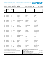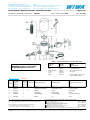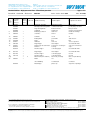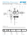
1
WIWA GmbH & Co. KG Gewerbestr. 1 – 3 • 35633 Lahnau, Germany Tel. +49 (0) 64 41-6 09-0 • Fax +49 (0) 64 41-6 09-50 E-mail: [email protected] • Internet: www.wiwa.de WIWA LP 1244A Exec. Blvd., Suite #101 • Chesapeake, VA 23320, USA Tel. +1.866.661.2139 • Fax +1.757.436.2103 E-mail: [email protected] • Internet: www.wiwa.com User's Handbook: WIWA Airless ❍ Herkules 35061 ❍ Herkules 35075 ❍ Herkules 48046 ❍ Herkules 48057 ❍ Herkules 60028 ❍ Herkules 60036 …………………………… User's Handbook WIWA Airless AA014•e•08.03 1 © Copyright 2002 WIWA Wilhelm Wagner GmbH & Co. KG WIWA GmbH & Co. KG Gewerbestr. 1 – 3 • 35633 Lahnau, Germany Tel. +49 (0) 64 41-6 09-0 • Fax +49 (0) 64 41-6 09-50 E-mail: [email protected] • Internet: www.wiwa.de WIWA LP 1244A Exec. Blvd., Suite #101 • Chesapeake, VA 23320, USA Tel. +1.866.661.2139 • Fax +1.757.436.2103 E-mail: [email protected] • Internet: www.wiwa.com Declaration of Conformity We, WIWA Wilhelm Wagner GmbH & Co. KG Gewerbestraße 1 – 3 D-35633 Lahnau hereby declare in sole responsibility that the product Airless Farbspritzgerät, machine types: Herkules 35061; 35075; 48046; 48057; 60028; 60036 to which this declaration relates complies with the following standards and documents, in accordance with the EC Machinery Directive 98/ 37 EC: in accordance with the EC Guideline 94/9/EG, Appendix VIII: • DIN EN 292 Part 1, edition 11.91 (German version EN 292-1 : 1991) • • DIN EN 292 Part 2, edition 06.95 (German version EN 292-2 : 1991 + A1 : 1995 DIN EN 1127-1 edition 1997-10 (German version EN 1127-1;1997) • • DIN EN 1050, edition 01.97 (German version EN 1050 : 1996) DIN EN 13463-1 edition 2001-01 (German version EN 13463-1;2001) • DIN EN 983, edition 09.96 (German version EN 983 : 1996) • Third Ordinance of the Equipment Safety Act (January 18, 1991) The following standard was used for noise measurements: • The required documentation is on file at: TÜV Anlagentechnik GmbH, EU-Code 0035 The equipment listed is classified in Group II, Category 2G. DIN EN ISO 3744, edition 11.95 (German version EN ISO 3744 : 1995) Lahnau, 01.07.2003 Place, date 2 © Copyright 2002 WIWA Wilhelm Wagner GmbH & Co. KG Heidrun Wagner-Turczak Managing Director User's Handbook WIWA Airless AA014•e•08.03 WIWA • Gewerbestr. 1 – 3 • 35633 Lahnau, Germany Tel. +49 (0) 64 41-6 09-0 • Fax +49 (0) 64 41-6 09-50 E-mail: [email protected] • Internet: www.wiwa.de Safety Information First read, then start 0 0.1 Remember that Airless Paint Spraying Equipment works under extreme pressure and that high levels of spraying pressure are created! ■ Never hold your finger or hand in front of the gun and never reach into the spray. ■ Never point the spray gun towards yourself, other people or other living creatures. ■ Always pay close attention to the references and specifications found in the user's handbook! Before each usage, be especially certain to: ■ Check the grounding conditions (for the unit and the object to be sprayed). ■ Check the seal of all connecting and mounted parts. ■ Observe the maximal allowed pressure of the unit and accessory parts. Beforebeginning any work on the equipment and at any pause during operation, be absolutely required to: ■ Turn off the spraying equipment at the air pressure stop valve. ■ Release the pressure found in the spraying gun and hose. ■ Secure the spraying gun. Pay attention to safety! The accident prevention regulation "Handling of Coating Materials" (VBG 23) and the guidelines covering fluid sprayers ZH1/406 from the German Employer's Liability Insurance Association are to be observed without fail. To ensure a safe operating environment, the condition of fluid sprayers must be inspected by an expert every 12 months or sooner, if deemed necessary. A written record of the inspection results is to be kept. Remaining paint and solvent are to be disposed of according to legal regulations. This also applies for environmently friendly water lacquer or enamel systems. In case of injuries, consult a physician or go to the next hospital without delay. If paint/material or solvent has gone into the skin, the physician has to be informed about the type of paint/material or the solvent applied.Therefore, always ensure that the product specification sheet, with address and telephone number of the manufacturer, is at your disposal! User's Handbook WIWA Airless AA000•e•06.02 3 © Copyright 2001 WIWA Wilhelm Wagner GmbH & Co. KG WIWA • Gewerbestr. 1 – 3 • 35633 Lahnau, Germany Tel. +49 (0) 64 41-6 09-0 • Fax +49 (0) 64 41-6 09-50 E-mail: [email protected] • Internet: www.wiwa.de Contents Preface 1 1.1 This User’s Handbook must always be available to operating staff The operating authority of the equipment must ensure, that a user`s handbook is available to the operator, in a language which he understands. Dear customer! Thank you for your decision to purchase WIWA equipment. In the user’s handbook, you can find all information required for the proper handling of your WIWA Airless Paint Spraying Machine. However, for safe operation, there are further essential details which you should adhere to: Please read and observe the guidlines valid for your country. In Germany, the "Richtlinien für Flüssigkeitsstrahler" (Guidelines for fluid sprayers) published by: Hauptverband der Gewerblichen Berufsgenossenschaften (Industrial Employer's Liability Insurance Association), are valid. Manufacturer’s notes and operating guidelines for coating and pumping materials should be observed at all times. No method of operation should be exercised which impairs the safety of WIWA products and the operating personnel. We wish you much success and excellent working results when appliying your WIWA Airless Paint Spraying Machine. WIWA Wilhelm Wagner GmbH ^ Co. KG Copyright The copyright for this user’s handbook remains with WIWA Wilhelm Wagner GmbH & Co. KG. The user’s handbook is intended for preparation, operating and maintenance staff. It contains technical regulations and drawings which may not, in whole or in part, be copied, distributed or be used by or passed on as information to others for whatever purposes without authorisation. WIWA Wilhelm Wagner GmbH & Co. KG Gewerbestra-e 1/3 • 35633 Lahnau Tel.: 06441/609/0 • Fax.: 06441/6095/0 This user’s handbook is only valid in conjunction with the machine card which is presented in chapter 9.3 of the user’s handbook for the equipment you have purchased. Please ensure that the data on the type plate corresponds with the information on the machine card. If they do not correspond or the user’s handbook has been compiled wrongly or the type plate is missing we would ask you to inform us immediately. Note: We reserve the right to make changes to the contents of this handbook. WIWA Wilhelm Wagner GmbH & Co. KG is not liable for any mistakes found in this documentation or any assessable damages resulting from it's delivery or usage, as far as legally allowed. The manufacturer reserves the right to make technical changes in order to improve the products, which may not be documented in this user’s handbook. 4 © Copyright 2001 WIWA Wilhelm Wagner GmbH & Co. KG User's Handbook WIWA Airless AA000•e•06.02 WIWA • Gewerbestr. 1 – 3 • 35633 Lahnau, Germany Tel. +49 (0) 64 41-6 09-0 • Fax +49 (0) 64 41-6 09-50 E-mail: [email protected] • Internet: www.wiwa.de Contents Table of contents User's Handbook WIWA Airless AA000•e•06.02 1 1.2 1 1.1 1.2 Contents Preface Table of contents 2 2.1 2.2 2.3 2.4 2.5 2.6 2.7 2.8 2.9 2.10 2.11 2.12 Safety Description of symbols Warning instructions located on the machine Dangers arising from the equipment Application of the machine Machine surroundings Sources of danger Operating staff Installation site Behavior in case of emergency Protective equipment Handling of the machine and auxiliary material Transportation of the machine and additional equipment 3. 3.1 Machine description Designation of components 4 4.1 4.2 4.3 Start - up Erection and preparation First cleaning Checking pressure 5 5.1 5.2 5.3 Operation Equipment preparation Coating operation Change of material 6 Shutting down 7 7.1 7.2 7.3 Maintenance / Repair Checks Maintenance plan Diverse maintenance instructions 8 Disturbances during operation and Trouble - shooting 9 9.1 9.2 9.3 Appendix Technical specification and Machinery materials Certificate of Training and Operation Machine chart and spare parts lists 10 10.1 10.2 10.3 Instructions for Repair Material Pump Air Motor High Pressure Filter 5 © Copyright 2001 WIWA Wilhelm Wagner GmbH & Co. KG WIWA • Gewerbestr. 1 – 3 • 35633 Lahnau, Germany Tel. +49 (0) 64 41-6 09-0 • Fax +49 (0) 64 41-6 09-50 E-mail: [email protected] • Internet: www.wiwa.de Safety Description of symbols 2 2.1 The signs and symbols used in this manual have the following meaning: STOP marks a section of text which is especially relevant to safety. Special attention should be paid to this section and it's contents strictly observed. SMOKING PROHIBITED marks a situation in which a fire hazard arises through the use of flammable or explodable solid, fluid or gaseous materials. WARNING marks a situation which could be dangerous. If not observed,death or very serious injuries could result. DANGER OF EXPLOSION marks a situation, where there is danger of explosion. Observation of this information is absolutely essential. ELECTRICAL VOLTAGE marks a situation, where there is a danger of explosion through an electostatic charge. Observation of this information is absolutely essential. USE EAR PLUGS For health reasons, it is very important to pay attention to this warning. USE BREATHING PROTECTION For health reasons, it is very important to pay attention to this warning. HEALTH DANGER marks materials which are hazardous to your health. Observation of this information is absolutely essential. FIRST AID In case of injuries or accidents, these instructions should be absolutely adhered to. 6 © Copyright 2001 WIWA Wilhelm Wagner GmbH & Co. KG User's Handbook WIWA Airless AA014•e•07.03 WIWA • Gewerbestr. 1 – 3 • 35633 Lahnau, Germany Tel. +49 (0) 64 41-6 09-0 • Fax +49 (0) 64 41-6 09-50 E-mail: [email protected] • Internet: www.wiwa.de Safety Warning instructions located on the machine 2 2.2 Warning signs and symbols which have been placed on the machine are there to inform of possible dangers and must be observed. Warning signs and symbols may not be removed from the machine. Damaged and illegible warning signs and symbols are to be replaced immediately. The following signs are located on the machine: ■ On the high pressure filter (picture 2.2.1): Warning sign covering the grounding of the machine picture 2.2.1 picture 2.2.2 The propietor is required according to the German Accident Prevention Regulation (Unfallverhütungsvorschrift), VGB 23, to ensure that the machine is properly grounded. Please, observe our instruction manual. ■ On the material pump cylinder: Nameplate (picture 2.2.2) Please observe that the information located on the nameplate corresponds to data found on the machine card (Chapter 9.3). We request immediate notification should there be any discrepancies or if the nameplate is missing. User's Handbook WIWA Airless AA014•e•07.03 7 © Copyright 2001 WIWA Wilhelm Wagner GmbH & Co. KG WIWA • Gewerbestr. 1 – 3 • 35633 Lahnau, Germany Tel. +49 (0) 64 41-6 09-0 • Fax +49 (0) 64 41-6 09-50 E-mail: [email protected] • Internet: www.wiwa.de Safety Dangers arising from the equipment 2 2.3 This machine was designed and built in accordance with all safety aspects. It corresponds with the present standards of technical regulations and current rules for accident prevention. It left the factory in perfect condition and warrants a high level of safety. However, the following dangers exist if operated incorrectly or used inappropriately: ■ to life and limb of operator or third personsorr third persons ■ for the machine and other property belonging to owner of machine ■ for the efficient working of the machine All personnel involved in the starting, operation and maintenance of the machine must read the following notes carefully and observe them. It is a matter of their safety! We recommend that the machine operation management have this confirmed in writing. Additionally, please pay attention to the following: Please, read and observe the guidlines valid for your country. In Germany the "Richtlinien für Flüssigkeitsstrahler" (Guidelines for liquid sprayers) Published by: Hauptverband der Gewerblichen Berufsgenossenschaften, are valid. We recommend adding a copy of all guidelines and accident prevention regulations into the user's manual. Manufacturer’s notes and operating guidelines for coating material and pumping material should be observed at all times. In principle, no method of working should be exercised which impairs the safety of WIWA products or the operating personnel. 8 © Copyright 2001 WIWA Wilhelm Wagner GmbH & Co. KG User's Handbook WIWA Airless AA014•e•07.03 WIWA • Gewerbestr. 1 – 3 • 35633 Lahnau, Germany Tel. +49 (0) 64 41-6 09-0 • Fax +49 (0) 64 41-6 09-50 E-mail: [email protected] • Internet: www.wiwa.de Safety Application of the machine 2 2.4 These units have been designed to spray lacquers and varnishes, paints, highviscosity, coarsely pigmented two-component tar and epoxy materials, bitumen, high-built materials, low solvent and solvent-free coatings, insulating material, antifoulings, glassflake materials, flame resistant and fibre-filled coatings. They are optimal for coating large surfaces and providing thick coatings. A particular advange of these units is the additional air hose leading to the air motor, which prevents icing from occuring. Other usage is not in line with regulations. Before WIWA equipment is used for other purposes or with other materials, and, therefore, not according to the regulations, permission should be obtained from the manufacturer, as the guarantee is otherwise invalid. The observation of technical documentation and the compliance with specified operational, maintenance and starting guidelines are manditory in accordance with the valid regulations. Using this equipment in areas requiring protection from explosions Marking: II 2G cT4 This equipment fulfills the explosion-proof requirements found in the guideline 94/9/EC (ATEX 95 for the type of explosion, equipment catagory and temperature class found on the nameplate). This equipment is able to be installed in areas requiring Zone I explosion protection. Due to the possibility that explosive gases and overspray may be created, this unit is to be considered as Group II, Equipment Catagory 2G. The flash point for the materials being sprayed, as well as the solvent being used, must be above 200°C. This corresponds to the temperature class T3. k picture 2.4.1 ground screw on the high pressure filter When operating this equipment, the User‘s Handbook must be followed closely. The required inspection and maintenance intervals must be adhered to strictly. All information found on the unit‘s signs or plates must be adhered to and not exceeded. Do not allow this unit to be overloaded. It is the responsibility of the operator of this equipment to determine the explosion risk (zone determination according to EC regulation 94/9/EC, Appendix II, Nr. 2.1-2.3) in the area of usage, in accordance with local regulatory authority guidelines. Furthermore, it is the responsibility of the operator on-sight to check and ensure that the technical specifications and markings according to ATEX are compliant with local requirements. Please observe that some components have their own nameplate with separate markings according to ATEX. The marking with the lowest rating for explosion protection becomes valid for the entire system. If the intended application could lead to injury of personnel if this equipment malfunctions, on-sight precautions and preventive measures must be implemented If this equipment appears to be malfunctioning or behaving strangely during operation, the unit must be shut down immediately and WIWA Customer Service contacted as soon as possible. It must be ensured that the unit is grounded either separately or together with the equipment it is mounted to (maximum resistance 106 Ω, picture 2.4.1 ground / potential equalization). User's Handbook WIWA Airless AA014•e•08.03 9 © Copyright 2001 WIWA Wilhelm Wagner GmbH & Co. KG WIWA • Gewerbestr. 1 – 3 • 35633 Lahnau, Germany Tel. +49 (0) 64 41-6 09-0 • Fax +49 (0) 64 41-6 09-50 E-mail: [email protected] • Internet: www.wiwa.de Safety Machine surroundings 2 2.5 Rebuilds and changes For safety reasons, it is not allowed to carry out rebuilds or changes without authorization. Protective equipment may not be dismounted, changed or neglected. If using components which are not produced or delivered by WIWA, warranty coverage is negated as well as liability. The machine may only be operated within the prescribed limits and machine parameters. Danger caused by attachments and spare parts If you use original attachments and original spare parts from WIWA Wilhelm Wagner GmbH & Co. KG, the compatability with our equipment is guaranteed. It is, however, essential that the safety regulations of the attachments and spare parts are observed. You can find these safety regulations in the User’s Handbook located with the spare parts lists. If you use attachments and spare parts from another source, WIWA cannot guarantee the safety of the entire system. In this case, our guarantee does not cover any damage or injury caused by such attachments and spare parts. Emissions It is possible for solvent vapours to occur, depending on the materials used. Therefore, please ensure the workplace is sufficiently ventilated in order to avoid damage to health and property. Always observe the processing information given by the material manufacturer. The sound pressure level of the equipment is below 85 db(A). Nevertheless, appropriate means of noise protection should be made available to the operating staff. The operator is responsible for compliance with the rules covering the prevention of accidents due to „noise“ (VGB 121). Therefore, pay special attention to the environmental conditions at the site, e. g. noise can be increased if the machine is installed in or on hollow bodies. Exact details regarding noise emission are mentioned in the Chapter 9.1 Technical specification. 10 © Copyright 2001 WIWA Wilhelm Wagner GmbH & Co. KG User's Handbook WIWA Airless AA000•e•06.02 WIWA • Gewerbestr. 1 – 3 • 35633 Lahnau, Germany Tel. +49 (0) 64 41-6 09-0 • Fax +49 (0) 64 41-6 09-50 E-mail: [email protected] • Internet: www.wiwa.de Safety Sources of danger 2 2.6/1 Remember that WIWA Airless Paint Spraying Machine work under extreme pressure procedures and that they can cause life-endangering injuries if used inappropriately. Pay attention to the following notes: ■ Material hoses must conform with maximum working pressure, whereby a safety factor must be included in the statement. Material hoses are never to be „patched“! ■ Never point the spray gun towards yourself, other people or other living creatures. ■ Never hold your finger or hand in front of the gun and never reach into the spray. ■ Never try to seal leaks on joints and high pressure hoses with your hand or by binding the spot. Should a leak occur, the whole system (gun, hose, pressure filter, pump, etc.) are to be depressurized immediately. Defective parts are to be replaced. picture 2.6.1 ■ If working with heated materials, always wear the proper hand protection. BURN DANGER! picture 2.6.2 Tap lock in closed position m ■ The gun is to be secured and the safety device checked during every interruption while working, regardless how short(picture 2.6.1). ■ The entire system is to be depressurized before maintenance and cleaning work is carried out. The compressed air tap lock must be closed (picture 2.6.2). ■ Never spray solvents or materials containing solvents into a narrow-necked can or barrels with bung hole. DANGER OF EXPLOSION! picture 2.6.3 ■ Please, always use an open container. Due to possible electro static charges, it is imperative to ensure that the spraying gun has contact to the container walls when working with metal containers. It is possible for a static charge to occur due to the high flow speeds during the airless spraying procedure. Static charges can lead to fire and explosions. The equipment must, therefore, always be appropriately grounded (picture 2.6.3). The original WIWA airless spray machine is fitted with a ground cable as standard. If lost or defective, please, order an immediate replacement (order no.: 0474487) ■ Never use this equipment outdoors during a thunderstorm. ■ Spaying machines which are not protected against explosions may not be used in workplaces which fall under the regulation covering explosion protection. Pneumatically driven airless spraying machines are not affected by this. Should, however, additional electrically driven accessories be mounted to these machines, such as agitators or heaters, the regulation covering explosion prevention must be checked for compliance. Plugs for heaters, agitators, etc. which are not protected against explosions may only be plugged into sockets located outside of areas that fall under the User's Handbook WIWA Airless AA014•e•06.03 11 © Copyright 2001 WIWA Wilhelm Wagner GmbH & Co. KG WIWA • Gewerbestr. 1 – 3 • 35633 Lahnau, Germany Tel. +49 (0) 64 41-6 09-0 • Fax +49 (0) 64 41-6 09-50 E-mail: [email protected] • Internet: www.wiwa.de Safety Sources of danger 2 2.6/2 regulation covering explosion prevention, even if the accessory being used is explosion protected. ■ Due to electro static charges, only conductive material hoses should be used. All original WIWA material hoses are conductive and compatible with our equipment. The maximum admissible working pressure on the hoses must correspond to the maximum operating pressure of each airless machine. ■ If the material being used clogs or clumps within the machine, reminant pressure may still exist despite depressurization efforts. This must be kept in mind when carrying out repairs! Special care must be taken when dismantling the high pressure filter, material hoses and high pressure spray gun to ensure that no accidents occur due to escaping reminant pressure. We recommend covering the material hoses’ fittings with a cloth during unscrewing, in order to capture any fluid which might escape. ■ When working on the high pressure filter (picture 2.6.4), for example to change the filter, the machine must first be turned off and depressurized. ■ Never remove the safety valve fitted and sealed on the operation side and never adjust its setting (picture 2.6.5). Should the safety valve need replacing, please see the machine card for its order number (Chapter 9.3). picture 2.6.4 i picture 2.6.5 ■ Please ensure that new safety valves are set and sealed to the maximum permitted air inlet pressure for the WIWA spray machine (see type plate/machine card, chapter 9.3). ■ During operation, ensure that sufficient feed of material is available to the pump in order to avoid heating due to friction, caused when the material pump runs dry. Observe closely: - no empty feed containers may be present during operation - the suction system may not be clogged, buckled or defect in any other way - if the unit stops processing material, shut it down immediately ■ In closed or pressurised systems where aluminium or galvanised parts come into contact with the solvent, dangerous chemical reactions can occur if 1.1.1Trichlorethylene, Methylene Chloride or other solvents containing halogenated chlorinated hydrocarbons (CFCs) are used. If you wish to work with the above solvents or with lacquers and paints which contain them, we recommend you contact either WIWA customer services or WIWA directly. ■ We call your attention to the fact that a series of airless equipment including versions which are rust and acid-proof is available for such materials. 12 © Copyright 2001 WIWA Wilhelm Wagner GmbH & Co. KG User's Handbook WIWA Airless AA014•e•06.03 WIWA • Gewerbestr. 1 – 3 • 35633 Lahnau, Germany Tel. +49 (0) 64 41-6 09-0 • Fax +49 (0) 64 41-6 09-50 E-mail: [email protected] • Internet: www.wiwa.de Safety Sources of danger 2 2.6/3 ■ The maximum operating pressures given by us are to be adhered to in principle for all WIWA parts (eg. pump, heater, hoses, gun, safety valve). By differing allowable operating pressures, the lowest value is always the maximum allowable operating pressure for the entire system. Example: Pump up to 420 bar Material hose up to 600 bar Spraying gun up to 500 bar Easy clean up to 350 bar The maximum allowable operating pressure for this system would be 350 bar. ■ Smoking, open flames or any other possible ignition sources are not allowed anywhere near the area of operation User's Handbook WIWA Airless AA014•e•06.03 13 © Copyright 2001 WIWA Wilhelm Wagner GmbH & Co. KG WIWA • Gewerbestr. 1 – 3 • 35633 Lahnau, Germany Tel. +49 (0) 64 41-6 09-0 • Fax +49 (0) 64 41-6 09-50 E-mail: [email protected] • Internet: www.wiwa.de Safety Operating staff 2 2.7 Authorised Operators People under the age of 16 should not operate this equipment. The management in charge of the operation of the machine must make the user’s handbook available to the operator and must make sure that he has read and understood it. Only then may the system be put into operation. We recommend the manager has this confirmed in writing. The operator of the machine is obliged to report any changes in the machine which might affect its safety to the manager, as he must ensure that the machine is functional. The responsibilities for the different activities on the system must be laid down clearly and adhered to. No unclear competences may remain as these could endanger the safety of the users. The operator must make sure that only authorised persons work on the machine. He is responsible to third parties in the working vicinity of the system. The operator of the equipment is obliged to repeat instructions about dangers and safety measures at regular intervals (at least once a year, for young persons twice a year). Personal protective equipment We call to your attention that the valid guidelines and requirements in accordance with work surroundings (mining, closed areas etc.) must be absolutely adhered to. Please, wear the prescribed protective clothing at all times, as solvent vapours and solvent splashes cannot be completely avoided. The sound pressure level of the equipment is below 85 db(A). Nevertheless, appropriate noise protection means should be made available to the operating staff. Although spraying fog is kept to a minimum when the correct pressure setting and proper method of operation are observed, the operating painter should wear a protective breathing mask. Never use solvent or other materials which present a health hazard for cleaning skin. Only suitable skin protective, skin cleansing and skin care materials may be used. 14 © Copyright 2001 WIWA Wilhelm Wagner GmbH & Co. KG User's Handbook WIWA Airless AA000•e•06.03 WIWA • Gewerbestr. 1 – 3 • 35633 Lahnau, Germany Tel. +49 (0) 64 41-6 09-0 • Fax +49 (0) 64 41-6 09-50 E-mail: [email protected] • Internet: www.wiwa.de Safety Installation Site 2 2.8 Safety measures at installation site The system must have a fixed position and sufficient space to ensure safe operating. The passage to the safety fittings must not be blocked. Keep the working area, especially all gangways and standing areas, clean. Remove spilled paint or solvent immediately. Ensure there is sufficient ventilation at the workplace to prevent damage to health and property. Observe the manufacturer’s processing instructions at all times. Despite the fact that no legal regulations exist covering the low-fog airless spraying method, dangerous solvent fumes and particles of paint should be removed of per vaccuum. The owner / operator of this equipment is required to ensure that proper protection against lightning strikes is available. Comply strictly with the current rules for accident prevention. User's Handbook WIWA Airless AA000•e•06.03 15 © Copyright 2001 WIWA Wilhelm Wagner GmbH & Co. KG WIWA • Gewerbestr. 1 – 3 • 35633 Lahnau, Germany Tel. +49 (0) 64 41-6 09-0 • Fax +49 (0) 64 41-6 09-50 E-mail: [email protected] • Internet: www.wiwa.de Safety Behavior in case of emergency 2 2.9 Leaks If leaks occur in the system, it must be shut down immediately and the entire system depressurized: ■ Cut off the compressed air supply with the compressed air tap lock. ■ Open the drain valve Replace defective parts immediately. Injury ■ Should an injury occur through contact with liquid spray, we recommend a doctor be called immediately. ■ Inform the doctor of the material sprayed (e.g. paint) and the solvent (thinner). Have the product data sheet at hand (address and telephone number of supplier or manufacturer, name of material and material number). ■ Memorize where you can call for aid. ■ Memorize the local emergency phone numbers. ■ In any case, become familiar with the first-aid measures. Fires ■ Read the instructions for fire alarm and escape routes put up in your factory. ■ Memorize the local emergency phone numbers. ■ Memorize the location and operation of fire alarms, fire extinguishers and sprinkler installations. ■ Take care that sufficient information notes/labels for fire prevention are provided. ■ Do not apply any other extinguishing agents than those which are prescribed by the manufacturer of the materials. 16 © Copyright 2001 WIWA Wilhelm Wagner GmbH & Co. KG User's Handbook WIWA Airless AA000•e•06.03 WIWA • Gewerbestr. 1 – 3 • 35633 Lahnau, Germany Tel. +49 (0) 64 41-6 09-0 • Fax +49 (0) 64 41-6 09-50 E-mail: [email protected] • Internet: www.wiwa.de Safety Protective equipment 2 2.10 All equipment is delivered with the following protective fitting: Safety valve (picture 2.10.1) The safety valve prevents the maximum admissible entry air pressure being exceeded. In the event that the fixed maximum entry air pressure setting is surpassed, the saftey valve blows open. picture 2.10.1 Grounding cable (picture 2.10.2) In order to avoid an electro static charge being built, the airless machine must be grounded to an electrically conductive object by using the grounding cable. Air Supply Shut Off The compressed air tap lock enables an immediate shut down of the unit. picture 2.10.3 Tap lock at air maintencance unit: " off " picture 2.10.4 Tap lock at air maintencance unit: " on " Gun Safety (picture 2.10.5) The gun's safety prevents it from being activated accidentally. picture 2.10.2 All protection devices must be checked! ■ Before each commissioning of the machine! ■ Before beginning work on or with the machine! ■ After all aligning work! picture 2.10.3 ■ After cleaning and servicing! ■ After maintenance and repair! Check list for inspecting the protection features when the unit is in a depressurized state ■ Inspect the safety valve leading or seal for damage. picture 2.10.4 ■ Inspect the safety valve for visible damage. ■ Inspect the grounding cable for damage. ■ Inspect the grounding cable's connection to the unit and to the conduct. ■ Inspect the compressed air tap lock for perfect functioning. ■ Inspect the functioning of the airless spraying gun's safety lever. picture 2.10.5 If a protective device is not fully operative, or another defect is detected on the machine, interrupt the compressed air supply to the machine immediately and open the drain valve. The machine may be restarted only if perfect operation is restored. User's Handbook WIWA Airless AA014•e•06.02 17 © Copyright 2001 WIWA Wilhelm Wagner GmbH & Co. KG WIWA • Gewerbestr. 1 – 3 • 35633 Lahnau, Germany Tel. +49 (0) 64 41-6 09-0 • Fax +49 (0) 64 41-6 09-50 E-mail: [email protected] • Internet: www.wiwa.de Safety Handling of the machine and auxiliary materials 2 2.11 Alignment, servicing, maintenance and repair of the machine Alignment when changing production, as well as servicing and cleaning, may be carried out by trained operating personnel only. Maintenance and repair may be carried out by trained, qualified personnel only. picture 2.11.1 picture 2.11.2 Before starting work, the compressed air supply of the machine must be shut-off. picture 2.11.1: Version with the compressed air tap lock located on the maintenance unit. picture 2.11.2: Version with the compressed air tap lock located on the compressed air regulator. Make sure that the machine is absolutely free from pressure. For this, hold the drain hose into an open container and open the drain valve. In any case, the function of all protective devices, as well as perfect function of the machine, must be checked after completion of the work. Handling of auxiliary materials When handling auxillary materials suchas paint, solvents, oils, grease and other chemical substances, comply with the safety and dosing instructions of the manufacturer and the generally applicable regulations. Left over solvents, oils, grease and other chemical substances must be collected according to the legal regulations for recycling and waste disposal. The local official laws for the protection of waste water must be observed. 18 © Copyright 2001 WIWA Wilhelm Wagner GmbH & Co. KG User's Handbook WIWA Airless AA000•e•06.02 WIWA • Gewerbestr. 1 – 3 • 35633 Lahnau, Germany Tel. +49 (0) 64 41-6 09-0 • Fax +49 (0) 64 41-6 09-50 E-mail: [email protected] • Internet: www.wiwa.de Safety Transportation of the machine and additional equipment 2 2.12 ■ Interrupt the complete power supply of the machine, even for short transport routes. ■ Before transportation, empty the machine. ■ Pay attention when loading, with our without hoisting devices! ■ When loading the machine with hoisting devices, pay attention to sufficient load capacity. ■ Secure the hoist tightly to both eye bolts. Ensure that the load is evenly distributed. Warning: The maximum load per eye bolt is 100kg (220lbs). ■ Never stand under swiveling loads or in the loading area due to exposing your life to danger!! ■ Only use suitable transportation vehicles with sufficient load capacity. ■ Secure the load on the transportation vehicle against slipping and falling down. ■ Ensure that no loose items (i.e. paint cans) are transported with the unit when it is loaded, lifted or suspended. ■ Parts or equipment dismounted for transportation purposes must be properly remounted according to application by a specialist before start-up. picture 2.12.1 User's Handbook WIWA Airless AA014•e•01.03 On the air motor's cylinder cover there are two lifting rings (picture 2.12.1) which allow the unit to be lifted safely by means of a hoist. 19 © Copyright 2001 WIWA Wilhelm Wagner GmbH & Co. KG WIWA • Gewerbestr. 1 – 3 • 35633 Lahnau, Germany Tel. +49 (0) 64 41-6 09-0 • Fax +49 (0) 64 41-6 09-50 E-mail: [email protected] • Internet: www.wiwa.de Machine description Designation of components 3 /1 9 10 1 2 11 12 3 4 5 13 14 15 6 7 16 8 17 1 2 3 4 5 6 7 8 9 10 11 12 13 14 15 16 17 20 © Copyright 2001 WIWA Wilhelm Wagner GmbH & Co. KG Lifting ring Air motor Vent hole Flushing solvent drainage High pressure filter Suction hose Suction pipe Suction sieve Muffler Cart Flushing solvent inlet Air maintencance unit with safety valve and air stop cock Spanner with chain Material pump Connection for fluid hose Ground cable Drain hose User's Handbook WIWA Airless AA014•e•06.02 WIWA • Gewerbestr. 1 – 3 • 35633 Lahnau, Germany Tel. +49 (0) 64 41-6 09-0 • Fax +49 (0) 64 41-6 09-50 E-mail: [email protected] • Internet: www.wiwa.de Machine description Designation of components 1 Lifting screw 3 /2 2 Air motor 3 Vent hole 4 Flushing solvent drainage 11 Flushing solvent inlet 5 High pressure filter 15 Conncetion for fluid hose 17 Drain hose and valve 6 7 Suction hose Suction pipe 8 9 10 Cart 12 Air maintenance unit 14 Fluid section 16 Ground cable Muffler 13 Spanner with chain User's Handbook WIWA Airless AA014•e•06.02 Suction sieve 21 © Copyright 2001 WIWA Wilhelm Wagner GmbH & Co. KG WIWA • Gewerbestr. 1 – 3 • 35633 Lahnau, Germany Tel. +49 (0) 64 41-6 09-0 • Fax +49 (0) 64 41-6 09-50 E-mail: [email protected] • Internet: www.wiwa.de Machine description Designation of components 3 /3 18 Fluid hose 19 Spray gun 20 Tap lock 21 Adjusting screw for air maintenance unit 22 Drain valve for air maintenance unit 23 Safety valve for air maintenance unit 24 Air inlet for air maintenance unit 22 © Copyright 2001 WIWA Wilhelm Wagner GmbH & Co. KG User's Handbook WIWA Airless AA014•e•06.02 WIWA • Gewerbestr. 1 – 3 • 35633 Lahnau, Germany Tel. +49 (0) 64 41-6 09-0 • Fax +49 (0) 64 41-6 09-50 E-mail: [email protected] • Internet: www.wiwa.de Start-up Erection and Preparation 4 4.1/1 Job You wish to erect the machine at the site and prepare it for operation. Prerequisite The material to be worked with is prepared. All materials to be sprayed should be marked with information on viscosity, processing temperatures, mixing proportions etc. If this is not the case, please, acquire this data from the relevant manufacturer. The material to be sprayed must be slowly but thoroughly stirred before beginning to work. When dealing with two-component materials, the working life must be observed. The machine must be flushed and completely cleaned with the specified cleaning agent within the working life as givin by the manufacturer. Please, observe that the hardening time shortens by higher temperatures. It is recommendable to allow the solvent to circulate for a while. It must be made certain that no particles of paint remain in either the pump or the filter. WIWA offers a broad selection of special attachments for the optimised preparation of spraying materials, eg.: – agitators in various sizes – material pre-warming containers in various sizes – fluid heaters Procedure ■ The machine is to be set up securely on a level and solid surface. All operating elements must be easily accessible. In order that the necessary volume of air is guaranteed the compressor capacity must comply with the amount of air needed by the machine and the diameter of the air supply hoses must correspond to the joints. Information on air consumption can be found on the machine card (chapter 9.3). High pressure spraying machines and systems can be integrated into spraying chambers either inside or outside of production facilities. To avoid possible soiling, an outside installation is preferable. Dimensions and weights of the equipment are indicated in Chapter 9.1. For transportation purposes, some components are packed separately: 1. Fluid hose (picture 4.1.1) 2. Airless spray gun (picture 4.1.2) ■ Add these components as pictured (pictures 4.1.1 to 4.1.4). Airless machines work with high pressures. ■ Inspect all turnable parts, nuts, screws and hose connectons and pull on them tightly to ensure that no material could leak out of these fittings which could lead to injuries. ■ In order to prevent static charging, the airless system must be grounded by connecting the ground cable to a conductive object. (picture 4.1.3). User's Handbook WIWA Airless AA014•e•06.03 23 © Copyright 2001 WIWA Wilhelm Wagner GmbH & Co. KG WIWA • Gewerbestr. 1 – 3 • 35633 Lahnau, Germany Tel. +49 (0) 64 41-6 09-0 • Fax +49 (0) 64 41-6 09-50 E-mail: [email protected] • Internet: www.wiwa.de Start-up Erection and Preparation 4 4.1/2 ■ The object to be coated must also be grounded. ■ Please, check the permissible maximum air pressure for the material hose and spray gun. It must be greater than or equal to the maximum operational pressure for the system, which is shown on the type plate on the high pressure pump or on the machine card (chapter 9.3). l picture 4.1.1 picture 4.1.2 ■ Compare the maximum operating pressure of the safety valve (picture 4.1.4) with the information on the machine card (chapter 9.3) or the type plate. This information must correspond. ■ The machine maynow be filled with lubricant fluid (see chapter 7.2, Maintenance Plan). We recommend using WIWA lubricant, order no.: 0163333. ■ Fill the maintenance unit with pneumatic oil and antifreeze and take the setting as described in chapter 7.3 "Maintenance on the maintenance unit. (This does not apply to machines delivered in a standard version with only a compressed air regulator.) Please, use only the pneumatic oil listed in chapter 9.1. picture 4.1.3 For optimal protection we recommend the use of: WIWA pneumatic oil, order no.: 0632579 or the WIWA antifreeze, order no.: 0631387 f Result The machine is now ready for operation. Continue with the first cleaning (chapter 4.2). picture 4.1.4 24 © Copyright 2001 WIWA Wilhelm Wagner GmbH & Co. KG User's Handbook WIWA Airless AA014•e•06.03 WIWA • Gewerbestr. 1 – 3 • 35633 Lahnau, Germany Tel. +49 (0) 64 41-6 09-0 • Fax +49 (0) 64 41-6 09-50 E-mail: [email protected] • Internet: www.wiwa.de Start - up First cleaning 4 4.2/1 Job This machine was factory tested after assembly for perfect functioning with a testmedium. The entire system should be flushed with Wash Thinner before spray operation begins so that the material to be sprayed is not affected by the testmedium. Prerequisite You will need: • 1 open container with cleaning material (at least 5 ltr of Wash Thinner or solvent), called container „A“ below. A • B 1 empty, open container for the mixture of cleaning material and test-medium, called container „B“ below. Do not use narrow-necked cans or barrels with bung hole. ■ When being used for the first time, the sticker with the text „remove before use“ and the sealing plug is to be removed from the ventilation hole (overflow). The ventilation hole is located in the elbow with the openeing facing downward (picture 4.2.1) ■ Please, check whether the material hoses comply with the maximum working pressure and the prescribed safety factor. They should not have any leaks, kinks, signs of wear or bulges. The hose fittings must be securely attached and also comply with maximum pressure. picture 4.2.1 ■ When using a fluid heater, please, be sure to observe that it is cold during the cleaning process. Procedure ■ Please wear protective clothing at all times, as solvent vapours and splashes of solvent cannot be avoided completely. ■ The main air supply tap must be closed. l picture 4.2.2 picture 4.2.3 k ■ Attach the material hose to the secured airless spray gun(picture 4.2.2). ■ Connect the material hose with attached gun ( without the nozzle) to the outlet of the high pressure filter.(picture 4.2.3). ■ Remove the filter insert from the high pressure filter in accordance with chapter 7.3. ■ Release the locknut on the air pressure regulator (picture 4.2.4). Adjust the air pressure regulator back by turning the regulating screw to the left (until it turns freely). ■ Connect the air maintenance unit or air pressure regulator of the system to the main air supply line. picture 4.2.4 User's Handbook WIWA Airless AA014•e•06.03 ■ Insert the suction pipe with sieve in the open container „A“. Warning! If using a fluid heater, the heater may not be turned on at any time during the cleaning of the entire system. DANGER OF EXPLOSION! Observe the flash point for the solvent being used! 25 © Copyright 2001 WIWA Wilhelm Wagner GmbH & Co. KG WIWA • Gewerbestr. 1 – 3 • 35633 Lahnau, Germany Tel. +49 (0) 64 41-6 09-0 • Fax +49 (0) 64 41-6 09-50 E-mail: [email protected] • Internet: www.wiwa.de Start - up First cleaning 4 4.2/2 ■ Open the relief tap on the high pressure filter and put the relief hose into the open container „B“. ■ Open the main air supply tap. ■ Adjust the air regulator to a maximum of 2 bar (30 psi) by slowly turning the regulating screw to the right. (picture 4.2.4). ■ Activate the de-icing system by slowly turning the control screw to the right (picture 4.2.5). We recommend: minimum 1 complete turn maximum 3 complete turns Adjust the de-icing system according to your individual requirements, as factors such as pressure, number of cycles per minute, humidity and ambient temperature can affect the amount of air that is required to avoid ice build-up. m ■ Allow the Wash Thinner, soiled with the test-medium, to run out of the relief hose into the open container „B“ for at least 10 seconds. picture 4.2.5 ■ Close the relief tap. ■ Hold the spray gun into the open container „B“ and spray against the inside wall for at least 10 seconds. If using metal containers, the spray gun must always remain in contact with the wall of the container (because of possible electrostatic loading). B A max. 2 bar min. 10 sec. We recommend a cleaning period of approx. one minute for a good cleaning result. In order to avoid the danger of explosion caused by the heating of cleaning material, it should not be pumped for longer periods (a maximum of 5 minutes) of time. Result The machine is now completely cleansed. Continue with the pressure check (found in chapter 4.3). WIW A B B min. 10 sec. max. 5 min. 26 © Copyright 2001 WIWA Wilhelm Wagner GmbH & Co. KG User's Handbook WIWA Airless AA014•e•06.03 WIWA • Gewerbestr. 1 – 3 • 35633 Lahnau, Germany Tel. +49 (0) 64 41-6 09-0 • Fax +49 (0) 64 41-6 09-50 E-mail: [email protected] • Internet: www.wiwa.de Start - up First cleaning 4 4.3 Job You want to inspect the seal all system components. Procedure Warning! If using a fluid heater, the heater may not be turned on at any time while making the pressure test. The entire machine must be cooled completeley. DANGER OF EXPLOSION! Observe the flash point for the solvent being used! m ■ Close the gun and secure it with the safety catch (picture 4.3.1). picture 4.3.1 ■ Set the maximum permitted pressure by turning the regulating screw on the air regulator to the right (picture 4.3.2). k Observe the maximum allowable operational pressure for all accessory components. By differing allowable operating pressures, the lowest value is always the maximum allowable operating pressure for the entire system (see example in chapter 2.6). If the pressure is increased by approx 10% for a short length of time, the safety valve must blow off (picture 4.3.3). picture 4.3.2 ■ Now check that all parts of the system are tight (hose, gun, high pressure filter and joints). g ■ Now, adjust back the air inlet pressure by turning the regulating screw of the air regulator to the left to approx. 1-2 bar. ■ Remove the suction pipe with sieve from the open container „A“ (Wash Thinner). ■ To relieve pressure, now disengaged the gun safety catch and hold it into open container „B“. picture 4.3.3 ■ Slowly, trigger the gun and pump the remaining wash thinner out of the system completely. Ensure contact with the container wall is maintained. ■ Adjust back the air regulator by turning the regulating screw until it moves freely. ■ Close the main air supply tap. WIW A ■ Close gun and secure safety catch. A B User's Handbook WIWA Airless AA014•e•06.03 Result The start-up proceedures are finished. The machine is ready for use. 27 © Copyright 2001 WIWA Wilhelm Wagner GmbH & Co. KG WIWA • Gewerbestr. 1 – 3 • 35633 Lahnau, Germany Tel. +49 (0) 64 41-6 09-0 • Fax +49 (0) 64 41-6 09-50 E-mail: [email protected] • Internet: www.wiwa.de Operation Equipment preparation 5 5.1/1 ■ Please wear protective clothing at all times, as solvent vapours and splashes of solvent cannot be avoided completely. ■ Inspect the seal of all system components and tighten the connections, if necessary. Job You want to prepare the machine for coating or painting work. Prerequisite You will need: • 1 open container with cleaning material (solvent belonging to the coating material and recommended by the material manufacturer), called container "A“ below. A • 1 empty, open container for the soiled cleaning material/material mixture, abbreviated as container "B“ below. • 1 material container, called container "C“ below. B Do not use narrow-necked cans or barrels with bung holes. C Procedure ■ Place a filter insert which is appropriate for the coating material and suits the spray nozzle being used into the high pressure filter. The mesh opening should always be slightly smaller than the bore of the nozzle used. Filter insert M 200 (white) M 150 (red) M 100 (black) M 70 (yellow) M 50 (orange) picture 5.1.1 Nozzle size up to 0.23mm/.009" over 0.23mm/.009" up to 0.33m/.013" over 0.33mm/.013" up to 0.38m/.015" over 0.38mm/.015" up to 0.66m/.026" over 0.66mm/.026" Do not use filter inserts for materials with coarse pigments or fibre-filled materials. The suction sieve, which is fitted as standard, should however stay in the sieve casing or be exchanged for a coarser sieve. The use of a WIWA "Easy Clean" (reversible tip cleaning device) with the appropriate nozzle is especially recommended with such materials. When changing materials, the filter insert in the high pressure filter and the material sieve in the suction system are to be cleaned or replaced. ■ The main air supply tap must be closed. picture 5.1.2 ■ Adjust back the air regulator by turning the regulating screw to the left until it moves freely (Bilder 5.1.3 ). ■ Connect to main air supply line. ■ Insert suction pipe with sieve in open container "A". 28 © Copyright 2001 WIWA Wilhelm Wagner GmbH & Co. KG User's Handbook WIWA Airless AA014•e•06.03 WIWA • Gewerbestr. 1 – 3 • 35633 Lahnau, Germany Tel. +49 (0) 64 41-6 09-0 • Fax +49 (0) 64 41-6 09-50 E-mail: [email protected] • Internet: www.wiwa.de Operation Equipment preparation 5 5.1/2 ■ The relief tap on the high pressure filter must be closed. ■ Open main air supply tap. ■ Check whether the de-icing control screw is open. ■ Disengage safety catch on airless spray gun (without nozzle). Hold gun into open container "B" and trigger. ■ Adjust air regulator to 1-2 bar by turning the regulating screw to the right. picture 5.1.3 W IW A ■ Hold the airless spray gun in such a way that the emerged solvent is sprayed sideways onto the inside wall of the open container "B". When using metal containers, ensure that the spray gun maintains contact with the inside wall of the container (because of possible electrostatic charging). As soon as clean solvent is released, the flushing process can be ended. ■ If your system is fitted with an air maintenance unit, you can now set it as described in the "Maintenance and Starting Up of the Air Maintenance Unit" (chapter 7.3). After long periods without use, you should carry out the following in order to test the tightness of the seals and joints in the equipment, but only with the gun closed and secured: ■ Increase the pressure on the compressed air regulator to the given maximum air inlet pressure. ■ Now inspect the joints on the parts which carry material for tightness. ■ Turn the air regulator slowly back to 1-2 bar by turning the regulating screw to the left. ■ Now, take the suction pipe out of the solvent container and pump out the solvent remaining in the pump completely. ■ Turn the air regulator back by turning the regulator screw to the left until it moves freely. A ■ Close the main air supply tap. ■ Close the spray gun and secure the safety catch. ■ Hold the relief hose into open container "B". B ■ Place the suction pipe with sieve in material container "C". ■ Open the main air supply tap and adjust air regulator to 1-2 bar. ■ Open the relief tap on the high pressure filter. Close the relief tap when the material to be processed comes out of the relief hose. C User's Handbook WIWA Airless AA014•e•06.03 ■ Disengage the safety catch from the spray gun and trigger. Spray the rest of the solvent remaining in the hose and gun into container "B" until the material to be 29 © Copyright 2001 WIWA Wilhelm Wagner GmbH & Co. KG WIWA • Gewerbestr. 1 – 3 • 35633 Lahnau, Germany Tel. +49 (0) 64 41-6 09-0 • Fax +49 (0) 64 41-6 09-50 E-mail: [email protected] • Internet: www.wiwa.de Operation Equipment preparation 5 5.1/3 WIW A processed comes out of the gun. Ensure contact with the container wall. B When using a fluid heater, the following steps must be stricktly adhered to: Before allowing the fluid heaters to heat, the materials to be sprayed must be circulated in a cold condition as there may be solvent residue in the fluid heaters or somewhere else in the systems. Be certain to ensure that the fluid heaters are turned off during preparation. RISK OF EXPLOSION! Always observe the flash point of the solvent being used as stated in the manufacturer's data sheet! ■ Close the airless spray gun and secure the safety catch. ■ Clean the gun outlet with solvent and a brush. ■ Mount a spraying tip or an "Easy Clean" (reversible tip cleaning device) with tip (see list of spare parts for spray gun, chapter 9.3). ■ Regulate working pressure with the air regulator. Result The machine's preparation is completed. You may now commence with coating. 30 © Copyright 2001 WIWA Wilhelm Wagner GmbH & Co. KG User's Handbook WIWA Airless AA014•e•06.03 WIWA • Gewerbestr. 1 – 3 • 35633 Lahnau, Germany Tel. +49 (0) 64 41-6 09-0 • Fax +49 (0) 64 41-6 09-50 E-mail: [email protected] • Internet: www.wiwa.de Operation Coating operation 5 5.2 ■ Disengage the gun safety catch and trigger to begin coating. Working pressure The optimal working pressure is reached when there is an even coating of material with graduated edges. Operate machine with only as much compressed air as is necessary to achieve good atomisation at the recommended spraying distance of 30cm. If the pressure is too high, it leads to increased material consumption and paint mist. If pressure is too low , it results in stripes and varying coating thickness. Spraying - painting ■ Hold the spraying gun at a right angle (90°) to the area to be sprayed. As soon as the spraying gun is held at another angle, the coating will become uneven and spotted (picture 5.2.1). ca. 30-40 cm ■ Move your spraying arm evenly. Be certain to move at a constant speed and to keep the spraying gun parallel to the area being sprayed. Manouver the spraying gun using your arm, not your wrist. Waving with the spraying gun leads to an uneven coating (picture 5.2.2). correct incorrect picture 5.2.1 thin coat here too thick thin coat ■ Have the spraying gun in motion before pulling the trigger. This will assure an even, soft and smooth overlapping of the spray jet and will avoid excessive material being coated when beginning spraying. Release the trigger before ending your movement. Wall Pausing while working ■ Secure the trigger when making a pause in working for a couple of minutes. incorrect ■ Place the tip in a container with applicable solvent. This will prevent the tip from becoming clogged with hardend paint. picture 5.2.2 Spraying tips ■ Replace the spraying tip before it is worn out. Worn tips lead to excessive paint consumption and lower the quality of the paint's coating. User's Handbook WIWA Airless AA014•e•06.03 31 © Copyright 2001 WIWA Wilhelm Wagner GmbH & Co. KG WIWA • Gewerbestr. 1 – 3 • 35633 Lahnau, Germany Tel. +49 (0) 64 41-6 09-0 • Fax +49 (0) 64 41-6 09-50 E-mail: [email protected] • Internet: www.wiwa.de Operation Change of material 5 5.3 1. Shutting down Carry out all points found in Shutting Down (chapter 6). 2. Filter inspection picture 5.3.1 When changing materials, also inspect the filter insert: ■ Open the drain cock to ensure that the machine is absolutely free of pressure. ■ Unscrew the high pressure filters's cap with the spanner (picture 5.3.1). g ■ Loosen the nut and remove the filter insert (picture 5.3.2). ■ Clean the filter insert with solvent. Should the filter insert show any signs of damage, replace it with a new one. ■ Reset the filter insert onto the threaded bolt and tighten it by rescrewing the nut. picture 5.3.2 ■ Screw the cap back onto the high pressure filter and tighten it with the spanner. For R and RD version high-pressure filters: To avoid seizing, lightly grease the threads before assembly. 3. Starting up Then carry out all points in Starting Up (chapter 4). 32 © Copyright 2001 WIWA Wilhelm Wagner GmbH & Co. KG User's Handbook WIWA Airless AA014•e•06.03 WIWA • Gewerbestr. 1 – 3 • 35633 Lahnau, Germany Tel. +49 (0) 64 41-6 09-0 • Fax +49 (0) 64 41-6 09-50 E-mail: [email protected] • Internet: www.wiwa.de Shutting down 6 /1 ■ Please wear protective clothing at all times as solvent vapours and splashes of solvent cannot be avoided completely. Job Once the job is completed, the machine is to be cleaned and shut down. Prerequisite You will need: 1 open container with at least 5 ltr of cleaning material (the solvent must correspond to the coating material and be recommended by the material manufacturer), called container "A" below. B A 1 empty, open container for the soiled cleaning material/material mixture, abbreviated as container "B" below. 1 material container called container "C" below. Do not use narrow-necked cans or barrels with bung holes. C Procedure ■ Close the main air supply tap. ■ Turn back the air regulator by turning the the regulator screw to the left until it moves freely. The pressure gauge must show 0 bar. ■ Close and secure the airless spray gun. ■ Open the relief tap on the high pressure filter / drain screw for a short time. Allow pressure to escape and close again. ■ Remove and clean the standard tip or "Easy Clean" (reversible tip cleaning device) with tip. We recommend storing the used tip (or "Easy Clean" with tip) in the appropriate solvent. This prevents remaining material from drying out. ■ Take the suction pipe out of the material container "C". Wipe remaining paint from the suction pipe and suction sieve. ■ Place the suction pipe with sieve in the open container "A" with the solvent belonging to the coating material. C ■ Open the main air supply tap and set the air regulator to 1-2 bar by turning the regulating screw to the right. ■ Hold the airless spray gun in such a way that the material released or the soiled solvent is sprayed sideways onto the inside wall of the open container „B“. Pump until clean solvent is emitted. A User's Handbook WIWA Airless AA000•e•06.02 33 © Copyright 2001 WIWA Wilhelm Wagner GmbH & Co. KG WIWA • Gewerbestr. 1 – 3 • 35633 Lahnau, Germany Tel. +49 (0) 64 41-6 09-0 • Fax +49 (0) 64 41-6 09-50 E-mail: [email protected] • Internet: www.wiwa.de Shutting down 6 /2 ■ When using metal containers, ensure that the spray gun maintains contact with the inside wall of the container (because of possible electrostatic charging). As soon as clean solvent is released, the rinsing process can be ended. WIW A Warning! If using a fluid heater, the entire machine must be cooled completeley before cleaning it with solvent. DANGER OF EXPLOSION! Observe the flash point for the solvent being used! WIW A In order to avoid unnecessary material wastage, we recommend spraying the material remaining in the hoses back into material container "C" until solvent is first emitted. B ■ Close the airless spray gun and secure. ■ Turn back the air regulator by turning the regulator screw to the left until it moves freely. The pressure gauge must show 0 bar. ■ Open the relief tap / drain screw in order to release pressure. C ■ Remove and clean the filter insert. Then, screw the high pressure filter's cover back on. We recommend storing the filter insert in solvent. ■ Hold the relief hose in container "B". ■ Open the main air supply tap. ■ Set the air regulator at approx. 1-2 bar and leave the relief tap open for approx. 10 seconds so that the remaining solvent/paint mixture is removed. ■ Close the relief tap / drain screw. B ■ Turn the pressure completely back down using the maintenace unit and air regulator. The pressure gauge must show 0 bar. Close the air regulator by turning the regulating screw to the left. ■ Close the main air supply tap. ■ Open the relief tap / drain screw for a short period so that pressure can escape, then close it again. 34 © Copyright 2001 WIWA Wilhelm Wagner GmbH & Co. KG User's Handbook WIWA Airless AA000•e•06.02 WIWA • Gewerbestr. 1 – 3 • 35633 Lahnau, Germany Tel. +49 (0) 64 41-6 09-0 • Fax +49 (0) 64 41-6 09-50 E-mail: [email protected] • Internet: www.wiwa.de Maintenance / Repair Checks 7 7.1 According to the rules for the prevention of accidents „Working with liquid jet systems“ VGB 87 the equipment must be checked and overhauled at regular intervals by a specialist (WIWA Service). The equipment must be checked: ■ before the first start-up, ■ after changes and repairs of equipment parts having an effect on safety, ■ after an interruption of operation of more than 6 months, ■ however at least every 12 months. For equipment, which has been taken out of operation, the check can be postponed up to the next start-up. The results of the checks must be recorded in writing and kept until the next check. The checking certificate or a copy of it must be available at the place where the equipment is used. User's Handbook WIWA Airless AA000•e•06.02 35 © Copyright 2001 WIWA Wilhelm Wagner GmbH & Co. KG WIWA • Gewerbestr. 1 – 3 • 35633 Lahnau, Germany Tel. +49 (0) 64 41-6 09-0 • Fax +49 (0) 64 41-6 09-50 E-mail: [email protected] • Internet: www.wiwa.de Maintenance / Repair Maintenance plan 7 7.2 ■ Before each start-up check the level of the lubricating liquid and, if necessary, refill lubricating liquid. Flushing solvent quantity: The sight glass has to be half filled by flushing solvent. ■ Check lubricant once every 50 operating hours for discolouration with spraying material. If slightly discoloured: Change the lubricant. By draining a small amount, the degree of discolouration can be controlled. Once finished, refill an equal amount of clean lubricant to that which was drained. If heavily discoloured and large proportion of spraying material is present: Clean the lubricant chamber, change the upper pump packing (see list of spare parts for material pump) and fill with new lubricant. We recommend using WIWA flushing agent, order no.: 0163333. You will find further maintenance information for each component located in the appendix of each spare parts list. Fill lubricant Air motor Fluid pump Sight glass Lubricant drain picture 7.2.1 Filling and draining lubricant 36 © Copyright 2001 WIWA Wilhelm Wagner GmbH & Co. KG User's Handbook WIWA Airless AA014•e•06.02 WIWA • Gewerbestr. 1 – 3 • 35633 Lahnau, Germany Tel. +49 (0) 64 41-6 09-0 • Fax +49 (0) 64 41-6 09-50 E-mail: [email protected] • Internet: www.wiwa.de Maintenance / Repair Maintenance of the high pressure filter , Typ 13 Sonder 7 7.3/1 Always, disconnect the power supply and drain any pressure before starting maintenance work on the high pressure filter. Clean the filter insert in the high pressure filter daily or after every change of material. Apply the drain tap often to avoid clogging of the draining system. Change and clean the filter insert and o-ring ■ Unscrew the cap (Pos. 1) with the spanner (Pos. 2) (picture 7.3.1). picture 7.3.1 ■ Unscrew the nut (Pos. 21) with a fork wrench and remove the filter insert. (Pos.20)(picture 7.3.2). ■ Clean the filter insert (Pos.20). Use only the appropriate solvent for the material being worked with. Replace the filter insert should any sign of damage be present.. ■ Replace the o-ring (Pos.3) should any sign of leakage be present. ■ Mount the high pressure filter in reserve order. For R and RD version high-pressure filters: To avoid seizing, lightly grease the threads before assembly. g The mentioned position numbers refer to the spare parts lists located in the appendix, chapter 9.3. picture 7.3.2 User's Handbook WIWA Airless AA014•e•06.03 37 © Copyright 2001 WIWA Wilhelm Wagner GmbH & Co. KG WIWA • Gewerbestr. 1 – 3 • 35633 Lahnau, Germany Tel. +49 (0) 64 41-6 09-0 • Fax +49 (0) 64 41-6 09-50 E-mail: [email protected] • Internet: www.wiwa.de Maintenance / Repair Maintenance of the maintenance unit - 3-part adjusting screw (oil) 7 7.3/2 Lubricant and/or anti-freezing agent (fog oiler) Check the air motor's lubricant in the fog oiler of the air maintenance unit and refill, if required )picture 7.3.3). High air humidity can cause icing of the motor. In case of icing, only use pure anti-freezing agent. Adjustment of the fog oiler on the air maintenance unit Water cutoff Fog oiler picture 7.3.3 3-part maintenance unit picture 7.3.4 drain valve on the water cutoff ■ Let the air motor run slowly at an air inlet pressure of approx. 4 bar. ■ Check the sight glass on the fog oiler to ensure that one drop of lubricant is fed into the compressed air at every 10 - 15 double strokes of the air motor. If this not the case, the adjusting screw (picture 7.3.3) on the fog oiler has to be set accordingly. Condensed water drain (water cutoff) ■ Before each application and in case of high air humidity, the occurring condensed water should be discharged via the drain valve on the water cutoff, even during operation (picture 7.3.4). Only use the lubricants and anti-freezing agent as indicated in Chapter 9.1. 38 © Copyright 2001 WIWA Wilhelm Wagner GmbH & Co. KG User's Handbook WIWA Airless AA014•e•06.02 WIWA • Gewerbestr. 1 – 3 • 35633 Lahnau, Germany Tel. +49 (0) 64 41-6 09-0 • Fax +49 (0) 64 41-6 09-50 E-mail: [email protected] • Internet: www.wiwa.de Disturbances during operation and Trouble-shooting Faults A) Pump does not work despite triggering the gun (without spray tip) and/or opening the relief tap at the high pressure filter. B) Pump cycles but will not prime. Probable Causes 8 /1 Remedies 1. Air supply tap closed. 1. open Air supply tap. 2. High pressure filter clogged. 2. Clean Filter insert and exchange if necessary. 3. Air motor blocked. 3. Airless Models Perfect and Effective only: - Press pin (pos. 12, chap. 3.2) with small screwdriver - Use only filtered air 4. Air motor defective. 4. - Overhaul Air motor according to the Spare Parts List and Repair Instructions. - Call Customer Service. 1. Suction sieve clogged. 1. Clean Sieve. 2. Suction hose clogged. 2. Replace Hose. 3. Ball at Bottom valve does not rise (becomes stuck). 3. - Trigger gun without spray tip. - open Relief tap at High pressure filter (see Spare Parts List on High Pressure Filter). - Knock lightly on the side of the Bottom valve with a hammer. - Unscrew Suction system. Using a pin or a screw driver, from underneath release Ball in Bottom valve. 4. Bottom valve does not close. 4. Unscrew Bottom valve and clean thoroughly Ball with seat (see Repair Instructions on Material pump). C)Pump cycles but does not stall when gun is closed. 1. Packing and/or valve worn. 1. Replace with new parts (see Repair Instructions on Material Pump). D) Pump cycles evenly, but required spraying pressure is not reached. 1. Air supply pressure too low. 1. Increase air pressure at Air regulator. Check that cross-section of air line is correct. 2. Spray tip (new) is too big. 2. Use smaller spray tip or bigger pump. 3. Spray tip wears off (becomes too big). 3. Replace with new spray tip. 4. Air motor frosts (cycling too slow). 4. - Reduce if possible the air inlet pressure. - If not available, install Air maintenace unit with Oiler. Fill Oiler with anti-freeze (Glycol) and adjust according to the operating instructions, standard values: 1 droplet by approx. 10 cycles. User's Handbook WIWA Airless AA000•e•06.03 39 © Copyright 2001 WIWA Wilhelm Wagner GmbH & Co. KG WIWA • Gewerbestr. 1 – 3 • 35633 Lahnau, Germany Tel. +49 (0) 64 41-6 09-0 • Fax +49 (0) 64 41-6 09-50 E-mail: [email protected] • Internet: www.wiwa.de Disturbances during operation and Trouble-shooting Faults Probable Causes E) Pump cycles unevenly and does not 1. The viscosity of the coating material reach the required spraying pressure. is too high (suction loss). (The uneven cycling of the pump is recognizable by the difference of the 2. Suction system is not tight (spray jet cycling speed of the upward and pulsates). downward strokes) 40 © Copyright 2001 WIWA Wilhelm Wagner GmbH & Co. KG 8 /2 Remedies 1. - Thin down coating material. - Use bigger pump. 2. Check all seals on fittings of Suction pipe and hose and exchange if necessary (see Spare Parts List on Flexible suction assembly and/or Direct suction assembly). 3. Bottom valve is not tight (pump stalls on the upward stroke when gun is closed). 3. Unscrew Bottom valve. Thorougly clean Ball with seat, and exchange if necessary (see Repair Instructions on Material Pump). 4. Piston valve is not tight (pump stalls on the downward stroke when gun is closed. 4. Check and clean Ball with seat of Dual Piston, and exchange if necessary (see Repair Instructions on Material Pump). 5. Upper or lower packing corroded (wear and tear). 5. Exchange packings (see Repair Instructions on Material Pump). User's Handbook WIWA Airless AA000•e•06.03 User's Handbook WIWA Airless AA014•e•05.03 170 35075 333 120 75:1 35 275 6 450 84 80 161 500x500x1000 48046 48057 300 333 120 120 46:1 57:1 48 48 360 360 8 7 368 399 1/4" NPS(A) (2x3/8") 1" 60028 300 120 28:1 60 550 8 224 60036 333 120 36:1 60 550 8 288 Appendix Technical Specifications and Machinery materials Materials required for maintenance and repair • Securing material (50 ml), WIWA Purchase Order No. 000015 • Lubricant (acid-free grease), WIWA Purchase Order No. 000025 Lubricating liquid We recommend to use the WIWA lubricating liquid, WIWA Purchase Order No. 01633333. Anti-freezing agent for air maintenance units For optimum protection we recommend the WIWA anti-freezing agent, WIWA Purchase Order No. 0631387. Machinery materials Pneumatic oil for air maintenance units The factory supplies ESSO pneumatic oil 100, WIWA Purchase Order No. 0632579 (0.5 liters). The sound pressure level emitted at the work place has been determined according to the following standard: DIN EN ISO 3744, DIN EN 31200, DIN EN 31201 and DIN 45635-20. Sound pressure level emitted at the work place: Running at idle (LpAd ) (dB) Running with load (LpAd ) (dB) Dimensions (cart mounted): LxWxH (mm) ca: Dimensions (wall mounted): LxWxH(mm) ca: Net weight (cart mounted) (kg) ca: Net weight (wall mounted) (kg) ca: Air motor piston diamater (mm) Air motor piston stroke (mm) Pump ratio Max. free-flow output (ltr/min) Output per cycle (ccm) Max. input air pressure (bar) Max. operating pressure ((bar) Max. tip size (high pressure filter) (inch) Air inlet (maintenance unit) (inch) 35061 300 120 61:1 35 275 7 427 WIWA • Gewerbestr. 1 – 3 • 35633 Lahnau, Germany Tel. +49 (0) 64 41-6 09-0 • Fax +49 (0) 64 41-6 09-50 E-mail: [email protected] • Internet: www.wiwa.de 9 9.1 41 © Copyright 2001 WIWA Wilhelm Wagner GmbH & Co. KG WIWA • Gewerbestr. 1 – 3 • 35633 Lahnau, Germany Tel. +49 (0) 64 41-6 09-0 • Fax +49 (0) 64 41-6 09-50 E-mail: [email protected] • Internet: www.wiwa.de Appendix Certificate of Training and Operation 9 9.2 This certificate corresponds to the EU guideline for working substances 85/655/ EWG, Paragraph II, Article 7. The owner of the following machine has trained the operating personnel. ……………………………………………………………………………………… (Make, Model, Year of Construction, Order Number) The training was conducted by the following designated person: …………………………………………………………………… (Foreman or responsible Superior, Name, Department) The persons trained have read and understood the user's handbook for the above mentioned machine, especially the chapter Safety, and are certain that they can operate this machine safely. ……………………………………………………………………………………… (Operating Personnel, Date, Name) ……………………………………………………………………………………… (Personnel for Maintenance and Repair, Date, Name) ……………………………………………………………………………………… (Personnel Electric/ Electronics, Date, Name) 42 © Copyright 2001 WIWA Wilhelm Wagner GmbH & Co. KG User's Handbook WIWA Airless AA000•e•06.02 WIWA • Gewerbestr. 1 – 3 • 35633 Lahnau, Germany Tel. +49 (0) 64 41-6 09-0 • Fax +49 (0) 64 41-6 09-50 E-mail: [email protected] • Internet: www.wiwa.de Appendix Machine cart and spare parts lists 9 9.3 This user’s manual is valid only in connection with the following machine chart: The machine chart includes all machine specifications and details which are important and relevant for safety: • exact designation and manufacturing data • technical specification and limit values • equipment and checking certificate • data for purchase • machine features (machine components and accessories included in the supply with article and spare parts number) picture 9.3.1 User's Handbook WIWA Airless AA000•e•06.02 Please pay attention that the machine chart specification is in accordance with the machine label (picture 9.3.1). In case of any deviations or default of a label we would ask you to advise us without delay. 43 © Copyright 2001 WIWA Wilhelm Wagner GmbH & Co. KG MACHINE CARD FOR WIWA PROFESSIONAL SERIES Manufacturer: WIWA Wilhelm Wagner GmbH & Co. KG 35633 Lahnau 1 Distributor: WIWA Wilhelm Wagner LP 107 N. Main St. Alger, OH 45812 Telephone: 855-757-0141 Description: WIWA 75:1 Herkules 7000202 Part No. Production Year: 2012 Customer: Golden State Delivery Date: Sept. 2012 =========================================================================== Working Pressure (max., in psi) 6615 Pressure Ratio: 75:1 Air Inlet Pressure (max., in psi) 75 Output per cycle (fl.oz.): 9.3 =========================================================================== Machine Specifications: Part No. Description Spare Parts Reference Number 0641427 0640818 0641416 High Pressure Pump consisting of: Air Motor 333/120 Material Pump 275/120 0640818 0641416 0065285 0467782 High-Pressure Filter M30 Filter Insert 0601578 Safety Valve, 75 psi 0648095 Air Maintenance Unit 4300000 Cart 0652416 0638163 Suction Hose Suction Strainer 0474487 0163333 0632579 Ground Wire Throat Seal Liquid Pneumatic Oil 8/22/2012 0065285 0648095 0652416 1 WIWA Wilhelm Wagner GmbH & Co.KG Gewerbestraße 1-3 • 35633 Lahnau, Germany Tel.: +49(0)6441 609-0 • Fax: +49(0)6441 609-50 E-mail: [email protected] • Internet: www.wiwa.de WIWA LP 1244A Exec. Blvd., Suite #101• Chesapeake, VA 23320, USA Tel.: +1.866.661.2139 • Fax: +1.757.436.2103 E-mail: [email protected] • Internet: www.wiwa.com Luftmotor • Air Motor • Motor pneumatique Bestell-Nr. • Order-No. • Référence: Bild :0640814E_1.tif 1V= 2D= 3R= 0640818 D333/120 Serie • Serie • Série: 001 Akt.: 16.12.05 PL:bm Verschleißteile • Wear parts • Pièces d’usure usuelles Teile des Dichtungssatzes • Parts of seal kit • Pièces de kit de joints Teile des Reparatursatzes • Parts of repair kit • Pièces de kit de reparation Pos.-Nr. in Klammern () sind keine Betandteile dieser Baugruppe • items markedthus () are not part of assembly shown • Les pièces entre paranthéses ne font pas partiedu sous-groupe Sicherungsmittel 50ml • Thread sealant 50ml • produit d’etanchéite 50ml r schwach • light • leger Best.-Nr.: 0000016 b mittel • medium • medium Best.-Nr.: 0000015 g hochfest • high-streng • hautesistance Best.-Nr.: 0000014 Schmiermittel • Lubrication grease • Matiére graisse Best.-Nr.: 0000025 F Fett, säurefrei • acid-free • sans acide Best.-Nr.: 0163333 S Spülmittel • lubricating fluid • produit de nettoyage Montagepaste (für Rund RS-Ausführung) Best.-Nr.: 0000045 M • assembly paste (for version R or RS) • pâte d’assemblage (de version R et RS) Diese Zeichnung darf nicht kopiert, vervielfältigt oder dritten Personen zugänglich gemacht werden. Widerrechtliche Benutzung hat rechtliche Folgen. This drawing should not be, in whole or in part, copied, distributed or be used by or passed on as information to others for competition purposes or for whatever purposes without authorization. Unauthorized use is subject to prosecution © copyright 2005 WIWA Wilhelm Wagner GmbH Co.KG WIWA Wilhelm Wagner GmbH & Co.KG Gewerbestraße 1-3 • 35633 Lahnau, Germany Tel.: +49(0)6441 609-0 • Fax: +49(0)6441 609-50 E-mail: [email protected] • Internet: www.wiwa.de WIWA LP 1244A Exec. Blvd., Suite #101• Chesapeake, VA 23320, USA Tel.: +1.866.661.2139 • Fax: +1.757.436.2103 E-mail: [email protected] • Internet: www.wiwa.com Luftmotor • Air Motor • Motor pneumatique Bestell-Nr. • Order-No. • Référence: D333/120 Serie • Serie • Série: 001 0640818 Akt.: 16.12.05 Pos. Pos. Code Bestell-Nr. Order-No. Référence Stück Pieces V1 / D2 / R3 Pièce Artikelbezeichnung Part Déscription Désignation des articles 1. 2. 3. 4. 5. 0460249 0460613 0644737 0460648 0638193 4 4 1 2 1 Hutmutter U-Scheibe Gehäuse -Oberteil Mutter Steuerkolben, kpl. dome nut washer housing nut control piston écrou borgne rondelle carcasse écrou piston de contrôle 6. 7. 8. 9. 10. 0640826 0460214 0475289 0638173 0638196 4 4 4 1 1 Gewindestück U-Scheibe Stehbolzen Deckel Sicherungsring threaded piece washer threaded bolt cover s-ring douille filetée rondelle boulon couvercle anneau >S< 11. 12. 13. 14. 15. 0638185 0638189 0475483 0465615 0638179 1 1 1 1 1 D, R D, R Steuerzylinder Steuergehäuse, kpl. Gehäuse-Unterteil Dichtung Dichtung control cylinder control housing housing gasket gasket cylindre de contrôle carcasse de contrôle carcasse joint joint 16. 17. 18. 19. 20. 0641833 0220779 0163813 0220787 0415154 1 2 2 2 2 V V V Oberteil, kpl. Lagerbuchse Schnäpper Schnäpperlager Druckfeder upper part cpl. bearing bush toggle toggle bearing spring partie supérieure cpl. bouchon bascule roulement ressort 21. 22. 23. 24. 25. 0220760 0220671 0461296 0415278 0220752 2 1 1 1 1 V, R V, R Halteschraube Sinterlager Sicherungsring Dämpfungsscheibe Mitnehmer retaining screw sintered bearing s-ring dampening spacer carrier écrou de retenue coussinet fritté anneau >S< rondelle insonorisante toc d’entraînement 26. 27. 28. 29. 30. 0604356 0461288 0463795 0460931 0461091 2 1 6 8 8 O-Ring Zylinderstift Hutmutter Federring U-Scheibe o-ring cylindical pin dome nut spring ring washer joint torique goupille cylindrique écrou borgne rondelle élastique rondelle 31. 32. 33. 34. 35. 0640811 0631415 0415200 0463825 0638181 1 3 3 3 1 Zylinderdeckel, kpl. Langnippel Winkel Schalldämpfer Steuerachse cylinder cover extension nipple elbow muffler control axle couvercle de cylindre nipple long coude silencieux axe de contrôle 36. (37.) 0632936 *** 4 1 O-Ring Sicherheitsventil o-ring safety valve joint torique soupape de sécurité 1V= 2D= 3R= V, R D, R D, R Verschleißteile • Wear parts • Pièces d’usure usuelles Teile des Dichtungssatzes • Parts of seal kit • Pièces de kit de joints Teile des Reparatursatzes • Parts of repair kit • Pièces de kit de reparation Pos.-Nr. in Klammern () sind keine Betandteile dieser Baugruppe • items markedthus () are not part of assembly shown • Les pièces entre paranthéses ne font pas partiedu sous-groupe Sicherungsmittel 50ml • Thread sealant 50ml • produit d’etanchéite 50ml r schwach • light • leger Best.-Nr.: 0000016 b mittel • medium • medium Best.-Nr.: 0000015 g hochfest • high-streng • hautesistance Best.-Nr.: 0000014 Schmiermittel • Lubrication grease • Matiére graisse Best.-Nr.: 0000025 F Fett, säurefrei • acid-free • sans acide Best.-Nr.: 0163333 S Spülmittel • lubricating fluid • produit de nettoyage Montagepaste (für Rund RS-Ausführung) Best.-Nr.: 0000045 M • assembly paste (for version R or RS) • pâte d’assemblage (de version R et RS) Diese Zeichnung darf nicht kopiert, vervielfältigt oder dritten Personen zugänglich gemacht werden. Widerrechtliche Benutzung hat rechtliche Folgen. This drawing should not be, in whole or in part, copied, distributed or be used by or passed on as information to others for competition purposes or for whatever purposes without authorization. Unauthorized use is subject to prosecution © copyright 2005 WIWA Wilhelm Wagner GmbH Co.KG WIWA Wilhelm Wagner GmbH & Co.KG Gewerbestraße 1-3 • 35633 Lahnau, Germany Tel.: +49(0)6441 609-0 • Fax: +49(0)6441 609-50 E-mail: [email protected] • Internet: www.wiwa.de WIWA LP 1244A Exec. Blvd., Suite #101• Chesapeake, VA 23320, USA Tel.: +1.866.661.2139 • Fax: +1.757.436.2103 E-mail: [email protected] • Internet: www.wiwa.com Luftmotor • Air Motor • Motor pneumatique Bestell-Nr. • Order-No. • Référence: Pos. Pos. Code D333/120 Serie • Serie • Série: 001 0640818 Akt.: 16.12.05 Bestell-Nr. Order-No. Référence Stück Pieces V1 / D2 / R3 Pièce Artikelbezeichnung Part Déscription Désignation des articles 38. 39. 40. 0461385 0460613 0220736 6 6 1 Schraube U-Scheibe Deckel screw washer cover vis rondelle couvercle 41. 42. 43. 44. 45. 0460230 0460443 0310360 0466875 0640809 2 2 2 1 8 U-Scheibe Schraube O-Ring Dämpfungsscheibe Stehbolzen washer screw o-ring dampening spacer threaded bolt rondelle vis joint torique rondelle insonorisante boulon 46. 47. 48. 49. (50.) 0478695 0461091 0460931 0463795 0163635 1 8 8 8 1 Führungsbuchdse, kpl. U-Scheibe Federring Hutmutter Einfüllstutzen guide bush washer spring ring dome nut filler neck coussinet rondelle rondelle lastique écrou borgne tube de remplissage 51. 52. 53. 54. 55. 0221295 0461334 0468266 0469270 0639761 1 1 1 1 1 Sinterlager Sicherungsring Scheibe Nutring Achse sintered bearing s-ring disc lip seal axle coussinet fritté anneau >S< disque joint axe 56. 57. 58. 59. 60. 0638168 0640819 0638195 0311235 0221368 1 1 1 1 1 Führungsband Kolbenplatte O-Ring O-Ring Scheibe guide ring piston plate o-ring o-ring disc bague de guidage plateau de piston joint torique joint torique disque 61. 62. 63. 64. 65. 0221414 0415170 0638831 0221406 0415170 1 1 1 1 1 Anschlagbuchse oben Druckfeder Scheibe Anschlagbolzen Druckfeder spring disc stop bolt spring ressort disque boulon de butée ressort 66. 67. 0638833 0638194 1 1 V D, R Motorachse O-Ring motor axle o-ring axe de moteur joint torique 68. 69. 70. 0639759 0638194 0314463 1 1 2 V D, R D, R Zylinder O-Ring O-Ring cylinder o-ring o-ring cylindre joint torique joint torique 71. 72. 73. 74. 0639762 0461237 0314463 0640813 2 1 2 1 R D, R Belüftungsrohr Sicherungsring O-Ring Unterteil, kpl. air inlet pipe s-ring o-ring bottom cpl. tube de prise d’air anneau >S< joint torique patrie inférieure (Forts.) 1V= 2D= 3R= D, R V, R V, D, R R V, D, R V, D, R V, D, R V, D, R V, R Verschleißteile • Wear parts • Pièces d’usure usuelles Teile des Dichtungssatzes • Parts of seal kit • Pièces de kit de joints Teile des Reparatursatzes • Parts of repair kit • Pièces de kit de reparation Pos.-Nr. in Klammern () sind keine Betandteile dieser Baugruppe • items markedthus () are not part of assembly shown • Les pièces entre paranthéses ne font pas partiedu sous-groupe Sicherungsmittel 50ml • Thread sealant 50ml • produit d’etanchéite 50ml r schwach • light • leger Best.-Nr.: 0000016 b mittel • medium • medium Best.-Nr.: 0000015 g hochfest • high-streng • hautesistance Best.-Nr.: 0000014 Schmiermittel • Lubrication grease • Matiére graisse Best.-Nr.: 0000025 F Fett, säurefrei • acid-free • sans acide Best.-Nr.: 0163333 S Spülmittel • lubricating fluid • produit de nettoyage Montagepaste (für Rund RS-Ausführung) Best.-Nr.: 0000045 M • assembly paste (for version R or RS) • pâte d’assemblage (de version R et RS) Diese Zeichnung darf nicht kopiert, vervielfältigt oder dritten Personen zugänglich gemacht werden. Widerrechtliche Benutzung hat rechtliche Folgen. This drawing should not be, in whole or in part, copied, distributed or be used by or passed on as information to others for competition purposes or for whatever purposes without authorization. Unauthorized use is subject to prosecution © copyright 2005 WIWA Wilhelm Wagner GmbH Co.KG WIWA Wilhelm Wagner GmbH & Co.KG Gewerbestraße 1-3 • 35633 Lahnau, Germany Tel.: +49(0)6441 609-0 • Fax: +49(0)6441 609-50 E-mail: [email protected] • Internet: www.wiwa.de WIWA LP 1244A Exec. Blvd., Suite #101• Chesapeake, VA 23320, USA Tel.: +1.866.661.2139 • Fax: +1.757.436.2103 E-mail: [email protected] • Internet: www.wiwa.com Luftmotor • Air Motor • Motor pneumatique Bestell-Nr. • Order-No. • Référence: Pos. Pos. Code 0640818 D333/120 Serie • Serie • Série: 001 Akt.: 16.12.05 Bestell-Nr. Order-No. Référence Stück Pieces V1 / D2 / R3 Pièce Artikelbezeichnung Part Déscription Désignation des articles (75.) 0471666 1 Winkel elbow coude 76. 77. 78. 79. 80. 0643956 0490997 0640920 0632715 0463175 1 1 1 1 1 T-Stück Regelventil Verschraubung Druckluftschlauch Verschraubung t-piece control valve screw fitting compressed air hose screw fitting pièce en t soupape de réglage vissage flexible à l’air comprimé vissage 81. 82. 83. 84. 85. 0632081 0413666 0463175 0632715 0640920 1 1 1 1 1 Rückschlagventil T-Stück Verschraubung Druckluftschlauch Verschraubung non-return valve T-piece screw fitting compressed air hose screw fitting soupape de non-retour pièce en T vissage flexible à l’air comprimé vissage 86. 0632081 1 Rückschlagventil non-return valve soupape de non-retour 0463787 2 ohne Abbildung Ringmutter not illustrated ring nut sans illustration crou anneau Dichtungssatz Reparatursatz seal kit repair kit jeu de joint jeu de réparation (Forts.) 0640899 0640900 *** 1V= 2D= 3R= R Bestell-Nr. für Sicherheitsventil siehe Materialkarte Order number for safety valve see card of machines Référence de soupape de sureté voir carte machine Verschleißteile • Wear parts • Pièces d’usure usuelles Teile des Dichtungssatzes • Parts of seal kit • Pièces de kit de joints Teile des Reparatursatzes • Parts of repair kit • Pièces de kit de reparation Pos.-Nr. in Klammern () sind keine Betandteile dieser Baugruppe • items markedthus () are not part of assembly shown • Les pièces entre paranthéses ne font pas partiedu sous-groupe Sicherungsmittel 50ml • Thread sealant 50ml • produit d’etanchéite 50ml r schwach • light • leger Best.-Nr.: 0000016 b mittel • medium • medium Best.-Nr.: 0000015 g hochfest • high-streng • hautesistance Best.-Nr.: 0000014 Schmiermittel • Lubrication grease • Matiére graisse Best.-Nr.: 0000025 F Fett, säurefrei • acid-free • sans acide Best.-Nr.: 0163333 S Spülmittel • lubricating fluid • produit de nettoyage Montagepaste (für Rund RS-Ausführung) Best.-Nr.: 0000045 M • assembly paste (for version R or RS) • pâte d’assemblage (de version R et RS) Diese Zeichnung darf nicht kopiert, vervielfältigt oder dritten Personen zugänglich gemacht werden. Widerrechtliche Benutzung hat rechtliche Folgen. This drawing should not be, in whole or in part, copied, distributed or be used by or passed on as information to others for competition purposes or for whatever purposes without authorization. Unauthorized use is subject to prosecution © copyright 2005 WIWA Wilhelm Wagner GmbH Co.KG WIWA • Gewerbestr. 1 – 3 • 35633 Lahnau, Germany Tel. +49 (0) 64 41-6 09-0 • Fax +49 (0) 64 41-6 09-50 E-mail: [email protected] • Internet: www.wiwa.de Air Motor 333/120 - 0640818 Troubleshooting 10.2 10.2.1 In this chapter you will find information pertaining to troubleshooting the air motor. Before beginning any repairs or maintenance on the unit, read all instructions found in the User's Handbook and observe them closely. The User's Manual must be available at all times when working on the unit. The disassembly and reassembly are described step by step. In addition, you will find an exploded line drawing of the air motor, as well as the related spare parts lists at the conclusion of the troubleshooting section. ■ First, check the fault’s cause in the table found in Chapter 10.2.1. ■ Disassemble the air motor as necessary according to Chapter 10.2.2. ■ Once the fault has be repaired, reassemble the air motor according to the instructions found in Chapter 10.2.3. Please note that the steps are to be followed in the reverse order (from 14 to 1) as they correspond with the steps 1 to 14 in the section on disassembly. The assembly instructions include information concerning the use of grease, thread sealant, allowable torque, etc. Fault Probable Cause A)Inbound air used to drive the motor is 1. Control piston is worn Pos. 7 leaking from the control piston into the mufflers Pos. 37 (air motor continues to run but becomes slower at the same 2. Lip seal is worn Pos. 57 inbound air pressure) B)Air blows out of the lower motor housing drain hole Pos. 77 (air motor continues to run) Solution 1. Replace (Step 1-4) 2. Replace (Step 1-11) 3. O-ring is worn Pos. 61 3. Replace (Step 1-13) 4. Gasket is defect Pos. 17 4. Replace (Step 1+2) 5. O-ring is worn Pos. 62 4. Replace (Step 1-13) 1. Guide bush is worn Pos. 49 1. Replace (Step 1-14) C)Inbound air used to drive the motor is 1. Toggle Pos. 20 is no longer seated in leaking from the control piston into the either the toggle bearing Pos. 21 or muffler Pos. 37 (air motor is blocked) the carrier Pos. 27. 1. Repair (Step 1-5) 2. Guide axle spring Pos. 65 and/or 68 is 2. Replace (Step 1-13) broken D)Air motor doesn’t run. E)Air motor is not able to reach its full performance level Repair Manual RA076+078+080•e•09.03 See (C) above 1. Insufficient inbound air 1. Check the size of the inbound air line and the compressor’s output 2. Muffler is clogged Pos. 37 2. Replace (Step 1) 1 © Copyright 2002 WIWA Wilhelm Wagner GmbH & Co. KG WIWA • Gewerbestr. 1 – 3 • 35633 Lahnau, Germany Tel. +49 (0) 64 41-6 09-0 • Fax +49 (0) 64 41-6 09-50 E-mail: [email protected] • Internet: www.wiwa.de Air Motor 333/120 - 0640818 Disassembly 10.2 10.2.2 General Instructions: ■ Turn off the inbound air supply and depressurize the unit. ■ Disconnect the material pump from the air motor. To accomplish this, follow the instructions found in Chapter 10.1.2. Step 1 Repair Manual RA076+078+080•e•09.03 Procedure: ■ Using an open-end wrench (SW 17), remove the 4 dome nuts Pos. 1 and washers Pos. 2. ■ Remove the complete upper housing Pos. 3 and muffler assembly. ■ Remove the intermediate ring Pos. 5 and the lower housing Pos. 15 from the upper housing Pos. 18. ■ Remove the gasket Pos. 16 from the upper housing. Step 2 ■ Using an open-end wrench (SW 17), unscrew the four threaded pins Pos. 8 and washers Pos. 9 from the threaded bolts Pos. 10. ■ Remove the cover Pos. 11 from the control housing Pos. 14. ■ Remove the control housing Pos. 14 (incl. Pos. 12, 13+39) from the upper housing Pos. 18. ■ Remove the gasket Pos. 17 from the upper housing. Step 3 ■ Using circlip pliers (A3), remove the retaining ring Pos. 12 from the control housing Pos. 14. ■ Use an appropriate punch to tap the control cylinder Pos. 13 out of the control housing. Warning! To avoid damage, do not pull the control cylinder out of the housing with pliers. ■ Remove the 4 o-rings Pos. 39 from the control cylinder Pos. 13. Step 4 ■ Using two open-end wrenches (SW 17), remove the two nuts Pos. 6 from the control piston Pos. 7. ■ Remove the control piston Pos. 7. Step 5 ■ Remove the retaining screw Pos. 23 with a socket wrench (SW 32). ■ Remove the spring Pos. 22. ■ Using circlip pliers (J 2), remove the toggle Pos. 20 (incl. toggle bearing Pos. 21) and the bearing bush Pos. 19 (if necessary). ■ Repeat these steps for the retaining screw on the other side. ■ Remove the 2 screws Pos. 45 and washers Pos. 44. ■ Remove the cover Pos. 43 from the upper housing. Step 6 ■ Screw a nut (M 8) onto each of the four threaded bolts Pos. 10 and counter each with a second nut. ■ Using an open-end wrench (SW 13), remove the 4 threaded bolts from the upper housing. ■ Remove the 6 screws Pos. 41 and washers Pos. 42 from the upper housing Pos. 18 with an open-end wrench (SW 17). ■ Remove the upper housing Pos. 18 from the cylinder cover Pos. 33. Step 7 ■ Remove the compressed air hoses Pos. 81+86 with an open-end wrench (SW 14). ■ Using an open-end wrench (SW 19), remove the non-return valves Pos. 83+88 (incl. the fittings Pos. 82+87) and the control valve Pos. 79 (incl. the fitting Pos. 80). 2 © Copyright 2002 WIWA Wilhelm Wagner GmbH & Co. KG WIWA • Gewerbestr. 1 – 3 • 35633 Lahnau, Germany Tel. +49 (0) 64 41-6 09-0 • Fax +49 (0) 64 41-6 09-50 E-mail: [email protected] • Internet: www.wiwa.de Air Motor 333/120 - 0640818 Disassembly Repair Manual RA076+078+080•e•09.03 10.2 10.2.2 Step 8 ■ Using circlip pliers (J 2), remove the retaining ring Pos. 25 from the upper housing Pos. 18. ■ Use a punch (OD 20mm / 0.8 in.) to tap out the sintered bearing Pos. 24. Step 9 ■ Remove the o-rings Pos. 28+46 from the cylinder cover Pos. 33. ■ Remove the dampening spacer Pos. 26 from the control axle Pos. 38. ■ Pull the control axle Pos. 38 upward and push the dampening spacer Pos. 47 away from the carrier Pos. 27 to expose the wrench flats. ■ Use two open-end wrenches (SW 12+14) to remove the control axle Pos. 38 from the guide axle Pos. 58. (If the control axle can not be turned, the connection between the control and guide axles has to be heated with a gas torch to release the grip of the sealant applied to the threadings.) ■ Pull the carrier Pos. 27 and dampening spacer Pos. 47 from the control axle Pos. 38. Step 10 ■ Remove the 8 dome nuts Pos. 52, spring rings Pos. 51 and washers Pos. 50 from the bottom housing Pos. 77 with 2 open-end wrenches (SW 19). ■ Remove the 6 threaded bolts Pos. 48 together with the washers Pos. 32, spring rings Pos. 31 and dome nuts Pos. 30 from the cylinder cover Pos. 33. Remove the 2 threaded bolts Pos. 48 with the ring nuts (not pictured) as well. Step 11 ■ Remove the cylinder cover Pos. 33 from the cylinder. ■ Remove the o-ring Pos. 70 from the cylinder cover. ■ Carefully remove the lip seal Pos. 57 from the cylinder cover Pos. 33 using a small flathead screwdriver. ■ Remove the disc Pos. 56. ■ Using circlip pliers (J 2), remove the retaining ring Pos. 55. ■ Using a punch (OD 15mm / 0.6 in.), tap out the sintered bearing Pos. 54. ■ Pull the 2 air inlet pipes Pos. 74 and o-rings Pos. 73+76 out of the cylinder cover Pos. 33 and bottom housing Pos. 77. Step 12 ■ Using 2 open-end wrenches (SW30+SW46), remove the coupling from the motor axle Pos. 69. ■ Remove the cylinder Pos. 71 (incl. piston plate Pos. 60 and guide axle Pos. 58) from the lower housing. ■ Place the cylinder onto an even padded surface. ■ Press the piston plate Pos. 60 and guide axle Pos. 58 out of the cylinder (use a rubber mallet, if necessary). Step 13 ■ Remove the o-ring Pos. 61 and guide ring Pos. 59 from the piston plate Pos. 60. ■ Span the piston plate Pos. 60 in a bench vise. The motor axle Pos. 69 must be facing upward. ■ Remove the motor axle Pos. 69 from the piston plate with an open-end wrench (SW 30). (If the motor axle can not be turned, the connection between the motor axle and piston plate has to be heated with a gas torch to release the grip of the sealant applied to the threadings.). ■ Remove the disc Pos. 63 and o-ring Pos. 62 from the piston plate Pos. 60. ■ Remove the guide axle Pos. 58, the stop bolt Pos. 67, the disc Pos. 66, the spring Pos. 65 and the stop guide Pos. 64 from the motor axle Pos. 69. 3 © Copyright 2002 WIWA Wilhelm Wagner GmbH & Co. KG WIWA • Gewerbestr. 1 – 3 • 35633 Lahnau, Germany Tel. +49 (0) 64 41-6 09-0 • Fax +49 (0) 64 41-6 09-50 E-mail: [email protected] • Internet: www.wiwa.de Air Motor 333/120 - 0640818 Disassembly Step 14 Repair Manual RA076+078+080•e•09.03 10.2 10.2.2 ■ Remove the o-ring Pos. 72 from the bottom housing Pos. 77. ■ Using circlip pliers (J 2), remove the retaining ring Pos. 75 from the bottom housing Pos. 77. ■ Press the guide bush Pos. 49 out of the bottom housing Pos. 77 from below (wth the disassembled motor axle, if necessary). 4 © Copyright 2002 WIWA Wilhelm Wagner GmbH & Co. KG WIWA • Gewerbestr. 1 – 3 • 35633 Lahnau, Germany Tel. +49 (0) 64 41-6 09-0 • Fax +49 (0) 64 41-6 09-50 E-mail: [email protected] • Internet: www.wiwa.de Air Motor 333/120 - 0640818 Assembly 10.2 10.2.3 General Instructions: ■ Please note, the below instructions are numbered in reverse order to correspond to the same steps found in the previous chapter! Begin with Step 14. ■ Before assembly, clean all components thoroughly. ■ Replace damaged parts with new ones. (Motor axle, guide axle, and cylinder may not show any signs of wear or scoring.) Step 14 Repair Manual RA076+078+080•e•09.03 Procedure: ■ Lightly grease the guide bush Pos. 49. ■ Place the guide bush Pos. 49 into the bottom housing Pos. 77 (use a rubber mallet, if necessary). ■ Use circlip pliers (J 2) to mount the retaining ring Pos. 75 to the bottom housing Pos. 77. ■ Grease the o-ring groove in the bottom housing Pos. 77 and mount the o-ring Pos. 72. Step 13 ■ Place the o-ring Pos. 62 and the disc Pos. 63 into the piston plate Pos. 60. ■ Apply high-strength thread sealant (i.e. Loctite®) to the threading of the stop bolt Pos. 67. ■ Screw the stop bolt Pos. 67 with disc Pos. 66 into the guide axle Pos. 58 (on the side without wrench flats). ■ Span the stop bolt in a bench vise and tighten the guide axle with an open-end wrench SW 12. ■ Grease the spring Pos. 68 and set it into the motor axle Pos. 69. ■ Push the other spring Pos. 65 over the stop guide Pos. 64. ■ Push the stop guide Pos. 64 with the flange facing upward over the wrench flats of the guide axle Pos. 58. ■ Lightly grease the axle and all axle-mounted components. ■ Place the guide axle Pos. 58 into the motor axle Pos. 69. ■ Span the piston plate Pos. 60 in a bench vise. ■ Apply high-strength thread sealant (i.e. Loctite®) to the threading of the motor axle Pos. 69. ■ Push the guide axle Pos. 58 through the hole in the piston plate. ■ Screw the motor axle into the piston plate Pos. 60 using an open-end wrench (SW 30). ■ Remove the piston plate Pos. 60 from the bench vise. ■ Grease the outer rim of the piston plate Pos. 60. ■ Fit the o-ring Pos. 61 and guide ring Pos. 59 into the groove on the outer rim of the piston plate Pos. 60. ■ Apply grease again to the o-ring Pos. 61. Step 12 ■ ■ ■ ■ Place the cylinder Pos. 71 onto the bottom housing Pos. 77. Evenly grease the inner wall of the cylinder Pos. 71. Grease the motor axle Pos. 69. Press the piston plate Pos. 60 (incl. the complete motor axle assembly) into the cylinder Pos. 71 through the bottom housing Pos. 77. Use a rubber mallet to fit the piston plate into the cylinder, if necessary. Warning! The piston plate should only be pressed into the cylinder until the upper rim is cleared. ■ Use two open-end wrenches (SW 30+46) to mount the coupling onto the motor axle. 5 © Copyright 2002 WIWA Wilhelm Wagner GmbH & Co. KG WIWA • Gewerbestr. 1 – 3 • 35633 Lahnau, Germany Tel. +49 (0) 64 41-6 09-0 • Fax +49 (0) 64 41-6 09-50 E-mail: [email protected] • Internet: www.wiwa.de Air Motor 333/120 - 0640818 Assembly Step 11 10.2 10.2.3 ■ ■ ■ ■ ■ ■ ■ ■ ■ ■ ■ ■ Repair Manual RA076+078+080•e•09.03 Place an o-ring Pos. 76 onto each of the air inlet pipes Pos. 74. Lightly grease the o-rings Pos. 76. Place the air inlet pipes Pos. 74 into the bottom housing Pos. 77. Place the o-ring Pos. 70 into the greased groove in the cylinder cover Pos. 33. Set the sintered bearing Pos. 54 into the cylinder cover Pos. 33. Using circlip pliers (J 2), mount the retaining ring Pos. 55 over the sintered bearing Pos. 54. Press the disc Pos. 56 onto the retaining ring Pos. 55. Grease the lip seal Pos. 57. Place the lip seal Pos. 57 onto the disc Pos. 56 and grease it again. Warning! Lay the lip seal flatside down into the groove so that the seal's ridge rests into the groove in the cylinder cover. Place an o-ring Pos. 73 onto each of the air inlet pipes Pos. 74. Lightly grease the o-rings Pos. 73. Place the cylinder cover Pos. 33 onto the cylinder Pos. 71. The cover must fit exactly onto the air inlet pipes. Step 10 ■ Mount the 8 threaded bolts Pos. 48, 16 washers Pos. 32+50, 16 spring rings Pos. 31+51, and 14 dome nuts Pos. 30+52 and 2 ring nuts (not pictured) hand-tight. Warning! Mount the threaded bolts with the ring nuts (not pictured) opposite of one another (in front of or behind the air inlet pipes). ■ Position the air inlet pipes vertically to the upper and bottom housings. ■ Cross-tighten the eight threaded bolts with two open-end wrenches (SW 19). Step 9 ■ If the guide axle Pos. 58 is not positioned outside of the cylinder cover, screw an M 8 (outer threading) bolt through the cylinder cover and into the axle. Pull the axle upward until visible and remove the M 8 bolt. Or: Carefully press the piston plate Pos. 60 into the cylinder until the axle is visible. ■ Press the dampening spacer Pos. 47 onto the axle Pos. 58. ■ Completely degrease the axle. ■ Set the carrier Pos. 27 with the hole facing downward onto the axle Pos. 58. ■ Apply high-strength thread sealant (i.e. Loctite®) to the threadings of the control axle Pos. 38. ■ Using two open-end wrenches (SW 12+14), mount the control axle Pos. 38 to the guide axle Pos. 58. ■ Press the dampening spacer Pos. 26 onto the control axle. ■ Apply some grease to the upper rim of the larger section (outer diameter) of the control axle. ■ Lightly grease the dampening spacers, carrier and guide axle as well. ■ Place the o-rings Pos. 28 + 46 onto the cylinder cover Pos. 33. Step 8 ■ Set the sintered bearing Pos. 24 into the upper housing Pos. 18. ■ Using circlip pliers (J 2), set the retaining ring Pos. 25 into the groove on the upper housing. Step 7 ■ Mount the de-icing assembly to the upper housing. ■ Screw both non-return valves Pos. 83+88 (incl. the fittings Pos. 82+87) into the two 1/4" holes in the sides of the upper housing. ■ Connect the control valve Pos. 79+ with the fitting Pos. 80 to the t-piece located at the air inlet. ■ Connect the valves with the air hoses Pos. 81+86. Tighten them with an openend wrench (SW 14). 6 © Copyright 2002 WIWA Wilhelm Wagner GmbH & Co. KG WIWA • Gewerbestr. 1 – 3 • 35633 Lahnau, Germany Tel. +49 (0) 64 41-6 09-0 • Fax +49 (0) 64 41-6 09-50 E-mail: [email protected] • Internet: www.wiwa.de Air Motor 333/120 - 0640818 Assembly Repair Manual RA076+078+080•e•09.03 10.2 10.2.3 Step 6 ■ Place the upper housing Pos. 18 onto the cylinder cover Pos. 33. Warning! The pin Pos. 29 on the bottom of the upper housing must fit into the corresponding hole in the cylinder cover. Position the upper housing so that the air inlet is facing to the rear. ■ Use an open-end wrench (SW 17) to tighten the 6 bolts Pos. 41 (incl. washers Pos. 42) into the upper housing. Cross-tighten them evenly. ■ Screw the 4 threaded bolts Pos. 10 into the upper housing Pos. 18. ■ Check the movement of the control axle Pos. 38. It should move smoothly without any sticking. Any friction must be corrected by repositioning the air inlet pipes. Step 5 ■ Position the control axle Pos. 38 so that the carrier Pos. 27 is located at the holes for the toggle bearings Pos. 21. The grooves in the carrier must face toward the holes. ■ Lightly grease the bearing bush Pos. 19 and place it into the hole. ■ Grease the toggle bearing Pos. 21 and toggle Pos. 20. Apply the grease to the groove of the toggle bearing to improve the hold on the toggle. ■ Lead the toggle bearing (with toggle) into the bearing bush Pos. 19. The toggle must fit into the groove on the carrier Pos. 27. This can be controlled through the opening behind the cover Pos. 43. ■ Place the spring Pos. 22 onto the retaining screw Pos. 23 and grease the spring well. ■ Screw the retaining screw Pos. 23 (with spring Pos. 22) hand-tight into the upper housing Pos. 18. ■ Repeat these steps for the second toggle. ■ Screw each retaining screw two complete turns with a socket wrench (SW 32). Then, use the wrench to apply pressure to each screw until fully tightened. ■ Control the position of each toggle by moving the control axle up and down. To do this, apply compressed air to one of the holes with an exhaust port at the side of the upper housing. At the same time, cover the other hole. Repeat this step using the holes without exhaust ports on the side. ■ Mount the cover Pos. 43 with the 2 screws Pos. 45 and washers Pos. 44 to the upper housing. Step 4 ■ Place the control piston Pos. 7 onto the control axle Pos. 38. The longer side (with the groove) must face upward. ■ Screw the two nuts Pos. 6 onto the control axle Pos. 38 using two open-end wrenches (SW 17). Warning! The distance between the countered nuts and the control piston must be 2 mm / .08 in. ■ Lightly grease the control piston. Step 3 ■ Use circlip pliers (A 3) to mount the retaining ring Pos. 12 to the outermost groove on the control cylinder. ■ Mount the 4 o-rings Pos. 39 in the grooves on the control cylinder Pos. 13. ■ Lightly grease the control cylinder. ■ Place the control housing onto your workbench with the side having the least number of holes facing upward. ■ Place the control cylinder Pos. 13 into the control housing Pos. 14 from above until the retaining ring rests on the housing. Note: You can use a bench vise to press the control cylinder into the control housing. 7 © Copyright 2002 WIWA Wilhelm Wagner GmbH & Co. KG WIWA • Gewerbestr. 1 – 3 • 35633 Lahnau, Germany Tel. +49 (0) 64 41-6 09-0 • Fax +49 (0) 64 41-6 09-50 E-mail: [email protected] • Internet: www.wiwa.de Air Motor 333/120 - 0640818 Assembly Repair Manual RA076+078+080•e•09.03 10.2 10.2.3 Step 2 ■ Place the gasket Pos. 17 onto the upper housing. Warning! The side with the silver markings must face upward. Ensure that the holes in the gasket are aligned perfectly with the holes found in the upper housing. ■ Press the control housing Pos. 14 (with the retaining ring facing upward) over the threaded bolts Pos. 10 and onto the upper housing Pos. 18. ■ Place the cover Pos. 11 onto the control housing Pos. 14. The groove for the retaining ring must be facing downward. ■ Place the 4 washers Pos. 9 onto the threaded bolts Pos. 10. ■ Screw the 4 fittings Pos. 8 onto the threaded bolts Pos. 10 using an open-end wrench (SW 17). Warning! Cross-tighten them evenly to a max. torque of 25 Nm / 18.4 ft.lb. Step 1 ■ Place the gasket Pos. 16 onto the upper housing. ■ Place one after the other the lower housing Pos. 15, the intermediate ring Pos. 5 and the upper housing Pos. 3 (with muffler) onto the upper housing Pos. 18. ■ Using an open-end wrench (SW 17), cross-tighten the 4 dome nuts Pos. 1 with washers Pos. 2 onto the fittings Pos. 8. ■ Mount the material pump according to the instructions found in Chapter 10.1.3. 8 © Copyright 2002 WIWA Wilhelm Wagner GmbH & Co. KG WIWA • Gewerbestr. 1 – 3 • 35633 Lahnau, Germany Tel. +49 (0) 64 41-6 09-0 • Fax +49 (0) 64 41-6 09-50 E-mail: [email protected] • Internet: www.wiwa.de Serie • Serie • Série: 001 Typ 275/120 - R Akt.: 08.05 W, bm Materialpumpe • Material Pump • Section fluide: Bestell-Nr. • Order-No. • Référence: 0641416 1 2 3 V = Verschleißteile • Wear parts • Pièces d'usure usuelles D = Teile des Dichtungssatzes • Parts of seal kit • Pièces de kit de joints R = Teile des Reparatursatzes • Parts of repair kit • Pièces de kit de reparation = Sicherungsmittel 50 ml • Engineering adhesive 50 ml • Colle industrielle 50 ml = Schmiermittel (säurefreies Fett) • Lubrication grease (acid-free) Matiére graisse (sans acide) Best.-Nr. 0000015 Best.-Nr. 0000025 Pos.- Nr. in Klammern () sind keine Bestandteile dieser Baugruppe • Items marked thus () are not part of assembly shown • Les pièces entre paranthéses ne font pas partie du sous-groupe Diese Zeichnung darf nicht kopiert, vervielfältigt oder dritten Personen zugänglich gemacht werden. Widerrechtliche Benutzung hat strafrechtliche Folgen. • This drawing should not be, in whole or in part, copied, distributed or be used by or passed on as information to others for competition purposes or for whatever purposes without the authorization of WIWA. Unauthorized use is subject to prosecution. © Copyright 2002 WIWA Wilhelm Wagner GmbH & Co. KG WIWA • Gewerbestr. 1 – 3 • 35633 Lahnau, Germany Tel. +49 (0) 64 41-6 09-0 • Fax +49 (0) 64 41-6 09-50 E-mail: [email protected] • Internet: www.wiwa.de Materialpumpe • Material Pump • Section fluide: Bestell-Nr. • Order-No. • Référence: 0641416 W, bm Pos. Best.-Nr. Stück Pos. Order No. Pieces Code Référence Pièce 1 2 3 Serie • Serie • Série: V1/D2/R3 Artikelbezeichnung 001 Typ 275/120 - R Akt.: 08.05 Part Description Désignation des articles (01) (02) 03 04 0223506 0641496 0641465 0640052 1 1 1 1 Kupplungsstück O-Ring Zwischenkörper Schauglas coupling piece o-ring intermediate body sight glass pièce d´accouplement joint corps intermédiaire verre indicateur (05) 0163686 1 (05.1) (05.2) (05.3) 0210714 0310239 0221759 1 1 1 Ablaßventil bestehend aus Pos (5.1)-(5.3): Ablaßschraube O-Ring Ventilgehäuse drain valve consiting of pos (5.1)-(5.3): draining screw o-ring valve housing soupape de décharge consistant en pos (5.1)-(5.3): vis de remplissage joint corps de vanne 06 07 0641470 0641471 1 1 Einsatz Sattelring insert saddle ring insertion bague de retenue 08 0641481 1 V, R 08.1 08.2 08.3 08.4 08.5 0641472 0641468 0641472 0641468 0641472 1 1 1 1 1 V, R V, R V, R V, R V, R Manschettensatz gemischt bestehend aus Pos. 8.1-8.5 Manschette Teflon schwarz Manschette Leder Manschette Teflon schwarz Manschette Leder Manschette Teflon schwarz packing ring set mixed consiting of pos 8.1-8.5: packing ring Teflon black packing ring leather packing ring Teflon black packing ring leather packing ring Teflon black jeu de joints composé consistant en pos 8.1-8.5: joints Teflon joints cuir joints Teflon joints cuir joints Teflon 09 10 11 12 13 14 0641473 0639226 0465755 0641475 0465755 0641474 1 1 1 1 1 1 Gegenring Druckfeder Dichtring Federgehäuse Dichtring Doppelkolben counter ring spring gasket spring housing gasket dual piston bague de retenue ressort bague d´étanchéité logement de ressort joint piston double 15 16 17 18 19 20 (21) 0612030 0473251 0412414 0223255 0418498 0223263 0218618 1 1 1 1 1 1 1 Ring K-Ring Kugel Dichtung Ventilplatte Schraube Dichtung ring K-ring ball gasket valve plate screw gasket joint K-joint bille joint plateau de soupape vis joint (22) 0641495 1 (22.1) (22.2) (22.3) (22.4) 0476862 0488755 0641494 0410217 1 1 1 1 Rückschlagventil bestehend aus Pos (22.1)-(22.4): Gewindestift Zylinderstift Ventilgehäuse Kugel non-return valve consiting of pos (22.1)-(22.4): threaded pin cylindrical pin valve housing ball soupape de non-retour consistant en pos (22.1)-(22.4): bouchon fileté goupille cylindrique corps de vanne bille 23 24 25 26 27 28 29 0473243 0643417 0460389 0460966 0641463 0639226 0641476 1 6 6 6 6 1 1 Zylinderstift Stehbolzen U-Scheibe Mutter Hutmutter Druckfeder Gegenring cylindrical pin threaded bolt washer nut dome nut spring counter ring goupille cylindrique boulon rondelle écoru écrou borgne ressort bague de retenue 30 0641482 1 V, R 30.1 30.2 30.3 30.4 30.5 30.6 0641477 0641469 0641477 0641469 0641478 0641477 1 1 1 1 1 1 V, R V, R V, R V, R V, R V, R Manschettensatz gemischt bestehend aus Pos 30.1-30.6: Manschette Teflon schwarz Manschette Leder Manschette Teflon schwarz Manschette Leder Doppelsattelring Manschette Teflon schwarz packing ring set mixed consiting of pos 30.1-30.6: packing ring Teflon black packing ring leather packing ring Teflon black packing ring leather dual sattle ring packing ring Teflon black jeu de joints composé consistant en pos 30.1-30.6: joints Teflon joints cuir joints Teflon joints cuir bague de retenue double joints Teflon D, R D, R D, R V V, R D, R V V = Verschleißteile • Wear parts • Pièces d'usure usuelles D = Teile des Dichtungssatzes • Parts of seal kit • Pièces de kit de joints R = Teile des Reparatursatzes • Parts of repair kit • Pièces de kit de reparation = Sicherungsmittel 50 ml • Engineering adhesive 50 ml • Colle industrielle 50 ml = Schmiermittel (säurefreies Fett) • Lubrication grease (acid-free) Matiére graisse (sans acide) Best.-Nr. 0000015 Best.-Nr. 0000025 Pos.- Nr. in Klammern () sind keine Bestandteile dieser Baugruppe • Items marked thus () are not part of assembly shown • Les pièces entre paranthéses ne font pas partie du sous-groupe Diese Zeichnung darf nicht kopiert, vervielfältigt oder dritten Personen zugänglich gemacht werden. Widerrechtliche Benutzung hat strafrechtliche Folgen. • This drawing should not be, in whole or in part, copied, distributed or be used by or passed on as information to others for competition purposes or for whatever purposes without the authorization of WIWA. Unauthorized use is subject to prosecution. © Copyright 2002 WIWA Wilhelm Wagner GmbH & Co. KG WIWA • Gewerbestr. 1 – 3 • 35633 Lahnau, Germany Tel. +49 (0) 64 41-6 09-0 • Fax +49 (0) 64 41-6 09-50 E-mail: [email protected] • Internet: www.wiwa.de Materialpumpe • Material Pump • Section fluide: Bestell-Nr. • Order-No. • Référence: 0641416 Pos. Best.-Nr. Stück Pos. Order No. Pieces Code Référence Pièce 31 32 33 34 35 36 0641479 0641480 0638858 0638682 0410551 0223387 1 1 1 1 1 1 37 38 39 40 41 0418501 0639223 0471100 0465542 0643418 1 1 1 1 1 0641556 0641557 V1/D2/R3 Artikelbezeichnung Désignation des articles Gegenring Druckzylinder Zylinderstift Gewindestift Kugel Dichtring counter ring pressure cylinder cylindrical pin threaded pin ball gasket bague de retenue cylindre de pression goupille cylindrique bouchon fileté bille bague d´étanchéité V Ventilplatte Doppelnippel Sicherungsring Ring Flansch valve plate male adaptor retaining ring ring flange plateau de soupape raccord double mâle circlip joint collet R Dichtungssatz Reparatursatz seal kit repair kit jeu de joints jeu de reparation V V V V V optional erhältlich Manschetten oben Manschette Teflon, schwarz Manschette Leder Manschette Teflon, natur, weiß Manschette PUR, rot Manschette SDM, grün optional packing ring upper packing ring Teflon, black packing ring leather packing ring Teflon, natur, white packing ring PUR, red packing ring SDM, green disponible en option joints superieures joints Teflon, noir joints cuir joints Teflon, blanc joints PUR, rouge joints SDM, vert V V V V V optional erhältlich Manschetten unten Manschette Teflon, schwarz Manschette Leder Manschette Teflon, natur, weiß Manschette PUR, rot Manschette SDM, grün optional lower packing ring packing ring Teflon, black packing ring leather packing ring Teflon, natur, white packing ring PUR, red packing ring SDM, green disponible en option joints inferieures joints Teflon, noir joints cuir joints Teflon, blanc joints PUR, rouge joints SDM, vert R V, R D, R 30 W, bm 0641477 0641469 0647058 0647059 0647060 001 Part Description 8 0641472 0641468 0647055 0647056 0647057 Serie • Serie • Série: Typ 275/120 - R Akt.: 08.05 1 2 3 V = Verschleißteile • Wear parts • Pièces d'usure usuelles D = Teile des Dichtungssatzes • Parts of seal kit • Pièces de kit de joints R = Teile des Reparatursatzes • Parts of repair kit • Pièces de kit de reparation = Sicherungsmittel 50 ml • Engineering adhesive 50 ml • Colle industrielle 50 ml = Schmiermittel (säurefreies Fett) • Lubrication grease (acid-free) Matiére graisse (sans acide) Best.-Nr. 0000015 Best.-Nr. 0000025 Pos.- Nr. in Klammern () sind keine Bestandteile dieser Baugruppe • Items marked thus () are not part of assembly shown • Les pièces entre paranthéses ne font pas partie du sous-groupe Diese Zeichnung darf nicht kopiert, vervielfältigt oder dritten Personen zugänglich gemacht werden. Widerrechtliche Benutzung hat strafrechtliche Folgen. • This drawing should not be, in whole or in part, copied, distributed or be used by or passed on as information to others for competition purposes or for whatever purposes without the authorization of WIWA. Unauthorized use is subject to prosecution. © Copyright 2002 WIWA Wilhelm Wagner GmbH & Co. KG WIWA • Gewerbestr. 1 – 3 • 35633 Lahnau, Germany Tel. +49 (0) 64 41-6 09-0 • Fax +49 (0) 64 41-6 09-50 E-mail: [email protected] • Internet: www.wiwa.de Material Pump 275/120 R - 0641416 Troubleshooting Before beginning any repairs or maintenance on the unit, read all instructions found in the User's Handbook and observe them closely. 10.1 10.1.1 In this chapter you will find information pertaining to troubleshooting the material pump. The disassembly and assembly are described step for step. In addition, you will find an exploded line drawing of the material pump, as well as the related spare parts lists at the conclusion of the troubleshooting section. ■ First, check the faults cause in the table found in Chapter 10.1.1. ■ Disassemble the material pump as necessary according to Chapter 10.1.2. ■ Once the fault has been repaired, reassemble the material pump according to the instructions found in Chapter 10.1.3. The assembly instructions include additional information concerning the use of grease, Loc-Tite, allowable torque, etc. The User's Manual must be available at all times when working on the unit. Fault A) Pump operates, but no spray material reaches the spray tip. B) Pump operates irregularly (noticable by different speeds for upward and downward strokes) and does not produce the required spraying pressure. C) Spray material reaches spray gun, but pump does not stop operating when gun is closed. Repair Manual MP RM075+076 •e•09.03 Probable Cause Solution 1. Suction screen is clogged. 1. Clean the screen. 2. Suction hose is clogged. 2. Replace hose. 3. The ball in the bottom valve does not lift (sticks). 3. - Operate spray gun without tip. - Open the drain valve on the high pressure filter. - Tap the bottom valve lightly on the side with a hammer. - Remove suction system and use a rod or screwdriver to loosen the ball in the bottom valve from below. 4. Bottom valve does not close. 4. Remove bottom valve and clean the ball and seat thoroughly (Steps 1-4 & 8) 1. Bottom valve leaking (Pump always stops on upwards stroke when spray gun is closed). 1. Remove bottom valve and clean ball and seat thoroughly or replace ball and valve seat as necessary. (Steps1-4+8) 2. Piston valve leaking (Pump always stops on downward stroke when spray gun is closed). 2. Clean the ball and seat in the piston valve, and inspect and replace as necessary. (Steps1-4+9) 3. Upper or lower packing leaking (worn). 3. Replace packing. (Steps 1-7) 1. Packing or valve worn. 1. Replace worn parts. (Steps 1-9) 1 © Copyright 2002 WIWA Wilhelm Wagner GmbH & Co. KG WIWA • Gewerbestr. 1 – 3 • 35633 Lahnau, Germany Tel. +49 (0) 64 41-6 09-0 • Fax +49 (0) 64 41-6 09-50 E-mail: [email protected] • Internet: www.wiwa.de Material Pump 275/120 R - 0641416 Disassembly 10.1 10.1.2 General Instructions: ■ For simple disassembly/assembly, place the high-pressure pump in a horizontal position by laying the cart down. Step 1 Repair Manual MP RM075+076 •e•09.03 Procedure: ■ Loosen and remove the six cap nuts Pos. 27 with an open-end wrench SW 24. ■ Use a second open-end wrench SW 24 on the nut Pos. 26 in the opposite direction, as necessary. ■ Remove the six nuts Pos. 27 completely, including the six washers Pos. 25. Step 2 ■ Place screwdrivers on both sides in the groove between the flange Pos. 41 and the spring housing Pos. 12. ■ Pry down on the flange. Attention! Residual material could be released. ■ Remove the pressure cylinder Pos. 32 including the counter-ring Pos. 29 and spring Pos. 28. Step 3 ■ Remove the four threaded bolts Pos. 24 from the air motor. Attention! Do not loosen the two lower bolts. These are needed as support for the spring housing. ■ Place large screwdrivers on both sides in the groove between the spring housing Pos. 12 and intermediate body Pos. 3. ■ Pry off the spring housing Pos. 12 and pull it away from the dual piston Pos. 14. Step 4 ■ Uncouple the dual piston Pos. 14 together with the intermediate body Pos. 3 from the motor axle. ■ Pull the dual piston Pos. 14 out of the intermediate body Pos. 3. Step 5 ■ Remove the spring Pos. 10 from the spring housing Pos. 12. ■ Using a screwdriver, pry the seals Pos. 11+13 out of the spring housing Pos. 12. Step 6 ■ Remove the complete packing Pos. 7-9 from the intermediate body Pos. 3. Step 7 ■ Remove the spring Pos. 28 and the complete packing Pos. 29-31 from the pressure cylinder Pos. 32. Step 8 ■ Place the male adapter Pos. 38 in a stock and tighten on the flats. ■ Loosen the pressure cylinder Pos. 32 with an open-end wrench SW 75 . ■ Remove the male adapter Pos. 38 from the stock and unscrew it from the pressure cylinder Pos. 32. ■ Remove the valve plate Pos. 37, the sealing ring Pos. 36 and the ball Pos. 35 from the pressure cylinder Pos. 32. ■ Loosen the threaded pin Pos. 34, as necessary to remove the cylinder pin Pos. 33. The cylinder pin Pos. 34 must be heated to loosen the Loctite. 2 © Copyright 2002 WIWA Wilhelm Wagner GmbH & Co. KG WIWA • Gewerbestr. 1 – 3 • 35633 Lahnau, Germany Tel. +49 (0) 64 41-6 09-0 • Fax +49 (0) 64 41-6 09-50 E-mail: [email protected] • Internet: www.wiwa.de Material Pump 275/120 R - 0641416 Disassembly Step 9 Repair Manual MP RM075+076 •e•09.03 10.1 10.1.2 ■ Place the dual piston Pos. 14 with the wrench flats and the screw Pos. 20 facing upwards in a stock. ■ Loosen and remove the screw Pos. 20 with a wrench SW 41. ■ Remove the valve plate Pos. 19, the ball Pos. 17 and the seal Pos. 18 from the dual piston Pos. 14. ■ Loosen the retaining ring Pos. 16 with circlip pliers for internal rings (size J2, 19-60mm). Remove the cylinder pin Pos. 23 and the ring Pos. 15 from the dual piston Pos. 14. 3 © Copyright 2002 WIWA Wilhelm Wagner GmbH & Co. KG WIWA • Gewerbestr. 1 – 3 • 35633 Lahnau, Germany Tel. +49 (0) 64 41-6 09-0 • Fax +49 (0) 64 41-6 09-50 E-mail: [email protected] • Internet: www.wiwa.de Material Pump 275/120 R - 0641416 Assembly 10.1 10.1.3 General Instructions: ■ Clean all parts thoroughly before assembly. ■ Replace all damaged parts, as well as seals and used packings. Step 9 Repair Manual MP RM075+076 •e•09.03 Procedure: ■ Place the dual piston Pos. 14 with the wrench flats in a stock. The coupling should face downwards. ■ Place the ring Pos. 15 and the cylinder pin Pos. 23 in the dual piston. ■ Secure these parts with the retaining ring Pos. 16. For this, use circlip pliers for internal rings, size J2. ■ Place the ball Pos. 17, the seal Pos. 18 and the valve plate Pos. 19 in the dual piston Pos. 14. ■ Grease the threads on the screw Pos. 20. ■ Screw in the screw Pos. 20 into the dual piston Pos. 14 with an. ■ Remove the dual piston from the stock. Step 8 ■ Clean the threads of the threaded pin Pos. 34 as well as the corresponding threaded hole in the pressure cylinder Pos. 32. ■ Place the cylinder pin Pos. 33 in the pressure cylinder Pos. 32. ■ Secure the threaded pin Pos. 34 with hard-setting Loctite. ■ Screw the threaded pin Pos. 34 into the pressure cylinder. ■ Place the ball Pos. 35, the seal Pos. 36 and the valve plate Pos. 37 (inset face towards the ball) in the pressure cylinder Pos. 32. ■ Grease the threads of the male adapter Pos. 38. ■ Screw the male adapter Pos. 38 into the pressure cylinder Pos. 32. ■ Place the male adapter Pos. 38 in a stock and tighten the pressure cylinder Pos. 32 with an open-end wrench SW 75. Step 7 ■ Place the counterring Pos. 31 in the pressure cylinder Pos. 32 with the smooth surface down. ■ Place the complete packing in the pressure cylinder Pos. 32. Assembly order: Teflon packing ring Pos. 30.6 (crowned surface up), dual sattel ring Pos. 30.5, leather packing ring Pos. 30.4, Teflon packing ring Pos. 30.3, leather packing ring Pos. 30.2, Teflon packing ring Pos. 30.7, counter ring Pos. 29 (packing is delivered as a unit). Attention! The packing should not extend above the pressure cylinder! ■ Always use new packings! Step 6 ■ Place the saddle ring Pos. 7 with the smooth surface down in the intermediate body Pos. 3. ■ Place the complete packing in the intermediate body Pos. 3. Assembly order: Teflon packing ring Pos. 8.1 (crowned surface down), leather packing ring Pos. 8.2, Teflon packing ring Pos. 8.3, leather packing ring Pos. 8.4, Teflon packing ring Pos. 8.5, counter ring Pos. 9 (packing is delivered as a unit). Attention! The packing should not extend above the intermediate body Pos. 3. There should be approx. 2-3 mm space between the intermediate body Pos. 3 and the counter ring Pos. 9, otherwise the packing cannot be adjusted later as necessary. ■ Always use new packings! 4 © Copyright 2002 WIWA Wilhelm Wagner GmbH & Co. KG WIWA • Gewerbestr. 1 – 3 • 35633 Lahnau, Germany Tel. +49 (0) 64 41-6 09-0 • Fax +49 (0) 64 41-6 09-50 E-mail: [email protected] • Internet: www.wiwa.de Material Pump 275/120 R - 0641416 Assembly 10.1 10.1.3 Step 5 ■ Place the seals Pos. 11+13 in the spring housing Pos. 12. ■ Place the spring Pos. 10 in the spring housing Pos. 12. Step 4 ■ Inspect the seal Pos. (2). Replace as necessary. ■ Push the dual piston Pos. 14 (small end first) through the packing in the intermediate body Pos. 3. ■ Couple the dual piston Pos. 14 in the motor axle of the air motor. ■ Push the intermediate body Pos. 3 onto the air motor. ■ Adjust the intermediate body Pos. 3 with the type plate to the front. Step 3 ■ Screw the threaded bolts Pos. 24 in the lower piece of the air motor Attention! Screw the two side bolts only about half way in, and the others completely. ■ Push the spring housing Pos. 12 with the spring over the dual piston Pos. 14 onto the intermediate body Pos. 3. ■ Adjust the spring housing Pos. 12 with the material outlet to the front. Step 2 ■ Push the second spring Pos. 28 from underneath into the spring housing. ■ Push the complete pressure cylinder Pos. 32 over the dual piston Pos. 14 onto the spring housing Pos. 12. Tip: Use the help of a second person. ■ push the flange Pos. 41 over both side bolts Pos. 24. Step 1 ■ Screw a nut Pos. 26 onto each of these threaded bolts Pos. 24 with a washer Pos. 25. ■ Alternately tighten both nuts evenly with an open-end wrench SW 24. This will push the pressure cylinder onto the spring housing and the spring housing onto the intermediate body. ■ Screw the rest of the nuts Pos. 26 with washers Pos. 25 onto the other threaded bolts Pos. 24 as soon as the threads become visible. ■ Tighten the pump in an "X" pattern evenly together. Attention! The pump components must remain square! The proper tightening torque is 120 Nm. ■ Screw on the cap nuts Pos. 27 and tighten them likewise to a torque of 120 Nm. ■ Remount the other components (suction line, high pressure filter,etc.) ■ Inspect the material pump for leaks. Repair Manual MP RM075+076 •e•09.03 5 © Copyright 2002 WIWA Wilhelm Wagner GmbH & Co. KG WIWA Wilhelm Wagner GmbH & Co.KG Gewerbestraße 1-3 • 35633 Lahnau, Germany Tel.: +49(0)6441 609-0 • Fax: +49(0)6441 609-50 E-mail: [email protected] • Internet: www.wiwa.de WIWA LP 244A Exec. Blvd., Suite #101• Cheseppeake, VA 23320, USA Tel.: +1.866.661.2139 • Fax: +1.757.436.2103 E-mail: [email protected] • Internet: www.wiwa.com Hochdruckfilter • High pressure filter • Filtre haute pression Bestell-Nr. • Order-No. • Référence: Typ 13 - R Serie • Serie • Série: 002 0065285 Akt.: 11.07.05 Tabelle 1: Filtereinsätze filter inserts filtre filtre seuls Maschenweite mesh size maille M 30 M 50 M 70 (Standard) M 100 M 150 M 200 WICHTIG! Vorschriftmäßige Erdung! WARNING! Ground as prescribed! ATTENTION! Mettez à la masse Bild :0065285_1.tif Bestell-Nr. Order-No. Référence 0467782 0162787 0162779 0162760 0162752 0162744 Werkstoff Material Matière première Gewebe: Edelstahl Fassung: Kunststoff Screen wire: special steel Rim: plastik Fil toile métallique: acier special Support: Matière artificille PL:W,bm Pos. Pos. Code Bestell-Nr. Order-No. Référence Stück Pieces V1 / D2 / R3 Pièce Artikelbezeichnung Part Déscription Désignation des articles 1. 2. 3. 4. 5. 0218359 0414719 0218375 0218367 0468029 1 1 1 1 1 Kappe Stiftschlüssel mit Kette O-Ring Stehbolzen Reduziernippel cap spanner with chain o-ring threaded bolt reducing nipple capot clef avec chaîne joint torique boulon raccord de reduction 6. 0218286 1 Mutter nut écrou 1V= 2D= 3R= V Verschleißteile • Wear parts • Pièces d’usure usuelles Teile des Dichtungssatzes • Parts of seal kit • Pièces de kit de joints Teile des Reparatursatzes • Parts of repair kit • Pièces de kit de reparation Pos.-Nr. in Klammern () sind keine Betandteile dieser Baugruppe • items markedthus () are not part of assembly shown • Les pièces entre paranthéses ne font pas partiedu sous-groupe Sicherungsmittel 50ml • Thread sealant 50ml • produit d’etanchéite 50ml Best.-Nr.: 0000016 r schwach • light • leger Best.-Nr.: 0000015 b mittel • medium • medium Best.-Nr.: 0000014 g hochfest • high-streng • hautesistance Schmiermittel • Lubrication grease • Matiére graisse Best.-Nr.: 0000025 F Fett, säurefrei • acid-free • sans acide Best.-Nr.: 0163333 S Spülmittel • lubricating fluid • produit de nettoyage Best.-Nr.: 0000045 M Montagepaste (für R- und RS-Ausführung) • assembly paste (for version R or RS) • pâte d’assemblage (de version R et RS) Diese Zeichnung darf nicht kopiert, vervielfältigt oder dritten Personen zugänglich gemacht werden. Widerrechtliche Benutzung hat rechtliche Folgen. This drawing should not be, in whole or in part, copied, distributed or be used by or passed on as information to others for competition purposes or for whatever purposes without authorization. Unauthorized use is subject to prosecution © copyright 2005 WIWA Wilhelm Wagner GmbH Co.KG WIWA Wilhelm Wagner GmbH & Co.KG Gewerbestraße 1-3 • 35633 Lahnau, Germany Tel.: +49(0)6441 609-0 • Fax: +49(0)6441 609-50 E-mail: [email protected] • Internet: www.wiwa.de WIWA LP 244A Exec. Blvd., Suite #101• Cheseppeake, VA 23320, USA Tel.: +1.866.661.2139 • Fax: +1.757.436.2103 E-mail: [email protected] • Internet: www.wiwa.com Hochdruckfilter • High pressure filter • Filtre haute pression Bestell-Nr. • Order-No. • Référence: Pos. Pos. Code Bestell-Nr. Order-No. Référence Stück Pieces V1 / D2 / R3 Pièce 0646988 0646990 0646991 0646989 0646729 0460230 1 10. (11.) 12. 13. 14. 15. 16. 17. 18. (19.) 20. (Forts.) 7. 8. 9. 1V= 2D= 3R= Typ 13 - R Serie • Serie • Série: 002 0065285 Akt.: 11.07.05 Artikelbezeichnung Part Déscription Désignation des articles 1 1 Kugelhahn, beinhaltet Dichtungssatz für Kugelhahn Kugel für Kugelhahn Schaltgriff Entlastungsschlauch U-Scheibe ball valvei, includes seal kit for ball valve ball for ball valve handle grip drain hose washer vanne, inclus jeu de joints pour vanne bille pour vanne manette de changement flexible de décharge rondelle 0460567 0474487 0410209 0216011 0467766 0472417 0639130 0639132 1 1 1 1 1 1 1 1 Schraube Erdungskabel Kugel Hutmutter Doppelnippel Gehäuse kpl. bestehend aus: Gehäuse Anschlussnippel screw ground wire ball dome nut male adaptor housing cpl. consisting of: housing connecting nipple vis câble de terre bille écrou à capuchon raccord double mâle corps cpl. consistant en: corps raccord double mâle 0631730 0631745 0161179 0485977 1 1 1 1 1 Doppelnippel Anschlussnippel Anschlussnippel Filtereinsatz (siehe Tabelle) Mutter male adaptor connecting nipple connecting nipple filter insert (see table) nut raccord double mâle raccord raccord filtre seul (voir tableau) écrou 0620238 1 ohne Abbildung Plastikkappe not illustrated plastic cap non illustré capuchon en plastique V Verschleißteile • Wear parts • Pièces d’usure usuelles Teile des Dichtungssatzes • Parts of seal kit • Pièces de kit de joints Teile des Reparatursatzes • Parts of repair kit • Pièces de kit de reparation Pos.-Nr. in Klammern () sind keine Betandteile dieser Baugruppe • items markedthus () are not part of assembly shown • Les pièces entre paranthéses ne font pas partiedu sous-groupe Sicherungsmittel 50ml • Thread sealant 50ml • produit d’etanchéite 50ml Best.-Nr.: 0000016 r schwach • light • leger Best.-Nr.: 0000015 b mittel • medium • medium Best.-Nr.: 0000014 g hochfest • high-streng • hautesistance Schmiermittel • Lubrication grease • Matiére graisse Best.-Nr.: 0000025 F Fett, säurefrei • acid-free • sans acide Best.-Nr.: 0163333 S Spülmittel • lubricating fluid • produit de nettoyage Best.-Nr.: 0000045 M Montagepaste (für R- und RS-Ausführung) • assembly paste (for version R or RS) • pâte d’assemblage (de version R et RS) Diese Zeichnung darf nicht kopiert, vervielfältigt oder dritten Personen zugänglich gemacht werden. Widerrechtliche Benutzung hat rechtliche Folgen. This drawing should not be, in whole or in part, copied, distributed or be used by or passed on as information to others for competition purposes or for whatever purposes without authorization. Unauthorized use is subject to prosecution © copyright 2005 WIWA Wilhelm Wagner GmbH Co.KG WIWA • Gewerbestr. 1 – 3 • 35633 Lahnau, Germany Tel. +49 (0) 64 41-6 09-0 • Fax +49 (0) 64 41-6 09-50 E-mail: [email protected] • Internet: www.wiwa.de High-Pressure Filter - Model 13 (R) 10.3 Troubleshooting Before beginning any repairs or maintenance on the unit, read all instructions found in the User's Handbook and observe them closely. 10.3.1 This chapter contains information on how to troubleshoot the high-pressure filter. The disassembly and reassembly are described step by step. In addition, you will find an exploded line drawing of the high-pressure filter, as well as the related spare parts lists at the conclusion of the troubleshooting section. The appendix includes the spare parts list for either the Model 13 -R- or the Model 13 -R-/Sonder (special version). The User's Manual must be available at all times when working on the unit. Fault Probable Cause Solution A) Pump does not work, although the spray gun is triggered (without tip) or the filter's drain valve is opened. 1. High-pressure filter is clogged. 1. Clean and/or replace the filter insert. B) Material leaks out of the gap between the base housing and the cap. 1. O-ring is damaged. 1. Replace the o-ring. PLEASE NOTE! ■ Clean the filter insert daily and whenever the coating material is changed. Replace the filter insert whenever necessary. ■ Open the drain valve regularly to avoid it from becoming clogged. ■ For R and RD version high-pressure filters: To avoid seizing, lightly grease the threads before assembly. WARNING! ■ Whenever work is to performed on the high-pressure filters, the airless pump (or system) must be completely shut down and remaining pressure drained from the highpressure filters (as described in the User's Handbook). ■ Exchange any damaged parts for new ones. ■ Before starting to work with the unit again, ensure that it has been grounded correctly. Repair Manual HDF RA ……•e•01.03 18 © Copyright 2002 WIWA Wilhelm Wagner GmbH & Co. KG WIWA • Gewerbestr. 1 – 3 • 35633 Lahnau, Germany Tel. +49 (0) 64 41-6 09-0 • Fax +49 (0) 64 41-6 09-50 E-mail: [email protected] • Internet: www.wiwa.de HP Filter - Model 13 (R) 10.3 Disassembly / Assembly 10.3.2 Exchanging the filter insert or o-ring High-pressure filter ■ Close the air tap lock on the airless pump. ■ Drain remaining pressure by opening the filter ball valve Pos. 7. ■ Use the included spanner Pos. 2 to loosen the filter cap Pos. 1 and remove it from the filter housing Pos. 16 (15)*. ■ Remove the o-ring Pos. 3 from the housing Pos. 16 (15)*. ■ Using an open-end wrench (SW 13), remove the nut Pos. 21 (20)* from the threaded bolt Pos. 4. ■ Remove the filter insert Pos. 20 (19)* from the threaded bolt Pos. 4. ■ Clean the filter insert Pos. 20 (19)* using the solvent or thinner recommended by the coatings material manufacturer. ■ Assemble the parts in reverse order. Replacing the high-pressure ball valve ■ Remove the drain hose Pos. 9 using an open-end wrench (SW 17). ■ Loosen the nut Pos. 6 with an open-end wrench. Do this while holding the reducing nipple Pos. 5 in place. ■ Loosen the ball valve Pos. 7 using an open-end wrench (SW 17). ■ Mount a new ball valve in the reverse order. Please note: * The numbers found in parenthesis refer to Model 13 -R-/Sonder (special version). Repair Manual HDF RA ……•e•01.03 19 © Copyright 2002 WIWA Wilhelm Wagner GmbH & Co. KG WIWA Wilhelm Wagner GmbH & Co.KG Gewerbestraße 1-3 • 35633 Lahnau, Germany Tel.: +49(0)6441 609-0 • Fax: +49(0)6441 609-50 E-mail: [email protected] • Internet: www.wiwa.de WIWA LP 1244A Exec. Blvd., Suite #101• Chesapeake, VA 23320, USA Tel.: +1.866.661.2139 • Fax: +1.757.436.2103 E-mail: [email protected] • Internet: www.wiwa.com Wartungseinheit kpl. •Air Maintenance Unit cpl. • unité d’entretien cpl. Bestell-Nr. • Order-No. • Référence: Bild:0648095E_5tif 0648095 Serie • Serie • Série: 000 LM 300+333 Akt.: 20.07.07 PL:W Pos.-Nr. in Klammern () sind keine Betandteile dieser Baugruppe / items markedthus () are not part of assembly shown / Les pièces entre paranthéses ne font pas partiedu sous-groupe Diese Zeichnung darf nicht kopiert, vervielfältigt oder dritten Personen zugänglich gemacht werden. Widerrechtliche Benutzung hat strafrechtliche Folgen. / This drawing should not be, in whole or in part, copied, distributed or be used by or passed on as information to others for competition purposes or for whatever purposes without authorization. Unauthorized use is subject to prosecution. Pos. Pos. Code Bestell-Nr. Order-No. Référence Stück Pieces V1 / D2 / R3 Pièce Artikelbezeichnung Part Déscription Désignation des articles 1. 2. 3. 4. 5. 0411965 0411949 0621749 0621730 0468622 1 1 1 1 1 Kupplung Winkel T-Stück Langnippel Kugelhahn coupling elbow t-piece extension nipple ball valve accouplement coude pièce en t nipple longue vanne 6. 0648094 1 Doppelnippel male adaptor raccord double mâle V © copyright 2005 WIWA Wilhelm Wagner GmbH Co.KG WIWA Wilhelm Wagner GmbH & Co.KG Gewerbestraße 1-3 • 35633 Lahnau, Germany Tel.: +49(0)6441 609-0 • Fax: +49(0)6441 609-50 E-mail: [email protected] • Internet: www.wiwa.de WIWA LP 1244A Exec. Blvd., Suite #101• Chesapeake, VA 23320, USA Tel.: +1.866.661.2139 • Fax: +1.757.436.2103 E-mail: [email protected] • Internet: www.wiwa.com Wartungseinheit kpl. •Air Maintenance Unit cpl. • unité d’entretien cpl. Bestell-Nr. • Order-No. • Référence: Pos. Pos. Code 0648095 LM 300+333 Serie • Serie • Série: 000 Akt.: 20.07.07 Bestell-Nr. Order-No. Référence Stück Pieces V1 / D2 / R3 Pièce Artikelbezeichnung Part Déscription Désignation des articles 7. 8. 9. 10. 11. 0649744 0647298 0642261 0621722 0621730 1 1 1 1 1 Dichtung Wartungseinheit Muffennippel Rohrverschraubung Langnippel gasket maintenance unit socket nipple pipe fitting extension nipple joint unité d’entretien raccord de manchon raccord vissé nipple longue 12. 13. 0648417 0643925 1 0,8m Verschraubung Schlauch screw fitting hose vissage flexible (Forts.) V 1V= Verschleißteile • Wear parts • Pièces d’usure usuelles 2D= Teile des Dichtungssatzes • Parts of seal kit • Pièces de kit de joints 3R= Teile des Reparatursatzes • Parts of repair kit • Pièces de kit de reparation 3R = Teile des Reparatursatzes, groß • Parts of repair kit, big • Pièces de kit de reparation grand G 3R = Teile des Reparatursatzes, klein • Parts of repair kit, small • Pièces de kit de reparation, petit K Schmiermittel / Lubrication grease / Matiére graisse Sicherungsmittel / Thread sealant / produit d’etanchéite Beschreibung / Description / Description Artikel / Bestell-Nr. Article / Order-No. L’article / Réferenz r schwach / light / leger (50 ml) 222 / 0000016 b mittel / medium / medium (50 ml) 243 / 0000015 mittel, Kunststoff-Stahl / medium, plastic-steel / medium, plastique-acier (20 ml) 480 / 0000107 Symbol / Symbol / Symbole schw g hochfest / high-streng / hautesistance (50 ml) 601 / 0000014 hochfest für Cr/Ni-Teile / for Cr/Ni steel parts / 2701 / 0000303 pour partes fabriqué de Cr/Ni (50 ml) p Rohrdichtungspaste / pipe sealant / pâte d’étanchéité pour tuyaux (50 ml) a 734 / 0000018 Aktivator / activator / activateur (500 ml) Aktivator für Kunststoffteile / activator for pla- 770 / 0000108 stic parts / activateur pour pièces de plastique (10 ml) t Gewindeband / threaded tape / ruban de filetage © copyright 2005 WIWA Wilhelm Wagner GmbH Co.KG 225 / 0000017 / 0000099 Beschreibung / Description / Description Bestell-Nr. Order-No. Réferenz F Fett, säurefrei / acid-free / sans acide 0000025 S Spülmittel / lubricating fluid / produit de nettoyage 0163333 M Montagepaste (für R- und RS-Ausführung) / assembly paste (for version R or RS) / pâte d’assemblage 0000045 (de version R et RS) Symbol / Symbol / Symbole Ansaugleitung Suction System Système d‘aspiration Bestell-Nr. • Order-No.• Référence: 0652416 Serie • Serie • Série: 000 Datum • Date • Date: 12.02.10 NW32 -RS- Bild:0652416E_.tif PL:W Pos.-Nr. in Klammern () sind keine Betandteile dieser Baugruppe / items markedthus () are not part of assembly shown / Les pièces entre paranthèses ne font pas partie du sous-groupe Diese Zeichnung darf nicht kopiert, vervielfältigt oder dritten Personen zugänglich gemacht werden. Widerrechtliche Benutzung hat strafrechtliche Folgen. / This drawing should not be, in whole or in part, copied, distributed or be used by or passed on as information to others for competition purposes or for whatever purposes without authorization. Unauthorized use is subject to prosecution. Pos. Pos. Code Bestell-Nr. Order-No. Référence Stück Pieces V1 / D2 / R3 Artikelbezeichnung Part Déscription Désignation des articles 1. 0638163 1 Ansaugsieb suction strainer filtre d‘aspiration Pièce 1V= Verschleißteile • Wear parts • Pièces d’usure usuelles 2D= Teile des Dichtungssatzes • Parts of seal kit • Pièces de kit de joints 3R= Teile des Reparatursatzes • Parts of repair kit • Pièces de kit de reparation 3R = Teile des Reparatursatzes, groß • Parts of repair kit, big • Pièces de kit de reparation grand G 3 RK = Teile des Reparatursatzes, klein • Parts of repair kit, small • Pièces de kit de reparation, petit Hauptsitz und Produktion / Headquarter (& Production: WIWA Wilhelm Wagner GmbH & Co. KG Gewerbestraße 1-3 • 35633 Lahnau, Germany Tel.: +49 6441 609-0 • Fax: +49 6441 609-50 E-mail: [email protected] Internet: www.wiwa.de © copyright 2008 WIWA Wilhelm Wagner GmbH Co.KG WIWA LP 3734A Cook Blvd. • Chesapeake, VA 23323, USA Tel:+1-757-436-2223 • Fax:+1-757-436-2103 • Tel.(Toll Free): +1-866-661-2139 E-mail: [email protected] Internet: www.wiwa.com WIWA Taicang Co.,Ltd. No.87 East Suzhou Rd. • Taicang City Jiangsu Province 215400 • P.R.China Tel:+86-512-5354-8858•Fax:+86-512-5354-8859 E-mail: [email protected] Internet: www.wiwa.com Ansaugleitung Suction System Système d‘aspiration Bestell-Nr. • Order-No.• Référence: 0652416 Serie • Serie • Série: 000 Datum • Date • Date: 12.02.10 NW32 -RS- Betriebsmittel / Machinery materials / Équipement de production Sicherungsmittel / Thread sealant / produit d’etanchéite Symbol / Symbol / Symbole Beschreibung / Description / Description Artikel / Bestell-Nr. Article / Order-No. L’article / Réferenz r schwach / light / leger (50 ml) 222 / 0000016 b mittel / medium / medium (50 ml) 243 / 0000015 schw Beschreibung / Description / Description Bestell-Nr. Order-No. Réferenz F Fett, säurefrei / acid-free / sans acide 0000025 T Trennmittel / release agent / agent séparateur bei Verarbeitung von Isozyanat / for application with isozyanate / pour l’application de l’isozyanate 0163333 0640651 M Montagepaste (für R- und RS-Ausführung) / assembly paste (for version R or RS) / pâte d’as- 0000045 semblage (de version R et RS) mittel, Kunststoff-Stahl / medium, plastic-steel / 480 / 0000107 medium, plastique-acier (20 ml) g hochfest / high-streng / hautesistance (50 ml) hochfest für Cr/Ni-Teile / for Cr/Ni steel parts / pour partes fabriqué de Cr/Ni (50 ml) 601 / 0000014 2701 / 0000303 p Rohrdichtungspaste / pipe sealant / pâte d’étanchéité pour tuyaux (50 ml) 225 / 0000017 a Aktivator / activator / activateur (500 ml) Aktivator für Kunststoffteile / activator for plastic parts / activateur pour pièces de plastique (10 ml) 734 / 0000018 770 / 0000108 t Symbol / Symbol / Symbole Gewindeband / threaded tape / ruban de filetage Hauptsitz und Produktion / Headquarter (& Production: WIWA Wilhelm Wagner GmbH & Co. KG Gewerbestraße 1-3 • 35633 Lahnau, Germany Tel.: +49 6441 609-0 • Fax: +49 6441 609-50 E-mail: [email protected] Internet: www.wiwa.de © copyright 2008 WIWA Wilhelm Wagner GmbH Co.KG / 0000099 WIWA LP 3734A Cook Blvd. • Chesapeake, VA 23323, USA Tel:+1-757-436-2223 • Fax:+1-757-436-2103 • Tel.(Toll Free): +1-866-661-2139 E-mail: [email protected] Internet: www.wiwa.com WIWA Taicang Co.,Ltd. No.87 East Suzhou Rd. • Taicang City Jiangsu Province 215400 • P.R.China Tel:+86-512-5354-8858•Fax:+86-512-5354-8859 E-mail: [email protected] Internet: www.wiwa.com