1
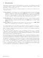
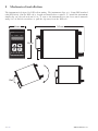
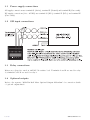
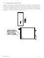
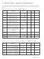
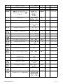
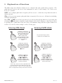
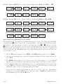
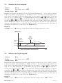
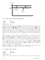
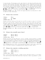
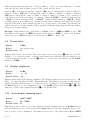
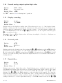
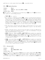
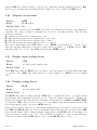
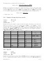
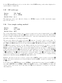
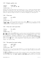
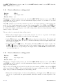
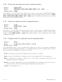
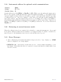
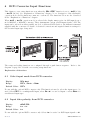
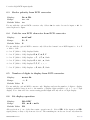
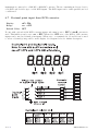
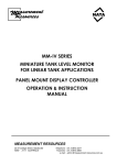
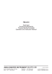
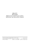
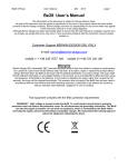
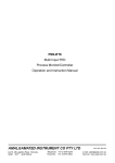
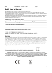
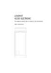
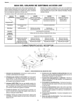
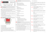
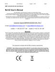
Model RM4-SSI
Synchronous Serial Interface (SSI)
DIN Rail Mount Display/Controller
Operation and Instruction Manual
AMALGAMATED INSTRUMENT CO PTY LTD
Unit 5, 28 Leighton Place Hornsby
NSW 2077 Australia
Telephone: +61 2 9476 2244
Facsimile: +61 2 9476 2902
ACN: 001 589 439
e-mail: [email protected]
Internet: www.aicpl.com.au
Table of Contents
1 Introduction
3
2 Mechanical installation
4
3 Electrical installation
5
4 Function tables - summary of setup functions
8
5 Explanation of functions
11
6 BCD Converter Input Functions
28
7 Specifications
32
8 Guarantee and service
33
2 of 33
RM4SSIMAN-2.2-0
1
Introduction
This manual contains information for the installation and operation of the RM4-SSI synchronous
serial interface monitor. Input to the RM4 can be configured as either binary or Gray code SSI
with number of bits selectable from 1 to 31.
There are three methods available for scaling the display choose which is most suitable from one
of the methods below.
Scaling Method 1 - The display can be scaled by using known data from the encoder and
entering the appropriate scaling values at the INPt function, see section 5.21 and SCLE
function, see section 5.22. The encoder sends data in the form of numbers which in use will
correspond to engineering units e.g. distance in mm. If it is known how the output from the
encoder corresponds to distance then the appropriate scaling values can be entered.
Scaling Method 2 - The second method requires the encoder to be placed in its zero position
and the display zeroed. The encoder is then moved to a known position e.g. a known distance
in mm and the value for this known position entered. See U.SCL function, section 5.26 and
Pbut, section 5.18.
Scaling Method 3 - By entering the values required at two known points (see USER SCLE
function 5.30). This method also allows the use of a calibration offset.
Two standard inbuilt relays provide alarm/control functions. Various combinations of one or two
optional extra relays, single or dual analog (4-20mA, 0-1V or 0-10V) retransmission or serial (RS232,
RS485 or RS422) communications and an isolated 12 or 24VDC isolated transmitter supply may
also be provided as an option.
Unless otherwise specified at the time of order, your RM4 has been factory set to a standard
configuration. Like all other RM4 series instruments the configuration and calibration is easily
changed by the user. Initial changes may require dismantling the instrument to alter PCB links,
other changes are made by push button functions.
Full electrical isolation between power supply, input voltage or current and retransmission output is
provided by the RM4, thereby eliminating grounding and common voltage problems. This isolation
feature makes the RM4 ideal for interfacing to computers, PLCs and other data acquisition devices.
The RM4 series of DIN Rail Process Modules are designed for high reliability in industrial applications. The 5 digit LED display provides good visibility, even in areas with high ambient light
levels. A feature of the RM4-SSI is the programmable display brightness function, this allows the
unit to be operated with low display brightness to reduce the instrument power consumption and
to improve readability in darker areas. To reduce power consumption in normal use the display
can be programmed to automatically dim or blank after a set time.
RM4SSIMAN-2.2-0
3 of 33
2
Mechanical installation
The instrument is designed for DIN rail mounting. The instrument clips on to 35mm DIN standard
rails (EN50022). Cut the DIN rail to length and install where required. To install the instrument
simply clip onto the rail as shown below. To remove the instrument lever the lower arm downwards
using a broad bladed screwdriver to pull the clip away from the DIN rail.
141mm
44mm
I
2
3
4
91mm
Rail
4 of 33
RM4SSIMAN-2.2-0
3
Electrical installation
The RM4 Meter is designed for continuous operation and no power switch is fitted to the unit. It
is recommended that an external switch and fuse be provided to allow the unit to be removed for
servicing. The terminal blocks allow for wires of up to 2.5mm2 to be fitted for power supply and
relays 1 and 2 or 1.5mm2 for input connections and optional outputs. Connect the wires to the
appropriate terminals as indicated below.
Refer to connection diagrams provided in this manual to confirm proper selection of voltage, polarity
and input type before applying power to the instrument. When power is applied the instrument
will cycle through a display sequence, indicating the software version and other status information,
this indicates that the instrument is functioning. Acknowledgement of correct operation may be
obtained by applying an appropriate input to the instrument and observing the resultant reading.
Note that the power supply type is factory configured. Check power supply type before connecting.
Relay outputs are voltage free contacts.
Electrical connections and data label (240VAC supply example)
RM4SSIMAN-2.2-0
5 of 33
3.1
Power supply connections
AC supply connections use terminal G (Active), terminal F (Neutral) and terminal E (Case earth).
DC supply connections (12 to 48VDC) use terminal G (DC-), terminal F (DC+) and terminal E
(Case earth).
3.2
SSI input connections
3.3
Relay connections
Relays are voltage free rated at 240VAC 5A resistive load. Terminals A and B are used for relay
1, terminals C and D are used for relay 2.
3.4
Optional outputs
Refer to the separate “RM4 Din Rail Meter Optional Output Addendum” for connection details
of optional outputs fitted.
6 of 33
RM4SSIMAN-2.2-0
3.5
Configuring the input board
There are two user configurable links on the input circuit board, these are LK3 and LK4 labeled
“TERM 1” and “TERM 2”. These links are provided to reduce reflections in long cable runs and
are generally only required in cases where long cable runs are used but for most applications can
be left in place. If the link settings need to be changed refer to the drawing below for instructions
on removal of circuit boards. Refer to the separate “RM4 DIN Rail Meter Optional Output
Addendum” booklet supplied if optional outputs are fitted.
RM4SSIMAN-2.2-0
7 of 33
4
Function tables - summary of setup functions
Note: the order in which the functions appear on the display may not be exactly as shown below.
The availability and order of functions is determined by choice of function settings and options
fitted.
Functions in this first table are available in FUNC or CAL mode
Display
Function
Range
Default
Your Ref/Page
record
AxLo
Low setpoint value for
designated alarm relay x
Any display
value or OFF
OFF
See
4.1
5.1 / 13
AxHi
High setpoint value for
designated alarm relay x
Any display
value or OFF
OFF
See
4.1
5.2 / 13
AxHY
Hysteresis value for the
designated alarm relay x.
0 to 9999
10
See
4.1
5.3 / 14
Axtt
Trip time delay for the
designated alarm relay x.
0 to 9999
0
See
4.1
5.4 / 14
Axrt
Reset time delay for the
designated alarm relay x.
0 to 9999
0
See
4.1
5.5 / 15
Axn.o
or
Axn.c
Alarm relay x action to
normally open (de-energised) or
normally closed (energised)
Axn.o or
Axn.c
Axn.o
See
4.1
5.6 / 15
AxSP
or
Axt1
etc.
Relay operation independent
setpoint or trailing setpoint
(∗ Optional)
AxSP or
Axt1 etc.
AxSP
See
4.1
5.7 / 15
P.SEt
Preset value
Any display
value
0
5.8 / 16
brGt
Display brightness level
1 to 15
15
5.9 / 16
d.oFF
SECS
Auto display dimming timer
0 to 9999
0
5.10 / 16
(∗ Optional)—this function will only be accessible if the relevant option is fitted
Functions in this second table are available only in CAL mode or if ACCS is set to ALL
Display
Function
Range
Default
Your Ref/Page
record
REC_
Analog output option low
display value (∗ Optional)
Any display
value
0
5.11 / 17
REC~
Analog output option high
display value (∗ Optional)
Any display
value
1000
5.12 / 17
REC_
Ch2
Second analog output option
low display value (∗ Optional)
Any display
value
0
5.13 / 17
REC~
Ch2
Second analog output option
high display value (∗ Optional)
Any display
value
1000
5.14 / 18
(∗ Optional)—this function will only be accessible if the relevant option is fitted
8 of 33
RM4SSIMAN-2.2-0
drnd
Display rounding
1 to 5000
1
5.15 / 18
dCPt
Decimal point
0, 0.1 etc.
0
5.16 / 18
FLtr
Digital filter
0 to 8
2
5.17 / 18
Pbut
P button function (for
instruments with front P
button)
NONE, Hi,
Lo, HiLo,
ZERO or
P.SEt
NONE
5.18 / 19
ACCS
Access mode
OFF, EASY,
NONE or ALL
OFF
5.19 / 19
SPAC
Setpoint access mode
A1, A1-2 etc.
A1
5.20 / 20
INPt
Display input scaling factor
1 to any
positive display
value
1
5.21 / 20
SCLE
Display scaling factor
1 to any
display value
1
5.22 / 20
SSI
bits
Number of input bits
1 to 31
1
5.23 / 21
SIGN
Sign bit
on or OFF
OFF
5.24 / 21
SSI
CodE
SSI code type
bin or GRAY
bin
5.25 / 22
U.SCL
User simple scaling method
on or OFF
OFF
5.26 / 22
dISP
RAtE
Display update rate
1, 2, 4, 8, 16
or 32
4
5.27 / 23
CLr
ZERO
Clear zero
n/a
n/a
5.28 / 23
CLr
U.SCL
Clear user scale operation
n/a
n/a
5.29 / 23
USER
SCLE
Two point live input scaling
on or OFF
OFF
5.30 / 23
CAL1
First live input calibration
scaling point
Any display
value
n/a
5.31 / 24
CAL2
First live input calibration
scaling point
Any display
value
n/a
5.32 / 24
CAL
OFSt
Calibration offset
Any display
value
n/a
5.33 / 25
SEt
OPER
Set display operation
SSI, bc 8 or
bc24
SSI
6.6 / 29
SSI
RAtE
SSI clock frequency
Lo or Hi
Hi
5.35 / 25
bAUd
RAtE
Baud rate for serial
communications (∗ Optional)
300, 600,
1200, 2400,
4800, 9600,
19.2 or 38.4
9600
5.36 / 26
(∗ Optional)—this function will only be accessible if the relevant option is fitted
RM4SSIMAN-2.2-0
9 of 33
PrtY
Parity for serial communications
(∗ Optional)
NONE, EUEN
or odd
NONE
5.37 / 26
O.Put
Output for serial
communications (∗ Optional)
dISP, Cont,
POLL, A.buS
or M.buS
Cont
5.38 / 26
Addr
Instrument address for serial
communications (∗ Optional)
0 to 31
0
5.39 / 27
(∗ Optional)—this function will only be accessible if the relevant option is fitted
4.1
Relay table
Record your relay settings in the table below. Note: relays 3 and 4 are optionally fitted.
Display
Relay 1
Relay 2
Relay 3
Relay 4
AxLo
AxHi
AxHY
Axtt
Axrt
Axn.o or Axn.c
AxSP or Axt1 etc.
10 of 33
n/a
RM4SSIMAN-2.2-0
5
Explanation of functions
The RM4 setup and calibration functions are configured through a push button sequence. The
push buttons located at the front of the instrument are used to alter settings. Two basic access
modes are available:
FUNC mode (simple push button sequence) allows access to commonly set up functions such as
alarm setpoints.
CAL mode (power up sequence plus push button sequence) allows access to all functions including
calibration parameters.
Once CAL or FUNC mode has been entered you can step through the functions, by pressing and
releasing the F push button, until the required function is reached. Changes to functions are made
by pressing the or push button (in some cases both simultaneously) when the required function is
reached. See the flow chart example on the following page.
P
P
Entering FUNC Mode
1. Remove power from
the instrument. Hold in the F
button and reapply power.
The display will indicate
CAL as part of the
"wake up messages" when
the CAL message is seen
you can release the
button.
F
F
2. When the "wake up"
messages have finished
and the display has settled
down to its normal reading
press, then release the
F button.
P
F
3. Within 2 seconds of
releasing the F button
press, then release
the ^ and
buttons
together. The display will
now indicate FUNC followed
by the first function.
No special power up procedure
is required to enter FUNC mode.
P
F
P
1. When the "wake up"
messages have finished
and the display has settled
down to its normal reading
press, then release the
F button.
F
2. Within 2 seconds of
releasing the F button
press, then release
the ^ and
buttons
together. The display will
now indicate FUNC followed
by the first function.
^
Entering CAL Mode
^
Note: If step 1 above has been completed then the
instrument will remain in this CAL mode state until
power is removed. i.e. there is no need to repeat step 1
when accessing function unless power has been removed.
RM4SSIMAN-2.2-0
11 of 33
Example: Entering FUNC mode to change alarm 1 high function A1Hi from OFF to 100
Press & release F
then press
^v
1 0 0
F U N C
Press & release
F until
Press & release
Press & release
F
P or F until
A 1 H i
F U N C
Press & release
O F F
^ until
E n d
Example: Entering CAL mode to change decimal point function dCPt from 0 to 0.02
Switch off
instrument
Press & release F
then press
^v
.0 0 2
Press & hold
F
F U N C
Switch on
instrument
Press & release
F until
Press & release
Press & release
F
P or F until
Hold F until
C A L
d C P t
F U N C
0
Release F
Press & release
^ until
E n d
Easy alarm relay adjustment access facility
The display has an easy alarm access facility which allows access to the alarm setpoints simply
by pressing the F button at the front of the instrument. The first setpoint will then appear
and changes to this setpoint may be made to this setpoint via the ^ or v buttons. Press the
F button to accept any changes or to move on to the next setpoint. Note: this easy access also
functions in the same manner for the PI control setpoint (relay and/or analog PI output) if PI
control is available. The instrument must be set in the manner described below to allow the easy
access facility to work:
1. The R.INP function must be set to SPAC or the ACCS function must be set to EASY.
2. At least one alarm must have a setpoint, nothing will happen if all the alarm setpoints are
set to OFF.
3. The SPAC function must be set to allow access to the relays required e.g. if set to A1-2
then the easy access will work only with alarm relays 1 and 2 even if more relays are fitted.
4. The instrument must be in normal measure mode i.e. if the instrument is powered up so that
it is in CAL mode then the easy access will not function. If in doubt remove power from the
instrument, wait for a few seconds then apply power again.
5. If the easy access facility is used then the only way to view or alter any other function
settings is to power up via CAL mode i.e. there is no entry to FUNC mode functions unless
the instrument is powered up in CAL mode.
12 of 33
RM4SSIMAN-2.2-0
5.1
Alarm relay low setpoint
Display:
AxLo
Range:
Any display value or OFF
Default Value:
OFF
Displays and sets the low setpoint value for the designated alarm relay x. Note x will be replaced
by the relay number when displayed e.g. A1Lo for relay 1. Use this low setpoint function if a
relay operation is required when the display value becomes equal to or less than the low setpoint
value. To set a low alarm value go to the AxLo function and use the ^ or v push buttons to set
the value required then press F to accept this value. The low alarm setpoint may be disabled by
pressing the ^ and v push buttons simultaneously. When the alarm is disabled the display will
indicate OFF. If the relay is allocated both a low and high setpoint then the relay will activate
when the value displayed moves outside the band set by the low and high setpoints. The value at
which the relay will reset is controlled by the AxHY function.
Example:
If A1Lo is set to 10 then relay 1 will activate when the display value is 10 or less.
Display Value
AxLo
plus
AxHY
Relay
activates
at this value
or below
Relay
resets
above this
value
AxHY value
AxLo
Alarm low operation with hysteresis
5.2
Time
Alarm relay high setpoint
Display:
AxHi
Range:
Any display value or OFF
Default Value:
OFF
Displays and sets the high setpoint value for the designated alarm relay x. Note x will be replaced
by the relay number when displayed e.g. A1Hi for relay 1. Use this high setpoint function if a
relay operation is required when the display value becomes equal to or more than the low setpoint
value. To set a high alarm value go to the AxHi function and use the ^ or v push buttons to
set the value required then press F to accept this value. The high alarm setpoint may be disabled
by pressing the ^ and v push buttons simultaneously. When the alarm is disabled the display
will indicate OFF. If the relay is allocated both a low and high setpoint then the relay will activate
when the value displayed moves outside the band set by the low and high setpoints. The value at
which the relay will reset is controlled by the AxHY function.
Example:
If A1Hi is set to 100 then relay 1 will activate when the display value is 100 or higher.
RM4SSIMAN-2.2-0
13 of 33
Display Value
AxHi
AxHY value
AxHi
minus
AxHY
Relay
activates
at this value
or above
Relay
resets
below this
value
Alarm high operation with hysteresis
5.3
Time
Alarm relay hysteresis (deadband)
Display:
AxHY
Range:
0 to 9999
Default Value:
10
Displays and sets the alarm relay hysteresis limit for the designated relay x. Note x will be replaced
by the relay number when displayed e.g. A1HY for relay 1. To set a relay hysteresis value go to the
AxHY function and use the ^ or v push buttons to set the value required then press F to accept
this value. The hysteresis value is common to both high and low setpoint values. The hysteresis
value may be used to prevent too frequent operation of the relay when the measured value is rising
and falling around setpoint value. e.g. if A1HY is set to zero the alarm will activate when the
display value reaches the alarm setpoint (for high alarm) and will reset when the display value falls
below the setpoint, this can result in repeated on/off switching of the relay at around the setpoint
value.
The hysteresis setting operates as follows: In the high alarm mode, once the alarm is activated
the input must fall below the setpoint value minus the hysteresis value to reset the alarm. e.g. if
A1Hi is to 50.0 and A1Hy is set to 3.0 then the setpoint output relay will activate once the
display value goes to 50.0 or above and will reset when the display value goes below 47.0 i.e. at
46.9 or below. In the low alarm mode, once the alarm is activated the input must rise above the
setpoint value plus the hysteresis value to reset the alarm. e.g. if A1Lo is to 20.0 and A1Hy
is set to 10.0 then the alarm output relay will activate when the display value falls to 20.0 or
below and will reset when the display value goes above 30.0 i.e at 30.1 or above. The hysteresis
units are expressed in displayed engineering units.
Example: If A1Hi is set to 100 and A1HY is set to 10 then relay 1 will activate when the
display value is 100 or higher and will reset at a display value of 89 or lower.
5.4
Alarm relay trip time
Display:
Axtt
Range:
0 to 9999
Default Value:
0
Displays and sets the alarm trip time in seconds. The trip time is common for both alarm high and
14 of 33
RM4SSIMAN-2.2-0
low setpoint values. The trip time provides a time delay before the alarm relay will activate when
an alarm condition is present. The alarm condition must be present continuously for the whole trip
time period before the alarm will activate. If the input moves out of alarm condition during this
period the timer will reset and the full time delay will be restored. This trip time delay is useful
for preventing an alarm trip due to short non critical deviations from setpoint. The trip time is
selectable over 0 to 9999 seconds. To set a trip time value go to the Axtt function and use the
^ or v push buttons to set the value required then press F to accept this value.
Example: If A1tt is set to 5 seconds then the display must indicate an alarm value for a full 5
seconds before relay 1 will activate.
5.5
Alarm relay reset time
Display:
Axrt
Range:
0 to 9999
Default Value:
0
Displays and sets the alarm reset delay time in seconds. The reset time is common for both alarm
high and low setpoint values. With the alarm condition is removed the alarm relay will stay in
its alarm condition for the time selected as the reset time. If the input moves back into alarm
condition during this period the timer will reset and the full time delay will be restored. The reset
time is selectable over 0 to 9999 seconds. To set a reset time value go to the Axrt function and
use the ^ or v push buttons to set the value required then press F to accept this value.
Example: If A1rt is set to 10 seconds then the resetting of alarm relay 1 will be delayed by 10
seconds.
5.6
Alarm relay normally open/closed
Display:
Axn.o or Axn.c
Range:
Axn.o or Axn.c
Default Value:
Axn.o
Displays and sets the setpoint alarm relay x action to normally open (de-energised) or normally
closed (energised), when no alarm condition is present. Since the relay will always open when power
is removed a normally closed alarm is often used to provide a power failure alarm indication. To
set the alarm relay for normally open or closed go to the Axn.o or Axn.c function and use the ^
or v push buttons to set the required operation then press F to accept this selection. Example:
If set to A1n.o alarm relay 1 will be open circuit when the display is outside alarm condition and
will be closed (short circuit across terminals) when the display is in alarm condition.
5.7
Alarm relay setpoint or trailing operation
Display:
AxSP or Axt1 etc.
Range:
AxSP or Axt1 etc.
Default Value:
AxSP
Relay operation independent setpoint or trailing setpoint, this function will not be seen unless
extra optional relays are fitted. Each alarm relay, except relay 1, may be programmed to operate
RM4SSIMAN-2.2-0
15 of 33
with an independent setpoint value or may be linked to operate at a fixed difference to another
relay setpoint, known as trailing operation. The operation is as follows:
Alarm 1 (AI) is always independent. Alarm 2 (A2) may be independent or may be linked to
Alarm 1. Alarm 3 (A3) may be independent or may be linked to Alarm 1 or Alarm 2. Alarm 4
(A4) may be independent or may be linked to Alarm 1, Alarm 2 or Alarm 3. The operation of
each alarm is selectable by selecting, for example, (Alarm 4) A4.SP = Alarm 4 normal setpoint
or A4.t1 = Alarm 4 trailing Alarm 1 or A4.t2 = Alarm 4 trailing Alarm 2 or A4.t3 = Alarm
4 trailing Alarm 3. For trailing set points the setpoint value is entered as the difference from the
setpoint being trailed. If the trailing setpoint is to operate ahead of the prime setpoint then the
value is entered as a positive number and if operating behind the prime setpoint then the value is
entered as a negative number.
Example: With Alarm 2 set to trail alarm 1, if A1Hi is set to 1000 and A2Hi is set to 50
then Alarm 1 will activate at 1000 and alarm 2 will activate at 1050 (i.e. 1000 + 50). If Alarm
2 had been set at -50 then alarm 2 would activate at 950 (i.e. 1000 – 50).
5.8
Preset value
Display:
P.SEt
Range:
Any display value
Default Value:
0
Displays and sets the preset value. The preset value can be used via the P button to force the
display to go to the preset value. A change in the input value will then cause the display to rise
or fall from the preset value. To use the P button to operate the preset function set the P.but
function to P.SEt.
5.9
Display brightness
Display:
brGt
Range:
1 to 15
Default Value:
15
Displays and sets the digital display brightness. The display brightness is selectable from 1 to 15,
where 1 = lowest intensity and 15 = highest intensity. This function is useful for improving the
display readability in dark areas or to reduce the power consumption of the instrument. See also
the duLL function. To set brightness level go to the brGt function and use the ^ or v push
buttons to set the value required then press F to accept this value.
5.10
Auto display dimming timer
Display:
d.oFF SECS
Range:
0 to 9999
Default Value:
0
This function allows a time to be set after which the display brightness (set by the brGt function)
will automatically be set to the level set at the duLL function. The auto dimming feature can be
used to reduce power consumption. The function can be set to any value between 0 and 9999
16 of 33
RM4SSIMAN-2.2-0
seconds. A setting of 0 disables the auto dimming. The display brightness can be restored by
pressing any of the instruments front push buttons. The display brightness will also be restored
whilst one or more alarm relays is activated. In normal display mode (i.e. not in CAL mode) there
is a 2 minute delay period after the instrument is switched on during which the automatic display
dimming will not operate. If any of the front pusbuttons are pressed during this period this 2
minute delay will be canceled.
5.11
Analog output option low value
Display:
REC_
Range:
Any display value
Default Value:
0
Seen only when analog retransmission option fitted. Refer to the separate “RM4 Din Rail Meter
Optional Output Addendum” booklet supplied when this option is fitted for wiring details and link
settings. Displays and sets the analog retransmission (4–20mA, 0–1V or 0–10V, link selectable)
output low value (4mA or 0V) in displayed engineering units. To set the analog output low value
go to the REC_ function and use the ^ or v push buttons to set the required value then press
F to accept this selection.
Example:If it is required to retransmit 4mA when the display indicates 0 then select 0 in this
function using the ^ or v button.
5.12
Analog output option high value
Display:
REC~
Range:
Any display value
Default Value:
1000
Seen only when analog retransmission option fitted. Refer to the separate “RM4 Din Rail Meter
Optional Output Addendum” booklet supplied when this option is fitted for wiring details and link
settings. Displays and sets the analog retransmission (4–20mA, 0–1V or 0–10V, link selectable)
output high display value (20mA, 1V or 10V) in displayed engineering units. To set the analog
output high value go to the REC~ function and use the ^ or v push buttons to set the required
value then press F to accept this selection.
Example: If it is required to retransmit 20mA when the display indicates 50 then select 50 in
this function using the ^ or v button.
5.13
Second analog output option low value
Display:
REC_
Ch2
Range:
Any display value
Default Value:
0
See REC_ function 5.11 for description of operation.
RM4SSIMAN-2.2-0
17 of 33
5.14
Second analog output option high value
Display:
REC~
Ch2
Range:
Any display value
Default Value:
1000
See REC~ function 5.12 for description of operation.
5.15
Display rounding
Display:
drnd
Range:
1 to 5000
Default Value:
1
Displays and sets the display rounding value. This value may be set to 1 - 5000 displayed units.
Display rounding is useful for reducing the instrument resolution without loss of accuracy in applications where it is undesirable to display to a fine tolerance. To set the display rounding value
go to the drnd function and use the ^ or v push buttons to set the required value then press
F to accept this selection.
Example: If set to 10 the display values will change in multiples of 10 only i.e. display moves
from 10 to 20 to 30 etc.
5.16
Decimal point
Display:
dCPt
Range:
0, 0.1 etc.
Default Value:
0
Displays and sets the decimal point. By pressing the ^ or v pushbutton at the dCPt function
the decimal point position may be set. The display will indicate as follows: 0 (no decimal point),
0.1 (1 decimal place), 0.02 (2 decimal places), 0.003 (3 decimal places) or 0.0004(4 decimal
places). Note if the decimal point is altered the display may need to be recalibrated and alarm etc.
settings checked.
5.17
Digital filter
Display:
FLtr
Range:
0 to 8
Default Value:
2
Displays and sets the digital filter value. Digital filtering uses a weighted average method of
determining the display value and is used for reducing display value variation due to short term
interference. The digital filter range is selectable from 0 to 8, where 0 = none and 8 = most
filtering. Use ^ or v at the FLtr function to alter the filter level if required. Note that the
higher the filter setting the longer the display may take to reach its final value when the input is
changed, similarly the relay operation and any output options will be slowed down when the filter
setting is increased. To set the digital filter value go to the FLtr function and use the ^ or v
18 of 33
RM4SSIMAN-2.2-0
push buttons to set the required value then press F to accept this selection.
5.18
P button function
Display:
Pbut
Range:
NONE, Hi, Lo, HiLo, ZERO or P.SEt
Default Value:
NONE
P button function - a only applicable models with front panel P buttons. The P button may be
set to operate one of the following selections:
• NONE - P has no operation.
• Hi - Peak memory. This function allows the P to be used to view and reset the peak memory.
The peak memory is the maximum positive display value achieved since the peak memory
was last reset. To view the peak memory press the P momentarily, the display will show
the indicator P Hi followed by the peak reading. This peak reading will be retained on the
display for approximately 20 seconds before returning to “live” display readings, alternatively
the display can be forced to return to “live” measurement by pressing the F. To reset the
peak memory hold the P pressed for 3 seconds or remove power to the display.
• Lo - Valley memory. Operates in the same manner as the Hi function above but operates
on the lowest value in memory. The indicator P Lo will be seen prior to the valley memory
value.
• HiLo - Peak/valley memory. Operates in the same manner as the Hi and Lo memories
but allows toggling between high and low values i.e. press once momentarily to view peak
high and again momentarily to view peak low.
• ZERO - display zero. Either the U.SCL or USER SCLE function must be set to on if the
ZERO operation is required. When the ZERO operation is used the display will show the
message ZERO and the display value will fall to zero. All zero operations can be reset i.e.
cleared via the CLr ZERO function if required. Hold the P button pressed for 2-3 seconds
to activate the zero operation.
• P.SEt - preset value. Either the U.SCL or USER SCLE function must be set to on if the
P.SEt operation is required. The P button can be used to force the display to the preset
value, this preset value is set at the P.SEt function. Any changes in the output from the
sensor will then add or subtract from the displayed preset value. Hold the P button pressed
for 2-3 seconds to activate the preset operation.
5.19
Access mode
Display:
ACCS
Range:
OFF, EASY, NONE or ALL
Default Value:
OFF
Access mode - the access mode function ACCS has four possible settings namely OFF, EASY,
NONE and ALL. If set to OFF the mode function has no effect on alarm relay operation. If set
to EASY the “easy alarm access” mode will be activated. Refer to “Easy alarm relay adjustment
access facility” page 12. If set to NONE there will be no access to any functions via FUNC mode,
RM4SSIMAN-2.2-0
19 of 33
entry via CAL mode must be made to gain access to alarm and calibration functions. If set to ALL
then access to all functions, including calibration functions, can be gained via FUNC mode.
5.20
Setpoint access mode
Display:
SPAC
Range:
A1, A1-2 etc.
Default Value:
A1
Setpoint access - sets the access via FUNC mode and “easy alarm access” mode to the alarm relay
setpoints. Two relays are fitted as standard, two more are optionally available. The following
choices are available:
A1 - Allows setpoint access to alarm relay 1 only.
A1-2 - Allows setpoint access to alarm relays 1 and 2 only.
A1-3 - Allows setpoint access to alarm relays 1, 2 and 3
A1-4 - Allows setpoint access to alarm relays 1, 2, 3 and 4
The remote input function (R.INP) must be set to SP.AC for this function to operate. Note:
Only the setpoints which have been given a value will be accessible e.g. if A1Hi is set to OFF
then there will be no access to the A1Hi function when SPAC is used.
5.21
Display input scaling factor
Display:
INPt
Range:
1 to any positive display value
Default Value:
1
The INPt factor and the SCLE factor are used to scale the display to read in engineering units
e.g. metres. The INPt value must always be a whole number, see SCLE below for formula
used.
5.22
Display scaling factor
Display:
SCLE
Range:
1 to any display value
Default Value:
1
The SCLE value is used together with the INPt value to calculate the value to be displayed from
the SSI input value transmitted from the encoder. These two functions are used to calculate the
display value and are used only when the alternative scaling methods of U.SCL and USER SCLE
are both set to OFF. The scale factor can be set to any display value and the decimal point value
seen at this function will be set by the dCPt function.
If the relevant details of the encoder and display requirements are known the easiest way to find
the INPt and SCLE values is to use the maximum output value from the encoder as the INPt
value and the display value for this maximum output value as the SCLE value. For example a 16
bit encoder has an output of 0 to 65535. If you wish this to display 0 to 1500 over the full range
of the encoder then set the INPt value to 65535 and the SCLE value to 1500.
20 of 33
RM4SSIMAN-2.2-0
The display value is calculated in the following manner:
Display value =
Value sent from encoder × SCLE
INPt
Example: A 12 bit SSI encoder will give an output in the range 0 to 4095
are used). The display is to be scaled to show 0.0 to 359.9 over this 12 bit
point the INPt value could be set to 4095 and the SCLE value set to
i.e. at one quarter output from the encoder (i.e. 1024) the display value is
Display value =
(if only positive values
range. With 1 decimal
359.9 to achieve this
calculated from:
1024 × 359.9
4095
i.e. Display value = 90.0
5.23
Number of input bits from encoder
Display:
SSI bits
Range:
1 to 31
Default Value:
1
Displays and selects the number of input bits which the display will interpret as incoming data.
This can be set from 1 to 31 bits. For example with an INPt of 1 and a SCLE of 1 and 12
bits selected the display will show from 0 to 4095, i.e. the 12 bit binary number range, before
returning to 0. Note: If the SIGN function is set to on then the maximum range displayed in
this example is -2048 and 2047. The table which follows gives some examples of the effect of
INPt, SCLE, SSI bitS and SIGN settings.
INPt
SCLE
SSI bitS
SIGN
Viewable display range
1
1
12
OFF
0 to 4095
1
-1
12
OFF
0 to -4095
1
1
12
on
-2048 to 2047
1
-1
12
on
-2047 to 2048
1
2
12
OFF
0 to 8191
2
1
12
OFF
0 to 2047
1
1
13
OFF
0 to 8191
1
1
14
OFF
0 to 16383
1
1
20
OFF
0 to 1048575
1
1.00
20
OFF
0 to 1048.58
8192
1000
12
OFF
0 to 500
5.24
Sign bit
Display:
SIGN
Range:
on or OFF
Default Value:
OFF
Displays and sets the sign bit enabling. With the SIGN function set to on the data is interpreted
as a twos compliment signed number, masked to the number of bits set by the SSI bitS function.
RM4SSIMAN-2.2-0
21 of 33
See the SSI bitS function above for the effect of the SIGN setting on the values displayed for
a given number of input bits.
5.25
SSI code type
Display:
SSI CodE
Range:
bin or GRAY
Default Value:
bin
The input type can be set to bin for binary or to GRAY for gray code SSI to match the output
type from the sensor.
5.26
User simple scaling method
Display:
U.SCL
Range:
on or OFF
Default Value:
OFF
Two point scaling method using a zero or preset operation via a remote input switch or front P
button as the first scaling point and a F button operation to scale as second point. This method
provides a simple scaling method without the need to enter the setup functions and is generally
used where scaling is to be changed frequently.
The user scale function allows the front panel F button to be used to enter a scale value. To
operate by this method the U.SCL function must be set to on. If this method of scaling is used
the INPt and SCLE functions are not used and the USER SCLE function must be set to OFF.
The P button must be used to zero the display with the encoder in its zero position or set the
display to a preset value with the encoder at a known position prior to the U.SCL operation. See
P.but (section 5.18) function. The operator then simply moves the encoder to a different know
position and then holds the F button pressed for approximately 2 seconds. The message SCALE
will then appear followed by the previous scale value. The value can now be adjusted via the ^
or v pushbutton. The F button is pressed to accept the change or the P button can be pressed
to abort the scaling. If an error occurs such as trying to give a scaling value to a display reading
which is zero then the message SCALE Error will be seen.
Example: the sensor is moved to its zero position and a ZERO operation carried out via the P
button. The sensor is then moved a known distance and the U.SCL operation is carried out via
the F button.
Notes: Easy access (ACCS function set to EASY) to alarm functions cannot be used if U.SCL is
set to on. If ACCS is set to EASY or CAL when U.SCL is set to on then FUNC mode entry will
operate as the “easy access” mode and entry via CAL mode will have to be made to access any
other functions.
22 of 33
RM4SSIMAN-2.2-0
5.27
Display update rate
Display:
dISP RAtE
Range:
1, 2, 4, 8, 16 or 32
Default Value:
4
Displays and sets the display update rate in updates per second e.g. if 4 is selected then the display
will update four times per second. The lowest satisfactory update rate should be chosen. If too
high a rate is selected then the rapid update may cause an apparent flickering of the display. The
update rate affects the display only and does not affect the sampling rate, alarm update etc.
5.28
Clear zero
Display:
CLr ZERO
Range:
n/a
Default Value:
n/a
Allows any zero operations performed via the remote input or P button to be cleared. Pressing
the ^ and v buttons simultaneously will clear the zero offset, the message CLrd will be seen,
confirming the zero clearing operation is completed.
5.29
Clear user scale operation
Display:
CLr U.SCL
Range:
n/a
Default Value:
n/a
The display scaling via the U.SCL function operation can be cleared at this function. Pressing the
^ and v buttons simultaneously will clear the user scaling and will cause the scaling to revert
to a 1:1 equivalent i.e. equivalent to INPt function set to 1 and SCLE function set to 1. Note
that clearing the user scale will not clear any zero or preset operations, the CLR ZERO function
must be used to clear any zero offsets. If necessary the preset value can be changed at the P.SEt
function and the P button or remote input used to activate the preset operation to return the
display to the required scaling.
5.30
Two point live input scaling
Display:
USER SCLE
Range:
on or OFF
Default Value:
OFF
Allows selection of two point live input calibration to be used when this function is set to on.
This method allows scaling without the need to calculate the required scaling from the SSI encoder/sensor data.
The CAL1 and CAL2 functions described below can then be used to scale the display. If required
the CAL OFSt function can be used to make an adjustment to add or subtract an offset value
across the display range. The CAL1, CAL2 and CAL OFSt functions will only be seen when
RM4SSIMAN-2.2-0
23 of 33
the USER SCLE function is set to on. Note: the U.SCL function must be set to OFF when the
USER SCLE function is used.
5.31
First calibration scaling point
Display:
CAL1
Range:
Any display value
Default Value:
n/a
This method of display scaling is used only when the USER SCLE function is set to on. CAL1
and CAL2 are used together to scale the instruments display, values for both must be set when
using this scaling method.
The CAL1 function sets the first calibration point for live input calibration. When using this
method a “live” signal input must be present at the input terminals. Note: CAL1 and CAL2 can
be set independently i.e. it is not necessary to perform a CAL2 operation directly after a CAL1.
Note that some display rounding may occur if the scaling values entered are larger than the normal
binary or Gray code values.
The procedure for entering the first scaling point is:
1. Ensure that an input signal of a know value from an encoder etc. is present at the input
terminals, this will normally be at the low end of the range.
2. At the CAL1 function press ^ and v simultaneously, then release them. The display will
indicate the live input value. Do not be concerned at this stage if the live input display value
is not what is required.
3. Press then release the F button. The display will indicate SCL1 followed by a value. Use
the ^ or v button to change this value to the required display scale value at this input.
Press the F button to accept changes, the display will show CAL End and will then move
on to the next function.
5.32
First calibration scaling point
Display:
CAL2
Range:
Any display value
Default Value:
n/a
This method of display scaling is used only when the USER SCLE function is set to on. CAL1
and CAL2 are used together to scale the instruments display, values for both must be set when
using this scaling method.
The second point scaling is performed in exactly the same manner as CAL1 except that SCL2
will be seen instead of SCL1. It is essential that the live input is different in value to the CAL1
input. The procedure for entering the second scaling point is:
1. Ensure that an input signal of a know value (different to the input used at CAL1) from an
encoder etc. is present at the input terminals, this will normally be at the high end of the
range.
24 of 33
RM4SSIMAN-2.2-0
2. At the CAL2 function press ^ and v simultaneously, then release them. The display will
indicate the live input value. Do not be concerned at this stage if the live input display value
is not what is required.
3. Press then release the F button. The display will indicate SCL2 followed by a value. Use
the v or ^ button to change this value to the required display scale value at this input.
Press the F button to accept changes, the display will show CAL End and will then move
on to the next function.
5.33
Calibration offset
Display:
CAL OFSt
Range:
Any display value
Default Value:
n/a
This function will only be seen and can only be used if the USER SCLE function is set to on.
The calibration offset is a single point adjustment which can be used to alter the calibration scaling
values across the entire measuring range without affecting the calibration slope. This method can
be used instead of performing a two point calibration when a constant measurement error is found
to exist across the entire range. To perform a calibration offset press the ^ and v buttons
simultaneously at the CAL OFSt function. A ”live” reading from the input will be seen, make a
note of this reading. Press the F button, the message SCLE will now be seen followed by the last
scale value in memory. Use the ^ or v button to adjust the scale value to the required display
value for that input. For example if the “live” input reading was 50 and the required display value
for this input was 70 then adjust the SCLE value to 70.
5.34
Set display operation
Display:
SEt OPER
Range:
SSI, bc 8 or bc24
Default Value:
SSI
Allows selection of one of the three main operation mode. Select SSI if the input is an SSI
signal (binary or Gray code) from encoder etc. The remaining two modes are for use only when the
instrument is connected to a RM-BC or RM4-BC converter. The two remaining modes are bc8 for
8 bit BCD and bc24 for up to 24 bit BCD inputs. The BCD input can be either parallel, strobed
or addressed.
5.35
SSI clock frequency
Display:
SSI RAtE
Range:
Lo or Hi
Default Value:
Hi
Allows settings of Lo (90kHz) or Hi (600kHz) clock frequencies. The normal setting is Hi. Use
Lo only if communications difficulties are experienced due to long cable runs.
RM4SSIMAN-2.2-0
25 of 33
5.36
Baud rate for optional serial communications
Display:
bAUd RAtE
Range:
300, 600, 1200, 2400, 4800, 9600, 19.2 or 38.4
Default Value:
9600
Set baud rate - seen only with serial output option. Refer to the separate “RM4 Din Rail Meter
Optional Output Addendum” booklet supplied when optional outputs are fitted. Select from 300,
600, 1200, 2400, 4800, 9600, 19.2 or 38.4 baud. The baud rate should be set to match
the device being communicated with.
5.37
Parity for optional serial communications
Display:
PrtY
Range:
NONE, EUEN or odd
Default Value:
NONE
Set parity - seen only with serial output option. Refer to the separate “RM4 Din Rail Meter
Optional Output Addendum” booklet supplied when optional outputs are fitted. Select parity
check to either NONE, EUEN or odd. The parity should be set to match the device being
communicated with.
5.38
Output mode for optional serial communications
Display:
O.Put
Range:
dISP, Cont, POLL, A.buS or M.buS
Default Value:
Cont
Set serial interface mode - seen only with serial output option. Refer to the separate “RM4 Din
Rail Meter Optional Output Addendum” booklet supplied when optional outputs are fitted. Allows
user to select the serial interface operation as follows:
disP - sends image data from the display without conversion to ASCII.
Cont - sends 8 bit ASCII form of display data at a rate typically 90% of the sample rate.
POLL - controlled by computer or PLC as host. Host sends command via RS232/485 and
instrument responds as requested.
A.buS - is a special communications mode used with Windows compatible optional PC download
software. Refer to the user manual supplied with this optional software.
M.bus - Modbus RTU protocol.
26 of 33
RM4SSIMAN-2.2-0
5.39
Instrument address for optional serial communications
Display:
Addr
Range:
0 to 31
Default Value:
0
Set unit address for polled (POLL) or M.buS mode (0 to 31)) - seen only with serial output option.
Refer to the separate “RM4 Din Rail Meter Optional Output Addendum” booklet supplied when
optional outputs are fitted. Allows several units to operate on the same RS485 interface reporting
on different areas etc. The host computer or PLC may poll each unit in turn supplying the
appropriate address. The unit address ranges from 0 to 31 (DEC) but is offset by 32 (DEC) to
avoid clashing with ASCII special function characters (such as <STX> and <CR>). Therefore 32
(DEC) or 20 (HEX) is address 0, 42 (DEC) or 2A (HEX) is address 10. Do not use address 0 in
M.buS mode.
5.40
Returning to normal measure mode
When the calibration has been completed it is advisable to return the instrument to the normal
mode (where calibration functions are less likely to be tampered with). To return to normal mode,
turn off power to the instrument, wait a few seconds and then restore power.
5.41
Error Messages
• -or- - this message means that the number being received is too big to display e.g. 12345
cannot be displayed on a 4 digit display.
• SCALE Error - this message means that an error occurred whilst attempting to scale
the display. Check that the sensor is connected correctly and that the scaling method was
followed correctly.
RM4SSIMAN-2.2-0
27 of 33
6
BCD Converter Input Functions
This chapter covers extra functions seen when the SEt OPER function is set to bc8 (8 bit)
or bc24 (24 bit). See “Explanation of Functions” chapter 5 for a description of the alternative
operation mode and for functions common to each mode. The functions below are also described
in the “Explanation of Functions” chapter.
When bc8 or bc24 operation mode is selected the display must receive its SSI input from a
model RM-BC or RM4-BC converter. These instruments convert a BCD input signal to SSI. The
input can be selected as either parallel, strobed or addressed BCD. Refer to the instruction manual
supplied with the converter for details of electrical connections and required function settings for
the electrical input type being used.
The setup and scaling functions are configured through a push button sequence. Refer to the
diagram on page 10 for details on accessing setup functions.
Explanation of functions
6.1
Select input mode from BCD converter
Display:
SEt bcd
Range:
PARL, Strb or Addr
Default Value:
PARL
For use with the optional BCD converter only. This function is used to select the input type to be
used. Select PARL for a multiparallel input, select Strb for a strobed input or select Addr for
an addressed input type.
6.2
Input data polarity from BCD converter
Display:
dAtA POL
Range:
Lo or Hi
Default Value:
Lo
For use with the optional BCD converter only. Select Lo for active low BCD input signals or Hi
28 of 33
RM4SSIMAN-2.2-0
for active high BCD input signals.
6.3
Strobe polarity from BCD converter
Display:
Strb POL
Range:
Lo or Hi
Default Value:
Lo
For use with the optional BCD converter only. Select Lo for active low strobe input or Hi for
active high strobe input.
6.4
Code for non BCD character from BCD converter
Display:
bcd CodE
Range:
0 to 5
Default Value:
0
For use with the optional BCD converter only. Select the format for non BCD inputs i.e. A to F
or 1010 to 1111.
0 - A to F (1010 to 1111) displays blanks
1 - A to F (1010 to 1111) displays A, b, C, d, E, F
2 - A to F (1010 to 1111) displays -, C, 1, ", o, blank
3 - A to F (1010 to 1111) displays A, L, H, I, o, blank
4 - A to F (1010 to 1111) displays ", C, F, -, -, 5 - A to F (1010 to 1111) displays -, E, H, L, P, blank
6.5
Number of digits to display from BCD converter
Display:
bcd diGt
Range:
1 to 5
Default Value:
5
For use with the optional BCD converter only. Displays and sets the number of digits to display.
Settings available range from 1 to the number of display digits available e.g.1 to 5 on a 5 digit
display. Note: that an 8 bit converter using parallel input will only allow a 2 digit display.
6.6
Set display operation
Display:
SEt OPER
Range:
SSI, bc 8 or bc24
Default Value:
SSI
Allows selection of one of the three main operation mode. Select SSI if the input is an SSI
signal (binary or Gray code) from encoder etc. The remaining two modes are for use only when the
RM4SSIMAN-2.2-0
29 of 33
instrument is connected to a RM-BC or RM4-BC converter. The two remaining modes are bc8 for
8 bit BCD and bc24 for up to 24 bit BCD inputs. The BCD input can be either parallel, strobed
or addressed.
6.7
Decimal point input from BCD converter
Display:
dP INPt
Range:
on or OFF
Default Value:
OFF
For use with optional 24 bit BCD converter inputs only, must be set to OFF if a bc8 converter is
used. This function can be set to on or OFF. When set to OFF none of the BCD to SSI converter
inputs can be used as decimal point inputs. When set to on terminals 10. 11 and 12 can be used
to select a decimal point position on the display. See diagram below for further description.
30 of 33
RM4SSIMAN-2.2-0
6.8
Display hold from BCD converter
Display:
INPt HOLd
Range:
on or OFF
Default Value:
OFF
For use with optional 24 bit BCD converter inputs only, must be set to OFF if a bc8 converter is
used. This function can be set to on or OFF. When set to OFF none of the BCD to SSI converter
inputs can be used as a display hold input. When set to on terminal 9 can be used as a display
hold input i.e. whilst this input is active the display value will be frozen. See dP INPt diagram
for further description.
6.9
Display hold input polarity from BCD converter
Display:
HOLd POL
Range:
on or OFF
Default Value:
OFF
For use with the optional BCD converter only. When the INPt HOLd function is set to on the
INPt HOLd function can be used to select an active high input for the display hold (Hi) or
active low input (Lo).
RM4SSIMAN-2.2-0
31 of 33
7
Specifications
7.1
Technical specifications
Input:
Clock rate:
Microprocessor:
Ambient temperature:
Humidity:
Display:
Power supply:
Power consumption:
Output (standard):
7.2
Synchronous Serial Interface (SSI) selectable
as binary of Gray code.
8 or 24 bit BCD input via model RM4-BC or RM-BC converter
Selectable as 90kHz or 600kHz
HC68HC11F CMOS
-10 to 60o C
5 to 95% non condensing
LED 5 digit 7.6mm + alarm annunciator LEDs
AC 240V, 110V 32V or 24V 50/60Hz
or DC isolated wide range 12 to 48V
Note: supply type is factory configured
AC supply 4 VA max,
DC supply depends on options fitted, consult supplier
2 x relay, Form A, rated 5A resistive. Programmable N.O. or N.C.
Optional outputs
Third relay:
Rated 0.5A resistive 30VAC or DC
May be configured as form A or form C if the third relay
is the only option fitted
Fourth relay:
Rated 0.5A resistive 30VAC or DC, form A
Analog output:
Isolated 4 to 20mA, 0 to 1V or 0 to 10V link selectable
Single or dual 12 bit or single 16 bit versions available
(4-20mA will drive into resistive loads of up to 800Ω)
Serial communications: Isolated RS232, RS485 or RS422 (8 bit ASCII or Modbus RTU)
DC supply output:
Isolated and regulated 12VDC (50mA max) or 24VDC (25mA max)
Some combinations of optional outputs are available e.g. analog output plus extra relay.
Consult supplier for available combinations.
7.3
Physical characteristics
Case size:
Connections:
Weight:
32 of 33
44mm(w) x 91mm(h) x 141mm(d)
Plug in screw terminals (max. 2.5mm2 wire for
power and relays, max. 1.5mm2 wire for load cell and options)
470 gms basic model, 500 gms with option card
RM4SSIMAN-2.2-0
8
Guarantee and service
The product supplied with this manual is guaranteed against faulty workmanship for a period of
two years from the date of dispatch.
Our obligation assumed under this guarantee is limited to the replacement of parts which, by
our examination, are proved to be defective and have not been misused, carelessly handled, defaced or damaged due to incorrect installation. This guarantee is VOID where the unit has been
opened, tampered with or if repairs have been made or attempted by anyone except an authorised
representative of the manufacturing company.
Products for attention under guarantee (unless otherwise agreed) must be returned to the manufacturer freight paid and, if accepted for free repair, will be returned to the customers address in
Australia free of charge.
When returning the product for service or repair a full description of the fault and the mode of
operation used when the product failed must be given. In any event the manufacturer has no other
obligation or liability beyond replacement or repair of this product.
Modifications may be made to any existing or future models of the unit as it may deem necessary
without incurring any obligation to incorporate such modifications in units previously sold or to
which this guarantee may relate.
This document is the property of the instrument manufacturer and may not be
reproduced in whole or part without the written consent of the manufacturer.
This product is designed and manufactured in Australia.
RM4SSIMAN-2.2-0
33 of 33