1
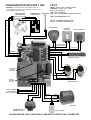
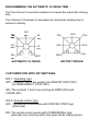
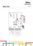
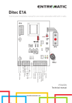
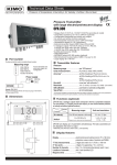
MIRA
ELECTRONIC CONTROL BOARD SUITABLE FOR
AUTOMATIONS WITH 1 MOTOR
WITH INPUTS FOR LIMIT SWITCHES
INSTALLATION AND USER MANUAL
Product designed and manufactured in Italy
LEDS
CONFIGURATION WITH DIP 1 OFF
WARNING!!! : CHECK ALWAYS THE CONNECTION TYPE
(N.C) NORMALLY CLOSED, (N.O.) NORMALLY OPEN AND
THE CORRESPONDING WIRING
MAGNETICAL
LIMITSWITCH
MECHANICAL
LIMITSWITCH
AP/PP : OPEN OR STEP BY STEP
CH/STOP : CLOSE OR STOP
FTC : PHOTOCELLS
COS : SAFETY EDGE
ANTENNA L24 : 24V ACCESSORIES POWER SUPPLY
LPR : PROGRAMMING LED
B
L
A
C
K
LFC A : OPENING LIMITSWITCH
LFC C : CLOSING LIMITSWITCH
KEYSWITCH
R
E
D
START
BUTTON
STOP BUTTON
GROUND
ANTENNA
B
R
O
W
N
RADIO RECEIVER
1
2
3
4
5
6
7
8
LPR
PPR
COMMON
OPENING (N.C.)
CLOSING (N.C.)
9
10 LFCA
11
LFCC
DIP
AP/PP
CH/STOP
FTC
COS
L24
SWITCH OR/AND
KEYSWITCH(N.O.)
STOP (N.C.)
COMMON
PHOTOCELLS (N.C.)
SAFETY EDGE (N.C.)
COMMON
24Vac
24Vac
SAFETY EDGE
TX
RX
5
AUTOMATIC
CLOSING
SETTING
1
4
3
3
1
MOTOR
TORQUE
SETTING
FUSE
4A
PHOTOCELLS
12 13 14 15 16 17 18 19
230V - MAINS
Ground wire
230V - NEUTRAL
BROWN
BLUE
BLACK
OPEN
COMMON
CLOSE
MOTOR
FLASHING LIGHT
CHARLY 230V
CAPACITOR
PLEASE BRIDGE STOP, PHOTOCELLS AND SAFETY EDGE IF NOT CONNECTED
LEDS
CONFIGURATION WITH DIP 1 ON
WARNING!!! : CHECK ALWAYS THE CONNECTION TYPE
(N.C) NORMALLY CLOSED, (N.O.) NORMALLY OPEN AND
THE CORRESPONDING WIRING
MECHANICAL
LIMITSWITCH
MAGNETICAL
LIMITSWITCH
AP/PP : OPEN OR STEP BY STEP
CH/STOP : CLOSE OR STOP
FTC : PHOTOCELLS
COS : SAFETY EDGE
ANTENNA L24 : 24V ACCESSORIES POWER SUPPLY
LPR : PROGRAMMING LED
B
L
A
C
K
LFC A : OPENING LIMITSWITCH
LFC C : CLOSING LIMITSWITCH
R
E
D
CLOSE
BUTTON
OPEN
BUTTON
GROUND
ANTENNA
B
R
O
W
N
RADIO RECEIVER
1
2
3
4
5
6
7
8
LPR
COMMON
OPENING (N.C.)
CLOSING (N.C.)
PPR
9
10 LFCA
11
LFCC
DIP
AP/PP
CH/STOP
FTC
COS
L24
OPEN (N.O.)
CLOSE(N.O.)
COMMON
PHOTOCELLS (N.C.)
SAFETY EDGE (N.C.)
COMMON
24Vac
SAFETY EDGE
24Vac
TX
RX
5
AUTOMATIC
CLOSING
SETTING
1
4
3
3
1
MOTOR
TORQUE
SETTING
FUSE
4A
PHOTOCELLS
12 13 14 15 16 17 18 19
230V - MAINS
Ground wire
230V - NEUTRAL
BROWN
BLUE
BLACK
OPEN
COMMON
CLOSE
MOTOR
FLASHING LIGHT
CHARLY 230V
CAPACITOR
PLEASE BRIDGE STOP, PHOTOCELLS AND SAFETY EDGE IF NOT CONNECTED
INSTALLATION REMARKS
The Mira-L is a simple and innovative control unit that does not require
any programming for the work timing.
Working times are set automatically when power is applied to the control
unit and after the first movements are performed.
No special actions are required for installers and end users.
The MIRA-L is the first self programming control unit.
In addition 4 switches are available to customize operations.
The input of the mains voltage is protected against voltage surges and
the power supply line of the 24V accessories does not need fuses
because we have placed a thermal protection inside the transformer.
If there is a shortcircuit on the 24V line the power LED goes off and if the
installer does not notice immediately the problem, the processor will
shutdown the control unit.
After removing the short-circuit the control unit will restart instantaneously
without damage and without replacing any fuses.
The Mira-L is designed to work with mechanical and electronic limit
switches and can not be used if there are no limit switches.
WORK TIMING PROGRAMMING:
Automatic, no action required by the installer or end user.
To restore the factory setting, position the gate on the closing limit switch,
turn power off, wait 5 seconds, then turn power on again.
PROGRAMMING REMOTE CONTROL CODES:
1. Press and release the button PPR
2. The programming LED starts flashing
3. Press the desired button on the remote control, repeat the operation
with all the remotes to store
4. Press the button PPR to exit the programming mode
Please note:
If a code sent by the remote control already exists in memory it will be
deleted.
After a few seconds the control unit will automatically exit programming.
ERASING ALL REMOTE CONTROL CODES:
To clear all the remote codes stored in memory press and hold the PPR
button until LED lights up again.
PROGRAMMING THE MOTOR TORQUE:
Turn trimmer 1 counterclockwise to increase the torque of the motor.
Turn trimmer 1 in a clockwise direction to decrease the torque of the
motor.
PROGRAMMING THE AUTOMATIC CLOSING TIME :
Turn the trimmer 2 counterclockwise to increase the automatic closing
time
Turn trimmer 2 clockwise to decrease the automatic closing time or
remove it entirely
180
sec.
210
sec.
240
sec.
120
sec.
50%
60
sec.
70%
10
sec.
85%
15%
100%
5%
OFF
AUTOMATIC CLOSING
30%
MOTOR TORQUE
CUSTOMIZATION WITH DIP SWITCHES:
DIP 1: Operating logic
OFF: contacts 1 and 2 are working as STEP-BY-STEP (NO)
and EMERGENCY STOP (NC)
ON: The contacts 1 and 2 are working as OPEN (NO) and
CLOSE (NO)
DIP 2: Remote control logic
OFF: The remote control works with STEP BY STEP logic
(start-stop)
ON: The remote control works with CONDOMINIAL logic
(executes only opening when fully open sends closing pulse)
DIP 3: Activation inversion for brake
OFF: Inversion turned off
ON: The motor reverses the sens of rotation when it intercepts the
limit switches, it working as brake
DIP 4: Direction of travel
This dip changes the motor direction of travel and the limit switches
readings without physically having to exchange the electrical
connections.
EXAMPLE:
If your sliding gate should open to the right but with the standard wiring
instead moves to the left simply reverse the position of DIP from ON to
OFF or vice versa. It is not necessary to exchange the electrical
connections.
The same principle explained in the above example also applies to doors
if the movements of opening / closing are reversed.
SHORT CIRCUIT PROTECTION
In the control unit a fuse is present to protect the mains line input (230V 4A), there are no fuses for the protection of the 24V line for accessories.
In case of a 24V line short circuit the corresponding led will be turned off
and the transformer automatic protection will safeguard the control unit
components. To restart the control unit remove the short circuit.
WARNINGS!!!
OUR COMPANY, AS MANUFACTURER, CAN NOT BE HELD RESPONSIBLE FOR DAMAGES DUE TO
WRONG OR MISSING CONNECTIONS OR DUE TO AN IMPROPER SETTING.
THE SAFETY DEVICES SHOULD BE ALWAYS INSTALLED AND KEPT IN FULL WORKING ORDER.
ONCE TERMINATED THE SYSTEM SETTING THE CONTAINER SHOULD BE PLACED BACK ON ITS
POSITION, FASTENING TIGHT ITS SCREWS.
OUR COMPANY, AS MANUFACTURER, CAN NOT BE HELD RESPONSIBLE FOR DAMAGES DUE TO
IMPROPER USE OF THE DOOR/GATE.
IT IS FORBIDDEN TO REPLACE ANY ELECTRIC, ELECTRONIC OR MECHANIC PART WITH NOT ORIGINAL
SPARE PARTS.
OUR COMPANY, HAS THE RIGHT TO MODIFY OR CHANGE THE ELECTRONIC BOARDS AND MANUALS,
WITHOUT PRIOR NOTICE.
ALWAYS REGULATE ACCURATELY THE TORQUE OF THE MOTORS. AN INCORRECT SETTING OF THE
TORQUE, MAY CAUSE DAMAGE TO PEOPLE, ANIMALS OR OBJECTS.
WARRANTY:
Devices and accessories are guaranteed for a period of 24 months after production, whose date is printed on
each item. The company will replace or repair its devices, provided that they are returned to our factory with
the warranty label in good conditions. In case of replacement of the returned items, these will remain
property of the company.
The warranty does not include damages due to any incorrect use, such as: non fulflment of the instruction
detailed for each device, maintenance and servicing carried out without the previous written consent of our
company. Moreover, warranty does not cover any damage due to wrong tension supply and any other
reason for which the manufacturer cannot be made responsible. Any device returned must be delivered to
our company with carriage paid and will be sent back with freight collect.
Warranty validity ceases if customer’s payments are not fulflled. Each device manufactured by our company
meets the european safety standards.
Our company declines all responsibility for the non-observance of the safety rules by the installers.
In order to reduce the time spent for servicing the returned items, all faulty materials which have been sent
back to us must be accompanied by the installer description of the item fault.