1
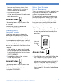
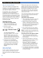
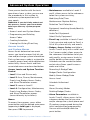
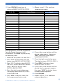
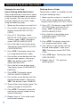
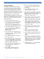
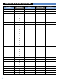
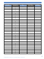
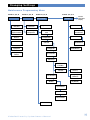
VIA-Pro Security System
Manufactured by RSIalarm
Document No. 2012 June 2007
Owners
Manual
Table of Contents
System Limitations............................................................................................................ 1
Your Privacy........................................................................................................................ 1
About Your Security System..........................................................................................2
System Components........................................................................................................2
Terms You Should Know..................................................................................................3
What Happens During an Alarm.....................................................................................3
Intrusion/Burglary Alarm................................................................................................3
Fire Alarm...........................................................................................................................3
What to do If an Alarm Occurs.......................................................................................4
Stopping an Alarm............................................................................................................4
Alarms Caused By an Intruder.......................................................................................4
Fire Alarms.........................................................................................................................4
Accidental Alarms.............................................................................................................5
Preventing Accidental Alarms.......................................................................................5
Basic Systeevm Operation..............................................................................................6
Keypad Button Functions................................................................................................6
Keyfob Button Functions.................................................................................................6
Arming Modes....................................................................................................................6
Arming the System........................................................................................................... 7
Full Arming Mode.............................................................................................................. 7
Perimeter Arming Mode.................................................................................................. 7
Arming with Protected Doors or Windows Opened...................................................8
Disarming the System......................................................................................................8
Disarming when Arriving Home.....................................................................................8
Disarming after Overnight Arming...............................................................................9
Using Your System for an Emergency..........................................................................9
Activating an Alarm in an Emergency..........................................................................9
Special Arming Modes................................................................................................... 10
Arming the System Using Special Arming Modes................................................... 10
Voice and Email Alarm Messages................................................................................ 10
Receiving Voice Alarm Messages by Phone.............................................................. 10
Receiving Alarm Messages by Email.......................................................................... 10
Advanced System Operation..........................................................................................11
Access Levels and System Menus.................................................................................11
Access Levels and System Function Control..............................................................11
Maintenance.......................................................................................................................11
Event Log............................................................................................................................11
Badges, Access Codes.....................................................................................................11
Alarm Parameters.............................................................................................................11
Changing the System Level.......................................................................................... 12
Programming and Deleting Access Codes................................................................. 12
Access Code Changes Log.............................................................................................13
Changing Access Code Alarm Arming Mode Restrictions..................................... 14
Deleting Access codes................................................................................................... 14
Creating Schedules......................................................................................................... 15
Schedule Logs............................................................................................................. 16-17
Viewing the History/Eventy Log.................................................................................. 18
Regulatory Information................................................................................................. 19
Thank you for choosing the Videofied security system.
This owner’s manual provides the necessary
information for using your system.
If you ever have any questions or concerns about
your security system, contact your installation/service
dealer. Use the space below to fill in your dealer contact
information for quick and easy reference.
Dealer name:
Phone number:
System Limitations
Having an alarm system does not
guarantee protection against burglary,
fire, or other security/safety related
conditions. All alarm systems are
subject to possible compromise or
failure to warn for several reasons,
including:
• If intruders have the technical means of bypassing or disabling
•If power to detectors is inadequate or removed.
• If smoke does not reach a smoke detector.
For example, smoke detectors cannot
detect smoke inside chimneys, walls,
roofs, or if closed doors block the path
of smoke. Smoke detectors may not
detect smoke on building levels different
from their installed location. Smoke
detectors may not warn in time when
fires are caused by smoking in bed,
explosions, improper storage of
flammables, overloaded electrical
circuits, or other hazardous conditions.
• If telephone service is interrupted
or disconnected. Telephone lines are also vulnerable to compromise by several means.
Having an alarm system may make
you eligible for reduced insurance
premiums. However, security systems
are no substitute for insurance. Security
systems cannot compensate you for
loss of life or property.
Your Privacy
RSIalarm security systems use
cameras for video verification of
alarms. It is important that you know
any cameras in your system are inactive
when the system is disarmed (off). A
camera is active only during an alarm
condition caused by activity inside the
premises when the system is armed (on).
V i d e o f i e d S e c u r i t y Sy s te m O w n e r s M a n u a l
1
About Your Security System
This provides an overview of your
security system that describes the
components, terminology, and basic
information about alarm conditions
to help you become familiar with
your system.
We recommend that you read this
section before attempting to use your
system. Even if you have previous
experience with security systems, this
information is valuable since all
systems vary in their operation.
System Components
This is a wireless security system.
There are no wiring connections
between any components and the
control panel. The only required wiring
is for telephone line connections to the
control panel. The following describes
the individual components that may
be a part of your system:
Motion
Sensor
0 lux
digital
camera
Motion-activated Cameras—detect
persons moving within their field of
view, activating a built-in camera that
captures a 10-second digital video clip
for verification. Some models have a
pet-immunity feature that allows roaming
pets weighing up to 40 lbs./18 kg.
2
Control Panel—monitors all components in the system, activates sirens,
and notifies you and the central
monitoring station of alarms.
Keypads—wall-mounted
devices that allow complete
operation of your system
and provide system status
information on a built-in
display.
Keyfobs—portable devices
that allow limited or basic
operation of your system.
Sirens—alert you
inside and outside to
emergency situations.
Outdoor sirens also
include a strobe light to help responding
authorities find your location.
Door Contacts—
detect when protected
doors and/or windows
are opened or closed.
Environmental
Detectors—typically
smoke detectors that
activate when smoke is
detected
Terms You Should Knowsection
The following describes terms to
help you understand and operate
your security system.
• Access Codes—4- to 6-digit numbers that allow only authorized persons to operate the system.
• Arm—to turn on intrusion/burglary protection so that the control panel responds by sounding an alarm, if necessary.
• Disarm—to turn off intrusion/burglary
protection.
• Entry/Exit Delays—allow authorized persons time to enter (entry delay) or leave (exit delay) the armed premises through a designated delay door, without causing an alarm.
• Instant—detectors in the system programmed with no entry/exit delay that trigger an immediate alarm when activated while the system is armed.
• Panic Alarm—an alarm that you activate from a Keypad or Keyfob
in case of an emergency.
• Arming Modes—determine how
much intrusion/burglary protection
is turned on.
What Happens During An Alarm
The following describes how your
system responds to intrusion/burglary
and fire alarms.
Intrusion/Burglary Alarm
• The control panel activates interior and exterior sirens.
•Keypads display the detector(s)
in alarm.
•The control panel reports the alarm
to the central monitoring station, identifying the detector(s) that triggered the alarm. If programmed by your installer, you also receive voice notification by phone (at your office, cabin, on your cellular, etc.) and/or by an Email message.
•If the alarm was caused by a motion-
activated camera, the control panel includes a 10-second digital video clip in its report for alarm verification. If programmed by your installer, you also receive the video clip on your cellularphone.
•The central monitoring station operator contacts the proper
authorities so they can be dispatched to the premises.
Fire Alarm
•The control panel activates interior and exterior sirens.
•Keypads display the detector(s)
in alarm.
•The control panel reports the alarm
to the central monitoring station, identifying the detector(s) that triggered the alarm. If programmed by your installer, you also receive voice notification by phone (at your office, cabin, on your cellular, etc.) and/or by an Email message.
•The central monitoring station operator contacts the proper authori
ties so they can be dispatched to the premises.
V i d e o f i e d S e c u r i t y Sy s te m O w n e r s M a n u a l
3
What Happens During An Alarm
What to do If an Alarm Occurs
•If you arrive home and hear sirens
The first thing most people want to
know about their security system is how
to turn off the sirens or stop an alarm.
Alarms can occur automatically,
intentionally, or accidently whether the
system is armed or disarmed.
or see signs of forced entry (broken windows, damaged doors, etc.), do not enter the premises. An intruder may be inside. Call for help from a cell phone or other location and wait for authorities to arrive.
•If you enter the premises and
Intrusion/burglary alarms and fire
alarms require different action, depending on the circumstances. This section
provides information to help prepare
you to take the correct action if an
alarm occurs.
Stopping an Alarm
Fire alarms require being prepared
ahead of time by planning your escape
routes from each room in your home
and practicing evacuating the building.
Regardless of who or what caused
the alarm, this procedure silences
system sirens.
1. At the nearest Keypad, enter
Access Code +
OR:
YES
On any Keyfob, press the OFF button.
1. Interior sirens sound a long beep, indicating the system is disarmed. The display shows INTRUSION DETECTED.
2.Press YES. The display shows
the device that was tripped, causing the alarm.
3. Press YES. The display shows the date, time, and level.
Alarms Caused By an Intruder
The sound of sirens may or may not
scare off intruders. Also, the sirens in
your system are programmed to stop
after a specific time setting expires.
Use the following guidelines to
determine what to do.
4
discover there was an alarm, leave immediately. Call for help from a cell phone or other location and wait for authorities to arrive.
Fire Alarms
• Plan escape routes. Two escape routes per room are recommended.
•Use a different escape route if closed doors feel warm or hot to the touch.
• Emphasize that everyone must escape as quickly as possible. DO NOT gather any belongings to take with you, which could prevent you from getting out safely.
• Crawl and hold your breath as
much as possible to help reduce smoke inhalation during your escape.
• Meet at a designated outdoor location.
•Emphasize that no one should
re-enter the premises if a fire exists.
Warning! Do not re-enter the building if sirens stop.
The sirens in your system are programmed to stop
after a specific time setting expires. This does not
mean it is safe to re-enter the building. Only fire
department personnel can determine when it is safe to
re-enter the building.
Accidental Alarms
Preventing Accidental Alarms
Owning a security system means
changing some habits to avoid causing
accidental alarms. It can be a startling
experience not only from the alarm
itself, but also if local ordinances mandate
that you are fined for such an event.
The following guidelines describe good
habits to help prevent accidental alarms.
Most accidental alarms occur when
leaving after arming, or entering the
armed premises when returning home.
For example, you may arm the system
and realize you forgot something.
Instead of disarming the system, you
automatically go get the item you
forgot, only to walk in front of a motion
detector and cause an alarm. Other
accidental alarm causes include:
•Pay close attention to siren status •Exit and enter the premises
only through doors programmed
with delays.
•Leaving after the exit delay expires.
•Make sure pets are not roaming
•Not disarming the system before the freely in areas where they may set
off an alarm.
entry delay time expires.
•Exiting or entering through a door without a delay.
•Make sure each system user is familiar with the location of all system components and understands how they operate.
beeps, indicator lights, and messages on keypad displays which show the current status of your system.
•Close all doors and windows before arming the system.
•Make sure to have all necessary belongings so you can exit immedi-
ately after arming the system.
•Disarm your system immediately
upon entering the armed premises.
V i d e o f i e d S e c u r i t y Sy s te m O w n e r s M a n u a l
5
Basic System Operation
Keypads and Keyfobs are used to
control your system. Keypads allow
complete system control while
Keyfobs allow limited or basic system
control. The following describes the
Keypad and Keyfob button functions.
Note: The keypad display goes blank after
30 seconds of no activity. Press any key to
wake it up, then enter your code, etc.
Keypad Button Functions
1 - 9, 0—use for entering access
codes and other numerical
information.
1
1—arms system to Special Mode 1.
2
2—arms system to Special Mode 2.
House—arms perimeter
protection only.
CLR
1
2
1
2
ABC
4
Left Arrow—move backward
through menus/choices.
5
CLR—clear numerical/text entries.
3
CLR
6
ESC
NO
DEF
GHI
JKL
MNO
7
8
9
PQRS
TUV
WXYZ
M
0
@
m
ESC/NO—back out of a menu
or skip to the next one.
YES
Right Arrow—move forward
through menus/choices.
M
ESC
NO
YES
YES—proceed with the
prompted action or accept
the displayed entry/setting.
@
m
M/m—change between uppercase and
lowercase characters for text entries.
@—use for special text
and punctuation entries.
Keyfob Button Functions
ON
OFF
ON—Full arming
OFF—disarms system.
1
1
1—arms system to Special Mode 1 or
audible panic even if Special Mode 1
is not programmed.
Arming Modes
Arming modes let you select how much
of your system is turned on or armed.
There are two basic arming modes:
• Full Arming—arms all perimeter
and interior intrusion/ burglary protection areas.
6
2
2
2—arms system to Special Mode 2
or silent panic.
Note: to activate panic alarms
press and hold button 1 or 2.
• Perimeter Arming—arms only
perimeter intrusion/burglary
protection areas to allow normal activity inside the premises.
• Special Modes 1, 2—arm specific
areas based on programming by your installer.
Arming the System
You can arm your system whether you
are leaving or staying on the premises.
Choose from the following procedures.
Full Arming Mode
Arming to this mode provides
protection for all perimeter and
interior areas. Use this procedure
when leaving the premises.
1. Close all protected doors
and windows.
2 .Gather any belongings you want
to take with you.
3.Arm the system:
At the Keypad nearest an entry/exit
delay door, enter:
Access Code +
YES
If arming from a Keyfob,
press the ON button.
The Keypad responds by displaying
ARMING THE SYSTEM, the LED flashes
once every two seconds, and a beep
sounds every second indicating the exit
delay has started and the system is
arming.
4.Immediately leave through the
entry/exit delay door.
Note: If any detection sensors are activated
during the exit delay, the system momentarily stops the arming sequence.
The Keypad display shows DETECTION,
identifies the activated sensor(s), then
changes to ESC = REJECT EQUIP, YES = TRY
AGAIN.
If you choose to try again, you must first
close the identified sensor(s) before pressing
YES.
If you choose to reject(bypass), this means
the identified sensor(s) will not trigger an
alarm during this arming period.
If you do not make a choice after three
minutes, the system automatically bypasses
the identified sensor(s) for this arming
period and arms the rest of the system.
Perimeter Arming Mode
Arming to this mode provides
protection for the perimeter (doors
and windows) only. This allows persons
to stay inside the premises and move
freely without triggering motion
detectors. You can use this mode
whether you are leaving or staying
on the premises. This mode works
well for overnight sleeping periods.
1. Close all protected doors
and windows.
2.Arm the system:
At the Keypad nearest an entry/exit
delay door, enter:
+ Access Code +
YES
The Keypad responds by displaying
ARMING THE SYSTEM, the LED flashes
once every two seconds, and a beepsounds every second indicating the
exit delay has started and the system
is arming.
3. If leaving, do so immediately through
an entry/exit delay door.
If staying, notice the Keypad LED
flashes once every two seconds and the
display shows SYSTEM ARMED.
Caution! To avoid an accidental alarm
when arming to this mode and staying inside,
remember to disarm the system before
opening any doors and/or windows.
Note: Keyfobs do not have perimeter arming
modes
V i d e o f i e d S e c u r i t y Sy s te m O w n e r s M a n u a l
7
Basic System Operation
Note: If any door contacts are activated
during the exit delay, the system momentarily
stops the arming sequence.
The Keypad display shows DETECTION,
identifies the activated devices(s), then
changes to ESC = REJECT EQUIP,
YES = TRY AGAIN.
If you choose to try again, you must
first close the identified device(s) before
pressing YES.
If you choose to reject (bypass), this means
the identified devices(s) will not trigger an
alarm during this arming period.
If you do not make a choice after three
minutes, the system automatically arms the
system.
Arming with Protected
Doors or Windows Opened
You can arm your system and still leave
some protected doors or windows open.
For example, you may want a window
open during the night and still arm the
remaining perimeter zones. Or, you may
want a window open during the day
while you are gone and still arm the
remaining perimeter and interior areas.
Note: Arming the system in this manner
means that any protected doors or windows
left open are excluded from the current
arming period and will not trigger an alarm.
1. Open the desired protected doors and/or windows.
2.Arm the system: If leaving, at the Keypad nearest an entry/exit delay door,enter:
YES
If staying, enter:
+ Access Code +
8
3.The display then shows DETECTION, identifies the activated device(s), then changes to ESC = REJECT EQUIP, YES = TRY AGAIN.
4.Press ESC/NO. The system
continues arming, bypassing the identified zones. If leaving, do so immediately through an entry/exit delay door.
Disarming the System
The system must be disarmed upon
entering the armed premises or when
waking up in the morning before
opening any door (such as getting the
morning paper) or window.
When disarming from a Keypad, the
system requires an access code so that
only an authorized system user can
disarm. If you forget your access code
or an unauthorized person tries to
disarm the system, the Keypad stops
accepting access code entries after
three incorrect codes. Thereafter, only
one access code attempt per minute is
allowed until a valid code is entered.
Disarming when Arriving Home
Entering the armed premises must be
done through a designated entry/exit
delay door. This triggers the entry delay
time and keypad and interior siren
beeps, as a reminder to disarm the
system to avoid an alarm.
Access Code +
The Keypad responds by displaying ARMING THE SYSTEM, the LED flashes once every two seconds, and a beep sounds every second indicating the exit delay has started and the system is arming.
YES
1. Enter the armed premises through
a designated entry/exit delay door. Keypads and interior sirens start beeping, indicating the system is armed and must be disarmed.
2.Disarm the system:
At the Keypad nearest the entry/exit delay door, enter:
Access Code +
YES
If disarming from a Keyfob, press the
OFF button.
The Keypad shows the date/time
display and DISARMED.
Disarming after
Overnight Arming
Since there are no entry beeps to
remind you in the morning that the
system is armed, waking up inside the
armed premises requires immediate
disarming before opening any protected door or window. As mentioned earlier,
the Keypad LED flashes once every two
seconds as a reminder that the system
is armed.
1. After waking up, press any Keypad button (except the red panic button) to activate the display, which shows SYSTEM ARMED.
2.Immediately disarm the system:
At the Keypad, enter:
Access Code +
YES
If disarming from a Keyfob, press the
OFF button.
The Keypad shows the date/time
display and DISARMED.
Using Your System
for an Emergency
You can manually activate a panic alarm
anytime the need occurs, whether the
system is armed or disarmed.
For example, if someone experiences a
medical condition or an injury, it is best
to activate the alarm and get trained
professional help to your location. You
can even have your installation dealer
set this up for a specific use based on
your personal needs.
Activating an Alarm in an Emergency
•Press and hold the red panic button on any Keypad for two seconds, then release it.
1
Keypad
Panic
Button
1
4
GHI
7
2
2
ABC
5
JKL
8
3
CLR
6
ESC
NO
DEF
MNO
9
PQRS
TUV
WXYZ
M
0
@
m
YES
Access Code +
YES
•On a Keyfob, press and hold either the
1 or 2 button for five seconds, then release them. If button 1 is pushed the interior and exterior sirens activate. If button 2 is pushed the silent panic is not displayed on the keypad and the control panel sends an emergency alarm report to the central monitoring station.
V i d e o f i e d S e c u r i t y Sy s te m O w n e r s M a n u a l
9
Basic System Operation
Special Arming Modes
The 1 and 2 buttons on Keypads and
Keyfobs can be programmed by your
installer to arm the system according to
your specific needs or lifestyle.
For example, your system may have
divided your home into different
protection areas. Instead of using the
full and perimeter arming modes, these
buttons can be set up to arm a specific
area or combination of areas while still
giving you access to other areas that
will not be armed.
Arming the System
Using Special Arming Modes
1. Close all protected doors and windows in the affected areas.
2.Arm the system:
At any Keypad, enter:
1
or 2
This section describes how you receive
alarm messages by phone and Email.
Receiving Voice
Alarm Messages by Phone
1. The system goes into alarm and calls the programmed phone number.
2.When you pick up or answer the phone, a computer generated voice identifies the date/time of the alarm, the type of alarm, and the device that caused the alarm.
3.Press the # button on your phone
to verify you received the message.
+ Access Code +
Note: If you don’t press the # button, the
YES
The Keypad responds by
displaying ARMING THE SYSTEM, the LED flashes once every two seconds, and a beep sounds every second indicating the exit delay has started and the system is arming.
3.If leaving, do so immediately throughan entry/exit delay door.
If staying, notice the Keypad LED flashes once every two seconds
and the display shows SYSTEM ARMED.
Voice and Email
Alarm Messages
If your system is armed and an alarm
occurs while you are away, you can
receive the alarm message by phone or
Email.
10
Phone messages are in the form of a
digital voice that identify the date/time
of the alarm, the type of alarm, and the
device that caused the alarm. Email
messages contain this same information and may also include a video file
that you can view.
system continues reporting the voice alarm
message at regular intervals.
Receiving Alarm Messages by Email
1. The system goes into alarm and sends an Email to the programmed Email address.
2.Open the attachment in the Email message (ASCII file format) using a word/text processor such as Microsoft® Word® or Notepad®.
The file identifies the date/time of the alarm, the type of alarm, and
the device that caused the alarm.
3.If a video file attachment is included, simply double-click on this attachment to view the video.
Advanced System Operation
Once you are familiar with the basic
operation of your system, you can use
the procedures in this section to
customize system operation to fit
your needs.
WARNING: If you don’t fully understand
this process, contact your alarm dealer
before you alter any system programming.
•Access Levels and System Menus
•Programming and Deleting
•Maintenance—available in Levels 2 and 3, allows access to the submenus below for system servicing.
Modifying Date/Time
Maintenance—Replace Battery
Detection Test—Detectors
Equipment Localizing (locate/identify detectors)
Audio Test Equipment
Access Codes
Select Faulty Equipment
•Creating Schedules
•Event Log—available in Levels 2 and 3, lets you view and send via Email, a list of all system activity and events.
•Viewing the History/Event Log
Access Levels
and System Menus
Access levels determine how much
access you have to menus that let you
view and/or change system information.
Each system access code is assigned to
a specific access level, which determines
accessibility. Access levels and their
associated menus are described below.
Access Levels and System Function
Control
•Level 1—Arm and Disarm only.
•Level 2—Arm, Disarm, Maintenance, Events Log, Badges Access Codes, and Alarm Parameters menus.
•Badges, Access Codes—available in Levels 2 and 3 (only with a valid Level 2 or 3 access code), allows access to the submenus listed below to let you add, modify, assign access levels to, and/or delete system access codes. Schedules can be created to define
certain days/times specific access codes are active.
Recording A Badge/Code
Badges/Codes Configuration
Modify Name—Badge/Code
Access Level
Schedule Authorized
•Level 3—same as Level 2.
Areas
•Level 4—Configuration, Maintenance, Alarm (Arming) Modes
Events Log, Badges Access Codes, and Alarm Parameters menus (accessible only by installers).
Deleting Badges/Codes
Menus
To access these menus, press either
arrow button until the desired main menu
(appearing in bold type) is displayed,
then press YES to proceed.
•Alarm Parameters—available in
Levels 2 and 3, allows access to the submenus below that let you view and/or change the system phone and IP numbers programmed during the initial configuration/programming. You can also enable/disable the
panic button.
V i d e o f i e d S e c u r i t y Sy s te m O w n e r s M a n u a l
11
Advanced System Operation
Changing the System Level
When changing the system level, you
are required to enter an access code
when increasing the level. No code is
required when changing to a lower level.
• Level 1—Arm and Disarm only.
•Level 2—Arm, Disarm, Maintenance, Events Log, Badges. Access Codes, and Alarm Parameters menus.
•Level 3—same as Level 2.
•Level 4—Configuration, Maintenance, 1. With the display showing the date/
time and current level, press the right Events Log, Badges Access Codes, arrow button once. The display shows and Alarm Parameters menus.
ACCESS LEVEL (current level 1 - 4).
1. Make sure the system is in
2.Press YES. The display shows a
colon (:) between LEVEL and the number.
3.Press either arrow button until the desired level number appears, then press YES. If increasing the level, the display shows BADGE OR CODE.
4.Enter the appropriate access code (one assigned to the level selected in step 3), then press YES. The display shows the new level.
Programming and
Deleting Access Codes
Your security system allows you to
program up to 20 different access codes.
This gives each individual system user
their own access code with specific
abilities or restrictions.
Just as important, access codes can
and should be deleted when they are
no longer needed. This helps prevent
unauthorized system access and also
helps you maintain the integrity of
your system.
Programming Access Codes
Use the table on the next page to record
and keep track of system access codes.
Access codes must be 4 to 6 digits,
given a name, and assigned to an access
level that determines their abilities or
restrictions. The differences between
access levels are described below.
12
Level 2 or 3.
2.Press either arrow button until
the display shows BADGES ACCESS CODES.
3.Press YES. The display shows BADGE OR CODE. Enter a Level 2 or 3 access code + YES. The display shows ENTER A BADGE/CODE.
4.Press YES. The display shows BADGE OR CODE.
5.Enter the desired new code + YES. The display shows CONFIRM THE CODE.
6. Re-enter the new code + YES. The display shows CODE NAME:
7. Enter the desired user name + YES. The display shows [NAME] RECORD
ED, then returns to RECORD
ING A BADGE/CODE.
8.Press the right arrow button once. The display shows BADGES/CODES CONFIGURATION.
9.Press YES. The display shows MODIF NAME BADGE CODE.
10.Press the right arrow button once. The display shows ACCESS LEVEL 3.
11.Press YES. The display shows ACCESS LEVEL LEVEL: 3.
12.Press either arrow button until the desired level is displayed,then press YES. The display shows the new
level assignment.
13.Press ESC/NO three times to return to BADGES ACCESS CODES.
Code No
14.Repeat steps 2 - 12 to continue
programming codes.
Code Name
Changing Access Level Assignments
You can change the access level
assignments as needed anytime, using
the following steps.
Level
1. Make sure the system is in Level 2 or 3.
6 . Press either arrow button until the desired code appears, then press YES. The display shows MODIF NAME BADGE/CODE.
2.Press either arrow button until the display shows BADGES ACCESS CODES.
7. Press the right arrow button once. The display shows ACCESS LEVEL 3.
3. Press YES. The display shows BADGE OR CODE. Enter a Level 2 or 3 access code + YES. The display shows ENTER A BADGE/CODE.
8. Press YES. The display shows ACCESS LEVEL LEVEL:3.
4.Press the right arrow button once. The display shows BADGES/CODES CONFIGURATION.
5.Press YES. The display shows the first programmed access code.
9. Press either arrow button until the desired level assignment appears, then press YES. The display shows the new level assignment.
10.Press ESC/NO.
11. Repeat steps 5 - 9 for additional code configurations.
V i d e o f i e d S e c u r i t y Sy s te m O w n e r s M a n u a l
13
Advanced System Operation
Changing Access Code
Alarm Arming Mode Restrictions
After programming a new access code,
all alarm (arming) modes are available
using the code. You can restrict alarm
(arming) modes for any access code,
using the following steps.
1. Make sure the system is in Level 2 or 3.
2. Press either arrow button until the display shows BADGES ACCESS CODES.
3. Press YES. The display shows BADGE OR CODE. Enter a Level 2 or 3 access code + YES. The display
shows ENTER A BADGE/CODE.
4.Press the right arrow button once. The display shows BADGES/CODES CONFIGURATION.
5. Press YES. The display shows the first programmed access code.
6. Press either arrow button until the desired code appears, then press YES. The display shows MODIF NAME BADGE/CODE.
7. Press the left arrow button once.
The display shows ALARM MODES ENABLED.
8. Press YES. The display shows SPECIAL MODE 1 ENABLED.
9. Press either arrow button until the desired mode appears, then press YES. The display shows ENABLED:
10. Press either arrow button once. The display changes to DISABLED.
11. Press YES. The display shows the new alarm (arming) mode setting without the colon.
12.Repeat steps 6 - 11 for other code restriction changes.
14
Deleting Access Codes
Delete access codes as needed anytime,
using the following steps.
1. Make sure the system is in Level 2 or 3.
2.Press either arrow button until the display shows BADGES ACCESS CODES.
3.Press YES. The display shows BADGE OR CODE. Enter your level 2 or 3 code + YES. The display shows ENTER A BADGE/CODE.
4. Press the left arrow button once.
The display shows DELETING BADGES/CODES.
5. Press YES. The display shows the first programmed access code.
6. Press either arrow button until the desired code appears, then press YES. The display shows DELETING CODE.
7. Press YES again. The display shows CODE DELETED.
8.Repeat steps 6 - 7 to continue deleting codes.
Creating Schedules
Schedules allow you to control when
a specific access code can be used to
arm and disarm the system. A schedule
consists of a day, beginning time, and
ending time that the specific access code
can be used. Up to five schedules can be
programmed for each access code.
Use the tables on page 16-17 to fill in the
necessary schedule information for each
code. Enter this information using the
procedure below.
1. Set the system to Level 2 or 3.
2.Press the left or right arrow button until the display shows BADGES ACCESS CODES, then press YES.
The display shows BADGE OR CODE.
9. Press the right arrow button once.
The display shows ENTER A NEW SCHEDULE.
10. Press YES. The display shows
BEGIN SCHEDUL 1 Mon.
11. Press either arrow button until the desired weekday appears, then press YES. The display shows BEGIN SCHEDUL 1 Day= 00:00.
12. Press either arrow button until the desired hour appears, then press YES. The display does not change.
13. Press either arrow button until
the desired minutes appear, then press YES. The display shows END SCHEDUL 1 MON.
14. Press either arrow button until the desired day appears, then press YES.
3.Enter the appropriate Level 2 or 3 access code, then press YES. The display shows ENTER A
BADGE/CODE
15. Press YES. The display shows
END SCHEDUL 1 Day= 00:00.
4.Press the right arrow button once. The display shows BADGES/CODES CONFIGURATION.
16. Press either arrow button until the desired hour appears, then press YES.
5.Press YES. The display shows the first access code.
17. Press either arrow button until the desired minutes appear, then press YES. The display shows SCHEDULE ENTERED!, then returns to ENTER A NEW SCHEDULE.
6. Press the left or right arrow button until the desired code is displayed, then press YES. The display shows MODIF NAME BADGE/CODE.
7. Press the right arrow button twice. The display shows SCHEDULE AUTHORIZED.
18. Repeat steps 10 - 17 for additional schedule programming.
8. Press YES. The display shows SELECT/MODIFY SCHEDULES.
V i d e o f i e d S e c u r i t y Sy s te m O w n e r s M a n u a l
15
Advanced System Operation
Code No.
Schedule No.
1
2
3
4
5
1
2
3
4
5
1
2
3
4
5
1
2
3
4
5
1
2
3
4
5
1
2
3
4
5
16
Day
Start Time
End Time
Code No.
Schedule No.
Day
Start Time
End Time
1
2
3
4
5
1
2
3
4
5
1
2
3
4
5
1
2
3
4
5
1
2
3
4
5
1
2
3
4
5
V i d e o f i e d S e c u r i t y Sy s te m O w n e r s M a n u a l
17
Advanced System Operation
Events are any system activity such
as arming, disarming, alarms, access
codes entered, and system programming changes. The control panel uses
built-in memory to record each system
event and the date/timeit occured. This
log cannot be cleared or erased and
accumulates events for up to a full year.
As additional events occur, the control
panel automatically deletes the oldest
event. This ensures an accurate one
year history.
You can view the contents of the
history/event log using a system
Keypad or by instructing the system
to send the complete event log as
an Email.
Viewing by Keypad
This method lets you view the most
recent events.
1. Set the system to Level 2 or 3.
2. Press either arrow button until the display shows EVENTS LOG.
3. Press Yes. The display shows
SELECT LAST EVENTS.
4. Press Yes. The last or most recent event is displayed.
5. Press the left arrow button to view previous events.
6. When finished, simply stop pressing buttons. The display returns to the date/time and current status, then goes blank to conserve battery power.
18
Sending History/Log
File by Email
This method lets you send a complete
history/log file to a desired Email
address for viewing. The Email includes
an attachment (in ASCII file format)
that can be opened using a word/text
processor such as Microsoft® Word®
or Notepad®
Contact your alarm dealer
for details.
Changing Settings
Maintenance Programming Menu
Levels 1 , 2 , 3 , 4
Maintenance
Levels 1 , 2 , 3 , 4
Levels 1 , 2 , 3 , 4
Levels 1 , 2 , 3 , 4
Events Log
Badges
Access Codes
Programmable
Features
Modify
Date/Time
Select
Last Events
Maintenance
Replace Battery
Send Log
File By Email
Badge or Code
Alarm Calls
Enter A Badge/
Code
Functional Test
Devices
Badge/Code
Configuration
Device Locating
Code List
Audio Test
Equipment
Modify Name
Badge/Code
Display Faulty
Devices
Access Level
Back To
Date/Time
Display
Alarm
Transmission
Videomail Alarm
Email Address
Panic Button
Enable/Disable
Schedule
Authorized
Select/Modify
Schedules
Enter A New
Schedule
Exit Delay
( 45 sec )
Zones Disarmed
Delay Beeps
( Allowed )
Alarm Modes
Allowed
Siren Panel
( By Default )
Special Mode 1
Special Mode 2
External Mode
External Mode
V i d e o f i e d S e c u r i t y Sy s te m O w n e r s M a n u a l
19
Changing Settings
Maintenance —
available in Levels 2, 3, and 4
This menu allows access for system
servicing.
• Modifying Date/Time
• Maintenance Replace Battery
• Functional Test Devices
• Device Locating (identify/
locate detectors)
•Audio Test Equipment
•Display Faulty Devices
Events Log —
available in Levels 2, 3, and 4
This menu lets you view and send via
Email, a list of all system activity
and events.
Badges, Access Codes —
available in Levels 2, 3, and 4 (only
with a valid Level 2, 3, or 4 access code)
This menu and the submenus listed
below let you add, modify, assign access
levels to, and/or delete system access
codes. Schedules can also be created
and assigned to codes
as needed.
•Recording A Badge/Code
•Badges/Codes Configuration
Modify Name Badge/Code
Access Level
Schedule Authorized Areas
Alarm (Arming) Modes
•Deleting Badges/Codes
20
Regulatory Information
FCC Part 15 Information to the User Changes or modifications
not expressly approved by RSIalarm, Inc. can void the user’s
authority to operate the equipment.
FCC Part 15 Class B This equipment has been tested and
found to comply with the limits for a Class B digital device,
pursuant to part 15 of the FCC Rules. These limits are designed
to provide reasonavble protection against interference in a
residential installation.
This equipment generates, uses, and can radiate radio
frequency energy and, if not installed and used in accordance
with the instructions, may cause harmful interference to radio
communications. However, there is no guarantee that interference will not occur in a particular installation.
If this equipment does cause harmful interference to radio or
television reception, which can be determined by turning the
equipment off and on, the user is encouraged to try to correct
the interference by one or more of the following measures:
• Reorient or relocate the receiving antenna.
•Increase the separation between the equipment and
the receiver.
• Connect the affected equipment and the panel receiver to separate AC power outlets, on different branch circuits.
• Consult the dealer or an experienced radio/TV technician
for help.
ACTA Part 68 This equipment complies with Part 68 of
the FCC Rules and the requirements adopted by the ACTA.
Located on this equipment is a labe l that contains, among
other information, the registration number and the ringer
equivalence number (REN) for this equipment. If requested,
this information must be provided to the telephone company.
The REN for the panel is 3.6”.
Registration No. US:
The REN is used to determine the maximum number of
devices that may be connected to your telephone line.
Excessive RENs on a telephone line may result in devices
not ringing in response to an incoming call. In most areas,
the sum of all device RENs should not exceed five (5.0). To be
certain of the number of devices that may be connected to a
line, as determined by the total RENs, contact the local telephone company. For products approved after July 23, 2001,
the REN for this product is part of the product identifier that
has the format US:AAAEQ##TXXXX. The digits represented by
## are the REN without adecimal point (e.g. 02 is a REN of 0.2).
For earlier products, the REN is separately shown on the label.
A plug and a jack used to connect this equipment to the premises wiring and telephone network must comply with the applicable FCC Part 68 Rules and requirements as adopted by ACTA.
A compliant telephone cord and modular plug is provided with
this product. It is designed to be connected to a compliant
modular jack. See the Installation Manual for details.
line and place a call in an emergency situation. It must be
able to do this even if other equipment (telephone, answering
machine, computer modem, etc.) already has the telephone
line in use. To do so, alarm dialing equipment must be connected to a properly installed RJ31X jack that is electrically
in series and ahead of all other equipment connected to the
same telephone line. Proper installation is depicted in the
following diagram. If you have any questions concerning these
instructions, consult with your local telephone company or
a qualified installer about installing a RJ31X jack and alarm
dialing equipment for you.
If this equipment causes harm to the telephone network, the
telephone company may temporarily disconnect your service.
If possible, you will be notifiedin advance. When advance notice
is not practical, you will be notified as soon as possible.
The telephone company may make changes in its facilities,
equipment, operations, or procedures that could affect the
operation of the equipment. The telephone company may ask
you to disconnect the equipment from the network until the
problem hasbeen corrected, or you are sure that the
equipment isnot malfunctioning.
This equipment may not be used on coin service provided by
the telephone company. Connection to party lines is subject
to state tariffs.
This device complies with Part 15 of the FCC Rules. Operation
is subject to the following two conditions: (1) this device
may not cause harmful interference, and (2) this device must
accept any interference received, including interference that
may cause undesired operation.
RF Exposure Warning :
During operation, the user has to keep a minimum separation
distance of 20 cm with the RF devices.
Le présent matériel est conforme aux spécifications
techniques applicables
d’Industrie Canada.
L’utilisation de ce dispositif est autorisée seulement aux
conditions suivantes : (1) il ne doit pas produire de brouillage
et (2) l’utilisateur du dispositif doit être prêt à accepter tout
brouillage radioélectrique reçu, même si ce brouillage est
susceptible de compromettre le fonctionnement du dispositif.
L’indice d’équivalence de la sonnerie (IES) sert à indiquer le
nombre maximal de terminaux qui peuvent être raccordés à une
interface téléphonique. La terminaison d’une interface peut
consister en une combinaison quelconque de dispositifs, à la
seule condition que la somme d’indices d’équivalence de
la sonnerie de tous les dispositifs n’excède pas 5. L’IES
de la centrale d’alarme est de 3.6
Alarm dialing equipment must be able to seize the telephone
V i d e o f i e d S e c u r i t y Sy s te m O w n e r s M a n u a l
21