1
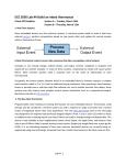
532-Q Laser
User Manual
Rheine, 27.02.2008
Version 1.1
IMPEX Hightech GmbH
Hovesaatstr. 6
48432 Rheine
Germany
Phone: +49(0)5971 981 650
FAX: +49(0)5971 981 659
532-Q Laser OEM Product Line / User’s Manual
•
When the product is received, the shipping container and its content should be
inspected for any damage incurred during shipping. In case of damage, please inform
IMPEX – HighTech immediately!
•
If any failure occurs, please contact IMPEX – HighTech immediately! Do not open
the modules! They do not contain any user serviceable parts!
•
Read this manual carefully before starting up the laser!
•
Before connecting or disconnecting any cables, switch off the laser diode driver main
power switch!
•
Always wear suitable laser goggles to protect your eyes!
1
532-Q Laser OEM Product Line / User’s Manual
Table of contents
1
USER SAFETY............................................................................................................................................ 3
1.1
1.2
1.3
1.4
2
THE 532-Q LASER ..................................................................................................................................... 6
2.1
2.2
2.3
2.4
3.
REMOVING THE COVER ....................................................................................................................... 3
LASER SAFETY WARNINGS ................................................................................................................. 3
SERVICING ........................................................................................................................................... 5
INITIAL ACTIVATION .......................................................................................................................... 5
PACKAGING ......................................................................................................................................... 6
INTRODUCTION.................................................................................................................................... 6
THE 532-Q LASER HEAD .................................................................................................................... 7
532-Q LASER DIODE DRIVER............................................................................................................... 8
OPERATING THE 532-Q LASER .......................................................................................................... 10
3.1
3.2
3.3
3.3.1
3.3.2
3.4
INSTALLING THE 532-Q LASER......................................................................................................... 10
STANDALONE OPERATION ................................................................................................................. 10
REMOTE CONTROL OPERATION ........................................................................................................ 11
Installing the remote control software......................................................................................... 11
The remote control software ........................................................................................................ 11
TURNING THE LASER ON AND OFF..................................................................................................... 16
4.
LASER SPECIFICATIONS ..................................................................................................................... 16
5.
WARRANTY ............................................................................................................................................. 19
2
532-Q Laser OEM Product Line / User’s Manual
1 User Safety
The 532-Q Laser line is a OEM product out of the IMPEX – HighTech diode-pumped solidstate lasers. As such, it is intended only for integration into other equipment. The 532-Q Laser
does not comply with Center for Devices and Radiological Health (CDRH) standards. The
customer is responsible for CDRH certification of any system that incorporates the 532-Q
Laser, if necessary.
1.1 Removing the cover
Warning:
Do not remove the cover of the laser head. Dangerous radiation exists inside the laser head.
Do not remove the cover of the control electronics. Dangerous voltages exist inside the
control electronics.
1.2 Laser Safety Warnings
Warning:
Exposure to laser radiation may be harmful. All apertures able to emit laser light in excess of
levels considered safe are identified with appropriate labels shown later in this section. Take
extreme care when working in areas where these labels are placed.
Warning:
Always provide protective eyewear suitable for the laser’s emission wavelength. The
emission wavelength of your laser model is given on the DANGER sticker at the side of the
laser head.
Warning:
Use of controls or adjustments or performance of procedures different from those specified
herein may result in hazardous radiation exposure. The use of optical instruments with these
products will increase eye hazard.
Caution:
Lasers may be damaged by improper settings of the current or temperature controls or by
improper use of the modulation input. Check line AC voltage settings before connecting
power.
3
532-Q Laser OEM Product Line / User’s Manual
The positions of the laser safety and serial labels affixed to the laser cover of the 532-Q Laser
are illustrated in the following Figure 1.1 and Figure 1.2.
Figure 1.1 Laser head with serial label.
Figure 1.2 Laser head with safety label.
4
532-Q Laser OEM Product Line / User’s Manual
Reproduction of the laser safety labels and serial label for laser of 532-Q Laser are illustrated
in the following Figure 1.3 to 1.6.
Figure 1.3 Laser serial label.
Figure 1.5 Laser safety label B (on side of the
laser head cover near screw)
Figure 1.4 Laser safety label A.
Figure 1.6 Laser safety label C (on top of laser
head close to emitting laser aperture).
The maximum power level emitted from the 532-Q Laser and the class of the Laser is given at
the laser safety label A (see Figure 1.4). This value is for pulsed operation under CW
pumping as measured in average power mode. The emission wavelength of the 532-Q Laser
is given at the Laser safety label A.
The Figure 1.3 shows the serial number of the laser, the manufacturing date and the Model of
the Laser System. Also Impex HighTech internet address is given here to allow the customer
for easy support access via internet.
The Figure 1.5 shows the DANGER label which is located close to one of the side screws
which would be necessary to remove when someone would try to open the laser head. This is
not allowed for the user because no customer adjustable part is inside the laser head. Only
dangerous radiation can emit when opening the laser head!
The Figure 1.6 is the Laser safety label C and is located close to the laser aperture which
emits the laser beam.
1.3 Servicing
There are no user replaceable parts inside the Laser head and control electronics unit. Refer
all servicing to qualified personnel of IMPEX – HighTech.
1.4 Initial Activation
Read this manual carefully before initially operating the laser system.
5
532-Q Laser OEM Product Line / User’s Manual
2 The 532-Q Laser
2.1 Packaging
1. Laser head.
2. Laser diode driver A310.
3. Power cord.
4. Laser head 15-pin cable.
5. USB-cable.
2.2 Introduction
The 532-Q Laser consists of two self-contained units, the laser head (see section 2.3) and the
laser diode driver A310 (see section 2.4). This manual is intended to provide some more
detailed information on how to operate these devices properly.
In the case of harmonic generation the laser head consists of the following components:
1. One is the electrically driven diode laser which provides the pump radiation for the
active laser crystal.
2. Lens is used to focus the pump light into the active laser crystal.
3. Essentially the active laser crystal.
4. The nonlinear harmonic generation crystal placed after active laser crystal.
In order to operate the 532-Q Laser system the laser diode driver needs to be connected to a
power network 90~264 VAC, 47~63 Hz by power cord (included in packaging). In turn the
laser head needs to be connected to the laser diode driver by laser head cable (included in
packaging). To work in remote control operation mode the laser diode driver needs to be
connected to the PC by USB-cable (included in packaging).
The provided electrical power is converted into coherent laser radiation in the infrared (IR)
spectrum. Some of the electrical power is needed for temperature stabilization of the diode
laser and for temperature stabilization of the active laser crystal. The laser diode driver is
designed to provide all subsystems to drive and control the 532-Q Laser system, featuring:
•
•
•
•
•
•
A laser diode driver providing a very stable, low noise injection current to the laser
diode.
A laser diode driver providing pulsed injection current from adjustable offset current
base with adjustable pump pulse length and repetition rate.
A pulsed laser diode driver which can be triggered from external TTL signal.
A precision temperature controller stabilizing the active laser crystal.
A precision temperature controller stabilizing the laser diode temperature, so that the
emission pump wavelength of the laser diode stays stable in the maximum absorption
bandwidth of the active laser crystal.
A feedback loop to keep the output level at a stable level and to compensate for fast
variations of the laser diode emission intensities.
6
532-Q Laser OEM Product Line / User’s Manual
2.3 The 532-Q Laser Head
The dimensions of a laser head of the 532-Q Laser are illustrated in the following Figure 2.1.
The laser beam is emitted from the laser aperture at the front side of the laser head.
Figure 2.1 Dimensions of the 532-Q Laser head.
At the rear side of the laser head, a 15-pin male D-sub connector is located, which needs to be
connected with the Laser cable (15-pin D-sub female connector). The other side of the Laser
cable is split into two D-sub male connectors. The 9 pin connector needs to be connected to
the TC (temperature controller) plug at the rear side of the electronics panel and the 15 pin
connector needs to be connected to the LD (Laser Diode) plug at the rear side of the
electronics driver.
7
532-Q Laser OEM Product Line / User’s Manual
2.4 532-Q Laser diode driver
In the 532-Q Laser used the laser diode driver A310. For all technical and usage data, please,
see the user manual of laser diode driver. The photo of the driver is shown below on the
Figure 2.2. The dimensions of the driver are shown on the Figure 2.3.
Below the rear and the front panels of the driver are shown (Figures 2.4 and 2.5).
Figure 2.2 Photo of laser diode driver.
Figure 2.3 Dimensions of the laser diode driver.
8
532-Q Laser OEM Product Line / User’s Manual
Figure 2.4 Rear panel of the laser diode driver.
Figure 2.5 Front panel of the laser diode driver.
9
532-Q Laser OEM Product Line / User’s Manual
3. Operating the 532-Q Laser
3.1 Installing the 532-Q Laser
Before connecting any power to the laser diode driver or to the laser head make sure that the
laser head is fixed in proper position using the 6 mm diameter half-holes at the bottom plate
of the laser head. See the Figure 2.1 for exact information on the dimensions of the laser head.
Make sure that the laser aperture and so the laser beam is directed to a secure target so that no
dangerous radiation can be emitted by the laser to anyone or anything. Make sure that no
static discharge voltage will be supplied to the laser head.
It is recommended to place the laser head onto a metal ground plate to provide additional heat
sink. The thermal management inside the laser head is calculated in such way that additional
heat sink is needed at high power levels and high environmental temperatures.
The laser diode driver box does not need any additional heat sink.
Remove the safety lock from the laser head plug (which shortens the laser diode during
transport to protect from static discharge). Connect the female end of the included 15-pin
laser head cable to the laser head. The other end of the cable is split into two plugs. One of
them (with 15 pins) needs to be connected to the LD connector at the rear panel of the laser
diode driver (see Figure 2.4). The other plug (9 pins) needs to be connected to the TC
connector at the rear panel of the laser diode driver. Fix all plugs with their screws.
Connect the laser diode driver to the power network by using included power cord.
3.2 Standalone operation
Turn on the power switch located on the rear panel of the laser diode driver (see Figure 2.4).
LCD display shows COOLING status. The Power LED starts blinking indicating
temperature conditioning status. The ON button is disabled while temperatures are not in
condition.
The stabilization time depends on the temperature difference at which the system was stored
and on the PID parameters (see page 14 of this manual).
Wait until the Power LED lights permanently, LD LED starts blinking and LCD Display
shows READY ON status, indicating normal temperature condition. The ON button is
enabled. Initially driver loaded with default configuration. Use Menu to change default
configuration or to load previously saved one. For details of using Menu see Laser Diode
Driver A310 User Manual, page 9.
Now open the shutter: pull up the blue plate above the emitting aperture. The 532-Q Laser is
now ready for Laser emission, if you press the ON button.
10
532-Q Laser OEM Product Line / User’s Manual
3.3 Remote control operation
For remote control operation use included USB-cable to connect the laser diode driver to PC
with installed remote control software. Launch the A310 Remote Control software.
3.3.1
Installing the remote control software
For the installation of the remote control software it is required to install the application itself
and the correct USB driver support. Please follow the installation instructions given in the
A310 electronics manual to install the software.
3.3.2
The remote control software
The remote control software has three windows. One is the main and has the title «Remout
Control Unit Ver.4.0.6». Remaining two are subsidiary windows which are for monitoring the
Figure 3.1 The main window of the A310 Remote Control software. CW mode of operation.
temperature control only. The one has the title «Peltie correction» and the other — «Cooler
Controls». At the start only the main window is shown (see Figure 3.1). Initially default
configuration is loaded. To call «Peltie correction» window press the Ctrl+F10 combination
having the main window active. To call «Cooler Controls» window press button «Show
controls» in the «Peltie correction» window.
NOTE. It is strongly recommended to use only the main window for adjusting the settings
parameters. The temperature windows just shall be used to monitor the temperature controls.
The main window «Remout Control Unit Ver.4.0.6»
The main window has two areas: right indicating part and left driving part (see Figure 3.1).
The content of the indicating part is listed in Table 3.1.
11
532-Q Laser OEM Product Line / User’s Manual
Table 3.1 The content of the indicating part of the main window
LD t(°C)
Current (mA)
LD Heatsink t(°C);
Voltage (V)
LC t(°C);
Power (p.u.);
LD Operating Time
Status
Driver’s ID
Software Version
laser diode present temperature
laser diode present current
laser diode heat sink temperature
applied laser diode voltage
active laser crystal temperature
loaded power
the time (minutes:seconds:split seconds) of laser diode
continuous operating
the current laser diode status (duplicates the status on the laser
diode driver LCD Display)
laser diode identification data
Table 3.2 The permanent content of the driving part of the main window
LD ON/OFF Button
LD Temperature t(°C)
LC Temperature t(°C)
Current Mode Button
Current Limit (mA)
USB indicator
Power Record Button
Buzzer Signal Button
Duplicates the laser diode driver ON and OFF buttons to
run/stop laser generation. It is grey and unpressed when laser is
off. It is green and depressed when laser is on.
For set up laser diode work temperature
For set up active laser crystal work temperature
Switches between CW and pulsed modes of laser diode
operation.
For set up maximum permitted laser diode current
Shows the USB connection state. Green if it functions
properly. Red blinking with «RECONNECT» label when
connection is failed
Under development
To switch OFF the fault buzzer signal
The content of the driving part in turn divided into permanent and variable parts. Permanent
content is listed in the Table 3.2. Variable content depends on the operation mode. There are
two possible modes of operation for 532-Q Laser: CW pumping (the laser diode emits
continuously) and pulsed pumping (the laser diode emits the sequence of rectangular pulses).
To change operation mode press Current Mode button in the left area of the main window.
In the case of CW mode it became depressed with DC label. The laser diode continuously
emitted. The view of the main window in this case is shown on Figure 3.1.
There is only one element of the variable content in CW mode of operation. It is LD Current
for set up the required laser diode current. If the value of set current exceeds Current Limit
value it is automatically reduced to preset value of Current Limit.
Warning
Do not increase the preset value of the Current Limit (mA). It can result in laser diode
damage.
12
532-Q Laser OEM Product Line / User’s Manual
Figure 3.2 The main window of the A310 Remote Control software. Pulsed mode of operation.
To change operation mode press Current Mode button. In the case of pulsed mode it became
unpressed with PULS label. The view of the main window in this case is shown on Figure
3.2. The variable content of the driving part is listed in Table 3.3.
Table 3.3 The variable content of the driving part of the main window. Pulsed mode of operation
LD Off Current (mA)
LD On Current (mA)
Sync Out Pol Button
Sync In Pol Button
Sync Mode Button
Synch Type Button
Pulse Delay (mks)
Pulse Width (mks)
Pulse Period (mks)
For set up laser diode current level between pulses
For set up laser diode current level at the top of the pulse
The out polarity of synchronization (positive/negative)
The input polarity of synchronization (positive/negative)
The mode of synchronization
The type of synchronization (external/internal)
The delay from triggering event to the begin of pulse
Laser diode current pulse width
Laser diode pulse repetition period
NOTE. Units from Sync Out Pol to Pulse Delay are intended to work in synchronization
mode. For details see, please, Laser Diode Driver A310 User Manual, pages 5-6.
13
532-Q Laser OEM Product Line / User’s Manual
The subsidiary window «Peltie correction»
The view of the subsidiary window «Peltie correction» is shown on Figure 3.3. The content of
the window is listed in Table 3.4.
Figure 3.3 The subsidiary window «Peltie correction» of the A310 Remote Control software.
Table 3.4 The content of the subsidiary window «Peltie correction»
LD Tempetarure
time depended graph
LC Temperature
time depended graph
k_amp (cyan)
t_dif/delta (cyan)
t_int/delta (cyan)
delta
k_amp (blue)
t_dif/delta (blue)
t_int/delta (blue)
SET button
Shows changes (in °C) in laser diode temperature
Shows changes (in °C) in active laser crystal temperature
The amplitude coefficient of PID-control (Proportional
Integral-Derivative control) for laser diode temperature
The differential coefficient of PID-control (Proportional
Integral-Derivative control) for laser diode temperature
The integral coefficient of PID-control (Proportional IntegralDerivative control) for laser diode temperature
Correction factor (do not change)
The amplitude coefficient of PID-control (Proportional
Integral-Derivative control) for active laser crystal
temperature
The differential coefficient of PID-control (Proportional
Integral-Derivative control) for active laser crystal
temperature
The integral coefficient of PID-control (Proportional IntegralDerivative control) for active laser crystal temperature
Should be pressed to accept the new settings for any of the
PID-controls
Hide/show the subsidiary window «Cooler Controls»
Hide/Show Controls
button
NOTE. PID-control is intended for adjustment of TEC temperature response to the TEC
driving current.
14
532-Q Laser OEM Product Line / User’s Manual
The subsidiary window «Cooler Controls»
The view of the subsidiary window «Cooler Controls» is shown on Figure 3.4. The content of
the window is listed in Table 3.5.
This window allows to watch the tendency of the both TECs heat load and to prevent its
overheating. The best conditions for TEC are when the extensive changes of current are in the
limits of ±85%.
Figure 3.4 The subsidiary window «Cooler Controls» of the A310 Remote Control software.
Table 3.5 The content of the subsidiary window «Cooler Controls»
LD t° - stabilization control
time depended graph
LC t° - stabilization control
time depended graph
Shows the relative changes (in %) in laser diode TEC
driving current concerned with stabilization of the laser
diode temperature.
Shows the relative changes (in %) in active laser crystal
TEC driving current concerned with stabilization of the
active laser crystal temperature.
Warning: The laser environment operation temperature should be in the range of 10 to
30 °C. It can be set to higher environment temperature range, but depends on the power
level of the pumping diode. The humidity should be below 90 %.
15
532-Q Laser OEM Product Line / User’s Manual
3.4 Turning the laser on and off
First, see section 3.2 or 3.3 to prepare the laser for emitting. Please use appropriate laser
goggles before turning laser on. Ensure that the laser shutter is open. To turn laser on in
standalone mode press ON button on the front panel of the laser diode driver. To turn laser on
in remote control mode press LD ON/OFF button in the main window of the A310 Remote
Control software. The button became green with label LD ON. The Power and ON LED at
the front panel of the laser diode driver light permanently, the LCD Display shows LD ON
status and current values of laser diode temperature and current.
To turn laser off in standalone mode press OFF button on the front panel of the laser diode
driver. To turn laser off in remote control mode press LD ON/OFF button in the main
window of A310 Remote Control software. The button became grey with label LD OFF. The
Power LED at the front panel of the laser diode driver lights permanently, LD LED starts
blinking and LCD Display shows READY ON status and current value of laser diode
temperature.
Warning:
Always wear suitable laser goggles to protect your eyes.
4. Laser specifications
Table 4.1 Sample specifications of 532-Q Laser
Wavelength
532 nm
Active laser material
Nd3+:YAG
Q-switch material
Cr4+:YAG
Average power
Pulse width
Repetition rate
Pulse to pulse jitter (rms) @ 8 kHz
>50mW
~2 ns
0…20 kHz
< 3%
Beam waist (diameter) @ ¹/e²
240 µm
Beam divergence (half angle)
3 mrad
Extinction ratio of polarization
> 50:1
The operating temperature range of the laser system is from 10°C to 30°C and the storage
temperature range for the system is from 0°C to +50°C.
The dependencies of the main laser output parameters (average output power, repetition rate
and pulse energy) from the set up laser diode current are shown on the Figures 4.1 - 4.3.
16
532-Q Laser OEM Product Line / User’s Manual
Figure 4.1 The pulse peak power versus laser diode current.
Figure 4.2 The pulse energy versus laser diode current.
17
532-Q Laser OEM Product Line / User’s Manual
Figure 4.3 The pulse repetition rate versus laser diode current.
18
532-Q Laser OEM Product Line / User’s Manual
5. Warranty
IMPEX – HighTech 532-Q Laser OEM is warranted to be free of defects in material and
workmanship for 12 month from date of shipment. The warranty shall not cover any damage
incurred during shipping. When the product is received by the customers, the shipping
container and its content should be inspected for any damage incurred during shipping. In
order to obtain service under this warranty, the customer must notify IMPEX – HighTech of
the defect before the expiration of the warranty period and make suitable arrangements for the
performance of service. In all cases the customer will be responsible for properly packing and
shipping the product back to IMPEX – HighTech, with shipping charges prepaid. If the
product is not properly packed, it will be damaged in shipping and the warranty will be
avoided.
This warranty shall not apply to any defect, failure, or damage caused by improper use, failure
to observe proper operating procedures per the product specifications (see section 3), or
improper / inadequate maintenance. IMPEX – HighTech shall not be obligated to furnish
service under this warranty 1) to repair damage resulting from attempts by personnel (other
than IMPEX – HighTech representatives) to repair or service the product; 2) to repair damage
resulting from improper use or connection to incompatible equipment; 3) to repair damage
resulting from operation outside of the operating environmental specifications of the product;
4) to repair damage resulting from improper packaging of the product in order to return it to
IMPEX – HighTech.
Rheine, 27.02.2008
Version 1.1
IMPEX – HighTech
Hovesaatstr. 6
48432 Rheine
Germany
Phone: +49(0)5971 981 650
FAX: +49(0)5971 981 659
19