1
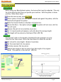
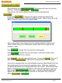
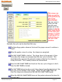
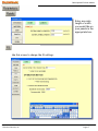
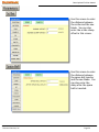
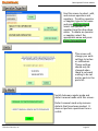
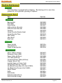
Defect, Optimize, & More
RazorOptimal End-User Manual
Page
3
4
5
6
7
8
Parts List Processor
First Use Setup
Operations
Defecting
Scanning and Cutting
Razor Optimal Screens
15
Parameters
21
21
22
22
22
23
23
24
Display Labels
Sorting
Operator/Supplier
Units
OP Mode
Setup
Startup Settings
Routine Maintenance
8
9
13
14
14
15
15
16
17
17
18
18
19
19
19
20
20
Technical Services, Inc
Topic
Main Screen
Parts List
Labels
View Cut Parts
More
Position
Motion
Saw
Panels
Fit
Scan
Parts
Encoder
COM
Reports
Scribe
Spaceball
Page 2
RazorOptimal End-User Manual
Before any file can be used with the RazorOptimal software, it must be run
through the Parts List Processor. See your Parts List Processor manual for
further instruction.
Technical Services, Inc
Page 3
RazorOptimal End-User Manual
Before using your RazorOptimal system, the home offset must be adjusted. This only
has to be done the first time you operate your machine. With the pusher in Home
position, follow these steps:
From the main screen, press
Place a piece of stock with one square trimmed end against the pusher, with the
trimmed end against the pusher.
Enter the Current Position in the Move to Position box
Choose the Move + Saw option and press
saw will cycle.
. The pusher will not move, but the
Measure the part cut as accurately as you can.
Cut 3-4 more boards and measure, and write down the average length.
This length will be entered as the Home Offset. (PG 15)
The saw kerf refers to the amount of material the saw removes in a cycle.
Using the Saw Stop screen, follow the steps below to obtain the saw kerf.
Cut a board to some length. Measure it precisely.
Cut the same board into two pieces.
Precisely measure the two pieces.
Subtract the length of the two pieces from the length of the original
board. This quantity is the saw kerf. (PG 16)
Board starts out this long.
11.000
3
4
0.125
4.000
6.875
Cut board in two and measure the two parts made from that board.
Subtract the lengths of the two parts from the length the
board was to start with to get the KERF:
11.000 - 4.000 - 6.875 = .125 = KERF
Technical Services, Inc
Page 4
RazorOptimal End-User Manual
To begin cutting parts, follow the steps below
1
3
Press
Select the cutlist you want to open. When the cutlist opens, it will be sorted
by material type. Types are determined by the species, thickness, and width
of the wood.
Choose a type you wish to run. Use the navigation keys to change type. Use
the
button to see all remaining types.
Place a piece of stock matching the material type you are running on the table.
Technical Services, Inc
Page 5
RazorOptimal End-User Manual
Feed Direction
Mark the leading edge trim cut (Required).
Mark the beginning and end of each defect.
Mark the trailing edge trim cut (Optional).
If you prefer to cut out the crayon marks, press settings, then scan. This
screen will allow you to adjust how far away from the crayon mark the
RazorOptimal will cut.
Put the board against the hard stop.
Put the joystick against the hard stop.
For defects that are unacceptable for all applications:
Pull the defecting trigger at the beginning of the defect.
Move the joystick to the end of the defect.
Release the trigger.
For defects that are acceptable for some applications:
Press and hold the defect button at the beginning of the defect.
Move the joystick to the end of the defect.
Release the defect button.
When you reach the end of the board, press the end of board button.
Technical Services, Inc
Page 6
RazorOptimal End-User Manual
After defecting, press
The scanner will move to scanning
position. Then press
or
.
Scan and Go will scan for defects and start cutting automatically.
If you push
, a diagram will appear showing the defects the
fluorescent crayon scanner picked up during the scan. Defects show up in red
bands, and clear spans show up in green bands.
This is a good idea to use when you’re just getting started so that you can
check to make sure you’re making the crayon marks dark enough for the
scanner to read.
Press
to accept the scan and start cutting parts.
Press
to accept the scan and return to the main screen where
you’ll have to press GO to continue
Press
to clear the scan and start over. If you press
, then you’ll
have to press
to delete that scanned board from the queue.
Once you’ve accepted the scan and initiated process the RazorOptimal will cut
the optimal parts from the board to minimize waste. While the machine is
processing the board you can begin defecting a new board. When the previous
board is finished the pusher will return to the scan start position so you won’t
have to push
every time. Just place the defected board
against the fence, crowd it against the back of the pusher foot, and press
either
or
.
Technical Services, Inc
Page 7
RazorOptimal End-User Manual
Most buttons on the main screen have been covered in the preceding text.
Those that weren’t covered are rather self-explanatory.
If you wish to pause the run, press
press
.
. If you wish to cancel the scan,
The information at the bottom of the screen is for display purposes only. The
buttons on the left side take you to various other screens.
Technical Services, Inc
Page 8
RazorOptimal End-User Manual
When you press
on the main screen, the following screen appears.
Delete Parts (Standard and Panel Parts)
Most of the buttons are self-explanatory. If you wish to delete a part
from the list, highlight the part with your finger and press
. If you have a keyboard handy, hold down the
ctrl key while you are selecting parts to select multiple parts to
delete.
Technical Services, Inc
Page 9
RazorOptimal End-User Manual
Edit Standard Part Quantity
2
5
4
3
Select the part of which you wish to change the quantity.
Enter the desired quantity in the New Qty Left box.
Press
Press
. This will save the quantity changes
If you do not want to save changes, press
Technical Services, Inc
.
Page 10
RazorOptimal End-User Manual
Edit Panels
Select the part you would like to change.
Adjust the number of panels and the new width cut for the selected part.
When you are done editing your panels, press
If you wish to exit without saving, press
Technical Services, Inc
.
.
Page 11
RazorOptimal End-User Manual
Add Manual Parts
This screen exists for
the purpose of adding
parts to the current
cutlist manually at the
machine. We call these
parts Manual Parts.
When you add them to
the cutlist they will
appear with a material
type of MANUAL.
Manual Parts of differing
thickness and width will
be grouped accordingly.
The labels printed for
Manual Parts will not have any information that is not on this screen. Pieces
of information such as Cabinet Number or Job Number that may be present for
parts coming from a cabinet design software package will not show up on parts
added to the cutlist manually.
To add Manual Parts:
Fill in the Quantity, Thickness, Width, and Length fields, then press
to add those parts to the main cutlist.
The
button will delete all manual parts ever
entered into the cutlist. If you wish to delete individual manual part groups
from the cutlist use the
screen.
When you’re done adding parts manually just press
.
Technical Services, Inc
to return to the
Page 12
RazorOptimal End-User Manual
1
2
3
Here you can enable or disable label printing by checking or un-checking the
box next to PRINT LABELS in the upper left corner of the screen.
You can also set the Print Head Offset. This value is the distance from the
print head to the saw blade.
Select the information you want printed on your parts using the drop-down
menus.
Technical Services, Inc
Page 13
RazorOptimal End-User Manual
The View Cut Parts screen is an easy
interface to see what parts have been cut.
You can also return parts to the cutlist by
pressing
. To
delete the top board, press
.
The screen below will take you to numerous operations. Each option on this
screen will be explained in further detail on the following pages.
Technical Services, Inc
Page 14
RazorOptimal End-User Manual
Enter the Lower
Limit Offset value
here. It tells the
pusher how far
from the saw it is
when at the lower
limit.
If the RazorOptimal
jams and you need
to back it up to clear the jam, this
value is the distance it will back up
when pressing unload.
This screen is where you set the speed of the carriage. Acceleration and
deceleration can also be set in this screen.
Technical Services, Inc
Page 15
RazorOptimal End-User Manual
This screen can
help you get the
most productivity
out of your
RazorOptimal.
The saw cycle is
where you can
gain the most
speed out of the
system so playing
with these timers
to fine-tune your
process is crucial
to getting all the
productivity you
can out of the
machine.
Basically the cycle can be described this way:
The RazorGage pusher advances the board the proper amount to achieve a
length
When the pusher comes to a stop, the clamps are energized.
The SAW CLAMP TIMER is started. The clamp timer is the amount of time
from when the clamps are energized and the saw cycle is started. This
should basically represent the amount of time it takes for the clamps to
clamp the board. This is usually around 100 milliseconds.
Once the SAW CLAMP TIMER has timed out the saw cycle is begun at which
time the SAW TIMER is started.
The SAW TIMER determines how much time elapses from the beginning of the
saw cycle to the release of the clamps. When the SAW TIMER times out
then the clamps are released and the SAW UN-CLAMP TIMER begins.
When the SAW UN-CLAMP TIMER times out the pusher advances the board to
the next part.
Technical Services, Inc
Page 16
RazorOptimal End-User Manual
Enter any extra
length or width
you would like on
your panels in the
appropriate box.
Use this screen to change the fit settings.
Technical Services, Inc
Page 17
RazorOptimal End-User Manual
This screen is where you can adjust your defecting scan settings.
Use this screen to track how many parts have been cut on your RazorOptimal.
To reset the counter, press
.
Technical Services, Inc
Page 18
RazorOptimal End-User Manual
The encoder screen is password protected. The parameters change the
settings of the encoder and should not be changed.
Use this screen to enter
the COM interval.
The reports settings allow you to enable or disable generating yield reports.
To change where the reports are saved, press
.
Technical Services, Inc
Page 19
RazorOptimal End-User Manual
Use this screen to enter
the distance between
the scribe and the saw
blade. You can also
enter the scribe clamp
offset in this screen.
Use this screen to enter
the distance between
the space ball inserter
and the saw blade. You
can also enter the
delay after the space
ball is inserted.
Technical Services, Inc
Page 20
RazorOptimal End-User Manual
Here you can edit the
user defined parts
fields. You can also
select which labels
are displayed in the
parts list by checking
or un-checking the
“Display in Parts List”
checkbox.
Change the order in
which parts are
sorted. Highlight the
field you wish to sort
by, and press the
button to add it to
the list. To shift a
field up or down,
highlight the field
and press
or
.
Technical Services, Inc
Page 21
RazorOptimal End-User Manual
Use this screen to select, add,
and remove operators and
suppliers. To add an operator
or supplier, type in the name
and press
.
Select the operator or
supplier from the drop-down
menu. To delete an operator
or supplier, select the
appropriate name and press
.
This screen will
change your units
settings to inches
or millimeters.
Theses settings
should only be
changed when
there is no board
waiting to be cut
and no parts in the
parts list.
Switch between regular mode and
defect removal mode with this screen.
Defect removal mode only removes
defects that have been marked. It
does not perform operations from a
cutlist.
Technical Services, Inc
Page 22
RazorOptimal End-User Manual
The setup screen is password
protected. These settings
should not be changed.
These are the settings for
the options and accessories
you have installed with your
RazorOptimal.
These are pre-set from the
factory, but can be changed
if you order additional
components.
Technical Services, Inc
Page 23
RazorOptimal End-User Manual
Your RazorGage is greased before shipping. The bearing rail is a one-time
grease rail, so no periodic greasing is required.
Part
Part No
Bearing Rail
Drive Belt
Drive Pulley
M-Drive Rotary Encoder
M-Drive Linear Encoder
Gearbox
Linear Encoder Reader Head
Linear Encoder Tape
Idler Pulley
Idler Block
Dust Seal
RG10028
RG10108
RG10037
RG10984
RG10985
RG10978
RG10091
RG10109
RG10031
RG10030
RG10123
Power Switch
Solid-State PC
Touch Screen Monitor
RG11016
RG10973
RG10740
Motor Cable (2 Meter)
Extension Cable (USB)
Power Cable (M-Drive)
I/O Cable (M-Drive)
Communications Cable (M-Drive)
Crayons (Box of 50)
Joystick Laser w/ Power Cord
Flex Rated Cable for Joystick
Ink (Black Porous) Box of 6 (Cart #4500)
Ink (Black Non-Porous) (Cart #4600)
Inkjet Printer
Drills
Drill Holder
Drill Drive Belt (Short)
Drill Drive Belt (Long)
RG10672
RG10610
RG10988
RG10987
RG10986
RG10844
RG10180
RG10181
RG10952
RG10957
RG10951
RG10816
RG10889
RG10936
RG10937
Technical Services, Inc
Page 24
RazorOptimal End-User Manual
Phone
515.232.3188
Fax
515.232.2953
Email
[email protected]
Online
http://www.razorgage.com
In Person
57006 241st Street
Ames, IA 50010
Technical Services, Inc
Page 25