1
®
®
USER'S MANUAL
Copyright © 1992-2005 Bertrand Lenoir-Welter
All rights reserved
As with previous versions, the development of Galaad 3 has been greatly
helped by three professional users, who have made numerous suggestions and
given up a great deal of their time to the fiery - sometimes explosive prototypes. Simple thanks can never be enough for the contributions that
these three people have made towards the development of this software,
however, it would be improper if they were not named here.
Without doubt, recognition goes to Patrice Berger, a model maker near
Annecy, France, and an old friend of Galaad, with which he makes many
beautiful things; Christian Goubin, a technology teacher near Vannes,
France, and an insufferable supporter based on the number of suggestions
that he has made; and finally, Yves Laporte (Prestical Company), a
polystyrene carver near Bordeaux, France, also notoriously unlucky when it
comes to stumbling across unbelievable bugs. These three dangerous
pyromaniacs have been the cause of many a late night but, in the end, it was
all worth it for the good of the project.
Simply thank you.
B. Lenoir-Welter
April 1999 - July 2005
COPYRIGHT / RESPONSABILITY
Copyright ? 1992-2005 Bertrand Lenoir-Welter / All rights reserved
No part of this software and user's manual may be reproduced or
transmitted, in any form or by any means, for any purpose whatsoever,
without the written permission of the author. To do so constitutes a forgery
punishable under local law and international copyright treaty.
Any person legally acquiring this software is permitted to make copies of
it on the condition that it is strictly in accordance with the terms of licensing
agreement in their possession; namely that it is for evaluation purposes only
and not for commercial gain. Integrating this software, either totally or in
part, with another piece of software constitutes a breach of copyright.
Moreover, no part of the software may be disassembled or de-compiled, in any
way, without the written consent of the author.
Galaad is supplied as is, and no guarantee is given or implied as to the
results obtained by its use, or regarding overall satisfaction with the end
product. Galaad is a complex piece of software and has been extensively
tested, however, these tests are not guaranteed to have removed all bugs and
minor errors from the software. Finally, no guarantee can be given that
subsequent versions will necessarily be compatible with existing versions.
The user is solely responsible for using the software and ensuring that the
results obtained by using it are those expected. No responsibility will be
attributed to Galaad, its authors or distributors, for any damage caused, either
directly or indirectly, to the machine tool, any peripheral devices, cutters,
stored data, or any other object including hardware and software involved in
the usage of Galaad.
None of the above terms and conditions affect your statutory rights under
current law or legislation.
NEMO LEGEM IGNORARE CENSETVR
(Ignorance of the law is no excuse)
— — — — — — — — — — — — — — — — — — — — — — — — — — — — — — — — — —
TABLE OF CONTENTS
FOREWORD
Little Curriculum Vitæ . . . . . . . .
The User's Licence and working without a licence
System configuration . . . . . . . .
Be inquisitive! . . . . . . . . . .
.
.
.
.
.
.
.
.
.
.
.
.
.
.
.
.
12
13
15
16
1 - INSTALLATION
Setup . . . . . . . . .
Software driver for the dongle-key
The lay of the Land
. . . .
Moving Galaad . . . . . .
Uninstalling Galaad
. . . .
.
.
.
.
.
.
.
.
.
.
.
.
.
.
.
.
.
.
.
.
.
.
.
.
.
.
.
.
.
.
.
.
.
.
.
.
.
.
.
.
1-18
1-20
1-21
1-21
1-22
2 - LEARNING TO DESIGN
Contact . . . . . .
Baby steps
. . . .
Simple co-ordinates
. .
Snapping to positions . .
Handling objects
. . .
The magnetic grid . . .
De profundis
. . . .
Zoom
. . . . . .
.
.
.
.
.
.
.
.
.
.
.
.
.
.
.
.
.
.
.
.
.
.
.
.
.
.
.
.
.
.
.
.
.
.
.
.
.
.
.
.
.
.
.
.
.
.
.
.
.
.
.
.
.
.
.
.
.
.
.
.
.
.
.
.
.
.
.
.
.
.
.
.
.
.
.
.
.
.
.
.
2-24
2-26
2-27
2-29
2-30
2-33
2-34
2-36
3 - LEARNING TO MILL
Technical control . . . .
Guided tour of the launch pad
Workpiece origin . . . .
Blast off
. . . . . .
.
.
.
.
.
.
.
.
.
.
.
.
.
.
.
.
.
.
.
.
.
.
.
.
.
.
.
.
.
.
.
.
.
.
.
.
3-38
3-39
3-41
3-45
4 - LEARNING TO SAVE FILES
Current design . . . . . .
Files and folders
. . . . .
.
.
.
.
.
.
.
.
.
.
.
.
.
.
.
.
4-48
4-49
— — — — — — — — — — — — — — — — — — — — — — — — — — — — — — — — — —
— — — — — — — — — — — — — — — — — — — — — — — — — — — — — — — — — —
5 - ADVANCED DESIGN TECHNIQUES
Numerical co-ordinates
. . . . .
Partial constructions
. . . . . .
Editing object geometry
. . . . .
Locking objects . . . . . . . .
Associating objects . . . . . . .
Protecting objects . . . . . . .
Anchoring objects . . . . . . .
Selecting and handling points . . . .
Selecting and handling segments .
.
Moving groups of points . . . . .
Duplication and cloning
. . . . .
Rapid data palettes . . . . . . .
Keyboard shortcuts . . . . . . .
Display functions . . . . . . .
.
.
.
.
.
.
.
.
.
.
.
.
.
.
.
.
.
.
.
.
.
.
.
.
.
.
.
.
.
.
.
.
.
.
.
.
.
.
.
.
.
.
.
.
.
.
.
.
.
.
.
.
.
.
.
.
.
.
.
.
.
.
.
.
.
.
.
.
.
.
.
.
.
.
.
.
.
.
.
.
.
.
.
.
5-52
5-53
5-55
5-56
5-56
5-57
5-58
5-59
5-62
5-64
5-64
5-67
5-68
5-70
6 - TOOLPATHS
Tool parameters . . . . . .
Tool compensation . . . . .
Hatching and pocketing cycles . .
Connecting objects into one toolpath
.
.
.
.
.
.
.
.
.
.
.
.
.
.
.
.
.
.
.
.
.
.
.
.
.
.
.
.
6-72
6-78
6-82
6-85
7 - ADVANCED MILLING FUNCTIONS
Tool parking positions . . . . . .
1st pass, 2nd pass, cutting pass . . . .
Fixed values . . . . . . . . .
Design . . . . . . . . . .
Advanced options . . . . . . .
Moving the axes
. . . . . . .
Defining the workpiece origin
. . .
Automatic tool measurement . . . .
Manual control . . . . . . . .
Galaad and Lancelot
. . . . . .
.
.
.
.
.
.
.
.
.
.
.
.
.
.
.
.
.
.
.
.
.
.
.
.
.
.
.
.
.
.
.
.
.
.
.
.
.
.
.
.
.
.
.
.
.
.
.
.
.
.
.
.
.
.
.
.
.
.
.
.
7-88
7-90
7-92
7-92
7-94
7-96
7-101
7-103
7-106
7-107
8 - WORKSPACE PARAMETERS
General . . . . . . . .
Advanced functions
. . . .
Restrictions for education . . .
.
.
.
.
.
.
.
.
.
.
.
.
.
.
.
.
.
.
8-110
8-111
8-113
.
.
.
.
.
.
.
.
.
.
— — — — — — — — — — — — — — — — — — — — — — — — — — — — — — — — — —
— — — — — — — — — — — — — — — — — — — — — — — — — — — — — — — — — —
9 - MACHINE PARAMETERS
Main parameters
. . . . . . . .
Table . . . . . . . . . . . .
Numerical controller . . . . . . .
Isel IMS6 controller . . . . . . . .
SM-Motion 300 & 400 controllers
. . .
TechLF CNC-4AX/4BX & 8AM controllers
Solectro SML-33 controller
. . . . .
Generic controllers . . . . . . . .
Spindle . . . . . . . . . . .
Tachometric spindle on analogue output
.
Tachometric spindle on PWM output
. .
Tachometric spindle on multiple binary outputs
Programmed sequence of commands . . .
External control programme . . . . .
Custom spindle commands
. . . . .
Speeds . . . . . . . . . . .
Advanced parameters . . . . . . .
The hunt for bugs . . . . . . . .
Automatic tool changer
. . . . . .
Inputs / outputs
. . . . . . . .
Extended inputs / outputs . . . . . .
Local manual drive . . . . . . . .
External driver . . . . . . . . .
.
.
.
.
.
.
.
.
.
.
.
.
.
.
.
.
.
.
.
.
.
.
.
.
.
.
.
.
.
.
.
.
.
.
.
.
.
.
.
.
.
.
.
.
.
.
.
.
.
.
.
.
.
.
.
.
.
.
.
.
.
.
.
.
.
.
.
.
.
.
.
.
.
.
.
.
.
.
.
.
.
.
.
.
.
.
.
.
.
.
.
.
.
.
.
.
.
.
.
.
.
.
.
.
.
.
.
.
.
.
.
.
.
.
.
10 - USING A NETWORK
Sharing disks & folders
Main workstation . .
Secondary workstations
Exchanging files
. .
.
.
.
.
.
.
.
.
.
.
.
.
.
.
.
.
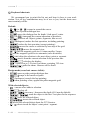
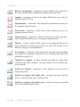
11 - OVERVIEW OF DESIGN ICONS
Points
. . . . . . . . .
Lines
. . . . . . . . .
Polylines (and curves) . . . . .
Rectangles (and polyhedrons) . . .
Arcs (and cyclic shapes) . . . . .
Text . . . . . . . . . .
Selections
. . . . . . . .
9-120
9-123
9-124
9-127
9-128
9-129
9-130
9-130
9-131
9-133
9-133
9-134
9-135
9-135
9-136
9-137
9-139
9-142
9-143
9-144
9-145
9-146
9-147
.
.
.
.
.
.
.
.
.
.
.
.
.
.
.
.
.
.
.
.
.
.
.
.
. 10-150
. 10-151
. 10-152
.
.
.
.
.
.
.
.
.
.
.
.
.
.
.
.
.
.
.
.
.
.
.
.
.
.
.
.
.
.
.
.
.
.
.
.
.
.
.
.
.
.
.
.
.
.
.
.
.
10-153
11-156
11-157
11-159
11-160
11-162
11-164
11-165
— — — — — — — — — — — — — — — — — — — — — — — — — — — — — — — — — —
— — — — — — — — — — — — — — — — — — — — — — — — — — — — — — — — — —
Special effects .
Milling data . .
Zoom . . . .
Visual dimensions
.
.
.
.
.
.
.
.
.
.
.
.
.
.
.
.
.
.
.
.
.
.
.
.
.
.
.
.
.
.
.
.
.
.
.
.
.
.
.
.
.
.
.
.
.
.
.
.
.
.
.
.
11-167
11-169
11-170
11-171
12 - OVERVIEW OF MENUS
"File" menu
. . . . .
"Machine" menu
. . . .
"Edit" menu . . . . . .
"Design" menu . . . . .
"Display" menu . . . . .
"Text" menu
. . . . .
"Parameters" menu . . . .
"Help" menu
. . . . .
.
.
.
.
.
.
.
.
.
.
.
.
.
.
.
.
.
.
.
.
.
.
.
.
.
.
.
.
.
.
.
.
.
.
.
.
.
.
.
.
.
.
.
.
.
.
.
.
.
.
.
.
.
.
.
.
.
.
.
.
.
.
.
.
.
.
.
.
.
.
.
.
12-174
12-179
12-185
12-191
12-202
12-210
12-211
12-214
13 - SPECIAL FUNCTIONS
Got a head for maths? . .
3-D meshes . . . . .
.
.
.
.
.
.
.
.
.
.
.
.
.
.
.
.
.
.
13-216
13-221
.
.
.
.
.
.
.
.
.
.
.
.
.
.
.
.
.
.
.
.
.
.
.
.
.
.
.
.
.
.
.
.
.
.
.
.
.
.
.
.
.
.
.
.
.
14-228
14-229
14-231
14-232
14-235
TURNING CAD/CAM
. . . . . . . .
. . . . . . . .
. . . . . . . .
. . . . . . . .
. . . . . . . .
.
.
.
.
.
.
.
.
.
.
.
.
.
.
.
15-238
15-242
15-243
15-245
15-246
.
.
.
.
.
.
.
.
.
.
.
.
.
.
.
16-248
16-251
16-254
16-256
16-257
.
.
14 - "KAY", 3-D CNC DRIVER
General . . . . . . .
File origin & co-ordinates . .
Workpiece origin . . . .
Parameters . . . . . .
Milling . . . . . . .
15 - "GAWAIN", 2 AXES
Non-indexed turning .
Lathe parameters . .
Tour of the launch pad .
Workpiece origin . .
Automatic process . .
16 - "KYNON", MOTION PROGRAMMER
Automaton for axis controls . . . . .
Programming technique
. . . . . .
Motion commands . . . . . . . .
Switch and pause commands . . . . .
Jump commands
. . . . . . .
.
.
.
.
.
.
.
.
.
.
— — — — — — — — — — — — — — — — — — — — — — — — — — — — — — — — — —
— — — — — — — — — — — — — — — — — — — — — — — — — — — — — — — — — —
Macro-commands . . . . .
Programme management commands
Manual drive teach-in . . . .
User-defined buttons
. . . .
.
.
.
.
.
.
.
.
.
.
.
.
.
.
.
.
.
.
.
.
.
.
.
.
.
.
.
.
.
.
.
.
16-258
16-260
16-261
16-262
17 - "PERCIVAL", PRINTED-CIRCUIT ENGRAVER
General features . . . . . . . . . . . .
Gerber files . . . . . . . . . . . . .
Excellon files
. . . . . . . . . . . .
Extracting contours . . . . . . . . . . .
Hatching empty zones . . . . . . . . . .
Boring drills
. . . . . . . . . . . .
Milling . . . . . . . . . . . . . .
.
.
.
.
.
.
.
.
.
.
.
.
.
.
17-264
17-265
17-266
17-267
17-268
17-269
17-270
.
.
.
.
.
20-278
20-280
20-282
20-283
20-284
18 - "OWEIN", GRAPHICAL TOOLPATH BROWSER
19 - FREQUENTLY ASKED QUESTIONS
20 - TECHNICAL MATTERS
Command line arguments . . .
Integration into an automated chain
Interface with Windows
. . .
TrueType and Galaad fonts
. .
Downloading the latest updates .
.
.
.
.
.
.
.
.
.
.
.
.
.
.
.
.
.
.
.
.
.
.
.
.
.
.
.
.
.
.
.
.
.
.
.
21 - GLOSSARY OF TERMS
— — — — — — — — — — — — — — — — — — — — — — — — — — — — — — — — — —
— — — — — — — — — — — — — — — — — — — — — — — — — — — — — — — — — —
0
— — — — — — —
0 0 0 0 0
FOREWORD
— — — — — — — — — — — — — — — — — — — — — — — — — — — — — — — — — —
GALAAD
3 —————————————————————————————
Brief Curriculum-Vitae
Galaad is a CAD/CAM/CNC software package (Computer Aided Design /
Computer Aided Manufacturing / Computerised Numerical Control), the
point of which is to enable you to design, i.e. draw, then manufacture, i.e.
mill, parts or objects that you need. In view of the geometrical nature of most
components and the associated toolpaths, this requires a classical approach to
the design work. Galaad is a single integrated package that covers all
aspects from drawing through to controlling the milling machine, and not
simply a collection of different applications. This integration in a
homogeneous set offers many advantages, making it easier both to learn and
to use, even for absolute beginners.
It is important to mention here that, in spite of its name, Galaad 3 is not
3-D design software. Its application domains are mainly engraving and
cutting works on plane materials. Galaad provides special functions that
create 3-D wiremeshes, for example cut profiles or curve surfaces; it accepts
3-D handling and effects; it can import and mill 3-D external files, but it
cannot create, handle, import or mill volumes that are made of facetted or
NURBS surfaces. Only 3-D vector trajectories that represent a toolpath are
accepted. Therefore if you already have a 3-D CAD system that handles
surfaces and volumes, you need an intermediate module that can convert these
shapes into vectors which define a final toolpath. Only then can you mill
these 3-D vectors using Galaad.
Galaad 3 is designed to be used on a PC running Windows 95, 98, ME,
NT-4, 2000, XP and whatever Microsoft has in store for our wonderful future.
It can drive a number of CNC machines with 2, 3, 4 or 5 axes, either directly
or by using an external driver programme. It may also be encapsulated in a
wider processing chain. Consequently, Galaad can be considered an open
application. We will see more later about the machines covered and details on
how to configure them.
Additional programmes and icons appear when installing Galaad,
enabling you to make non-indexed turning, automatic motion programming,
printed-circuit engraving, or 3-D milling up to 5 axes. These extra modules
are described in the last chapters of this manual.
12 —
Foreword — — — — — — — — — — — — — — — — — — — — — — — — — —
— — — — — — — — — — — — — — — — — — — — — — — — — — — — —
GALAAD
3
The User's Licence and working without a licence
As with most software, Galaad is the result of a lengthy development
period and is therefore not freeware. If you are reading this manual, it is
likely that you have legally obtained a copy together with a licence. The terms
of this licence concern you all the same as you may need to make authorised
copies of the software.
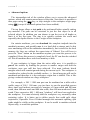
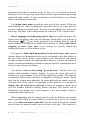
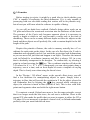
The user licence for Galaad is always in the form of an
electronic protection key, commonly called a dongle. Depending
on its type, the dongle must be plugged into the LPT port
(printer port) or a USB port on your PC so that Galaad can read
it and thereby give you full access to all features.
Not having a dongle is in effect not having a user licence,
which will prevent Galaad from communicating with the outside
world. In this case, it will neither be possible to execute the
milling process, nor export any designs to another software
package, including using copy/paste. You will however be able to
save designs and drive your machine manually, even though
automatic machining will not be accessible.
For professional licences, it is not necessary to have the key attached
to the parallel port of your PC at all times; Galaad can simply re-enable the
licence monthly. At the appropriate time, it displays a message requesting you
to attach the key to the port for a moment, so the licence may be refreshed.
This restricted functionality is deliberate for several reasons. Firstly, it
allows the software to be copied legally for evaluation purposes by potential
users. Secondly, a user of Galaad may well wish to install it on several
computers dedicated to designing and reserve a single PC for driving the
CNC. An unlicensed version is no less subject to the current legislation
covering intellectual property rights.
You have the right to copy the Galaad 3 CD-ROM, or its
downloadable version, for your own use or for distribution. This is
provided that the contents are not modified in any way, that all copyrights are acknowledged, and that there is no possibility, even indirectly,
of designs being manufactured with the software without a user licence.
— — — — — — — — — — — — — — — — — — — — — — — — — —
Foreword —
13
GALAAD
3 —————————————————————————————
There are three types of user licence available. The professional licence is
the main one, and is for those who wish to use the software to design and
manufacture objects for commercial gain. There are no restrictions with this
licence. The educational licence, as its name implies, is restricted to use in a
training environment where there is no commercial gain, either directly or
indirectly, from any objects manufactured. Finally there is the hobby licence,
which has milling time restrictions and can be sold only to associations.
Using an educational or hobby licence must have no direct or indirect
commercial purpose.
There is no difference in the functionality of the software under the
different licences, with the educational or hobby version having all the
functionalities and features of the professional version (except milling time
restrictions for hobby). Only the terms of use are different. Consequently,
using an educational or hobby version to manufacture objects for
commercial gain is a violation of the licensing agreement.
Some subsets of Galaad may be sold separately at a lower price, in which
case, the corresponding licence is valid for these modules only. Conversely
the normal user's licence of Galaad covers all modules, this is not the forced
sale of useless modules, simply the standard Galaad licence provides access to
all features.
If you have any questions relating to the licence that you have been
supplied with, do not hesitate to contact your supplier. Remember that if you
have been sold a copy legally it will come with a dongle.
For further information, or in case of difficulty we invite
you to visit the official Galaad web site at www.galaad.net
Note: are fully recognised all registered trademarks and the corresponding owners' rights that
may appear in this manual.
14 —
Foreword — — — — — — — — — — — — — — — — — — — — — — — — — —
— — — — — — — — — — — — — — — — — — — — — — — — — — — — —
GALAAD
3
System configuration
For those who are interested in the details, Galaad 3 was developed during
1998/9 using Borland C++ 5.02 OWL on two PCs linked by Ethernet. One
fitted with a 350 MHz AMD K6-3D processor and 256 Mb RAM running
Windows 98 version 4.10.1998 for the development;the other fitted with a
120 MHz Cyrix P6 and 64 MB RAM running Windows 95 4.00.950a for
testing. The code was compiled as 32 bits for an i486 processor with a maths
co-processor. In simple terms this means that Galaad 3 will run neither on a
PC fitted with an i486 SX or SXT processor or earlier, nor under Windows
3.11 or earlier, if such systems are still in use somewhere on this Earth.
-
Strict minimum specification is:
50 MHz i486 DX processor
16 Mb RAM
30 Mb of available disk space
640 ? 480 ? 16 VGA graphics adapter
mouse or equivalent pointing device
Windows 95 operating system
Obviously Galaad will feel happier (it’s likely that you will too) with a
more powerful PC, as described below. The recommended configuration is at
least a 200 MHz processor with 64 Mb RAM, a graphics card with
1024 ? 768 ? 256 resolution and a small joystick. By the time you read this,
the most basic machine available will probably be much more powerful than
this. Note that Galaad is not a particularly demanding piece of software and
there is little point in buying the latest state of the art PC for it, you would
be better off buying a high quality monitor.
Note: do not dismiss the idea of a joystick,
as it frequently proves ideal for controlling a
machine in manual mode. See chapter 7 on
advanced milling functions for more
information on configuring and using a
joystick.
— — — — — — — — — — — — — — — — — — — — — — — — — —
Foreword —
15
GALAAD
3 —————————————————————————————
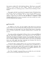
Be inquisitive!
Whatever you may get out of this manual, you will no
doubt learn mostly by actually using the software. There will
always be those complex functions that you will have to refer
to the manual to find your way through, however, your best
bet both now and in the future, is probably to follow your
instinct.
Galaad is house trained and so won't actually bite when you make a
mistake. At worst, it will send you a disapproving warning, which will no
doubt be bearable in view of the relationship you should have established with
Galaad (at least from Galaad's point of view).
So don't hesitate in learning what
Galaad 3 can do, there is no shame in being
a beginner and consequently no reason to be
shy. If you have any doubts about how a
function works, the best way to find out is
to jump in and try it, even if the end result
is quite what you expected; you can always
cancel if things do not go to plan. Trial and
error is often the best way to learn how
software really works! Galaad is no
exception.
16 —
Foreword — — — — — — — — — — — — — — — — — — — — — — — — — —
— — — — — — — — — — — — — — — — — — — — — — — — — — — — — — — — — —
1
— — — — — — —
0 0 0 0 1
INSTALLATION
— — — — — — — — — — — — — — — — — — — — — — — — — — — — — — — — — —
GALAAD
3 —————————————————————————————
Setup
Galaad 3 is supplied on a CD, which contains
all the files that will be transferred onto your hard
disk. The installation program will normally start
automatically a few seconds after the drive door
has been closed.
Under certain circumstances the "AutoRun" fails to start, depending on
your Windows configuration. In this case it is necessary to run the
SETUP.EXE programme on the CD, using the "Start" button and the "Run"
option. If your CD drive corresponds to the D unit, which generally occurs on
a basic PC, type D:SETUP and click on OK.
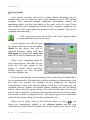
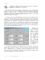
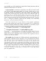
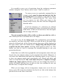
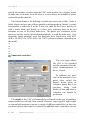
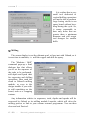
When the SETUP program
is run, be it automatically or
manually, it produces a blue
screen and a series of dialogue
boxes to enable the installation
to be configured according to
your wishes.
The first one asks the usual
question regarding where you
wish to install Galaad on your
hard disk. The default folder is
C:\GALAAD, but the choice is
yours.
If you wish to install Galaad into another folder, simply type in its name
or use the "Browse" button, which will open a small window enabling you to
browse the directory tree and select a destination folder. It is not necessary to
install Galaad in the default directory or even on a local hard disk. What is
more Galaad does not modify any files other than those in its own folder,
except for desktop shortcuts to it. In particular, the innumerable system files
associated with the Windows galaxy are not affected by the installation of
Galaad onto your hard disk.
1 - 18 —
Installation
— — — — — — — — — — — — — — — — — — — — — — — —
— — — — — — — — — — — — — — — — — — — — — — — — — — — — —
GALAAD
3
A standard installation of Galaad 3 requires
30 Mb of space available on your hard disk, plus
some for storing your own designs.
Installation from an Internet download contains
less Galaad fonts and design samples, it therefore
requires less disk space.
Finally, the SETUP program performs the little additional Windows setup
tasks, namely the addition of shortcuts for starting Galaad and the association
of GAL files with Galaad so that opening them will start Galaad
automatically. If you do not require these additional features, untick the
appropriate boxes at the bottom of the window.
Then click on the "Next >>" button.
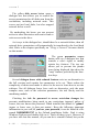
It is now necessary to tell
Galaad the general characteristics of your CNC machine,
if one is actually connected to
this workstation. If not, do not
waste your time going into
detail, just validate this page as
it is.
Note that these parameters
can be modified after Galaad
has been installed, errors can
therefore be fully corrected at a
later date.
If you are installing Galaad onto a workstation connected to a CNC
machine, select the option that will allow you to specify the type of machine
and the communications port to which it is connected.
Click on the "Next >>" button one last time. A final dialogue box will
appear confirming the folder into which Galaad will be installed and showing
the software licensing agreement, which you are, of course, already familiar
with, having read the previous chapter.
— — — — — — — — — — — — — — — — — — — — — — — —
Installation —
1 - 19
GALAAD
3 —————————————————————————————
Now click on the "Install" button, which will start the installation process
and transfer files from the CD to your hard disk. This can take from fifteen
seconds to more than a minute, depending on the type of installation and the
performance of your machine. A progress bar shows how things are
proceeding and a message confirms when the process is complete.
Following this message you can start Galaad for the first time and
thereafter by using the icon that has been placed on the desktop or the
shortcut created in the "Start" menu. Your installation is now complete.
Software driver for the dongle-key
Unlike with Windows 95/98/ME, direct communication between Galaad
and its dongle key, plugged onto the printer port or a USB port, cannot take
place under Windows NT kernels, including Windows 2000 (NT-5),
Windows XP (NT-5.1) and subsequent versions. With such operating systems,
it is necessary to use a specific software driver which handles the communication. This driver programme is located on the CD-ROM, and will be
installed automatically, after prompting you for approval. Of course, there is
no need to install it on a workstation that has no licence.
If you wish to install or reinstall this driver, open Windows Explorer,
search for Galaad 3 in its CD-ROM drive, and double-click on the
programme "DongleDriver.exe". This will load and install the appropriate
driver to allow Galaad to communicate with the dongle key.
Under certain configurations of Windows 95/98/ME, and especially when
exotic peripherals are connected to the parallel port, it is also necessary to
install the driver. If you have the USB version of the licence key, then the
driver is required anyway. Run the above-mentioned programme if you did
not allow it to install automatically. Note that Windows XP is able to detect
the USB dongle key automatically when it is plugged in, and install its own
driver.
1 - 20 —
Installation
— — — — — — — — — — — — — — — — — — — — — — — —
— — — — — — — — — — — — — — — — — — — — — — — — — — — — —
GALAAD
3
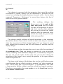
The Lay of the Land
Remember that installation does not add
any files other than to its own folder, except
for the shortcuts on the desktop and in the
"Start" menu. These are the classic LNK files
destroyed by Windows when you delete the
shortcuts.
Additionally the only modification to the Windows Registry is the
association of GAL (design files) and GLI (object libraries) files with Galaad,
which allows it to be started by double clicking on "GAL File" type files. This
association also adds the Galaad mini icon to GAL files, visible in Explorer
and Windows dialogue boxes used for file handling, thus simplifying file
identification. The above adds a grand total of three little keys to the Registry.
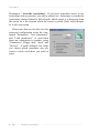
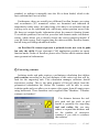
Moving Galaad
If necessary, it is possible to move the
installation to another folder with the help
of Windows Explorer by renaming the
target folder or cutting/pasting it to another
drive or subdirectory. No problem with this,
Galaad is easily moved. Don't forget to
manually redirect the Windows shortcuts on
the desktop and in the "Start" menu.
— — — — — — — — — — — — — — — — — — — — — — — —
Installation —
1 - 21
GALAAD
3 —————————————————————————————
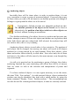
Uninstalling Galaad
It was not felt necessary to create a programme to automatically uninstall
Galaad, due to the simplicity of the installation and the absence of any files
except those in the folder into which it was installed.
To remove Galaad, it’s a case of deleting its
folder using Windows Explorer or a similar tool.
It’s that simple.
You can then manually delete the icons from
the desktop and the shortcuts in the "Start" menu,
which will remove all trace of Galaad from your
hard disk.Never again will you be bothered by
Galaad, it’s your loss.
If you are not happy with the idea of three keys remaining in the Windows
Registry, it’s pretty easy to delete them: these keys concern the links between
*.GAL files (Galaad designs) and GALAAD.EXE program; *.GLI files (Galaad
libraries) and GALAAD.EXE; and between *.GAW files (Gawain turning
designs) and GAWAIN.EXE. These keys are of no use once Galaad has been
removed from your hard disk, they will take up no space or system resources,
nor will they interfere with other applications, but you have every right to
remove the even the smallest dust Galaad may have left on your computer.
Open Windows Explorer and select the "Folder options" command
(generally found in the "Tool" menu, depending on your Windows version),
then "File types" page. Seek for the GAL, GAW and GLI extensions and
remove them with the "Delete" button. A greyed button means that the key is
already erased. The next boot of Windows will clean this up for good.
1 - 22 —
Installation
— — — — — — — — — — — — — — — — — — — — — — — —
— — — — — — — — — — — — — — — — — — — — — — — — — — — — — — — — — —
2
— — — — — — —
0 0 0 1 0
LEARNING TO DESIGN
— — — — — — — — — — — — — — — — — — — — — — — — — — — — — — — — — —
GALAAD
3 —————————————————————————————
Contact
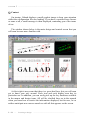
On startup, Galaad displays a small graphic image to keep your attention
whilst the configuration files are loading. If you have a restricted user licence
or none at all, a small message is then displayed, reminding you of the terms
of use.
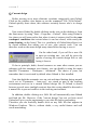
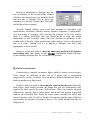
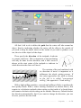
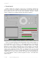
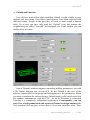
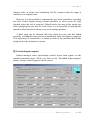
The window shown below is the main design and control screen that you
will soon become more familiar with.
At first sight it may seem that there is a great deal here, but you will soon
get to know your way around. Each icon and each display area has its
particular use. In addition, you can easily pick up the key functions available
in the menus and design icons. All will be clarified later on in the manual
when you learn how to restrict the information displayed, but for now, let us
neither anticipate nor concern ourselves with all that appears on the screen.
2 - 24 —
Learning to design
— — — — — — — — — — — — — — — — — — — — —
— — — — — — — — — — — — — — — — — — — — — — — — — — — — —
GALAAD
3
The working area is divided into five distinct zones.
-
At its centre is your drawing board. This shows the result of your
creativity, ready to be sent to the CNC to be manufactured with no further
ado. Simply, it is in this area that your design will take shape and can be
viewed from above in plan, or by using the lateral and 3-D views.
-
At the very top of the screen is a classic menu bar. This provides access to
all functions from file handling, through access to the CNC, to
manipulation of the display, and is arranged in terms of functionality.
Nothing original here, apparently even in Australia the menu bar is at the
top.
-
Immediately below is the equally classic tool bar. Each icon is a shortcut
for a function in one of the menus, which saves having to navigate
through the maze of sub-menus. Just to give Galaad a proper nonconformist feel, some of these icons also have a "fly out" icon underneath.
-
On the far left of the screen are the design icons. There you will find
plenty to stimulate your creativity, providing an array of tools for
constructing the objects that will allow you to create your design. When
the mouse pointer is passed over these icons, a group of icons will "fly
out", offering a wider range of associated functions.
-
Finally, relegated to the very bottom of the screen is the display zone. An
Aladdin’s cave of information about the current design including coordinates, dimensions and angles, packed in higgledy-piggledy.
Note: Please keep in mind that the aim of this manual is not to teach you
about the current Windows interface, which at the time of writing this manual
is supposedly nearly finished or at the very least the ground work is complete.
However, several little reminders will be given here and there, totally free, but
all the same, don't hold out for an advanced technical course on the inner
workings of Windows, which are varied, twisted and sometimes even logical.
— — — — — — — — — — — — — — — — — — — — —
Learning to design
—
2 - 25
GALAAD
3 —————————————————————————————
Baby steps
As you will discover, drawing with Galaad is not all that complicated.
However, it is necessary to remember that the object of the exercise is to
generate a toolpath for a machine cutter to follow and not just a pretty
design to be simply printed. Do not compare this with an image editor like
PaintBrush, PaintShop, PhotoShop, etc. for bitmap files, which work on a
mosaic of pixels and not co-ordinates.
Galaad CAD module is a vector graphic editor, i.e. a line is constructed by
defining the two points at its extremities then linking them; it is not simply an
array of black pixels. This calls for greater precision, and for the work to be
approached from a graphical point of view as opposed to an artistic one. If
you have already used vector design software, such as CorelDraw or Adobe
Illustrator, you will have no problem in becoming familiar with Galaad. The
modus operandi is quite conventional.
Let us begin by opening the "File" menu and clicking on
the "New" command. The current design will be removed
and replaced by a blank drawing board.
It then requests the overall dimensions of
the new workpiece. Measure your material
and enter the dimensions in the appropriate
place. These dimensions can be modified at
any time by using the following command,
"File / Material dimensions" in the same
menu. Check the values and click on OK.
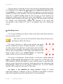
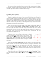
Let’s begin with something simple, like a straight line. Locate the
"line" icon in the design icons on the left-hand side of the screen,
ignoring the multitude of other icons that fly-out, the basic icon will do fine.
Click on it and return to the drawing board.
The cursor will have changed from the oblique white arrow to a red cross,
complete with cross hairs. Move the mouse and the red cross will follow its
movement along with the cross hairs which indicate the current position on
the rulers. In addition, the numerical co-ordinates are indicated at the bottom
2 - 26 —
Learning to design
— — — — — — — — — — — — — — — — — — — — —
— — — — — — — — — — — — — — — — — — — — — — — — — — — — —
GALAAD
3
of the screen and updated when the position settles. Click somewhere on the
board and release the mouse button.
This fixes one end of a line and as you move the mouse, you will see a
moving line connecting the first point to the cursor. As well as the absolute
position of the cursor, its position relative to the start point of the object is
also indicated in both Cartesian and Polar co-ordinates at the base of the
screen. Position the cursor wherever you wish then click and release the
mouse button.
Galaad is then immediately ready to repeat the operation for another line.
Try again, but this time using another method; press and hold down the
mouse button at the starting position, drag the cursor to an end point and
release the button. The result is identical, choose the method that you prefer.
Continue drawing simple lines, and with the cross hair cursor visible on
the board try using the arrow keys
on the keyboard instead of the
mouse. Each time an arrow key is pressed, the cursor will move by a small
amount (which depends on the setting of the magnetic snap grid - see the
bottom left-hand corner of the display) and instead of clicking with the mouse
press the Spacebar to fix a point.
Simple co-ordinates
Moving on a little further. Rather than either using the mouse or the
spacebar, press
and a dialogue box will appear that will allow you to
directly enter the numerical co-ordinates.
Just enter the value for the X coordinate then press the tab
key
to move onto the Y co-ordinate
value.
Enter the required figure and
click on the OK button with the
mouse or simply hit
to confirm.
— — — — — — — — — — — — — — — — — — — — —
Learning to design
—
2 - 27
GALAAD
3 —————————————————————————————
It is worth mentioning that pressing
and
simultaneously reverses
the direction of movement and will allow you to return to the previous entry
point. This is not just confined to Galaad but works in all Windows
key validates the whole dialogue box.
applications. The
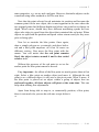
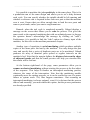
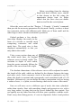
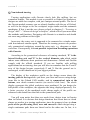
Note: Galaad’s orientation system defines as "west" / "east" the negative
(towards the left) / positive (towards the right) X directions; "south" / "north"
the negative (towards the foreground) / positive (towards the background) Y
directions; and "down" / "up" the negative (towards deep) / positive (towards
retraction) Z directions. This corresponds to the mathematical standard.
This standard orientation remains
valid for machine control. Warning: a
greater value for the depth therefore
corresponds to a lower Z axis towards
negative direction, even if Galaad
reads and displays the depth in
absolute value.
Z
Y
X
You will no doubt have noticed that the dialogue box provides drop down
boxes for setting the origin of the point entered. Therefore it is possible to
define a Cartesian value relative to a point other than the origin of the board,
(0, 0), which is, by default, situated at the south-west corner (bottom left).
Bear in mind that if you enter a dimension that is relative to a given point
located right/above, then it will probably be a negative value.
Returning to our cursor, you will now see it has been fixed at the point
defined in the dialogue box and that the mouse click has been applied. You
now know how to fix something at any absolute position using Cartesian coordinates.
To enter a value in polar coordinates (for the second point
only), you must press
simultaneously.
This will open a similar dialogue
box, but for co-ordinates in the form
(R,? ) as opposed to (X,Y).
2 - 28 —
Learning to design
— — — — — — — — — — — — — — — — — — — — —
— — — — — — — — — — — — — — — — — — — — — — — — — — — — —
GALAAD
3
As for Cartesian co-ordinates, the numerical values of the current position
of the cursor are shown when the dialogue box is first opened.
At this stage of the apprenticeship, you know how to use the design cursor
and define points numerically. Practice drawing by using some of the other
design icons, for example rectangles and circles. However, don't spend too
long at this early stage and stick to the white design icons as the others
(yellow, green and blue) are not directly involved with the drawing process as
you will see a little later.
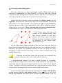
Snapping to positions
If you already have something visible on the board,
perhaps a simple line, you will have noticed that
locating the cursor in the neighbourhood of an existing
object pops up a small red point. A short tip about the
logical position will also appear.
By pressing the space bar
on the keyboard, you automatically
snap the cursor to the small red point, i.e. you directly validate the
corresponding position. This is very useful when dealing with a lot of
pointing tasks, particularly on polygon vertices, intersections, arc centres, etc.
If there is no small red point, then the validated point will correspond to the
current cursor position.
Note that the middle button (or wheel button) of a three button mouse has
the same function, rather than requiring a keyboard input even though the
space bar is not too difficult to find. To manage a snap operation that would
correspond to a click using the right mouse button, press simultaneously the
key (Caps Lock). This is also valid for the mouse middle button.
A little bit more complicated, but worth mentioning,
you may manage a two-stroke snapping, i.e. snap to the
X co-ordinate of a small red point then move somewhere
else on the board to snap another Y co-ordinate or the coordinate of the current cursor position.
— — — — — — — — — — — — — — — — — — — — —
Learning to design
—
2 - 29
GALAAD
3 —————————————————————————————
You only have to locate the cursor close to the first concerned point so that
it is highlighted, then press the
or
key to temporarily store the X or
Y co-ordinate. A vertical or horizontal red axis appears across the board, but
nothing is stored at this moment. You may redo the same operation using the
same key to validate another point in case of error, or even cancel it by
making an ordinary point. Move the cursor and highlight a new red point at
another location and press the other
or
key, the one you have not used
yet. Galaad will automatically validate the position of the point that
corresponds to this couple of X and Y co-ordinates that were temporarily
stored.
Handling objects
Let us stop scribbling now and see what can be done with objects that have
been previously created.
Move the cursor to the left and click on the yellow selection icon,
ignoring the others that fly-out.
The cursor returns to a white arrow and the last object
drawn is framed by a matrix of eight red blocks. Try clicking
on other objects here and there on the board: the red frame
moves from one to another, the outline of the object also turns
red for ease of identification. The design item within the red
frame is then said to be a selected object, an expression
which will be used very often in this manual.
This point is fundamental. With Galaad it is necessary to first select an
object and then specify the action that will be applied to it. With some other
CAD software, exactly the opposite is true, and the action is specified first,
then the target object must be pointed. Each approach has its advantages and
disadvantages, which we are not going to discuss here. If you are already
familiar with a method, let us hope it is the same.
An object is not modified by being selected, though its colour
temporarily changes to enhance it. But it is possible to manipulate it with the
help of the numerous tools that Galaad offers. Let the fun begin.
2 - 30 —
Learning to design
— — — — — — — — — — — — — — — — — — — — —
— — — — — — — — — — — — — — — — — — — — — — — — — — — — —
GALAAD
3
The first and most obvious thing that can be done to a selected object is to
delete it. What could be easier? Press the
key or call "Edit / Delete". The
object and the selection matrix disappear. You can undo this deletion using
the
key (Backspace) that is generally located just above the
key on
an ordinary keyboard, or by calling "Edit / Undo" or the corresponding icon of
the top toolbar.
The second and no less obvious thing is that the object can be
repositioned at another location. Simply move the cursor to inside the
selection frame, click and hold down the left mouse button and move the
mouse. The selection frame follows your movements, and so does the selected
object itself if your computer is fast enough. Release the mouse button to place
the object in a new position. The crosshairs show the position on the rulers
and the co-ordinates in the display zone are updated during this operation.
on the keyboard to move the
You may still use the arrow keys
frame by steps of one unit on the rulers.
Now try clicking on one of the red median blocks of the selection frame
with the left mouse button and whilst keeping it held down, move the cursor
then release the mouse button. The frame is either enlarged or reduced in size,
depending on the movement, and the dimensions of the object are also
changed similarly. When using the diagonal blocks you will see that all the
dimensions change but the aspect ratio is maintained. This allows you to vary
the size of an object without changing its general appearance.
Snapping to positions (bis repetita): when you move, enlarge or reduce a
selected object, the presence of another object in the vicinity shows orange
axes for Cartesian alignment, near its borders or centre. To automatically
align the selected object on an orange axis, just press the
bar on
the keyboard without releasing the mouse button. The
or
keys make a
partial snap so you may align only one axis when both are displayed. Once an
axis has been snapped, the object moves only along the other axis until you
release the mouse or snap to another position.
You will no doubt remember that the
key opens a dialogue box to
allow a position to be defined from the keyboard. This little feature is also
available for all design and object manipulation functions in Galaad. Now
press the
key.
— — — — — — — — — — — — — — — — — — — — —
Learning to design
—
2 - 31
GALAAD
3 —————————————————————————————
This time a different dialogue
box appears in the middle of the
screen. You can define the
position of your object in the
upper part and its size in the
lower part. By default the XY
position of your object, shown in
the dialogue box, refers to the
south-west corner of the selection
frame, but you can also use any of
the other reference points by
clicking on the red blocks.
You will quickly realise that Galaad does not really like it if your objects
extend beyond the edge of the board, especially when entering a co-ordinate
from the keyboard. Since your board represents the raw material to be
machined, it seems somewhat logical that creating toolpaths outside of this
workpiece makes no sense.
At this stage of the proceedings, you know how to draw basic objects,
snap to existing points, enter dimensions for their positions, select objects,
delete and manipulate them.
Now we are going to select several objects simultaneously so that they can
be manipulated as a group. There are several ways of doing this. The first
consists of clicking on our selection icon (if the cross hair design is currently
showing) then defining a rectangular area of the board. To use this method,
press and hold down the left mouse button, drag the cursor a little way and
release the button. The red selection frame surrounds the area covered and all
the objects within the area are now selected. If you only caught one or none at
all, try again. You now have several objects selected that can be manipulated
as if they were one: position, size, delete, etc.
Another way is to start by selecting one or more objects, then press and
on the keyboard and select some other objects. Unlike earlier,
hold down
the new objects are selected without deselecting the ones already selected.
You can continue like this until all objects are selected, including selections
from zones.
2 - 32 —
Learning to design
— — — — — — — — — — — — — — — — — — — — —
— — — — — — — — — — — — — — — — — — — — — — — — — — — — —
GALAAD
3
The magnetic grid
As you will certainly have noticed, both the design cursor and selected
objects can only be moved in discrete steps that correspond to the graduations
of the rulers along the edges. This is a common feature of vector design
software, which provides a grid of invisible points that are not linked to the
graphical resolution of the display and cannot be addressed directly by pixel
co-ordinates. Although this grid is invisible, its influence on the drawing is no
less effective.
The default value for the graduation is one unit of the rulers. At first sight
it may appear that it is not possible to construct or position the design cursor
or an object anywhere other than on a grid point. However, please note that
numerical values entered from the keyboard are not affected by the grid.
The smallest step is 1/1000th, which should be sufficient for most needs.
Galaad considers that if you have entered a numerical value for a position,
then that is where you wish that point to be and the magnetic grid is not
applied, hence it is possible to select any position on the board even when the
grid is active. This entered position remains unchanged.
If entering a numerical position is not suitable for a particular situation,
then simply change the grid step size by using the function "Design /
Magnetic Grid / Set" from the menu bar.
A small dialogue box allows you to
independently set the X & Y steps, i.e. the
values to which positions are rounded up/down.
If you leave a value empty (or "auto"), the
rounding will be to the smallest graduation on
the ruler that varies with the zoom. This is
probably the best mode of operation because
you can zoom in/out and stop worrying about
the grid.
The polar grid rounds the slope angle of the line that is currently under
construction, when pressing
. You can also completely deactivate the grid
and work directly at a pixel resolution, but this is not recommended for
precision work. This grid is there for your convenience and using it will
certainly make life easier. Help yourself.
— — — — — — — — — — — — — — — — — — — — —
Learning to design
—
2 - 33
GALAAD
3 —————————————————————————————
De profundis
Your artistic creations must not be made without forgetting that the
ultimate aim, even if a long way away, is for Galaad to drive a CNC milling
machine. This naturally requires additional information, namely the
machining depth, feed rate and details of the cutter tool to be used. Those
three define the extra dimensions Galaad needs to manage, compared to a
classical 2-D CAD system that is presumed to talk to a printer. They are all
reachable simultaneously.
Click on the green icon on the left of the board, again without
worrying about the other fly-out icons.
A new dialogue box will then pop
up, which will let you enter the milling
depth for the objects that will be
designed hereafter, along with their
feed speed, and finally the cutter tool
that will be used to manufacture them.
Enter a new machining depth for
your chosen objects. Note that you can
select the "Cut out" option to link
depth to actual board thickness.
Further options are also accessible
from this dialogue box.
If you are not familiar with calculating feed speeds then let Galaad do it
for you automatically. By default the software calculates an approximate value
and takes into account the hardness of the workpiece, the physical
characteristics of the cutter and the depth of each pass. Over time you will
gradually learn to estimate feed speeds without running the risk of breaking
cutters, often caused by going too fast. You will soon develop a feel for the
correct values required. Conversion of the entered feed speed to classical units
like m/min or mm/s is displayed below. This may help you feel comfortable
with both these units which are the most commonly used.
When you are ready, click on OK with the mouse (or press
), the
values are immediately applied to the selected objects and the new
characteristics indicated in the display area at the bottom of the screen. If no
2 - 34 —
Learning to design
— — — — — — — — — — — — — — — — — — — — —
— — — — — — — — — — — — — — — — — — — — — — — — — — — — —
GALAAD
3
objects are selected, the new values are not lost, but become the new default
values that will be applied to the next and all subsequent objects drawn, that
is until it is changed again.
Important note: You can have as many depths and speeds as there are
objects on the board. These two parameters are completely independent of
each other and are not connected with either a cutter or a machining pass, as
with many other 2-D CAD/CAM software. In addition, you can have as many
objects on the board as you like, limited only by the memory installed in your
PC, which can be huge. With modern PC's the practical limit is likely to be
your creativity. Remember that you can also draw objects in 3-D with variable
depths as we will soon see.
You now know how to draw objects, reposition them, enlarge/reduce
them, and finally precisely define their milling parameters. So you are ready
to use the milling machine that has been impatiently fidgeting and pulling on
its cable. One last effort, a minor detour via the zoom, and we will be there.
— — — — — — — — — — — — — — — — — — — — —
Learning to design
—
2 - 35
GALAAD
3 —————————————————————————————
Zoom
It is useful to be able to enlarge part of the board to check or adjust the
objects, or even use a smaller step of the magnetic grid when in automatic
stepping mode. This family of functions is designed to help here. For now we
will limit our review to the first two of them.
This should be very familiar from other Windows software, so
simply try it.
You can now define an area of the board to enlarge, or a simple point,
around which Galaad will apply a magnification factor of 2. In the latter case
it is sufficient to click and release on the same point.
To return to a view of all the board (no zoom) select the first flyout icon, "Global View".
Very useful tip: it is possible to perform a fast zoom using the
(or )
key. Galaad will automatically enlarge the zone around the mouse cursor
without aborting the design operation that is in progress. This can be
reiterated, and you can zoom out using
(or ). If you have a wheel mouse
and have installed the driver that is provided with it, a backward or forward
rotation of the mouse wheel calls the same zoom functions without touching
the keyboard. This is often helpful to ease snap operations in crowded zones:
several fast zooms magnify the location where a snap point is available, the
snap is performed then a zoom out is made if necessary to enter the next point
of the object under construction.
2 - 36 —
Learning to design
— — — — — — — — — — — — — — — — — — — — —
— — — — — — — — — — — — — — — — — — — — — — — — — — — — — — — — — —
3
— — — — — — —
0 0 0 1 1
LEARNING TO MILL
— — — — — — — — — — — — — — — — — — — — — — — — — — — — — — — — — —
GALAAD
3 —————————————————————————————
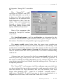
Technical control
Before setting fire to your mill, it may be worth casting an eye over the
settings within Galaad. There will inevitably be some misunderstandings, for
example, in cases where parameters are out of range. Proceed immediately to
the menu, do not pass Go, do not collect £200, and select the function
"Parameters / Machine / Basic data". This should open a dialogue box for a
model which displays a summary of the key technical characteristics of your
machine.
If all is well, you will
find that these are the same
as you used when defining
the CNC during the installation of Galaad.
If this is not the case,
then it is not too late to
change any of the parameters displayed.
It is assumed that you know the model of your machine, or at least the type
of controller it uses. If not, then it is time to contact your distributor after first
of all carefully checking that the model number is not marked somewhere,
possibly in the most inaccessible of places. Entering the wrong machine
type is not a serious problem. Neither your machine nor your computer will
be damaged. In the worst case, it will not respond and simply ignore you. If in
doubt give it a try. Have the courage to try, always have courage!
An important detail, you have probably already installed a cable between
your computer and your CNC. If not, Galaad could find it difficult to control
the CNC. Progress in wireless information technology is certainly rapid, but it
is unfortunately still necessary to have physical connection between most
machines and Galaad.
Whilst on the subject, certain machines require a special asymmetrical
cable (with hardware handshake loops at machine end) of which the correct
end must be connected to the PC and the other to the machine.
3 - 38 —
Learning to mill
— — — — — — — — — — — — — — — — — — — — — —
— — — — — — — — — — — — — — — — — — — — — — — — — — — — —
GALAAD
3
To send information to this cable, Galaad must at least know which
communication port to use. Most CNCs receive their instructions down a
serial RS-232 cable, direct or USB virtual, but not all. It is important to tell
the software to which port the RS-232 cable is connected. Usually the
machine is connected on COM1 or COM2 serial port. However, take care as
this is subject to seasonal variations and the whim of the installer. All
variations are found, but generally the tendency is to put the CNC on COM1.
If in doubt try this way first and if it does not work try putting it on COM2,
etc. If you have a USB-to-Serial converter, it can appear below in the list, for
example COM3, COM4, COM5, or COM6. It is up to you to try, and remember
that trying won’t cause collateral damage to the computer nor installed
applications, even those already running.
You will notice that the dialogue box for configuring the machine
connection allows you to tinker with the baudrate of the connection. If you
have chosen an existing model from the list of known machines, it is best not
to meddle with it. Using a higher communication speed will not make your
CNC run any faster.
Possibly you have no machine connected to your PC. In this case, select
"No machine" as model number and "None" as communication port. The
machine will be virtual but you can follow the logical machining process on
the screen all the same.
Validate this dialogue box by clicking on OK if you have changed
anything, otherwise still click OK just in case.
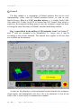
Guided tour of the launch pad
Your board contains the wonders of your creative genius; the parameters
of your machine are correct; the launch window is clear and your seat belt is
fastened. There is no longer any reason to delay the launch. Authorisation for
ignition and blast off is found in "Machine / Mill". Houston, clear for lift off.
A minor digression, check that you have not forgotten to turn your
machine on. The age old adage "it might work better if you turned it on"
sometimes works miracles. Fortunately, polite machines are in the habit of
letting you know when they are powered up. If nothing is illuminated as such,
— — — — — — — — — — — — — — — — — — — — — —
Learning to mill —
3 - 39
GALAAD
3 —————————————————————————————
then you have Galaad's permission to remove your seat belt and investigate.
Incidentally, certain commands also require the drives to be powered and the
safety covers to be closed so check these as well.
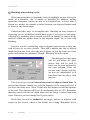
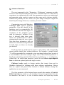
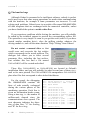
In the meantime Galaad has collected a large amount of information and
displayed it in the dialogue box shown below. Don't panic and do feel free to
experiment, as you cannot do any harm, yet!
At this stage we are not going to examine all the options available in this
window. You will have already noticed that your design is also displayed
here. The only machining parameter that interests us at the moment is the
tool sequence, which is displayed above the design.
If your design has objects that use several different tools, the
corresponding blocks in the tool matrix will be highlighted. In the absence of
any defined sequence the boxes are a uniform yellow and await your selection.
Simply click on the tools required in the order that you wish them to be used.
3 - 40 —
Learning to mill
— — — — — — — — — — — — — — — — — — — — — —
— — — — — — — — — — — — — — — — — — — — — — — — — — — — —
GALAAD
3
When a tool is selected for use it is circled in green and those yet to be
selected have a red cross through them. Once a tool has finished its work, it is
crossed out in yellow.
This notation is important. It is up to you to specify the sequence in
which tools are used and objects machined. In the absence of a user defined
sequence, indicated by all the boxes remaining yellow, the tools will be used
in numerical tool order.
A summary of the tool characteristics is shown below the tool selection
matrix. When the cursor passes over a tool that has been used in your design,
its parameters are shown, whether or not it is selected for use. The rest of the
time it shows the characteristics of the first tool to be used.
It is possible that you have only used one tool. In this case, the tool
sequence cannot be used to control the order in which the objects will be
machined, so move on to the next phase. Mount the appropriate tool into the
spindle and click on the "Workpiece origin" tab, or press
.
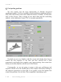
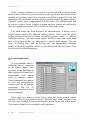
Workpiece origin
The machining parameters page disappears and is replaced by the page for
setting the workpiece origin, which is also packed with control options.
A small message box appears from
nowhere, to remind you which cutter tool is
to be used in the process. Click on OK; you
have no choice.
Communication between your favourite software and your chosen CNC is
opened upon accepting the above message. This initialisation may take
several seconds depending on the machine and if it has just been rudely
awakened.
If this initialisation fails, a small message box will appear informing you
on the nature of the problem. Galaad will spend up to ten seconds trying to
initialise communications with the CNC, and in case of failure offers to retry.
But first of all attempt to establish why it did not work, using the following
— — — — — — — — — — — — — — — — — — — — — —
Learning to mill —
3 - 41
GALAAD
3 —————————————————————————————
check-list: Is it switched on? Is the cable connected correctly between the
computer and CNC? Are the machine parameters set correctly in Galaad?
Assuming that all is well and communications are successfully established
with the CNC, confirmed by a small "beep", Galaad may warn you that it
needs to make the machine perform a short reference run so as to find the
zero point, and waits for you to press OK. Returning to the workpiece origin.
It is now necessary to tell Galaad where to find the workpiece on the bed
of the machine. You can see it, certainly, but Galaad can't. It only knows the
dimensions and the toolpaths that it must follow. Therefore we must give it a
reference point (x,y,z) and tell it precisely where to find the workpiece in
relation to this point.
In fact, don't forget to mount the workpiece, but if you just want to have a
dummy run without breaking anything, that is fine.
3 - 42 —
Learning to mill
— — — — — — — — — — — — — — — — — — — — — —
— — — — — — — — — — — — — — — — — — — — — — — — — — — — —
GALAAD
3
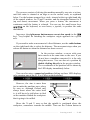
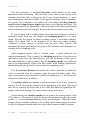
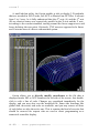
The process consists of driving the machine manually, one axis at a time,
until the cutter is situated at an edge or on the surface work, as explained
below. Use the buttons arranged in a circle, situated at the top right-hand side
of the control window, for X and Y motion, and the triangular buttons for Z
(up and down) movement. When you press a button, the movement is
continuous until the button is released. You can use the small arrow keys
on the keyboard, or even better, a joystick, to produce the same
movements.
Important: the right mouse button moves axes at slow speed (or the
key). Very helpful for finishing the workpiece origin approach on a given
axis.
If you need to make a movement of a fixed distance, use the radio-buttons
on the right-hand side to select the distance. The movement stops when you
release the button or when the distance has been covered.
In the preview window, a cursor with cross
hairs moves at the same time as the axes. If you
do not have a machine connected, it is the only
thing that moves. You can also set a position by
double clicking directly in the preview window.
The co-ordinates of the position will be shown by
the LED display immediately below.
You can also enter a numerical position clicking on these LED displays,
or by pressing one of the X, Y or Z keys on the keyboard.
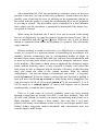
However, the aim is more than
just to make the machine move along
its axes as, although Galaad may
always know where the cutter head
is, it still has to be told where to find
on the machine flatbed the workpiece
that is going to be milled.
Z
Y
X
Move the X and Y axes so that the spindle is positioned above the
workpiece, somewhere towards the middle. Then use the Z-down button to
— — — — — — — — — — — — — — — — — — — — — —
Learning to mill —
3 - 43
GALAAD
3 —————————————————————————————
lower the cutter until it is a small distance above the surface of the workpiece,
say 1 or 2 mm. Go slowly, cutters are expensive and accidents easily happen.
Next, use the right mouse button or select the radio button for 1/10th mm steps
and carefully lower the cutter to the position where it is just gently touching
the top surface of the workpiece, but not actually cutting into it.
You have now found the Z value of the workpiece origin. Click on the
green
button to validate the Z position.
The Z position is then uploaded to
the workpiece origin box.
Now reselect continuous movement and lift the cutter a small amount,
then drive the cutter to the left side (west) of the workpiece.
When close to the edge reset the step size to 1/10th mm, or use
slow motion with the right mouse button, and carefully position the
cutter so that the point is directly above the edge of the workpiece. It
often helps to lower the cutter to improve accuracy.
If using a cylindrical or hemispherical cutter, it is easier to find
the edge of the workpiece with the side of the tool. Galaad knows the
diameter of the tool and can automatically correct the position.
In the latter case, don't forget to select the option "Tool edge" instead of
"Tool centre", situated just above the large yellow start button. Galaad needs
to know which method to use in order to make the correct adjustment.
You have now found the X value of the workpiece origin. Click on the
green
button to confirm that this position is correct.
Finally, repeat the above operation but for the Y-axis, and using the south
edge of the workpiece, again confirming the position with the appropriate
button. With a conical cutter, it is possible to save time and find the X and Y
positions simultaneously at the south west corner of the work, then confirm
both positions simultaneously. It is possible to do all three axes together, but
it is recommended that the Z-axis is set towards the middle of the work
rather than at a corner, as it is more accurate.
3 - 44 —
Learning to mill
— — — — — — — — — — — — — — — — — — — — — —
— — — — — — — — — — — — — — — — — — — — — — — — — — — — —
GALAAD
3
Without going into detail, note that you can also
use several other positions on the board, besides the
south west, for the reference point. Simply tell
Galaad by selecting one from the combo box above
the yellow start button.
When you confirm the position of the workpiece origin, Galaad will then
know the co-ordinates and therefore the position of the origin, but it is still
necessary to tell Galaad where this is in relation to the workpiece, e.g. at the
south west corner. Generally either the south west or the north west corners
are used, but there may be times when another position would be more
appropriate. The important point is that the origin used when designing is
consistent with the origin set on the machine.
Blast off
The workpiece origin has been set for all
three axes. Galaad now knows all that it needs to
know; namely where to find the origin and where
to find the material in relation to that point.
Fasten your seat belt, lift-off is imminent. Now
you can click on the big yellow button labelled
"Start Machining", the one you’ve been itching to
press for ages.
The cutter is retracted if it is low, and
one last message warns you that machining
is about to start. This is your last chance to
chicken out.
Pressing OK starts the automatic machining process straight away. If
your spindle does not start automatically, now would be a good time to switch
it on and set the required rotation speed.
Immediately, the tool moves towards the starting point of the first object to
be machined, rapids down to just above the surface of the work, then reduces
speed and plunges in before making the horizontal moves. When this object is
finished the cutter is retracted to just above the surface then moves on to the
— — — — — — — — — — — — — — — — — — — — — —
Learning to mill —
3 - 45
GALAAD
3 —————————————————————————————
next object where the process is repeated. By default the objects are machined
in the sequence in which they were drawn, but there are plenty of ways of
tinkering with the order.
Several small buttons at the bottom of the window allow you to override
the Z position or the feed speed in increments.
When the machining cycle is finished,
Galaad stops the spindle and returns it to its park
position. The workpiece can then be removed
from its fixings, unless there are other cutters yet
to be used.
Your piece is machined, and you now know how to do it.
You can return to the other parameters and advanced
machining functions later. For now we have covered the
essential points of the process.
3 - 46 —
Learning to mill
— — — — — — — — — — — — — — — — — — — — — —
— — — — — — — — — — — — — — — — — — — — — — — — — — — — — — — — — —
4
— — — — — — —
0 0 1 0 0
LEARNING TO SAVE FILES
— — — — — — — — — — — — — — — — — — — — — — — — — — — — — — — — — —
GALAAD
3 —————————————————————————————
Current design
Before moving on to more elaborate creations, temporarily quit Galaad.
Click on the window close button or use the command "File / Exit Galaad".
Galaad quickly shuts down, this software certainly knows who’s in charge
here.
Now restart Galaad by double clicking on the icon on the desktop or from
the Start menu, by using "Start > Programs > Galaad". After using Galaad a
few times you will soon realise that when it starts it restores itself to the same
workspace conditions that existed when it was last closed, with exactly the
same drawing on the board. This is a peculiarity of Galaad that allows it to
be closed without first asking you so save your current work. You can
therefore work on the same design many times before having to save it.
On the other hand, if you call for a new file
or open an existing one, you will be given the
option of saving the current design first or risk
losing it forever.
If due to principle, habit, shared resources or some other reason you are
unhappy with the automatic save feature, you can disable it using the menu
function "Parameters / Workspace / Advanced". The choice is yours, but
remember that it is activated by default when Galaad is first installed.
Note that both the automatic save on exit and timed backup during normal
work, set in "Parameters / Auto-save", are stored as part of the working
environment and not in a named Galaad design file. If Galaad is shared
between several users (multiple session) then this saving should be directed to
a named file to prevent conflicts in the working environment.
In addition, double clicking on a GAL file will automatically start Galaad
and load the file. However, if the "current design" has not yet been saved
Galaad will give you the opportunity to save this file before proceeding.
Therefore you can fearlessly double click on any GAL file that appears in
Windows Explorer. This is, without doubt, a very useful feature and well
worth mentioning.
4 - 48 —
Learning to save files
— — — — — — — — — — — — — — — — — — — —
— — — — — — — — — — — — — — — — — — — — — — — — — — — — —
GALAAD
3
Files and folders
A complete installation of Galaad, complete with all the examples, is
spread across several folders. Organising the folders in the directory tree on
your hard disk into a clear logical structure is a good way to ensure that your
files will be easily found in the future. This is preferable to simply saving your
files onto your hard disk, haphazardly, like throwing old clothes into a
drawer. Both Windows Explorer and Galaad provide tools to help you
organise file storage. When opening a file the dialogue box will also let you
delete and rename both files and folders at will.
As far as Galaad is concerned, it suggests that you save your designs in a
sub-folder, FILES, in the installation folder, which already contains several
sub-folders of examples. Without doubt the best thing is to follow this lead,
also placing your design folders in this FILES sub-folder, that way they will
appear at the same tree level as installed samples. Thus, Galaad does not
impose any disk management model, the location of your folders and files
remains your choice. Galaad is polite and will always send the file selection
box into the last disk and directory location you used, to avoid spending time
climbing up and down the disk tree, be it local or distant. Memorising the last
default location remains valid for most file and libraries functions.
Galaad's "File / New folder" function prevents you from having to leave
Galaad to use Windows Explorer to create new folders.
You are asked to provide a
name for the new folder. This
will then be added into the list
of available folders. You can
also, if you wish, choose a different path for it.
There remains nothing more for you to do than to save your future designs
into this folder, whose name will now appear on the list of folders available.
You can create as many folders as you wish, but be sure to arrange them into
some sort of logical order. This is only a tool. To delete a folder, use Windows
Explorer or the "Open" and "Save as… " dialogue boxes that will allow this to
be done by selecting the folder or file then pressing the
key.
— — — — — — — — — — — — — — — — — — — —
Learning to save files
—
4 - 49
GALAAD
3 —————————————————————————————
Note: Windows NTFS and FAT32 file systems allow Galaad to use long
file names. This allows you to save your files with long names and with
characters that were previously prohibited by earlier versions of Windows and
DOS, so don't restrict yourself to old DOS filenames.
4 - 50 —
Learning to save files
— — — — — — — — — — — — — — — — — — — —
— — — — — — — — — — — — — — — — — — — — — — — — — — — — — — — — — —
5
— — — — — — —
0 0 1 0 1
ADVANCED DESIGN
TECHNIQUES
— — — — — — — — — — — — — — — — — — — — — — — — — — — — — — — — — —
GALAAD
3 —————————————————————————————
This chapter is intended to introduce you to the subtleties of Galaad's
advanced drawing techniques. It is recommended that all users, even
experienced ones, read the chapter covering the basics before proceeding any
further as it contains several useful tips that are often overlooked.
Numerical co-ordinates
An important feature when designing parts that are to be manufactured is
the ability to specify numerical positions and dimensions accurately. You will
not have forgotten that pressing the
key opens a dialogue box that allows
the position of the cursor to be set without being affected by the current
magnetic grid.
Small tip, by the way: You may enter any numerical value using a
mathematical expression, e.g. a chain of dimensions 12+31.2+4*6.35
written like this in its edit zone. Hence you do not need to search for
Windows’ calculator and copy/paste your result in an edit zone. This subtle
facility applies to any numerical value you have to type. Please refer to the
chapter "Special functions" hereafter, for the syntax and the function
identifiers that Galaad maths formula analyser can understand.
Now imagine that we wish to construct a rectangle, 65.4 ? 32.1 mm, with
the south-west corner at (12.3, 45.6) mm. The first point is easy, simply press
key and type in the co-ordinates. The second point is slightly more
the
difficult as we need to calculate the co-ordinates of the corner diagonally
opposite by adding the dimensions to the co-ordinates of the point already
entered. Galaad provides access to the Windows calculator, but should do this
menial work for you.
This example of a simple rectangle was perhaps not a good choice as it is
possible to position the second point using relative dimensions in two ways.
Firstly by using polar co-ordinates and secondly by drawing the rectangle in
roughly the correct place, then selecting it and numerically modifying the
dimension of the selection frame. The effort remains minimal, but all the
same there is room for improvement and there is a better way. Try the
following: construct a rectangle by entering the first point whichever way you
like (with the mouse or numerically) then press the
key to position the
second point.
5 - 52 —
Advanced design techniques
— — — — — — — — — — — — — — — — — —
— — — — — — — — — — — — — — — — — — — — — — — — — — — — —
GALAAD
3
Instead of displaying a dialogue box for
the co-ordinates of the second point, Galaad
will have anticipated what you intended to do
and provides a dialogue box to input the
rectangle size directly. Simply enter the width
and height of the rectangle.
Actually Galaad follows your work and attempts to anticipate your
requirements, frequently offering context sensitive responses. Consequently,
on constructing a rectangle, after entering the position of the first corner,
there is a strong probability that you would prefer to enter the actual
dimensions of the rectangle rather than the absolute co-ordinates of the
second point. Likewise, when constructing other shapes, such as a horizontal
line or a circle, Galaad will try to pop-up a dialogue box that looks
appropriate to the occasion.
However, if you still wish to enter the numerical position of the pointer
and nothing else, then simply use the
combination which will popup the ordinary dialogue box for a classical XY position.
Partial constructions
Constructing a complex geometric figure usually requires several stages.
These stages are different in the case of a figure that is constructed
progressively, such as an ellipse. First the base is defined and then the form is
added to produce the final result.
It may be that you need to interrupt the construction process before the
final stages, quite simply because the shape that you are constructing only
requires the basic part of the icon’s full function. Take, for example, an open
elliptical arc starting from a centre point, which has four distinct stages and
requires the following data: firstly the centre point; secondly the major and
minor Cartesian radii (X and Y); thirdly, the starting angular point of the arc
and fourthly the angular end point of the arc. The result should look like an
elliptical arc.
— — — — — — — — — — — — — — — — — —
Advanced design techniques —
5 - 53
GALAAD
3 —————————————————————————————
Now imagine that you wish to construct a centred full
ellipse (i.e. completely closed). There is not a design icon
specifically for this simpler construction, so steps 3 and 4
of the above process will have to be skipped. Consequently
we need to interrupt the construction without losing what
has already been drawn and without aborting the whole
process.
Furthermore, certain design functions in Galaad are repetitive and have no
definite last stage. The simplest example is a polyline, which requires a start
point then an indefinite series of additional points. It is up to you to decide
which point will be the last. When each new point is clicked, the software
adds it to the polyline and awaits the next point, until you decide to indicate
the final point by clicking with the right mouse button. There are other
repetitive figures that follow this pattern, such as Beta-Splines (which have a
maximum number of 256 nodes) and Bézier curves which have no such limits
on their nodes.
Remember then that entering the last point of any "repetitive" construction is simply a case of clicking with the right mouse button.
This is also true for shapes drawn using a "progressive" construction
technique. If you wish to stop drawing a given construction before its last
stage, use the right mouse button as in the following example.
In the case of a closed ellipse it is simply a question
of fixing the X and Y radii with the right mouse button,
which terminates the construction process there. Note
that the start and end points will be at the standard
trigonometric zero position, i.e. at 3 o'clock.
It is also possible to stop the process one step further
on which will allow the start and end points to set at
any angle required.
The construction of other shapes also works in a similar fashion, for
example, a star (before defining the internal circle), radii (before the internal
circle and angular spacing) or a spiral (before the internal circle).
5 - 54 —
Advanced design techniques
— — — — — — — — — — — — — — — — — —
— — — — — — — — — — — — — — — — — — — — — — — — — — — — —
GALAAD
3
In any case, please remember that you can end the construction of a shape
at anytime, without losing what has already been drawn, simply by clicking
with the right mouse button to indicate the last stage.
Editing object geometry
Nobody is perfect and sooner or later you will find that you will need to
modify a design without starting from scratch. A typical example is a Bézier
curve where the positioning of a node has an effect on the previous one and
depends on the distance between them. Almost certainly there will be times
when the result is not quite what you had imagined and you will wish to make
adjustments to obtain the desired shape.
Four types of object retain the ability to be edited geometrically: arcs (of
circles or ellipses), Beta-Splines, Quadra-Splines and Bézier curves. The
last three still show their nodes after being constructed and can be edited
immediately, however, this does not mean that they cannot also be edited at a
later date. Arcs do not show these straight after construction, but can
nevertheless be edited later on.
Construct an arc or an ellipse, either open or closed,
using the appropriate design icon of your choice. Then
key or select the object to leave the
press either the
design mode. Now click inside the shape with the right
mouse button and a special edit frame will appear around
the object.
Note that the mouse double-click does the same if the object below the
mouse is alone. You can then modify the shape by moving the red blocks, this
allows the centre, radii, start and end points to be edited. Alternatively, you
can press the
key to open a dialogue box and access the parameters
numerically. When you are finished select another object or simply press the
good old
key.
Note, that in the case of Beta-Splines you can vary the "attraction" of any
node by simply pressing the
or
keys. Use the
key to move between
them.
— — — — — — — — — — — — — — — — — —
Advanced design techniques —
5 - 55
GALAAD
3 —————————————————————————————
For other objects, that are not editable in this way, clicking with the right
mouse button will select a segment or a point. See the specific paragraph on
this feature.
Locking objects
This old but nonetheless useful function allows objects to remain visible
without being selected and hence not changed in any way. Simply select an
object - one last time - and click on the locking icon, shown below.
Once locked, an object cannot be selected, nor can any part of
its composition.
This is particularly useful when you wish to work on a group of objects
without affecting others that are within the same area. The locked objects
remain visible (displayed in pink) and will be machined in the normal way,
but cannot be selected. Note that there is a keyboard shortcut that uses the
combination of the
and
keys (you will need to reset the Caps Lock).
To unlock objects it is necessary to use the menu command "Edit /
Unlock" and either unlock all of them or simply select them with the mouse.
You can also reuse the same locking icon if no object is currently selected,
Galaad should understand that you want to unlock something instead.
Associating objects
Another classic selection feature is the ability to group some of the objects
together then treat them as though they were a single entity. One for all and
all for one.
This function can be found, quite logically, amongst the other
selection icons.
5 - 56 —
Advanced design techniques
— — — — — — — — — — — — — — — — — —
— — — — — — — — — — — — — — — — — — — — — — — — — — — — —
GALAAD
3
Draw several objects and select them all, then click on this icon.
Henceforth, they will act as a single object and selecting any object of the
group will also select all the others. Note that text blocks use a different
system in order to maintain character spacing. However, text blocks can be
associated with other text blocks and also non-text objects.
To break the association it is necessary to use the menu command "Edit /
Ungroup" which provides a range of self-explanatory methods. If no object is
currently selected, the association icon switches to the reverse operation and
lets you point to the targets. Finally if all selected objects are already
associated, then clicking on the icon breaks the whole community.
Protecting objects
It can sometimes be useful to provide an object with a limited degree of
protection, to avoid leaving it alone on the torture table but still keeping it
available for selection and position.
The protection function, with its little shield, allows only limited
operations to be performed.
This feature prevents an object from being deleted or subject to any
manipulation other than being moved or re-scaled, neither of which actually
change the basic shape. Galaad considers that these operations do not alter the
actual geometry of the path and therefore allows them. On the other hand, the
path can neither be cut, incised, reshaped, nor have additional segments
welded to it.
To unprotect an object use the menu command "Edit / Unprotect" or click
once more on the icon. Note that protected items can be identified on the
board with a small shield located near to their start point, by using the menu
command " Display / Trace / Protection".
— — — — — — — — — — — — — — — — — —
Advanced design techniques —
5 - 57
GALAAD
3 —————————————————————————————
Anchoring objects
Inevitably there will be times when, in order to position them, it is not
very convenient to create a group of associated objects. Conversely there may
be times when you wish to fix an object to an absolute position even though it
belongs to a group and the others are to be moved.
Consequently, Galaad provides two adaptable methods for this.
The absolute position of an object on the board can be fixed or
alternatively, the position of an object relative to other objects can
be fixed, without creating an association.
The absolute anchoring of an object freezes its position and prevents any
further attempts to move it. Draw two objects and anchor one in position, then
select both objects and move them both. Still selected, the anchored one will
not want to move; this is very irritating.
Anchoring objects relative to each other is less restrictive. The position of
each object can be changed, but moving one object will result in all objects
anchored to it being moved by an equal amount. Draw three objects, select
them and anchor them relatively to each other. Now select only one of them
and move it, the others will also move by the same amount, even though they
were not selected.
As well as its practical use for positioning a group of objects, the relative
anchoring function has some interesting side effects that will be of interest
later on, when we look at the selection and manipulation of points and
segments.
To release anchored objects it is once again necessary to use the menu,
this time "Edit / Free anchors". As with protected objects, objects anchored in
position can also be identified, this time with a small anchor, by using the
menu command "Display / Trace / Position anchors ". The corresponding icon
can also be used for releasing anchored objects, if none are currently selected.
5 - 58 —
Advanced design techniques
— — — — — — — — — — — — — — — — — —
— — — — — — — — — — — — — — — — — — — — — — — — — — — — —
GALAAD
3
Selecting and handling points
We have seen how to select and handle objects. Whilst this type of
selection is fundamental for using Galaad, it is not the only one. Several
construction and manipulation functions require that one or two points be
selected, so that the position can be reused as a given reference.
Galaad has three distinct selection methods for objects, points and for
segments. Then for each of these three there are two possibilities, selection in
red, which is the main method, with selection in blue as an alternative,
therefore giving a total of six possibilities, each with a different purpose.
What is more, as several of these selections may be present simultaneously,
Galaad shows the "focus" on only one of them at any one time.
This "focus" takes the form of a
contour in the selection frame. Note
that objects selected in red have
priority and always have the focus.
Shifting the focus to another selection
or returning to the design mode
deselects the object.
On the other hand, objects selected in blue can never have the focus as
they cannot be manipulated in any way and only serve as a reference for other
functions, but points and segments selected in blue can have the focus.
Returning to point selection, they help to draw, locate accurately and even
modify trajectories.
Both the red and blue point selection icons can be found in the
group of selection icons. Let us start with the red one.
A straightforward example is to draw a simple polygon or a rectangle.
Click on the icon shown above then on one of the vertices of your shape. For
it to work, the tip of the arrow (cursor) needs to be very close to your chosen
vertex. If all goes well, there should now be a red spot on the vertex with a
ring around it showing that it has been selected and has the focus.
Useful shortcut: instead of using the selection icon, simply click directly
on the vertex with the right mouse button. If the
key is held down
during this operation the point will be selected in blue instead of red. As
— — — — — — — — — — — — — — — — — —
Advanced design techniques —
5 - 59
GALAAD
3 —————————————————————————————
described earlier, clicking on arcs and curves with the right mouse button
allows their geometric features to be edited. It is therefore necessary to press
the
key simultaneously in order to select a red point on one of these
figures (
still being necessary to select a blue point).
How to use a selected point. Select a red point and click on it with the left
mouse button and whilst keeping it held down, drag it to a new position then
release the mouse button. The whole object will also follow to this new
position. Now try the same thing but with the right mouse button, this time
only the point itself is moved, the rest of the object is unaffected.
As you would expect by now these operations can also be performed from
key opens a dialogue box designed
the keyboard. The now familiar
specifically for positioning the selected point, alone or the with the entire
object, this is equivalent to using the right and left mouse buttons. The usual
keys allow the whole object to be moved along with the point and
simultaneously pressing the
key results in only the point being moved.
If a point is selected in red, then pressing the
key will cause the
selection to move on to the next point in the object or the connected objects. If
the
is pressed simultaneously the direction of travel will be reversed.
Using the
key moves immediately to the end point and
to the
start point.
Next feature: with a point selected in red, press the
key. This will
simply delete that point and thus change the shape of the object. The
selection then moves to the preceding point if one exists. This function may
help you practice some surgical strikes on objects.
Slightly more difficult, draw two simple straight lines with an extremity of
one at, or very near, an extremity of the other. They are distinct objects that
can be selected individually. Now select a red point at the ends where they
meet and use the command "Design / Object / Weld " from the menu. Galaad
will join the two objects at the red point to form a new single object, try
selecting one of the original ones. The operation can be reversed by using the
menu command "Design / Object / Split" which will also work on the
intermediate vertices of any polygon. You have two objects again. It goes
without saying that only end points can be welded together and only
intermediate points can be split. Please note that certain objects cannot be
joined in this way and that it is only possible to weld objects that have the
5 - 60 —
Advanced design techniques
— — — — — — — — — — — — — — — — — —
— — — — — — — — — — — — — — — — — — — — — — — — — — — — —
GALAAD
3
same properties, e.g. an arc and a polygon. However, dissimilar objects can be
connected using other methods as will be seen later.
Note that the point selected in red maintains its position and becomes the
common point for the new object, this is most apparent in the case where the
two original points had different depths and where one point has to change its
depth. What's more, should they have different machining speeds the new
object also takes its speed from the object that contained the red point. When
objects are split both the position and speed values return exactly as they were
prior to being split.
Now let us consider the blue points. Once again,
draw a simple polygon or a rectangle, and place both a
red and a blue point anywhere on it but of course on
different vertices. Now move the blue point with the
mouse. You will notice that the red point remains
fixed, the object rotates around it and is also scaled
relative to it.
Without the presence of the red point to act as the
anchor point the blue point cannot be moved.
Very important: the effects of the blue point are much greater than at first
sight. Select a blue point on another object and move it. Although the red
point is on a different object, it still acts as the pivot point. What is more, if
the blue point is placed on an object within a group of objects that are
anchored together, all those objects will pivot at the same time. This can
help when making fine adjustments.
Apart from being able to snap to, or numerically position, a blue point,
there is not much else you can do with one except delete it.
?
— — — — — — — — — — — — — — — — — —
Advanced design techniques —
5 - 61
GALAAD
3 —————————————————————————————
Selecting and handling segments
In the same way as with points, individual segments can also be selected
and have their own special functions, notably for the construction of new lines
based upon them (parallel, perpendicular, etc.). Selected segments are always
orientated, that is to say they have a direction, indicated by a start point and
an arrow head, which helps when entering details numerically. Important
note: the direction of such a selected segment is independent of the
toolpath of which it forms part.
As usual, look in the yellow selection icons to find the segment
selection icons.
As with points, segments can be selected by clicking with the right mouse
button, but this time aiming for the segment away from a vertex. If the
segment is particularly small, simply zoom in a bit. The other features also
key to select a blue segment and the
key triggers
apply, i.e. using the
the selection of segments on objects sensitive to the right button. In fact the
only difference between selecting points and segments is where you aim. If
you are aiming at a point then that is what you will get, otherwise it will be a
segment. All accessories are the same.
As you might have expected, the
key moves between segments in a
forward direction and the addition of the
key reverses the direction.
Adding the
key moves directly to the start or end segments.
Click on one of the extremities of a red segment with the left
mouse button, keep it pressed down then move it. The segment
can be enlarged or reduced, but only along its axis, without
affecting the rest of the object. Both ends of a segment can be
manipulated in the same way.
Now do the same thing with the right mouse button. This
time the segment can be rotated round its other end without
changing its length. Combining the use of both mouse buttons
effectively allows you to change the polar co-ordinates of a
segment.
5 - 62 —
Advanced design techniques
— — — — — — — — — — — — — — — — — —
— — — — — — — — — — — — — — — — — — — — — — — — — — — — —
GALAAD
3
Segments selected in red are used by many of the design icons, notably
when constructing lines, parallels, perpendiculars, intersections and others,
but when it comes to manipulation and adjustments, segments selected in blue
are much more powerful. Now select a segment in blue from a polygon in
your design.
As you can see on the screen, and unlike with a red segment the whole
object is either scaled or rotated around a point when the extremities of a
blue segment are dragged with the mouse, left or right button keeping the
same functions as for handling the red segment, i.e. rotating and stretching.
This may also help you to scale and adjust objects according to a basic pair of
co-ordinates.
Moreover, if other objects are anchored to the one
containing the blue segment being manipulated, then they are
all resized and rotated together, as with blue points. This can
help rotate objects around a pre-set point. Anchor all of the
objects together and to a segment created specifically for the
operation. Select this segment in blue and rotate it
accordingly. Numerical dimensioning using the
key is
essential for an accurate result.
— — — — — — — — — — — — — — — — — —
Advanced design techniques —
5 - 63
GALAAD
3 —————————————————————————————
Moving groups of points
This unique little icon from the selection series is well worth a
passing mention.
This icon allows you to select part(s)
of one or several objects so their
appearance can be changed without
modifying the points one at a time.
First, it is necessary to define a
selection zone and all points within it,
no matter what object they belong to,
will be selected and can then be moved
or scaled, repositioned or stretched
independent of the rest of the design.
Except moving and framing, no operations can be performed on groups of
points. It is not possible to globally delete points that are selected in a group.
Special effects are not available either.
Duplication and cloning
Duplication is a vital feature of design software. Obviously, using the copy
and paste feature will allow a degree of redesigning. However, a special
function is required if multiple copies are to be placed at regular intervals.
Galaad 3 also introduces a new feature, virtual duplication, intended to save
both time and memory usage.
Start as usual by drawing an object. If you copy the object and paste the
copy back onto the board, it will then contain two completely independent
copies of that object. Modifying the original has absolutely no effect on the
copy and vice versa.
Once again select the object, (or the copy if you prefer) and apply the
function "Edit / Duplicate / Add one virtual copy" from the menu. Galaad will
display a selection frame for the copy, to allow you to position it accurately (of
5 - 64 —
Advanced design techniques
— — — — — — — — — — — — — — — — — —
— — — — — — — — — — — — — — — — — — — — — — — — — — — — —
GALAAD
3
course the
key remains available as usual). When you have placed this
copy, try selecting it. As it does not actually exist, it is impossible to select it,
only its image is visible, however, it can still be machined. Don't worry
about it, just because it is virtual it still retains the machining parameters of
the original.
Next select the original object and move it, the
copy also moves by the same amount. Modify the
shape of the original using any function you like,
(there are plenty to try), and the copy takes on the
same shape. If you select a point on the original and
either move or delete it the copy is also changed
accordingly.
In fact, most duplications in Galaad are virtual by default. Also when you
place a series of copies at regular intervals, the copies are all virtual copies
and will therefore be modified at the same time as the original. This is most
useful when modifications have to be made, as only the original needs
changing and all the copies will follow suit.
Having said that, copies do not have to be virtual copies and if you wish,
independent copies can be produced. The dialogue box for duplication gives
you both options. What is more, you can make virtual copies real so that they
become independent objects. The "Edit / Duplicate" menu contains all the
necessary functions to undertake this, but remember that the reverse process is
not possible, real copies cannot be made virtual so you must decide in
advance.
We will not dwell on the simple duplication methods, (in line, in a matrix,
in a circle or special) which can easily be understood by trying them, but
instead move on to the more advanced features.
Mirror duplication makes a copy of the selected object
about a variety of axes of symmetry, leaving the original
object in place. It is even possible to make the duplication
about a red point or a red cross.
As the process produces an inverted copy it cannot be
virtual.
— — — — — — — — — — — — — — — — — —
Advanced design techniques —
5 - 65
GALAAD
3 —————————————————————————————
Duplicating along a blue trace places multiple copies of
an object selected in red, along the length of a trace selected
in blue. Optionally, they can be orientated to lie on the
tangent of the trace, but in this case the copies will not be
identical because they will have rotated so cannot be virtual,
therefore real objects will be produced.
A duplicate trace between points takes the portion of an
object located between a red and a blue point and makes a
single copy of it. Obviously the points must lie on the same
object or path.
Cloning is a less sophisticated function than
duplication that simply produces a single, virtual
copy of the selected object, mirrored in one of the
four quadrants. This can help in constructing
perfectly symmetrical shapes without having to
specifically design the other half. It goes without
saying that the clone is machined in the same way as
the original and inherits the same machining
parameters.
An object clone is always stuck to one Cartesian border, and cannot be
moved any further, which may limit the interest of such a function. You
should weigh up the advantages and disadvantages against those of the mirror
duplication, which does not impose such immediate neighbourhood but on the
other hand makes a real and consequently independent copy. Mirror duplication or cloning, it is up to you to choose the right function.
5 - 66 —
Advanced design techniques
— — — — — — — — — — — — — — — — — —
— — — — — — — — — — — — — — — — — — — — — — — — — — — — —
GALAAD
3
Rapid data palettes
When creating a complex design, it soon becomes difficult to manage the
machining parameters, object by object, using the green icon to access them
one at a time. Therefore Galaad provides a shortcut for this. This function is
very important.
Draw several objects on the board using a variety of depths, feed speeds
and cutters so that they are all different. Now use the menu command
"Display / Data Palette / Machining depths".
A small horizontal line of data blocks will have been added to the display
between the board and the speed buttons. This shows all the machining
depths that you have used with the current default being highlighted by a
green border. When you select an object its depth is highlighted with a red
border. Now click on another depth shown in the data palette and the depth of
selected object will be set to this new value without having to go via the
dialogue box. With two clicks of the mouse you can change any depth to any
other depth currently used in the design. This feature also works with feed
speeds and cutters.
Even better, click on one of the blocks within the data palette with the
right mouse button and keep it pressed. Only objects with that depth remain
visible. Double clicking with the right mouse button selects all these
objects.
To skip from one palette to another, click on the left block that displays
the palette type (tools, depths, etc.) with the left mouse button for next type
and the right mouse button for previous type.
Note that Galaad can display a maximum of ten palette blocks, possibly
only six if your vital space is reduced. On the same lines, only one palette can
be displayed at a time.
— — — — — — — — — — — — — — — — — —
Advanced design techniques —
5 - 67
GALAAD
3 —————————————————————————————
Keyboard shortcuts
We recommend you to print this list out and keep it close to your work
station. Not all key combinations may be of use to you, but the main ones
most certainly will be.
Default:
/
(or
/ ) zooms in around the cursor.
opens a position dialogue box.
opens the dialogue box for depth / feed speed / cutter.
(or
) interrupts the current operation or deselects.
deselects all: objects, points, segments, blue or red.
(backspace) undoes the last operation, including pointing.
redoes the last operation (except pointing).
moves the cursor or selection by one step of the grid.
moves the zoomed view.
/
sets the magnetic grid size 10 times smaller / larger.
sets the magnetic grid size to automatic (ruler divisions).
(tab) skips the selection to the next object, point or segment.
moves from the current selection to the previous one.
refreshes the display.
+ quad view or 3-D view icon shows a rotating 3-D view.
pulls the alarm. Abusers will be fined.
Design mode (cross hair cursor visible):
opens a polar position dialogue box.
snaps to the small red point.
(backspace) cancels the last pointing.
when pointing a line, applies the polar magnetic grid.
With selected objects:
+ mouse select adds to selection.
select all.
/
increases / decreases the depth (0.01 mm by default).
/
sends the object to the first / last place in the sequence.
locks the selected object
inverts the selected object.
inverts the selected object about the X/Y bisector.
/
selects in red the object’s start point / segment.
5 - 68 —
Advanced design techniques
— — — — — — — — — — — — — — — — — —
— — — — — — — — — — — — — — — — — — — — — — — — — — — — —
GALAAD
3
With selected points:
moves only the selected point.
/
increases / decreases the depth (0.1 mm by default).
selects the last point.
selects the first point.
deletes the point.
selects the whole object.
selects the segment starting from this point.
With selected segments:
selects the last segment.
selects the first segment.
deletes the segment.
selects the start point of the segment.
selects the entire object.
When editing arcs:
/
Sets the direction as clockwise / counter-clockwise.
When editing a Beta-Spline:
/
increases / decreases the attractive pull of a node.
deletes the node.
inserts a node.
When editing a Bézier curve:
+ movement of a control point breaks the tangent at the node.
+ movement of a control point locks the angle of the tangent.
deletes a node.
inserts a node.
cuts the curve in two at the highlighted node.
When setting the rotation or inclination of an object:
/
increases / decreases by one degree.
NB! Function keys F1 to F12, alone or combined with
, can be easily
customised and directly associated to menu commands using "Parameters /
Function keys".
— — — — — — — — — — — — — — — — — —
Advanced design techniques —
5 - 69
GALAAD
3 —————————————————————————————
Display functions
A screen filled with objects can be very disconcerting, when all of them
have different and hidden machining characteristics, and having to select
each object in turn to display its depth, feed speed, tool etc. soon becomes very
tedious. Galaad provides alternative ways of displaying this data.
As you may have already noticed, the "Display" menu is hardly the
smallest around and consists of numerous commands buried in an array of
sub-menus. A selection of the most commonly used features is detailed below.
The trace functions change the appearance of drawn objects. This allows
you to make all trajectory points visible, or just limit it to the points on a
toolpath where objects are connected. In addition, a small numerical identifier
can be displayed at the start point of each object, showing the depth, cutter
number, feed speed, etc., as shown below.
For example, you may want to display the depth of an
object at its starting point or all the variations along the
trajectory. The same applies to the feed speed, the cutter and
the machining sequence number of each object.
In addition you can use colour to highlight differences instead of just
having a single colour. Each cutter can have a colour assigned to it and
Galaad can be set to show objects in the colour corresponding to their cutters.
Alternatively Galaad can highlight all objects using the current default
machining parameters (whether this be the cutter, the depth or the feed
speed). In this case, there will only be two distinct colours on the board. For
example, if the display colour is set to "Default tool" then all objects on the
active layer that use the current default cutter will be displayed in black with
all other objects displayed in grey. A black background produces a clearer
distinction as the main traces are then shown in green. You can assign a fixed
colour to any object once and for all. In any case, keep in mind that this has
very little interest for actual millings.
Please also note that selected objects are always displayed in red (or blue),
locked objects in pink, visual (not machined) objects in grey, and tool
compensated paths in dark green. This will remain unchanged unless you
mess with "Parameters / Colours".
5 - 70 —
Advanced design techniques
— — — — — — — — — — — — — — — — — —
— — — — — — — — — — — — — — — — — — — — — — — — — — — — — — — — — —
6
— — — — — — —
0 0 1 1 0
TOOLPATHS
— — — — — — — — — — — — — — — — — — — — — — — — — — — — — — — — — —
GALAAD
3 —————————————————————————————
Tool parameters
Galaad uses a tool library containing up to 50 different cutters. Filling this
library is one of the first jobs that should be done after the software has
been installed. The number and type of cutters will depend on how you
intend using your machine, start by filling it with the cutters that you wish to
use right now and simply leave the rest empty until you wish to add more
tools. What is important is that the tools you actually mount below the spindle
of your machine correspond exactly to those you enter into Galaad's tool
library.
A reliable old method is to lay out your tools in a numbered rack and
ensure that the numbers correspond to those in Galaad's tool library. In this
way, you can rapidly find the references for each tool used and also quickly
lay your hands on the cutter that Galaad asks you to load. Having said that,
you can also add the name of your choice to each cutter, this will be displayed
beside the cutter number. Note that in the library, a tool number can be left
unused, even between two assigned numbers. Tool numbers are simply
identifiers and have no numerical meaning, except for in a sorted listing.
Tool library management relies on two separate commands:
The first one, accessible from "Machine /
Tool library", opens a
passive window that
shows which tools have
been defined and which
tools are actually used in
the current design. Displayed values are readonly.
This window provides an overview of the tool library, with the tools that
will be used for the current workpiece indicated by a tick. Simply click on any
tool number to display a summary of the tool parameters. Access to both
viewing and editing the full details is via the "Parameters" button. Please note
that Galaad allows the use of a tool that has not been defined, but in this
case it will not be possible to calculate any contouring toolpaths or automatic
6 - 72 —
Toolpaths
— — — — — — — — — — — — — — — — — — — — — — — — —
— — — — — — — — — — — — — — — — — — — — — — — — — — — — —
GALAAD
3
feed speeds, and it will be up to you to decide what to mount below the
spindle at the time of machining.
The second command for managing tools gives access to tool definitions.
A given tool is defined when at least its two main parameters have been set,
namely diameter and profile. This is sufficient for Galaad to calculate the
correct compensated toolpath and approach from the workpiece origin, but
this should not prevent you from entering a full description of other physical
properties of a cutter.
The alternate and faster way
to access the details of individual
cutters is via the menu command
"Parameters / Tools". This popsup a dialogue box, which allows
all 50 tools in the library to be
defined one by one simply by
scrolling through the "Tool
number", which can be found in
the top left-hand corner of the
window. When you are happy
with the changes and new tool
definitions, click on OK which
validates all changes including
masked ones, otherwise click on
Cancel to retain the previous
settings.
Note: selecting a tool to modify its parameters will neither change the
default tool nor the tool used by any selected objects. The tool library is
completely independent of any design. The cut depth and feed speed largely
depend upon the physical characteristics of the tool (as well as the hardness of
the material to be cut).
When Galaad is installed, a tool library comprising only one pre-defined
cutter exists. It is likely that your personal collection of cutters will have much
more. Simply change the parameters of this tool and create the others. To
avoid cluttering up the list, you may delete previously created tools that are no
longer of any use to you, by clicking on the "Rubout" button to leave that tool
— — — — — — — — — — — — — — — — — — — — — — — — —
Toolpaths —
6 - 73
GALAAD
3 —————————————————————————————
number empty. Alternatively, if you would like to compact the tool library by
moving all of the tools down by one position click on "Del. <<", or on
"Ins. >>" to insert a tool in the middle of the list. The last button "Delete all"
clears all the following tool numbers in the library after the current one (not
included).
Each cutter can also be given a name and a colour, which is only
displayed if the mode "Display / Colours / Tool dependant" is selected. The
name of the tool appears in the list and is displayed in the message before
setting a workpiece origin. This has no other function than to remind you
which tool this number corresponds to.
The key parameter of any tool is the diameter and leaving it blank tells
Galaad that the tool is not yet defined, consequently there is no point in
entering any of the other information as it will not be stored in the tool library
until a diameter is entered. It is important to be as accurate as possible with
this figure, which should be measured over the largest diameter of the active
cutting part of the tool. If the tool is not cylindrical, for example with a
conical engraving cutter or a 3-D hemispherical cutter, this is frequently the
same as the shank diameter. For a cutter with a special profile, e.g. a surface
mill in reversed "T" or a pyramid tool, the right value will be the maximum
active diameter.
The profile of a cutter, linked with its diameter, determines how the width
of the cut will vary with depth. Profile families are: cylindrical (drilling,
boring, cutting, flat milling), conical (engraving or chamfered cutting),
hemispherical (3-D milling ball-end), pyramidal (reversed conical cutter for
surfacing), and arcade (conical tool with fillet borders). With a cylindrical
tool the width is constant, irrespective of the depth, but with a conical or
hemispherical cutter the width will get wider as the cut depth increases, up to
the maximum diameter that the tool can cut.
With a conical tool it is necessary to accurately specify the
point angle. This angle is the full included angle, measured from
side to side and not the half angle from the centre line. If the two
sides are unequal, measure the largest half angle, then double it as
when the tool rotates about its axis it will describe a cone swept out
by the largest side.
6 - 74 —
Toolpaths
— — — — — — — — — — — — — — — — — — — — — — — — —
— — — — — — — — — — — — — — — — — — — — — — — — — — — — —
GALAAD
3
The automatic calculation of feed speeds is also based on the number of
teeth and the speed of rotation of the cutter, as parameters of secondary
importance. It is true that feed speeds are supposed to be based on these two
factors when cutting metallic components. But the fine tools used in
engraving or for cutting softer material are very fragile and demand that other
factors are of primary importance, namely the tool diameter, profile and cut
depth. Galaad takes this approach in its calculations. The spindle speed is
displayed immediately before machining, and controlled directly from the
software where this is possible, i.e. if a remote speed control is available and
of course correctly parametered from Galaad. See CNC parameters, spindle
section, for more details.
The main parameter that prevents expensive cutters being broken is the
maximum depth per pass, which defines the deepest cut that the tool can
make in any one pass. In the case of a cylindrical cutter, the theoretical depth
is equal to the length of the cutting (fluted) part, but that supposes that the
tool is solid. It is preferable to stick to something a little closer to twice the
diameter of the tool to prevent unwelcome surprises and assorted expletives. If
the tool is conical (engraving javelin) or hemispherical (3-D ball-end), its
maximum depth is simply the height of the cone or the radius of the
hemisphere, assuming that the teeth extend that far.
NB! The maximum cut depth per pass also depends on several other
factors, not least the resistance offered by the material. In addition, it goes
without saying that a new carbide tool will have a much better performance
than an otherwise identical, but well used, HSS tool. The unsupported length
of the cutter, (i.e. that protruding below the collet), must be taken into
account. The longer the length, the slower it should cut to prevent excessive
deflection and a broken cutter. Then there is vibration, directly proportional to
the spindle speed, it can be detrimental to the quality of the finish and fatal to
the cutter. Clearly the less cut depth, the less work the tool has to do removing
— — — — — — — — — — — — — — — — — — — — — — — — —
Toolpaths —
6 - 75
GALAAD
3 —————————————————————————————
material and the less resistance it will feel. Galaad takes this into account
when calculating feed speeds.
Note that Galaad manages increasing depth passes and avoids passing
twice in deep paths that have been already milled during a previous pass. In
the case of 3-D paths, the tool then only does the active part of the trajectory
for the current pass, this also applies for the ending lift-up point. So there no
time is wasted with a tool passing several times in the same final path.
Just below half way down the dialogue box is a section which contains
several parameters applicable to vertical motion only i.e. when a tool is
plunging or drilling into the material. It also covers clearances for drilling
cycles used for clearing material out of deep holes.
The first parameter, the preliminary plotting, forces the tool to drill the
material for a small depth that you can indicate here, with the corresponding
speed. Obviously, the operation is performed only if the path depth is greater
than the plotting depth. This function is useful only with certain tools and
very hard materials.
Next Galaad allows the plunge speed, speed at which the tool cuts
vertically into the material, to be set independently from the horizontal or 3-D
feed speed given to each object. This speed is linked to the characteristics of
the cutter itself and can be set at a fixed value once and for all. Whatever its
design, an engraving cutter does not drill as well as a proper drill bit.
In essence the machining process follows this sequence: the tool moves
horizontally at a safe height above the workpiece and at a rapid speed, V1, to
a position immediately above the start point of the first object to be machined.
It then moves down at a rapid speed, V2, to just above the surface of the work
before plotting at a very slow speed, V3, and entering the material at the
plunge speed, V4. The part is then machined (2-D or 3-D trajectory) at the
feed speed, V5, and finally the tool is retracted vertically at a rapid speed, V6,
to a point above the workpiece. The speeds V1, V2 and V6 are not related to
the workpiece, but depend on the performance of the machine, hence these
parameters can be found in machine parameters. The feed speed, V5, of
each object is determined when it is constructed and the plotting and plunge
speeds, V3 & V4, are set as discussed in this chapter.
6 - 76 —
Toolpaths
— — — — — — — — — — — — — — — — — — — — — — — — —
— — — — — — — — — — — — — — — — — — — — — — — — — — — — —
GALAAD
3
Nevertheless the plunge speed can also be set in the other traditional way,
namely as a percentage of an object's feed speed. In this case you just have
to indicate this ratio in the corresponding edit zone, in percentage of feed
speeds. The two methods are mutually exclusive therefore entering a
percentage value will delete an absolute value and vice versa. At the end of
the day the choice is entirely yours and is likely to be influenced by the type of
work that you undertake. Note that it is only possible to have automatic
plunge speed if the feed speed is set to auto and the plunge speed set to a
percentage of the feed speed.
The deburring cycle is a classic drilling operation, which repetitively
retracts the drill out of the hole after it has cut a predetermined amount, and
returns it back to the depth it has just reached ready to take the next cut. This
cycle is repeated until the required final depth is reached. The purpose of this
operation is to prevent a build up of swarf, which can have detrimental effects
and is particularly important with deep holes at very accurate diameters.
Obviously, this also depends on the material.
Another very similar routine is the chip-breaking cycle; the difference
being that the drill is only retracted by a very small amount and is not lifted
completely clear of the hole. The purpose of this is to break up the long
spirals of swarf produced by certain materials, into shorter lengths that will be
thrown clear.
Finally bottom area of the dialogue box shows some basic statistics about
the use of each cutter. These are simply for information purposes; Galaad
does not sound an alarm if some sort of limit is reached. Each tool has a life
cycle that depends on how it is used and on its physical characteristics. This
information is to help you monitor the life cycle, but ultimately you are the
one in control.
— — — — — — — — — — — — — — — — — — — — — — — — —
Toolpaths —
6 - 77
GALAAD
3 —————————————————————————————
Tool compensation
When you construct an object with Galaad, the drawing is supposed to be
an accurate representation in space of the cutter path. It may accurately
represent the path followed by the point of the tool (or the central axis at its
lowest extremity), but not necessarily the actual finished part. Let us look at a
suitable example:
Construct a simple five-point star, remembering
that Galaad has an icon specifically designed for this
purpose. Imagine that you now wish to cut out this
star accurately from a thin sheet material, so you set
the cut depth to the thickness of the material and
select the best cutter for the milling process. Then you
are ready to start cutting. Or are you?
The drawing represents the actual path taken by
the centreline of the tool, and the tool does not have
an infinitely small diameter, so the finished result will
be a bit smaller than it was actually drawn. The
difference is half the diameter of the cutter used and
as we wanted the star to have precise dimensions the
result can be scrapped.
In fact, the toolpath must pass to one side of the
path drawn, on the outside if you want the star itself,
or on the inside if you want the star shaped hole
cutting in the material. The cutter path must therefore
be modified accordingly and moved by half the
diameter of the tool. This is called tool compensation
and thankfully, Galaad does it for you.
Select your star and find the menu command "Machine / Tool
Compensation / Define toolpath" which opens the inevitable dialogue box and
provides the necessary controls.
This function also has a handy shortcut that can be found in the
command icon bars at the top of the screen.
6 - 78 —
Toolpaths
— — — — — — — — — — — — — — — — — — — — — — — — —
— — — — — — — — — — — — — — — — — — — — — — — — — — — — —
GALAAD
3
All that’s left to do is define the path that the cutter will take around an
object. Start by indicating whether the cutter will be offset to the outside (if
you wish to keep the object intact) or the inside (if you wish to produce a cut
out, the size of the object) of the shape.
Then specify the direction of the toolpath, clockwise
or counter-clockwise. This is important as the machining
will only be done in this direction, and a little arrow is
shown at the start point of the toolpath to indicate in
which direction the cutter will travel.
The rotation of the tool combined with
its direction of travel is important as it
influences the whole cutting process. If
the cutter approaches the work as shown
to the left it is called "conventional
milling", the opposite is "climb milling ".
With a light milling machine, conventional milling is likely to produce the
best quality finish. With a cutter rotating clockwise (as shown above), this
equates to a clockwise toolpath when cutting on the inside of a closed shape,
and counter-clockwise when cutting on the outside. Moreover, Galaad chooses
the direction automatically, but if you want to change the direction, you can
do so as you have the last word.
— — — — — — — — — — — — — — — — — — — — — — — — —
Toolpaths —
6 - 79
GALAAD
3 —————————————————————————————
You can specify how external angles
are to be machined. Galaad can produce
either sharp angles, by extending the
toolpath beyond the actual vertex so that
the tool loses contact with the work, or
rolled angles by rolling the cutter around
the vertex to keep it in contact with the
work. The latter method is often
preferred as it helps to reduce burrs, but
the calculations can become rather
heavy.
At the entry and exit points (which can be in the same place if the object is
closed) you can add a lead in/out distance so that the cutter enters and leaves
the material a little way from the actual finished shape. This prevents the
work being marked when the tool descends into it, something that can occur
when the entry point is on the actual finished contour. Galaad also allows you
to manually add these points if you want to. See the other commands in the
menu command "Machine / Tool Compensation".
There are times when it is necessary to make a rough pass, prior to
making a finishing pass, with the tool and feed speed specified for the object
and which are displayed at bottom-right of the dialogue box. You can choose
to use a different tool and feed speed for rough and specify how much
material (stock) to leave on for removal by the finishing cutter. Please note
the tool sequence (set when machining) has priority over the rough / finishing
sequence, so if you want to rough out with a different cutter, remember to set
the correct tool sequence to avoid putting the cart before the horse.
In fact, if your design contains tool compensations with rough and
finishing passes, even before setting the sequence of tool cycles, Galaad will
remind you that a prior order must preempt that sequence. Hence Galaad
presets the tool sequence depending on compensation passes, but you have
the right to break that order. If you do so, then a last warning message will
ask you to confirm before proceeding.
Finally, there are two little tick boxes, one that will allow you to avoid
islands when pocketing, i.e. leaving intact all objects that are located within
pockets in other objects, and the other that enables 3-D angles to be produced,
which is only possible with a cutter that has a conical profile. When the
6 - 80 —
Toolpaths
— — — — — — — — — — — — — — — — — — — — — — — — —
— — — — — — — — — — — — — — — — — — — — — — — — — — — — —
GALAAD
3
contour is complete, Galaad uses the point of the tool to cut a straight line in
3-D, bisecting internal angles from the base of the cut to the surface of the
work. The resulting cut is identical except for the bevel, which produces a
neat effect.
It is not possible to change the geometry of a compensated toolpath that
has been automatically calculated by Galaad, except if you change the actual
shape it relies on. But some side functions may no less allow you to adapt this
path to your special needs. Once compensated trajectories are calculated and
displayed, just look for the interesting function in the "Machine / Tool
compensation" sub-menu.
First, you can create a new object from the calculated toolpath. The new
object will be fully independent from the original one. If the selected object
already has a tool compensated path, this path will immediately be
transformed into a new object without any questions. Otherwise you will be
prompted to indicate a compensation distance and all other classical
parameters for such calculation.
It is also possible to add a feed in/out segment or arc that will complete
the calculated path at its ends. The feed in segment may even follow an
oblique Z slope from the workpiece top surface down to the object depth. Be
aware that Galaad does not check the validity of your add-ons, especially
concerning possible collisions with other paths. No written law will limit the
number of such additions; consequently you can cascade several to create a
real feed in/out polyline. But when the tool compensation is recalculated,
automatically or on demand, all add-ons disappear. Therefore it is better to
draw them last.
— — — — — — — — — — — — — — — — — — — — — — — — —
Toolpaths —
6 - 81
GALAAD
3 —————————————————————————————
Hatching and pocketing cycles
When engraving there is frequently a need to highlight an area such as the
inside of a character, this is known as hatching. In addition, milling
operations sometimes require an area to be hollowed out, to leave what is
known as a pocket, for example a surface between two engraved borders such
as letters or any closed shape.
Galaad provides ways to accomplish this. Hatching an area consists of
engraving a series of shallow parallel lines across it, very close to each other.
Alternatively, pocketing uses a normal slot drill (or similar) to remove all the
material within the pocket down to the required depth. Let us start with
hatching.
Find the icon for constructing closed polygons and construct a large one
with at least six or seven vertices. Then add a smaller one that is entirely
inside the first one. Now select the two polygons, or just the outer one if you
prefer, and choose the command "Design / Hatching" from the menu.
The dialogue box that opens
will let you define the parameters that will be used to
hatch out the area enclosed by
the outer polygon. There are
not too many options and they
are not very complicated, or at
least they won't be after a little
practice.
The first text box sets the interval between two adjacent hatch lines. In
general this distance should vary with the diameter of the cutter tool used. If
you leave the value set to "Auto" Galaad sets this distance to half the diameter
of the tool. Then hatches will have an overlapping ratio of 50%. Remember
that this varies with the cut depth when you are using a conical engraving
cutter. However you can change this if you so desire.
Hatch lines can also be inclined at any angle, positive or negative, with
respect to the vertical, which is the default zero setting. Remember that a
6 - 82 —
Toolpaths
— — — — — — — — — — — — — — — — — — — — — — — — —
— — — — — — — — — — — — — — — — — — — — — — — — — — — — —
GALAAD
3
positive angle produces a counter-clockwise (trigonometric) rotation and that
classic italic text, which slopes to the right, therefore defines a negative angle.
In some types of engraving the hatching out of the interior is not done at
the same depth as the outline, therefore Galaad lets you set the hatch depth
as a percentage of the outline depth. By using a relative depth as opposed to
an absolute one, you can work with a collection of objects that have many
assorted depths.
The style of hatching produced is affected by the choice of either zigzag or
hatching. Zigzag is simply a hatching of which the adjacent lines are joined
at alternate ends. This results in a shorter machining time as the cutter does
not have to retract, move to the start of the next line, then feed in again
between each line. However, you might want all the hatch lines to be
independent, in which case you can also specify the direction they take.
It is also useful to be able to choose whether the hatching is machined
before or after the outline. It is very common to cut the outline last, as this
produces a sharper definition of the contour, however as usual, it is entirely
up to you.
Finally, you can tell Galaad
whether or not to avoid internal
islands (objects totally enclosed
within other objects) so that they
remain exposed.
Important: to be considered an
island, the inner polygon must be
closed and have its depth lesser
or equal to that of the outer
polygon.
Note that you can select all the hatching within a design by using
the filtered selection icon.
— — — — — — — — — — — — — — — — — — — — — — — — —
Toolpaths —
6 - 83
GALAAD
3 —————————————————————————————
Cancel the hatching operation, or make use of the fact that the hatch lines
are currently selected and simply delete it. Now we will look at the pocketing
cycles so find the menu command "Design / Pocketing cycles… " or use the
shortcut icon.
Once again the distance between
adjacent passes is required, this time
referred to as the stepover.
The default value is set to half the
tool diameter but of course, you can
override this if you so wish.
Progressive Z lowering is a bit like the duplication function but with the
addition that the depth is progressively lowered with each step towards the
centre of the pocket, producing a 3-D effect.
As with the contouring operation, on which this function is based, it is
necessary to define the direction of the toolpath, which is normally clockwise
for internal paths. Likewise you can also choose whether external corners on
islands are rolled or sharp.
A pocket can be cut out in two
basic ways, from the inside to the
outside or the other way around;
Galaad gives you the choice for that
sequence.
In addition you also have the
option to leave any internal islands intact.
One final parameter, link passes, produces a short link between successive
contours within the pocket, so that the tool remains at the cut depth. This is
similar to zigzag hatching as described above and leads to shorter machining
times. This can become quite complicated when there are internal islands
involved but Galaad will try to do its best. The hatching function sometimes
gives better results than the pocketing cycle in critical cases, i.e. outline
polygons that are made of very small and erratic vectors.
6 - 84 —
Toolpaths
— — — — — — — — — — — — — — — — — — — — — — — — —
— — — — — — — — — — — — — — — — — — — — — — — — — — — — —
GALAAD
3
Connecting objects into one toolpath
You have seen how the software can produce a contour, or clear out an
area, defined by a single object. The operation is somewhat more complicated
when the path is made up of several different objects. It will work if the
objects are drawn (or rearranged) so that they are in the correct machining
sequence. Alternatively you could weld the objects together however, there is
a problem; when welded together, objects of a different nature lose their
geometric properties and this makes it difficult to modify them at a later date.
For example, take a design comprising an open
circular arc followed by a simple polygon then a
Bézier curve, which also links back to the arc to
form a closed shape. Here we have three independent
objects, two of which (the arc and the Bézier curve)
have intrinsic geometric properties, but only a single
path to contour or clear out.
Galaad offers an interesting alternative to simply welding them together.
This will not affect the properties of the individual objects. It integrates the
different objects into a single toolpath, by simply connecting the
neighbouring ends of path components.
Select an end point of one of these objects and apply the menu command
"Machine / Toolpath / Connect objects" and if all goes well the object will
now be joined. This will be confirmed if you try to select either of them
individually, you will now find that they act as a single entity. However, it is
much quicker to apply this command globally by first selecting all of the
objects.
Nothing seems to have changed except for the
appearance of small dots at the connecting points
where the objects join, provided that the menu
command "Display / Trace / Paths / Link points" is
ticked. You now have one single continuous
toolpath made from the group of shapes, which can
be handled as a single object.
This command also has a shortcut in the toolbar at the top of the
screen.
— — — — — — — — — — — — — — — — — — — — — — — — —
Toolpaths —
6 - 85
GALAAD
3 —————————————————————————————
Now that you have this continuous path, it can
be contoured, hatched or pocketed just like a
single object. However, please note that a toolpath
may remain open (as with our previous example)
as you can connect and contour along an open
shape. The aim is to define a macro-object that
Galaad will see as a single entity, without having
to resort to the less friendly welding technique.
When disconnecting objects, you will find that each object regains its
independence, and also its geometric properties that it had prior to being
connected. Your objects have not been harmed in any way.
There are other associated functions for working with connected toolpaths.
For example, you can select a connecting point in red and define it as the start
point of the toolpath, or perhaps change the overall direction in which it will
be machined, without affecting the end result. If this turns out to be necessary,
you can permanently weld the connections, but in this case, the objects will
lose their geometric properties and be converted into simple polygons.
6 - 86 —
Toolpaths
— — — — — — — — — — — — — — — — — — — — — — — — —
— — — — — — — — — — — — — — — — — — — — — — — — — — — — — — — — — —
7
— — — — — — —
0 0 1 1 1
ADVANCED MILLING
FUNCTIONS
— — — — — — — — — — — — — — — — — — — — — — — — — — — — — — — — — —
GALAAD
3 —————————————————————————————
Tool parking positions
We have briefly seen the basic functionality of Galaad's integrated
machining module. You have probably already machined something successfully with it and wish to know more about the features available, it is therefore
time to delve deeper. Take a design of your choice then start the machining
module, or the simulation if your CNC is currently unavailable.
No doubt you are very familiar with this screen and already know how to
control the tool sequence. If not then you have arrived here a little
prematurely and should first complete your apprenticeship, then return here
when you are fully familiar with the use of this feature.
Consequently, we are not going to return to the now well-known tool
sequence which covers the smaller part of this window. But before looking at
the numerous parameters on the right, let us quickly review the buttons that
control the position of a tool after it has completed a machining cycle.
7 - 88 —
Advanced milling functions
— — — — — — — — — — — — — — — — — —
— — — — — — — — — — — — — — — — — — — — — — — — — — — — —
GALAAD
3
Click on the "Tool Change" button.
A small dialogue box will appear, to
allow the tool change position to be
specified. Unless told differently, this
position is given in absolute coordinates, relative to the machine’s
physical datum point. It represents the
position where the cutter is sent at the
end of a machining cycle when another
tool has to be loaded.
If you do not want the tool to move from its position at the end of a cycle,
that is, directly above the exit point of the last object machined, simply select
the option to remain at the current position. Otherwise you need to enter the
co-ordinates for each axis. Note that if you enter a value beyond the physical
travel of an axis, obviously Galaad may find it a little difficult to comply with
your instructions.
Usually the tool change position is chosen to provide easy access to the
spindle for the operator, which is normally somewhere at the front of the
machine in retracted position.
The default speed is the same as that specified for the XY rapid and the Z
lift up moves, but you can set a different value if you wish.
The neighbouring button "Tool parking" defines the position where the
very last tool goes to, after finishing its machining cycle. Given that it is
assumed that the machining is either finished or abandoned, this position is
normally set to move the spindle well away from the operator so as to allow
better access to remove the workpiece. Parameters of this new dialogue box
are the same as the previous one, with identical functions.
If you park the tool near to zero on one or more axes, it is recommended
that you leave a small distance of say 1mm, so as not to leave the machine
pressing on a limit switch. This can increase the lifetime of the mechanical
contacts. Thank you on their behalf.
— — — — — — — — — — — — — — — — — —
Advanced milling functions
—
7 - 89
GALAAD
3 —————————————————————————————
? 1st pass, 2nd pass, cutting pass
The first parameter frame, at the top right of the window is entitled
passes. Unfortunately, this term has several different meanings, the most
common being each pass that the cutter makes across the workpiece. In
Galaad's terminology, the cyclic machining operations are defined as follows,
starting from the top:
- the tool sequence, defined by you,
- the passes, based on the order of work (1st and 2nd passes, cutting out),
- the pecks, based on the maximum depth a tool can cut (except 2nd pass),
- the cutting order of the objects or paths based on the design itself.
A complete machining operation is therefore a repetitive sequence,
comprising finding the workpiece origin then automatically cutting the part
with a series of tools. Each tool can have 1st pass, 2nd pass and cutting out
pass. When making 1st pass and cutting out pass, it is necessary to adhere to
the maximum cut depth that the tool can make. Finally, at each such depth
the appropriate paths are machined. Notwithstanding this, a simple machining operation might only use a single cutter, only have a single pass and a
single peck.
We have already seen the tool sequence, so let us return to the passes.
When you design an object in Galaad, you can give it a depth. If this depth is
greater than the thickness of the material, it is limited to this value and the
object is marked as "cut out". In this case, changing the thickness of the
material will globally change the depths of objects to be cut out. Therefore, on
the one hand we have objects to cut out, and on the other, objects to engrave
or mill at a lesser depth.
For practical reasons, Galaad schedules all cutting out operations last in
the sequence for each tool. The reason for this is simple; when a piece is cut
out there is every chance that it will not remain in place whilst other objects
are being machined. When the work comprises a mixture of milling and
cutting out, it is obviously better to leave the cutting out until last, otherwise
you could end up with a piece that has just been cut out, getting loose,
catching a cutter and getting ruined or breaking the cutter. Consequently
Galaad overrides the sequence defined in the design, and places the objects
into two groups, engraving and cutting out, however, within each group the
design sequence is followed.
7 - 90 —
Advanced milling functions
— — — — — — — — — — — — — — — — — —
— — — — — — — — — — — — — — — — — — — — — — — — — — — — —
GALAAD
3
It is often useful to take a cut in more than one pass, rather than just a
single pass at the full depth, by starting with a heavy rough cut followed by a
light finishing pass. Let us consider an object to be cut at a depth of 10 mm.
We could make a single cut at 10 mm or start with a rough cut of 9.9 mm,
and follow it with the final cut at the full depth. The 1st pass will remove most
of the material from the track machined and the 2nd pass removes the 0.1 mm
remaining material and any swarf remaining from the first pass. During the
2nd pass the cutter has little work to do and consequently the feed speed can be
much higher. Obviously, this depends on the material.
Therefore, you can choose to make two passes with objects
that are not cut out.
For objects that are to be cut out, there is no point in making a 2nd pass
since the cut depth is already equal to the thickness of the workpiece. On the
contrary you could make the cut a little deeper to ensure that the piece is cut
out cleanly. Depending on the material, this extra depth could well correspond to the thickness of the adhesive fixing the material on to the machine
bed.
The feed speeds for both rough and finishing cuts are adjustable globally.
You can specify a multiplication factor for each of the speeds without having
to modify the speed of each object individually. These multipliers will be
universally applied to the speeds of all objects, whether they were set by you
or calculated by Galaad. If you choose to include such a finishing pass, then
in general a multiplication factor of 200% or 300% would probably be
appropriate, depending on the thickness of the remaining material that has to
be removed.
In summary, let us consider a piece to machine, comprising a profile to cut
out and some paths to mill. If you decide to make two passes, the machining
operation will comprise the following sequence: the paths will be cut out
roughly, during the 1st pass, at a depth slightly less than the required depth
and then finished at the full depth, during the 2nd pass, but at a faster feed
speed. Then the piece will be cut out at a depth equal to the thickness of the
material plus the extra depth. If a separate finishing pass is not required, then
the first cut will be at the full depth.
— — — — — — — — — — — — — — — — — —
Advanced milling functions
—
7 - 91
GALAAD
3 —————————————————————————————
? Fixed values
It may be that you have to machine a workpiece design using feed speeds
and milling depths other than those specified for the objects. You can, of
course, return to the design, select all objects and change the machining
parameters. However, Galaad offers a shortcut allowing you to override these
values globally with fixed feed speed, depth, passes, and drilling cycles which
can be disabled.
For example, you have a design containing a whole range of depths and
feed speeds to be machined with a rough cycle in passes of 2 mm. However,
you now wish to machine the design with this tool in one pass, at a final
depth of 1 mm, at a speed of 5 mm/sec, with neither pecks nor deburring
cycles. In this case simply specify a fixed depth of 1 mm, a feed speed of
5 mm/sec and tick the "No drilling cycles" option. The machining cycle will
now use these new values and ignore those specified in the design.
Note: the "Fixed values" do
not change any of the design or
tool parameters in Galaad.
This feature can help you make last minute changes at the point of
machining depending upon the tool to be used.
? Design
The last machining parameter frame contains a variety of tools to
manipulate the result. The first one allows the scale to be changed and
applied at the time of machining, without having to modify the design itself if
it does not match the final dimensions of the physical workpiece you have
actually prepared. Just indicate a different scale, and let it go. Note that the
depth Z scale is set separately for easier control. The resulting dimensions
(text box directly below) are immediately changed to show the effects of the
new scale, alternatively you can enter the new dimensions directly and the
new scaling factor will be displayed. Remember that you may still enter a
mathematical formula in these edit zones.
7 - 92 —
Advanced milling functions
— — — — — — — — — — — — — — — — — —
— — — — — — — — — — — — — — — — — — — — — — — — — — — — —
GALAAD
3
When engraving on the reverse side of a piece of transparent material, it is
easier to select the X mirror feature when machining, rather than producing
your design already reversed. With Galaad the user is free to concentrate on
the finished result and leave this sort of detail until the machining stage.
Likewise if you need to rotate the complete design in 90-degree steps, this
can also be left until machining. The small preview will assist in obtaining
the correct orientation.
Very important: the Z clearance height sets the vertical distance to
which the cutter will be lifted before making lateral XY moves to start points
of other objects to be machined. This height is the absolute value of the
distance above the top surface of the workpiece. If the surface is not flat, or if
there are any obstacles, such as clamps, then you must specify a value that
will allow the cutter to clear them safely, or else there will be trouble. On the
other hand, making this distance too large will unnecessarily increase the
time taken to machine, unless your machine is able to move at very fast
inactive speeds.
On the same lines, the Z contact margin allows you to define the stop
point for the rapid move down before entering the material. Zero corresponds
to the workpiece top surface. A small margin, still in absolute value, may
avoid a hard contact.
Galaad has the option to restrict machining to selected objects only,
which is useful if you are returning to a job that has been interrupted, or only
wish to machine part of a design. This function is like a filter; you simply
select the objects required and tick the appropriate checkbox. Galaad will
ignore any objects that are not selected. Similarly you can filter out layers,
remembering that, by default, only the active layer will be machined. The
only objects that will be actually milled during the current tool cycle appear in
black in the little preview window at left-hand bottom. Other objects, that
correspond to other tools, rejected layers or filtered on selection, appear
greyed in this preview.
— — — — — — — — — — — — — — — — — —
Advanced milling functions
—
7 - 93
GALAAD
3 —————————————————————————————
? Advanced options
The intermediate tab of the window allows you to access the advanced
options, which will remain unused most of the time. Note that it is possible to
turn pages using the
key, or skip straight to the workpiece origin page
using
(except if advanced options have been enabled).
The top frame allows a test path to be performed before actually cutting
any material. The path can be restricted to just the first object or to all
selected objects. In addition you can choose to run the test at all depths or
limit it to the first pass. The aim is to quickly evaluate the result and
especially the depths relative to the Z origin of the workpiece.
On certain machines, you can download the complete toolpath into the
machine's memory, and possibly save it to a local disk or storage unit. In this
case machining will not be undertaken immediately, but is stored in the local
memory for later use without the supervision of Galaad. You will have to
press the "Start" button on the machine anytime you want the process to be
completed. Since this process is completely local, the PC can then be switched
off. Not all machines have such local memory or disk.
If your workpiece is bigger than the active table area, it is possible to
parcel the surface by limiting the process to smaller ranges and shift the
workpiece once one mill has been achieved. You must indicate lateral
margins which will remain ignored during the current cycle. The workpiece is
considered as reduced to the available surface, i.e. lateral margins will not be
machined and therefore it is the workpiece origin that is shifted. This is like
giving a reduced window on a large workpiece.
For example, a 300 ? 1200 mm part can be machined on a table with a
usable range of 500 ? 500 mm: you just have to run the parcelled process
three times and indicate successively margins of 0 mm north and 800 mm
south, then 400 mm north and 400 mm south, then 800 mm north and 0 mm
south. Three successive 400 ? 400 mm "windows" will have been applied to
the workpiece. You must obviously shift the workpiece very accurately when
restarting cycles. It is better not to define parcels that could split object
trajectories, if possible. Even if Galaad manages this automatic splitting, split
paths might be visible on the workpiece. It can be useful to machine selected
objects only, to avoid this problem.
7 - 94 —
Advanced milling functions
— — — — — — — — — — — — — — — — — —
— — — — — — — — — — — — — — — — — — — — — — — — — — — — —
GALAAD
3
It is possible to machine the job repetitively in the same place. This is for
a production run of the same design and allows you to set a delay between
each cycle. You can specify whether the spindle should be left running and
whether a reference run is required before each new part so that the machine
zero is reset. Ensure that you allow enough time to load the new parts and
remove your hands, unless you want a rough manicure.
Remark: when the tool cycle is completed normally, Galaad displays a
message on the screen that allows you to redo the process. This gives the
same result as the repeated machining but with an unlimited pause (as long as
the operator doesn’t acknowledge the message by clicking on "redo").
Furthermore, it is possible to link the "redo" option to a binary input of the
machine, for this refer to the machine parameters chapter.
Another type of repetition is serial machining, which produces multiple
copies of the same piece laid out by the machine. You only design the part
once and specify that a series of duplicate parts are to be machined. Galaad
produces an array of identical parts spaced at regular intervals on the
machine's bed. Note that the margin defines the distance between the edges
of adjacent boards and that the small preview will help you visualise how
the results will be laid out.
At the bottom right-hand of the page, some parameters allow you to
resume an aborted machining, without starting the process at the first object
of the sequence. This helps to finalise an interrupted machining process,
whatever the cause of the interruption. Note that the machining module
continually saves the cutting progress, so it can be recalled in case of a power
failure or system crash. Yes, does happen sometimes... But resuming an
interrupted machining is always optional, even if it is obvious that the process
did not end normally, you must enable this option, but the process parameters
are already specified.
— — — — — — — — — — — — — — — — — —
Advanced milling functions
—
7 - 95
GALAAD
3 —————————————————————————————
? Moving the axes
We have nearly finished reviewing the machining parameters and all
that’s left to do is say a short prayer before experimenting with your fragile
cutters on a somewhat more robust workpiece. Before becoming an expert in
setting these parameters it is inevitable that you will suffer a few cold sweats
and broken cutters. Don't forget that you can either run a simulation, or
perform a dummy run without the workpiece in place so that you can see the
path the tool will take and gain an understanding of the complete machining
process. Now move on to set the origin by clicking on the "Workpiece origin"
tab or by pressing the
(tab) or
key.
You will have no doubt noticed that the top right-hand section of this
window is for manually moving the axes of the machine. The Z and A (rotary
axis) buttons may or may not be active, depending on the number of axes
fitted to your machine.
7 - 96 —
Advanced milling functions
— — — — — — — — — — — — — — — — — —
— — — — — — — — — — — — — — — — — — — — — — — — — — — — —
GALAAD
3
After initialising the CNC and performing a reference run to set the zero
position of the axes, you can use the axis jog buttons. Actually there are three
possible ways of moving the axes, by clicking on the appropriate buttons on
the screen with the mouse, by using the corresponding keys on the keyboard
or by using a joystick. The movement can be continuous or a fixed distance
but in either case the movement is immediately interrupted if the button, key,
or joystick is released
When using the keyboard, the X and Y axes can be moved, either along
the axes or diagonally, by using the numeric keypad or cursor arrows. The Z
axis is controlled with the
and
keys. However, the A axis (if fitted)
cannot be controlled from either the keyboard or a joystick. Here the mouse
reigns supreme.
Without wishing to sound too obsessive, it is difficult not to expound the
virtues of a joystick as a practical means of controlling the movements of a
machine. Besides entertaining you by exterminating hordes of aliens or
shooting down enemy aircraft with other fine software, this broom handle and
its more or less long cable allows you to leave the computer and move closer
to the machine. This makes it much easier to approach the workpiece origin
points without breaking cutters. Using a joystick is simple, just incline the
stick along an axis or diagonal and the machine will move in that direction
until you return the stick to the central position. With the default
configuration – but you can change it according to your needs – if you press
and hold button n° 1 (the fire button), pushing the stick forward or pulling it
back will move the Z axis up or down, as when flying with a hangglider, but
with less chance of lift off. If you press button n° 2, all movement X, Y or Z
will be made at a reduced speed. Of course both buttons can be pressed
simultaneously to combine their functions.
There is a wide range of joysticks available, from very basic models
through to those that are worthy of an SR-71 with force feedback. They will
all work with Galaad, but unless you intend accumulating many hours on a
flight simulator, only choose a basic model. Also note that a very basic
joystick with binary on/off buttons works as fine as an analogue model, since
Galaad defines triggering motion thresholds and consequently does not
consider angles of the broom.
— — — — — — — — — — — — — — — — — —
Advanced milling functions
—
7 - 97
GALAAD
3 —————————————————————————————
Nonetheless, whatever model of joystick you have it is necessary
to configure and calibrate it for Windows.
This will be found in the Windows' Control Panel, and not surprisingly
labelled "Joystick". You have to specify the model of your joystick, which by
default is a simple 2 axis / 2 button device, then calibrate it. Incorrect
calibration may lead to untimely motion of the axes, which is never good
for the survival of your cutters.
It is also necessary to tell Galaad that you wish to use the "Manual control
with joystick" feature which is done from the advanced tab of the full machine
parameters. This small additional precaution prevents an axis moving by
itself without any warning if a joystick is not present. And this is very
important: if you remove or disconnect the joystick from your computer,
disable the joystick control option in machine parameters. As a ghost joystick
returns ghost broom positions to Galaad, this may result in erratic motion of
axes. Cutters don't appreciate this either.
Enabling the
joystick checkbox
pops-up a subsequent dialogue
box that allows
you to indicate
the number of
axes and buttons,
and assign custom
functions
depending on the
driving mode that
is performed on
the machine.
To modify the settings of this dialogue box, it is therefore necessary to
disable and re-enable the "Manual control with joystick" option, which sounds
like a double-click on a checkbox. Don't tell Microsoft, this is nonconventional use of the Windows interface, but the dialogue box appears only
when the checkbox has just been ticked active.
7 - 98 —
Advanced milling functions
— — — — — — — — — — — — — — — — — —
— — — — — — — — — — — — — — — — — — — — — — — — — — — — —
GALAAD
3
Back to axis motion, now let us look at the radio buttons, which set the
movement distance. The default setting is continuous which results in an
axis moving as long as the button remains depressed, though it will obviously
stop when it gets to the end of its journey. Unless your machine parameters
are incorrect, the halt should be soft and gently decelerated. An alternative
and frequently easier way of finding the reference point is to move in
predefined steps for which Galaad provides the necessary features. These
buttons limit the movement to the distance selected, for example if you specify
a distance of 1 mm then this distance will not be exceeded (in each step). If
you release the button before the distance is reached then the motion will
stop immediately. So you can move the Z axis down, by say 10 mm, without
fear of breaking the tool and having to constantly monitor the distance, even
if you had less than 10 mm clearance between the tool and the workpiece. Of
course the axis is also stopped in this mode before brutalising its ends.
Note that for diagonal movements the distance specified refers to the
distance that each axis will move and not the length of the resulting path. For
example, if a distance of 10 mm is specified and a diagonal move is made in
the X and Y axes then the length of the actual path will be 14.142 mm if
Pythagoras was right.
The speed at which manual movements take place is set by the little
sliders situated on the left-hand side of the window; the range being
dependant on the CNC in use. When this window opens, the sliders are set at
the default values that have been defined in the machine setup parameters, at
the bottom of the "Speeds" tab page.
You will remember that if required, it is possible to click directly on the
axis position LED display at the bottom, and access a dialogue box to input a
position directly from the keyboard. In addition there are hidden commands,
namely a double click in the preview area which sends the axes to the
corresponding X and Y position, and the
(backspace) key which goes
back to the last position. Motion speeds are those for manual sliders.
You now know all the ways of driving the machine manually.
— — — — — — — — — — — — — — — — — —
Advanced milling functions
—
7 - 99
GALAAD
3 —————————————————————————————
Above the speed sliders there are four command buttons relating to
functions specific to the machine.
The first of these initiates a reference run to set the machine's
zero position.
The next button sends a direct command to start or stop the
spindle.
If the spindle rotation speed is under
software control through a D/A converter or a
PWM signal, the spindle speed dialogue box
will pop-up to provide full access to the
tachometric control.
The two buttons on the right are for a tool measurement
sensor. The first allows its position to be defined then calibrates it,
whilst the second is for using it. We will delve a little further into
how this device works, as it can be very useful when finding the
workpiece reference point.
The last button on the right-hand side allows you to send the
machine to the predefined tool change position.
If an automatic tool changer with a
custom programmable sequence is fitted
to your machine, clicking on this button
pops-up the changer management window for manual control.
When a milling process has been
roughly interrupted with the last tool left
on the spindle, this feature becomes very
useful as it allows you to park the tool in
its rack before starting an automatic
process that could generate a conflict.
7 - 100 —
Advanced milling functions
— — — — — — — — — — — — — — — — — —
— — — — — — — — — — — — — — — — — — — — — — — — — — — — —
GALAAD
3
? Defining the workpiece origin
You have already seen the ins and outs of setting the workpiece origin in
Galaad. Without going into the details of this, remember that the software
needs to know where to find the workpiece that it has to machine and
consequently asks where to find the reference point and where the workpiece
is situated in relation to it. The co-ordinates of this point are given in 2,3 or 4
axes depending on your machine and the type of work you are doing. They are
displayed at the top of the workpiece origin frame.
If you know in advance the exact position of the origin, you can click on
one of these text boxes and obtain a dialogue box to enter the values directly.
Very important: it is not necessary to actually position the cutter at the
origin point to confirm it. The physical position of the axes and the position
of the workpiece origin are totally independent, although several buttons serve
as a bridge between the two. Certainly, you may need to move the axes
initially to find where the workpiece origin is situated, but once it has been
established and confirmed to Galaad, you can move the axes without the
slightest effect on this origin.
Remember that the classic way of finding this datum is to manually drive
the Z-axis until it is over the workpiece then bring it down until the tip of the
cutter is skimming the upper surface of the workpiece, or alternatively,
whatever the workpiece is on. This is best done near to the centre of the work.
Once this has been done as accurately as possible, you can click on the green
button marked "Z - ok". The current position will then be transferred to the
textbox for the Z workpiece origin. Don't forget to indicate whether this refers
to the upper or lower surface of the work, using the combo box provided just
below the green buttons. Now raise the Z axis, so that it is clear of the work
and any obstacles. You can now set the X and Y values in a similar way, but
this will take a bit longer.
First we are interested in the combo box that sets the location on
workpiece of the origin point. Note that there is no connection between the
design origin, the machine’s zero point and the workpiece origin, these
— — — — — — — — — — — — — — — — — —
Advanced milling functions
—
7 - 101
GALAAD
3 —————————————————————————————
three references are absolutely independent. Conventionally the design's XY
origin is located at the south-west corner of the drawing board, but the
machine's zero point could very well be at the north-west corner. The
workpiece origin can be anywhere on the workpiece but Galaad needs to know
where to find the work in relation to this point. Consequently the combo box
allows you to place the origin in any of the four corners, in the centre of the
four sides, in the centre of the workpiece or at a reference point within the
design, for example a point selected in red or a blue cross. When you change
the reference point, which appears as a small blue marker, the preview
window shows the position of the workpiece in relation to it.
You do not have to determine the X and Y position with reference to the
centre of the cutter. You can just as well work from the edge of the tool and
Galaad will correct the position, based on the radius of the cutter. It goes
without saying that if you are using a conical or hemispherical tool then the
correction will be based on the maximum diameter. This option is not
available if you use the centre of the workpiece instead of the edge or a corner
as the reference point because Galaad will not know how to make the
correction. Note that changing the method (tool edge or centre) is not taken
into account when you click on the green buttons. If you confirm a position
then change the method of defining, it is necessary to reconfirm a new
position.
It is useful to actually go to an origin point to check that it is correct. To
do this simply click on the "Drive to" button and confirm the values in the
dialogue box that appears. This dialogue box allows you to reduce the Z axis
movement rather than actually make contact with the workpiece. The
movement and the associated limitation do not have an effect on the origin
itself. Just in case, remember that you can stop a motion with the
bar before it turns into a tool's nightmare.
Possibly, in fact probably, you will have fitted a reference corner to your
machine, comprising two solid bars accurately mounted along the X and Y
axes of the machine, forming a corner at the north-west or south-west of your
bed. The position of the resulting corner will not change whatever workpiece
is fitted into it, consequently there is no point in measuring it each time,
though it may be worth checking it occasionally. The Z value will have to be
determined each time, as this will vary with the thickness of the workpiece
and the length of the cutter.
7 - 102 —
Advanced milling functions
— — — — — — — — — — — — — — — — — —
— — — — — — — — — — — — — — — — — — — — — — — — — — — — —
GALAAD
3
If you have several possible reference points, you can save the settings
until they are needed again. When an origin has been determined and
confirmed simply click on the "Memorise" button and supply a name to refer
to it. To use a previously stored position click on the "Recall" button and
select it using the name you gave it.
? Automatic tool measurement
It may be that your machine is fitted with a device for determining the
length of a cutter. This is usually in the form of a small device fitted with a
pressure sensitive upper surface, which is capable of sending a signal when
touched (e.g. a micro switch). The cutter makes a controlled descent onto the
sensor until it is triggered thus determining the length. In this case it is even
more important to perform a reference run first, especially if you have
changed the thickness of the workpiece or the tool length.
The software works as follows. First, Galaad needs to locate the XY
position of the tool sensor on the machine bed. Then it must calibrate the
precise vertical distance between the trigger point of the tool sensor and
the surface onto which the workpiece will be mounted. Once these two
operations have been done the software can automatically send the cutter to a
position above the tool sensor, drive it down and calculate the position of the
surface of the work, using the thickness of the work that was previously
entered.
The third button in this series allows the position of the tool
sensor to be determined and calibrated.
First, position the cutter just above the tool sensor, as near to the centre
as possible. The best way to do this is to lower the cutter until it is just above
the sensor. Note: it is assumed that the X-Y position of the tool sensor does
not change with each machining operation, as Galaad stores this position and
uses it for all future automatic measurements. Consequently this method
cannot be used with a floating sensor that is manually positioned on the
surface of the work each time it is used. When the tool is directly above the
sensor, click on the above-mentioned button.
— — — — — — — — — — — — — — — — — —
Advanced milling functions
—
7 - 103
GALAAD
3 —————————————————————————————
The dialogue box, which then
opens, is in two distinct parts
which set the actual location of
the tool sensor on the table
surface, and calibrate the trigger
position. Phase 1 is to confirm
the XY position for the centre of
the tool sensor.
Tick the corresponding box
and click on the OK button.
Consequently, the sensor XY position on the machine bed is fixed. If you
are using a mobile sensor, e.g. set on the top surface of the workpiece to be
machined, then you must always put it in the same place. Otherwise Galaad
will lower the tool over a place where no sensors are there to stop it.
Otherwise you will have to do an emergency stop if you don’t want to
apologise to your broken tool.
You will notice that a small round blue icon appears in the preview
window to indicate the XY position of the tool sensor, which now has to be
calibrated. To do this, bring the cutter back to the position where the workpiece is normally found and, using the tip of the cutter, very accurately
find the machine flatbed on which the workpiece normally sits. You can
also find the upper surface of the work, but in this case the thickness of the
material and its sticker will also have to be measured very accurately. Here
accuracy is extremely important. Any error at this moment will interfere in all
future tool length measures, until you redo this calibration process.
Once this operation is complete, click once again on the tool sensor setup
button to run phase 2, and measure the vertical distance between the
machine bed and the contact point on the sensor. Indicate whether the
Z position is the upper or lower surface of the workpiece. Choose one of the
two options and click on OK.
The software must now lower the tool
onto the tool sensor. It already knows the
position to measure the vertical distance
between the sensor and the machine's bed.
7 - 104 —
Advanced milling functions
— — — — — — — — — — — — — — — — — —
— — — — — — — — — — — — — — — — — — — — — — — — — — — — —
GALAAD
3
If you are sure about the XY position of the tool sensor, confirm the
message. The very first time, keep your finger over the emergency stop
button. Note that you can always try this out with an old cutter or with a
suitable piece of dowel. The accuracy will not be affected.
Galaad retracts the cutter to the Z-axis zero point and moves it laterally
until it is directly above the tool sensor. The tool is then lowered until the tool
sensor is activated, assuming that it is switched on of course. In the latter
case… well, it is probably better not to think about it. When the sensor is
activated the movement is immediately stopped and the position is obtained
from the CNC. The software has the position of the workpiece support in
relation to the tool mounted in the spindle and what is more it knows the
position of the tool switch, triggered with the same cutter. Now all it has to do
is calculate the difference.
When measuring in automatic mode, Galaad simply positions the cutter
directly above the tool sensor and lowers it until it the sensor is activated. By
taking into account the height of the sensor, it now knows where the
machine's bed is located in relation to the cutter. As it already knows the
thickness of the workpiece, it will then know where to find the upper surface.
If you have fitted a reference corner so that the X-Y position of your
workpiece is always in the same position, you will hardly ever have to find the
workpiece origin manually, other than the occasional check. Note that phases
1 and 2 of the setup can be redone at any time.
Once the tool sensor has been set up, you can use the fourth
button to measure the tool length.
A particularly important parameter is the speed at which the tool descends
onto the tool sensor, which is set in the tool parameters. Because of the
mechanical inertia of the Z-axis, changing the approach speed can have an
effect on the measurement of this value. Consequently it will be necessary to
recalibrate the tool sensor. Take care when setting the descent speed.
— — — — — — — — — — — — — — — — — —
Advanced milling functions
—
7 - 105
GALAAD
3 —————————————————————————————
? Manual control
Besides finding the workpiece origin prior to machining, Galaad also
allows you to drive your machine around manually, just for the hell of it and
just to check that all is well. Use the menu command "Machine / Manual
control" to obtain a new window with the main features required.
There is no point dwelling on the functionality of this control window, as
you already know it well. However, we will point out that you can check the
state of the CNC's inputs by clicking on the "Refresh" button or the "Loop"
button for a cyclic reading, which helps you to survey changes. You can also
flip the state of the outputs by clicking directly on their display boxes. All the
control codes exchanged with the CNC are displayed. You can also send
commands manually, a line at a time by typing in the code and pressing the
"Send" button, or send a whole text file. Don't type and send something just
to see what happens. At best, it will not respond. At worst... well, don't mess
with the devil!
7 - 106 —
Advanced milling functions
— — — — — — — — — — — — — — — — — —
— — — — — — — — — — — — — — — — — — — — — — — — — — — — —
GALAAD
3
? Galaad and Lancelot
You will have noticed that when installing Galaad, it adds a folder to your
desktop and start menu, this folder contains more icons than expected with
different names, though in the past they all used to meet round a famous
table. Up to now you have only used the "Galaad" icon, but perhaps the
neighbouring one called "Lancelot" has intrigued you. Come on then, you can
double-click on it now.
One of Galaad's windows appears requesting milling parameters, but with
a file import dialogue box on top of it. In fact Galaad is the core of the
software responsible for the design and management of the parameters. When
you want to machine the current design, Galaad simply calls Lancelot and lets
this module communicate with the CNC. As far as Windows is concerned
Lancelot is a completely independent application. Consequently, you can
start it as a background task and return to Galaad to design another job.
Very practical for long jobs, at least that is if you can stand the noise. Your
— — — — — — — — — — — — — — — — — —
Advanced milling functions
—
7 - 107
GALAAD
3 —————————————————————————————
ever-watchful eyes will no doubt have spotted that Galaad sometimes adds an
additional dodgy button to the task bar.
Lancelot module is dedicated to machining work and goes hand in hand
with Galaad, but it can be run by itself. For example, imagine that you want
to machine an HPGL file produced by some other software, but without using
Galaad. Start Lancelot then select your file, which will be imported ready for
machining and you will then be taken back to the preview screen. Then, all
that remains is to set the machining parameters, and it is here that the fixed
values (especially the depth and speed) become particularly useful. As for the
rest, i.e. setting the workpiece origin and the starting of the machining
process etc., well you've heard it all before.
Note that Lancelot can be run directly or from another application
software than Galaad with a data file given as argument. If it is standard, the
file name extension indicates the format. Otherwise it is necessary to give
Lancelot the standard extension between brackets. Examples:
"C:\Program Files\Lancelot" C:\CadCam\MyFile.plt
or
"C:\Program Files\Lancelot" C:\CadCam\MyFile.xyz (plt)
The quotes "… " just help integrate a file name that includes spaces into one
single entity, to avoid splitting it in two different arguments. Please refer to
chapter 20 for more information about command line arguments that are
related to the different modules.
Kay module does the same for 3-D files with more restricted formats. A
whole section is dedicated to Kay, hereafter. Let us just mention here that the
main difference between Lancelot and Kay lies in the fact that Lancelot reads
only the active part of the CAM files (tool down in the material) and
consequently uses the inactive rapid speeds and drilling cycles that have been
defined in Galaad. On the contrary, Kay drives the machine with the CAM
file as it comes with absolutely no changes, including inactive vectors. Kay is
a 3-D milling machine driver for 3-5 axes and requires already prepared
CAM files; Lancelot is a more basic 2½-D driver for 2-3 axes and accepts
pure 2-D graphics files.
7 - 108 —
Advanced milling functions
— — — — — — — — — — — — — — — — — —
— — — — — — — — — — — — — — — — — — — — — — — — — — — — — — — — — —
8
— — — — — — —
0 1 0 0 0
WORKSPACE PARAMETERS
— — — — — — — — — — — — — — — — — — — — — — — — — — — — — — — — — —
GALAAD
3 —————————————————————————————
General
This chapter is concerned with the parameters that control the working
environment of Galaad, namely how the information is presented on your
screen, but excluding the display functions discussed earlier. Use the menu
command "Parameters / Workspace" to access these features, the first of
which covers a few general features.
The resulting dialogue box
allows you to set the units of distance and speed used by Galaad.
The units for the distance are passive
and don’t actually affect anything,
only serving to provide the symbol
displayed after the numerical value.
On the other hand, the speed is used
in the units specified.
The software actually calculates all speeds in mm/min, as this constitutes
the smallest division. If you choose to work in other units, they are converted
when they are entered and before being displayed. If you change the speed
units, internal data in memory and files still remains in mm/min, only the
display changes.
You can choose to place the main plan view in any of the four positions of
the quadruple view. When you change its position, the view on the main
screen, remaining visible behind the dialogue box, is immediately changed so
that you can see the result. At the same time you can also change the
orientation of the lateral views, namely the position of the upper surfaces
which correspond to Zo.
The frame at the bottom of the dialogue box sets the two Windows system
sound functions that are called to produce a warning "zap" when you make an
error – but of course this is a rare occurrence – or a confirmatory "OK" when
a long operation finishes without a problem, which does happen sometimes.
The choice corresponds to the event sounds set via the Sound icon located in
the Windows Control Panel.
8 - 110 —
Workspace parameters
— — — — — — — — — — — — — — — — — — —
— — — — — — — — — — — — — — — — — — — — — — — — — — — — —
GALAAD
3
Advanced functions
The next command in the "Parameters / Workspace" sequence provides
access to some advanced functions of a more technical nature. It is best not to
experiment too enthusiastically with these parameters unless you understand
and appreciate what results to expect as these may not be obvious initially.
Galaad will probably not feel worse, but your design workspace might not
benefit by the change. However, as usual, you are in control.
Constructing texts with Windows
TrueType fonts requires graphical
parameters. First the density of the
hatching used to automatically fill
the characters and also the degree or
resolution of the Q-Spline curves
used for characters’ outlines. If any
text is selected when these parameters are modified then it will be
reconstructed using the new values.
Note that these parameters will not
affect text constructed using Galaad's
in built fonts, as these are already
pre-hatched.
TrueType fonts are made for the screen or the printer, and consequently
cannot encode simple lines without thickness. For example, a simple capital
"I" will be represented by a rectangle or two overlapped zigzag lines in case of
a zero thickness, but never using a single vector. Start and end points of a
TrueType path always match. If the font has no thickness, i.e. a null grease,
Galaad can, for each drawn character, search for and delete superimposed
lines to obtain an optimal path with single vectors.
Clipboard scales apply to design entities that transit from and to
Windows clipboard for exchange with other software applications. Objects
that are copied and pasted from Galaad to Galaad without closing the
application are not concerned.
The first parameter of the bottom frame controls the number of Undo &
Redo levels that are stored, i.e. the number of successive operations that can
be cancelled. The limit is 10, but a smaller number will speed up certain
— — — — — — — — — — — — — — — — — — —
Workspace parameters
—
8 - 111
GALAAD
3 —————————————————————————————
operations and conserve memory usage. In fact, it is very unusual to have to
backtrack so far, but you may seek a better balance point between processing
speed and undo comfort. If your workstation is recent and fast, it is probably
better to use the maximum value.
The design timer pause controls the duty cycle of this counter. When you
stop drawing, the timer automatically stops after this pre-set time delay to
prevent it timing your lunch break. The time is set in minutes, but you choose
how long. The timer itself remains under the control of "File / Elapsed time".
Direct snapping to neighbouring points, these are small red points that
appear near the plotter when you are drawing, which allow you to hook by
pressing the
bar on the keyboard or by clicking with the central
mouse button. It is possible to disable this function, or simply limit direct
snapping to active layer only if your designs are heavily loaded and
background layers are of no interest to you.
The option to limit rapid data palettes to the active layer only controls
whether objects on background layers can be referenced in the data palettes at
the top of the screen. If this is not checked, your data palette can quickly
become swamped with all the additional data, however, you lose the benefit of
rapidly extracting machining parameters from an object in a background layer
to give to one on your active layer.
The ability to always select using "green preview", which is active by
default when installing Galaad, displays in green the object that will be
selected at a given moment if you press the right mouse button. This function
is somewhat useful when you have overlapped or neighbour objects. Please
note that the pointer must approach the actual path and not simply enter the
Cartesian area of the object. An appendix to this function, it is possible to
display info tips about green selection to check its geometry, depth, speed
and tool number without requiring further selection. This feature can be
disabled for big designs or if your computer is not fast enough to allow a
comfortable use in this mode.
When magnifying part of a design board, it may be difficult to accurately
move a selected object or point towards a location that is out of the zoomed
area. If you allow automatic zoom shift, then the visual field will be instantly
moved when the mouse pointer gets too close to an edge. This function is
8 - 112 —
Workspace parameters
— — — — — — — — — — — — — — — — — — —
— — — — — — — — — — — — — — — — — — — — — — — — — — — — —
GALAAD
3
inactive by default because it may render the manipulation less easy in certain
cases.
As you already know, Galaad can save its workspace parameters when
it is closed, so that when you next open Galaad your last design will
automatically be reloaded, even though it may not ever have been saved. This
is set as the default mode when Galaad is installed. However, if several users
share the same computer this can be a bit awkward, so simply deselect this
option and Galaad will behave in the classic fashion and give you the option
to save before closing down.
It is possible to directly open machining process with workpiece origin,
i.e. without stepping through machining parameters, except if there are
several tools that require a sequence, or non standard values. When this
checkbox is ticked, the "Machining parameters" page is skipped (but you can
come back to it) and the workpiece origin page is displayed immediately.
Restrictions for education
One of Galaad's main features lies in its ability to restrict the features and
levels of access it presents to the user. This option can be particularly useful
when it is used in an educational environment or for any new user. Galaad is
rich in icons and diverse functions, which can be a bit daunting to the
uninitiated; hence it comes with the ability to change its personality by
restricting what is on offer.
He who can do more can do less. When first installed Galaad has all its
features displayed and available, however, you always have the option to
prune those not required for your educational needs. Simply delete unwanted
functions from the menus by unchecking them, remove the icons from the
available list by dragging and dropping, set the limits of numerical values
entered by the user and define the level of disk access rights available. The
aim here is to thin out the software a little. It goes without saying that all
disabled features are not visible to the user.
— — — — — — — — — — — — — — — — — — —
Workspace parameters
—
8 - 113
GALAAD
3 —————————————————————————————
Configuration of the features available is obtained via the menu command
"Parameters / Workspace / Set restrictions". As the name implies, it is mainly
a question of removing icons and items from the menu.
Three restriction levels have been predefined, and you can load them
directly without setting their parameters. These levels correspond to files
"Level-N.cus" that you may modify according to your own wishes (see
hereafter). You can also directly open a set of restrictions that you have
previously defined.
Setting a restricted workspace is done from the "Parameters / Workspace /
Restrictions / Change" command, which gives you access to the following
workspace parameter window:
When you select this feature, Galaad disappears and is replaced by a new
screen for configuring the functionality. This screen has the same menus and
icons as the main Galaad screen, plus some extra buttons giving access to the
additional parameters.
8 - 114 —
Workspace parameters
— — — — — — — — — — — — — — — — — — —
— — — — — — — — — — — — — — — — — — — — — — — — — — — — —
GALAAD
3
It is possible to save a set of restrictions from the workspace parameter
window, using the "Save" button, and of course "Load" to restore it.
To remove access to a particular command line in
a menu, simply open the menu and uncheck the line
by clicking on it. For example, if you want to remove
the "New file" command from the "File" menu, click
on it to remove its tick. When you return to the
normal design screen, that line will have disappeared
from the menu.
If all the functions of a sub-menu are deleted,
Galaad automatically deletes the parent line from the
main menu, so that you do not have a line that opens
into an empty sub-menu.
The only menu lines that will be visible are those preceded by a tick or
ones which open into a sub-menu that is not empty.
It is just as easy for the design icons. The configuration screen displays
two matrices, one above the other. When you click on one of the main icons
down the left-hand side, all the fly-out icons in that group will be displayed in
the upper matrix and in the default layout. Simply drag and drop the icons
required into the lower matrix, choosing which square to place it in. This
feature can also be used to rearrange the standard placing to suit your
personal preference.
Galaad does not suffer from agoraphobia and consequently insists that you
do not leave any squares empty in your personal icon matrix. Moreover, it
will notice this immediately and mark any offending squares in red. If you try
to leave any squares empty (and consequently red), Galaad will object and
refuse to accept that layout. The result must always be a complete rectangle
without any empty squares. Because of this you can arrange the icons in a
variety of formats and may have to add an extra icon, perhaps the one you
hate the least, to complete the rectangle.
When you are happy with an arrangement, simply move on to the next
item or press OK if you have finished, but first let us look at the buttons that
provide access to the other restrictions.
— — — — — — — — — — — — — — — — — — —
Workspace parameters
—
8 - 115
GALAAD
3 —————————————————————————————
The yellow disk access button opens a
dialogue box that allows you to control the
access permissions for all disks seen from the
workstation, including network units. This
covers not just local disks, but also mapped
network drives as well.
By unchecking the boxes you can prevent
access to other directories and restrict read or
write access to the drive.
As it says in the dialogue box, should there be a network failure, then all
network drive permissions will automatically be transferred to the local hard
disk. Refer to the chapter specifically on "Using a Network" for more details
on that matter.
The green parameter access
button calls up a dialogue box that
controls a user's rights to modify
certain key features. The top one
allows you to prevent the pseudo
icons being displayed that show the
"snap" features provided by the function keys.
Several dialogue boxes with reduced features exist as an alternative to
the full versions and contain less parameters to be set. These reduce the
complexity of choice and make it easier for the user to learn how to use the
software. Not all dialogue boxes have such an alternative, only the most
complex ones, such as the selection parameters, the tool library and the
machining module.
Checking the Ask for password to access restriction changes box
prevents modifications being made to any restrictions imposed, unless of
course, the user knows the password. When installed the default is "galaad"
(upper or lower case, it does not matter). Keep the following important
information to your self; if you lose your password, it can be found in a file
named PASSWORD.TXT in the Galaad installation folder. Find it using
Windows Explorer and double click on it. That's all there is to it. However, if
you have also lost this manual, all you can do is reinstall Galaad, but you do
8 - 116 —
Workspace parameters
— — — — — — — — — — — — — — — — — — —
— — — — — — — — — — — — — — — — — — — — — — — — — — — — —
GALAAD
3
not know this, as you are no longer able to read these lines. Welcome to the
other side of the mirror.
The blue Maximum values button
opens a dialogue box allowing you to
impose various limits that the user
can enter when inputting numerical
values. These cover the size of the
board and the machining characteristics of objects, plus a Z limit for
the workpiece origin to prevent
accidents with tools.
Don't forget that you can prevent any tool from being used, other than the
current default, by selecting the appropriate tick box in the dialogue box
behind the green button.
Summing up on the restrictions that can be imposed on Galaad from the
"Restrictions of use" dialogue box:
- Remove unwanted functions from the menus. Only lines that are
preceded by a tick are displayed. Lines that would open an empty sub-menu
are automatically removed.
- Configure the design icons. With each series of icons the lower matrix
shows which icons will be displaced and where they will be located.
- Define the disk access rights. Controls file access on both a local drive
and a network drive if present.
- Set permission to modify parameters. Controls access to the technical
machining parameters.
-
Restrict dimensions. Limits the range of values that the user can enter.
Using these restrictions it is easily seen that you can construct a very
watered down version of Galaad. Of course, all restrictions can be turned off
in a single hit without losing them, by using the command "Parameters /
— — — — — — — — — — — — — — — — — — —
Workspace parameters
—
8 - 117
GALAAD
3 —————————————————————————————
Workspace / Override restrictions". If you have controlled access to the
restrictions with a password, you will be asked for it. Selecting to override the
restrictions returns Galaad to full strength, which causes it to disappear from
the screen for a few seconds whilst the screen is rebuilt. Don't worry though,
as it will soon return.
Please note that you can also save the
restricted configuration using the commands "Parameters / Save parameters"
and "Load parameters", or send them
from one workstation to another, using
"Parameters / Floppy disk / Send" and
"Receive". A small dialogue box helps
you choose which parameter sets you
want to receive and those you want to
reject.
8 - 118 —
Workspace parameters
— — — — — — — — — — — — — — — — — — —
— — — — — — — — — — — — — — — — — — — — — — — — — — — — — — — — — —
9
— — — — — — —
0 1 0 0 1
MACHINE PARAMETERS
— — — — — — — — — — — — — — — — — — — — — — — — — — — — — — — — — —
GALAAD
3 —————————————————————————————
Main parameters
Setting up the parameters of your machine tool is one of the most
important parts of configuring Galaad and must be done with the greatest
care. Normally this only needs to be done once and it is unusual to have to
reset these values once the machine is performing correctly. Using incorrect
values will not normally harm your machine, except with very unusual
mechanical configurations. At worst, it will be happy to sulk in a corner and
totally ignore you, at best it will respond a little and make the odd excusable
silly move.
In order to help you configure your very first CNC machine, Galaad
provides a reduced dialogue box giving access to the main parameters only,
leaving the finer details until later. It goes without saying that this only
applies to full standard machines that can be found in the list of models
known to Galaad. Use the menu command "Parameters / Machine / Basic
data" to find them.
Without doubt the most
important parameter is the
model of the machine. Look
through the double-list of
known machines until you
find yours and select it. For
the most part the other
parameters will be loaded
automatically. Note that
machines are sometimes rebadged by importers.
The type of controller is usually governed by the model of the machine,
however, some types of light weight machine can be used with a variety of
different CNC's. If in doubt check both the equipment and its technical
information.
Moving directly to the frame at the bottom of this window, the physical
characteristics of the machine can be set. These depend on the machine's
model but bear in mind that they can, and do, change with time, so check the
technical data supplied with your machine (if any… ), and especially the pitch
of the ballscrews. If this value is set incorrectly then the machine will work
9 - 120 —
Machine parameters
— — — — — — — — — — — — — — — — — — — —
— — — — — — — — — — — — — — — — — — — — — — — — — — — — —
GALAAD
3
almost normally, but all movements will not be of the correct distance and
speed. Too small a figure increases the values of the co-ordinates sent to the
machine and consequently the size of all movements. Conversely too large a
value reduces the size of all movements. If your machine is not actually fitted
with ballscrews, and not even basic screws, then this value corresponds to the
linear distance that each axis moves for one revolution of its drive motor. In
the case where the axes have different values you will have to use the
"Parameters / Machine / Full data" option.
Communication between Galaad and the CNC takes place through a cable,
which takes commands from Galaad to the CNC and returns data or
acknowledges back to Galaad. Most machines use serial communication, in
which case you plug one end of the cable into the machine or its CNC and the
other end into a free serial port on your computer. Some PCs are still
equipped with two such ports, labelled COM1 and COM2, of which one may
be used by the mouse. Others have a specific port for the mouse (PS/2) and
may have only one serial port fitted. It is essential that you plug the cable into
an identifiable port on your computer.
Note 1: If your PC is fitted with an external modem, then one port will be
allocated to it. If you have to choose between the mouse and the modem,
disconnect the modem, as Galaad needs the mouse. In this case you can
always get a switch box which will allow you to select either the modem or
the CNC as required, but not both at once.
Note 2: Once again, don't confuse a 25 pin serial port with the
parallel port, which is for a LPT printer. The parallel port is always a
DB25 female (in relief, but with 25 little holes), whereas a serial port
is always male (hollow, but with 25 little pins). If in doubt, plug in
your printer and see what’s left.
Note 3: Talking about parallel ports, don't plug Galaad's protection key
(dongle) into the serial port linking the computer to the machine. The
dongle must be plugged into the parallel port (Centronics port, LPT or
printer port) or the USB port whatever configuration of machine you have.
The printer cable is then plugged into the dongle, which is totally transparent
as far as a printer, Zip drive, scanner or any other parallel device is
concerned. If you are using Windows NT/2000/XP or a USB dongle, then it is
— — — — — — — — — — — — — — — — — — — —
Machine parameters
—
9 - 121
GALAAD
3 —————————————————————————————
always necessary to use a special driver. Jump back to the chapter covering
installation for more details.
The serial communication protocol takes the transmission speed (also
referred to as the baud rate) into account. Generally this speed is set by the
CNC and the software is adjusted to match it, rather than the other way
round. Do not change this speed unnecessarily, as increasing the speed is not
going to save you any time. In fact, higher transmission speeds are more
susceptible to errors caused by airborne electrical interference. On the other
hand, if you experience transmission problems because of a long cable or a
hostile environment, (large motors, saws, neons, arc welders, etc.), reduce the
baud rate on both the CNC and Galaad. The following values are given as a
guide to the maximum length of cable that can be used in a "normal"
electrical environment (courtesy of Cisco Systems):
2,400 Baud ? 60 m
4,800 Baud ? 30 m
19,200 Baud ? 15 m
38,400 Baud ? 15 m
115,200 Baud ?
9,600 Baud ? 15 m
57,600 Baud ?
7.6 m
3.7 m
That’s it for the serial port. If your machine is connected to a parallel port,
things are much simpler and you will be able to use your modem whilst
machining. On the other hand, it will be more difficult to print when
machining.
Important: If you do not have a machine connected to your workstation, set the communication port to "None".
The next pages refer to the complete parameter set of the machine, which
you can logically access through "Parameters / Machine / Full data".
9 - 122 —
Machine parameters
— — — — — — — — — — — — — — — — — — — —
— — — — — — — — — — — — — — — — — — — — — — — — — — — — —
GALAAD
3
Table
Don't proceed beyond here until you have read the information given
above which will not be covered again. Check that the necessary connections
have been made to your serial (or parallel) port and that the dongle is plugged
into the parallel port. The basic machine parameters have been set a fortiori
to the full parameters described below.
The complete machine parameters are accessed via the menu command
"Parameters / Machine / Full data".
This command opens a
multi-page dialogue box,
which contains all the
information relating to the
machine,
CNC
and
spindle. You will find the
basic
parameters,
as
already discussed above,
buried in a mass of more
complex data.
Don't panic, at least
not yet, as we will go into
the details of this and the
penny should drop.
Moving on from the machine's model number, set in the basic parameters,
we now have to provide some additional information, this time the actual
number of axes. Most machines in the list have 3 axes XYZ, but some
specific configurations can't have more than 2 axes, and others have a 4th
turning axis A or a double master-slave axis, or even a 5th axis B. Refer to the
technical information provided with your machine and, if in doubt, choose 3
axes which is quite enough.
The usable range represents the maximum travel of each axis, the
combination of which defines the maximum working envelope of the
machine. We have seen in the basic parameters the ballscrew pitch and the
consequences of using the wrong value. If your machine has axes fitted with
different pitched ballscrews, then they must be set here. The motor steps
— — — — — — — — — — — — — — — — — — — —
Machine parameters
—
9 - 123
GALAAD
3 —————————————————————————————
specify the number of pulses that the CNC must produce for a stepper motor
to make one revolution, or in the case of a servo motor the number of pulses
returned from the encoder.
The bottom frame is for defining a fourth axis (and even a fifth), if one is
fitted, which can have one of three possible configurations in Galaad. A rotary
axis parallel to either the X or the Y axis, the same for the Z axis, but for use
with a knife blade and finally as a slave axis, allowing there to be two
actuators on any of the three main axes. The pulses per revolution of the
motor or encoder can be specified independently, as with the main axes. Very
frequently asked question: most Isel machines have fourth axes with 6571
(400 × 16.42857) or 19743 (400 × 49.35873) pulses/revolution, depending on
the model.
?
?
?
?
?
Numerical controller
The next page allows
the CNC to be specified
and the parameters for the
serial communication to
be set, if used.
In addition the position of the machine's zero
point (also called the
datum, home point or
reference point) has to be
specified
along
with
details of how and when a
reference run should be
performed.
The model of the CNC will normally be set based on the type of machine,
whose details have already been entered. However, some types of light weight
or custom built machines can use a variety of different controllers, in this case
you must specify what type it is yourself. In addition some controllers can use
9 - 124 —
Machine parameters
— — — — — — — — — — — — — — — — — — — —
— — — — — — — — — — — — — — — — — — — — — — — — — — — — —
GALAAD
3
memory cards which act as a buffer and are also used to provide a local store
of motion profiles that are repeated periodically. In this case, you can choose
not to use this buffer and let the machine take each movement directly from
the software. This will result in the movement being continuously interrupted
by the transmission of the data and consequently rather jerky. If your CNC
has a memory card, then it is best to use it. If it hasn't, then it is useless and
even hazardous to pretend the contrary. It will not work any better. On the
same lines, trying to improperly increase the size of the buffer memory will
lead to errors during automatic processes. Change this value only if you are
absolutely sure.
It is possible that your CNC is an old model that cannot move three axes
simultaneously, in which case Galaad provides the option of only interpolating the X & Y axes and stepping the Z axis, but you must then uncheck
the XYZ interpolation. Likewise for circular interpolation, if your machine
is not able to produce arcs from a specific single command. These features
depend only on the actual controller and not the mechanics of your machine.
Unless you have a specific reason, stick to the default values pre-programmed
into Galaad.
Communication with the CNC is via either a serial or a parallel port,
which has to be specified. Refer back to the basic parameters for information
on serial communications. If your computer is not connected to a machine,
select "None" instead of a port, which will redirect the machine commands to
a file of your choice.
When using a serial connection, it is essential to set the parameters for the
communication protocol. The parameters in Galaad have to be set to match
those of the CNC, rather than the other way round. Refer to the technical data
for your CNC to find the correct parameters. The most common configuration
is 9600 baud with no parity, 8 data bits and 1 stop bit. Isel machines that
use the IMC4 are usually set to run at 19200 baud. Do not touch the flow
control parameters unless you fully understand how the communication to
your CNC functions. Here again, playing with parameters brings more pain
than pleasure.
The most important item in the reference move frame is setting the
position of the machine's datum point. It is assumed that, whatever the
machine looks like, the Z axis zero point is always at the top of the travel, i.e.
with the tool fully retracted. Yes, even in Australia. The X axis zero point is
— — — — — — — — — — — — — — — — — — — —
Machine parameters
—
9 - 125
GALAAD
3 —————————————————————————————
usually to the west, or if you prefer to the left, viewed from the front of the
machine. However, the Y axis can have its zero point to the north (the back)
or the south (the front) of the machine, depending on the model. Simply
power up your machine and give it a reference run to see where the datum
point is situated. This parameter will also be updated automatically when the
machine model is changed, probably not a very common occurrence. The tick
box immediately below controls whether or not Galaad warns you before
making a reference run. For safety reasons it is always preferable to have this
feature enabled.
Extremely important: the position of the reference point
consequently gives the general orientation of the machine's axes.
This parameter has a huge importance in the machine drive to
define the basic geometry. For example, if you have a Y axis that
seems to move in the reverse direction, change here the
north/south position. Reversing the axis with the available flips in
the advanced CNC parameters is useless is such case. If you have an
external driver program, this parameter has no effect.
When a machine is fitted with stepper motors, it is sometimes necessary
for peace of mind to reset the position of the axes by performing a reference
run. Galaad does this automatically if the machine loses power as it then no
longer knows the position of its own axes, however you can choose to make a
reference run at more frequent intervals if you so wish. In fact, if your
machine is really losing steps, perhaps there are more important parameters
you should check, and not only in Galaad.
, situated
Before we forget it, a discrete but no less important button
to the right-hand side of the controller type, gives access to special parameters
of the CNC electronics. Selecting any particular controller pops-up the same
dialogue box that applies to a given type of machine. These special parameters are described hereafter.
9 - 126 —
Machine parameters
— — — — — — — — — — — — — — — — — — — —
— — — — — — — — — — — — — — — — — — — — — — — — — — — — —
GALAAD
3
AxeMotion controllers
AxeMotion cards are
usually destinated to persons
who build them-selves their
own machine, but have been
integrated
into
several
existing tables. Cheap and
very easy to integrate, these
USB controllers provide
really advanced performances. Their parameters are
common for all AxeMotion
cards, including the "PulseBox" which has an extended
page for freely assigning the
pins of the output DB25
con-nector.
It is possible to preset the status of outputs at boot so these outputs will
be enabled when the card is plugged even if Galaad is not running. A binary
input can be reserved to check any error signal that feeds back from the
power stage, from positive end switches, or from any generator. If this input is
enabled (or disabled depending on your settings), the CNC card stops motion
immediately and Galaad aborts the milling process. This input is an optional
parameter.
The reference run on AxeMotion cards is managed by Galaad from the
controller's low-level functions. Consequently, it is neces-sary to indicate the
inputs that correspond to rapid approach switches (XY near-end switches for
large machines) and zero end switches, with their trigger state (normally open
? input set to "enabled" / normally closed ? input set to "disabled"). It is
possible to add a small shift value relative to the contact points so that the
machine at its absolute zero does not touch the switches. Furthermore, X and
Y runs may be driven simultaneously in a diagonal line to save time, with a
final run of one axis at a time.
Other parameters are very classical and commun for all CNC cards. Most
of them are related to your machine (motors, inertia, etc.).
— — — — — — — — — — — — — — — — — — — —
Machine parameters
—
9 - 127
GALAAD
3 —————————————————————————————
SM-Motion 300 & 400 controllers
SM-Motion control racks or
cards offer a wide range of
parameters that are used by
Galaad only when they are
enabled. If your machine has
been configured at the factory or
when installed, perhaps it is
better to leave them unchanged,
or at least those concerning
advanced controls.
If your machine is fitted with
a speed override potentiometer ,
you must indicate it here, along
with the number of inputs/outputs
that are available from the
hardware. Galaad can manage a
maximum of 32 inputs and 32
outputs, which should be quite
enough for most applications.
The famous G62/G60 passing mode of the SM-300/400 allows the system
to chain vectors without stepping through an intermediate null speed. This
gives very nice results for non-circular curves. Galaad then pre-calculates and
optimises the whole trajectory kinematics. It is much better to leave it enabled
unless you experience obvious problems when milling. Please note that this
function is of no use if the local memory buffer has been disabled.
Most initialisation parameters are preset at the factory and therefore do
not require any changes, except parameters "A" (number of digits after
decimal point, which must be set to 2 for all axes), "B" & "C" (gear factor to
convert distance units in pulses), and parameter "K" (speed for reference run).
It is probably better not to touch the others, except if the provider or a
qualified technician tells you to. Only enabled parameters are sent to the
machine, provided that the option "Send parameters to CNC when
initialising" is ticked (see "Advanced" page hereafter).
9 - 128 —
Machine parameters
— — — — — — — — — — — — — — — — — — — —
— — — — — — — — — — — — — — — — — — — — — — — — — — — — —
GALAAD
3
Soprolec "InterpCNC" controller
The
"InterpCNC"
card,
developed by Soprolec and available fully mounted or as a kit, is
to date one of the most popular
controllers for the hobbyists who
build themselves their own machines. This card communicates
through a classic RS232 serial
port which usually accepts good
quality USB/Serial converters.
Most of the parameters that
concern the "InterpCNC" card are
very classic.
The Start/Stopfrequency and the accélération are determined by the
mechanical characterisctics of your machine (inertia, power and gear factor of
the motors). Therefore it is not possible to give any typical values.
The motors enable output helps when the power stage provides an
ENABLE input that cut the current when the machine is not moving. This
avoids motor overheating when not used. This output can also be used with
the other parameter output status at boot-up that determines which output
must be enabled when the card is powered-on, even before communicating
with the PC.
A binary input can be reserved to check any error signal that feeds back
from the power stage, from positive end switches, or from any generator. If
this input is enabled (or disabled depending on your settings), the CNC card
stops motion immediately and Galaad aborts the milling process. This input is
an optional parameter.
The "InterpCNC" card manages itself the reference run, provided that
you have indicated the inputs that correspond to rapid approach switches (XY
near-end switches for large machines) and zero end switches, with their
trigger state (normally open ? input set to "enabled" / normally closed ?
input set to "disabled"). X and Y runs may be driven simultaneously in a
diagonal line to save time, with a final run of one axis at a time.
— — — — — — — — — — — — — — — — — — — —
Machine parameters
—
9 - 129
GALAAD
3 —————————————————————————————
Solectro SML-33 controller
Solectro SML-33 racks, a bit older but
still excellent, do not require many special
parameters. You just have to indicate here
whether your hardware is equipped with an
external speed override potentiometer and
the number of I/O cards.
Please note that the Solectro SML-33 controller always performs the
reference run with X and Y together in a diagonal line. It is not possible to
modify this or drive a one-axis reference run.
Generic controllers
If your machine contains a numerical controller that can only receive
commands but does not return usable data to Galaad (for example GravoGraph, Roland or Suregrave), it remains possible to drive it directly in
unidirectional mode for automatic millings. In such case, Galaad cannot
provide manual drive functions since this requires position feedback and
specialised commands. Hence the communication is write-only, from Galaad
to the numerical controller.
But if the machine has a control panel with
local manual drive for workpiece origin intake,
there is hope yet. Galaad will prompt you to set
the origin directly from the machine and will
then send the commands that correspond to the
milling process to the cable.
9 - 130 —
Machine parameters
— — — — — — — — — — — — — — — — — — — —
— — — — — — — — — — — — — — — — — — — — — — — — — — — — —
GALAAD
3
Spindle
The next page of parameters allows you to
define the spindle that is
mounted on the milling
machine, if any, and its
control system.
For most applications,
the spindle is simply the
standard model that is
provided with the table.
But it remains possible to
use a chosen customised
system with alternative
control.
The top box displays available spindles known to Galaad. Since some
tables are not provided, especially for milling tasks, perhaps the model you
have does not appear in this list and you may therefore have to define it
yourself. If in doubt, always select the standard spindle that is associated with
the machine. Please note that changing the machine or controller in the
previous pages of the dialogue box resets the spindle to a standard model.
However it is more than likely that if you change the machine, the spindle
will be changed too.
If your tool head is actually a laser or water jet cutter or something
equivalent, you can only start it when the tool is feeding and switch it off
when the tool is supposed to be rising. This is related to special configurations
that you have to check with your machine provider.
Predefined spindle models are controlled either through a binary output
that is available on the controller hardware or via a dedicated communication
port. In both cases, you can define associated parameters, i.e. select an output
and a binary state for switching on and off. It is possible to select different
outputs for one command, for example the output n° 12-2 actually
corresponds to outputs n° 12 then n° 2 switched successively. You may
indicate up to four successive numbers for one digital switching. This
remains valid for all binary outputs.
— — — — — — — — — — — — — — — — — — — —
Machine parameters
—
9 - 131
GALAAD
3 —————————————————————————————
A delay can be set for the spindle run up, that is the time it takes for it to
reach full speed. Galaad likes to use time efficiently, and will make good use
of this delay by moving the spindle to the start point of the first object. It will
then wait patiently, if necessary, for the spindle to finish accelerating before
descending into the material. If the spindle is activated during the feed phase
only (laser cutter, water jet or liquid dispenser), this delay occurs between
cutter switch on and feed move. In such case, the two laser pause values
define an extra delay after enabling (i.e. before starting feed motion) and
before disabling (i.e. after ending motion). The difference with the above
mentioned run-up parameter is that these two delays are not used if the
spindle is a classical one that remains continuously active during the whole
process. In this case they are greyed.
Galaad is able to drive the rotation speed of
a tachometric spindle, if it is connected to a
control system through an analogue data
channel or similar. Several special parameters
must be set in this case.
Spindle rotation speed is normally predefined for every tool. However,
when starting the spindle in manual or automatic mode, a dedicated window
will pop-up to allow you adjust the speed. Note that the system controlling
speed (analogue, PWM or multi-outputs) and spin direction does not override
the binary outputs that have been set for power on/off. Consequently these
outputs remain valid with such spindles. If you do not wish to use them
because they are redundant with the rotation control system, then just delete
the corresponding output numbers or set them to zero.
In the case of a spindle with a rotation speed control system (see hereafter
the possible channels depending on your machine), Galaad can even drive a
progressive run-up to avoid overloading the electrical power supply. This runup is linear and can be set in rpm-per-second. It is of course subtracted from
the run-up lapse.
9 - 132 —
Machine parameters
— — — — — — — — — — — — — — — — — — — —
— — — — — — — — — — — — — — — — — — — — — — — — — — — — —
GALAAD
3
Tachometric spindle on analogue output
If an 8-bit analogue
output is fitted to your
numerical controller,
Galaad should be able
to control the spindle
rotation
speed
by
addressing directly the
D/A converter with a
calculated value.
At the top of the window, you can indicate the corresponding outputs for
the spin direction. Obviously these outputs may replace the standard switchon / switch-off outputs. Spindle standard defines as a positive speed a
clockwise rotation speed (most tools turn right), and a negative speed if it is
counter-clockwise (trigonometric). It is possible to indicate a negative speed
in tool parameters and when adjusting this speed before the launch of the
milling process. The extreme values of the speed range must be indicated
here, and also the scale if it is non-linear.
Tachometric spindle on PWM output
If
your
numerical
controller contains a semianalogue output that is
based on a PWM signal,
then Galaad should be able
to control the spindle by
directly addressing the
PWM timer data. Most
parameters are identical to
those for spindle control on
an analogue output.
PWM signals use a single output bit that consequently works in 0/1 mode,
but this square signal is time-sliced according to a given frequency. The
— — — — — — — — — — — — — — — — — — — —
Machine parameters
—
9 - 133
GALAAD
3 —————————————————————————————
percentage of the high state compared to the total period gives a pulse relative
width, from 0% (no high states) to 100% (full-width high state). A small
integrator circuit can convert the pulses into an analogue signal, doing so
with only one output bit.
PWM floor value is the percentage of pulse width that corresponds to the
minimum voltage when the spindle motor just begins to turn. Galaad will
consider that the speed range starts from this value (and not 0%) and
obviously ends at 100% of the signal.
Tachometric spindle on multiple binary outputs
If
your
numerical
controller has neither an
analogue nor a PWM output
but provides a wide range of
binary outputs, then it is still
possible to control the spindle
rotation speed by switching
several outputs that must be
linked to an external D/A
converter.
Since an analogue output
is actually an internal D/A
converter, most parameters
remain identical to those for a
spindle
control
on
an
analogue output (see above).
You can set the number of bits that will drive the DAC (1 minimum, but
do not expect too much of an analogue signal in such case; and 12 maximum,
which gives a fine resolution for most cases). Corresponding outputs do not
need to follow one another in a sequenced list. You must assign an output
number for every bit that defines the analogue signal value. Galaad will then
calculate the pattern of all outputs that represent the binary digits of the
digital value, which produces the required rotation speed.
9 - 134 —
Machine parameters
— — — — — — — — — — — — — — — — — — — —
— — — — — — — — — — — — — — — — — — — — — — — — — — — — —
GALAAD
3
Programmed sequence of commands
Galaad
offers
the possibility to
dive
into
the
computing
code
and program the
sequence of commands for switching a custom
spindle yourself, by
using a predefined
instruction set.
Galaad will interpret your instructions one by one when starting or
stopping the spindle. This sequence gives access to binary, analogue or PWM
outputs, wait states, and even external programmes. You may use a
mathematical formula and the <RPM> variable for several instructions.
External control programme
If your spindle is
totally unknown to
Galaad with absolutely
no control channels
available from the
CNC, but was provided
with its own driver
programme for Windows or DOS, it should
still be possible to
establish the link.
The three commands available are switch-on, change rotation speed, and
switch-off. For each one, you must indicate an external programme with its
own arguments (of course it can be the same executable programme). Galaad
will replace the variable arguments <RPM> and <T> by the actual rotation
speed and the tool number.
— — — — — — — — — — — — — — — — — — — —
Machine parameters
—
9 - 135
GALAAD
3 —————————————————————————————
Custom spindle commands
In the extreme case that your spindle requires a particular
control that remains out of reach but still connected to the
CNC, Galaad allows you to define your own custom codes to
be sent to the controller. The codes lines must be text without
frame characters <CR>, <EOT>, etc., and integrated into two
files named SPINDLE.ON and SPINDLE.OFF (or possibly
SPINDLE.ON.TXT and SPINDLE.OFF.TXT which are more
implicit under Windows). These files must be located in the
Galaad installation directory. Galaad’s default codes are
then replaced by these internal codes.
Important: Keep in mind that it is possible to define for each tool, via the
"Extensions" button of the tool parameters dialogue box, one or several
special outputs for switching the spindle on/off when this tool is mounted.
These special outputs, specific to one tool, preempt and replace the default
outputs for the spindle. Note that default outputs or these tool-dependent
outputs remain valid even if you have selected a tachometric spindle,
whatever the model, with special outputs for spin direction and speed control.
If you experience any output
switching problems in relation to
a particular tool (and that one
only), then please open the tool
parameters dialogue box and
check that this tool does not have
special extensions that concern
the spindle.
9 - 136 —
Machine parameters
— — — — — — — — — — — — — — — — — — — —
— — — — — — — — — — — — — — — — — — — — — — — — — — — — —
GALAAD
3
Speeds
This page of parameters covers speeds that
are related to the machine
itself rather than any
specific tool or design.
Usually these speeds
are set once and for all, as
they are not linked to any
particular job. They affect
neither the feed speeds,
defined in your design,
nor the plunge or drilling
speed, set in the tool
library.
Your controller is capable of driving your machine over a wide range of
speeds, but they may not be specified. All the same limits have to be imposed
for mechanical and safety reasons and it is necessary to specify a minimum
and a maximum speed, so that Galaad can ensure that they are never
exceeded. These limits can usually be found in the technical information
provided with your machine, but not always. If you cannot find them, then use
the following as a guide. It is unusual to cut slower than 0.25 mm/s or make a
rapid move faster than 50 mm/s, but some large machines may well be
capable of a faster speed. Sometimes travelling too fast can result in a loss of
position and consequently damage to the workpiece and/or the cutter. Don't
blame Galaad for these errors if you have been exceeding the limits.
If the speeds sent to your machine are not correct, you can always change
them globally with a post-multiplier, which is set to 1 by default.
The central frame on this page sets the speeds of the various automatic
moves that occur when the tool is not actually cutting material. The
reference run speed is quite simply the speed at which the machine will
move to find the reference position. For the sake of the limit switches and the
electronics within the CNC do not use too fast a speed, as repairs can be
expensive. The literature accompanying your machine and controller may
contain recommendations.
— — — — — — — — — — — — — — — — — — — —
Machine parameters
—
9 - 137
GALAAD
3 —————————————————————————————
The XY rapid moves are the horizontal movements that take place when
the tool is retracted to a safe height above the work (the rapid plane) and
moving between machining operations. The Z rapid move down moves are
those that take place from the rapid plane down to a point just above the
surface of the work. The tool then slows down to a speed that depends on the
cutter being used, before entering the material. Therefore this speed, together
with the feed speed, is set depending on your work and the cutter being used.
The Z rapid move up covers all moves where the cutter is retracting away
from the material. Finally, there are the tool sensor approach and the
digitizer lowering speeds which, as their names suggest, cover the speed at
which the cutter approaches the tool sensor and the speed at which a
digitising probe approaches the workpiece, if they are fitted to your machine.
The two values for manual control set the initial positions of the speed
control sliders that will be displayed in the machine control windows. Presetting here avoids moving speed sliders anytime you open a manual drive
window, whatever the mode. Angle speed for A and B axes can not be pre-set
and its default value remains 15°/s.
If your numerical controller offers a speed
override function (RM, SM-Motion or TechLF),
Galaad may accelerate motion in progress when
driving manually. This can be useful to manage both
long movements and accurate approaches without
?
having to change the speed slider all the time.?
?
Ticking the progressive acceleration checkbox pops-up a small dialogue
box that allows you to set the delay before acceleration (start speed remaining
the slider speed) and the run-up delay (motion accelerates slowly until speed
is doubled).
Remember that, whatever the speed sliders display, you can still move
axes manually at slow speed using the right mouse button, by pressing the
key on the keyboard or by pressing the button #2 on the joystick (default
setting).
?
9 - 138 —
Machine parameters
— — — — — — — — — — — — — — — — — — — —
— — — — — — — — — — — — — — — — — — — — — — — — — — — — —
GALAAD
3
Advanced Parameters
Now we come to the
spare room that contains a
hotchpotch of machine
related parameters that do
not have anywhere else to
go.
It is recommended that
you obtain a compass
before venturing alone
into this dark hole. But
there again, that is the
purpose of this manual, so
follow the guide and stick
to the path.
Right at the top of this page are the scaling factors, whose values increase
or reduce the magnitude of all distance commands sent to the CNC or
returned from it, for each axis. We have already seen similar factors for the
speeds, but these only work in one direction, Galaad ? machine, because
these values do not have to be returned as only the software can change them.
These scaling factors are linked very closely to the pitch of the ballscrews and
the resolution of the motors, as set in the "Table" page, and ultimately all
distance values are rounded to the nearest motor step (or half-step, quarterstep, etc.). Unless you want to correct a micro-error, all scaling factors should
be left at value 1.
Descending further into the cave, you will find on the shelf on the left, the
features to reverse the direction of any or all of the axes, which will tell
Galaad to send negative distances to the CNC instead of positive ones, and
vice versa. Warning! The purpose of inverting an axis is not to correct the
orientation of axes, for example Y axis direction, but only to change the
sign. To change the orientation, you must reset the position of the machine
zero point in the reference run, at the bottom of the "Controller" page. But
here you can interchange the X and Y axes, to correct an incorrectly wired
machine or if the usual operator position is not facing the Y axis. Galaad is a
well behaved application, that can correct other people’s mistakes.
— — — — — — — — — — — — — — — — — — — —
Machine parameters
—
9 - 139
GALAAD
3 —————————————————————————————
For those who want to supervise the milling process from afar, it is
possible not to allow screen saver while machining, of course temporarily.
Screen saver parameters remain unchanged, but it is not started as long as the
milling process is in progress.
You can instruct Galaad to send parameters to the CNC when
initialising, in which case, the controller's internal parameters are updated at
each new machining operation, based on what is set in these pages. If your
CNC requires many parameters that have all been set at the factory (e.g. SMMotion controllers), it might be better to uncheck this option.
If you have a joystick, Galaad needs to know this so that it can monitor it
when you are performing a reference run or driving the machine manually. If
not, leave this box unchecked until such time as you obtain a joystick,
something that you will not regret. For the joystick settings, please refer
backwards to the chapter "Advanced milling functions", somewhere in the
section "Moving the axes".
It is possible to automatically lift-up tool when Z-ok pressed, i.e. as soon
as you click on the
button which validates a new workpiece
Z origin. Hence the tool will be lifted up to the new retraction point, which is
the workpiece top surface minus the retraction height. This eases the next
operations on axes because you do not have to lift Z up manually, for example
to move XY horizontally towards a new origin point.
The option to chain all Z passes for every object means that all successive depth pecks that approach final depth will be made one by one before
skipping to the next object, instead of making all objects partially for every
approach depth peck before increasing pass depth (which is default mode).
You may then ask Galaad to bufferise simple drills, provided that your
controller has a local memory buffer that is enabled for Galaad. The
difference is that Galaad does not drive drilling operations one drill at a time
when there are successive drills in the machining sequence, but loads the
local memory buffer with several drilling operations. If your machine
controller is able to receive the following commands while it is executing the
previous ones (RM, SM-Motion, Solectro or TechLF), then transmission
delays are masked and you save this time. Real-time operations are better on
other machines.
9 - 140 —
Machine parameters
— — — — — — — — — — — — — — — — — — — —
— — — — — — — — — — — — — — — — — — — — — — — — — — — — —
GALAAD
3
To compensate for a mechanical error caused by the X and Y-axes not
being accurately at a right angle to each other, you can use the XY
orthogonal correction factor, after measuring the error. The following
example explains how.
Use the machine to cut out a large rectangle
from any old cheap material, using a cylindrical
cutter. Take a set-square and test the corners,
looking for a gap, or just daylight, between the
square and the material.
If you see a gap it is because the X and Y axes on your machine are not
perpendicular. In other words it machines a parallelogram when you program
a rectangle. After trying a large hammer, consider the possibility that Galaad
might be able to treat the problem homeopathically and effectively. Accurately
measure the gap G, between the square and the material, as far from the
corner as possible, and also the height H, of the rectangle at that point. As
long as the gap is not gigantic, it does not matter if you measure H along the
board or the square. Calculate G' using the formula, G' = G ? 100 / H and
simply enter the value into the text box marked "XY orthogonal correction".
Then machine a new rectangle to test the result. If the problem has become
worse, then the correction has been made in the wrong direction. Simply
reverse the sign of the correction and make it negative, i.e. enter –G' instead
of G'. This time it should be better. An alternative method to check for any
error involves measuring the two diagonals of the rectangle that you have just
cut. We will spare you the maths lesson, as it is slightly more complicated and
best left for devotees of applied trigonometry. Welcome to the Club.
The maximum acceleration parameter is only for use with CNC's such as
RM, SM-Motion or TechLF, for which Galaad takes care of calculating all the
kinematics of the trajectories. Unless otherwise advised by your supplier, it is
recommended that you leave the default value as set by Galaad, unless of
course you don't mind if the cutter does its own thing on the corners. Another
important kinematics parameter for these controllers is the Start/Stop motor
frequency which gives the start/end speed for accelerated vectors. This is set
in the controllers' special dialogue boxes (see "Controller" pages).
— — — — — — — — — — — — — — — — — — — —
Machine parameters
—
9 - 141
GALAAD
3 —————————————————————————————
The hunt for bugs
Although Galaad is presumed to be intelligent software, nobody is perfect
and it may occur that some wrong operations are made when communicating
with the machine, for example if some parameters are incorrect. To ease
solving such problems, Galaad saves in an archive file named GALAAD.XON,
all data telegrams that are exchanged with the numerical controller, unless
you have disabled the option to archive data flow.
If you experience problems whilst driving the machine, you will probably
be asked by the technical support to provide the corresponding archive file.
The operation is very simple: as soon as you get the error (redo it if you have
started another machine drive), close the milling window whatever the
driving module is, and call the menu function "Help / Debug" from Galaad.
Do not restart a manual drive as that
would erase and overwrite the last archive
which corresponds to the actual problem. The
dialogue box allows you to select several
parameter files, including the last archive.
Just validate this box and a file named
GALAAD.BUG will be created and edited.
These files GALAAD.BUG or GALAAD.XON are located in Galaad's
installation folder, and you will probably be asked to send one of them via email or fax once printed. The GALAAD.BUG file encapsulates GALAAD.XON
plus other files that correspond to other ticked checkboxes.
For the record, the debugging
file GALAAD.XON contains the
lines of code actually exchanged
during the various phases of the
machining operation. Each line is
given an information header comprising a time tag, i.e. the number of
milliseconds elapsed since the
communications were opened. The
next character indicates the direction of data flow, "S" for Sending
and "R" for Receiving.
9 - 142 —
Machine parameters
001
002
003
004
005
006
007
008
009
010
011
012
013
014
015
016
017
018
-
File open 12/2/2002 03:55:00
Galaad release is 3 - 09/02/2002
Isel-Automation / IMC4 -> COM2
Kynon module
[Initialising CNC]
00:00:00.651 S> @07
00:00:00.651 S> @08
00:00:00.661 S> @0B1,1
// Enabl
00:00:00.661 S> @0d 1000,1000,100
00:00:00.661 S> @0V
// Read ver
---> Reference run
00:00:00.661 S> @0R4
// Homing
00:00:00.661 S> @0R2
// Homing
00:00:00.661 S> @0R1
// Homing
00:00:00.661 S> @0R8
// Homing
[Manual drive]
— — — — — — — — — — — — — — — — — — — —
— — — — — — — — — — — — — — — — — — — — — — — — — — — — —
GALAAD
3
Automatic tool changer
Still in this advanced parameters page, a button allows you to reach the
system that controls an automatic tool changer.
A tool changer, whatever it looks like, rack, barrel, or anything else,
always uses a sequence of automatic commands for moving axes, switching
outputs, waiting for inputs to change, etc. Galaad offers the ability to
program for each tool a pick-up sequence, i.e. the process that will load the
tool from where it was parked and mount it on the spindle, and a parking
sequence, i.e. remove it and store it in the rack. If positions should be
identical, it is more than probable that the set of input/output commands
should differ. But it is up to you to manage these processes depending on the
technical information you have.
Manual control will help you find the right positions, input & output
states. Don't forget that the "Refresh" and "Loop" buttons allow you to check
inputs and clicking on outputs changes their state. A good preliminary
manual drive is worth any teach-in session.
— — — — — — — — — — — — — — — — — — — —
Machine parameters
—
9 - 143
GALAAD
3 —————————————————————————————
Inputs / Outputs
The last page of the
machine parameters allows
the functions of the binary
inputs and outputs to be
configured for use with the
custom peripheral devices
your application requires.
Galaad switches the
outputs at various logical
stages of the machining
process to allow the control
of these associated devices
and also reacts to the
triggering of inputs.
The top frame indicates which inputs refer to the machine's peripheral
devices such as the safety door or the test key (keep in mind that you may
enter several numbers in this edit zone), and the tool sensor if any. For
certain numerical controllers that are unable to perform a continuous motion
until the sensor input is triggered, indicating a step becomes necessary. Then
the tool will descend by segments of a corresponding length until the sensor
state changes, and a dichotomic search for the trigger point will follow.
From this page, you may manage output switching that corresponds to
simple events such as a tool cooling system (continuous or only when the tool
is down), an automatic workpiece clamp that will be activated from
workpiece origin to the end of the automatic process, a lamp for manual
controls, and a chip vacuum cleaner that stops at the end of the first pass
(the vacuum cleaner may of course be connected to the same output as the
spindle to keep it active for all passes). Obviously, you can use more exotic
peripherals on these events.
The bottom frame provides the facility to automatically abort machining
if a designated input changes state. In this case Galaad terminates the
machining operation, stops the spindle and returns it to the park position. If
you need something a little more drastic, simply kill the power. On the other
hand you can arrange for a pause in the machining operation when an input
9 - 144 —
Machine parameters
— — — — — — — — — — — — — — — — — — — —
— — — — — — — — — — — — — — — — — — — — — — — — — — — — —
GALAAD
3
changes state, in which case machining will be resumed when the input is
returned to its original state.
However, it is not possible to continuously quiz most controllers regarding
the state of their inputs during normal operation, so these events are only
checked when the tool is retracted. Galaad checks the state of the inputs just
before plunging the tool into the work, hence it is not possible to interrupt the
operation when the tool is down in an active cutting position.
A final input can be checked, this time when the tool cycle has ended
normally, to redo the same process automatically when the input is triggered.
This input may be connected to a button in front of the machine that avoids
going back to the keyboard or mouse.
Extended inputs/outputs
Galaad manages more input/output related events than appear on the
standard parameter page. When you click on the "Extended inputs/outputs"
button, a large window appears on the screen:
— — — — — — — — — — — — — — — — — — — —
Machine parameters
—
9 - 145
GALAAD
3 —————————————————————————————
If the workpiece thickness is varied, it is no less possible to obtain depths
that become relative to the actual position of the top surface that has first been
touched by a probing system. For any path to be drilled or milled, the tool first
descends to the theoretical position of the top surface minus the upper margin.
Then the contact point is approached with the sensor. The milling depth will
be relative to this Z point. Contact is seeked until the theoretical surface plus
the lower margin is reached. The tool will not plunge any lower.
The main frame has been designed for automaticians. It allows you to
switch outputs during the different milling phases. This covers the whole
milling process from start to finish, including repeated events, i.e. drilling,
feeding and lift-up. You may switch outputs on these events and switch them
back or keep them as they are, add pauses or wait for input changes. The two
lines "At feeding start" and "At feeding end" add intermediate switching
points on the path, positions which are calculated from the feed speed. This
can be useful for glue dispensing.
Local manual drive
If your machine offers a
dashboard that is connected
to the binary inputs, then
you may assign functions to
these inputs and Galaad will
permanently scan inputs
when in manual control.
Usual commands are motion
of axes and miscellaneous
control items for all manual
operations. The list of
assignable functions is fixed
but long enough.
Once again it is better to begin with a short trip to the manual control
window (or the I/O test window) and its "Refresh" and "Loop" buttons so you
can take note of which buttons correspond to which inputs and which states.
This manual control is not available on all machines.
9 - 146 —
Machine parameters
— — — — — — — — — — — — — — — — — — — —
— — — — — — — — — — — — — — — — — — — — — — — — — — — — —
GALAAD
3
External driver
Galaad understands the whole process, from designing the object, through
setting the reference points, to automatically machining it, however, machines
not known to Galaad cannot be controlled directly by it in real-time mode.
Galaad can still be used to design an object ready for machining, but a
different software package will have to be used to download the program
and/or control the milling process.
When using this option, Galaad will start the external process directly
from the "Machine / Mill" command or the corresponding icon. In this case,
the current design is automatically exported in the format required by the
external driver, which is immediately started as a new Windows' task. Note
that this driver programme can equally be an application running under a
Windows' DOS session.
In reality, the two modules Galaad
and Lancelot represent the design part
and the driver part of the same
software. You may use Galaad as a
CAD application with any other CNC
driver module which will be called
automatically via the "Machine / Mill"
command.
GALAAD
machine
LANCELOT
EXT.
DRIVER
Alternatively, it is possible to call up the Galaad machining modules
Lancelot (specialised in 2½-D processes) and Kay (3-D) from another CAD
application. The Lancelot programme just has to be called up with the mill
file name as an argument, and the standard name of the file format in
brackets, if the extension is not significant. Example:
"C:\Program Files\Galaad\Lancelot.exe" C:\… \MyDesign.plt
or
"C:\Program Files\Galaad\Lancelot.exe" C:\… \MyDesign.xyz (plt)
Please note that calling up an alternate CNC driver is not absolutely direct
but goes through Lancelot as an intermediate module that defines milling
parameters and manages tool sequences and cycles. In fact it is Lancelot and
not Galaad itself that will chain to the external CNC driver once the
intermediate file is generated.
— — — — — — — — — — — — — — — — — — — —
Machine parameters
—
9 - 147
GALAAD
3 —————————————————————————————
To configure an external driver programme, use the command "Parameters / Machine / External driver".
The big dialogue
box that opens will
allow you to choose
between using Galaad's
own internal driver
(Lancelot) or a stand
alone external application, in which case
you must indicate its
name and arguments.
When you machine with an external driver, an intermediate file will be
created in the format specified and the external programme will be called up
with its arguments as specified in the command line text box. Galaad will
then continue to operate independently while the external driver gets on with
its work. If no file name is specified here, it will be requested when starting
the process. It is possible to accelerate the generation of the intermediate file
by disabling the path displays, which may slow the process depending on the
performance of your computer. Other parameters help you change the coordinate system and orientation of axes.
If you do not set a command line, the intermediate file will no less be
generated but no external programme will be called up to chain the process. If
you do not indicate an intermediate file to be transferred to the external
driver, then you will be prompted to give a name every time you start a new
process. Since this file is automatically generated by Galaad, it is probably not
useful to save it under its own name, instead you should overwrite it every
time you start a milling process. The important thing is Galaad's design file,
not the driver's intermediate file. You may also indicate neither programme
nor file, in which case no driver will be called up and you will be prompted to
give a file name every time. Please note that the file name (and its complete
path) is automatically added at the end of the command line. Consequently it
is not useful to enter it twice.
9 - 148 —
Machine parameters
— — — — — — — — — — — — — — — — — — — —
— — — — — — — — — — — — — — — — — — — — — — — — — — — — — — — — — —
10
— — — — — — —
0 1 0 1 0
USING A NETWORK
— — — — — — — — — — — — — — — — — — — — — — — — — — — — — — — — — —
GALAAD
3 —————————————————————————————
Sharing disks & folders
One of Galaad's important functions concerns the interconnection of
several workstations and the means of exchanging designs and parameters.
The professional user will find it advantageous to reserve one computer for
design work and dedicate another (obviously connected to the CNC)
specifically to the machining work. In an educational environment it is useful
to be able to prepare the working environment for all students, including the
design and organisation of their files, from a single workstation.
Logistically, it is necessary for all the
computers to be connected to a local area
network and able to run Windows. This
network does not need a client / server
architecture or any particular hierarchy, as
Galaad defines its own hierarchy between the
master workstation and all its slave units.
If your network is organised on the client / server model then it goes
without saying that the master installation will be on the file server, but
Galaad is equally happy with a peer-to-peer arrangement. All that is required
is that the slave installations have access to a designated area on the hard disk
of the master installation.
Let us consider the following network, with a master machine M, and
several slave units S1, S2, S3, etc. Galaad is installed on M, in the folder
C:\GALAAD, and also on all the S slave units in folder C:\GALAAD. As well as
accessing its local hard disk, C:, each slave unit S can also access the hard
disk C: on the master machine M, which will be remapped to another drive on
the slave units, for example E:. In this way, Galaad running in the folder
C:\GALAAD on workstation S1 "sees" the copy of Galaad installed on the
master machine as being in folder E:\GALAAD. Thereafter, the slave unit can
load its parameters, and current design, from the master machine M instead
of taking them from its local hard disk. This gives the user of the master
machine M the ability to globally control the configuration of the slave
machines S. What is more, the slave units S can store their work centrally on
the master machine instead of on their local hard drives.
10 - 150 —
Using a network — — — — — — — — — — — — — — — — — — — — — —
— — — — — — — — — — — — — — — — — — — — — — — — — — — — —
GALAAD
3
To enable data to be exchanged between workstations,
each slave unit must be able to access the hard disk on the
master computer, or at least the folder where Galaad is
installed.
It is assumed that your network is already configured and that
disk sharing has been enabled. If not, see Print and file sharing
under the "Network" icon in the Control Panel.
However, the point is not to have a close look at your network, but simply
to show the principle that part of the hard disk on the master computer has to
be accessible to each slave unit. If this is not the case then you should consult
your network administrator. Note that it is not necessary for the master
workstation to be able to access the hard disks on the slave machines, as
Galaad does not need this.
Main workstation
To use Galaad on a network it is necessary to define one workstation as
the master and all others as slaves to it. The slave units will copy the working
environment on the master computer by taking their parameters from it, and
possibly save their designs back to it. It is normal for the CNC to be connected to the master machine but this is not mandatory. You have probably only
got one dongle for the whole work group. The dongle must be plugged into
the master computer. By loading their parameters from across the network
the slave units will "see" the dongle under the terms of the user's licence.
If your network only comprises two computers, one for design work and
one for the machining process, plug the dongle into the design machine and
consider this to be the master. It is necessary for this machine to be running
when you start Galaad on the secondary machine, so that it will be able to
access the dongle to permit machining to take place.
The master workstation acts as the model that the slave units will copy
when Galaad is started on them, and consequently is the same as a standalone installation. It operates the same whether or not a network is present.
— — — — — — — — — — — — — — — — — — — — — —
Using a network —
10 - 151
GALAAD
3 —————————————————————————————
The slave units collect their parameters from the master machine; it does not
send them to the slave units one by one.
Configuring a master installation is done in the simplest way possible. In
the network parameters, simply indicate that "This computer is a master or
stand alone", that’s it.
The user of a master installation of Galaad, generally the teacher, opens
Galaad and configures the working environment to suit themself, or perhaps
loads a profile, saved on the local hard disk or a floppy. They can also open a
default design. They then use the "Parameters / Network / Upgrade
workspace" command to save the changes to disk. The users of the slave
units, usually students, then start Galaad, which having copied the parameters
from the master computer, display the default design.
Secondary workstations
You have seen that the students need to load their environment parameters
from the copy of Galaad installed on the teacher's workstation. This requires
them to have access to the hard disk on the teacher's machine via the local
area network. For a simpler installation, with functions limited to downloading the master parameters, you can restrict access to the Galaad folder on
the master workstation, but the other functions would require write access.
Defining a workstation
on a network is done from
the "Parameters / Network /
User… " command. The
dialogue box that appears
allows you to choose the
type of workstation and
control the functionality of a
slave installation.
If your workgroup comprises several slave workstations, it can be useful to
specify the identity of the workstation. This might retain their interest a
10 - 152 —
Using a network — — — — — — — — — — — — — — — — — — — — — —
— — — — — — — — — — — — — — — — — — — — — — — — — — — — —
GALAAD
3
little longer. The most important parameter is obviously the definition of the
Galaad directory on the master workstation, as seen from the slave unit.
For example, if Galaad has been installed in the folder C:\GALAAD on the
master computer, this folder can be "mapped" as E:\GALAAD on the workstations (in general this is the only part of the disk ID that changes). You can
search for this distant drive by clicking on the "Browse" button. It is obvious
that access to the network must be available in order for you to browse it.
All that’s left is to define which parameters will be copied from the master
installation. Besides the main environmental and machining parameters, it is
also possible to retrieve the current design from it. In this case, the copy of
Galaad on the slave unit will open and display the design that has been
previously prepared by the teacher.
If the network is down or there are difficulties accessing the master
workstation, the slave units will temporarily revert to stand alone mode and
forget about the master installation until they are restarted. This allows the
group to carry on working in the event of a network problem. It is pointless
dwelling on the effects of the network restarting, as the slave units will return
to their normal mode of operation.
When the parameters have been changed on the master machine, it is not
absolutely necessary to restart the copies of Galaad currently running on the
slave units in order to update the workspace. Simply use the "Parameters /
Network / Upgrade workspace " command on the master machine then on
each slave unit to first save the current environment then load the new
parameters.
Exchanging files
Using Galaad on a network is not limited to downloading the environment
parameters. To help workgroups, the software allows files to be stored
centrally on the master computer. The method is very simple, but best
explained with an example: Galaad is installed in the folder C:\GALAAD on
the master workstation, which will be mapped as say E:\GALAAD when seen
from the slave unit "TOTO". In addition the teacher has designated the
workgroup as "4B".
— — — — — — — — — — — — — — — — — — — — — —
Using a network —
10 - 153
GALAAD
3 —————————————————————————————
This workgroup name, not previously
mentioned, is set by the "Parameters / Network / Workgroup" command. The dialogue
box asks for a name and offers a list of those
previously used.
One or more students can work on "TOTO" and run Galaad, with their
workspace parameters loaded from E:\GALAAD. They will open and modify
the design, which can then be saved under the name "DESIGN" (for example).
Given that their restrictions only allow them access to the hard disk on the
master computer, their work will be saved to the master folder
E:\GALAAD\PUBLIC\4B\TOTO\DESIGN.GAL. However, the teacher will
collect all the design files of that workgroup into his master folder
C:\GALAAD\PUBLIC\4B, with each sub-folder being allocated to a workgroup.
If the workgroup changes, for example from 4B to 3A, the design from
workstation "TOTO" will be saved into folder E:\GALAAD\PUBLIC\3A\TOTO.
Therefore there will be no confusion between the different groups using the
same workstation.
To check the work produced by the students working on the workstation
"TOTO", the teacher opens their designs in the corresponding sub-directory.
They can be corrected or marked ready for the next session. Most importantly,
he can open them to start the machining operation. At the end of the year, the
teacher tidies up by deleting folders 4B and 3A, using either Windows
Explorer or Galaad.
The teacher also has the option to save
some public files in his own folder
C:\GALAAD\PUBLIC\4B. These files can then
be opened by the students using the "File /
Network / Open a public file" command. They
will then be saved into a public file available to
the entire group.
10 - 154 —
Using a network — — — — — — — — — — — — — — — — — — — — — —
— — — — — — — — — — — — — — — — — — — — — — — — — — — — — — — — — —
11
— — — — — — —
0 1 0 1 1
OVERVIEW
OF DESIGN ICONS
— — — — — — — — — — — — — — — — — — — — — — — — — — — — — — — — — —
GALAAD
3 —————————————————————————————
This chapter aims to provide a brief overview of the design icons and
describe their general function. They are particularly numerous and we are
not going to cut trees down for more pages. The best way to become familiar
with their purpose is to actually use them rather than simply read about them.
Points
This series of tools allows you to create points, to indicate where holes
have to be drilled. When drilling, a feed speed (that is motion in the X and/or
Y directions) is meaningless, unless the plunge speed is expressed as a
proportion of the feed speed. See the command "Parameters / Tools".
Single points - allows points to be placed anywhere on the board.
Each point is an independent object.
Line of points - places points at regular intervals along a line. The
group of points is a single object.
Rectangular array of points - creates a rectangular matrix of points
at regular intervals.
Circular array of points - creates a circular matrix of points. Each
point is at a given minimal distance from its nearest neighbour.
Bored point - drills a hole of a given diameter by integrating the
tool compensation. Either the drill-down and lift-up can both be
performed at the centre, or the drilling can be helicoidal.
Points on a trace - places points at regular intervals along a trace
selected in red. It is possible to add a small random variation of the
distance, to create irregular intervals.
Points on vertices - places points at the vertices of a polygon
selected in red.
Connect points - makes the reverse operation by creating a polyline
that links the group of selected points.
11 - 156 —
Overview of design icons — — — — — — — — — — — — — — — — — — —
— — — — — — — — — — — — — — — — — — — — — — — — — — — — —
GALAAD
3
Lines
This collection of design tools is particularly rich and with good reason, as
there are many ways in which choosing a couple of co-ordinates to draw a line
across a battlefield can be done. It is probably not useful to state here the
various possibilities for plotting, snapping or entering positions of ends,
whatever the line may be.
Line - constructs a single line between two points by clicking with
the mouse. When drawing, pressing the
key applies the polar
magnetic grid that rounds the line slope.
Horizontal line - constructs a horizontal line whatever the vertical
position of the cursor when adding the second point.
Vertical line – does exactly the same as above, except that it is now
for a vertical line.
Dashed line - constructs a line comprising regularly spaced dashes,
at intervals defined by yourself.
Dot-dash line - as above, but comprising alternate dots and dashes,
at intervals defined by yourself.
Segments - constructs a series of segments as defined by you along
the path of an object selected in red.
Duplication - constructs a copy of the segment selected in red,
which is offset (by one grid step) ready to be positioned.
Parallel - constructs a line parallel to the segment selected in red,
between two user selected points.
Tangent at point - constructs a line tangent to the vertex selected in
red.
Bisector at vertex - constructs a line parallel to the angular bisector
of the vertex point selected in red.
— — — — — — — — — — — — — — — — — — —
Overview of design icons —
11 - 157
GALAAD
3 —————————————————————————————
Bisector of segments - constructs a line parallel to the bisector of
the vertex between the segments selected in red and in blue.
Angular - constructs a line at an angle, defined by you, from the
segment selected in red.
Perpendicular - constructs a line along the perpendicular bisector of
the segment selected in red.
Intersection - constructs a line from a point defined by you to a
segment selected in red.
Conical sheaf - constructs a sheaf of lines (you set the spacing )
from a point selected by you, to an object selected in red.
Sheaves - creates a sheaf of lines (you set the spacing) between an
object selected in red and one in blue (see also 3-D meshes or the
function "Design / Transmutation").
Arc tangent - constructs a line between an arc and a point defined
by yourself. If a segment is selected in red, a dialogue box offers the
possibility to refer to it.
Trimmed arc tangent - as above, but also trims the arc to the point
of intersection once validated. The part of the arc to be deleted has
to be selected.
Double arc tangent - constructs a line, tangent to two arcs to be
selected in green.
Double arc tangent with single trim - as above but also trims the
first arc selected to the point of intersection.
Double arc tangent with double trim - as above but also trims both
arcs to the point of intersection.
11 - 158 —
Overview of design icons — — — — — — — — — — — — — — — — — — —
— — — — — — — — — — — — — — — — — — — — — — — — — — — — —
GALAAD
3
Polylines (and curves)
The small family of polyline shapes includes basic polygons, as well as
some non-circular mathematical curves, and also mixtures of the two and
possible links. Remember that when constructing shapes with many points,
the right mouse button is used to plot the last node (or the
key).
Polygon - constructs a simple polyline by successively plotting its
vertices. All position snaps are valid, and pressing the
key
whilst plotting applies the polar magnetic grid.
Closed polygon - as above, but closes the polygon automatically if
you dare to leave it open.
Beta-Spline – constructs a Non-Uniform Rational Beta-Spline by
plotting the control points, which can then be manipulated.
Quadra-Spline - constructs a curve with joined tangents by plotting
the nodes. Warning, editing is sometimes difficult.
Bézier curve - constructs a Bézier curve by plotting the control
points, which can then be manipulated.
Manual trace - constructs a polyline by following the mouse whilst
the left button is held down.
Sine curve - constructs a sine curve along an axis between two
points with user defined amplitude, period and number of cycles.
Hyperbole - constructs a hyperbole by plotting its amplitude and
period.
Link/Trim - extends or cuts a segment selected in green, to adjust its
end onto a second segment, to be selected. In the case of a trim,
Galaad asks you to indicate the segment end to be deleted.
Simple link - constructs a polygon link between a segment selected
in red and one in blue, through the projected point of intersection.
— — — — — — — — — — — — — — — — — — —
Overview of design icons —
11 - 159
GALAAD
3 —————————————————————————————
Beta-Spline link - constructs a NURBS curve linking one segment
selected in red and one in blue, using the projected point of
intersection as a control point.
Quadra-Spline link - constructs a curve with two nodes linking one
segment selected in red and one in blue, using the projected point of
intersection as a control point.
Bézier link - constructs a Bézier curve linking one segment selected
in red and one in blue, using the projected point of intersection as a
control point.
?
?
?
?
?
Rectangles (and polyhedrons)
Despite the title, this abundant collection of tools also creates several nonCartesian shapes and also ones that haven't got much at all to do with
rectangles, other than being regular closed polygons.
Rectangle - constructs a Cartesian rectangle in the classic way by
defining one of its diagonals.
Centred rectangle - constructs a Cartesian rectangle by defining the
centre and one corner.
Chamfered corners - constructs a Cartesian rectangle with chamfered corners.
Fillet corners - constructs a Cartesian rectangle with fillet radii in
the corners.
Inverted corners - constructs a Cartesian rectangle with the corners
turned inwards.
Clipped corners - as above, except that the internal corner can be
placed anywhere within the rectangle up to the centre point.
11 - 160 —
Overview of design icons — — — — — — — — — — — — — — — — — — —
— — — — — — — — — — — — — — — — — — — — — — — — — — — — —
GALAAD
3
Inverted fillets - constructs a Cartesian rectangle, with fillet radii
that are inverted about their points of tangency.
Oblique rectangle - constructs a non-Cartesian rectangle by
drawing two adjacent sides.
Oblique square - constructs a non-Cartesian square by drawing one
side then indicating the direction to complete the square.
Hexagon - constructs a non-Cartesian hexagon, with 90? end
angles, by drawing two adjacent sides.
Obround - constructs a non-Cartesian rectangle, with semicircular
ends, by drawing two adjacent sides.
Parallelogram - constructs a parallelogram by drawing two adjacent
sides
Diamond - constructs a diamond by defining one of the diagonals of
a Cartesian rectangle that surrounds it.
Centred equilateral - creates an equilateral triangle by marking out
a circle that inscribes it
Equilateral - draws an equilateral triangle by marking out one side
and a general point in connection to this side.
Isosceles - draws an isosceles triangle by marking out its base
followed by its height.
Star - draws a star with N vertices, to be defined by its inscribing
circle then the interior circle. Click the first circle using the right
mouse button to freeze the construction as it is.
Crossed star - does the same as the previous icon whilst crossing the
transverse lines of the branches.
Regular polygon - creates a regular polyhedron, defined by drawing
the circle in which it is inscribed.
— — — — — — — — — — — — — — — — — — —
Overview of design icons —
11 - 161
GALAAD
3 —————————————————————————————
Arcs (and cyclic shapes)
This large and powerful family of icons gives access to tools for
constructing various circular curves by a variety of different methods. Some
trigonometric curves are also included in this series. It should be remembered
that when designing a toolpath for machining purposes, circles are not
absolutely closed shapes but are open 360? arcs that have a start and end
point. These define where the cutter will enter and leave the circle.
Circle - constructs a 360? arc (closed circle) by plotting its centre
and a point on its circumference that will become the start/end
point. Here again, pressing the
key when setting the start point
position, applies the polar magnetic grid.
Inscribed - constructs a 360? arc (circle) by defining one of its
diagonals of the Cartesian rectangle that inscribes it. The start point
is set at 0° according to the trigonometric reference (3 o'clock).
Three points circle - constructs a 360? arc (circle) by plotting three
points on its circumference.
Ellipse - constructs an open Cartesian ellipse by defining its centre,
X and Y radii, and start and end points. To draw a closed ellipse,
right mouse click or press the
key.
Inscribed ellipse - constructs an open Cartesian ellipse by defining
one of the diagonals of its inscribing rectangle, then its end points.
Pie sector - constructs an open Cartesian ellipse (as above) then
closes it by drawing the radii from the start and end points.
Arc from 3 points, end point last - constructs an open arc by
plotting the start point, an intermediate point and the end point.
Arc from 3 points, intermediate point last - constructs a circular arc
by plotting the start point, the end point and an intermediate point.
Arc from centre and aperture angle - constructs an open arc by
plotting its centre, its start point and its end point direction.
11 - 162 —
Overview of design icons — — — — — — — — — — — — — — — — — — —
— — — — — — — — — — — — — — — — — — — — — — — — — — — — —
GALAAD
3
Arc from aperture angle and 2 points - constructs an open arc by
defining its aperture angle and plotting its ends (floating centre).
Arc from tangent - constructs a circular arc, tangent to the endpoint
of a segment selected in red, by plotting its end point.
Arc from 2 fixed tangents - constructs a circular arc, tangent to two
segments one selected in red and one in blue, if a solution exists.
Arc from 2 sliding tangents - constructs a circular arc, tangent to
the axes of two segments, one selected in red and one in blue.
Untrimmed fillet - constructs a circular arc tangent to two lines, by
defining the radius and selecting them (in green) with the mouse.
Trimmed fillet - as above, except that the tangent lines are trimmed
to the arc.
Arc from 3 tangents - constructs a circular arc tangent to three
lines, by selecting them (in green) with the mouse.
Radii - constructs a group of radial lines by defining the inner &
outer enclosing circles and the start & end angles with the cursor.
Gear wheel / Rack - constructs a simple rack or pinion by defining
the key parameters and positioning the result with the cursor. In
case of a gear wheel, a coaxial circle is added to the construction.
Epicyloid - constructs an epicyclical curve within a circle, defined
with the cursor. The shape can be built regardless of its size, then
extended or reduced.
Rosace - constructs a shape with "petals" inside a circle defined
with the cursor.
Spiral - constructs a spiral from the number of turns, and by
defining the inner & outer enclosing circles with the cursor. Right
mouse click freezes the spiral at the first circle.
— — — — — — — — — — — — — — — — — — —
Overview of design icons —
11 - 163
GALAAD
3 —————————————————————————————
Text
The tools for working with text are few. Except for the initial creation and
manipulation of individual letters most work is performed with the text editor,
as it remains in text form for later editing, unless converted to geometry by
you. Please refer to the "Text" menu and its advanced functions, plus the
"AutoText" argument from the command line for automatic updates on the
board (see the chapter that explains technical matters, at end of this manual).
Text block - creates a paragraph of text with the current font
settings, contained within a rectangle defined by the cursor. It is
possible to write vertically or reverse the text by setting the
corresponding parameter in the text entry dialogue box.
Text on trace - places text along the path of a shape selected in red.
The text is written from the start point to the end point of the shape,
that represents the water-line. The shape is saved and attached to
the text, even after it has been modified or deleted.
Arrange letters - select individual letters in a piece of text so that
they can be repositioned. Move between letters with the tab
key. Warning, these manual changes are lost if the text or its style
are modified.
Edit - Open an edit box for the selected text so that it can be
modified. A double-click on a text block does the same.
Auto-incremented text - allows you to write a block of text that will
be incremented automatically during the milling process, single or
serial. When starting the cycle, all auto-incremented texts are reviewed and you are prompted to give their current value. Normal
text that has already been written and selected can also become autoincremented, using this icon.
11 - 164 —
Overview of design icons — — — — — — — — — — — — — — — — — — —
— — — — — — — — — — — — — — — — — — — — — — — — — — — — —
GALAAD
3
Selections
The selection tools cover a wide area from simply selecting anything (not
locked) within the selection frame to specialised functions linked to the
editing routines.
Select objects - switches from design mode to selection (default)
mode. The cursor is shown as an arrow. The
key does the same
to return from active design to selection mode.
Select all - selects all objects on the current layer that are not
locked. The shortcut is the
bar when already in selection
mode.
Select equal depths - selects all objects with the current machining
depth, or with the same depth as the object(s) currently selected. See
also the rapid data palettes with right mouse double-click.
Filtered selection - selects objects by their machining parameters or
by selected graphical characteristics.
Swap red blue - makes objects selected in red, blue selected objects,
and vice versa. Pressing the
key while pointing an object (or a
segment or a point) selects it directly in blue.
Lock selection - locks all objects selected in red, which stops them
being selected, thereby preventing any changes being made to them.
combination does the same but then requires the
key
to return to normal selection mode.
Select range of points - allows two or more points to be selected
from one or more groups of points and manipulated as a single
group. Please refer to the chapter "Advanced design techniques".
Associate objects - groups together all objects currently selected in
red so that they can be handled as a single item in future. If all
selected objects are already associated, then Galaad asks if you want
to ungroup them without going via the "Edit" menu.
— — — — — — — — — — — — — — — — — — —
Overview of design icons —
11 - 165
GALAAD
3 —————————————————————————————
Protect objects - protects all objects selected in red, which prevents
deletion and changes made to their shape. If all selected objects are
already protected, then Galaad asks if you want to unprotect them
without going via the "Edit" menu.
Anchor absolute - anchors all objects selected in red to their current
position on the board. They can, however, be re-scaled. If all
selected objects are already anchored, then Galaad asks if you want
to free them without going via the "Edit" menu.
Anchor relative - ties together two or more objects selected in red so
that they maintain their relative position and act as a group. If all
selected objects are already anchored, then Galaad asks if you want
to free them without going via the "Edit" menu.
Copy position & dimensions - loads the position and dimensions of
the selection frame. See related icon just below.
Paste position & dimensions - applies the previously copied
position and dimensions into the selection frame.
Plot red cross - places a fixed red cross on the board as a reference
marker when designing or as the origin when machining. This cross
is plotted directly on the board and has no link with any objects.
Select red segment - selects a segment in red. This is required for
many of the graphical editing functions.
Select blue segment - as above but in blue.
Swap red blue - turns a segment selected in red into one selected in
blue and vice versa.
Flip segment - reverses the direction of the segment selected in red.
This does not change the overall toolpath of the object that it is on.
Flip segment - as above, but for a blue segment.
11 - 166 —
Overview of design icons — — — — — — — — — — — — — — — — — — —
— — — — — — — — — — — — — — — — — — — — — — — — — — — — —
GALAAD
3
Plot blue cross - like the red cross, mentioned above, but in blue so
that a second reference marker is available.
Select red point - selects a point in red. This is required for many of
the graphical editing functions for arcs and curves.
Select blue point - as above for a blue point.
Swap red blue - turns a point selected in red into one selected in
blue and vice versa.
Swap point segment - takes a point and a segment, both selected in
red then selects a new point at the start of the original segment and
a new segment starting from the original point.
Swap point segment - as above but with a blue point and segment.
Special effects
The special effects provide a comprehensive set of tools that allow the
objects selected in red (and these only) to be tortured. Manipulation can be
from simple 2-D positioning to 3-D bending, including miscellaneous
rotations and projections. Please note that objects lose their geometrical
properties (arcs, curves and texts) if the torture applied changes their shape.
Cartesian move - allows the object selected to be moved in all
directions by values entered for X, Y & Z.
Polar move - allows the object selected to be moved in the X & Y
directions by values entered for the angle and radius.
Centre horizontally - centres the object(s) selected about the vertical
axis of the cursor. See also "Design / Align-centre" that allows you
to use many references on the board.
— — — — — — — — — — — — — — — — — — —
Overview of design icons —
11 - 167
GALAAD
3 —————————————————————————————
Centre vertically - centres the object(s) selected about the vertical
axis of the cursor.
Centre both - simultaneously centres the object(s) selected about
both the horizontal and vertical axes of the cursor.
Flip horizontally - inverts the selected object about the vertical axis
within the selection frame.
Flip vertically - as above but about the horizontal axis.
Flip diagonally - a combination of the above horizontal and vertical
operations.
Rotate 90° - rotates the object(s) selected by 90? counter-clockwise,
whilst maintaining the origin of the selection frame.
Rotate - rotates the object(s) selected around the centre point of the
key allows entry of the angle.
selection frame. The
Slant - slants the object(s) selected about the vertical axis. The
key allows entry of the angle.
Wrap - wraps the selected object(s) within an outer and inner circle
and allows the included angle and orientation to be defined.
Vanishing point - modifies the selected object so that segments in
the chosen direction project back to the vanishing point.
Perspective - modifies the selected object so that it appears to have
depth and disappear into the page.
Panoramic - modifies the selected object so that it appears to be a
wrap around, panoramic view.
Bend - modifies the object selected in red so that its Y profile
follows that of the object selected in blue.
11 - 168 —
Overview of design icons — — — — — — — — — — — — — — — — — — —
— — — — — — — — — — — — — — — — — — — — — — — — — — — — —
GALAAD
3
Stretch - as above, but only applied to the top of the object selected
in red.
Compress - as above, but only applied to the base of the object
selected in red.
Bend Z - modifies the object selected in red so that its depth follows
the Y path of the object selected in blue.
Project onto cylinder - modifies the object selected in red to produce
a 2-D representation of its projection onto a transparent cylinder.
Project onto cone - modifies the object selected in red to produce a
2-D representation of its projection onto a transparent cone.
Project onto sphere - modifies the object selected in red to produce
a 2-D representation of its projection onto a transparent sphere.
Milling data
Within this small group of features the first one will probably be used
frequently. The last two items are little gadgets that actually turn out to be
very practical. See also the rapid data palettes to copy/paste depth, feed speeds
and tool numbers.
Depth / speed / tool - sets either the default machining parameters,
(depth, feed speed, cutter details) or those of the selected object(s).
Pen - defines trace colour and thickness as default settings or for
selected objects. Of course this is useful only for the screen display
and the printout.
Copy depth / speed / tool - copies and stores the machining
parameters of the selected object for later use. See below.
Paste Depth / speed / tool - applies the previously stored machining
parameters to the selected object(s). See above.
— — — — — — — — — — — — — — — — — — —
Overview of design icons —
11 - 169
GALAAD
3 —————————————————————————————
Zoom
Zoom icons allow you to change the magnification of the view so that the
design can be seen more clearly without affecting the actual design. Several
successive views are memorised to allow you to backtrack, which is entirely
independent of the Undo/Redo features in design mode.
Note that fast zoom in/out functions around the cursor are also available
using the / (or / ) keys or by using the mouse wheel.
Zoom in - increases the magnification by a factor of 2 around the
point clicked. Alternatively drag the mouse over the required area.
Global view - cancels the current zoom and returns to view the
whole board.
Temporary zoom - as "Zoom" above, but it is cancelled by the next
click of the left-hand mouse button
Magnify selection - magnifies the view so that the selected object
fills the screen, with a small border.
Zoom ends – magnifies the ends of the selected object, so you can
check whether it is open or closed.
Undo previous zoom - cancels the last zoom operation. There are
four levels of cancellation.
Redo previous zoom - Redoes the last zoom operation cancelled by
the previous command.
Zoom out x2 - reduces the magnification by a factor of 2. This stops
at the view of the full board.
Move visible range - slides the window when the mouse is moved
with the left button held down.
11 - 170 —
Overview of design icons — — — — — — — — — — — — — — — — — — —
— — — — — — — — — — — — — — — — — — — — — — — — — — — — —
GALAAD
3
Visual dimensions
These icons have no link with machining functions, but represent a small
bonus for technical drawings. You can use them to add numerical indications
on the board. Visual dimensions are dynamic, i.e. they are updated automatically while changes are made on designed objects. Their style can be
changed using the "Parameters / Visual dimensions" dialogue box. Other
commands are also available through the "Display / Visual dimensions"
menu.
Manual quote - allows you to add a mark with a free comment
somewhere on the board, with no links to existing objects.
XY position - displays a couple of numerical values over a position
arrow, associated to a vertex or point you have to select.
Intersection - adds an XY position couple at the intersection point
of two segments you have to select.
Abscissa - adds a vertical axis with a numerical indication of the
corresponding co-ordinate.
Ordinate - adds an horizontal axis with a numerical indication of
the corresponding co-ordinate.
Horizontal distance - allows you to put a dimension between two
points that indicates the distance between abscissas.
Vertical distance - allows you to put a dimension between two
points that indicates the distance between ordinates.
Distance between points - displays a double arrow between two
points to be selected.
Point-segment distance - displays a double arrow with the perpendicular distance between a point and a segment.
Inner distance between segments - displays a double arrow with the
distance between two parallel segments.
— — — — — — — — — — — — — — — — — — —
Overview of design icons —
11 - 171
GALAAD
3 —————————————————————————————
Outer distance between segments - does the same as mentioned
above but with the indication located outside the segments.
Tilt angle - adds an arrow dimension to a segment , indicating its
angle with a horizontal axis.
Inner angle between segments - displays an angular dimension
between two segments to be selected.
Outer angle between segments - does the same as mentioned above,
but with the indication located outside the segments.
Arc centre - displays the position of the centre of an arc of circle or
ellipse, to be selected.
Radius - displays a dimension arrow between the centre and the
circumference of an arc.
Inner diameter 1 - allows you to add a diameter indication inside a
circle, an ellipse or an arc.
Inner diameter 2 - allows you to add a diameter indication outside a
circle, an ellipse or an arc.
Outer diameter - displays an external arrow dimension that points
to the circumference of an arc.
Relocate dimension - allows you to move a visual dimension that
has been previously located on the board.
Erase - deletes visual dimensions to be selected. See also the
"Display / Visual dimensions / Delete all" command.
11 - 172 —
Overview of design icons — — — — — — — — — — — — — — — — — — —
— — — — — — — — — — — — — — — — — — — — — — — — — — — — — — — — — —
12
— — — — — — —
0 1 1 0 0
OVERVIEW OF MENUS
— — — — — — — — — — — — — — — — — — — — — — — — — — — — — — — — — —
GALAAD
3 —————————————————————————————
Here follows a complete list of all the commands found in Galaad's menus,
together with a brief summary of their function. They are too numerous to
describe in full here and anyhow the best way to understand their actions is to
actually use them, but first cross your fingers.
"File" menu
File / New - Initialises a new board and allows you to override the default
values for the material and machining parameters (material type and size, cut
depth, feed speed, cutter details). You may set the default values from
"Parameters / New file defaults". Simultaneously pressing the
and
keys when the command is called (or its corresponding icon) opens a new
board with the same dimensions and milling values as the current one, in this
case the dialogue boxes do not appear.
File / Open - Loads an existing design from disk. The default directory is
the last one accessed. When clicking on the corresponding shortcut icon,
pressing the
key simultaneously calls the "Import" function instead.
File / Gallery - Displays all files in a given folder and allows you to select
one by double-clicking.
File / Save - Saves the current design to disk. If the design has not yet
been named, this function is the same as "Save as", detailed below. When
key simulclicking on the corresponding shortcut icon, pressing the
taneously calls the "Export" function instead.
File / Save as - Saves the current design to disk allowing you to give it a
different name.
File / New folder - Creates a new folder in which to save designs. It will
be located within the "File" folder.
File / Merge with - Loads an existing file and adds what it contains to the
current work, with possible offset of XY co-ordinates.
File / Network / Open a public file - Loads a design from the appropriate
workgroup (if one has been defined) located in the "Public" folder on the
12 - 174 —
Overview of menus
— — — — — — — — — — — — — — — — — — — —
— — — — — — — — — — — — — — — — — — — — — — — — — — — — —
GALAAD
3
master computer. Please refer to the chapter dedicated to network functions
for more details.
File / Network / Save as public file - Saves the current design in the
appropriate workgroup (if one has been defined) located in the "Public" folder
on the Master computer.
File / Transfer disk / Send design - Performs an immediate save of the
current design to a removable disk or a mapped network drive, using a default
filename (not visible), so that it may be quickly transferred to another
workstation, using the corresponding "receive design" function of the same
sub-menu. The drive & directory to be used are set in the "Disk location"
function of the same sub-menu.
File / Transfer disk / Send tool library - Performs an immediate save of
the tool library to a removable disk or a mapped network drive, using a
default filename (not visible), so that it may be quickly transferred to another
workstation. See also "Parameters / Save parameters" for transferring the
environment settings between workstations.
File / Transfer disk / Receive design - Replaces the current design with
one previously sent from another workstation to a removable or network disk.
If the current design has been changed, you are prompted to save it. File name
is not transmitted since it may refer to a directory tree that does not
correspond on the recipient.
File / Transfer disk / Receive tool library - Replaces the current tool
library with one previously sent from another workstation to a removable or
network disk.
File / Transfer disk / Disk location - Defines the drive & directory path
to the removable or network disk for fast transfers from one workstation to
another. Default location points to the root directory of floppy disk drive
"A:\", but you may indicate any local, virtual or distant drive, and any existing
directory, provided that you have write access when you want to send your
designs or tool library. Beware that a network disk unit may have different
letters or names, seen from different workstations.
File / Material dimensions - Displays a dialogue box allowing the
dimensions of the raw material to be entered. If you have already drawn
— — — — — — — — — — — — — — — — — — — —
Overview of menus
—
12 - 175
GALAAD
3 —————————————————————————————
objects, you cannot specify dimensions that leave any of them outside the
board.
File / Global scale - Increases or decreases the dimensions of both the raw
material and the design. Consequently screen display does not vary.
File / Comment - Allows you to add a comment to the design in the top
left of the screen. This remains visible irrespective of the magnification unless
it is turned off with "Display / Comment". It is not machined.
File / Elapsed time - Shows the time spent working on the design (timer
located at lower left-hand corner of the screen) and allows you to pause or
reset the timer. Every new active design operation restarts the timer for three
minutes.
File / Print - Defines the print parameters and prints the current design.
Please note that, if the printout scale is left undefined ("Scale" edit zone not
ticked, or scaling factor set to "auto" or empty), then Galaad will try to fill up
the whole available space on the paper. All other printout parameters remain
memorised, including general identification data.
A custom page frame can be defined from the "Frame" tab of the printout
dialogue box, this frame will be located at the bottom-right corner of the page
and will display the identification texts that will be written at corresponding
positions (title, date, reference, etc.) using preset styles. The custom frame
must be drawn separately and saved under Windows Enhanced Meta-File
(EMF) vector format or simple bitmap image (BMP). Therefore you can add
your logo or any unchanged information to this frame design. Galaad will
stretch or compress the custom frame so that it matches the predefined frame
dimensions. XY position of the identification texts are relative to the top-left
corner of the custom frame. So you’ll probably waste a bit of paper before it
looks perfect.
File / Import - Loads a design saved by another software package as a
standard 2-D, 2½-D or 3-D vector format (points, lines, arcs, curves, etc. but
neither images nor 3-D surfaces). This design file is presumed to have been
made by another CAD application, and saved under a standard exchange
format. Galaad offers quite a large number of import/export formats, which
should ease transfer operations in both directions. If you do not succeed in
loading a file under a given format, the best solution is to try another.
12 - 176 —
Overview of menus
— — — — — — — — — — — — — — — — — — — —
— — — — — — — — — — — — — — — — — — — — — — — — — — — — —
GALAAD
3
Available formats are as follows:
- HPGL is a format dedicated to HP plotters and has become a 2-D vector
standard. Galaad is compatible with 2½-D extensions that encode Z depths
and drilling speeds, mainly used by GravoGraph and Roland tables. This
format is also available for export.
- DXF is the AutoCad software 3-D data exchange format, almost a standard
for architecture software. Galaad accepts only Text-DXF and does not read
Binary-DXF. This format can contain surface information that makes no
sense for Galaad, who will therefore load only the vector paths (lines, arcs,
curves, etc.). Please note that successive versions of DXF format have quite
important differences. In certain cases, Galaad may read more easily a given
version of DXF format than another one. The best bet is to try and see. This
format is also available for export.
- NCP is an Isel-Automation proprietary format for 3-D vectors, dedicated to
Isel-Remote drivers. This format is specific for Isel CNC machines. It is also
available for export.
- WMF is the old 16-bit Windows Meta-File format for 2-D vectors and
bitmaps, and should not be used much now. Its encoding possibilities are
limited. This format is also available for export.
- EMF is the Windows Enhanced Meta-File format for 2-D vectors, including
colours and line thickness, with a relative accuracy, more focused on graphics
than real technique. Galaad does not import images that are encapsulated in
EMF files. This format is also available for export.
- EPS is the Adobe Encapsulated PostScript format for 2-D vectors, based
on straight lines and Bézier curves, it is dedicated to printers, 2-D design
software and other graphical systems. An EPS file may also contain bitmap
images and font definitions, which Galaad will not read. This format is also
available for export.
- ISO G-Code is the standard format for files that are dedicated to CNC
machine tools. In the design module, Galaad will load only 2½D or 3-D3-D
files with XYZ or XAZ co-ordinates. A variant of the ISO standard encodes
arcs with absolute co-ordinates for the centre, mainly used by NUM controllers. If your ISO import displays fanciful arcs, then try the other available
version of the format. Another variant, the G-code for 2 axis lathes, uses XZ
co-ordinates instead of YZ. Also, some G-code formats have custom extensions dedicated to a particular machine, Galaad provides a small list of
these with their own special codes. All readable variants of G-code format are
also available for export.
- NCI is the 2½D and 3-D3-D data exchange format for MasterCam
software, dedicated to CNC drivers. This format is also available for export.
— — — — — — — — — — — — — — — — — — — —
Overview of menus
—
12 - 177
GALAAD
3 —————————————————————————————
- EXL is the format of Excellon-Automation machines that are dedicated to
drilling operations on printed circuits. This format contains only XY coordinates for drill points, with tool numbers. Two variants exist, depending on
the data format, with or without trailing zeros to the right. If your import
displays a fanciful result, then try the other available version. This format is
also available for export, from simple drill points.
- GRB is the format of Gerber Scientific Instruments machines that are
dedicated to flashing operations of printed circuits. In the design module,
Galaad reads only XY co-ordinates regardless of plotter aperture shapes and
sizes. See the Percival module for printed circuit works. Percival loads all
Gerber file data and allows you to engrave contours. This format is also
available for export.
- UIUC is the format of Airfoil Co-ordinate Database that is dedicated to
wing profiles for aeroplanes (DAT files), as defined by the Aerospace
Engineering Dept. of the University of Illinois at Urbana-Champaign. This
specialised format is not available for export.
- OMA is the 2-D polar format of Essilor machines that are dedicated to
cutting operations on lenses. Two variants exist, in 400 or 800 points mode,
both of them being available for export.
- DIS is a 3-D3-D Cartesian wire mesh format that is used by the French
Institut Géographique National for topographic co-ordinates between two
referenced altitudes. This specialised format is not available for export.
- DEM is the 3-D3-D Cartesian wire mesh format for topographic coordinates that are constructed from satellite pictures through the ISTAR
stereoscopic system. This specialised format is not available for export.
- MNT is a 3-D3-D format for topographic applications containing clouds of
points with XYZ co-ordinates in Lambert projection. Galaad is able to
construct a non-Cartesian wiremesh from these points. This format is also
available for export, from all XYZ co-ordinates on the board.
File / Export - Saves the current design as a standard vector format for
use with another software package. The list of formats comprises those
mentioned above when it has been indicated that they are also available for
export, plus the following:
- KYN is the text format of programming files in the Kynon module, which
allows you to create a programmed path from the Galaad design module. Only
motion commands will be exported.
- CM3 is the vector format for Roland DG CAMM-3 or MDX engraving
machines, which accept 3-D3-D interpolations.
12 - 178 —
Overview of menus
— — — — — — — — — — — — — — — — — — — —
— — — — — — — — — — — — — — — — — — — — — — — — — — — — —
GALAAD
3
- PYS is the 2-D graphics format for Pyxis laser engraving machines, and
consists of a series of XY vectors, with red and blue crosses being the origin
and orientation direction for each layer.
- C is a text format that reuses the MoveTo/LineTo instructions of a
programming language based on the same syntax basis as the C language,
which is rather easy to transcode into another language.
- Post-Processor is the custom format you can define from the big dialogue
box available from "Parameters / Post-processor". Almost all syntaxes and coordinates systems are allowed.
- BMP is the Windows standard bitmap image format, for a non-vector
output of the design.
File / Exit Galaad - Saves the current working environment, including
the current design, and exits Galaad.
"Machine" menu
Machine / Mill - Starts the milling process for the current design (on 2 or
3 axes depending on the machine type), using either the internal machining
module Lancelot, or the predefined external driver. When clicking on the
corresponding icon, pressing the
key simultaneously calls the "Manual
control" function instead.
Machine / Turn 4 axes - Starts the milling process using a 4th (rotary)
axis, for the current design that is wrapped around a cylinder with a straight
or reshaped profile. Y co-ordinates become A co-ordinates, the board
becoming a cylinder. It is possible to use a path selected in blue to define a
non-cylindrical global profile (Z depths then vary depending on the blueselected profile). "Display / 3-D view / Cylindrical" helps you visualise the
projection of the design onto the cylinder.
Machine / Simulate - Simulates the normal milling process for the
current design, using the internal machining module Lancelot. Process steps
are identical to the real milling cycle, except that no external drivers are
called when simulating.
— — — — — — — — — — — — — — — — — — — —
Overview of menus
—
12 - 179
GALAAD
3 —————————————————————————————
Machine / Upload - Starts the normal milling process for the current
design, but stores commands in the machine’s local memory. Enabling
"Upload machining to the controller memory" checkbox in "Advanced
options" of the milling module does the same, but here the process start is
automatic (tool retraction height and current workpiece origin are preset
here).
Machine / Manual control - Displays a control panel allowing the
machine to be controlled manually, independent of the design. The manual
control can be used as a test to check the communication with the machine.
See also the "Parameters / Machine / I-O test" function in this case.
Machine / Surface / Table - Allows the top surface of the machine’s
removable bed to be cleaned up to provide a good flat working face. The
default surface range corresponds to the active length of XY axes but you may
change it. The angle cross avoids leaving the tool fillet in the corner that will
be used as the XY workpiece origin.
Machine / Surface / Workpiece - Allows the top surface of the current
workpiece to be cleaned up to provide a good flat face.
Machine / Digitise / Surface - Calls the 3-D digitisation process on the 3
axes XYZ for a Cartesian volume.
Machine / Digitise / Cylinder - Calls the 3-D digitisation process on the
3 axes XAZ for a cylindrical volume mounted on the A axis.
Machine / Digitise / Manual - Calls the digitisation process requiring you
to manually control the machine and confirm each probed position. The major
interest of this function is to physically pick up one by one the co-ordinates of
a shape that has been placed on the machine. The three available entities are
the point, the polyline and the 3-point arc. Note that co-ordinates are absolute,
the origin being the machine zero. Newly digitised entities are appended to
the file, so that it is possible to resume a digitising process.
Machine / Timers - Allows you to control several machining timers that
can be used to monitor time spent on different jobs.
Machine / Material library - Allows you to select the material
12 - 180 —
Overview of menus
— — — — — — — — — — — — — — — — — — — —
— — — — — — — — — — — — — — — — — — — — — — — — — — — — —
GALAAD
3
corresponding closest to the workpiece. This information will only be used by
Galaad to calculate the automatic feed speeds. It is possible to weight these
speeds from "Parameters / Automatic feed speeds".
Machine / Tool library - Opens a window showing the key parameters of
the tools currently defined within the tool library and which are used in the
current design. Access is also available to set the full parameters. The "List"
button generates a text output of the list into a file named "GALAAD.TXT",
this can be printed from Windows Notepad, which is opened automatically.
Machine / Recent tools - Browses a list of the tools used in the last five
designs.
Machine / Sequence / Set as first - Moves the selected object to the first
position in the machining sequence (tool cycle and pass). If several objects are
selected, the internal sequence of the group is unchanged. This remains valid
for all other sequence commands listed below. You can display the position of
each object in the sequence by using "Display / Trace / Identify / Sequence".
Machine / Sequence / Set as last - Moves the selected object to the last
position in the machining sequence.
Machine / Sequence / Set order of appearance - Allows the selected
object to be placed in any position in the machining sequence.
Machine / Sequence / Mouse select successively - Allows you to set the
machining sequence by pointing objects one by one from the first to the last.
Sequence numbers are displayed during the operation.
Machine / Sequence / Reverse - Reverses the order of the selected files,
within the selection only. Objects that are not selected are unaffected.
Machine / Sequence / Optimise - Rearranges the machining order of all
objects to minimise the moves between them. The first object in the sequence
is unaffected. Open objects may have their toolpaths reversed to start from the
nearest end.
Machine / Sequence / Sort by increasing depths - Makes an automatic
sequence related to the depths of each object (you can then reverse the order).
— — — — — — — — — — — — — — — — — — — —
Overview of menus
—
12 - 181
GALAAD
3 —————————————————————————————
Machine / Toolpath / Connect objects - Creates a single toolpath to join
objects (they must be selected first) that are adjacent to each other (within
0.25 mm). This trajectory can be used for contouring or hatching, but unlike
objects that are "Welded" together, they can be disconnected and regain their
independence and geometric properties (arcs and curves). Please refer to the
previous chapter "Toolpaths" for more details about connected paths and
related features.
Machine / Toolpath / Disconnect objects - Disconnects objects that have
been "connected" using the above command.
Machine / Toolpath / Weld connections - Welds together all connected
objects into a single polygon. All geometric properties (arcs and curves) will
be lost. Only neighbouring arcs that share the same centre and radius, or
neighbouring Bézier curves, can be welded together without loss of properties.
Beta-Spline and Quadra-Spline curves cannot be welded unless they become
simple polylines. See also "Design / Objects / Split" to remove welds one by
one from a red-selected point.
Machine / Toolpath / Define as start point - Allows the end point of an
object or connected toolpath to be redefined as the start point. The point must
first be selected in red.
Machine / Toolpath / Close path - Closes the trajectory by adding a
segment or adjusting ends.
Machine / Toolpath / Set clockwise - Sets the machining direction of
selected objects to clockwise.
Machine / Toolpath / Set counter-clockwise - Sets the machining
direction of selected objects to counter-clockwise.
Machine / Toolpath / Reverse direction - Reverses the machining
direction of selected objects.
Machine / Tool compensation / Define toolpath - Allows details of the
cutter compensation to be defined and creates a toolpath, offset by half the
diameter of the selected cutter. Please refer to the previous chapter
"Toolpaths" for full details of tool compensations.
12 - 182 —
Overview of menus
— — — — — — — — — — — — — — — — — — — —
— — — — — — — — — — — — — — — — — — — — — — — — — — — — —
GALAAD
3
Machine / Tool compensation / Create a new object - Allows a new
independent object to be created from a selected object, offset at a distance.
Machine / Tool compensation / Define as start point / … - Sets the
position of the start point of a closed compensated path, as if the original
shape design had its start point there.
Machine / Tool compensation / Add feed-in segment / Horizontal Z Allows you to control how the cutter approaches a tool compensated toolpath
by defining a new entry segment that keeps the same depth as the previous
entry point, thus with a standard drill-in cycle. It is possible to successively
add as many feed-in segments or arcs as necessary. This avoids letting the
tool descend into the material too close to the designed object, by positioning
the entry point a bit further away. Warning, if the compensated path is
recalculated (change of object shape, tool or depth in the case of a noncylindrical tool), add-ons at ends cannot be recalculated and are therefore lost.
So it is better to add these segments or arcs once the object shape and settings
are definitely validated.
Machine / Tool compensation / Add feed-in segment / Oblique Zo Manually adds a feed-in segment that starts from the material top surface
(zero depth) to the depth of the previous entry point.
Machine / Tool compensation / Add feed-in arc - Allows you to control
how the cutter approaches a tool compensated toolpath by defining an arc to
create a curved entry path.
Machine / Tool compensation / Set feed-out path - Allows you to control
how the cutter leaves a tool compensated toolpath by defining a new exit
segment that keeps the same depth as the previous exit point.
Machine / Tool compensation / Set feed-out arc - Allows you to control
how the cutter leaves a tool compensated toolpath by defining an arc to create
a curved exit path.
Machine / Tool compensation / Remove toolpath - Removes the selected
compensated toolpath(s).
Machine / Tool compensation / Rebuild toolpath - Rebuilds selected
toolpaths, removing any entry or exits paths that have been added.
— — — — — — — — — — — — — — — — — — — —
Overview of menus
—
12 - 183
GALAAD
3 —————————————————————————————
Machine / Tool compensation / Flip inside / outside - Takes selected tool
compensated paths and exchanges the compensation direction, i.e. outside to
inside and left to right. The direction of travel is also reversed to maintain the
same cutter approach (climb or conventional milling) so open shapes will be
cut from the opposite end and closed shapes in the opposite rotation.
Machine / Tool compensation / Filter toolpaths - Sets the criteria for
selecting compensated toolpaths.
Machine / Tool compensation / Advanced parameters - Allows you to
control how compensated toolpaths are produced. The angle display threshold
indicates the minimum angle of the trajectory that will show a circle to
represent the tool. The rolled angle threshold defines the minimum angle that
will trigger an arc around the path point, and the vector stepping. The spacing
percentage smoothes the path before calculations, erasing the points that
appear to be insignificant.
Machine / Depths / Summarise - If there are no objects selected, this
displays a summary of all objects and their cut depths, otherwise the list is
limited to the selected objects only. See also the rapid data palettes.
Machine / Depths / Change globally - Allows the cut depth to be set to
the same value for a group of selected objects.
Machine / Feed speeds / Summarise - If there are no objects selected,
this displays a summary of all objects and their feed speeds, otherwise the list
is limited to the selected objects only. See also the rapid data palettes.
Machine / Feed speeds / Change globally - Allows the feed speed to be
set to the same value for a group of selected objects.
Machine / Duration - calculates the theoretical time required to machine
existing paths, the cleared moves being ignored since they are related to
machining parameters (clearance height and finishing pass).
12 - 184 —
Overview of menus
— — — — — — — — — — — — — — — — — — — —
— — — — — — — — — — — — — — — — — — — — — — — — — — — — —
GALAAD
3
"Edit" menu
Edit / Undo - Successively undoes changes made to the current design
from the "Machine", "Edit" and "Design" menus. This only applies to the
design process. File and display functions are not concerned. The size of the
undo stack can be set in the workspace parameters.
Edit / Redo - Successively redoes the last undone operations on the
current design.
Edit / Repeat - Repeats the last operation performed on the current
design. This only applies to the design process.
Edit / Restart - Undoes the last operation performed on the current design
and restarts the function that has been undone, with new parameters.
Edit / Delete - Deletes the object, point or segment currently selected in
red, i.e. having the focus. Same function as the
key.
Edit / Cut - Places a copy of the current selection onto the clipboard then
removes the selection from the design. This can now be "Pasted" elsewhere in
the design or into another software package that accepts vector graphics. See
also "Edit / Copy" and "Edit / Paste" below.
Edit / Copy - Places a copy of the current selection onto the clipboard but
does not remove it from the design. This object can then be pasted onto the
board or in another design application that accepts vector graphics under
EMF format. See also "Edit / Cut" above and "Edit / Paste" below.
Edit / Paste - Places a copy of the object(s) currently on the clipboard into
the current design. This is only supported if it was either copied from Galaad
or from another software package as a vector graphic. See also "Edit / Copy"
and "Edit / Paste" above. You can paste a background bitmap image from the
clipboard using "Display / Background image / Paste".
Edit / Reframe and paste - Places a copy of the object(s) currently on the
clipboard into the current design and allows it to be resized at the same time.
See comments above.
— — — — — — — — — — — — — — — — — — — —
Overview of menus
—
12 - 185
GALAAD
3 —————————————————————————————
Edit / Duplicate / Add one real copy - Copies the selected objects and
pastes them at an XY position to be pointed. Machining data (depth, speed,
tool) remain unchanged. The original objects and their copies are independent, unlike the virtual copy (see below).
Edit / Duplicate / Add one virtual copy - Copies the selected objects and
places a virtual copy of them at the position selected by the mouse. The copy
remains linked to the original. In fact is doesn’t exist in the memory or in the
file, which saves space, but it is displayed and machined normally. A virtual
copy follows all modifications of the original.
Note: if you make one or more virtual copies of a set of objects, each series
of copies will be machined immediately after the original. But if your original
objects are associated (see yellow icon of association), then each group of
copies will be fully machined before the next copy. Hence this association
helps saving time when milling. You may associate objects after they have
been duplicated.
Edit / Duplicate / In line - Duplicates the currently selected(s) objects in a
straight line at regular intervals.
Edit / Duplicate / In matrix - Duplicates the currently selected(s) objects
in a rectangular matrix at regular intervals.
Edit / Duplicate / In circle - Duplicates the currently selected(s) objects
in a circular matrix at regular intervals.
Edit / Duplicate / Mirror / To left, etc. - Makes one real copy of the
selected object, mirrored about a vertical (or horizontal) line passing through
the left-most (or right, or above, or below) extremity of the object. Copies are
real and therefore independent from the original. See also "Edit / Clone".
Edit / Duplicate / Mirror / About red segment - Makes one real copy of
the selected object, mirrored about a red segment, which can be part of the
object itself.
Edit / Duplicate / Mirror / About red point - Makes one real copy of the
selected object, mirrored about a red point, which can be on the object itself.
12 - 186 —
Overview of menus
— — — — — — — — — — — — — — — — — — — —
— — — — — — — — — — — — — — — — — — — — — — — — — — — — —
GALAAD
3
Edit / Duplicate / Mirror / About red cross - Makes one real copy of the
selected object, mirrored about a fixed red cross.
Edit / Duplicate / Along blue trace - Places copies of the selected object
at regular intervals along the course of a blue trace, and if necessary moving
the position of the original onto the trace start point.
Edit / Duplicate / Special - Duplicates the selected object with
progressive scaling, rotation and offset features. Since copies are different
from the original, they cannot be virtual.
Edit / Duplicate / Trace between points - Copies the portion of a
trajectory located between a red point and a blue point, located on the
trajectory itself. It can then be positioned with the mouse or keyboard. Both
points can be on different objects if these are connected in a single path (see
"Machine / Toolpath / Connect objects").
Edit / Duplicate / At 4 corners of the board / Virtual - Makes three
copies of the selected object at the other corners of the board, without
changing its orientation (virtual copies).
Edit / Duplicate / At 4 corners of the board / Symmetrical - Makes
three copies of the selected object at the other corners of the board, each of
them being reversed horizontally and vertically.
Edit / Duplicate / Suppress copies - Deletes all virtual copies of the
selected object.
Edit / Duplicate / Suppress one copy - Deletes one virtual copy of the
selected object by specifying its number (order in which they were created).
Edit / Duplicate / Make copies real - Converts all virtual copies of the
selected object into independent real objects.
Edit / Duplicate / Make copies homologous - This function is used when
two or more objects have virtual copies attached to them and only affects the
virtual copies. The selected object with the largest number of virtual copies is
taken as the datum. All other selected objects with virtual copies are then
modified so that they have the same number of them and they have the same
— — — — — — — — — — — — — — — — — — — —
Overview of menus
—
12 - 187
GALAAD
3 —————————————————————————————
relative offsets in X, Y and Z (depth).
Edit / Clone / Mirror to left, etc. - Makes one virtual copy of the selected
object, mirrored about a vertical (or horizontal) line passing through the leftmost (or right, or above, or below) extremity of the object. Only one clone of
an object can exist at a time. Like the virtual duplication, the clone does not
exist and is also modified when the original shape is. But it will be machined
like a normal path.
Edit / Clone / Suppress clones - Deletes the clones of all selected objects.
Edit / Clone / Make clones real - Converts the virtual copy of the
selected object into an independent real object.
Edit / Libraries / Open - Loads an existing library file from disk and
allows it to be positioned on the design, i.e. not whole board designs but only
objects. A library object keeps all machining data (depth, speed, tool). The
default directory is the last one accessed.
Edit / Libraries / Gallery - Displays all objects in a given library and
allows you to select one using a double-click.
Edit / Libraries / Save as - Saves the selected object(s) to disk, as a
library object, allowing you to give it the name of your choice.
Edit / Libraries / New - Creates a new folder within the Library folder.
Edit / Unlock / All - Unlocks all locked items in the active layer of the
design. Remember that locked items cannot be selected.
Edit / Unlock / Mouse select - Allows you to unlock a single locked
object by clicking on it with the mouse, or select a group of objects by
dragging the mouse over them.
Edit / Ungroup / All - Ungroups all items in all groups of the active layer,
whether selected or not. Bear in mind that the association of objects makes an
automatic selection of the whole group when one is selected.
Edit / Ungroup / Selected objects - Ungroups all items in any groups
12 - 188 —
Overview of menus
— — — — — — — — — — — — — — — — — — — —
— — — — — — — — — — — — — — — — — — — — — — — — — — — — —
GALAAD
3
selected in red. Note that clicking on the yellow association icon, when
selected objects are already associated, ungroups them if confirmed.
Edit / Ungroup / Mouse select - Allows you to extract a single object
from a group by clicking on it with the mouse.
Edit / Ungroup / Mouse selection and associates - Allows you to break a
group by clicking on one object with the mouse.
Edit / Ungroup / Select all grouped objects - Selects all objects of the
active layer that belong to a group.
Edit / Unprotect / All - Unprotects all 'Protected' objects, whether selected or not. Remember that protected objects can be moved and re-sized, but
neither deleted nor reshaped in any way.
Edit / Unprotect / Selected objects - Unprotects all protected objects that
are selected in red.
Edit / Unprotect / Mouse select - Allows you to unprotect protected
objects by clicking on them with the mouse, or select a group of objects by
dragging over them with the mouse. Clicking on the yellow protection icon,
when all selected objects are already protected, unprotects them if confirmed.
Edit / Unprotect / Select all protected objects - Selects all objects in the
active layer that are protected, without unprotecting them.
Edit / Free anchors / All - Releases all anchored objects in the active
layer, whether selected or not. This applies to both objects anchored in
position and objects anchored together. Keep in mind that absolute anchorage
fixes the position of the objects on the board (they can be reduced or expanded
but not moved), and relative anchorage moves simultaneously associated
objects when one of them is moved in its own.
Edit / Free anchors / Selected objects only - Releases all anchored
objects that are selected in red. If anchoring is relative, only the selected
objects are released from the group. Note that clicking on the corresponding
yellow anchorage icon (relative or absolute), when all selected objects are
already anchored in the same mode, releases them if confirmed.
— — — — — — — — — — — — — — — — — — — —
Overview of menus
—
12 - 189
GALAAD
3 —————————————————————————————
Edit / Free anchors / Selected objects and acolytes - Releases all
anchors on objects selected in red and those existing between other objects in
an anchored group of which they are members.
Edit / Free anchors / Mouse select only - Allows you to release a single
anchored object by clicking on it with the mouse, or select a group of objects
by dragging over them with the mouse. If anchorage is relative, then only
clicked objects are released from the group.
Edit / Free anchors / Mouse select and acolytes - Releases the anchors
on objects selected with the mouse and those existing between other objects in
an anchored group of which they are members.
Edit / Free anchors / Select position-anchored objects - Allows all
objects 'Anchored' in position to be selected then handled as a single entity.
Edit / Free anchors / Select relation-anchored objects - Allows all
objects 'Anchored' to other objects to be selected then handled as a single
entity.
Edit / Free anchors / Select acolytes of selected objects - Selects all
objects "Anchored" to those selected.
?
?
?
12 - 190 —
Overview of menus
— — — — — — — — — — — — — — — — — — — —
— — — — — — — — — — — — — — — — — — — — — — — — — — — — —
GALAAD
3
"Design" menu
Design / Continuous construction - Produces a continuous trajectory by
joining the start point of a new object to the end point of the last object drawn.
Note that this only applies to open shapes and does not apply if the same open
shape is drawn twice in succession, unless it is first reselected. See also
"Machine / Toolpath / Disconnect objects" to undo this operation.
Design / Magnetic grid / Set - Sets the step size for the magnetic snap
grid. Leaving a value unset or set to 'auto' defines a variable step that always
matches the smallest graduation of the rulers, whatever the zoom is. The
angular step applies a polar grid relative to the previous point when the
key is pressed during a line or polyline design. For more details about the
magnetic grid, please refer to the chapter "Learning to design".
Design / Magnetic grid / Snap to grid - Causes the selected object to
jump to the nearest snap point of the grid values currently set. This is useful if
the grid values have changed or if objects were drawn with the grid inactive.
Design / Magnetic grid / Snap and size to grid - As above, but the object
will be resized to fit between the nearest snap points.
Design / Align & centre - Pops-up a window for selecting among all
possible alignments and centring, horizontally, vertically or both. The palette
is wide and should match almost all cases.
Design / Object / Change layer / Layer N - Moves the selected object(s)
to 'Layer N'. See the zero point of the rulers (bottom left of screen) for the
current layer number. Rapid data palette, when in 'Layer' mode, does the same
without stepping through the menu, and allows you to skip from one layer to
another. See hereafter the functions at the top of the "Display" menu to setup
the visible layers and the active one.
Design / Object / Open - Opens a closed object by deleting the last point
drawn (and consequently the last segment). If the object is an arc, then it is
transformed into a semi-circle (or half-ellipse), i.e. 180° from the start point,
with the same rotation direction. If it is a curve, then its last sector is deleted,
and its geometrical properties are kept.
— — — — — — — — — — — — — — — — — — — —
Overview of menus
—
12 - 191
GALAAD
3 —————————————————————————————
Design / Object / Close / By adding a point - Closes an open object by
adding an additional point (and consequently another segment). If the object
has geometrical properties (arc or curve), then the object closure is made by
adding a sector of the same nature (arc or curve sector), and its geometrical
properties are kept.
Design / Object / Close / By moving last point - Closes an open object by
moving the end point so it coincides with the start point, which does not
change. If the object has geometrical properties (curves), adjustment is made
by moving the last sector and geometrical properties are kept.
Design / Object / Close / Through red cross - Closes an 'Open' object by
adding segments from end point to red cross and from red cross to start point.
If the object has geometrical properties (arc or curve), this function does not
apply. You must convert the object into a simple polygon.
Design / Object / Degrade - distorts the selected object according to
framed random values that move XYZ co-ordinates. To avoid degrading
depths, just set the Z variation to 0%. The geometrical properties of the object
(arc or curve) are obviously lost when degrading.
Design / Object / Link - Constructs a new object between the end points
of two objects of the same type, one end point having been selected in blue
and the other in red. Note that this operation produces an independent object
and not a continuous toolpath. The type of the new object will depend on the
existing objects and the depth will, if required, slope to join them. The speed
is taken from the object whose end point is selected in red.
Design / Object / Weld - Joins the end point of the nearest object to
another object whose end point is selected in red. The resulting object will
take its machining speed from the one containing the red point, which is the
master and will retain all of its properties. This function also applies to a set
of selected objects, to weld their nearest ends together.
Note that certain objects cannot be welded together, namely those that
have been designed for use with dissimilar cutters, protected objects and hatch
lines. Welding objects erases the geometrical properties of each object, except
if they are of the same nature and can be extended, like Bézier curves. See
also the reverse command "Design / Object / Split".
12 - 192 —
Overview of menus
— — — — — — — — — — — — — — — — — — — —
— — — — — — — — — — — — — — — — — — — — — — — — — — — — —
GALAAD
3
Design / Object / Split - Breaks two objects that have previously been
welded at a point selected in red, provided they are not protected. Both
resulting parts lose their geometrical properties in the case of a curve. To split
a Quadra-Spline or a Bézier curve at a node, and keep its properties, you must
edit its geometry (right mouse click), click on the node so it is given the focus,
then press the
key.
Design / Object / Geometry Handles - Displays the control points used
by Beta-Splines, Quadra-Splines or Bézier curves. Selecting them with the
right mouse button does the same thing, directly or through a pop-up menu.
Design / Object / Convert to polygon - Erases the geometrical properties
of the selected object (arc, curve or text). In the case of text, the function
"Text / Convert to polygons" does the same but keeps the text block associated
in a single selection group.
Design / Object / Define as hatching - Defines the currently selected
object as hatches. Objects created by hatching or pocketing are automatically
given this flag. Objects defined as such cannot be welded and can be selected
by the filters.
Design / Object / Surface - Calculates the surface covered by the closed
object (or connected toolpath) that is selected. If several closed objects are
selected, the result is the sum of all surfaces, even when they overlap one
another. An open object has a null surface. A toolpath in "8" like a Moebius
tape will have a surface that is partly positive and partly negative, and
consequently a truncated result. Don't ask for too much…
Design / Object / Trace length - Displays the total length of all selected
objects, and indicates the number of points they contain. This calculation does
not apply to isolated drilling points or groups of points.
Design / Object / Distance between points - Displays the distance
between two points to be selected in green. These points may belong to
different objects.
Design / Object / Display ISO G code - Displays a simple G-code
program for the selected object(s) to assist in checking the co-ordinates. This
is read-only: trying to modify the code is pointless.
— — — — — — — — — — — — — — — — — — — —
Overview of menus
—
12 - 193
GALAAD
3 —————————————————————————————
Design / Polygon / Link vertices - Produces a polyline from a group of
selected points, by drawing a series of connected lines between the points, in
the order in which they were originally drawn. The point co-ordinates remain
unchanged. See also the reverse function, below.
Design / Polygon / Unlink vertices - Produces a series of points at the
vertices of a selected polygon by removing the segments connecting them. See
also the reverse function, above.
Design / Polygon / Set steps - Adds additional points along the trajectory
of the selected polygon by linear interpolation based on the maximum
distance between consecutive points, input by you.
Design / Polygon / Increase steps - Adds additional points along the
trajectory of the selected polygon by linear interpolation based on the multiplication factor, input by you.
Design / Polygon / Reduce steps - Deletes points from the selected
polygon based on the reduction factor input by you and a filter that controls
the minimum size of angle that can safely be removed.
Design / Polygon / Space steps - Deletes points that are less than the
minimum distance specified and less than the minimum angle specified, to
reduce calculation and milling times.
Design / Polygon / Delete useless points - Deletes all intermediate points
along the length of a trajectory that have no effect on the object’s shape and
that are not visible.
Design / Polygon / Smooth - Produces a new trajectory from the selected
polygon by generating a Bézier Curve that passes through its vertices,
allowing you to specify by how much the curve can deviate from the original
polygon.
Design / Polygon / Create equivalent Beta-Spline - Produces a new
trajectory from the selected polygon by generating a Beta-Spline that uses the
vertices from the original polygon as its control points.
Design / Polygon / Create equivalent Quadra-Spline - Produces a new
12 - 194 —
Overview of menus
— — — — — — — — — — — — — — — — — — — —
— — — — — — — — — — — — — — — — — — — — — — — — — — — — —
GALAAD
3
trajectory from the selected polygon by generating a Quadra-Spline that uses
the vertices from the original polygon as its control points.
Design / Polygon / Create equivalent Bézier curve - Produces a new
trajectory from the selected polygon by generating a Bézier Curve that passes
through its vertices, with Galaad calculating the shape from the original
polygon.
Design / Red segment / Delete - Deletes the segment selected in red and
splits the object into two independent pieces.
Design / Red segment / Divide - Adds one additional point along the
length of the red selected segment at the position of your choice.
Design / Arc / Edit - Opens a dialogue box allowing you to edit all
features of the currently selected arc, including centre point, radius, start and
end angles, etc.
Design / Arc / Select all arcs - Selects all existing arcs that can be
selected (i.e. in the active layer and not locked).
Design / Arc / Clockwise - Sets the direction of the currently selected arc
as clockwise.
Design / Arc / Counter-clockwise - Sets the direction of the currently
selected arc as counter-clockwise.
Design / Arc / Close - Closes the currently selected arc.
Design / Arc / Complementary - Transforms the currently selected arc
(must be open) into its complementary arc.
Design / Arc / Circular stepping - Sets the vector stepping of arcs and
ellipses, i.e. the angle between two consecutive segments along the arc. This
stepping is reused when milling for arcs of ellipses, or even arcs of circles if
your machine does not make circular interpolation (see CNC parameters).
Two automatic stepping modes are available, that reduce the angle step
depending on the diameter, so you need not worry about the stepping
whatever the arc size: the greater the diameter, the smaller the stepping angle
— — — — — — — — — — — — — — — — — — — —
Overview of menus
—
12 - 195
GALAAD
3 —————————————————————————————
becomes, and reciprocally. The result is rounded to the floor value of the
following scale: 0.1° (minimum) / 0.2° / 0.5° / 1° / 1.5° / 3° / 5° / 10° / 15°
(maximum). The automatic mode with maximum vector-arc distance is
probably the most common in CAD applications.
Design / Arc / Set a cross mark - Places a red or blue cross on the
selected arc at an angle determined by yourself. This cross is a virtual element
for reference purposes and is fixed to the design board, not the arc.
Design / Hatching - Fills the surface of the selected object or connected
toolpath with hatches to be defined. Please refer to the chapter "Toolpaths" for
more details about hatching and pocketing functions.
Design / Pocketing cycles - Fills the selected object or connected toolpath
with successive contour lines in a pocketing cycle.
Design / Global contour / Union - Creates a new object by following the
perimeter(s) of selected objects that are overlapping, but only if a new closed
shape has been produced.
Design / Global contour / Intersection - Creates a new object by
following any closed internal shapes produced by selected objects that are
overlapping, but only if a new closed shape has been produced.
Design / Path Contour - Creates a new object by running a cutter round
both sides of an open shape or the outside of a closed shape. If the selected
object is closed, the contour produces two paths.
Design / Transmutation - Creates the intermediate paths between two
selected shapes, which must not be connected paths. For example, from two
paths that represent topographic contour lines, this function will interpolate
intermediate curves, or an object and its internal island will be given
successive pockets that transform one into the other.
Design / Mask / Inside - Cuts any objects intersected by the selected
object and if it is a closed shape all objects contained within it are deleted.
Protected objects are not affected. This function corresponds to an incision
(paths are cut with new points created at the split point), followed by the
deletion of objects or object parts that are inside the selected object, which can
even be an open path. Objects that are partly deleted lose their geometrical
12 - 196 —
Overview of menus
— — — — — — — — — — — — — — — — — — — —
— — — — — — — — — — — — — — — — — — — — — — — — — — — — —
GALAAD
3
properties (arcs, curves or text).
Design / Mask / Outside - Cuts any objects intersected by the selected
object and if it is a closed shape all objects not contained within it are deleted.
Protected objects are not affected
Design / Incise - Cuts, at the points of intersection, any objects intersected
by the selected object that are not protected. Alternatively the mouse can be
used to define where the incision should be made. The difference with the
"Design / Object / Split" function is that the target object can be cut anywhere,
not only at an existing point. The incision may be multiple, with the mouse
line or the incision path from the selected object. Incised objects lose their
geometrical properties (arcs, curves or text).
Design / Trim / At selected object - Cuts, at the point of intersection, any
objects (neither selected nor protected) that are intersected by the selected
trimming objects and deletes the remaining parts. In the case of an open
shape that is intersected only once, the shortest piece is deleted. However,
with open shapes that are intersected more than once, or with closed shapes,
the pieces between the end points and the first points of intersection are
removed. The trimming selected objects are not affected. The link/trim icon in
the "Polylines" series appears to be easier in most cases, but this function
allows you to trim several objects in a single operation.
Design / Trim / Selected objects only - As above except that only the
selected objects are affected i.e. they are all cut and trimmed. Warning, the
sequence affects the result.
Design / Trim / Blue segment at red segment - Cuts a blue segment at
the point where it is intersected by a red segment and removes the shortest
part of the blue segment.
Design / Trim / Red segment at blue segment - Cuts a red segment at
the point where it is intersected by a blue segment and removes the shortest
part of the red segment.
Design / Trim / Red and blue segments at intersection - Cuts both a red
and a blue segment at the point of intersection and removes the shortest parts
of both segments.
— — — — — — — — — — — — — — — — — — — —
Overview of menus
—
12 - 197
GALAAD
3 —————————————————————————————
Design / Chamfer - Chamfers the vertex of a polygon that is selected in
red, alternatively all the vertices can be chamfered if the whole object is
selected. Several chamfering methods are available, plus a filtering function
for the vertices of the selected object.
Design / Fillet - Inserts a single fillet radius at the vertex of a polygon
selected in red, alternatively all the vertices can be filleted if the whole object
is selected.
Design / Fractal - Creates a fractal design by replacing each segment of
an object selected in red with an object selected in blue, suitably scaled to fit,
on the condition that the blue object is an open shape. Then a copy of the blue
object path replaces every segment of the red object. This operation is interesting only if repeated several times.
Design / Equation / Simple y=f(x) Constructs a simple plane curve based
on a mathematical formula. Maths fans will immediately refer to the chapter
"Special functions" for more details concerning the syntax and available
functions. Keep in mind that these maths functions remain valid when
entering co-ordinates or any numerical value, except enumerative values, i.e.
anything that may contain a decimal point.
Design / Equation / Triple (x,y,z)=f,g,h(t) - Constructs a curve in 3-D
space based on three mathematical formulae.
Design / 3-D mesh / Rectangular - Constructs a 3-D rectangular mesh
with a cross sectional profile in the XZ plane, that follows a selected open
shape drawn in the XY plane if only one shape is selected. If two profiles are
selected a more complex mesh is produced with the XZ profile changing
smoothly from one profile to the other. In either case the XY area is
determined with the mouse. See the chapter "Special functions" for more
details on constructing 3-D meshes.
Design / 3-D mesh / Crossed Constructs a 3-D rectangular mesh from two
open shapes in the XY plane that are nominally perpendicular to each other.
Both shapes control the X-Z and the Y-Z profiles.
Design / 3-D mesh / Circular - Constructs a 3-D circular mesh with a
radial cross-section based on a selected open shape drawn in X-Y and rotated
around an axis perpendicular to the X-Y plane, selected by you.
12 - 198 —
Overview of menus
— — — — — — — — — — — — — — — — — — — —
— — — — — — — — — — — — — — — — — — — — — — — — — — — — —
GALAAD
3
Design / 3-D mesh / Revolved - Constructs a 3-D cylindrical mesh with
an axial cross-section based on a selected open shape drawn in X-Y and
rotated through 180 degrees around an axis in the Y-Z plane, selected by you.
Design / 3-D mesh / Sheaves - Constructs a mesh between two open
shapes selected in red. If the shapes are all at the same depth the result will be
a 2-D mesh otherwise it will be 3-D.
Design / 3-D mesh / Lofted - Constructs a 3-D mesh by covering a series
of open shapes, representing cross sections at that position and drawn in the
XZ plane, e.g. boat or wing profiles. First draw the cross sections in the XY
plane then flip them into the XZ plane with "Design / 3-D effects / Flip X and
Z planes", then select them all and use this function. The smoothing function
is very useful to enhance the final result. Please note that the maximum
number of usable sections for one lofted mesh cannot exceed 32.
Design / 3-D mesh / Extruded - Constructs a 3-D mesh by extruding
selected objects from a flat rectangular surface, the area of which is determined with the mouse. This feature can be used with both closed and open
objects and in the second case it is necessary to input the distance from the
object at which the mesh is to be created. The resulting shapes can be either
male or female depending on the depths used.
Design / 3-D mesh / Contour lines - Constructs a rectangular mesh with
Z depth depending on selected contour lines.
Design / 3-D mesh / Resection points - Constructs a rectangular mesh
from simple Z points that must be selected and are considered as attractors.
Design / 3-D mesh / Track - Constructs a ridged mesh with simple
sloping walls, using the selected open shape as the crest of the ridge. You can
select the depth and lateral distance from the object to determine the wall
profile, as if the track was made by a conical tool.
Design / 3-D mesh / Background Image - Constructs a mesh of dots or
lines whose depth varies according to the brightness of the pixels of the
background image, in a given area to be pointed. This will produce a 3-D
profile for use with a conical engraving cutter. The result may be long to
machine in dot mode, but is very spectacular with photos. Once the wiremesh
has been created and selected, it is possible, from the position & dimension
— — — — — — — — — — — — — — — — — — — —
Overview of menus
—
12 - 199
GALAAD
3 —————————————————————————————
dialogue box (
key), to globally darken the machined result by increasing
the top depth Zo, or to increase the contrast by stretching the depth field Dz.
This wiremesh function is obviously related to the function "Display /
Background image" and the result can be checked with "Display / Final
rendering / Trace" or the corresponding icon.
Design / 3-D mesh / Change / Add perpendicular mesh - Creates a
framework of mesh lines perpendicular to the selected mesh.
Design / 3-D mesh / Change / Make bi-directional - This will convert a
unidirectional mesh into one with alternate directions along adjacent
(parallel) lines
Design / 3-D mesh / Change / Make unidirectional - This will convert a
bi-directional mesh into one with the same direction along adjacent (parallel)
mesh lines
Design / 3-D mesh / Change / Make continuous - This will convert
individual mesh lines into a continuous zigzag mesh, i.e. the cutter will not be
retracted at the end of each mesh line.
Design / 3-D mesh / Change / Make individual - This will convert a
continuous zigzag mesh into a series of individual mesh lines, i.e. the cutter
will be retracted at the end of each line.
Design / 3-D mesh / Change / Reduce stepover - Reduces the spacing
between adjacent mesh lines of the selected mesh.
Design / 3-D mesh / Change / Increase stepover - Increases the spacing
between adjacent mesh lines of the selected mesh.
Design / 3-D effects / Reverse Z trajectory - Inverts the depth profile of
the selected object and places the lowest depth upwards.
Design / 3-D effects / Flip X and Z planes - Exchanges the X and Z coordinates of the selected object.
Design / 3-D effects / Flip Y end Z planes - Exchanges the Y and Z coordinates of the selected object.
12 - 200 —
Overview of menus
— — — — — — — — — — — — — — — — — — — —
— — — — — — — — — — — — — — — — — — — — — — — — — — — — —
GALAAD
3
Design / 3-D effects / Frame Z trajectory - Sets a lower and upper limit
on the depths of the selected object.
Design / 3-D effects / Project onto tilted plane - Increases the depths of
points on the route of the selected object according to the value of its XY coordinate. The tilted plane is XZ or YZ; relative depths are kept.
Design / 3-D effects / Apply onto background - Changes the depths of
the selected objects depending on neighbouring objects, for example to apply
text onto an existing wiremesh. The depths of the selected object are added to
the neighbouring depths, with a weight factor that depends on the XY distance.
Design / 3-D effects / Follow a continuous slope - Increases in a regular
fashion, the depths of the points on the route of the selected object between its
point of departure and its point of arrival.
Design / 3-D effects / Follow blue trace slope / Along its Y trajectory Increases or decreases the depths of points along the route of the selected
object, following the relative Y co-ordinates of the line of the object selected
in blue. Once again, the XY path of the blue object is used as a reference to
apply depth variations with Y co-ordinates becoming Z co-ordinates.
Design / 3-D effects / Follow blue trace slope / Along its Z trajectory Increases or decreases the depths of points along the route of the selected
object, following the relative Z co-ordinates of the object selected in blue,
which is therefore presumed to have a 3-D path.
Design / 3-D effects / Create a 3-D track - Builds a 3-D polygon of
which the variable depth allows a conical tool to flush the route of the two
selected objects.
Design / 3-D effects / Transform using equations - Subjects the X, Y and
Z co-ordinates to three mathematical transformation equations. See the chapter on "Special functions".
— — — — — — — — — — — — — — — — — — — —
Overview of menus
—
12 - 201
GALAAD
3 —————————————————————————————
"Display" menu
Display / Active Layer / Layer N - Allows you to define layer number N
as the active layer. All other layers remain in the background and objects on
them are visible in grey but not accessible. Unless filtered, objects in inactive
layers can be machined and are greyed or invisible (see next command about
visual layers), but remain unavailable for design operations. No selection
frame survives in an inactive layer. Furthermore, it is possible to limit
snapping to the objects of the active layer. This option can be set from the
advanced functions of the workspace parameters.
Display / Active Layer / Transfer to active layer / All objects on layer
N - Moves all objects from the chosen layer to the layer currently active, even
if they are locked. All transferred objects are automatically selected (even
those locked, one minor exception), to ease handling or to permit resending
them to another layer.
Display / Visual layers / Layer N - Allows background layers to be
hidden if required. The active layer is always visible.
Display / Visual layers / All layers - Makes all background layers visible
(objects in inactive layers are displayed in grey).
Display / Visual layers / Active layer only - Hides all background layers
and only displays the active layer. If the active layer is changed, the view will
be updated accordingly.
Display / Visual layers / Name layers - Allows you to name layers. These
names will be present in all future designs and are not connected to a specific
design.
Display / Trace / Thin - Displays all objects on the active layer using thin
lines. Objects in inactive layers are always thin and greyed.
Display / Trace / Bold - Displays all objects on the active layer using bold
lines.
Display / Trace / Object dependant - Displays objects on the active layer
using a line thickness that has been design for each object (see the green
12 - 202 —
Overview of menus
— — — — — — — — — — — — — — — — — — — —
— — — — — — — — — — — — — — — — — — — — — — — — — — — — —
GALAAD
3
design icon to define object colours and thickness).
Display / Trace / Path / Start points - Displays a small cross at the start
points of all objects on the active layer whether or not they are part of a larger
connected toolpath. This can ease the checking of tool plunges.
Display / Trace / Path / Link points - Displays a small point at the
linking points of all objects that are part of a larger connected toolpath in the
active layer.
Display / Trace / Path / All points - Displays a small point at the vertices
of all objects on the active layer. The design may become a bit overloaded,
especially with curves, and the screen display slower.
Display / Trace / Tool compensation / Feed-in path - Displays the feedin path of a compensated toolpath, a circle represents the diameter of the
cutter and a little arrow shows the path direction.
Display / Trace / Tool compensation / Feed-out path - Displays the
feed-out path of a compensated toolpath, a circle to represents the diameter of
the cutter.
Display / Trace / Tool compensation / Angles (roughing trajectory) Displays a circle representing the cutter diameter at all internal angles on the
trace of a compensated roughing toolpath. The threshold angle is set in
"Machining / Tool compensation / Advanced parameters".
Display / Trace / Tool compensation / Angles (finishing trajectory) Displays a circle representing the cutter diameter at all internal angles on the
trace of a compensated finishing toolpath.
Display / Trace / Protection - Displays a small shield at the start point of
all protected objects.
Display / Trace / Position anchors - Displays a small anchor at the start
point of all objects anchored to a position.
Display / Trace / Machining pauses - Displays a small cross at the start
point of all objects which require a machining pause. A pause is a validation
message that pops-up on the screen before machining the object, whilst the
— — — — — — — — — — — — — — — — — — — —
Overview of menus
—
12 - 203
GALAAD
3 —————————————————————————————
process hangs in mid-air. The pause can be defined in the machining data
(depth, speed, tool) dialogue box.
Display / Trace / Identifiers / None - Removes all object identifiers from
the active layer (see identifiers below).
Display / Trace / Identifiers / Sequence - Displays the machining
sequence number at the start point of all objects on the active layer.
Display / Trace / Identifiers / Tools - Displays the tool number of all
objects on the active layer.
Display / Trace / Identifiers / Depths - Displays the depth (or range of
depths for 3-D objects) for all objects on the active layer.
Display / Trace / Identifiers / Z Changes - Displays the depth changes at
the vertices of all 3-D objects on the active layer.
Display / Trace / Identifiers / Feed speeds - Displays the feed speeds of
all objects on the active layer.
Display / Path colour mode / Monochrome - Displays all objects on the
active layer in black, i.e. no distinction is made between different cutters. In
fact, black is the default colour on a white background but can be changed
from the "Parameters / Colours", "Primary paths" entry.
Display / Path colour mode / Layer dependant - Displays all objects in
the colour set for their layers. Layer colours are set from "Display / Visual
layer / Name layers".
Display / Path colour mode / Tool dependant - Displays all objects in the
active layer in the colour set for the cutter selected. Tool colours are set from
"Parameters / Tools".
Display / Path colour mode / Object dependant - Displays all objects in
the active layer in the colour set for each. Objects colours are set from the
green design icon.
Display / Path colour mode / Default tool - Displays in black (actually
12 - 204 —
Overview of menus
— — — — — — — — — — — — — — — — — — — —
— — — — — — — — — — — — — — — — — — — — — — — — — — — — —
GALAAD
3
the primary path colour) all objects on the active layer using the default tool
and the rest in grey (actually the secondary path colour).
Display / Path colour mode / Default depth - Displays in black all
objects on the active layer using the default depth and the rest in grey.
Display / Path colour mode / Default speed - Displays in black all
objects in the active layer using the default feed speed and the rest in grey.
Display / Path colour mode / Black background - Sets the background
to black. Normal lines will appear in bright green. Please note that all display
colours are set from "Parameters / Colours".
Display / Final rendering / Trace - Displays a plan view of the cutter
path using a line of width equal to the cutter diameter, relative to the current
magnification and board dimensions. The left mouse button allows you to
zoom in and the right mouse button to return to the global view. Only the
active layer is concerned. Furthermore, if objects are selected, they are
displayed alone and the rest is hidden. It is possible to change trace and
background colours from the left side of the screen, just under the design
icons. All this remains valid for other functions of final rendering.
Display / Final rendering / Mesh - Displays a 3-D wire frame
representation of the cutter path showing both the width and depth of the path
relative to the material dimensions.
Display / Final rendering / Surface Displays a 3-D rendered surface
representation of the cutter path, showing both the width and depth of the
path relative to the material dimensions.
Display / Final rendering / Parameters - Allows you to setup the few
parameters related to 3-D final rendering in mesh mode.
Display / Permanent final trace - Permanently displays the machined
trace of the objects in the active layer, calculated from the tool profile and
diameter. The colour is set in "Parameters / Colours", at the "Dot enhancement" entry, which also corresponds to display enhancement spots around
isolated dots.
— — — — — — — — — — — — — — — — — — — —
Overview of menus
—
12 - 205
GALAAD
3 —————————————————————————————
Display / Quad view - Allows you to split the screen into four different
views of the current design, i.e. plan (XY), front (XZ), side (YZ) and 3-D
view. The basic layout of the split screen can by configured in "Parameters /
Workspace / General". A double-click on the 3-D view switches it to full
screen, and back again. When clicking on the corresponding icon, temporarily
pressing the
key displays a quad view with a rotary 3-D part.
Display / 3-D view / Plane - Displays the 3-D view at full screen size.
This is for viewing only, no operations can be carried out on this board. When
clicking on the corresponding icon, pressing the
key temporarily
displays a rotating 3-D view.
Display / 3-D view / Cylindrical - Displays the 3-D view with a
cylindrical projection at full screen size. This is for viewing only, no
operations can be carried out on this board. In fact, the view can be non
cylindrical if an object is selected in blue and indicates the external profile.
Display / 3-D view / Detailed - Displays the 3-D view with projections of
all paths onto the top surface. Details are displayed only in the small 3-D
view, not in the full screen one. But if you double-click on the small 3-D
view, it will be magnified with details.
Display / Data palette / None - Removes the data palette at the top of the
screen. See the "Rapid data palettes" section at the end of the "Advanced
design techniques" chapter for more details about data palettes. Please
remember that left/right mouse click on the palette title on the left skips to the
next/previous palette mode.
Display / Data palette / Layers - Displays a small palette at the top of the
design area, showing the layers used in the current design to allow rapid
selection of the active layer.
Display / Data palette / Tools - Displays a small palette at the top of the
design area, showing the cutters used in the current design to allow rapid
selection of them.
Display / Data palette / Machining depths - Displays a small palette at
the top of the design area, showing the machining depths used in the current
design to allow rapid selection of them.
12 - 206 —
Overview of menus
— — — — — — — — — — — — — — — — — — — —
— — — — — — — — — — — — — — — — — — — — — — — — — — — — —
GALAAD
3
Display / Data palette / Feed speeds - Displays a small palette at the top
of the design area, showing the feed speeds used in the current design to allow
rapid selection of them.
Display / Data palette / Pen colours - Displays a small palette at the top
of the design area showing the colours used in the current design to allow
rapid selection of them.
Display / Data palette / Pen thickness - Displays a small palette at the
top of the design area, showing the thicknesses used in the current design to
allow rapid selection of them.
Display / Margins - Places a small margin around the design board,
allowing you to check trajectories that have a certain tendency to escape.
Lateral margins are passive and it is not possible to click in them.
Display / Rulers - Displays the rulers to the left and at the bottom of the
board. Rulers are purely visual; clicking on them calls up no functions.
Display / Visual grid / None - Removes the background grid from the
work board.
Display / Visual grid / Points - Displays a visual grid of points on the
work board.
Display / Visual grid / Crosses - Displays a visual grid of crosses on the
work board.
Display / Visual grid / Dotted - Displays a visual grid of dotted lines on
the work board.
Display / Visual grid / Solid - Displays a visual grid of solid lines on the
work board.
Display / Visual grid / Matrix - Displays a visual grid of millimetric
lines on the work board, which always correspond to the smallest ruler
graduations, whatever the zoom state is. This is probably the best mode of
operation if your computer is fast enough. Your graphic card must work in
"True colours" mode.
— — — — — — — — — — — — — — — — — — — —
Overview of menus
—
12 - 207
GALAAD
3 —————————————————————————————
Display / Visual grid / Set step - Allows you to define the distance
between two lines of the visual grid.
Display / Background Image / Enabled - Allows you to display or
remove from the board the background image to trace from.
Display / Background Image / Open - Loads a background image (BMP
format, automatic conversion in black & white) to trace from. Zoom functions
remain valid until a maximum enlargement is reached. The background
image is of course passive and cannot be machined. See the "Design / 3-D
mesh / Background image" function to create a toolpath from a background
image. Please note that tracing is easier with a light image (or dark in case of
a black background). See below functions for controlling light.
Display / Background Image / Paste - Loads a background image that is
currently on the Windows clipboard.
Display / Background Image / Scale - Allows the scale of the
background image to be varied as a percentage of the original. Galaad must
prepare the background image before its display, namely convert its levels of
grey, which can be a long operation. Consequently, it is recommended not to
use big original images if they must be reduced here.
Display / Background Image / Position - Allows you to locate the
background image on the board.
Display / Background Image / Enlighten - Increases the global light of
the background image.
Display / Background Image / Darken - Decreases the global light of the
background image.
Display / Background Image / Contrast up - Increases the global
contrast of the background image.
Display / Background Image / Contrast down - Decreases the global
contrast of the background image.
Display / Background Image / Original - Undoes all light and contrast
12 - 208 —
Overview of menus
— — — — — — — — — — — — — — — — — — — —
— — — — — — — — — — — — — — — — — — — — — — — — — — — — —
GALAAD
3
changes that have been applied to the background image.
Display / Background Image / Negative - Reverses the light of the pixels
of the background image, for a negative display.
Display / Global comment - Determines whether a comment produced
with the "File / Comment" command is visible.
Display / Visual dimensions / Enabled - Displays visual dimensions that
have been added to the current design.
Display / Visual dimensions / Recalculate all - Recalculates all dynamic
visual dimensions that have been added to the current design.
Display / Visual dimensions / Delete all - Deletes all visual dimensions
that have been added to the current design.
Display / Unselect all - Removes all selections (objects, segments, points).
The shortcut key is
. Changing active layers does the same, except if
you use the rapid data palette.
Display / Set pointer - Sets the size and format of the design cursor.
Display / Calculator - Opens the Windows calculator, provided that it is
located in its usual system folder.
Display / Refresh - Rebuilds the current design. The hotkey for this
.
function is
— — — — — — — — — — — — — — — — — — — —
Overview of menus
—
12 - 209
GALAAD
3 —————————————————————————————
"Text" menu
Text / Font style - Opens the text style dialogue box (font, size, spacing,
shading, etc.). Note: Kerning controls the spacing between two adjacent
letters taking their shape into account (an "A" followed by a "V", or an "L"
followed by a "T", etc.).
Text / Arrange letters - Allows letters to be selected individually and
positioned independently from the rest of the text. Movement from one letter
to the next is done with the help of the
(tab) key or with the
(shift)
key to reverse direction. This command can also be found in the "Text" series
design icons.
Text / Edit - Places a selected block of text into an edit window to allow
you to both edit the text and change the alignment. This command can also be
found in the "Text" series of design icons, or from a double-click on a block of
text.
Text / Rebuild - Completely recreates all the selected text using all its
parameters.
Text / Convert to polygons - Converts the selected text into simple
polygons and curves based on its current style. This is a one way process and
any text specific properties (style, alignment and text) will no longer be
available. Objects remain associated.
Text / Split - Only works after a single letter has been selected using
"Text / Arrange letters" and splits the text into two distinct blocks at the
currently selected letter.
Text / Merge - Merges all the independent blocks of selected text into one
single block. Style parameters are those of the first block of text in the
sequence.
Text / Writing direction - Opens a box in which you can change the
primary and secondary direction of texts. This allows some of the more exotic
languages to be used in their correct orientation.
Text / Increment numbers - Increases the first number found in the
12 - 210 —
Overview of menus
— — — — — — — — — — — — — — — — — — — —
— — — — — — — — — — — — — — — — — — — — — — — — — — — — —
GALAAD
3
selected block of text by one unit. The block of text may be either normal or
auto-incremented.
Text / Decrement numbers - Decreases the first number found in the
selected block of text by one unit.
Text / Column of numbers - Creates a column of numbers in either
descending or ascending order.
Text / Text file - Imports text from an external text file (*.txt). The text
retains its text format and can be edited by the above commands.
"Parameters" menu
Parameters / Workspace / General - Allows you to set the general
workspace parameters. See the chapter on "Workspace parameters".
Parameters / Workspace / Advanced - Allows you to set the advanced
parameters for the application. See the chapter on "Workspace parameters".
Parameters / Workspace / Restrictions / Level 1-3 - Directly loads a set
of predefined restrictions, saved in the files LEVEL-N.CUS that have been
installed with Galaad but that can still be modified.
Parameters / Workspace / Restrictions / Change - Allows you to define
restrictions, i.e. customise the Galaad workspace by removing icons and menu
functions. See the chapter on "Workspace parameters".
Parameters / Workspace / Override restrictions - Allows you to ignore
all restrictions that have been previously imposed on the workspace, and
therefore come back to full mode (restriction set is not lost).
Parameters / Workspace / Change password - Allows you to change
your password in the usual manner. Note that the password is stored in the
PASSWORD.TXT file in the installation directory.
— — — — — — — — — — — — — — — — — — — —
Overview of menus
—
12 - 211
GALAAD
3 —————————————————————————————
Parameters / Colours - Gives access to display colours of all visual
components of Galaad and its machining module.
Parameters / Function keys - Allows you to customise the keyboard by
assigning a menu command to each of the function keys from F1 to F12,
alone or associated with
. Just click on the corresponding line then select
a command in the top menus. Please note that the F10 key is generally
reserved by Windows and is not customisable.
Parameters / Visual dimensions - Sets the style of all visual dimensions
that have been added to the design.
Parameters / Network / User - Allows you to configure the current
settings of the workstation on the local network. See the chapter on “Using a
network”.
Parameters / Network / Workgroup - Determines which workgroup the
current Galaad instance is attached to. This does not modify the Galaad
installation but changes the access to central folders on the disk of the master
workstation. See the chapter on “Using a network”.
Parameters / Network / Upgrade workspace - If the PC is either a
standalone workstation or a networked "Master", the current environmental
parameters will be saved, or if the PC is a secondary "Slave", new
environmental parameters will be loaded from the master workstation. See the
chapter on "Using a network".
Parameters / Tools - Allows you to define the detailed parameters of the
cutters within their own tool library. See the chapter on "Toolpaths".
Parameters / Machine / Basic data - Allows you access to the basic data
for the CNC. See the chapter on "Machine parameters".
Parameters / Machine / Full data - Allows you access to the full details
of the CNC. See the chapter on "Machine parameters".
Parameters / Machine / I-O test - Opens a reduced dialogue window that
helps you control the inputs/outputs of the machine, without motion. This
function is useful for checking the electrical connections. See also "Machine /
12 - 212 —
Overview of menus
— — — — — — — — — — — — — — — — — — — —
— — — — — — — — — — — — — — — — — — — — — — — — — — — — —
GALAAD
3
Manual control" command.
Parameters / Machine / External driver - Allows you to use a milling or
CNC upload programme that is not part of Galaad. See the end of chapter
"Machine parameters".
Parameters / Machine / Post-processor - Defines a file format for export,
for a generic numerical controller or for an external driver that uses a particular language unknown to Galaad. All usual syntaxes are possible, with
predefined canvas for the most common.
Parameters / Auto save - Allows you to set the period of time between
each auto-save of the current design.
Parameters / New file defaults - Allows you to define the default “new
file” settings.
Parameters / Rapid depth changes - Allows you to determine the change
in depth when using the
or
hotkeys.
Parameters / Automatic feed speeds - Opens the dialogue box which
allows you to change the settings of automatically calculated feed speeds.
Parameters / Save parameters - Allows you to save the current set of
parameters (environment, restrictions, CNC, tools) under a given name.
Parameters / Load parameters - Allows you to fully or partially load, a
set of parameters previously saved using the above function.
Parameters / Transfer disk / Send parameters - Downloads the full set
of parameters currently in use, to a floppy disk from which they can be
transferred to another work station.
Parameters / Transfer disk / Receive parameters - Uploads all or part
of a set of parameters previously saved onto disk using the above function.
— — — — — — — — — — — — — — — — — — — —
Overview of menus
—
12 - 213
GALAAD
3 —————————————————————————————
"Help" menu
Help / General - Displays general help on the use of the programme.
Help / Tips - Displays useful tips on using Galaad.
Help / Machine - Displays help on using the machining module.
Help / Restrictions - Displays help on setting restrictions.
Help / Debugging - Creates a text file containing some or all of the
parameters currently in use, together with those of the last machining operation to assist technical support staff. For more information, please refer to
section "The hunt for bugs" in the chapter "Machine parameters".
Help / Licence - Allows you to enter a temporary licence code that is
valid for one month with the key unplugged. This licence can be renewed
three consecutive times maximum, and the current installation of Galaad
must have detected the key at least once during the past three months. The
only purpose of this command is to allow the replacement of a lost or
damaged key and keep on working while it is returned. This function cannot
unblock the user's licence of a Galaad installation that has no key. Please
note that the identification number is not fixed and changes every time a new
temporary licence is validated.
Help / About - Displays version and copyright information. This dialogue
box also provides information about your installed version for potential
updates, and indicates the status of your licence.
12 - 214 —
Overview of menus
— — — — — — — — — — — — — — — — — — — —
— — — — — — — — — — — — — — — — — — — — — — — — — — — — — — — — — —
13
— — — — — — —
0 1 1 0 1
SPECIAL FUNCTIONS
— — — — — — — — — — — — — — — — — — — — — — — — — — — — — — — — — —
GALAAD
3 —————————————————————————————
This chapter is aimed at seasoned users who relish overcoming the many
obstacles and technical pitfalls present in order to wring the last drop out of
the software. This will expose a few of the software's speciality functions,
which will push it to the limit. It is expected that the vast majority of users
will be happier to simply skip this chapter. Here the Number reigns supreme.
Got a head for maths?
No doubt you have noticed the "Equation" command hidden at the bottom
of the "Design" menu. This will project you into the frozen and sophisticated
universe of applied maths. With the help of a few equations, you can create a
2-D or a 3-D trajectory from a polynomial.
Set the dimensions of a new board to 100 ? 60 ? 30 mm and use the
"Design / Equation / Simple y = f(x)" command. Now enter the equation
Y = 20*SIN(3.6*X) in the appropriate text box, leaving the default values
for X, (varying from 0 to 100 in steps of 1), but set Yo = 30 mm.
Click on the OK button and a Sine
curve, with a period of one, pops up
like a jack-in-a-box. This could have
been produced more easily, by using
the design icon for this purpose.
The SIN( ) function uses degrees and not radians, the result of which is
that X varies from 0 to 100 in steps of 1, consequently the SIN component
varies from 0 to 360. The amplitude is determined by the multiplication factor
to the left of the "SIN" component, in this case 20mm, and the depth is given
by the value of Zo.
Another little one, just for fun:
Y = 10*LOG(X) with X varying from
1 to 100 in steps of 1, and
Yo = 30 mm.
13 - 216 —
Special functions
— — — — — — — — — — — — — — — — — — — — —
— — — — — — — — — — — — — — — — — — — — — — — — — — — — —
GALAAD
3
If you inadvertently set X to 0 and consequently the LOG( ) function to 0,
an error message and reprimand will probably appear to remind you that
LOG(0) is not allowed. But now let us move on to more serious matters, a
double equation for a flat curve. Call up the "Design / Equation / Triple
(x,y,z) = (f,g,h(t))" command and enter the following equations:
X = 20*COS(3.6*T)
Y = 20*SIN(3.6*T)
Z = 0.25
This time the variable is T, and as before it varies from
0 to 100 in steps of 1. The X-axis is proportional to the
COSINE and the Y-axis to the SINE of T, both of which
are developed over 3.6 ? 100, (i.e. 360 degrees), and have
a common amplitude of 20. This produces what looks very
like a circle of 20mm radius.
Don't forget to set the centre of the board as Xo and Yo. For starters, you
can amuse yourself by entering the equations described below, with the
variable T varying from 0 to 1 in steps of 0.01, with Xo and Yo always at the
centre of the design board.
Spiral:
X = 20*T*SIN(4*360*T)
Y = 20*T*COS(4*360*T)
Cardoid:
X = 10*(2*SIN(360*T)-SIN(2*360*T))
Y = 10*(2*COS(360*T)-COS(2*360*T))
Epicycloid:
X = 20*COS(360*T)-2*COS(10*360*T)
Y = 20*SIN(360*T)-2*SIN(10*360*T)
Trochoid:
X = 20*COS(360*T)-4*COS(10*360*T)
Y = 20*SIN(360*T)-4*SIN(10*360*T)
Lissajous:
X = 30*SIN(2*360*T)
Y = 30*SIN(3*360*(T+0.05))
— — — — — — — — — — — — — — — — — — — — —
Special functions —
13 - 217
GALAAD
3 — — — — — — — — — — — — — — — — — — — — — — — — — — — — —
For the same price, you will find their general equations given below, for
the angular variable T, running from 0 to 360 (degrees):
Spiral:
Cardoid:
Epicycloid:
Trochoid:
Lissajous:
X = SIN(N*T)*R*T/360
Y = COS(N*T)*R*T/360
Where N is the number of spirals and R the maximum radius.
X = R*(2*SIN(T)-SIN(2*T))
Y = R*(2*COS(T)-COS(2*T))
Where R is the size of the cardioid.
X = (R1+R2)*COS(T)-R2*COS(((R1+R2)/R2)*T)
Y = (R1+R2)*SIN(T)-R2*SIN(((R1+R2)/R2)*T)
Where R1 and R2 are the radii of the internal and external
circles of the epicycloid.
X = (R1+R2)*COS(T)-H*COS(((R1+R2)/R2)*T)
Y = (R1+R2)*SIN(T)-H*SIN(((R1+R2)/R2)*T)
Where R1 and R2 are the radii of the internal and external
circle of the trochoid, and H is the period of the moving point.
X = AX*SIN(FX*T)
Y = AY*SIN(FY*(T+Delta))
Where AX and AY are the amplitudes of the Lissajous ellipse,
FX and FY the horizontal and vertical frequencies, and Delta
the smallest phase difference between the points.
This little list is certainly not exhaustive, not by a long shot! The only
limit to the creation of crooked curves is the imagination and moreover the
spirit of geometrical adventure of the user. But there is more to life than
maths.
Galaad understands the following functions:
ABS
ATG
ATGR
COS
COSR
CUBE
EXP
FRAC
(...)
(...)
(...)
(...)
(...)
(...)
(...)
(...)
13 - 218 —
returns the absolute value
returns the arc tangent, in degrees
returns the arc tangent, in radians
returns the cosine, in degrees
returns the cosine, in radians
returns the cube
returns the exponential
returns the fractional part
Special functions
— — — — — — — — — — — — — — — — — — — — —
— — — — — — — — — — — — — — — — — — — — — — — — — — — — — GALAAD 3
HCOS
HSIN
INT
LN
LOG
RAND
RND
SIN
SINR
SQR
SQRT
TG
TGR
(...)
(...)
(...)
(...)
(...)
(...)
(...)
(...)
(...)
(...)
(...)
(...)
(...)
returns the hyperbolic cosine
returns the hyperbolic sine
returns the integer part
returns the natural (Naperian) logarithm
returns the logarithm to base ten
returns a randomised value (max argument max = 999)
returns the value rounded to the nearest whole number
returns the sine, in degrees
returns the sine, in radians
returns the square
returns the square root
returns the tangent, in degrees
returns the tangent, in radians
To finish in style, try a small triple equation that will launch us violently
into the third dimension, T varies from 0 to 600 in steps of 1:
X = 20*COS(3.6*T)
Y = 20*SIN(3.6*T)
Z = T/20
Note well that the value of T varies from 0 to 600, which will give us an
angular variation for the sine and cosine values ranging from 0 to 2 160
degrees, namely 6 complete revolutions. Don't forget to set the centre of the
board as Xo and Yo. At first sight, the result is a simple circle, centred in the
middle of the board. But select a 3-D view of it and you will see that is in fact
a helix, descending into the board, which is quite obviously due to the linear
variation of Z. If you like maths, have fun experimenting.
A small additional feature, Galaad allows the user to apply these equations
to existing objects and transform their appearance. Simply select the object
and apply the "Design / Effects 3-D / Transform using equations" command.
The co-ordinates entered in the equations are always given as variables,
but relative to the south-west corner of the object. Because of this its global
position on the board is not changed as a result of the transformation. These
equations accept the labels "X" and "Y" as variables, which correspond to the
points making up the object, and it must be understood that when using
multiple equations it is the initial values of these co -ordinates that are passed
to the mixer. Each equation is based on the results of the previous equation in
— — — — — — — — — — — — — — — — — — — — —
Special functions —
13 - 219
GALAAD
3 — — — — — — — — — — — — — — — — — — — — — — — — — — — — —
the order in which they are processed. OK, but don't look, as this is deep in
the internal workings of Galaad. Don't forget to add the original value of the
co-ordinate into each equation, if you do not want to completely flatten your
object
For example, you must write
Y = Y+20*SIN(4*X)
and
not
Y = 20*SIN(4*X), the result of which
will be that the object will lose all its Y
thickness.
Try this triple equation, the results are interesting.
(enjoy...)
X = 50+(2+Y+X/10)*COS(4*X)
Y = (2+Y+X/10)*SIN(4*X)
Z = X/10
The following little creation works very well in space, simply open the file
"3-D \ MOGULS" to see the results. We will give you the recipe: set the
dimensions of a new board to 100 ? 60 ? 20 mm, and create a network of
lines, quite closely spaced, covering the surface of the board, this is easiest by
simply duplicating one. Select everything and transform them using
equations, the magic formula being X = X; Y = Y (you can simply leave these
boxes blank, Galaad will quickly understand that nothing changes here), and
above all Z = 10+5*SIN(10*X)*SIN(10*Y).
We'll stop the massacre there. You can wake up now, that’s the end of the
maths.
13 - 220 —
Special functions
— — — — — — — — — — — — — — — — — — — — —
— — — — — — — — — — — — — — — — — — — — — — — — — — — — — GALAAD 3
3-D meshes
Before starting to rejoice, it might be a good idea to check whether your
CNC is capable of exploring the third dimension. If it is only capable of
journeying with two axes then reading this section will be for pleasure only,
but at least you will know what the software is capable of doing.
As you will no doubt have realised, Galaad's design editor works on an
XY plan and allows the occasional excursion into the thickness of the board.
The presence of the Z-axis only becomes apparent when it is necessary to
specify a depth at which to cut, and becomes a reality only at the time of
machining. There can be as many different depths as there are objects on the
board and these objects are all perfectly flat, with a constant depth for the full
length of the path.
Despite this primitive flatness, the code in memory actually has a Z coordinate for each point on the object. In the case of a flat object, the Z code is
redundant and regrettably useless, but watch the projections and deformations
as you can never tell just what can happen to an object. Therefore the internal
code in Galaad for co-ordinates (memory and files) is always 3-D, in a way
that is absolutely transparent to the designer. To confirm this, try selecting a
point in red and pressing the
key. The co-ordinate window will show the
3-D values for it, i.e. X, Y et Z. Consequently you can select points along a
trajectory, one at a time, and set their depths to create a toolpath of varying
depth. This is clearly seen when using the lateral views
In the "Design / 3-D effects" menu, or the special effects icons, you will
find a few functions for manipulating objects in space. Simply select a
trajectory in blue, that will provide the variation in Z for the object selected in
key pressed whilst selecting an
red. Remember that by keeping the
object, the selection is made in blue (instead of red). This is also valid with
points and segments when used with the right mouse button.
To construct a mesh, Galaad uses more or less the same principle, except
that it no longer needs the blue trace, the red one is sufficient. Draw in the
normal XY plan mode the profile that you want to appear in either the XZ or
YZ plane. It is not necessary to produce a lateral view, as Galaad understands
perfectly what you want from the red trace.
— — — — — — — — — — — — — — — — — — — — —
Special functions —
13 - 221
GALAAD
3 — — — — — — — — — — — — — — — — — — — — — — — — — — — — —
Draw any curve, for example a Bézier curve, with the trajectory going
from left to right, that does not double back on itself, i.e. no two points
should have the same X co-ordinate, but it can go up and down. Got it? Select
the curve and use the "Design / 3-D mesh / Rectangular" command, which
will produce a dialogue box requesting the spacing of the mesh and a few
additional parameters. Complete it and press the OK button.
You will be returned to the drawing board, then asked to define the
rectangular area of the mesh. Use the mouse to drag over a large rectangle
that covers most of the board and is wider than it is tall, (X > Y), but don't
worry if it overlaps with the curve.
Galaad will generate a mesh,
the size of the rectangle and use
the reference curve to generate
the variations in the Z depth. The
quad view is then automatically
displayed if not already active.
Depending on the design of your curve and the thickness of your material,
it is possible that you will get an error message stating maximum depth
exceeded. Ignore this for now. With two shapes and three movements, you
have constructed a mesh describing a 3-D surface. The rest of these are just
variations on a theme.
Returning to the plan view, the reference curve is no longer selected, but is
still present on the board and has changed colour. Galaad understands that it
is an object used to produce the design but not to be machined and consequently transforms it into a visual object. Anyway, it has not lost any of its
characteristics and can be modified if you wish.
Now delete your mesh and draw a second curve, for example an arc with a
large radius, then select them both.
13 - 222 —
Special functions
— — — — — — — — — — — — — — — — — — — — —
— — — — — — — — — — — — — — — — — — — — — — — — — — — — — GALAAD 3
You now have two references
selected. Generate a new rectangular
mesh with the same parameters. This
time Galaad will construct a mesh
that makes the transition from one
curve to the other.
The Y position of each object determines which reference curve will be the
nearest to each edge of the rectangle. This mesh requires a CNC that is
capable of 3-D interpolation as all points on the surface are at a variable
depth. Galaad can use a maximum of two reference curves with this type of
mesh. There is one way to extend this principle, as we will see later.
Now draw two simple objects, for example a
Bézier curve and an arc with a large radius. Lay
them out such that one is generally in the X direction
and the other in the Y direction without doubling
back, as illustrated.
Select them both and apply the "Design / 3-D mesh / Crossed" function,
providing the necessary parameters.
This time Galaad does not ask you to
define a rectangle but constructs a mesh
from the two curves, using the intersection
point and their lengths to define the mesh
size and position. It is as though you had
drawn the XZ and YZ lateral sections of
your mesh.
The shape of the Y curve is applied to the depth first, followed by the X
curve to produce the overall 3-D effect.
You already know how to create a rectangular meshed surface from one or
two simple shapes drawn in plan. Now we will review another variation along
the same lines, but this time producing a radial surface.
— — — — — — — — — — — — — — — — — — — — —
Special functions —
13 - 223
GALAAD
3 — — — — — — — — — — — — — — — — — — — — — — — — — — — — —
Delete everything from the drawing
board and draw a Bézier curve, similar
to that shown on the left, using the
appropriate design icon. As before
ensure that the curve does not double
back on itself in the vertical plane.
Select the curve and use the "Design / 3-D mesh / Circular" command,
then provide the necessary parameters for the mesh. Finally, you have to draw
two concentric circles with different radii. Make one of them small and the
other large so that a decent sized mesh is produced.
Galaad performs a few calculations then displays the results in the
form of a circular or toroidal mesh
comprising concentric and radial
mesh lines. The quad view is then
displayed automatically so that you
may admire the results.
Take a cross section along any of
the radial mesh lines, the original
reference curve is clearly visible. The
variation in depth of each radius,
from the centre outwards, follows the
profile of the curve from left to right.
The absolute dimensions of the reference curve will be adjusted to match
the length of the radii, which are defined by the distance between the inner
and outer circle. Each concentric circle in the mesh is confined to an XY
plane (the depth is constant) and consequently can be machined with a 2½-D
machine. Alternatively, you can define the inner construction circle as having
a radius of zero, i.e. a point, to avoid having a hole in the centre of the mesh.
Now we will move on to a different type of mesh, this time cylindrical
rather than circular. Start with something simple and generate an arc, with a
very large radius, by using the icon for an arc defined by three points. You
can equally use any other icon that will allow you to produce a similar result.
Don't worry about being precise, it’s not too important. Select it and position
13 - 224 —
Special functions
— — — — — — — — — — — — — — — — — — — — —
— — — — — — — — — — — — — — — — — — — — — — — — — — — — — GALAAD 3
it somewhere towards the top of the board. Now use the menu command
"Design / 3-D mesh / Revolved" and quickly move on past the dialogue box
that appears.
Position the horizontal axis about
half way up the board and click to set
the position. This will be the axis
around which the shape will be
revolved. Once again, Galaad knows
how to manage the situation itself
and will rotate the curve through half
a revolution to produce the mesh.
If you are unfortunate enough to trigger an error message telling you that
the thickness of the material has been exceeded, don't worry, just accept it.
For now it is important to understand how the function works, you can always
work out for yourself any questions relating to thickness when you come to
machine the thing.
It goes without saying that you can
also do the same thing with different
reference objects, and they will
produce an even more complex result.
As with all the other types of mesh,
avoid any doubling back as this will
produce a mesh that will be difficult
or impossible to machine.
The "Sheaves" mesh method follows the same construction technique as
for designing flat sheaves between an object selected in red and another
selected in blue. Consequently, it is first necessary to set the depths of each
object. Galaad will then be happy to create sheaves between the two and add
the perpendicular mesh lines, noting that the objects must both be selected in
red this time.
The last type of mesh that can be produced with Galaad involves drawing
a series of sections of the required result. Granted that it is a bit more
complicated, but it can be viewed as an extension of the rec tangular mesh
method. The aim is to draw, in XY, a series of XZ sections, which will be
used as references to construct the mesh. Select each XY section, one at a
— — — — — — — — — — — — — — — — — — — — —
Special functions —
13 - 225
GALAAD
3 — — — — — — — — — — — — — — — — — — — — — — — — — — — — —
time, and use the "Design / 3-D effects / Flip Y and Z planes" command,
which will convert them to XZ sections. Ensure that you are happy with their
positions on the board then select them all before calling the "Design / 3-D
mesh / Lofted" command and completing the ensuing dialogue box.
Viewed from above, the result is similar to the
rectangular mesh method, but this time the area is defined
by the outer extremities of the reference objects, rather
than being a simple rectangle. The width of the result is
determined by the width of the reference objects whilst
the height of it is controlled by their position on the
board. What is not so clear from this view is how the
depth and profile of the mesh have been generated, as the
original reference sections can not be distinguished from
the rest of the mesh. The YZ lateral view shows how the
mesh changes at the reference sections.
However, the 3-D view shows how
this method of construction works
much better. The successive sections,
originally drawn in XY, now provide
the controlling XZ sections and retain
their existing dimensions.
As usual, we will finish on a lighter note. Try and quickly construct a
somewhat strange and rather artistic
shape instead of something useful, by
using several sections drawn freehand. Note that Galaad only uses a
maximum of 32 reference objects.
In addition, note that if two objects occupy the same Y position, there will
be two different sections at the same spot, which is not possible except to
make an infinite number of transformations. Galaad does not do this and will
refuse to produce the mesh.
13 - 226 —
Special functions
— — — — — — — — — — — — — — — — — — — — —
— — — — — — — — — — — — — — — — — — — — — — — — — — — — — — — — — —
14
— — — — — — —
0 1 1 1 0
"KAY"
3-D CNC DRIVER
— — — — — — — — — — — — — — — — — — — — — — — — — — — — — — — — — —
GALAAD
3 — — — — — — — — — — — — — — — — — — — — — — — — — — — — —
General
The Kay module is a component of Galaad software that can be used
independently, either with the Galaad standard licence, or with its own
limited licence. Kay is a CNC machine driver, i.e. it simply loads CAM
files under ISO G-code, Isel-NCP or MasterCam NCI format, from which it
supervises the automatic milling process once the workpiece origin has been
set using the same functions as Galaad's standard machining module.
Kay is specialised in the milling of 3-D toolpaths, from 3 to 5 axes. 4th
and 5th axes are presumed to be normalised, i.e. rotary axes A and B
according to the current standard. The manual drive applies to all axes that
are available on the machine.
At start-up, Kay displays a classical manual control window for workpiece
origin intake, and immediately asks for a file to be machined. If you do not
select a file, it can be used as a manual drive module.
14 - 228 —
"Kay", 3-D CNC driver
— — — — — — — — — — — — — — — — — — —
— — — — — — — — — — — — — — — — — — — — — — — — — — — — — GALAAD 3
Please note that the file name can be passed as an argument with its access
path, in which case the file will be opened automatically. Hence Kay can be
directly integrated at the end of a CAD-CAM-CNC processing chain. If you
use a software application that can create the toolpath under a format known
to Kay, and that this application can call an external machine driver (as
Galaad does) and give it the name of the file that has been created, Kay will
automatically open this file. The file extension then indicates the format. If
this extension is not known to Kay, just add it as an argument next to the file
name, in brackets. Examples:
?
"C:\Program Files\Galaad\Kay.exe"
calls Kay without giving it a file to open;
?
"C:\Program Files\Galaad\Kay.exe" "C:\ CadCam\File.iso"
calls Kay and asks it to directly open the file under ISO format;
?
"C:\Program Files\Galaad\Kay.exe" "C:\CadCam\File.xyz" (iso)
calls Kay and asks it to open the file, the format being given after the name.
File origin & co-ordinates
As soon as the file is loaded, Kay succinctly
displays the volume that is used by the toolpath on
XYZ axes with extreme values, and the speeds for
feed and rapid movements. This is purely indicative
information, which you cannot change here.
It is important to keep in mind that the formats of the files Kay reads
contain no data about the raw material dimensions, information which is
essential for a milling process with Galaad. These files provide only vectors
and arcs that define the active and inactive toolpath, with corresponding
speeds and cutter references. It is impossible to determine either the shape
or the dimensions of the raw workpiece from the file data.
The automatic
drive will therefore start from an origin point that must be defined on the
machine bed. The origin point that is set with Kay corresponds ot point
(0,0,0,… ) of the file. This point may even be completely outside the toolpath,
depending on the co-ordinate system and the offsets that have been applied by
the application that produced the file.
— — — — — — — — — — — — — — — — — — —
"Kay", 3-D CNC driver
—
14 - 229
GALAAD
3 — — — — — — — — — — — — — — — — — — — — — — — — — — — — —
Please note that it is common practice to find the zero point XY (0,0) at
the south-west angle of a rectangular workpiece, the zero point Z being
generally located at the top surface of the workpiece or at its bottom surface.
You must manage the position of the file zero point yourself from the
module that has been used to create it.
In case of a 4-axis machining task, the standard location of the Y
origin point is always at the centre of rotation of the A axis.This standard
applies to Kay's graphical display. If your file did not use this, the display will
not represent the toolpath correctly, nevertheless the machining process will
remain correct, provided that you have set the Y origin at the corresponding
location in the file. For 5-axis machinings, the X origin point is similarly
presumed to be located at the centre of rotation of the B axis. Otherwise Kay's
co-ordinate system complies with the geometrical standard with ascending
values for X from west to east (left to right) and for Y from south to north
(front to rear).
However, it is still pos sible to change the file origin point once it has
been opened in Kay. The "File / Dimensions & origin" command opens a
dialogue box in which you can manually specify the Cartesian dimensions of
your raw material, and locate the origin point inside these dimensions,
including a fixed position at an XY corner of the rectangle and the Z point at
the top or bottom surface.
The corresponding
dialogue box can be
displayed every time a
file is opened if you so
wish. To enable this
function, please tick the
corresponding checkbox
at the bottom.
There are more commands available in the "File" menu to manually shift,
reverse or rescale co-ordinates. You may also filter part of the file by
indicating start and end points of the toolpath. All vectors and arcs located
before or after will be ignored but commands that concern speed, tool change,
etc. will remain active.
14 - 230 —
"Kay", 3-D CNC driver
— — — — — — — — — — — — — — — — — — —
— — — — — — — — — — — — — — — — — — — — — — — — — — — — — GALAAD 3
Workpiece origin
As soon as the file is loaded and the active range message validated, Kay
starts communicating with the machine. The current CNC parameters and
communication port are stored in a file that is shared with other Galaad
modules: changes in the machine parameters apply to all modules (provided
that you restart them if they are already open on the desktop). There is no
need to delve into details here; for further information on these CNC parameters and what they refer to see chapter 9 "Machine parameters".
The workpiece origin intake is driven classically from the manual control
panel and green buttons for validation. The purpose of the manual drive is to
tell Kay where the file zero point is on the raw workpiece
. To do so,
simply move the cutter head manually towards the co-ordinates of the
reference point, one axis at a time. Use the XY and Z motion buttons at topright. When you click on a button, the movement is continuous and stops
when you release the mouse. You can also use the keyboard arrows or, even
better, the joystick, to drive the axes. If you wish to make a fixed length
movement, use the small radio-buttons indicating lengths, on the right-hand
side of the screen. The movement stops when you release the command or the
distance has been reached.
You may enter a numerical position to fetch by clicking directly on LED
displays at bottom of the screen, or by pressing X,Y or Z keys.
However, the goal of the workpiece
origin intake is not just to make the
machine move along its axes. Naturally Kay always knows the position of
the cutter head, but it still does not
know where the toolpath is on the
machine bed.
Z
Y
X
It is not necessary to position all axes simultaneously at the workpiece
origin point. To ease the procedure, you can operate separate approaches for
X, Y and Z then validate the correct position for each axis individually. For
example, you move the Z axis to the point that corresponds to the file zero Z,
— — — — — — — — — — — — — — — — — — —
"Kay", 3-D CNC driver
—
14 - 231
GALAAD
3 — — — — — — — — — — — — — — — — — — — — — — — — — — — — —
and once the machine is at the correct position, click on the green button that
allows you to validate the Z position:
The Z position then "jumps" into
the workpiece origin position.
Simply follow exactly the same steps for all other axes, including rotary
axes if necessary, by physically approaching the point on the workpiece
presumed to correspond to the zero point in the file, and click on the other
green buttons.
It is not necessary to move the axes to the origin point before starting the
process. If you have a fixed XY clamp and all your toolpaths refer to this coordinate system, i.e. start from this point, then you just have to set the XY
origin once and for all when you prepare your very first workpiece process.
Incidentally, it is possible to memorise origins and recall them later. The
axis positions for the Z axis and for any potential rotary axes can also be
memorised, the last position used remaining valid until it is moved. If your
machine is fitted with a tool sensor, please refer to chapter 7 "Advanced
milling functions", section "automatic tool measurement" for detailed
information. The method is the same with Kay.
Note that the keyboard space bar
stops a display update that is
in progress. This can be useful with very big files on a slow computer, to
avoid unnecessary screen updates.
?
Parameters
The whole of chapter 9 is dedicated to the "Machine parameters". Please
refer to this chapter if you need any information about how to define your
machine from the Kay module. Setting the machine parameters is exactly
the same from the main module, Galaad, or from Kay, and any changes
that are made from a given module apply for all.Changing one or several
CNC parameters resets communication as soon as the changes are entered. In
the same way, the "Parameters / Reopen communication" command avoids
14 - 232 —
"Kay", 3-D CNC driver
— — — — — — — — — — — — — — — — — — —
— — — — — — — — — — — — — — — — — — — — — — — — — — — — — GALAAD 3
closing then restarting Kay in case of a break in communication, for example
a temporary switch-off of the machine. The initialisation process is then
restarted.
The "upload to CNC memory" and "save to CNC card" options concern
only machines that have a local memory, which is able to store the whole
toolpath and execute it locally, either from the buffer memory or from a
memory card or disk drive.
It is possible to trigger a system shutdown once the automatic milling
process is complete. In such case, Kay is automatically closed once it has sent
a system shutdown command to Windows.
Depending on its format and its generator programme, the toolpath file
may or may not contain commands that switch a coolant device on and off.
Obviously, Kay switches off the coolant at the end of the process, whether it is
complete or not, even if this switch-off was not specified in the file. In all
cases, the output that corresponds to the coolant system must have been
defined in the machine parameters.
A repeated process can be
defined, so that the cycle will be
restarted after a set delay, and once
the previous cycle has been completed with no errors. The workpiece
origin remains the same.
A serial process can also be parametered, to get a matrix of workpieces
on the machine. It is necessary to
indicate the number of workpieces per
row and column, and the origin offset
from a given workpiece to its closest XY
neighbours.
At the end of a cycle, the machine moves towards the tool change
position if another tool must be mounted to complete the process, or towards
the tool parking positiononce the workpiece is finished.
— — — — — — — — — — — — — — — — — — —
"Kay", 3-D CNC driver
—
14 - 233
GALAAD
3 — — — — — — — — — — — — — — — — — — — — — — — — — — — — —
When opening a CAM file, containing several successive tool cycles,
that apply for example to roughing and
finishing passes, but it can also be
something more complicated, then you
are immediately prompted to indicate
how tool changes should be managed by
Kay.
The list of tools that have been detected in the file is displayed at top of the
dialogue box, and several options are then available:
1 - Tool changes are simply ignored. In this case, Kay will consider that one
single tool is used to machine the whole path, i.e. the one that is mounted on
the spindle when starting the process. Then the whole file is machined with
no interrupts.
2 - Only one tool cycle in the file must be processed. The code lines that refer
to this tool are the only ones that generate machining motion, and all others
are ignored. It is therefore possible to redo an exclusive cycle.
3 - Tool changes are managed by Kay. Then several sub-options are possible:
3.1 - All tools are pre-calibrated or have the same virtual length, i.e. mounting a new tool does not require setting a new workpiece origin for the Z axis.
In this case, Kay interrupts the machining process when it comes to a tool
change command in the sequence that has been defined in the file, and
displays a message that asks the user to mount the new tool that is going to
start its cycle. As soon as the message is acknowledged, the process is
resumed.
3.2 - Any tool change requires a new workpiece origin intake for the Z axis.
In this case, the tool change message is displayed but then Kay returns to the
manual control screen for the intake of a new workpiece origin. Clicking on
the yellow button that launches the process, starts the new cycle.
3.3 - Tool changes require a new workpiece origin intake for the Z axis, but
this can be done automatically by the tool sensor. In this case, as soon as the
tool change message is acknowledged, Kay makes an automatic measurement
of the new Z origin on the tool sensor and immediately resumes the cycle.
3.4 - The machine includes an automatic tool changer, whose programmed
sequence was previously defined in the CNC parameters. Kay then parks the
current tool in its rack, selects the next one and if necessary measures it on
the sensor.
14 - 234 —
"Kay", 3-D CNC driver
— — — — — — — — — — — — — — — — — — —
— — — — — — — — — — — — — — — — — — — — — — — — — — — — — GALAAD 3
Milling
Like all other driving modules in the Galaad set, the big yellow button
starts the machining process defined in the file, from the previously set origin
point. It is possible to enable the "Stepped" mode, in which case every
machining command must be validated from the keyboard, except if the
corresponding option is unticked, at the bottom-left of the screen. Keep in
mind that the space bar
stops the automatic process, the same as
when you click on the emergency button at the bottom-right of the screen.
The
button at the bottom-left of the screen allows you to interrupt
the machining process as soon as the tool is retracted above the workpiece. In
this case the interruption is not immediate. It is still possible to resume the
process where it has been interrupted. This can be useful to clean the tool or
workpiece during machining, with no risks of marking the material. However
if the toolpath is one single active block, the pause will have no effect since it
will correspond to the end of the global cycle.
— — — — — — — — — — — — — — — — — — —
"Kay", 3-D CNC driver
—
14 - 235
GALAAD
3 — — — — — — — — — — — — — — — — — — — — — — — — — — — — —
Like the standard machining module Lancelot, at the bottom of the screen
Kay displays some buttons that allow you to adjust the cutter feed speed and
the spindle rotation speed if under control. It is also possible to shift the Z
origin, i.e. change the toolpath depth whilst the machining cycle is in
progress. This offset is valid only for the current tool cycle and will not apply
to any subsequent cycles.
Once the automatic process is complete, all
tools having been called, the spindle is switched
off, the last tool is sent to its parking position
and a final message warns the operator that the
workpiece machining is finished.
If you have purchased only the Kay licence, the current chapter may
look succinct or even incomplete. Please remember that this licence also gives
you access to the Lancelot module, which is Galaad's standard CNC driver
and has already been described in chapters 3 - "Learning to mill" and 7 "Advanced milling functions" of this user's manual. Consequently, it is highly
recommended to read these chapters for more details, not only about Lancelot,
but also about the general machining process. Most functions that are
described in these chapters remain valid for the Kay module.
In the same way, chapter 9 - "Machine parameters" remains valid for the
use of Kay module, even if certain specific parameters only refer to machining
with Lancelot.
It is worth reminding you that Lancelot is called directly by the main 2½D design module Galaad. It can manage only 2 or 3 axes but can still
supervise a 3-D milling, including with external files. Simply the rapid
movements when the tool is retracted up are filtered and redefined by
Lancelot, which applies the maximum pass depths that are assigned by
Galaad's tool parameters. Furthermore, Lancelot allows you to control
extended inputs/outputs for processes related to special peripherals. On the
other hand, Kay module manages from 3 to 5 axes but drives the machining
process with the file as it is, with no addition of passes, whi ch it is presumed
to have already been defined by the CAM module that generated the file.
14 - 236 —
"Kay", 3-D CNC driver
— — — — — — — — — — — — — — — — — — —
— — — — — — — — — — — — — — — — — — — — — — — — — — — — — — — — — —
15
— — — — — — —
0 1 1 1 1
"GAWAIN"
2 AXES TURNING CAD/CAM
— — — — — — — — — — — — — — — — — — — — — — — — — — — — — — — — — —
GALAAD
3 — — — — — — — — — — — — — — — — — — — — — — — — — — — — —
Non-indexed turning
Turning applications with Gawain closely look like milling, but are
somewhat simpler. This module is not as powerful as Galaad, but workpiece
designs are much less complex, with just a unique external profile. The use of
the Gawain module assumes you are already familiar with the use of Galaad,
as well for the design as for the workpiece origin intake and the automatic
machining. If this is not the case, please go back to chapters 2 - "Learning to
design" and 7 - "Advanced design techniques", which will tell you more about
the methods and functions. Designing with Gawain is as intuitive and should
not cause any problems at first sight.
Important: the rotary axis is supposed to be connected to a simple motor
with non-indexed rotation speed. Therefore the turning process can produce
only symmetrical workpieces around the rotary axis, e.g. chessmen or chair
cross-bars. Consequently, it is not possible to perform threading operations
with Gawain.
According to the geometrical references of turning standards, "Z" is the
lateral feeding axis and "X" is the vertical diameter axis, which might
induce some confusion about positions and dimensions. Galaad and Gawain
comply with the official standards. If you are familiar with milling
applications but not turning, then you will have to remember that the X and Y
axes of the design become respectively Z and X. But the general use is
unchanged, so this should not be your biggest problem.
The display of the workpiece profile on the design screen shows the
turning path at the top, where you draw your lines and curves using design
icons like in the Galaad CAD module, and its symmetrical twin at the
bottom, area which remains inactive (no need to click here). The whole
display represents the global workpiece once machined. So you design the
half-profile of the workpiece, the opposite side being displayed passively. For
a better overview of the machined result, sharps angles of the profile are
enhanced with dotted lines that link to the symmetrical path.
You will soon notice that there are much fewer design icons in Gawain
than in Galaad. It is obvious that design functions that create dots or closed
shapes are useless in a turning application, since the purpose is here to draw
parts of the profile using lines, arcs and curves
, the whole design being a
single continuous path from one lateral end to the other one. In fact, it is
15 - 238 —
"Gawain", 2 axes turning CAD/CAM
— — — — — — — — — — — — — —
— — — — — — — — — — — — — — — — — — — — — — — — — — — — — GALAAD 3
possible to draw several different profile sub -sets along the feed path, without
connections. Empty spaces between shapes will simply not be machined, so
the workpiece remains raw material at these locations. Therefore you have the
right to make a non-continuous path.
Since there is only one profile, the design entities must be connected to
build a single path. Gawain understands that shapes whose ends meet globally
make one path. Galaad contains a connection function which is useless here.
Gawain considers that two entities do not build one path if the distance
between the nearest ends is greater than 1/10 th of a millimetre. In this case,
the turning process will retract the cutter to skip from one end to the other.
Along the same lines, the design sequence has no importance. When
machining, Gawain will ask you to indicate the feeding direction of your
choice, i.e. from left to right or from right to left. Also depth and speed
parameters disappear. One single feed speed can be set directly in the machining window, for the whole process. On the other hand, the tool parameters
— — — — —— — — — — — — — —
"Gawain", 2 axes turning CAD/CAM —
15 - 239
GALAAD
3 — — — — — — — — — — — — — — — — — — — — — — — — — — — — —
remain valid in Gawain, even if turning cutters have little relation with
Galaad tools. Turning tools are not drilling, engraving or milling cutters, but
passive blades that erode a turning workpiece, like potter's hands.
The profile can be machined in successive passes using different tools. So
it is necessary for each design object to be assigned a tool whose technical
parameters have already been set. It is possible to define a library of a
maximum of 50 tools.
Click on the green icon that assigns a tool. If an object is selected,
its tool will be the one displayed.
The corresponding dialogue
box allows you to choose a tool
for the design items to be
created afterwards or for currently selected objects, if any.
You can not only choose a tool,
but also change the technical
parameters of the one you
choose, i.e. its cutting profile
and its offset if you are using a
tool rack with pre-calibrated
tools that you have measured
accurately.
The cutter profile can be defined roughly with two sets of co-ordinates
around its origin point. This point corresponds to the tool end which touches
the workpiece, for example the sharp angle of an oblique blade. When setting
the workpiece origin, it is this point that will be the reference.
Each couple of ZX co-ordinates
defines a new segment on the tool
profile. Consequently, it is not
possible to design a really complex
profile, but basic cutters remain
definable very easily.
In the case of a sectioning cutter, only the Z width of the tool can be
defined. Such a cutter is considered to be a simple bar with a flat end, and
15 - 240 —
"Gawain", 2 axes turning CAD/CAM
— — — — — — — — — — — — — —
— — — — — — — — — — — — — — — — — — — — — — — — — — — — — GALAAD 3
therefore with a rectangular profile. This type of tool is rarely used in a
turning profile since it just cuts the end of the already machined workpiece.
When you ask for a final display of the trace actually
machined, Gawain calculates and shows any conflicts between
the originally designed path and the application of the cutter
profile. As usual with Galaad, this is purely indicative: you can
still decide to ignore the warning and start a turning cycle
regardless of these overlaps, even if the workpiece profile may
therefore be altered.
On the other hand, 3-D displays, with wiremesh or surface rendering,
represent the workpiece as it has been designed, regardless of the tool shape
and therefore without the possible conflicts. These two views are printable as
they appear on the screen.
— — — — —— — — — — — — — —
"Gawain", 2 axes turning CAD/CAM —
15 - 241
GALAAD
3 — — — — — — — — — — — — — — — — — — — — — — — — — — — — —
Lathe parameters
If it reassures you, the technical parameters of your turning machine seen
from Gawain are much simpler than corresponding machine parameters seen
from Galaad. No long list of fully predefined machines with all their options,
values and hesitations, but a reduced set of numerical controllers that are
known to Gawain. Nevertheless this reduced set integrates almost all controllers that fit the milling machines other Galaad modules are able to drive.
It is necessary to specify
if a 3rd axis is fitted to your
machine, which is the most
common with Galaad users.
If yes, the turning module
will provide a couple of
control buttons that drive
the Z axis so the cutter can
be aligned onto the rotation
axis of the workpiece to be
machined.
The mechanical characteristics are rather simple and allow you to set gear
factors that convert position values into motor pulses for each axis, and the
maximum lengths of these axes (real maximum and not the actual length of
your turning platform). If your platform is located behind the cutter, it is
possible to change here the general orientation of the machine (tool at south
in such case). This determines the direction of the machine's Y axis (i.e.
turning X axis).
Other parameters are classical and very easy to setup if you are already
familiar with the CNC configuration as it can be defined from Galaad for the
milling machine, i.e. the communication port (which should be the same if
your machine manages both milling and turning applications), the speed for
the rapid movements, plus some advanced parameters. It is not very useful
to tell you much about this. Please refer to chapter 9 - "Machine parameters"
for more information about the common parameters of the turning and
milling machine.
15 - 242 —
"Gawain", 2 axes turning CAD/CAM
— — — — — — — — — — — — — —
— — — — — — — — — — — — — — — — — — — — — — — — — — — — — GALAAD 3
Tour of the launch pad
Once the workpiece has been designed, it is time for a test of your turning
machine in real conditions. Since there is no "Machine" menu in Gawain, you
must search in the "File" menu to get the appropriate "Turn" command (or
"Simulate" in case of panic).
Gawain remains a courteous module and provides a practical
shortcut to get access to its own machining module.
Like Galaad's milling module, a new window pops up on the screen and
allows you to simultaneously set the parameters of the turning cycle (lefthand side) and the workpiece origin (right-hand side). As soon as the
window is displayed, Gawain opens up the dialogue with the numerical
controller, possibly after a reference run that resets the axes.
— — — — —— — — — — — — — —
"Gawain", 2 axes turning CAD/CAM —
15 - 243
GALAAD
3 — — — — — — — — — — — — — — — — — — — — — — — — — — — — —
The first parameter is the feed direction, which applies to the cutter
movement when machining. This direction is the same as the design if the
rotation axis of the lathe is aligned on the Y axis of your machine, i.e. westeast if machining from left to right, or the opposite direction. Due to mechanical reasons (the workpiece is not pulled out of its clamp), feeding from the
needle to the clamp is more usual, rather than in the opposite direction. The
clamp is presumed to be immovable, with the needle on the other hand having
lower resistance to feed in strength. However the choice remain yours fully.
If your turning cutter cannot plunge deep into the workpiece, which is
somewhat usual, then you may begin with roughing passes of a set peck
depth. Also the feed speed for these roughing passes is accessible independently. If a depth (this is an improper use of that word when turning,
"diameter" is more correct) is greater than the peck value, Gawain will
maximise the depth and make a new pass at this location until all depths are
reached for the roughing cycle.
After roughing passes, with or without pecks, a small thickness can
remain unmachined. This is namely the finishing layer. Even if you have not
indicated a value here, the finishing pass will still be driven, in this case at
the same diameters as the roughing. But the finishing speed can be different
and is set independently. Please note that, unlike most milling applications,
the finishing speed is generally slower than the roughing speed.
The X clearance distance determines the relative position to which the
cutter is retracted from the workpiece edge between two active paths. This
edge corresponds to the theoretical cylinder circumference, i.e. the rotary axis
minus the radius of the workpiece.
The plunge speed corresponds to the movements of the cutter along the
turning X axis, to reach the diameter at the beginning of the path. This speed
may not be equal to the feed speed if the cutter has different capabilities for
plunge and lateral feeding. You must set the correct value here.
At the bottom, the rotation speed lets you control the turning motor if the
CNC allows it. This speed is given for the tool being located at the edge of the
profile, i.e. at the maximum diameter of the raw workpiece. When the cutter
plunges deeper (smaller diameter), the rotation speed consequently increases
so that the tangential speed under the cutter edge remains roughly constant.
15 - 244 —
"Gawain", 2 axes turning CAD/CAM
— — — — — — — — — — — — — —
— — — — — — — — — — — — — — — — — — — — — — — — — — — — — GALAAD 3
Workpiece origin
Now let us go through the right-hand side of the screen. Four main
buttons and two sliders allow you to move the Z and X turning axes (i.e. X
and Y on a Cartesian milling machine) at a given speed. Keyboard arrows
obviously correspond to these buttons, and also the joystick moves axes if you
have parametered it. Like all Galaad manual control modules, it is possible to
use a continuous or stepped motion. If a 3rd axis is fitted to your machine (Z
on a Cartesian milling machine), a couple of small buttons help you set the
cutter height so that it is aligned on the rotary axis. This height will be stored
for future machinings.
Setting the workpiece origin is done by gently approaching the active
end of the cutter to a reference position on the raw workpiece
. For the Z
axis (lateral feeding motion along the workpiece cylinder), it is possible to
locate the cutter edge at the west end (left), east end (right) or centre of the
workpiece. Warning! The workpiece that is actually mounted on the lathe
may be longer than the designed workpiece, for example if the part inside the
motor clamp is not integrated in the design. West and east borders actually
correspond to the ends of the designed workpiece
, if different from the real
raw cylinder.
Once the cutter edge is positioned at the chosen origin point, click on the
button, which saves the co-ordinates of the axis as the
workpiece origin location.
For the X axis (depth diameter inside the workpiece), you may choose to
approach either the rotary axis, let it be fully understood that the workpiece is
not yet clamped, or the external surface of the workpiece, if it is perfectly
cylindrical and centred around the rotary axis, which is not always the case.
Validate the position by clicking on
.
Of course, you can set Z and X regardless of the sequence. Please note that
the last position that has been used remains stored relative to the raw
workpiece diameter. If you always locate your turning platform at the same
position, you should not have to set the workpiece origin anymore once it has
been driven, even for a new workpiece with a different diameter.
— — — — —— — — — — — — — —
"Gawain", 2 axes turning CAD/CAM —
15 - 245
GALAAD
3 — — — — — — — — — — — — — — — — — — — — — — — — — — — — —
Automatic process
Once the turning parameters and workpiece origin have been validated,
you just have to click on the big yellow button that starts the turning process.
Please note that the
key is the keyboard equivalent.
A last message asks you to confirm the launch of the turning process. It is
time to start the lathe motor if it is not under control. Validating this message
starts the automatic process immediately.
If roughing passes have been parametered, they are driven at the selected
speed and will leave the finishing layer unmachined until the finishing pass is
performed. Once all passes have been completed or the whole process has
been aborted, a last message is displayed before closing the wind ow. If everything went well, now you have another bishop for your crafts chessboard. It
may be slightly more complicated for knights.
15 - 246 —
"Gawain", 2 axes turning CAD/CAM
— — — — — — — — — — — — — —
— — — — — — — — — — — — — — — — — — — — — — — — — — — — — — — — — —
16
— — — — — — —
1 0 0 0 0
"KYNON"
MOTION PROGRAMMER
— — — — — — — — — — — — — — — — — — — — — — — — — — — — — — — — — —
GALAAD
3 — — — — — — — — — — — — — — — — — — — — — — — — — — — — —
Automaton for axis controls
If the main purpose of Galaad software is to perform milling - and
possibly turning - operations, the CNC machine that is used can roughly be
defined as a more or less complicated set of motorised axes plus an electronic
controller, able to communicate with a specialised software application.
Hence we have several linear or rotary axes and input/output signals, the
whole set being fully under tight control of your computer. Consequently, this
gives the computer the ability to drive movements, wait time lapses, react
depending on input signals, and switch connected peripherals on/off
, be
they electrical or electromechanical.
In addition, for those who become interested in Galaad’s extended
inputs/outputs, for special applications such as glue dispensing or engraving
on a variable Z surface, may have noticed that the application is able to
manage external signals and pauses during automatic machining processes. In
such particular cases, Galaad remains no less focused on creating and driving
a 2-D or 3-D kinematics path, the management of electrical signals being a
secondary function which is closely framed by the fact that a geometric path
must be followed. The main Galaad module cannot manage all possible cases,
and particularly conditional jumps, loop sequences or interactive messages to
the operator. Even including external controls, Galaad’s movements remain
a graphical path with a start point, an end point and a unique sequence with
no possible dynamical redirections.
Most Cartesian machines that have been built for automatic milling, can
also become compatible with other types of more exotic applications, with or
without a milling spindle and a cutter tool, such as automatic pick & place
or, more generally, motion that interacts with the workpiece. Furthermore, the
sequence of handling or a similar operation can not always be displayed as a
path design, but rather as a list of operations that must be performed in a
given order, which may vary during execution. In that matter, the Kynon
module has been added to the set of main functions of the Galaad software,
and here graphics are no longer the main purpose.
Please note that Galaad's standard licence grants access to the use of the
Kynon module and all additional programmes, though it is no less possible to
purchase a restricted licence for the use of Kynon alone.
16 - 248 —
"Kynon", motion programmer — — — — — — — — — — — — — — — — —
— — — — — — — — — — — — — — — — — — — — — — — — — — — — — GALAAD 3
At start up, the Kynon module displays the window shown above. For
experienced Galaad users, the right-hand side of the window should not be a
total surprise. Indeed you can find here the classical buttons for manual
motion of axes, with corresponding speed sliders and motion mode selectors,
continuous or stepped. Those who have become familiar with the crooked
functions of the manual control will also recognise the double panel of binary
inputs and outputs. The bottom of the page provides classical control objects
that allow one to set a workpiece origin.
It is not useful to enumerate again and again the subtle functions that
appear at the right-hand side of the screen; they have already been commented in the previous pages. Help us avoid converting trees into paper, this
manual is already guilty enough in that matter. If you are reading only this
chapter and are not familiar with manual drive from Galaad software,
probably because you have purchased only the Kynon licence, then please
jump back to the previous sections, as follows (if we dare to say):
- Chapter 7 "Advanced milling functions", section "Moving axes", which will
— — — — — — — — — — — — — — — — — "Kynon", motion programmer —
16 - 249
GALAAD
3 — — — — — — — — — — — — — — — — — — — — — — — — — — — — —
tell you how to move axes manually at a given speed, in continuous or
stepped mode, with the mouse, keyboard or joystick (and we insist heavily
on this joystick).
- Chapter 7 "Advanced milling functions" still, now section "Manual drive",
to learn how you can read inputs and switch outputsfrom a mouse click.
- Chapter 3 "Learning to mill", section "Workpiece origin", which rather
logically describes how you can define a workpiece originfor an automatic
process. In fact, Kynon can ignore this origin point if there is no workpiece
in classical terms.
- Chapter 9 "Machine parameters" at last, which should tell you all the
possible ways to setup your CNC configuration and especially the gear
factors and communication port.
The right-hand side of the screen is now presumed to be known and the
machine correctly defined, but you may still play with the parameters. At
start-up, Kynon first opens the dialogue with the machine, possibly resetting
the axes with a reference run. It then becomes possible to play with the
buttons. It is worth mentioning that you may enable/disable an output by
clicking directly on its corresponding number with the mouse. This should
help you check the reactions of the peripheral devices that you have connected
to the machine. Concerning inputs, no real-time reading function is possible,
but you can display input states by clicking on the "Refresh" button, or make
a cyclic reading by enabling the "Loop" button (click again to disable). If you
have connected a peripheral that produces a signal to be monitored and you
wish to check the number of the corresponding input or the correct electrical
wiring of the device, this cyclic reading may be very helpful.
Please note that Kynon can manage from 1 to 5 axes depending on the
capabilities of your CNC machine. Classically, XYZ axes are considered
linear and AB are considered rotary axes that are presumed to be parallel to
XY. It could be the case that your machine is different and does not match
this configuration, however this should not block your use of the Kynon
module. A special setup of the machine gear factors may help you solve this
problem to obtain co-ordinates that correspond to reality, even if the units
displayed no longer make sense.
16 - 250 —
"Kynon", motion programmer — — — — — — — — — — — — — — — — —
— — — — — — — — — — — — — — — — — — — — — — — — — — — — — GALAAD 3
Programming technique
The left-hand side of the screen displays a zone that is supposed to contain
the sequence of instructions to be executed – in other terms the programme –
and just below, a preview of the path, if any. If the axes of your machine are
not Cartesian, you can get rid of this preview thus getting more room for the
programme itself, by unticking "Parameters / 3-D view".
The body of a Kynon programme may be displayed in capitals or lower
case, colours or monochrome. The top of the "Parameters" menu helps you
select all this. Operators who already have programming language skills,
even the basics, should not have big problems becoming familiar with Kynon.
Also, absolute beginners have not been forgotten: learning this programming
technique is very easy and close to BASIC language, which is the simplest
ever invented and was made for beginners, as its name says ("Beginner's Allpurpose Symbolic Instruction Code"). Therefore you should not encounter
huge problems creating a Kynon programme, and then… well, let’s just say
that there are no good programmers, only old programmers. And unfortunately we know what we are talking about.
In a classical programmed sequence, and Kynon matches this model for
the most-part, the sequence begins at the top and instructions are executed
one by one downwards, until the last line of the programme is reached.
However, there are some instructions which allow you to break that sequence
by executing jumps forward or backward. Kynon also offers the possibility to
define blocks of macro-instructions, over which the sequence will skip
regardless of what they contain, but can be called and recalled at several
stages of the process. This will be described later.
A basic Kynon programme consequently has a beginning point at line #1,
followed by a more or less long series of operations that will be executed one
by one until the last line is reached. Once this end line has been executed, the
process is completed.
There are four major groups of instructions in a Kynon programme, which
will be detailed later with the usual examples:
- Motion commands send one or several axes to an absolute position or
perform a relative movement at a given speed. Arc commands are also
available, the circular interpolation being valid only in the XY plane. This
— — — — — — — — — — — — — — — — — "Kynon", motion programmer —
16 - 251
GALAAD
3 — — — — — — — — — — — — — — — — — — — — — — — — — — — — —
group of instructions also integrates reference runs, which reset the machine
to its zero points, or conditional movements which stop when a binary input
state is changed. All motion commands apply to co-ordinates and therefore to
axis positions. These commands are: SPEED, MOVE TO, MOVE REL, ARC, ARC
REL, HOME (reference run), MOVE UNTIL, ORIGIN, SCALE and PASSING.
- Switching and pausing commands change output states or pause the
programme for a given length of time. Unlike Galaad, which is able to
manage multiple outputs simultaneously, it is not possible with Kynon to
switch a whole block of outputs with a single command. You must define a
sequence, even if the time between each instruction is limited to the com munication delay with the machine, which is generally very short. These
commands are: OUTPUT, DAC (Digital-to-Analogue Converter), PWM (Pulse
Width Modulation), SPINDLE, PAUSE and WAIT UNTIL.
- Jump commands, fixed or conditional, break the linear process sequence
by skipping instruction lines forwards or backwards. These commands are:
GOTO, GOSUB, LABEL, RETURN, IF / GOTO, IF / SKIP, COUNTER, BLOCK, END
BLOCK, EXEC BLOCK, INCLUDE and REITERATE .
- Management commands allow you to add a neutral comment line,
modify the programme execution mode in the machine, interact with the
operator or call external software. These commands are: REM (remark),
BUFFER, MESSAGE , SEND and RUN.
Kynon's programme editor is purely passive: unlike classical text editors,
you do not type the language instructions yourself. The list of available
commands is displayed in the central column of the window, you simply click
on them to pop-up a dialogue box that gives access to the corresponding
command parameters. This should at least avoid syntax errors, which are
somewhat usual with a classical text editor.
When the active line (displayed in negative colours) is empty, clicking and
validating an instruction will add it at this position in the programme, by
shifting down the following instructions. If the line already contains an
instruction, either the instruction you have clicked on is identical, in which
case it will be a si mple change of its parameters (it is even simpler to doubleclick directly on the line in the programme), or it is not identical then the new
16 - 252 —
"Kynon", motion programmer — — — — — — — — — — — — — — — — —
— — — — — — — — — — — — — — — — — — — — — — — — — — — — — GALAAD 3
one will be inserted just before the existing one, which will be shifted down.
Therefore, if you wish to insert a new instruction, which is identical to the
existing one, you must first insert an empty line using the
key.
Conversely, you can delete the active line, whether it is full or empty, using
the
key. All consequent instructions are immediately shifted up.
Warning! When you write a programme with Kynon, you are still in
/
(PgUp / PgDn) keys or
manual drive mode. Keyboard arrows and
/
keys do not move the active line but actually move the axes of the
machine. Moving the active line of the programme can be done only with the
mouse. Consequently, the programme body provides little interactivity, but
this is not classical development with many changes. Building a Kynon
programme – which is generally short – is closer to a line-by-line lesson in
that it is related to the manual drive, as we will see i n the next pages.
— — — — — — — — — — — — — — — — — "Kynon", motion programmer —
16 - 253
GALAAD
3 — — — — — — — — — — — — — — — — — — — — — — — — — — — — —
Motion commands
The main command in this group is the MOVE TO instruction, which
moves the axes to the indicated position. This instruction will generally
follow a SPEED instruction, which defines the corresponding motion speed.
The MOVE TO instruction does not require the co-ordinates of all axes; one coordinate is sufficient to define a movement. Obviously, if the position to be
fetched is the same as the current position, nothing happens – which is always
better than an accident.
Very important: Position co-ordinates are alwaysrelative to the origin
point of the global path. If your application does not need an origin point
and is happy with a simple machine absolute origin, then you can simply set
all origin positions to zero. In such case, the machine zero point (reference
run) will be the actual origin for the path.
Exceptionally, you have the
right to indicate a negative origin.
Kynon is more permissive than
Galaad in that matter.
If you have entered a series of motion commands that define a fully correct
path but at the wrong location, do not panic: there’s no need to redo everything, you can simply shift a set of lines using the "File / Shift" command.
Block macro-functions can also help in such cases (see next pages).
The question of actual position has no sense with the MOVE REL
instruction, which uses only relative values. The sequence is identical, but
then the origin has no more importance since all movements are driven
relative to the previous point. Keep in mind that Kynon checks the absolute
position of the next point to be reached and will stop if you are trying to
escape from the valid range of an axis.
The ARC and ARC REL instructions describe an arc of circle on the XY
plane, which starts from the current position to another XY target position
around an IJ centre. Depending on the instruction you have used, co-ordinates
are indicated in absolute (i.e. relative to the global path origin point) or
relative co-ordinates.
16 - 254 —
"Kynon", motion programmer — — — — — — — — — — — — — — — — —
— — — — — — — — — — — — — — — — — — — — — — — — — — — — — GALAAD 3
The SPEED instruction defines the motion velocity for the linear axes on
the actual path (and not the velocity of the axis that carries the longest
movement like most numerical controllers read). If you move a rotary axis A
or B with a linear axis X, Y or Z, the speed applies to the line ar motion and
the rotary axis will obviously be synchronised. If the rotary axis moves on its
own, then the speed becomes a tangential velocity around the rotary axis,
unless you have previously indicated a fixed angular speed in °/s.
Consequently, the speed will be greater when the position is closer to the axis
centre. For an A axis, the arc radius is the YZ distance from the current
position to the origin point; for a B axis, the XZ distance applies. If you want
a rotation of the A or B axis whilst the current YZ or XZ position is (0,0),
then Kynon will not dare to divide by zero and therefore the speed will be the
maximum value the numerical controller can perform. This particular case
should never occur if your path has been validated.
The MOVE UNTIL command starts a movement to a given position,
movement which is stopped if an input state changes. Kynon immediately
updates its position registers, but it is up to you to manage the following
sequence with absolute or relative movements, depending on your application.
The HOME instruction allows you to drive a position reset of an axis to the
machine absolute zero. Each axis can be driven individually. It is rather usual
to shift the Z axis up first to avoid big problems.
The position of the path origin can be changed while running,using the
instruction, which allows you to relocate all subsequent co-ordinates.
Here, "subsequent" means "executed after" and not "below in the programme", especially if there are jump instructions. On the same subject, it is
possible to change the co-ordinates’ scaling factor while the programme is
being executed, by using the SCALE command.
ORIGIN
At last, the PASSING instruction, eligible only for certain numerical
controllers, allows you to chain vectors with no deceleration before the end
point and no re-acceleration after the start point. This mode obviously
assumes that you are using the BUFFER command (see next pages) so that
there are no transmission delays between vectors, which would cut the benefit
of the chaining. If your machine does not read this passing mode instruction,
it will simply be ignored.
— — — — — — — — — — — — — — — — — "Kynon", motion programmer —
16 - 255
GALAAD
3 — — — — — — — — — — — — — — — — — — — — — — — — — — — — —
Switch & pause commands
In addition to axis motion, Kynon can address outputs and check inputs.
The main command in this group is the OUTPUT instruction which sets a
given output in a high (active) or low (inactive) state, the default state being
generally inactive. It is up to you to connect the peripheral devices of your
custom application to the corresponding outputs.
Please note that, unlike Galaad, it is not possible with Kynon to specify a
multiple outputs number that should be switched in a single operation. You
must set the switching sequence line by line.
The DAC instruction sets the signal level of the machine's analogue output
number 1, if it exists. The resolution is 8 bits, which allows you to set values
between 0 and 255, from 0 to Vmax. On the same topic, the PWM instruction
sets the frequency of the machine's PWM signal, again if it exists, and the
pulse width in percentage (i.e. between 0 and 100%). These commands allow
you to drive an analogue device such as a rotation or dispensing control.
Though the purpose of the Kynon module is not focused on milling
processes, the SPINDLE command is available with the same external calling
and speed setting capabilities as in Galaad. The instructions therefore include
rotation speed and direction arguments that may not apply to your machine,
depending on its type.
The PAUSE command allows you to suspend the process during a given
time period. The unit is the second, and you may naturally use a decimal
value. In direct mode, Kynon's basic time unit is the millisecond and it is not
possible to set a smaller value. In buffer mode (asynchronous upload to local
memory), this depends on the capabilities of your numerical controller.
At last, the WAIT UNTIL instruction suspends the process until an input
state changes (with a possible timeout lapse). The operator can manually skip
to the next instruction without waiting for the input to be triggered, by
pressing the
key. In such case, no message is displayed on the screen but
the current instruction line blinks so the operator knows the process is
suspended.
16 - 256 —
"Kynon", motion programmer — — — — — — — — — — — — — — — — —
— — — — — — — — — — — — — — — — — — — — — — — — — — — — — GALAAD 3
Jump commands
In any civilised programmable sequence, it must be possible to break the
linearity of the process and skip instructions, imperatively or depending on
certain conditions. Obviously, Kynon provides such possibilities with its
jumping instructions.
Before we go further, please keep in mind that it is always better to use the
instruction to define a landing line for a jump in the programme
.
Nevertheless Kynon accepts to jump directly to a line whose number is
known, and is even courteous enough to shift the winning number when new
instructions are inserted above this line, but there are at least two serious
reasons to use labels: firstly, reading the programme is much easier; secondly,
you do not need to check the changes of line numbers to keep your jumps
correctly targeted. You define a label, i.e. a line name, then you can add a
jump to this line whatever its number is and however it evolves. It is obvious
that the label line is neutral, i.e. nothing happens when it is executed, such
lines are just fixed references in the programme sequence.
LABEL
Jump instructions can be either imperative, i.e. Kynon executes the jump
whatever, or conditional, which can become much more interesting. The two
imperative jump instructions are GOTO and GOSUB, that probably most BASIC
programmers know. The first makes a one-way jump whereas the second
makes a temporary jump until the programme encounters a RETURN
instruction, which allows you to define round trips to specific sections of the
programme, especially in conditional mode.
In the same way, the conditional jump instructions are IF / GOTO and IF /
The conditions are either an input change from low/high state to the
other one, a loop counter (see next pages) with a value that reaches a
threshold, an instruction to be executed by the numerical controller that
oversteps a predefined timeout lapse, or a message to the operator which
must be acknowledged by "Yes" or "No" (condition becoming true when
affirmative).
GOSUB.
Slight variation, the IF / SKIP instruction allows you to manage conditional
jumps depending on an input state, but this instruction differs from the above
because it can be uploaded to the machine's local memory, depending on the
controller type, for example Isel C-10, C-142 and IMC4. The number of lines
— — — — — — — — — — — — — — — — — "Kynon", motion programmer —
16 - 257
GALAAD
3 — — — — — — — — — — — — — — — — — — — — — — — — — — — — —
to be jumped can be negative (backward ju mp), positive (forward jump), or
null (conditional wait loop).
Kynon can manage numbered counters, for example when repetitive loops
are created with an internal GOTO instruction that exits the loop. Simply
insert in the programme, if possible before entering the loop, a COUNTER that
will be initialised to a given value, zero or otherwise. Then, in the loop, add
an incrementing or decrementing command for this counter, for example
"Counter #3 + 1" which means that the data in counter number 3 will increase
by 1 every time the loop is executed. This instruction will obviously be
followed by a conditional jump related to the counter level, if the
corresponding value has overstepped a given threshold. In such case, the
programme will have executed N times the loop before jumping to the next
instruction lines.
Similarly, the REITERATE command allows you to repeat several times
the last N lines of the programme. Close-up this looks like a loop with an
internal counter, but this instruction can be stored in the machine's local
memory, depending on the controller type (still Isel C-10, C-142 and IMC4).
It has little interest if you do not have such a machine or do not use the upload
to the local memory.
Macro-commands
To ease reiterations, improve the modularity and consequently the
legibility of the programmes, it is possible with Kynon to define programme
blocks, which will be called from another part of the programme. For
example, you define a given procedure that contains movements, output
switching, etc. and you wish to reuse this procedure without modifying it and
without adding a complicated set of jump instructions.
Kynon can define a sequence of commands that begins with a heading
instruction with a block name, and ends with an END BLOCK
instruction. When the process reaches the block header line, it jumps directly
to the end of the block without executing the inner lines. The block is
considered as a neutral set when executing, so you can locate it anywhere in
the programme body, before or after a call to this block. To execute the inner
BLOCK
16 - 258 —
"Kynon", motion programmer — — — — — — — — — — — — — — — — —
— — — — — — — — — — — — — — — — — — — — — — — — — — — — — GALAAD 3
lines, it is necessary to call the block with an EXEC. BLOCK command.
Furthermore, and here it becomes extremely interesting, you can assign a coordinate offset to your call.
For example, you define a series of XY movements which draw a
rectangle with rounded corners, using linear and circular movement
instructions, and the start point of this rectangle is (0,0). All movements are
written inside a block that is named for example ROUNDRECT. Hence
ROUNDRECT becomes an instruction like any other, that you may insert in
your code and give it XYZAB co-ordinates according to your wishes. If you
put the instruction line ROUNDRECT X10 Y20 Z30 somewhere, Kynon will
execute all lines inside the block named " RECTROND" and will shift its XYZ
co-ordinates by (10,20,30), i.e. all inner co-ordinates are added to these
values. The main purpose if obviously multiple calls to ROUNDRECT with
different co-ordinates. But this can also be used to simply ease the reading of
the programme. Please note that all or part of the position arguments XYZ
etc. are optional. If you do not indicate one, the corresponding co-ordinates
when executing the block lines will be the actual co-ordinates of the inner
lines with no offset.
To close this section, it is worth mentioning that a block can contain an
inner call to another blockand so on, to define more and more elaborated
macro-blocks. In the same way, a block can call itself, but it is better to avoid
this unless it contains a conditional jump to the block end line, so you do not
have an infinite recursive loop (in fact, Kynon is able to stack a maximum of
256 successive calls, this maximum value also applies to all IF / GOSUB
instructions, which still leaves a rather comfortable margin for most
applications).
And finally, the INCLUDE instruction allows you to call an external file
which can either be another Kynon programme, and this would define a
super-block, or a 2-D or 3-D vector path file. In the same way, a co-ordinate
offset applies to this external file to relocate it. This can be interesting in
order to integrate a whole path without having to encode the sequence of
movements.
— — — — — — — — — — — — — — — — — "Kynon", motion programmer —
16 - 259
GALAAD
3 — — — — — — — — — — — — — — — — — — — — — — — — — — — — —
Programme management commands
Some not so easily classed instructions can help supervise several process
steps, hereafter and helter-skelter:
The REM (Remark) instruction, known to well-educated programmers,
allows you to add a comment into the sequence for the the next generation
who will have to decrypt the programme and try to understand how it works –
if it does. Obviously, this instruction is neutral and consequently has no effect
when executing.
On the other hand a message can be sent to the operator during the
process execution, using the MESSAGE instruction which pops-up a window
and displays the attached text. The operator can then either acknowledge it by
pressing the
key (or clicking on "OK"), or abort the process with
(or clicking on "Cancel"). As long as the message remains unacknowledged
by the operator, the process is suspended.
With certain numerical controllers, it is possible to send instructions to
the local memory for execution later on
. Either the machine starts executing
already loaded instructions whilst receiving the next ones (ring buffer), or the
machine first receives all the instructions then executes them (linear buffer).
This depends on the machine you are using. Kynon provides an "Upload"
mode in its menus that uses the local buffer if it exists . But this does not
forbid the use of buffer management commands inside the programme itself.
Hence you can locally manage some sequences, for example the chained
movements in passing mode (mentioned above in the motion command
section).
Since certain numerical controllers may integrate some instructions that
are unknown to Kynon, you still have the possibility to handle them yourself
using the SEND command which will simply transmit the corresponding
telegram on the communication port without trying to understand it. Kynon
will nevertheless add data frame codes according to the machine dialogue
protocol.
At last, you may execute external software, Windows or DOS, using the
instruction which will call up this executable programme and either skip
to the next line or wait until its execution is terminated to resume the current
process.
RUN
16 - 260 —
"Kynon", motion programmer — — — — — — — — — — — — — — — — —
— — — — — — — — — — — — — — — — — — — — — — — — — — — — — GALAAD 3
Manual drive teach-in
An interesting feature of Kynon is the fact that you can directly drive the
main functions of the machine (linear or rotary movements, output switching,
input checking) to build up a programmed path step by step. So the process
looks like Galaad's manual digitising function, except that here you can
access the supplementary commands of the machine, and that up to five axes
are available. On the other hand, the origin point becomes important.
Two concrete cases may occur, depending on your application: either your
process handles a workpiece or a restricted volume which is located somewhere in the available machine space (operations on workpieces), or it applies
to a global space with no local reference point (pick & place handling).
In the first case, it is important to first define the origin pointof the
programmed path. Classically, you just have to move the axes to the
corresponding position and validate them with the "XYZ… - OK" green
buttons. Then all co-ordinates indicated in the programme body for absolute
movements MOVE TO, ARC, MOVE UNTIL and calls to programmed macroblocks or external files to INCLUDE will be considered relative to this origin
point. In extenso, position (0,0,0,… ) will correspond to the origin point
,
which can be readjusted later so you do not have to shift programmed coordinates. If you have skipped this step and have already begun to encode
movements, simply position or reposition this origin (it is not too late) then
call up the "File / Shift" function to change all programmed co-ordinates in
one operation. The offset value for each axis will obviously be the position of
the new origin point minus the position of the old one.
Concerning the second case (no path reference point), it is necessary to
validate the point (0,0,0,… ) as the path origin. Hence programming
movements will be made in absolute co-ordinates from the machine zero
point, which is set by the reference run. If you notice that this machine zero
point has drifted away, which should never occur, either you need to globally
readjust all programmed co-ordinates with the "File / Shift" function, or you
can indicate a path origin point that is not (0,0,0,… ). Note that you may
exceptionally indicate a negative origin point in Kynon. It is more permissive
than Galaad pointing this area.
The instructions for relative movement MOVE REL and ARC REL are
obviously not concerned by these considerations about the path origin point.
— — — — — — — — — — — — — — — — — "Kynon", motion programmer —
16 - 261
GALAAD
3 — — — — — — — — — — — — — — — — — — — — — — — — — — — — —
A manual path teach-in can be done very easily, once
the origin point has been correctly validated. Simply move
the axes directly to the target position, using the manual
drive buttons, then click on the blue buttons at the topcentre of the Kynon window.
For example, you move the three axes XYZ to a given position that you
wish to fetch in two steps, then you click successively on "Pos. XY" and
"Pos. Z": the programme will memorise a movement to the XY position, then
a Z movement to the actual point. These buttons automatically insert the
corresponding instructions at the active line of the programme.
Important: remember that the Galaad module allows you to export
design paths to Kynon's programme format. This can be very helpful when
creating full graphics based paths.
Last of all, you can enable/disable all outputs under control by clicking
their numbered rectangles, and use the "Refresh" button or the "Loop" button
(cyclic refreshing) to check input state changes.
User-defined buttons
In addition to numbered outputs, it is possible to define custom buttons
that correspond to your peripheral devices
. These buttons are displayed at
the bottom-left of the Kynon window. The "Parameter / User buttons"
function pops-up a dialogue box in which you can give each button a title,
active and inactive colours. Clicking directly on a user-defined button will
enable you to disable one or several outputs that are classically defined, or
will make a system call to an external executable programme.
16 - 262 —
"Kynon", motion programmer — — — — — — — — — — — — — — — — —
— — — — — — — — — — — — — — — — — — — — — — — — — — — — — — — — — —
17
— — — — — — —
1 0 0 0 1
"PERCIVAL"
PRINTED-CIRCUIT ENGRAVER
— — — — — — — — — — — — — — — — — — — — — — — —— — — — — — — — — —
GALAAD
3 — — — — — — — — — — — — — — — — — — — — — — — — — — — — —
General features
The Percival module has been added to the Galaad set to allow owners of a
CNC machine to transform Gerber or Excellon files, produced by electronic
CAD software, to drilling and engraving paths that isolate copper tracks. This
prototyping module is fully integrated into Galaad, sharing the tool library
and the CNC parameters. In addition, and still in Galaad's philosophy, it can
directly call up the milling module without requiring heavy manipulations of
intermediate CAM files.
Percival is not an electronic router
, not even a printed-circuit CAD
system. Its capabilities are few compared to Galaad; it provides no design
function, and consequently focuses on the simple preparatory milling works
on isolation engraving and the drilling of a circuit that has already been
designed.
17 - 264 —
"Percival", printed-circuit engraver
— — — — — — — — — — — — — —
— — — — — — — — — — — — — — — — — — — — — — — — — — — — — GALAAD 3
Gerber files
The most widely known file format concerning electronic CAD is
undoubtedly the GRB format (or GBR, or even sometimes other possible
extensions). This format is destined for Gerber Scientific Instruments photoplotters and has become a near standard in that domain. The photoengraving
of circuits using light-printing techniques induces specific considerations that
appear in the format. Light-printing is performed by an optical head that
focuses the light beam on the circuit after travelling through a diaphragm, at
the locations where the copper should be preserved. The diaphragms generally have a predefined size and shape, the simplest being a basic circular disc.
The pads may have more exotic shapes, but the tracks are printed using
simple circular diaphragms of given diameters along the connecting path.
A Gerber RS274-D file (classical format) therefore contains diaphragm
numbers that are either predefined in the optical library of the photoplotter,
or referenced in the file itself or in an attached library file. Light-printing
instructions are very simple: the flash head can be moved, with the diaphragm shut, to a given XY position (movement without light-printing), or
with the diaphragm open (light-printed track), or even be sent to a position
and the diaphragm being opened then shutto light-print a fixed point (pad).
This makes a total of three positioning instructions, plus the number of the
diaphragm that is currently used.
A more elaborate format, which keeps the ascending compatibility with
that mentioned above, has been defined under the name of Gerber RS274-X
or Extended-Gerber. This new format uses the same light-printing instructions, but its major advantage is that it integrates in the file header all
geometrical indications about used diaphragms and even drills
. In fact, a
Gerber RS274-X file requires neither an attached library file nor a table of
predefined diaphragms. Any useful data that is required to create the printed
circuit is contained in the file. Naturally, Percival can read this heading
information whenever available. If your own electronic CAD application
offers an export function under Gerber RS274-X format, it is the one you
should use.
Should you open a classical Gerber RS274-D file, no information related
to diaphragms is available, and consequently you must redefine the geometrical properties of these diaphragms once the file is loaded, i.e. for each
— — — — — — — — — — — — — —
"Percival", printed-circuit engraver
—
17 - 265
GALAAD
3 — — — — — — — — — — — — — — — — — — — — — — — — — — — — —
set of pads indicate the shape and the size of the diaphragm, and even the
drill diameter if necessary, and indicate for each set of tracks, the size of the
diaphragm, which corresponds to the track width. This must be done for each
diaphragm referenced in the open file.
Percival memorises your indications for the next file, so it is not necessary
to redefine pad and track diaphragms at anytime if your electronic CAD
application always reuses the same references. Obviou sly, this task has no
object if you are using the Gerber RS274-X format, whose heading indications
are picked up and immediately applied. However, as soon as the file is loaded,
if a diaphragm that is used in the file is not referenced, then Percival displays
a dialogue box which allows you to complete the missing references.
So, in an extended Gerber file, it is possible to get not only the geometrical
design information about pads and tracks, but also the drilling diameters of
pads for soldering traditional components (component side and colder side).
The only information that is still missing – and this is bad news for owners of
a CNC milling machine – is the contour of the whole printed circuit board,
with its origin points.
Excellon files
Another file format concerns the drilling process of pads in a printed
circuit, this format has been elaborated for Excellon Automation multi-drills.
It is used less today with the surface-mounted components, but nevertheless it
concerns the creation of electronic circuitry, so Percival can not ignore it.
Like Gerber files, Excellon files contain XY drilling co-ordinates and tool
numbers whose diameters correspond to the holes. And like classical GRB
files, EXL (or sometimes DRL) files unfortunately do not contain this drilling
diameter information, so it is necessary to fetch it in attached files that are not
17 - 266 —
"Percival", printed-circuit engraver
— — — — — — — — — — — — — —
— — — — — — — — — — — — — — — — — — — — — — — — — — — — — GALAAD 3
standard, or indicate it manually once the file as been loaded, which is the
basic solution that Percival offers.
Furthermore, there are actually two different Excellon formats, one using
real co-ordinates (XY numerical values are formatted and indicated in
immediately usable units), the other being a bit older in co-ordinates with no
trailing zeros on the right-hand side, which may induce position errors if the
file does not contain header information about the numeric framing format.
To avoid this problem, Percival lets you select both formats under two distinct
entries, which allows you to directly choose the correct numerical model. If
your file looks wrong, load it again using the other available Excellon format,
and all being well things should look better.
An Excellon file cannot represent a printed circuit, not even its pads,
but only the drills. If your electronic CAD application provides an export
function under Gerber or Excellon, please select Gerber which contains much
more geometrical information.
Extracting contours
Isolating tracks and pads requires a preliminary calculation that defines
path contours according to the end diameter of the cutter tool that will be
used for the engraving task. This calculation manages collisions should
trajectories overlap. This is the main purpose of Percival which, from the
geometrical information the Gerber file contains, will be able to create
isolation paths and even allow you to remove the copper from all empty zones
using hatchwork. These functions can be applied from "Machine / Calculate
contours (or hatches)".
The distance between the tool
axis path and the track or pad
border is generally the engraving
tool end radius. But you may
reduce or expand that distance and
set the number of successive
contours if you wish to reinforce
the isolation.
— — — — — — — — — — — — — —
"Percival", printed-circuit engraver
—
17 - 267
GALAAD
3 — — — — — — — — — — — — — — — — — — — — — — — — — — — — —
Once this information is known, Percival can
calculate all isolating contour paths for the circuit
engraving task. This calculation consists of several
stages that may become rather long depending on
the complexity of the printed circuit and the
processing performances of your computer.
When the calculation of contours is completed, Percival displays the
printed circuit with the corresponding toolpaths. You can magnify a zone on
the screen using the left mouse button, and return to the global view using the
right mouse button. You can also visualise the milled circuit using the
"Display / Final rendering" function or its shortcut icon.
Hatching empty zones
Engraving contours is sufficient to isolate tracks and pads, but you may
want to remove the remaining copperfrom the card surface. This allows you
to make sure there are no copper chips that have been left, which would create
shortcuts. Furthermore, the printed circuit looks much cleaner when the
copper is totally removed. Since your machine is happy to work while you
enjoy a cup of tea and/or read your e-mails, there’s nothing wrong with
increasing the number of paths to engrave. The result is always better, even
for a simple circuit prototype.
The hatching function can be called up only if
the track and pad contours have already been
calculated. This is because hatches are not
supposed to touch the actual border of the active
copper islands but need a contoured path. The
hatching tool is the same as the contouring tool.
Hatching density can be parametered. It corresponds to the distance
between two consecutive hatches. The default value is the tool radius at the
engraving depth (for a conical cutter), which gives an overlapping ratio of
50%. But you may obviously choose a custom distance according to your
needs. Percival can link hatches together to define a zigzag path whenever
possible without milling a shortcut through a contour. Hatch ends approach
17 - 268 —
"Percival", printed-circuit engraver
— — — — — — — — — — — — — —
— — — — — — — — — — — — — — — — — — — — — — — — — — — — — GALAAD 3
the contours at about 10% of the hatching distance. This leaves a very small
margin to avoid eroding the active copper. Logically, the hatchwork is
performed before the contouring process, to obtain a better finishing of tracks
borders.
Here again, the final view shows the engraved circuit. If hatchwork has
been defined, only the remaining copper of tracks and pads appears on the
screen, unless your tool diameter was too small compared to calculated
distances. Please keep in mind that the tool library is common to both
Galaad and Percival, and must correspond to what you actually have in the
tool rack attached to your machine
Boring drills
In addition to the track and pad isolation made during the engraving
process, Percival can also manage the drilling operations for a classical circuit
with component side and copper side. Since the drilling diameter information
exists in Gerber extended files, automatic drilling process is pos sible with
Percival.
The major problem with multiple drilling is that it requires one different
tool for each series of drills of a given diameterIf your CNC machine is
fitted with an automatic tool changer you have less of a problem. But if you do
not have such equipment, drilling a printed circuit board that contains many
tools at different diameters may become tedious. Even with pre-calibrated
tools, you could spend more time mounting and releasing tools than the
machine does completing its drilling cycles.
So Percival offers a simple solution: since, in terms of boring procedures,
less is more, at least theoretically, you can simply reserve one thin tool, or
perhaps a few thin tools, which will be used for all drills. Obviously, the
single or thinner tool must correspond to the smallest drill
, unless you
accept that these drills are finally larger than expected.
The "File / Set drills" command allows you to define the set of tools that
will be used for all drilling operations on the circuit.
— — — — — — — — — — — — — —
"Percival", printed-circuit engraver
—
17 - 269
GALAAD
3 — — — — — — — — — — — — — — — — — — — — — — — — — — — — —
It is evident that a very
small tool dedicated to
vertical drilling operations
will not be able to perform
large boring circles in an
epoxy board without breaking during the cycle. So,
it seems reasonable to
bore only holes that are
greater than a minimum
diameter and still accept
tool changes for smaller
drills.
Milling
The screen display is not the ultimate goal, at least not with Galaad, so it
is now time to machine, i.e. mill the copper and drill the epoxy.
The "Machine / Mill"
command pops-up a final
dialogue box that allows
you to set the sequence of
the tasks to be performed,
add depth and speed data
for engraving and drilling
operations, then send the
result to Galaad's milling
module, or even to the
design module if you wish
to add something on the
board, such as a cropping
contour.
Any information relative to sequences, tools, depths and speeds will be
recovered by Galaad or its milling module Lancelot, which will drive the
milling process or link to your custom external programme. You can then
close and exit Percival.
17 - 270 —
"Percival", printed-circuit engraver
— — — — — — — — — — — — — —
— — — — — — — — — — — — — — — — — — — — — — — — — — — — — — — — — —
18
— — — — — — —
1 0 0 1 0
"OWEIN"
GRAPHICAL TOOLPATH
BROWSER
— — — — — — — — — — — — — — — — — — — — — — — — — — — — — — — — — —
GALAAD
3 — — — — — — — — — — — — — — — — — — — — — — — — — — — — —
A small add-on utility, the Owein module is able to display 3-D toolpaths
that are encoded in ISO G-code, Isel-NCP or MasterCam-NCI files. It accepts
from 2 to 5 axes, be it fully understood that the 4 th axis (A) and the 5th axis
(B) are classical rotary axes respectively parallel to the X axis and the Y axis,
according to the current standard, turning around the linear support axis and
hence defining the zero point. Obviously, XYZ axes are supposed to be linear
and Cartesian axes of a direct orthonormed system.
Owein allows you to directly modify co-ordinates in the file that is
displayed under ISO or NCP format at the left side of the screen. Just doubleclick to edit a line of code. Changes are considered immediately for the
display, and you may also save the modified file. Some side functions like
global shift, inversion, and scale are available, and you may remove all lines
of code before or after the active one. This is remains the kind of exercise that
should be reserved for experts who are used to direct programming on a
numerical controller display.
18 - 272 —
"Owein", graphical toolpath browser — — — — — — — — — — — — — —
— — — — — — — — — — — — — — — — — — — — — — — — — — — — — — — — — —
19
— — — — — — —
1 0 0 1 1
FREQUENTLY ASKED
QUESTIONS
— — — — — — — — — — — — — — — — — — — — — — — — — — — — — — — — — —
GALAAD
3 — — — — — — — — — — — — — — — — — — — — — — — — — — — — —
This chapter provides answers to the most frequent questions and
problems about Galaad, with corresponding answers or observations.
Is Galaad a 3-D software package?
- No. Galaad's central design module is a 2½-D vector editor with depth
codes. Nevertheless, Galaad provides a limite d number of 3-D features for
creating paths or meshes and in addition several types of 3-D file can be
imported into it. The machining module is fully supports 3-D for 3 or 4 axes,
and the Kay CNC driver drives from 3 to 5 axes for full 3-D milling. In short
Galaad can help you take your steps into the world of 3-D and can manage
advanced 3-D millings from external CAD/CAM software.
How many depths and speeds can I have in a design?
- There is no limit. Galaad can manage as many depths and feed speeds, as
there are objects on the board. In the case of 3-D objects, there are as many
depths as there are different points in the object. However the tool rack is
limited to a maximum of 50 cutters, which should be quite adequate for most
applications.
In what way is the educational version limited?
- Only the user licence is limited. Galaad still retains all the features and
functionality of the professional version, nothing has been removed. However,
the educational licence does restrict the use of Galaad to training purposes
only and specifically prevents it from being used to manufacture items for
commercial gain.
Which machines can Galaad drive?
- The machine parameter dialogue box contains a list of machines that
Galaad can control directly, without an additional post-processor. If your
machine is not in the list, Galaad will not be able to control it, but could
possibly be used to prepare your machining file with the aid of an external
post processor.
How do I load files produced by other software?
- The easiest method is to "Copy and Paste", but Galaad can also import a
variety of files, saved or exported by other software packages. Import filters
are numerous and include very specialised formats.
19 - 274 —
Frequently asked questions
— — — — — — — — — — — — — — — — —
— — — — — — — — — — — — — — — — — — — — — — — — — — — — — GALAAD 3
I cannot import a file.
- Although the file may appear to be in a format listed in Galaad's import
filter, it is possible that your file is in the manufacturers own version that
contains enhanced features beyond the common standard to which Galaad has
been written. Try converting the file to a different format and importing that,
or import it into a different software, then copy and paste it into Galaad.
Galaad does not detect the licence key.
- Check that the dongle is plugged into the computer's parallel port (the
printer port) or a USB port depending on the model. If all is well there then it
is likely that your operating system (for example Windows NT4/2000/XP)
requires a special driver. Run the program DONGLEDRIVER.EXE that is on
the Galaad CD-ROM. This program will detect the operating system and
install the appropriate driver.
Can I still print with the dongle fitted?
- Of course. The parallel port dongle is totally transparent to any peripheral
equipment connected to it, such as printers, external disks, scanners, etc.
However, except for educational or hobby licences, it is not necessary to
permanently leave the key on the PC: when you plug it in, the licence is
enabled for one month then you can remove it. Do not lose it though as it will
not be provided separately.
Galaad refuses to drive my machine.
- If your machine doesn't react at all when the software tries to
communicate with it, it is most likely that the connection to it is faulty or that
the CNC parameters are not configured correctly. Start by checking that you
selected the correct model of CNC when setting up Galaad. If this is OK,
check that the interconnecting cable is plugged in the correct way round and
that it is in the correct port (it could be worth trying the other ports). Next
check the RS232 parameters are correct, especially the baud rate, assuming
that it is a serial connection, and try different baud rates. Finally, just check
that it is switched on.
Galaad can drive my machine, but there are problems.
- There are many things to check. If your machine reacts to some
commands, for example performing a reference run correctly, it is safe to
assume that the communication is functioning. In this case, first check that
the correct model of controller has been selected, then its capacities (interpolations and memory card). Finally, carefully check the manual control.
— — — —— — — — — — — — — — — — —
Frequently asked questions
—
19 - 275
GALAAD
3 — — — — — — — — — — — — — — — — — — — — — — — — — — — — —
The result is not the same as the design.
- Several machine parameters will need checking, especially the pitch of the
ballscrews and the resolution of the motors. Also cast an eye over the scale
factors in both the design and machining modules.
The machine moves all by itself when referencing
- This is only likely to occur when you have specified the use of a joystick in
Galaad's parameters. These little beasts are very versatile by nature and
require careful configuration when used. You can check the calibration of
your joystick in the Windows Control Panel or remove it from the machine's
advanced parameters if it continues to misbehave.
It is impossible to make a toolpath go round a trajectory.
- It is possible that you have a small break in the proposed toolpath, which
prevents it from being used as required. Zoom in on the contour and check it.
It is impossible to apply a design function to an object
- Check whether your object is on the active layer and that it is not protected
(use the "Display/ Trace / Protections" command).
I've lost my password
- Don't panic. Use Windows Explorer and find the file PASSWORD.TXT in
the folder where Galaad is installed, double click on it and your password will
be displayed. The worst possible scenario is that you re-install the software
into the same folder, where the existing parameters and any work already
saved will not be lost.
19 - 276 —
Frequently asked questions
— — — — — — — — — — — — — — — — —
— — — — — — — — — — — — — — — — — — — — — — — — — — — — — — — — — —
20
— — — — — — —
1 0 1 0 0
TECHNICAL MATTERS
— — — — — — — — — — — — — — — — — — — — — — — — — — — — — — — — — —
GALAAD
3 — — — — — — — — — — — — — — — — — — — — — — — — — — — — —
Command line arguments
A relic from the DOS age, it remains possible with Windows application
software to give a starting programme some specific arguments. Obviously,
no arguments are attached to the default icons associated with Galaad
modules. However, you may add some indications, provided that you have a
special workspace configuration, for example a workstation for CAD/CAM
tasks and another one for machining sessions under the operator's control.
These arguments may be passed manually from the "Run" command of the
Windows "Start" menu, or permanently integrated to the properties of a
Galaad shortcut icon, be it an original or a simple copy. An argument is
indicated in the command line after the programme call, with an intermediate
space character. Several arguments may be passed one after another, and their
order has absolutely no impact. If an argument must contain space characters,
then you have to put it globally between double quotes "… … "; also, all
arguments are read regardless of upper/lower case characters.
All Galaad modules accept specific arguments. Of course the first
usable argument is a file name to be opened as soon as the programme starts.
The automatic links between GAL files and the Galaad module, or between
KYN files and the Kynon module, are based on such arguments. For example,
double-clicking on a GAL file makes Windows run Galaad and give it as
argument the path and name of the file that has been double-clicked. If you do
it manually, just start Galaad with the following command line (this is an
example):
"C:\Program Files\Galaad\Galaad.exe" "F:\Files\Galaad\Design.gal"
This will start Galaad and ask it to automatically load the file "Design.gal"
which is located in the folder "Files\Galaad" of disk drive "F". If a design is
already in progress and not saved, of course Galaad will display it and ask you
to save it first.
In addition to the file to be loaded at start-up, the other arguments that are
accepted by the Galaad design module are as follows:
- CUSTOM automatically switches to the custom restricted mode, that applies
the global restriction set you have defined (and may redefine according as you
like).
- RESET gets rid of the current design and starts Galaad with an empty
board. This may help if the current design file has been altered when saving
20 - 278 —
Technical matters — — — — — — — — — — — — — — — — — — — — —
— — — — — — — — — — — — — — — — — — — — — — — — — — — — — GALAAD 3
to disk and prevents Galaad from starting normally.
- AUTOMILL opens Galaad with the current design (or any other that has
been passed as an argument) and immediately starts the machining module,
even if it is linked to an external driver programme. The machining module,
which takes over, skips over the normal stages and does not ask the use
anything. Machining parameters are the default ones; the workpiece origin is
the last one validated; messages to the operator's attention are not displayed,
except the very last one before the actual launch of automatic process, which
the operator can only confirm or abort, and which allows them to check the
displayed toolpath that is going to begin (see below the AUTOSTART
argument for Lancelot & Kay which is the logical continuation of this
AUTOMILL argument).
- AUTOTEXT instantly modifies the existing text of the current design (or any
other that has been passed as an argument), whatever its style and mode,
inline or written along a curve. This argument must be followed by two others
that indicate which block of text should be replaced and the text it should be
replaced by. For example, if the design contains "Old text" that must be
replaced by "New text", the command line will be: … \Galaad.exe AutoText
"Old text" "New text". Here it is important to take care of the order of the
arguments (text to be replaced immediately after the AUTOTEXT argument,
and the new text immediately after the text to be replaced), and the
upper/lower case of characters. If the text that is found does not exactly match
the text that is given as argument, it will be ignored. You may put several
successive " AutoText" arguments for multiple replacements. Also, if there are
several occurrences of the same text in the design, the first found will be
replaced, which is one less for consequent replacements.
- AUTOQUIT closes Galaad as soon as other arguments have been applied.
This one is complementary to "AutoMill" or "AutoText".
Machining modules Lancelot and Kay also accept a direct file name,
from allowed import formats. The file extension determines the import filter.
If this extension is not standard, it becomes necessary to add the standard
extension between brackets as the argument immediately after the file name.
Example: … \Kay.exe … \Design.nc (iso) to open the file "Design.nc" under
— — — — — — — — — — — — — — — — — — — — — Technical matters —
20 - 279
GALAAD
3 — — — — — — — — — — — — — — — — — — — — — — — — — — — — —
the ISO import format. Other arguments that the Lancelot and Kay modules
recognise are as follows, and are also valid for the Kynon programming
module:
- AUTOSTART skips all intermediate stages without asking the operator
anything, exactly like Galaad's "AutoMill" argument, mentioned above.
Machining parameters are the default ones; workpiece origin is the last one
used; messages to the operator's attention are not displayed, except the very
last one before the actual launch of the automatic process, which the operator
can only confirm or abort. The module closes as soon as the process’ end
message has been acknowledged by the operator, or if the process is aborted.
The "AutoSkip" argument allows you to skip these messages that remain
active.
- AUTOLOAD starts the machining process exactly like the above mentioned
"AutoStart" argument, except that the machining path is sent to the local
memory of the machine with no run command ("Upload machining to the
controller memory" mode of the advanced machining options).
- AUTOSTORE does the same as the " AutoStart" argument, except that the
upload goes to the controller's local disk drive.
?
Integration into an automated chain
Galaad does not need external software from creation of the design to the
automatic machining process. Except the specific case of machines or
spindles that cannot be driven directly and consequently require a call to an
external driver, it is therefore not necessary to include Galaad or part of it in a
heterogeneous processing chain.
However, and once this has been made clear, it is still possible to find
room for Galaad in a wider set, in which case it will do its best to co-operate
with its workspace environment. Obviously, the commands that should be
passed to Galaad can only be carried through the command line, whose
arguments have been mentioned above. Considering that it is a programme
20 - 280 —
Technical matters — — — — — — — — — — — — — — — — — — — — —
— — — — — — — — — — — — — — — — — — — — — — — — — — — — — GALAAD 3
that starts Galaad at a given moment in an automatic process chain, the four
main things that can be expected from Galaad are as follows:
1 - load a given GAL file name;
2 - modify blocks of text in this file;
3 - start the machining process and skip the operator's dialogue stages;
4 - close itself once the process is complete.
As seen before, some existing arguments may help you build that
sequence, stages 3 and 4 being merged into one single argument. Please refer
to the arguments described above for more details. It is obviously not possible
to tell Galaad to create or modify pure graphic items from the command line,
which would be much too difficult and require too many parameters. It you
wish to create a design automatically and start its machining process with no
operator interference, then the best way to do it is to create a file in a standard
format that Lancelot or Kay can read, and call them up with the corresponding file name as an argument, followed by an "AutoStart" argument that
will launch the automatic milling process and will even close the module once
the cycle is complete.
Please note that, if Galaad’s machining task is performed by an external
driver, it will be opened automatically if the corresponding arguments have
been passed to Galaad or Lancelot (which is the one that actually chains to the
external driver).
For a more complicated process that requires advanced input/output
controls, temporisation etc., the Kynon module should do the job since it is
also able to load and execute immediately, any programme that has been
generated by external software, using the same " AutoStart" argument. The
format of Kynon programme files is text type, and the syntax is not very
complicated, closely looking like the instruction list on the screen. It is
important to use this syntax and particularly the spaces, because bad
instruction lines will be ignored.
As a conclusion, anything that can be done by Galaad modules under the
control of an operator can also be done automatically using command line
arguments. These may be a bit difficult to handle by a user from the Windows
desktop, but much easier to integrate in a calling application that encapsulates
Galaad in a superset, including a batch process.
— — — — — — — — — — — — — — — — — — — — — Technical matters —
20 - 281
GALAAD
3 — — — — — — — — — — — — — — — — — — — — — — — — — — — — —
Interface with Windows
This chapter is for those users who have a solid understanding of the
control mechanisms within the Windows environment. The various technical
details described below can help when trying to resolve the possible problems
associated with either loading or using Galaad.
Remember that Galaad
is a coherent collection of
files, comprising modules
created with the Borland
C++ 5.02 compiler, and
intended exclusively for
use on the Windows 32
bit platform in graphic
mode, that is Windows 95,
98, ME, NT-4, 2000, XP
or later.
As already mentioned in the chapter on installation, Galaad does not add
any files to your computer except in its installation directory, with the
exception of a couple of shortcuts placed on the desktop and in the "Start"
menu. These shortcuts, GALAAD.LNK, LANCELOT.LNK, etc., are placed in
the usual sub-directories of C:\WINDOWS or C:\WINNT and are of the classic
type, providing the association to the executables. Two new keys are added to
the Registry, in HKEY_CLASSES_ROOT\GALAAD and HKEY_LOCAL_
MACHINE\GALAAD to associate *.GAL files with Galaad. Nothing else is done
to the registry. Should you ever remove Galaad and delete its folder then you
can find and remove its registry keys if you really want to, but Windows will
not be bothered if you forget.
Galaad's executable files are compact and self contained, created entirely
using the Borland OWL, without the use of exotic VBX controls or other
adornments. Some DLL's that have been developed by Isel-Automation are
added to drive UPMV4-12 controllers that are directly integrated in the PC.
The core module of Galaad is the programme GALAAD.EXE, which manages
the design and working environment. For convenience, Galaad's machining
and manual control module has been created as a stand alone executable
program, LANCELOT.EXE, which is automatically called up by Galaad, who
passes it all necessary arguments and files. This enables the machining to be
20 - 282 —
Technical matters — — — — — — — — — — — — — — — — — — — — —
— — — — — — — — — — — — — — — — — — — — — — — — — — — — — GALAAD 3
run as an independent task whilst Galaad returns to perform further design
work.
Windows undertakes all of Galaad's file management, including use on a
network, and therefore you can use long file names and any legal Windows
features available in this area. Galaad 3's file extensions are *.GAL, and
library objects are *.GLI. Double clicking on a GAL file causes Galaad to be
started, and the file opened and displayed.
To prevent worries about portability, communication with the machine
uses the standard stream control functions of the Windows API, (CreateFile(),
ReadFile(), WriteFile(), etc. ), rather than the old functions that accessed the
ports directly. This is to provide compatibility with the latest and future
versions of Windows, in particular Windows NT. However, in the computer
domain, it may be wiser not to predict anything.
A little reminder; if your machine is fitted with a special spindle, that is
started or stopped with codes other than the default ones built in, Galaad can
substitute ones provided by yourself. It is also possible to use an external DOS
or Windows programme just for the spindle. Please refer to the "Spindle"
section of the "Machine parameters" chapter.
TrueType and Galaad fonts
Galaad 3 uses standard, or compatible, TrueType fonts having the
Windows flag, TRUETYPE_FONTTYPE. These vector fonts are constructed
from two types of geometrical objects, polygons and Q-Splines. The hatching
or clearing out of the interior is undertaken automatically by Galaad, which
detects the external contours and any islands. Specifying Italics uses the
corresponding TrueType font, however, if there is no italic version available,
you can always incline the characters yourself and specify the angle of
inclination. Alternatively, if the italic version exists, you can change the slope
angle.
You may find TrueType fonts that have no pen thickness, though
Windows cannot manage fonts with simple lines (for example a capital 'I'
— — — — — — — — — — — — — — — — — — — — — Technical matters —
20 - 283
GALAAD
3 — — — — — — — — — — — — — — — — — — — — — — — — — — — — —
drawn from a single line, actually a rectangle with no width but no less a toand-fro movement). In such case, Galaad is able to get rid of superimposed
vectors, which saves time when milling, even if the vectors do not match
absolutely. Please refer to the "Parameters / Workspace / Advanced" settings
to enable or disable this option.
The old Galaad fonts are still available to provide simple line characters
that do not exist as TrueType fonts, or equally fonts where the hatching is
already done. The fonts, approximately fifty of them, are installed in the
FONTS sub-folder. Three extension are used: GLF for Galaad Light Font
(simple line fonts, very useful), GOF for Galaad Outline Font (thick
contoured fonts and possibly hatched) and GSF for Galaad Special Font
(special fonts such as Braille).
Downloading the latest updates
Galaad evolves continually. Besides bug fixing, new functions are added
periodically following user requests and discoveries. These improvements
may be of interest to you and updating is very easy if you have access to the
Internet. If so, simply point your browser to http://www.galaad.net and head
to the download page. You will find full instructions (in several languages) on
how to obtain the latest version. Basically it is a matter of downloading the
latest executable files, unzipping them and overwriting your existing files, it’s
that simple.
20 - 284 —
Technical matters — — — — — — — — — — — — — — — — — — — — —
— — — — — — — — — — — — — — — — — — — — — — — — — — — — — — — — — —
21
— — — — — — —
1 0 1 0 1
GLOSSARY OF TERMS
— — — — — — — — — — — — — — — — — — — — — — — — — — — — — — — — — —
GALAAD
3 — — — — — — — — — — — — — — — — — — — — — — — — — — — — —
The aim of this glossary is to provide a guide to the meaning of certain
words used in this manual, which may not be apparent to an inexperienced
user.
2½-D: motion generated by the simultaneous interpolation of any 2 axes with
the third one being stationary (engraving or cutting application).
3-D: motion generated by the simultaneous interpolation of 3 axes. A toolpath
whose depth varies is presumed to be 3 -D.
Arc: circular or elliptical curve, open or closed.
Axis: motor-actuator assembly enabling either linear or rotary movement of
the spindle or the workpiece.
X-axis: horizontal linear axis, X+ moves from west ? east.
Y-axis: horizontal linear axis, Y+ moves from south ? north.
Z-axis: vertical linear axis, Z+ moves from low ? high.
A-axis: rotary axis with the axis of rotation around the X-axis.
B-axis: rotary axis with the axis of rotation around the Y-axis.
C-axis: rotary axis with the axis of rotation around the Z-axis.
Baud rate: units of speed for serial data communication (bit/s).
CADCAM: Computer Aided Design Computer Aided Manufacturing.
Cartesian co-ordinate: position defined by its linear distance from the origin
along the X, Y and Z-axes.
CCW: Counter-Clockwise.
21 - 286 —
Glossary of terms
— — — — — — — — — — — — — — — — — — — — —
— — — — — — — — — — — — — — — — — — — — — — — — —— — — —
GALAAD
3
Chip breaking cycle: drilling operation where the bit drills to a set depth,
then retracts slightly to break the swarf spirals, before descending and drilling
a further step. The cycle is repeated until the required depth is reached
Chip clearance cycle: drilling operation where the bit drills to a set depth,
then retracts completely out of the hole to clear the swarf, before descending
and drilling a further step. The cycle is repeated until the required depth is
reached
Circular interpolation: simultaneous movement of two axes, resulting in a
circular arc.
CNC: Computerised Numerical Controller.
Contouring: a compensated toolpath, usually around the inside or outside of a
closed shape, such that the centre line of the tool is at a distance of half the
diameter from the trajectory of the shape.
Cut out: machine an object at a depth equal to or greater than the thickness of
the material.
Cutter: see "Tool"
CW: Clockwise.
Digitise: operation whereby the points on the surface of an existing object can
automatically be obtained by using a suitable digitising probe.
Drill: operation where the cutter descends into the workpiece to make a hole.
(See also "Plunge").
Encoder: precision measuring device mounted on a servomotor to provide
feedback to the CNC as to the exact position of an axis.
Feed: motion whilst cutting material either horizontally or in 3-D.
Feed speed: speed of motion whilst cutting material either horizontally or in
3-D.
— — — — — — — — — — — — — — — — — — — — —
Glossary of terms —
21 - 287
GALAAD
3 — — — — — — — — — — — — — — — — — — — — — — — — — — — — —
Finishing: a second machining pass following a roughing operation, to
remove any residual stock and provide an accurate finish (see "Roughing").
Initialisation: operation to establish communication with the CNC.
Island: material within a pocket that is to be left intact.
Linear interpolation: simultaneous movement of two or more axes, resulting
in a straight line.
Machine Origin: see "Machine zero point ".
Machine zero point: absolute zero position (0,0,0) of the machine,
determined by in-built reference switches.
Manual control: the CNC is controlled directly by Galaad to determine the
position of the workpiece origin.
Override: increase or decrease the final speed (plunge or feed).
Pass: a single machining operation, (roughing, finishing or cutting out) of the
design.
Plunge: the phase where the cutter descends into the workpiece to the
required depth, before making any lateral moves. (See also "Drill").
Pocketing Cycle: a series of moves, each at a fixed depth, to clear out
material from a defined area.
Polar co-ordinate: position defined by its radial distance from the origin and
the angle from the X-axis.
Port: port on computer to which the communications cable to the CNC is
attached.
Post-processor: programme that produces the machining code for the CNC in
the required format.
21 - 288 —
Glossary of terms
— — — — — — — — — — — — — — — — — — — — —
— — — — — — — — — — — — — — — — — — — — — — — — —— — — —
GALAAD
3
Profile of a tool: cross sectional view of a cutter (cylindrical, conical,
hemispherical etc.).
Rapid move: non-cutting moves where the tool is clear of the workpiece,
made at the machine’s rapid speed.
Reference move: special move whereby the machine sets each axis to zero by
sending them, one at a time, to find the built in reference switches.
Resolution: the smallest movement the machine can make.
Retract: vertical movement when the tool is pulled up out of the work.
Retract height: a safe vertical distance above the surface of the work, that the
tool retracts to before making any rapid lateral moves.
Roughing: initial course cut to remove the bulk of the material rapidly, whilst
still leaving a small amount of stock material to be cleaned up with a
finishing pass. (See "Finishing").
Snap: a jump to the nearest position meeting the snap's criteria.
Spindle: device for holding and spinning the cutting tools, usually driven
either electrically or pneumatically.
Step: machining pass with the cutter at a restricted cut depth.
Stock: material remaining after a roughing pass, which will be removed by
the finishing pass.
Surfacing: operation to clean up the top surface of a piece of material so that
it is parallel to the X-Y plane of the machine.
Tool: any cutter, including slot drill, end mill, router, engraving tool etc.
Tool Centre: vertical axis around which the tool rotates.
Tool Cycle: complete machining operation for one tool.
— — — — — — — — — — — — — — — — — — — — —
Glossary of terms —
21 - 289
GALAAD
3 — — — — — — — — — — — — — — — — — — — — — — — — — — — — —
Tool Sensor: device for automatically measuring the length of a cutter
mounted in the spindle.
Tool shank: parallel portion of the tool that does not cut and is held by the
collet in the spindle.
Visual: an object used in the construction of the design, but not machined.
Workpiece Origin: reference point on the workpiece to which all positions
and moves are referred.
21 - 290 —
Glossary of terms
— — — — — — — — — — — — — — — — — — — — —
Printed in Nice by
Fac Copies Office Document
www.FacCopies.fr