1
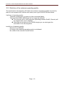
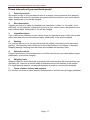
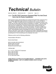
isel-CNC-Compact-Machine ICV 4030 CAN User Manual isel Germany AG, D-36124 Eichenzell, Bürgermeister-Ebert-Str. 40 (06659)981-0 (06659)981-776 All information, technical data, and dimensions contained in this booklet correspond to the technical state at the moment of publication. However, possible misprints or mistakes cannot be ruled out. We will appreciate all suggestions for improvement and error notes. We would like to point out that all used soft and hardware names of the respective companies generally are subject to protection by brand, trademark, and patent law. All rights reserved. It is prohibited to process, duplicate, or reproduce this booklet partially or on the whole in any form (print, copy, or other procedure) without written permission of isel Germany AG. This booklet has been translated from the original German version into English language. It does not lay claim to completeness nor flawlessness. In case of doubt the German original has validity. Manufacturer: isel Germany AG Bürgermeister-Ebert-Straße 40 D-36124 Eichenzell Tel.: (06659) 981-0 Fax: (06659) 981-776 Email: [email protected] http://www.isel.com Art.-No.: Status: 11/2011 ICV 4030 – CNC machine with CAN control This manual contains the operating instructions for the ICV 4030-Router (CAN machine control system) ans its following components : - housing incl. linear drive units with brush-type DC motors - control electronics : servo amplifier IMD10 with CAN-bus interface, isel system module ISM10 with safety circuit module and CAN-I/O-module 16/16, power supply 48VDC/500W as operating voltage for the servo amplifiers - integrated control PC ISR20 with built-in CAN interface PCI-CAN - ProNC, RemoteWin, and isyCAM2.5 software isel- machines and controllers are concurrent with CE norms and marked accordingly. Start-up of all other machine parts or components, for which CE safety regulations apply, is prohibited until all respective requests are met. isel Germany AG as the manufacturer cannot take over guarantee if you change the machine in any way. The EMC-test is valid only for the machine´s original configuration ex works. Basic knowledge in CNC-technology and PC application, such as Windows2000 or Windows XP are a prerequisite for your work with the ICV 4030. Please follow the instructions of this manual so that you can install the system properly, work safely, quickly, and efficiently, keep away danger from persons, and thus tap the full machine´s potential. For starting to work with this machine we recommend you to carry out the machining exercises of the ProNC and RemoteWin software . We wish you a lot of success and pleasure for your work with the ICV 4030. Contents 1 Application ..................................................................................................................... 1 2 Security Advice.............................................................................................................. 2 2.1 General ......................................................................................................... 2 2.2 Ageing of safety panes ................................................................................. 2 3 Setting Up and Connecting ........................................................................................... 3 4 Cleansing / Maintenance ............................................................................................... 4 5 Starting Up ..................................................................................................................... 6 5.1 Prearrangements .......................................................................................... 6 5.1.1 Operating the integrated control-PC 6 5.1.2 Installing the software 6 5.1.3 Coordinate system 6 5.1.4 Bearbeitungsmaschine 7 5.1.5 Machine tool 7 6 Important Operating Instructions................................................................................. 8 6.1 Operating devices......................................................................................... 8 6.1.1 Switches and connections on the backside 8 6.1.2 Buttons and switches on the frontside 8 6.2 First startup................................................................................................. 10 7 Technical Data ............................................................................................................. 11 7.1 Mechanics .................................................................................................. 11 7.1 Overview of electronic components ............................................................ 12 8 Malfunctions ................................................................................................................ 13 9 Accessories ................................................................................................................. 13 10 Appendix ...................................................................................................................... 14 10.1 Declaration of Conformity ........................................................................... 14 10.2 Definition of the minimum operating quality ................................................ 15 10.3 Service supply note .................................................................................... 16 ICV 4030 - CNC-Compact-Machine with CAN Controller 1 Application The ICV 4030 machine tool comes with three linear units, which are controlled by electronics and software. An additional unit (rotary or linear) is available. - This machine is designed for educational purpose and small-series production. - It is designed for the use in dry rooms, business premises, living and school areas as well as laboratories and small factories (at a max. ambient temperature of 40°C (104°F)). - It is suitable for milling, drilling, cutting, engraving, dosing, measuring, positioning and many other similar applications. - In accordance with above-mentioned applications all sorts of suitable machining or measuring tools can be loaded. - Rraw materials such as light metal, plastics, wood, glass, and circuit -board material are suitable for machining. For safety reasons graphite material is not permitted (explosion risk). Nor are materials permitted that emit harmful gases when beeing processed. - The machine is prepared to hold a dust removal system which preferably should be used to remove dry dusts such as from wood, circuit-board material, etc. - The machine´s control system holds integrated the entire control and power electronics for three (or 4) drive units. - Optional, three 24V outputs and three 24V inputs are available to connect further electrical or electronical components (ohmic consumer). - Using the software “isyCAD/CAM” you can optionally pass on previousely generated CNC-data directly into the machine through the control software “ProNC / RemoteWin” and thus have the work piece beeing machined. Page - 1 ICV 4030 - CNC-Compact-Machine with CAN Controller 2 Security Advice 2.1 - - - - - - - - - - General Do not operate the machine in a potentially explosive atmosphere. The machine is fully enclosed. The housing protects you from moving tools, reduces the noise level and holds back chips. The hood is locked during operation and cannot be opened. Please do not change or remove this mechanism. The safety circuit includes soft and hardware. Therefore the machine will only work with the appropriate and proper working control-core on the circuit-board (only type 2 and 3). In case of emergency, you will find an emergency stop switch on the front side of your machine. It will interrupt power supply for the power amplifier. However, communication between software and the machine will remain active for error diagnostics. Because of an increased risk when operating the machine in test-mode only briefed experts may make use of the key switch. Please keep the spare key shut away. All 230V-consumers are connected in a unipolar way you have to assume that they are not necessarily free from tension when switched off. Please provide sufficient ventilation to remove dusts and gases resulting from the processing of the material. If you want to use a laser for measuring application, only use appropriate class-2devices and follow the respective technical rules. Do not use running water for cooling but a spray-cooling system with a spray-fog causing the cooling effect (look accessories). Drop formation and their gathering below the mounting table must be avoided. Do not use spiritus as a coolant (danger of explosion!). Regularly clean the machine from chips and dust deposits. 2.2 Ageing of safety panes An examination conducted by the „Verein Deutscher Werkzeugmaschinenfabriken e.V.” (VDW) and the Employer's Liability Insurance Association has led to new discoveries about the ageing of polycarbonate beeing used for safety panes of machine tools. Altough polycarbonate has proved perfectly well for that purpose, these panes are losing their ability to protect against flying parts, particulary under the influence of cutting fluids. Polycarbonate panes that are protected from both sides against the effects of chips, cutting fluids, cleaning agents, vapours, etc. provide the best resistibility on the long term. We would like to point out that safety panes made from polycarbonate regularly have to be examined with respect to their protectability and, if necessary, be replaced. Beeing the operator of such machines it is within your duty of care. Such saftey panes, in the future, will be classified as wear parts. Furthermore you are commited to indicate the respective matter to a possible buyer of the machine. Despite these new discoveries, polycarbonate as a material for safety panes within the field of mechanical engineering still will be used for it´s extremely high protectability. We therefore can provide you any time with ready to be installed spare panes. If required, we can also offer you a retrofitkit as an additional protection on the operator´s side, in order to increase the required exchange intervals. Page - 2 ICV 4030 - CNC-Compact-Machine with CAN Controller 3 Setting Up and Connecting The machine will be delivered ready assembled on a pallet. The scope of delivery of the ICV 4030 includes : housing, including three linear drive units complete control electronics drilling and milling spindle with 3mm collet chuck chuck key, size 22 clamping set (hand lever, stop rail, 5mm-Allan key) triangular wrench to unlatch the hood switch line cord, connecting line from PC to machine quad socket with lighted master switch ProNC or RemoteWin software (optional) CAD/CAM-software isy-CAM (optional) the present user manual the required space for the machine amounts to its exterior dimensions and sufficient space for operating and setting the machine on the front side. Allow some 10cm on the back side for the plugs. The housing hood opens upwards, total hight requirement is some 1.2 meters. dimensions and space requirement Keep the triangular wrench off-machine, above all during transportation. The clamping set consists of a hand lever – clamping mechanism and two stop rails including fixing material for the T-slot plate. Always make sure that the workpieces are well fixed. Page - 3 ICV 4030 - CNC-Compact-Machine with CAN Controller 4 Cleansing / Maintenance Before turning off the machine push the master switch to open the hood. Afterwards it will not be possible. Before cleansing and/or maintenance of the machine, always turn off the master switch and pull the mains plug in order to avoid the turning on by mistake. - Regularly clean the machine from all chips by using a brush or a vacuum cleaner (do not apply compressed air). This will preserve the mechanical parts from early wear. - It is advisable to regularly remove the covering plate of the Y-axis underneath the T-slot plate in order to remove possibly penetrated chips or dusts at bigger volumes of chip production and when the chips are very fine. - The sealing lips come with a Teflon component. Particular maintenance is not required. - Clean the plastik washers with a non-abrasive liquid cleaning agent. The guiding rails as well as the drive shafts are provided with a long-time greasing ex works. Regrease them after 500 – 1000 working hours, according to the applied load. You may use common roller bearing grease for that purpose. All guiding rails and shafts are greased with the soda soap grease GP00/000F-20 according to DIN 51 502. In case you use oil, lubricate regularly every 100 – 200 working hours. In order to grease the drive shaft, first do a reference move then open the hood and last turn off the machine. To grease the Y-axis move the T-slot plate all the way to the front* and unscrew it from the Y-axis ( 6 screws). Remove the plastic plug underneath. Grease through the now visible lubricator nipple. The guiding rails are accessible through the sealing lips. To remove the cover plate of the Y-axis, release the fixing screws all around. S inicates in all drawings the access to the points to grease. Page - 4 ICV 4030 - CNC-Compact-Machine with CAN Controller As to lubricating the X-axis, move the slide to the left*, remove the plastic plug at the left side of the machine and grease through the now visible lubricator nipple. Again, the guiding rails are accessible through the sealing lips. With regard to the Z-axis, first remove the machine tool from its fixture then remove the three plugs and push the slide all the way down. * Through the two lateral openings, some lubricant can be applied onto the guiding rails . Behind the front opening you will find the lubricator nipple for the drive. * While the machine is turned off, the slide can be moved manually. Page - 5 ICV 4030 - CNC-Compact-Machine with CAN Controller 5 Starting Up 5.1 Prearrangements 5.1.1 Operating the integrated control-PC For operating the control-PC you need: a screen with VGA attachment PS2/USB mouse PS2/USB keyboard 5.1.2 Installing the software For programming and running the control system of the machine the ProNC or RemoteWin software is needed. In case the included software has not yet been installed and adjusted in the factory, please refer to the notes regarding software installation on the installation-CD. 5.1.3 Coordinate system The machine´s coordinate system is defined as shown in the picture below. You can freely select and move the starting point PO on the workpiece through the software . However, the machine´s reference point (machine zero point) from the factory is set to the front (Y) left (X) and top (Z) of the machine. stickers on the machine identify the axes. Page - 6 ICV 4030 - CNC-Compact-Machine with CAN Controller 5.1.4 Bearbeitungsmaschine 5.1.5 Machine tool The collet chuck (4) of the standard machine tool can hold different tools with a shank diameter up to max. 6,35mm (standard 3 mm, other Ø refer to accessories). Use two spanners size 22 for changing the collet chuck . Power supply for the machine tool will be enabled by the software. The speed of revolutions can be set manually by the thumb wheel (1). To dismount the machine tool, turn off the main switch of the ICV 4030, disconnect the line cord from the distribution box, release the locking screw (2) and take the machine tool out of its fixture. To dismount the machine tool together with its fixture, turn off the main switch, disconnect the line cord from the distribution box, release the outer screws (3) (just release, not unscrew) and take out downwards the machine with its fixture and the T-nuts. Many other tools, measuring instruments (laser) or other devices can be mounted onto the T-slot plate of the Z-axis by using the appropriate fixtures. Use the distribution box of the Z-axis for electrical connection. When you mount the machine tool or other tools, you have to adjust the fixture again parallel to the XY-plane. Page - 7 ICV 4030 - CNC-Compact-Machine with CAN Controller 6 Important Operating Instructions 6.1 Operating devices 6.1.1 Switches and connections on the backside number designation 1 VGA connector 2 PS/2 Mouse 3 PS/2 keyboard 4 Power supply connector description Connector 15-pin VGA monitor Connector for PS/2 Mouse Connector for PS/2 keyboard 230V AC power supply connector with main switch and fuses 2 x 10A time-lag HBD 6.1.2 Buttons and switches on the frontside Page - 8 ICV 4030 - CNC-Compact-Machine with CAN Controller Operating devices to control the machine number designation description 1 Emergency Stop button 2 Power ON button 3 Fault indicator 4 Start button Starts the processing of the current NC-program or continues an interrupted processing. 5 Stop button Interrupts the processing of the current NC-program. The repeated pressing of the Stop button will abort the processing (not for all control configurations valid). Turns off the power supply for the motor power amplifier and the working spindle. Turns on the power supply for the power amplifiers. The fault indicator indicates an error within the safety circuit. This button is used to open the hood (if existing). The hood may only be opened when the Cover button is highlighted (axes must be in HOME position or operating mode switch is set to “Test”). 6 Cover button 7 ACK (Acknowledge) button 8 operating mode switch Note: To open the hood with the COVER button press the hood shortly down therewith the tongue of the Schmersal-switch is released. After that push the hood upstairs. Press this button in order to move the axes when the machine is in setup-mode and the hood is open. Use this key-operated switch to switch between automatic and setup-mode. In automatic mode the hood (resp. door) can only be opened when all axes are in their HOME position. In setup-mode the hood can be opened and pushing the ACK button, axes can be moved. Operating devices for the control-PC number designation description 9 Power button Turns on the integrated control-PC. 10 Power-LED Operation indicator of the control-PC. 11 HDD-LED Indicator for access to the hard disk. 12 USB slots USB 2.0 slots for USB devices (USB Stick, WIBU etc.) Page - 9 ICV 4030 - CNC-Compact-Machine with CAN Controller 6.2 First startup At the first startup, please conduct following steps: - To open the hood for the first time plug in the line cord and turn on the master switch. The COVER button should be highlighted. Only with that button highlighted will it be possible to open the hood. - For all following functions the emergency stop has to be unlocked. - Close the hood and turn on the power amplifiers by pressing the POWER button. The button has to be highlighted. - You can call the software any time. An error message will appear if the machine is not ready for operation (power amplifiers not turned on). - The hood is locked during the machining process. It can only be opened when the machine stands still, the machine tool is turned off and the software allows the hood to be opend (COVER button is highlighted). - To open the hood you have to press the COVER button. After closing the hood it will be locked automatically. To start the machine, press again the START button. Please refer to the software manual for all further information regarding the working with the software. Key-operated switch If you want to check the program, the hood can be opened during operation when you switch the key-operated switch to TEST (test mode). For this the machine tool must be turned off, the program, however, will continue. Make sure the tool is disengaged from the workpiece! When the hood is open, protection from moving parts of the machine is not guaranteed any more ! Therefore the key should only be used by authorized experts ! Machine tool The machine tool is directly wired and controlled by the software. As well are the three other, optional switching outputs, which can be used to control additional devices (refer to technical data). The machine tool can be turned on only when the POWER button is highlighted, the hood is closed and locked, the rotary switch is ON and the software is controlling the machine. Page - 10 ICV 4030 - CNC-Compact-Machine with CAN Controller 7 Technical Data 7.1 Mechanics ICV 4030 CAN Dimensions length x width x hight [mm] 780 x 835 x 810 Traversing range X-Achse [mm] 395 Y-Achse [mm] 300 Z-Achse [mm] 100 Traverse speed (X/Y/Z) [mm/s] >150/150/80 Admission hight [mm] 150 Clamping surface (length x width) [mm] 600 x 375 T-slot grid [mm] 25 Weight approx. [Kg] 150 Sound pressure level SPL [db(A)] <75 Power supply 230V, 50Hz, external fuse 16A Drive motor 120 Watt each Milling spindle motor depending on the type Fuse power input 2 x 10A time-lag HBD Earthing corresponds to safety class 1 Page - 11 ICV 4030 - CNC-Compact-Machine with CAN Controller 7.1 Overview of electronic components system module iSM 10 control PC iSR20 breaking chopper frequency converter for milling spindle motor power amplifier iMD 10 power supply unit 48VDC 1000W PFC Page - 12 ICV 4030 - CNC-Compact-Machine with CAN Controller 8 Malfunctions malfunction machine cannot be turned on cause no power supply master switch not turned on broken fuse POWER button out of function hood not closed emergency stop not unlocked broken fuse machine not turned on software does not work properly power amplifier not turned on driver not installed bad connection machine tool does not work properly not enabled by the software rotary switch not on solution check mains supply, mains plug, multiple socket turn on unplug mains plug and replace fuse (see below) close hood unlock emergency stop unplug mains plug and replace fuse (see below) turn master switch on turn on (POWER button) install driver check cable connections do a system reset and a reference move turn on machine tool change the pitch value in traverse distances of spindle pitch does not correspond the software (refer to the axes not correct to the software settings control manual) 9 Accessories The ICV 4030 CAN suitable accessories can be ordered: accessorie dust collector lighting for working area graving pad length calliper spray-cooling system rotary unit drilling and milling machine 500 W drilling and milling machine 1050 W clamping fixture stop rail milling cutter item number 280110 9001 280110 9004 280120 9003 280120 9010 280220 9012 e.g. 263013 0001 420003 2050 420003 1050 e.g. 690001 e.g. 290021 0175 e.g. 804110 5000 Make sure all accessories are correctly installed and follow applicable norms and safety regulations. You will find installation and operating instructions for the accessories in the appendix. For further information or order placements please turn to our technical consulting service. Page - 13 ICV 4030 - CNC-Compact-Machine with CAN Controller 10 Appendix 10.1 Declaration of Conformity Declaration of Conformity corresponding Machinery Directive 2006/42/EU, Annex II A The manufacturer isel Germany AG Bürgermeister-Ebert-Straße 40 D-36124 Eichenzell declares hereby, that the following products Product designation: isel-compact-CNC-machine with safety hood Types: ICV 4030 CAN Item-No.: 280230 4405 conforms to the safety and health requirements of the Machinery Directive 2006/42/EU, Annex I – including those at the time of declaration current alterations.. The following harmonized standards have been applied: EN ISO 12100-1:2003 Safety of machinery – fundamental terms, general principles of design – Part 1: Basic terminology, methodology EN ISO 12100-2:2003 Safety of machinery – fundamental terms, general principles of design – Part 2: Technical principles EN ISO 13857:2008 Safety of machinery – Safety distances to avoid reaching of dangerous regions with upper and lower extremities EN 349:1993 Safety of machinery – Minimum distances to avoid bruising of parts of the body EN 953:1997 Safety of machinery – Guards – general requirements for the design and construction of fixed and moveable guards EN 954-1:1996 Safety of machinery – Safety related parts of control systems, Part 1: General principles for design EN ISO 13850:2008 Safety of machinery – Emergency-Halt – Design guidelines EN 14121-1:2007 Safety of machinery – Risk assessment – Part 1: Guidelines EN 60204-1:2006 Safety of machinery – Electrical equipment of machines, Part 1: General requirements Also the following EU Directives have been applied EMC Directive 2004/108/EG Low Voltage Directive 2006/95/EG The technical documentation for this machine was created corresponding Annex VII Part A. The manufacturer obligates to provide the technical documentation in electronic mode on demand of authorized governmental agency. Representative for composition of technical documentation is: Mr. Helmut Danz Dermbach, 18.01.2010 Werner Kister, Managing board Page - 14 ICV 4030 - CNC-Compact-Machine with CAN Controller 10.2 Definition of the minimum operating quality The manufacturer isel Germany AG defines the minimum operationg quality for immunity tests for isel-compact-CNC-machine with safety hood, type ICV4030 CAN as follows: Valid loss of operating quality: - Temporary malfunction (no picture) oft he connected display - The connected WIBU-USB-dongle will no longer be detected The execution oft he user programm (operating software ProNC, Remote) will be stopped with a error message. After plug out and plug in oft he WIBU-dongle you can start again the execution of the user programm. Invalid loss of operating quality: - Data loss is not allowed. - A change of the selected operating mode is not allowed. - No motion oft he axis after function failure. Page - 15 ICV 4030 - CNC-Compact-Machine with CAN Controller 10.3 Service supply note Sender company customer-ID number refrence person / department telephone ______________________________________________ ______________________________________________ ______________________________________________ ______________________________________________ _______________________fax____________________ Address ______________________________________________ return delivery to ______________________________________________ quantity item-number designation invoice-no. delivery note-no. (please add copy) serial-number Cause for Complaint a) commercial complaint O wrong delivery O wrong quantity O_________________________________________________ b) technical complaint error description: when does the error occur ? O constantly O sporadically O temperature-dependent O after ___ minutes of running time has the item already been in use ? O not yet used O defect at starting up __ months of use date _____________ signature __________________________________ Page - 16 ICV 4030 - CNC-Compact-Machine with CAN Controller Please take notice if you send back goods ! 1. Proof of purchase We require a copy of your purchase invoice or a delivery note to examine your warranty claim. Unless such a proof is enclosed, the goods will be sent back at your costs without repair. Additionally, a fee will be charged. 2. Error description If goods are sent to us without a detailed error description (“defect” or “for repair” is not sufficient), we will either do a diagnosis of errors at your costs or return the goods at your costs without repair. Additionally, a fee will be charged. 3. Unjustified claims If your claim is not justified (no error can be found, an operator´s error is likely) the goods will be sent back at your costs without repair. Additionally, a fee will be charged. 4. Packing For a return delivery to us, we only will accept the original isel-packing or an equivalent packing. Your warranty claim will be put at risk if the packing is not original or improper. Shipping damage resulting from that issue will invalidate the warranty claim. 5. External products Products which were not purchased from us will be sent back at your costs without repair. Additionally, a fee will be charged. 6. Shipping costs Shipping costs for return deliveries of products with valid warranty will be covered by isel Germany AG. Costs for all others kinds of shipments are at the expense of the sender. For organizational reasons, not prepaid shipment of goods to us cannot be accepted. 7. Terms of sales, delivery and payment For the rest, the terms of sales, delivery and payment of isel Germany AG apply unaltered. Page - 17